US8060290B2 - Configurable automotive controller - Google Patents
Configurable automotive controllerDownload PDFInfo
- Publication number
- US8060290B2 US8060290B2US12/174,910US17491008AUS8060290B2US 8060290 B2US8060290 B2US 8060290B2US 17491008 AUS17491008 AUS 17491008AUS 8060290 B2US8060290 B2US 8060290B2
- Authority
- US
- United States
- Prior art keywords
- calibration
- control unit
- dataset
- controller
- engine control
- Prior art date
- Legal status (The legal status is an assumption and is not a legal conclusion. Google has not performed a legal analysis and makes no representation as to the accuracy of the status listed.)
- Active, expires
Links
Images


Classifications
- G—PHYSICS
- G05—CONTROLLING; REGULATING
- G05B—CONTROL OR REGULATING SYSTEMS IN GENERAL; FUNCTIONAL ELEMENTS OF SUCH SYSTEMS; MONITORING OR TESTING ARRANGEMENTS FOR SUCH SYSTEMS OR ELEMENTS
- G05B13/00—Adaptive control systems, i.e. systems automatically adjusting themselves to have a performance which is optimum according to some preassigned criterion
- G05B13/02—Adaptive control systems, i.e. systems automatically adjusting themselves to have a performance which is optimum according to some preassigned criterion electric
- G05B13/04—Adaptive control systems, i.e. systems automatically adjusting themselves to have a performance which is optimum according to some preassigned criterion electric involving the use of models or simulators
- G05B13/048—Adaptive control systems, i.e. systems automatically adjusting themselves to have a performance which is optimum according to some preassigned criterion electric involving the use of models or simulators using a predictor
- G—PHYSICS
- G05—CONTROLLING; REGULATING
- G05B—CONTROL OR REGULATING SYSTEMS IN GENERAL; FUNCTIONAL ELEMENTS OF SUCH SYSTEMS; MONITORING OR TESTING ARRANGEMENTS FOR SUCH SYSTEMS OR ELEMENTS
- G05B15/00—Systems controlled by a computer
- G05B15/02—Systems controlled by a computer electric
Definitions
- the inventionpertains to automotive controllers and particularly to configuring such controllers.
- the inventionis a system having a general multi-parameter model predictive controller template in an embedded engine control unit such that long software coding changes requiring large amounts of time are bypassed.
- FIG. 1illustrates an example related art graph of constraints for the optimization vector ⁇ right arrow over (u) ⁇ (x k ) using multi-parametric quadratic programming algorithm
- FIG. 2illustrates an example related art graph of critical regions for a parameter vector x k utilizing a multi-parametric quadratic programming algorithm
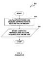
- FIG. 3illustrates a high-level flowchart depicting an off-line method for the design and implementation of optimal multivariable MPC controllers using an MP-QP algorithm
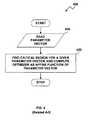
- FIG. 4illustrates a high-level flowchart illustrating an on-line method for the design and implementation of optimal multivariable MPC controllers using an MP-QP algorithm
- FIG. 5illustrates a schematic diagram depicting a general control system with an optimal MPC controller utilizing an explicit QP solver
- FIG. 6illustrates a high-level flowchart illustrative of an off-line method for design and implementation of optimal multivariable MPC controllers using a primal-dual feasibility algorithm
- FIG. 7illustrates a high-level flowchart illustrative of an on-line method for design and implementation of optimal multivariable MPC controllers using the primal-dual feasibility algorithm
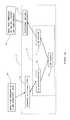
- FIG. 8illustrates a detailed flowchart illustrative of an off-line method for design and implementation of optimal multivariable MPC controllers using the primal-dual feasibility algorithm
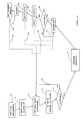
- FIG. 9illustrates a detailed flowchart illustrative of an on-line method for design and implementation of optimal multivariable MPC controllers using the primal-dual feasibility algorithm
- FIG. 10illustrates a high-level flowchart illustrative of an off-line method for design and implementation of optimal multivariable MPC controllers using a graph algorithm
- FIG. 11illustrates a high-level flowchart illustrative of an on-line method for design and implementation of optimal multivariable MPC controllers using the graph algorithm
- FIG. 12 ais a diagram of an automotive control development approach
- FIG. 12 bis a diagram showing an integration of a real-time template
- FIG. 12 cis a diagram showing configuring and calibration of a controller with skipping controller software changes
- FIG. 12 dis a diagram showing a compiling of a controller algorithm and dataset together
- FIG. 13is a diagram of a control functional block in an automotive engine control unit
- FIG. 14is a diagram similar to the diagram of FIG. 13 except a model predictive control template functional block of the present invention is substituted in place of the control functional block of FIG. 13 ;
- FIG. 15is a diagram of an internal structure of the model predictive control controller in FIG. 14 ;
- FIG. 16is a diagram of engine control unit software architecture
- FIG. 17is a diagram of a development process for a control functional block
- FIG. 18 ais a diagram of a developmental approach of the present invention for a control functional block.
- FIG. 18 bis a diagram of a developmental approach of the present invention that compiles controller code and a calibration dataset together.
- An approach of the present inventionmay include the use of a model predictive control (MPC) controller on an OEM's control hardware and software platform.
- the approach or systemmay be enabled in that the controller is configurable via a calibration dataset without a requirement to enter a laborious software development process shown FIG. 12 a .
- the present approachmay permit an optimal multivariable controller to be configured strictly through populating a template with data.
- the term “present” used in this descriptionmay refer to the invention.
- MPC controlmay be formulated as a general optimization problem.
- the control objectivesmay be expressed by a criterion function or a cost function and by defining system constraints.
- the control actionmight be achieved by solving the optimization problem numerically at each sampling period in cases where there exist sufficient computing resources.
- a nonlinear modelmay describe the behavior of a system relatively well, but it is more difficult to formulate and to solve MPC based on nonlinear MPC models than the linear models.
- a linear modelmay describe the dynamic behavior of the system well in a certain neighborhood of an operating point. The parameters of the linear model might be identified by utilizing data obtained from an identification experiment.
- This modelmay be utilized to predict future system trajectories based on information related to the current system state, i.e., x k .
- the predictionmay be provided, for example, by equations (1.2) and (1.3) below.
- x ->⁇ P x x ⁇ x k + P u x ⁇ u -> k
- y ->⁇ P x y ⁇ x k + P u y ⁇ u -> k
- x ->⁇ [ x k + 1 x k + 2 ⁇ x k + N ]
- y ->⁇ [ y k y k + 1 ⁇ y k + N - 1 ]
- u ->⁇ [ u k u k + 1 ⁇ u k + N - 1 ] ( 1.4 )
- P x x , P u x , P x y , P u yare corresponding matrices.
- the objectives for MPC controlmay generally be expressed as a cost function.
- the cost functionmay be quadratic with linear constraints, which leads to Quadratic Programming (QP) problems. Therefore, the final form of the cost function may be influenced by many factors.
- the basic formmay be written as indicated, for example, in equation (1.5) below:
- r kis the reference signal
- ⁇ u ku k ⁇ u k ⁇ 1.
- equation (1.4)Using equation (1.4) and by introducing linear constraints, the optimization problem of MPC control may usually be transformed to the matrix form of equation (1.7) as follows:
- u -> *arg ⁇ min u -> ⁇ ⁇ 1 2 ⁇ u -> T ⁇ H ⁇ u -> + x k T ⁇ F ⁇ u -> + ⁇ ⁇ ⁇ s . t . G ⁇ u -> ⁇ W + Vx k ( 1.7 )
- H and Frepresent corresponding matrices
- G, W and Vrepresent matrices defining constraints.
- the optimization problemmight be formulated as a Quadratic Program (QP), if the model utilized by the MPC controller is linear.
- QPQuadratic Program
- the QP problem as illustrated by equation (1.7) abovemay be solved numerically or explicitly in each sampling period for systems with relatively large sampling periods.
- the numerical solutionis not necessarily possible for applications with relatively short sampling periods or when control is to be implemented in restricted computing environments such as the embedded systems used in automotive applications.
- An explicit solution to QPmay be as a multi-parametric quadratic programming (MP-QP) approach and may enable relatively fast-sampling periods.
- the explicit solution to QPmay be computed in two stages, which are typically divided into an off-line part and an on-line (i.e., “online”) part.
- the off-line partmay be utilized for pre-computations in order to save on-line time in each sampling period of MPC control.
- the new optimization problemmay generally be given by the following equation (1.9):
- the set of inactive constraintscan be defined by equation (1.13): i NA ( x k ) ⁇ i ⁇ I;G i z *( x k ) ⁇ W i ⁇ S i x k ⁇ 0 ⁇ (1.13)
- equation (1.17)needs to satisfy constraints in equation (1.9) and Lagrange multipliers of equation (1.16) need to be nonnegative, as required by the fourth condition in equation (1.14). Both conditions may be rewritten to the form of (1.18) as follows:
- example related art graphs 100 and 200are illustrated, which represent the constraints for optimization vector ⁇ right arrow over (u) ⁇ (x k ) and critical regions for a parameter vector x k using a multi-parametric quadratic programming algorithm.
- the stored matrices from equation (1.8) to (1.18)may be utilized in the on-line part of the multi-parametric quadratic programming algorithm to determine the optimal solution ⁇ right arrow over (u) ⁇ *(x k ) for the given parameter vector x k .
- system constraints for the optimization vector ⁇ right arrow over (u) ⁇ (x k )may be plotted using the stored matrices from equations (1.8) to (1.18).
- the critical regions CR i A associated with a given set of active constraints indexed by i Amay be defined by the inequality (1.18).
- the optimal solution associated with CR i Amay be given by (1.17).
- the parameter spacemay be partitioned so that all partitions for all feasible combinations of constraints i A (1.18) and associated affine functions for z*(x k ) (or more precisely u k *(x k ) by using transformation (1.8)) may be computed for an optimal on-line control action.
- the pre-computed critical regions CR i Aj for j1, 2, . . . n, where n is the total number of critical regions, and the affine functions for u k *(x k ) are stored, where the stored matrices may be defined as follows:
- M 1 j⁇ [ GH - 1 ⁇ G i Aj T ⁇ ( G i Aj ⁇ H - 1 ⁇ G i Aj T ) - 1 ⁇ S i Aj - S ( G i Aj ⁇ H - 1 ⁇ G i Aj T ) - 1 ⁇ S i Aj ]
- m 1 j⁇ [ - GH - 1 ⁇ G i Aj T ⁇ ( G i Aj ⁇ H - 1 ⁇ G i Aj T ) - 1 ⁇ W i Aj + W - ( G 1 Aj ⁇ H - 1 ⁇ G i Aj T ) - 1 ⁇ W i Aj ]
- M 2 j⁇ ( - H - 1 ⁇ F + H - 1 ⁇ G i Aj T ⁇ ( G i Aj ⁇ H - 1 ⁇ G i Aj T ) - 1 ⁇ S i Aj )
- FIG. 4illustrates a related art flowchart depicting an on-line method 400 for the design and implementation of optimal multivariable MPC controllers utilizing an MP-QP algorithm.
- actual value of parameter vector x kmay be read in the on-line part.
- the active critical region CR i Amay be determined for the actual value of parameter vector x k
- the optimal control law u k *(x k )may be computed by utilizing the associated affine function and the active critical region.
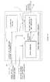
- FIG. 5illustrates a schematic block diagram of a general control system 500 with optimal MPC controller 510 utilizing an explicit QP solver 520 .
- the control system 500may be adapted with MPC controller 510 for controlling, for example, an automotive system 530 by utilizing an explicit QP solver 520 .
- MPC controller 510may include a model of the dynamic operation process of the automotive system 530 .
- MPC controller 510may further provide predictive control signals to the automotive system 530 , which might be subjected to constraints in control variables and measured output variables.
- the predictive control signalsmay be generated by determining the state of physical plant 505 utilizing actuators 504 , sensors 506 and state observer 501 in MPC controller 510 .
- the actuators 504 and the sensors 506may be directly interconnected with a physical plant 505 , such as an engine.
- the explicit QP solver 520may be implemented within MPC controller 510 , and divided into an off-line portion 502 and an on-line portion 503 .
- the explicit QP solver 520may solve the optimization QP problems by using one of the optimization algorithms such as multi-parametric quadratic programming, primal-dual feasibility algorithm and graph algorithm.
- the state observer 501may generally receive present and/or past values for a number of inputs y(k) from the sensors 506 and number of control outputs u(k) of the actuators 504 .
- the state observer 501may produce a current set of state variables x(k) to the on-line portion 503 of the explicit QP solver 520 .
- the on-line portion 503 of the QP solver 520may compute the control outputs u*(k) based on the state variables x(k) and the stored matrices in the off-line portion 502 of the QP solver 520 . Therefore, MPC controller 510 may control the effect of changes in the state of the actuators 504 on each input parameter using the computed control outputs u*(k) in order to produce a desired target value in input and output parameters of the engine 505 .
- the control outputs u*(k)may be updated constantly, intermittently or periodically for achieving optimal multivariable control of the engine 505 .
- MPC controller 510 with the explicit QP solver 520may be implemented as an electronic controller unit (ECU) in automotive control applications, in particular motor vehicle.
- ECUelectronic controller unit
- FIG. 6a high-level flowchart of an off-line portion 600 for the design and implementation of optimal multivariable MPC controllers 510 using a primal-dual feasibility algorithm is illustrated.
- the MP-QP algorithmmay be modified for producing the primal-dual feasibility algorithm, which enables one to save memory while keeping CPU utilization in the on-line part. Many of the equations may be common for both approaches.
- the off-line portion 600may compute matrices and vectors for use in the on-line part.
- matrices and vectors for all feasible combinations of active constraints in the automotive system 530may be computed in order to calculate the Lagrange multipliers and the optimizer in the on-line part.
- the computed matrices and vectorsmay be stored in the off-line portion 502 of the QP solver 520 .
- the computed matricesmay define the constraints of QP optimization problem.
- Multivariable MPC controllers 510 with the primal-dual feasibility approachcan be implemented as a computer program on a specialized real-time control platform.
- the optimization schememay be applied in each sampling period of the MPC control algorithm.
- the parameter vector estimated by the state observer 501may be read initially.
- the parameter vectormay be checked through all feasible combinations of the active constraints in the automotive system 530 .
- the Lagrange multipliersmay be calculated in order to determine the dual feasibility of the parameter vector using matrices and vectors stored in the off-line portion 502 of the QP solver 520 . If the parameter vector is not dual feasible, then the next feasible combination of the active constraints may be checked for dual feasibility.
- an optimizer candidatecan be calculated in order to determine the primal feasibility (PF) in the parameter vector, if the parameter vector is found to be dual-feasible. If the parameter vector is not one that leads to a primal feasible optimizer candidate, then the next feasible combination of the active constraints may be examined in order to determine the optimizer. The QP optimization problem may be solved by utilizing the optimizer. The dual-primal feasibility-checking step may then be terminated, when either the parameter vector leads to dual-primal feasibility (the solution has been found) or all feasible combinations of the active constraints have been checked without success (the solution has not been found).
- Such an “online” implementation of MPC controller 510 utilizing the primal-dual feasibility algorithmmay reduce a search of the solution space and implementation usage of the appropriate parameter vector.
- “online”may generally refer to the use of or access to a computer and/or computer network such as the “Internet” and/or an “Ethernet”.
- An example of an “online” system which may be accessed and processedis system 2000 depicted and described in greater detail herein with respect to FIG. 20 .
- the appropriate matricesmay be calculated based on the corresponding constraints and matrices defining the QP problem.
- the vector of Lagrange multipliers ⁇ * i A (x k ) in the on-line parti.e., matrices ⁇ (G i A H ⁇ 1 G i A T ) ⁇ 1 S i A and ⁇ (G i A H ⁇ 1 G i A T ) ⁇ 1 W i A .
- z*(x k ) and u k *(x k )may be computed using the matrices ⁇ H ⁇ 1 G i A T and ⁇ H ⁇ 1 F T .
- the matrices M 1 j , M 2 j , M 3 j and the sets of indices i NAjmay be stored.
- M 4( ⁇ H ⁇ 1 F T ) (1 . . . n u )
- FIG. 9a high-level flowchart of an on-line method 900 for the design and implementation of optimal multivariable MPC controllers 510 using the primal-dual feasibility algorithm is illustrated. In the on-line part, an optimization scheme may be processed for each sampling period of the MPC control algorithm. As illustrated at block 901 , the parameter vector x k may be measured or estimated, for example by the state observer 501 .
- the matrices M 4 , M 5 , M 6 , M 7 , M 1 j , M 2 j , M 3 j and the sets of indices i NAj stored in the off-line portion 502 of the QP solver 520may be retrieved.
- the operationsmay continue to the process depicted at block 915 .
- H⁇ [ 2 0 0 1 ]
- F⁇ [ 1 0 0 1 ]
- ⁇⁇ 0
- G⁇ [ - 1 1 1 - 1 0 1 0 - 1 ]
- W⁇ [ 0 5 5 - 1 ]
- V⁇ [ 0 0 0 0 0 0 0 0 ] ( 1.25 ) and the parameter vector x k is constrained by
- the following matrices(see (1.24)) may be stored according to the off-line part of the control algorithm,
- M 1 1[ 0.3333 - 0.6667 ]
- M 2 10
- M 3 1[ 0.5 - 1 ] ( 1.27 )
- M 1 2[ 0 1 ]
- M 2 21
- M 3 2[ 0 1 ] ( 1.28 )
- M 1 3[ 1 0 1 1 ]
- M 2 3[ 2 3 ]
- M 3 3[ 0.5 0 - 1 1 ] ( 1.29 )
- M 4[ - 0.5 0 0 - 1 ] ( 1.30 )
- M 5[ - 1 1 1 - 1 0 1 0 - 1 ]
- M 6[ 0 5 5 - 1 ]
- M 7[ - 0.5 1 0.5 - 1 0 1 0 - 1 ] ( 1.31 )
- the stored matrices from (1.27) to (1.31)may be utilized in the on-line part of the primal-dual feasibility algorithm to find the optimal solution for the given parameter vector x
- the graph approach methodologymay be another approach to solve the optimization problem of the form (1.9).
- a directed graph structuremay be constructed and stored in the off-line part.
- the graphmay be utilized in the on-line part of the algorithm to find all primal-feasible candidates for optimizer in an efficient way.
- the graphmay be constructed to minimize the number of feasible candidates for optimizer.
- the optimizermay be determined within the set of all feasible candidates utilizing the cost function defining the optimization problem.
- the optimizermay be the candidate that leads to the lowest value of the cost function.
- the associated matrices M 2 j and vectors m 2 jmay be computed to calculate the optimizer, and also the directed graph structure may be prepared.
- the computed vectors and matrices H, F, G, W and V and the directed graph structuremay be stored, where the matrices G, W and V generally define the constraints of the original optimization problem.
- FIG. 11a flowchart of an on-line method 1100 for the design and implementation of optimal multivariable MPC controllers 510 using the graph algorithm is illustrated.
- the optimization schememay be performed in each sampling period of MPC control algorithm.
- the parameter vectormay be provided by the state observer 501 .
- all feasible candidates for optimizermay be found by performing breath-first search using the directed graph, the matrices and the vectors prepared in the off-line part.
- the candidates for optimizermay be calculated for each node in the breath-first search using equation (1.32), i.e., u k j (x k ). Then, the feasibility of the candidate may be checked by utilizing Gu k j (x k ) ⁇ W+Vx k . If the candidate is feasible, the node may be marked as “feasible” and all successors of the node may be recursively marked as “not-interesting”. Similarly, if the candidate is not feasible, the node may be marked as “not-interesting”.
- the optimal control action u* k (x k )may be equal to the candidate with smallest value of cost function J j (x k ).
- the optimizer candidate with the smallest criterion valuemay be utilized as the optimal solution for the given parameter vector x k .
- Previous automotive control approachesmay follow a V-model flow diagram in FIG. 12 a which includes a laborious process in a set 17 of steps.
- An implementation of a subcontroller with other approachesmay be in terms of lookup tables and fixed control elements, such as PIDs. Examples of such approaches are shown in FIGS. 12 a , 13 and 17 . Making changes in these approaches may require changes to a hard-coded algorithm and thus a return to functional block development.
- the present approachmay involve a one-time integration of a software template via a (perhaps potentially rather long) software process. Subsequent structure changes may then be straightforward and relatively quick via a calibration dataset.
- the present approachmay include an implementation of a model predictive control (MPC) controller which can be configurable through the calibration dataset.
- MPCmodel predictive control
- Various other kinds of MPCsmay be implemented.
- the MPCmay be a control technique which enables a user to specify measurements, setpoints, constraints, actuators and so forth, in a generic way. It may appear unusual to be able to use MPC in a computationally tight environment such as an embedded automotive engine control unit (ECU).
- ECUembedded automotive engine control unit
- Onemay use a multiparameter optimization technique in order to perform large computations offline and code only a small amount of computations in the online code.
- the present approachmay implement a general MPC template in the embedded ECU such that the long periods needed for software coding changes are significantly reduced or avoided for implementations in the system.
- Various kinds of MPCsmay be implemented in ECUs.
- the MPCmay be described in a paper entitled, “Constrained Model Predictive Control: Stability and Optimality”, by Mayne, D. Q., et al., in Automatica 36 (2000), 789-814.
- Multiparameter techniques for implementing MPC, particularly in limited computing environments,may be described in a paper entitled, “The Explicit Linear Quadratic Regulator for Constrained Systems”, by Bemporad, A., et al., in Automatica 38 (2002), 3-20.
- Patentsmay include: U.S. Pat. No. 7,155,334, issued Dec. 26, 2006; U.S. Pat. No. 7,165,399, issued Jan. 23, 2007; U.S. Pat. No. 7,275,374, issued Oct. 2, 2007; and U.S. Pat. No. 7,328,577, issued Feb. 12, 2008; all of which are hereby incorporated by reference.
- Patent applicationsmay include: U.S. patent application Ser. No. 11/024,531, filed Dec. 29, 2004; U.S. patent application Ser. No. 11/025,221, filed Dec. 29, 2004; U.S. patent application Ser. No. 11/025,563, filed Dec. 29, 2004; U.S. patent application Ser.
- the present systemmay include a flexible and user-friendly configurable controller based on (MPC) model based predictive control technology for use in an automotive control system that is implemented in an ECU (engine control unit).
- the MPC controllermay be based on an optimization challenge involving an explicit solution of the optimization problem which supports applicability to control systems with relatively fast-sampling and with low computation power and memory.
- the systemmay offer a strong tool that allows decreasing significantly the development and calibration time of the control system. It may include an implementation of a general MPC algorithm as a template for the embedded ECU that may be configured by a calibration dataset. An advantage of such an approach is that it may allow many different controller configurations which can be achieved through simply modifying the calibration dataset. Changes of the core MPC algorithm implemented inside the template may be mitigated or avoided altogether.
- the present systemmay be responsive to a need to decrease the time required for development and calibration of a control system for an automotive application.
- Thismay be achieved by designing and implementing a general template for MPC controller which can be parameterized by a calibration set.
- the calibration setmay contain information about parameters for configuring the structure of the controller but also parameters for tuning the control performances.
- Parameters influencing the structure of the controllermay include, for example, numbers of measured variables, set-points, constraints, actuators, and so on.
- Parameters influencing performancesmay include, for example, models of the controlled system, prediction horizon lengths, weighting matrices defining the control objectives and preferences of a resulting feedback control, covariance matrices for a state estimator, and so forth. Then if one would like to change the structure or tuning of the controller, it may be enough to modify the calibration dataset without modifying the MPC controller template.
- the templatemay be implemented in the ECU function block using, for instance, C programming language.
- the calibration datasetmay be generated off-line and stored in appropriate memory.
- the storagemay be, for example, a header file.
- an appropriate compilerto generate a target code for a target device, e.g., an ECU, where the target code is an instance of a configured MPC controller.
- the target code (MPC)may then be downloaded into the target device (ECU).
- a configuration of the controlleri.e., a structure of the controller or performances
- it may be sufficient to change the calibration datasetre-compile the controller template with the updated calibration dataset to generate a new target code (MPC) and download the new target code into the target device (ECU).
- MPCnew target code
- the present systemmay be further improved and the total calibration time may be further decreased when changes are only the part of the calibration dataset which influences performance of the control-loop.
- the structure of the controllermay remain fixed.
- the present systemmay be extended so that the part of the calibration dataset containing information about MPC controller performances may be replaced on-line, e.g., via a run-time regime.
- the systemmay further be extended so that one may be able to change the both parts of the calibration datasets, i.e., the part that defines the performances and the part that defines the structure of the controller in terms of a number of measured variables, set-points, constraints, actuators, and so forth.
- the present systemmay be implemented in SimulinkTM and MatlabTM which is regarded as a software tool for simulation and model-based design.
- the present algorithmmay be implemented as user function or a set of user functions in a SimulinkTM tool.
- a simulation scheme containing these functionsmay be a source for a target code generator.
- FIG. 12 ais a flow diagram of an automotive control development process.
- Step 11may indicate the specification of functional requirements of an automotive control unit, such as specific fuel consumption (SFC), drivability, emissions, and so forth.
- SFCspecific fuel consumption
- a steady-state calibrationmay be effected as indicated in step 12 .
- step 13which includes functional block development.
- a developed functional blockmay be subject to on-engine testing (via a rapid prototype (RP) system) at step 14 .
- An evaluation of test results from step 14may be provided at step 15 , which may indicate whether the results are acceptable or not. If the results are not acceptable, then an iteration 20 back to step 13 for further functional block development may occur.
- RPrapid prototype
- the on-engine test 14may occur on perhaps an improved functional block from step 13 . Again, the results from on-engine testing may be evaluated at step 15 . If the results are unacceptable, then looping back to the functional block development at step 13 for improvement may occur again. The iteration loop 20 may continue until results of on-engine testing (RP system) of the functional block are determined to be acceptable. If the results are acceptable at step 15 , then functional specifications may be generated at step 16 .
- RP systemon-engine testing
- a translation of the functions into an embedded ECU codemay occur in a set of steps as delineated by a dashed rectangle 17 in FIG. 12 a .
- Software specifications at step 18may be generated from the functional specifications at step 16 .
- the software specificationsmay then be coded into software at step 19 .
- Testing of the resultant software from step 19may occur at step 21 .
- the time spent in software tasks in step 17particularly at software coding in step 19 , may be significant, as much as six or so months.
- the processmay exit set 17 and go to functional testing at step 22 .
- Step 16 , set 17 of steps, and step 22may be contained in a stage 53 , delineated by a dashed rectangle, which may be regarded as a functional block stage of the development process.
- Stage 53may be regarded as where a control functional block is integrated into the ECU software.
- a calibration at step 23there may be a calibration at step 23 . If the calibration at step 23 is not acceptable at evaluation step 24 , then the calibration may be redone at step 23 via an iteration 28 until it becomes acceptable. Once the calibration is acceptable, then a vehicle validation may occur at step 25 . However, if the validation does not occur, then the process may loop back along path 29 to the calibration step 23 and proceed back through evaluation step 24 and to validation step 25 . The process may proceed to a certification step 26 . If certification is not attained, then there may be loop 30 back to the calibration step 23 . After proceeding through calibration 23 , acceptance 24 and validation 25 , then a return to certification step 26 may occur.
- the processmay continue to step 27 for a release.
- a return to calibration 23may occur via loop 44 for example to make improvements to the controller performance.
- the processmay proceed through calibration 23 , acceptance 24 , certification 26 and release 27 .
- the iterative loops 28 , 29 , and 30may occur until a release occurs at step 27 . Alternatively, relative to each of these loops, a return to the functional block development 13 may occur.
- a developed controller functionmay return to the functional block development step 13 for further development and subsequent on-engine testing and functional specification generation at steps 14 and 16 , respectively, along with an evaluation at step 15 and feedback at loop 20 , and then eventually to software specification, coding and testing steps 18 , 19 and 21 , respectively, of set 17 .
- a return to the functional block development step 13may lead to a highly undesirable delay (e.g., perhaps greater than six months) in the automotive controller development cycle.
- FIG. 12 bis a diagram showing an initial configuration of the functional block for the present system, which may involve an integration of a software template into the target embedded platform (ECU).
- the present functional block real-time templatemay be in C and SimulinkTM code.
- a functional specificationmay be generated at step 16 .
- a software specificationmay be provided at step 18 , and software coding and testing may be performed at steps 19 and 21 , respectively, in the ECU.
- Functional testing at step 22may occur.
- the present functional block, tested and configurablemay be of a real-time template on the ECU.
- FIG. 12 cis a diagram similar to that of FIG. 12 a except that stage 53 is removed or bypassed.
- FIG. 12 cshows a subsequent control design using the present system supporting modeling, functional block development and calibration.
- configuration and calibration of the controllermay proceed via a population of the template without necessarily requiring ECU software changes.
- Onemay go from configuring the controller at the set 87 of steps to calibrating at the set of steps 88 while skipping stage 53 of FIG. 12 a , for ECU software changes.
- the sets 87 and 88are delineated by dashed rectangles.
- the datasetmay be downloaded to the ECU.
- FIG. 12 dis similar to FIG. 12 a except that block 53 is replaced with an autocode generation step as indicated by a block 93 .
- a controller algorithm and datasetmay be compiled together.
- “Autocode generation”may be a term that includes some or all of the steps to generate a functional specification, software specification, software coding, software testing and functional testing. Other steps may be included.
- This Figureillustrates the approach where compiling the controller algorithm and dataset may be considered simultaneously. Sometimes this may be done from within an autocoding framework. Autocoding may refers to a process and tools which will take a high level code such as MatlabTM or SimulinkTM and automatically convert it to embedded code on an ECU.
- FIG. 13is a diagram of a previous control functional block 32 in an automotive ECU 31 pertinent to the diagram of FIG. 12 a .
- a significant aspect of ECU 31may be regarded as being in the control functional block 32 which incorporates an algorithm running in real-time. Changes to the algorithm in control functional block 32 may require a return to the functional block development stage 13 of the development process shown in FIG. 12 a , plus subsequent steps including the laborious set 17 of steps.
- FIG. 14is similar to the diagram of FIG. 13 except a control functional block 42 having an MPC template may be substituted in place of the control functional block 32 .
- the MPC replacementmay be for one or more subcontrollers 76 , 77 shown in FIG. 16 .
- a feature of the present block 42is that many controller configurations may be achieved through modifying the calibration dataset 39 with signals 62 for a calibration dataset configuration. The signals are not necessarily of real-time but may be entered just at a calibration time.
- Inputs 43 to block 42may include some values read from other parts of the ECU 31 in real-time code.
- Inputs 43may include sensor values 33 , setpoint targets 34 , actuator positions 35 , a controller mode 36 , state constraints 37 and actuator constraints 38 .
- the structure of the real-time controller which is implemented on a RP system or ECUmay be configured via data and consist of various inputs and outputs.
- Sensor values 33may include those of sensors such as MAP, MAF, EGR flow, turbospeed, NOx, engine speed, fuel quantity, and so forth.
- Setpoint targets 34may include those of setpoints such as MAP, EGR flow, NOx, and so forth.
- Constraints 38may include those such as turbospeed limit, boost pressure limit, AFR limit, and so forth.
- Also input to the control functional block 42may be a calibration dataset 39 .
- the dataset 39may be defined at calibration time and stored in a flash memory of the ECU 31 .
- An output 46 of block 42may provide desired actuator positions.
- the outputs 46may include those for actuators of VTG/VNT vane, EGR valve, VVA, and so forth.
- a one-time software changemay be effected to integrate an MPC template in the functional block 42 into a rapid prototyping system and ECU. Then subsequent configuration and calibration of the present functional block may be performed using a PC-based present function block design suite to enable one to configure and calibrate control oriented models and afterwards to configure and design optimal multivariable controllers.
- FIG. 15is a diagram of the internal structure of the MPC controller block 42 portions and interactions with other components of the control system.
- Calibration dataset 39 and function block 42may be part of the internal structure.
- Calibration dataset 39may output signals 63 which include parameter defining structures and parameter defining performances to function block 42 .
- An output 46 from block 42may include desired actuator positions.
- Function block 42may include the MPC controller template. The template may have a state observer 66 and an on-line portion of the MPC controller as indicated by block 68 .
- the state observer 66may receive inputs 34 , 37 and 38 (i.e., set point targets, state constraints and actuator constraints) and provide an estimated state 67 to the on-line portion of MPC controller in block 68 .
- block 42may receive inputs 33 , 35 and 36 (i.e., sensor values, actuator positions and controller mode).
- the on-line portion of controller at block 68may be provided reconfiguration signals 63 from the calibration dataset 39 .
- the on-line portion of the controllermay be a model predictive controller (MPC) implemented in any of the approaches discussed above (1) traditional multiparameteric programming, (2) graph algorithm, or (3) primal-dual feasibility algorithm.
- MPCmodel predictive controller
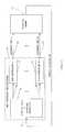
- FIG. 16is a diagram of an ECU software architecture 71 .
- Sensor information 72may be input to a special mode and setpoint generator 73 .
- a number N outputs one through N, 74 , 75 from generator 73may go to a number N of sub-controllers one through N, 76 , 77 , respectively.
- a number N outputs 78 , 79 from N sub-controllers 76 , 77may go as actuator sets 1 through N to a physical plant 64 .
- the physical plant 64for example, may be an automotive engine.
- Physical plant 64may have an output which may provide the sensor information 72 to generator 73 .
- Examples of the actuator sets 78 , 79may include fuel injection control, engine brake control, after-treatment control, EGR control, turbocharger control or a combined EGR and turbocharger control, and so forth.
- the particular sub-controllermay be either independent or may interact with other sub-controllers.
- FIG. 17is a diagram of a previous approach for development of new or modified control functions for block 32 .
- Step 51may incorporate development and testing functional blocks in a rapid prototyping (RP) stage.
- a next step 52may be for generating a calibration dataset.
- a stage 53 having steps 16 and 22 , and set 17 of steps 18 , 19 and 21 ,may be necessary for software coding.
- Step 16may be a generating of a functional specification.
- Set 17 of steps 53may include software specification 18 , coding 19 and testing 21 as indicated in FIG. 12 a . Achieving the steps of set 17 might require about six months or so of effort. Whether the effort takes six months or not, the time period for this set 17 may be enormously large relative to the other steps of the system.
- the next step 22may include functional testing.
- a calibration dataset 39may be downloaded to functional block 32 of the ECU 31 as indicated in step 57 . Then in step 58 , there may be an iteration on calibration while working on the engine. At an evaluation step 59 , a check may be done to determine whether the calibration is acceptable. If not, then an iteration 61 may be fed back to step 51 where the process of steps 51 , 52 , 16 , 17 , 22 , 57 and 58 may be repeated resulting in another large amount of spent time. The iteration 61 may be repeated until the functional block and calibration are deemed acceptable at step 59 .
- FIG. 18 areveals the present approach for obtaining new control functions being time-saving particularly for iteration 61 .
- the laborious software stage 53may be circumvented by iteration 61 .
- stage 53may involve integrating the MPC controller template functional block 42 into the ECU 31 software.
- the MPC controllermay be configurable through the calibration dataset 39 .
- This stage 53may involve generating a functional specification at step 16 , steps of software specification 18 , coding 19 and testing 21 (as shown in FIG. 12 b ) at set 17 and then functional testing at step 22 .
- set 17 of stepsmay take about six or so months.
- Onemay continue on from stage 53 to step 51 where there are developing and testing functional blocks in the rapid prototyping stage.
- step 52there may be a generating of the calibration dataset 39 .
- the calibration dataset 39may be downloaded, as indicated in step 57 , to ECU 31 having the MPC controller template in function block 42 .
- a step 58may indicate iterating on calibration while working on the physical plant such as an engine.
- an outcome of step 58may be evaluated as acceptable or not acceptable.
- Another key aspect of the present systemis that if the outcome of step 58 is evaluated as unacceptable, then iteration 61 may proceed directly to step 51 in that there is not necessarily a need to repeat stage 53 (like the approach of FIG. 17 ).
- the present sequencemay go from step 51 through steps 52 , 57 and 58 , and to step 59 where the outcome of step 58 may be evaluated again. Iteration 61 appears very much quicker than the iteration in FIG. 17 since in FIG.
- the lengthy software coding step 19 (noted in FIG. 12 b ) of set 17may be moved out of the iteration loop 61 after the just one-time initial coding, or coding change.
- the present approachmay permit movement of the coding step 19 (including the other steps in set 17 and stage 53 ) upstream from step 51 and entry of iteration loop 61 in the overall software development process.
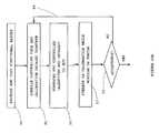
- FIG. 18 bis a diagram of a developmental approach of the present invention that compiles a controller algorithm and a dataset together.
- a step 94may include developing and testing functional blocks. Then a step 95 may occur for compiling controller code and a calibration dataset together. Downloading an MPC controller (algorithm and dataset) to an ECU may be step 96 . Step 97 may include iterating on calibration while working on the engine. Then a question as to whether the result of this approach is acceptable at step 98 . If not, an iteration 99 may return the approach back to step 95 to repeat steps 95 through 98 . This iteration may continue indefinitely until there an acceptance at step 98 .
Landscapes
- Engineering & Computer Science (AREA)
- Physics & Mathematics (AREA)
- Automation & Control Theory (AREA)
- General Physics & Mathematics (AREA)
- Computer Vision & Pattern Recognition (AREA)
- Medical Informatics (AREA)
- Software Systems (AREA)
- Evolutionary Computation (AREA)
- Health & Medical Sciences (AREA)
- Artificial Intelligence (AREA)
- General Engineering & Computer Science (AREA)
- Feedback Control In General (AREA)
- Stored Programmes (AREA)
- Management, Administration, Business Operations System, And Electronic Commerce (AREA)
Abstract
Description
xk+1=Axk+Buk
yk=Cxk+Duk (1.1)
where, x ε

Using simplified notation, equations (1.2) and (1.3) may be written as
and Pxx, Pux, Pxy, Puyare corresponding matrices.
where, Q ε
where, ek=yk−rkis the tracking error, rkis the reference signal and Δuk=uk−uk−1.
where, H and F represent corresponding matrices and G, W and V represent matrices defining constraints. Then, the control action at each sampling period may be obtained by solving the optimization problem of equation (1.7).
z={right arrow over (u)}+H−1FTxk (1.8)
where, z represents the new optimization vector of appropriate size. The new optimization problem may generally be given by the following equation (1.9):
The associated Lagrange function may be defined as
where, λ ε
Hz+GTλ=0,
Gz−W−Sxk≦0,
λi
λi
where, iArepresents a set of indices of all active constraints. If I is the set of indices of all constraints and z*(xk) is the optimal solution to (1.9), then, iAmay be defined by the following equation (1.12):
iA(xk)

Similarly, the set of inactive constraints can be defined by equation (1.13):
iNA(xk)
Using the KKT conditions of equation (1.11), for optimal solution z*(xk) it may hold then:
Hz*(xk)+Gi
Gi
Gi
λ*i
λ*i
Utilizing the first condition in equation (1.14) and assuming that matrix H

z*(xk)=−H−1Gi
Using equation (1.15) and second condition in (1.14), λ*i
λ*i
and the optimal solution may be expressed as affine function of parameter vector xk
z*(xk)=H−1Gi
{right arrow over (u)}*(xk)=−H−1FTxk+z*(xk) (1.19)
Therefore, the solution of the optimization problem (1.9) may be divided into the off-line part and on-line part.
where the notation A(1 . . . n )is used to denote the first n rows of matrix A.
Hz*(xk)+Gi
Gi
Gi
λ*i
λ*i
The vector of optimal Lagrange multipliers may be given by
λ*i
Then, the optimal solution may given by
z*(xk)=−H−1Gi
M1j=−(Gi
M2j=−(Gi
M3j=−H−1Gi
M4=(−H−1FT)(1 . . . n
M5=G
M6=W
M7=S (1.24)
as shown in
block911. If vector z(xk) is primal feasible, then set z*(xk)=z(xk) and compute the optimal control action as uk*(xk)=uk(xk)−(z*(xk))(1 . . . n
and the parameter vector xkis constrained by
Then, the number of feasible combinations of active constraints may be n=3 (a case with all inactive constraints is not included), and the feasible combinations may be {(1), (4), (1,4)}. The following matrices (see (1.24)) may be stored according to the off-line part of the control algorithm,
The stored matrices from (1.27) to (1.31) may be utilized in the on-line part of the primal-dual feasibility algorithm to find the optimal solution for the given parameter vector xk.
u*j(xk)=M2jxk+m2j, j=1,2, . . . ,n (1.32)
M2j=(−H−1F+H−1Gi
m2j=(H−1Gi
Claims (23)
Priority Applications (5)
| Application Number | Priority Date | Filing Date | Title |
|---|---|---|---|
| US12/174,910US8060290B2 (en) | 2008-07-17 | 2008-07-17 | Configurable automotive controller |
| EP17184543.1AEP3264204B1 (en) | 2008-07-17 | 2009-07-02 | A configurable automotive controller |
| EP09164481.5AEP2146258B1 (en) | 2008-07-17 | 2009-07-02 | A configurable automotive controller |
| US12/886,486US7996140B2 (en) | 2008-07-17 | 2010-09-20 | Configurable automotive controller |
| US13/179,252US8265854B2 (en) | 2008-07-17 | 2011-07-08 | Configurable automotive controller |
Applications Claiming Priority (1)
| Application Number | Priority Date | Filing Date | Title |
|---|---|---|---|
| US12/174,910US8060290B2 (en) | 2008-07-17 | 2008-07-17 | Configurable automotive controller |
Related Child Applications (1)
| Application Number | Title | Priority Date | Filing Date |
|---|---|---|---|
| US12/886,486ContinuationUS7996140B2 (en) | 2008-07-17 | 2010-09-20 | Configurable automotive controller |
Publications (2)
| Publication Number | Publication Date |
|---|---|
| US20100017094A1 US20100017094A1 (en) | 2010-01-21 |
| US8060290B2true US8060290B2 (en) | 2011-11-15 |
Family
ID=41211713
Family Applications (3)
| Application Number | Title | Priority Date | Filing Date |
|---|---|---|---|
| US12/174,910Active2028-11-19US8060290B2 (en) | 2008-07-17 | 2008-07-17 | Configurable automotive controller |
| US12/886,486ActiveUS7996140B2 (en) | 2008-07-17 | 2010-09-20 | Configurable automotive controller |
| US13/179,252ActiveUS8265854B2 (en) | 2008-07-17 | 2011-07-08 | Configurable automotive controller |
Family Applications After (2)
| Application Number | Title | Priority Date | Filing Date |
|---|---|---|---|
| US12/886,486ActiveUS7996140B2 (en) | 2008-07-17 | 2010-09-20 | Configurable automotive controller |
| US13/179,252ActiveUS8265854B2 (en) | 2008-07-17 | 2011-07-08 | Configurable automotive controller |
Country Status (2)
| Country | Link |
|---|---|
| US (3) | US8060290B2 (en) |
| EP (2) | EP3264204B1 (en) |
Cited By (45)
| Publication number | Priority date | Publication date | Assignee | Title |
|---|---|---|---|---|
| US20110238359A1 (en)* | 2008-09-01 | 2011-09-29 | Avl List Gmbh | Method and Control Arrangement for Controlling a Controlled System with a Repeating Working Cycle |
| US20110301723A1 (en)* | 2010-06-02 | 2011-12-08 | Honeywell International Inc. | Using model predictive control to optimize variable trajectories and system control |
| US20120010732A1 (en)* | 2008-07-17 | 2012-01-12 | Honeywell International Inc. | Configurable automotive controller |
| US8360040B2 (en) | 2005-08-18 | 2013-01-29 | Honeywell International Inc. | Engine controller |
| US9146545B2 (en) | 2012-11-27 | 2015-09-29 | Honeywell International Inc. | Multivariable control system for setpoint design |
| US9170573B2 (en) | 2009-09-24 | 2015-10-27 | Honeywell International Inc. | Method and system for updating tuning parameters of a controller |
| US9235657B1 (en) | 2013-03-13 | 2016-01-12 | Johnson Controls Technology Company | System identification and model development |
| US9436179B1 (en) | 2013-03-13 | 2016-09-06 | Johnson Controls Technology Company | Systems and methods for energy cost optimization in a building system |
| US9650934B2 (en) | 2011-11-04 | 2017-05-16 | Honeywell spol.s.r.o. | Engine and aftertreatment optimization system |
| US9677493B2 (en) | 2011-09-19 | 2017-06-13 | Honeywell Spol, S.R.O. | Coordinated engine and emissions control system |
| US9852481B1 (en) | 2013-03-13 | 2017-12-26 | Johnson Controls Technology Company | Systems and methods for cascaded model predictive control |
| US10036338B2 (en) | 2016-04-26 | 2018-07-31 | Honeywell International Inc. | Condition-based powertrain control system |
| US10101731B2 (en) | 2014-05-01 | 2018-10-16 | Johnson Controls Technology Company | Low level central plant optimization |
| US10106171B2 (en) | 2015-07-28 | 2018-10-23 | Crown Equipment Corporation | Vehicle control module with signal switchboard and output tables |
| US10124750B2 (en) | 2016-04-26 | 2018-11-13 | Honeywell International Inc. | Vehicle security module system |
| US10186889B2 (en) | 2015-10-08 | 2019-01-22 | Taurus Des, Llc | Electrical energy storage system with variable state-of-charge frequency response optimization |
| US10190793B2 (en) | 2015-10-08 | 2019-01-29 | Johnson Controls Technology Company | Building management system with electrical energy storage optimization based on statistical estimates of IBDR event probabilities |
| US10190789B2 (en) | 2015-09-30 | 2019-01-29 | Johnson Controls Technology Company | Central plant with coordinated HVAC equipment staging across multiple subplants |
| US10197632B2 (en) | 2015-10-08 | 2019-02-05 | Taurus Des, Llc | Electrical energy storage system with battery power setpoint optimization using predicted values of a frequency regulation signal |
| US10222427B2 (en) | 2015-10-08 | 2019-03-05 | Con Edison Battery Storage, Llc | Electrical energy storage system with battery power setpoint optimization based on battery degradation costs and expected frequency response revenue |
| US10235479B2 (en) | 2015-05-06 | 2019-03-19 | Garrett Transportation I Inc. | Identification approach for internal combustion engine mean value models |
| US10250039B2 (en) | 2015-10-08 | 2019-04-02 | Con Edison Battery Storage, Llc | Energy storage controller with battery life model |
| US10272779B2 (en) | 2015-08-05 | 2019-04-30 | Garrett Transportation I Inc. | System and approach for dynamic vehicle speed optimization |
| US10283968B2 (en) | 2015-10-08 | 2019-05-07 | Con Edison Battery Storage, Llc | Power control system with power setpoint adjustment based on POI power limits |
| US10309287B2 (en) | 2016-11-29 | 2019-06-04 | Garrett Transportation I Inc. | Inferential sensor |
| US10389136B2 (en) | 2015-10-08 | 2019-08-20 | Con Edison Battery Storage, Llc | Photovoltaic energy system with value function optimization |
| US10418833B2 (en) | 2015-10-08 | 2019-09-17 | Con Edison Battery Storage, Llc | Electrical energy storage system with cascaded frequency response optimization |
| US10415492B2 (en) | 2016-01-29 | 2019-09-17 | Garrett Transportation I Inc. | Engine system with inferential sensor |
| US10418832B2 (en) | 2015-10-08 | 2019-09-17 | Con Edison Battery Storage, Llc | Electrical energy storage system with constant state-of charge frequency response optimization |
| US10423131B2 (en) | 2015-07-31 | 2019-09-24 | Garrett Transportation I Inc. | Quadratic program solver for MPC using variable ordering |
| US10503128B2 (en) | 2015-01-28 | 2019-12-10 | Garrett Transportation I Inc. | Approach and system for handling constraints for measured disturbances with uncertain preview |
| US10554170B2 (en) | 2015-10-08 | 2020-02-04 | Con Edison Battery Storage, Llc | Photovoltaic energy system with solar intensity prediction |
| US10564610B2 (en) | 2015-10-08 | 2020-02-18 | Con Edison Battery Storage, Llc | Photovoltaic energy system with preemptive ramp rate control |
| US10594153B2 (en) | 2016-07-29 | 2020-03-17 | Con Edison Battery Storage, Llc | Frequency response optimization control system |
| US10621291B2 (en) | 2015-02-16 | 2020-04-14 | Garrett Transportation I Inc. | Approach for aftertreatment system modeling and model identification |
| US10700541B2 (en) | 2015-10-08 | 2020-06-30 | Con Edison Battery Storage, Llc | Power control system with battery power setpoint optimization using one-step-ahead prediction |
| US10742055B2 (en) | 2015-10-08 | 2020-08-11 | Con Edison Battery Storage, Llc | Renewable energy system with simultaneous ramp rate control and frequency regulation |
| US10778012B2 (en) | 2016-07-29 | 2020-09-15 | Con Edison Battery Storage, Llc | Battery optimization control system with data fusion systems and methods |
| US10838441B2 (en) | 2017-11-28 | 2020-11-17 | Johnson Controls Technology Company | Multistage HVAC system with modulating device demand control |
| US10838440B2 (en) | 2017-11-28 | 2020-11-17 | Johnson Controls Technology Company | Multistage HVAC system with discrete device selection prioritization |
| US11057213B2 (en) | 2017-10-13 | 2021-07-06 | Garrett Transportation I, Inc. | Authentication system for electronic control unit on a bus |
| US11156180B2 (en) | 2011-11-04 | 2021-10-26 | Garrett Transportation I, Inc. | Integrated optimization and control of an engine and aftertreatment system |
| US11159022B2 (en) | 2018-08-28 | 2021-10-26 | Johnson Controls Tyco IP Holdings LLP | Building energy optimization system with a dynamically trained load prediction model |
| US11163271B2 (en) | 2018-08-28 | 2021-11-02 | Johnson Controls Technology Company | Cloud based building energy optimization system with a dynamically trained load prediction model |
| US11210617B2 (en) | 2015-10-08 | 2021-12-28 | Johnson Controls Technology Company | Building management system with electrical energy storage optimization based on benefits and costs of participating in PDBR and IBDR programs |
Families Citing this family (39)
| Publication number | Priority date | Publication date | Assignee | Title |
|---|---|---|---|---|
| US7467614B2 (en) | 2004-12-29 | 2008-12-23 | Honeywell International Inc. | Pedal position and/or pedal change rate for use in control of an engine |
| US8924331B2 (en)* | 2010-09-03 | 2014-12-30 | Honeywell International Inc. | System and method for solving quadratic programming problems with bound constraints utilizing a semi-explicit quadratic programming solver |
| JP5834759B2 (en) | 2011-02-28 | 2015-12-24 | 富士通株式会社 | Matrix generation program, method and apparatus, and plant control program, method and apparatus |
| US9097197B2 (en)* | 2011-03-31 | 2015-08-04 | Robert Bosch Gmbh | Defining a region of optimization based on engine usage data |
| US8892326B2 (en)* | 2011-10-10 | 2014-11-18 | Bendix Commercial Vehicle Systems Llc | Electronic control unit configuration tool |
| US9200587B2 (en)* | 2012-04-27 | 2015-12-01 | Tula Technology, Inc. | Look-up table based skip fire engine control |
| US9920697B2 (en) | 2014-03-26 | 2018-03-20 | GM Global Technology Operations LLC | Engine control systems and methods for future torque request increases |
| US9347381B2 (en) | 2014-03-26 | 2016-05-24 | GM Global Technology Operations LLC | Model predictive control systems and methods for internal combustion engines |
| US9732688B2 (en) | 2014-03-26 | 2017-08-15 | GM Global Technology Operations LLC | System and method for increasing the temperature of a catalyst when an engine is started using model predictive control |
| US9863345B2 (en) | 2012-11-27 | 2018-01-09 | GM Global Technology Operations LLC | System and method for adjusting weighting values assigned to errors in target actuator values of an engine when controlling the engine using model predictive control |
| US9797318B2 (en)* | 2013-08-02 | 2017-10-24 | GM Global Technology Operations LLC | Calibration systems and methods for model predictive controllers |
| US9541019B2 (en) | 2014-03-26 | 2017-01-10 | GM Global Technology Operations LLC | Estimation systems and methods with model predictive control |
| US9714616B2 (en) | 2014-03-26 | 2017-07-25 | GM Global Technology Operations LLC | Non-model predictive control to model predictive control transitions |
| US9528453B2 (en) | 2014-11-07 | 2016-12-27 | GM Global Technologies Operations LLC | Throttle control systems and methods based on pressure ratio |
| US9765703B2 (en) | 2013-04-23 | 2017-09-19 | GM Global Technology Operations LLC | Airflow control systems and methods using model predictive control |
| US9605615B2 (en) | 2015-02-12 | 2017-03-28 | GM Global Technology Operations LLC | Model Predictive control systems and methods for increasing computational efficiency |
| US9784198B2 (en) | 2015-02-12 | 2017-10-10 | GM Global Technology Operations LLC | Model predictive control systems and methods for increasing computational efficiency |
| US9587573B2 (en) | 2014-03-26 | 2017-03-07 | GM Global Technology Operations LLC | Catalyst light off transitions in a gasoline engine using model predictive control |
| US9599049B2 (en) | 2014-06-19 | 2017-03-21 | GM Global Technology Operations LLC | Engine speed control systems and methods |
| DE102015103622B4 (en)* | 2014-03-26 | 2020-08-13 | GM Global Technology Operations LLC (n. d. Gesetzen des Staates Delaware) | Model prediction method for internal combustion engines with spark ignition |
| US9683505B2 (en)* | 2014-06-09 | 2017-06-20 | Ford Global Technologies, Llc | Identification and rejection of asymmetric faults |
| CN107076638B (en) | 2014-10-28 | 2019-10-25 | 康明斯排放处理公司 | SCR conversion efficiency diagnosis |
| US10360321B2 (en)* | 2015-03-02 | 2019-07-23 | Fujitsu Limited | Model generation method and information processing apparatus |
| JP6169655B2 (en) | 2015-07-30 | 2017-07-26 | ファナック株式会社 | Machine tool, simulation device, and machine learning device |
| IL241683B (en) | 2015-09-17 | 2020-09-30 | Israel Aerospace Ind Ltd | Multistage turbocharging system |
| JP6077617B1 (en) | 2015-09-25 | 2017-02-08 | ファナック株式会社 | Machine tools that generate optimal speed distribution |
| JP6219897B2 (en)* | 2015-09-28 | 2017-10-25 | ファナック株式会社 | Machine tools that generate optimal acceleration / deceleration |
| US20170220033A1 (en)* | 2016-01-28 | 2017-08-03 | Honeywell International, Inc. | System and method for interactive adjustment of a model predictive controller in an embedded execution environment |
| US9938908B2 (en) | 2016-06-14 | 2018-04-10 | GM Global Technology Operations LLC | System and method for predicting a pedal position based on driver behavior and controlling one or more engine actuators based on the predicted pedal position |
| US10190522B2 (en)* | 2016-06-17 | 2019-01-29 | Toyota Motor Engineering & Manufacturing North America, Inc. | Hybrid partial and full step quadratic solver for model predictive control of diesel engine air path flow and methods of use |
| US10844795B2 (en)* | 2018-01-10 | 2020-11-24 | Toyota Motor Engineering & Manufacturing North America, Inc. | Feedforward and feedback architecture for air path model predictive control of an internal combustion engine |
| US10969752B1 (en)* | 2018-04-06 | 2021-04-06 | United States Of America As Represented By The Secretary Of The Air Force | System and apparatus for estimating states of a physical system |
| US10422290B1 (en) | 2018-04-13 | 2019-09-24 | Toyota Motor Engineering & Manufacturing North America, Inc. | Supervisory model predictive controller for diesel engine emissions control |
| GB2583383B (en)* | 2019-04-26 | 2021-06-09 | Perkins Engines Co Ltd | Internal combustion engine controller |
| GB2583382B (en)* | 2019-04-26 | 2021-10-27 | Perkins Engines Co Ltd | Internal combustion engine controller |
| JP2021032114A (en)* | 2019-08-22 | 2021-03-01 | トヨタ自動車株式会社 | Vehicle learning control system, vehicle control device, and vehicle learning device |
| JP6970156B2 (en)* | 2019-10-18 | 2021-11-24 | トヨタ自動車株式会社 | Data generation method used for vehicle control, vehicle control device, vehicle control system, in-vehicle device and vehicle learning device |
| US12175808B2 (en) | 2021-04-27 | 2024-12-24 | Garrett Transportation I Inc. | Advanced control framework for automotive systems |
| GB2612357A (en)* | 2021-10-29 | 2023-05-03 | Aptiv Tech Ltd | Testing device, method, and software for testing an automotive controller |
Citations (16)
| Publication number | Priority date | Publication date | Assignee | Title |
|---|---|---|---|---|
| EP0301527A2 (en) | 1987-07-28 | 1989-02-01 | Brigham Young University | Device and method for correction of robot inaccuracy |
| US6571191B1 (en) | 1998-10-27 | 2003-05-27 | Cummins, Inc. | Method and system for recalibration of an electronic control module |
| US20060137347A1 (en) | 2004-12-29 | 2006-06-29 | Stewart Gregory E | Coordinated multivariable control of fuel and air in engines |
| US20060137340A1 (en) | 2004-12-29 | 2006-06-29 | Stewart Gregory E | Method and system for using a measure of fueling rate in the air side control of an engine |
| US20060137346A1 (en) | 2004-12-29 | 2006-06-29 | Stewart Gregory E | Multivariable control for an engine |
| US20060137335A1 (en) | 2004-12-29 | 2006-06-29 | Stewart Gregory E | Pedal position and/or pedal change rate for use in control of an engine |
| US20060213184A1 (en) | 2005-03-24 | 2006-09-28 | Honyewll International Inc. | Engine exhaust heat exchanger |
| US20060287795A1 (en) | 2005-06-17 | 2006-12-21 | Tariq Samad | Distributed control architecture for powertrains |
| US7155334B1 (en) | 2005-09-29 | 2006-12-26 | Honeywell International Inc. | Use of sensors in a state observer for a diesel engine |
| US20070039589A1 (en) | 2005-08-18 | 2007-02-22 | Stewart Gregory E | Emissions sensors for fuel control in engines |
| US20070101977A1 (en) | 2004-12-29 | 2007-05-10 | Honeywell International Inc. | Method and system for using a measure of fueling rate in the air side control of an engine |
| US20070142932A1 (en) | 2005-12-15 | 2007-06-21 | Honeywell Asca, Inc. | Technique for switching between controllers |
| US20070151243A1 (en) | 2005-12-30 | 2007-07-05 | Honeywell International Inc. | Control of dual stage turbocharging |
| US20070156363A1 (en) | 2005-12-29 | 2007-07-05 | Stewart Gregory E | Calibration of engine control systems |
| US7302937B2 (en)* | 2005-04-29 | 2007-12-04 | Gm Global Technology Operations, Inc. | Calibration of model-based fuel control for engine start and crank to run transition |
| US7627843B2 (en)* | 2005-03-23 | 2009-12-01 | International Business Machines Corporation | Dynamically interleaving randomly generated test-cases for functional verification |
Family Cites Families (348)
| Publication number | Priority date | Publication date | Assignee | Title |
|---|---|---|---|---|
| GB1356565A (en) | 1970-09-04 | 1974-06-12 | Ricardo & Co Engineers | Limitting exhaust smoke emission from i c engines |
| US4055158A (en) | 1974-04-08 | 1977-10-25 | Ethyl Corporation | Exhaust recirculation |
| US4005578A (en) | 1975-03-31 | 1977-02-01 | The Garrett Corporation | Method and apparatus for turbocharger control |
| JPS5920865B2 (en) | 1977-07-01 | 1984-05-16 | 株式会社日立製作所 | EGR mechanism of engine with turbo gear |
| DE2803750A1 (en) | 1978-01-28 | 1979-08-02 | Bosch Gmbh Robert | PROCEDURE AND EQUIPMENT FOR FUEL MEASUREMENT IN COMBUSTION ENGINE |
| US4252098A (en) | 1978-08-10 | 1981-02-24 | Chrysler Corporation | Air/fuel ratio control for an internal combustion engine using an exhaust gas sensor |
| US4426982A (en) | 1980-10-08 | 1984-01-24 | Friedmann & Maier Aktiengesellschaft | Process for controlling the beginning of delivery of a fuel injection pump and device for performing said process |
| US4438497A (en) | 1981-07-20 | 1984-03-20 | Ford Motor Company | Adaptive strategy to control internal combustion engine |
| US4383441A (en) | 1981-07-20 | 1983-05-17 | Ford Motor Company | Method for generating a table of engine calibration control values |
| JPS5835255A (en) | 1981-08-27 | 1983-03-01 | Toyota Motor Corp | Diesel engine exhaust gas recirculation device |
| US4456883A (en) | 1982-10-04 | 1984-06-26 | Ambac Industries, Incorporated | Method and apparatus for indicating an operating characteristic of an internal combustion engine |
| US4485794A (en) | 1982-10-04 | 1984-12-04 | United Technologies Diesel Systems, Inc. | Method and apparatus for controlling diesel engine exhaust gas recirculation partly as a function of exhaust particulate level |
| US4616308A (en) | 1983-11-15 | 1986-10-07 | Shell Oil Company | Dynamic process control |
| US4601270A (en) | 1983-12-27 | 1986-07-22 | United Technologies Diesel Systems, Inc. | Method and apparatus for torque control of an internal combustion engine as a function of exhaust smoke level |
| NL8400271A (en)* | 1984-01-30 | 1985-08-16 | Philips Nv | CONTROL DEVICE FOR A COMBUSTION ENGINE. |
| JPS60163731A (en) | 1984-02-07 | 1985-08-26 | Nissan Motor Co Ltd | Vehicle speed control device |
| JPH0737771B2 (en) | 1984-02-07 | 1995-04-26 | 日産自動車株式会社 | Slot control device |
| JPH0697003B2 (en) | 1984-12-19 | 1994-11-30 | 日本電装株式会社 | Internal combustion engine operating condition control device |
| JPH0672563B2 (en) | 1986-04-28 | 1994-09-14 | マツダ株式会社 | Engine throttle control device |
| JPS647935A (en) | 1987-06-30 | 1989-01-11 | Nissan Motor | Catalytic converter device |
| GB8807676D0 (en)* | 1988-03-31 | 1988-05-05 | Westland Helicopters | Helicopter control systems |
| US5123397A (en) | 1988-07-29 | 1992-06-23 | North American Philips Corporation | Vehicle management computer |
| GB8825213D0 (en) | 1988-10-27 | 1988-11-30 | Lucas Ind Plc | Control system for i c engine |
| DE3930396C2 (en) | 1989-09-12 | 1993-11-04 | Bosch Gmbh Robert | METHOD FOR ADJUSTING AIR AND FUEL AMOUNTS FOR A MULTI-CYLINDRICAL INTERNAL COMBUSTION ENGINE |
| US5076237A (en) | 1990-01-11 | 1991-12-31 | Barrack Technology Limited | Means and method for measuring and controlling smoke from an internal combustion engine |
| US5089236A (en) | 1990-01-19 | 1992-02-18 | Cummmins Engine Company, Inc. | Variable geometry catalytic converter |
| US5394322A (en) | 1990-07-16 | 1995-02-28 | The Foxboro Company | Self-tuning controller that extracts process model characteristics |
| US5150289A (en) | 1990-07-30 | 1992-09-22 | The Foxboro Company | Method and apparatus for process control |
| US5293553A (en) | 1991-02-12 | 1994-03-08 | General Motors Corporation | Software air-flow meter for an internal combustion engine |
| US5273019A (en) | 1990-11-26 | 1993-12-28 | General Motors Corporation | Apparatus with dynamic prediction of EGR in the intake manifold |
| US5270935A (en) | 1990-11-26 | 1993-12-14 | General Motors Corporation | Engine with prediction/estimation air flow determination |
| US5094213A (en) | 1991-02-12 | 1992-03-10 | General Motors Corporation | Method for predicting R-step ahead engine state measurements |
| JPH0565845A (en) | 1991-03-06 | 1993-03-19 | Hitachi Ltd | Engine control method and system |
| US5186081A (en) | 1991-06-07 | 1993-02-16 | General Motors Corporation | Method of regulating supercharger boost pressure |
| JP3076417B2 (en) | 1991-07-23 | 2000-08-14 | マツダ株式会社 | Engine exhaust purification device |
| ZA928107B (en) | 1991-10-23 | 1993-05-07 | Transcom Gas Tech | Boost pressure control. |
| US5349816A (en) | 1992-02-20 | 1994-09-27 | Mitsubishi Jidosha Kogyo Kabushiki Kaisha | Exhaust emission control system |
| DE69300645T2 (en) | 1992-03-25 | 1996-04-11 | Toyota Motor Co Ltd | Device for removing NOx for an internal combustion engine. |
| US5398502A (en) | 1992-05-27 | 1995-03-21 | Fuji Jukogyo Kabushiki Kaisha | System for controlling a valve mechanism for an internal combustion engine |
| US6171556B1 (en) | 1992-11-12 | 2001-01-09 | Engelhard Corporation | Method and apparatus for treating an engine exhaust gas stream |
| ZA939334B (en) | 1992-12-14 | 1994-10-03 | Transcom Gas Tecnologies Pty L | Engine control unit |
| US5408406A (en) | 1993-10-07 | 1995-04-18 | Honeywell Inc. | Neural net based disturbance predictor for model predictive control |
| JP3577728B2 (en) | 1993-12-03 | 2004-10-13 | 株式会社デンソー | Air-fuel ratio control device for internal combustion engine |
| US5431139A (en) | 1993-12-23 | 1995-07-11 | Ford Motor Company | Air induction control system for variable displacement internal combustion engine |
| JPH07259621A (en) | 1994-03-18 | 1995-10-09 | Mitsubishi Motors Corp | Fuel supply control device for internal combustion engine |
| US5452576A (en) | 1994-08-09 | 1995-09-26 | Ford Motor Company | Air/fuel control with on-board emission measurement |
| US5611198A (en) | 1994-08-16 | 1997-03-18 | Caterpillar Inc. | Series combination catalytic converter |
| US5704011A (en) | 1994-11-01 | 1997-12-30 | The Foxboro Company | Method and apparatus for providing multivariable nonlinear control |
| US5642502A (en) | 1994-12-06 | 1997-06-24 | University Of Central Florida | Method and system for searching for relevant documents from a text database collection, using statistical ranking, relevancy feedback and small pieces of text |
| DE19505431B4 (en) | 1995-02-17 | 2010-04-29 | Bayerische Motoren Werke Aktiengesellschaft | Power control system for motor vehicles with a plurality of power converting components |
| US5702754A (en) | 1995-02-22 | 1997-12-30 | Meadox Medicals, Inc. | Method of providing a substrate with a hydrophilic coating and substrates, particularly medical devices, provided with such coatings |
| US5560208A (en) | 1995-07-28 | 1996-10-01 | Halimi; Edward M. | Motor-assisted variable geometry turbocharging system |
| US5690086A (en) | 1995-09-11 | 1997-11-25 | Nissan Motor Co., Ltd. | Air/fuel ratio control apparatus |
| US6236956B1 (en) | 1996-02-16 | 2001-05-22 | Avant! Corporation | Component-based analog and mixed-signal simulation model development including newton step manager |
| DE19607862C2 (en) | 1996-03-01 | 1998-10-29 | Volkswagen Ag | Processes and devices for exhaust gas purification |
| US5765533A (en) | 1996-04-18 | 1998-06-16 | Nissan Motor Co., Ltd. | Engine air-fuel ratio controller |
| US7149590B2 (en) | 1996-05-06 | 2006-12-12 | Pavilion Technologies, Inc. | Kiln control and upset recovery using a model predictive control in series with forward chaining |
| US5692478A (en) | 1996-05-07 | 1997-12-02 | Hitachi America, Ltd., Research And Development Division | Fuel control system for a gaseous fuel internal combustion engine with improved fuel metering and mixing means |
| IT1286101B1 (en)* | 1996-06-17 | 1998-07-07 | Same Spa Ora Same Deutz Fahr S | ELECTRONIC DEVICE FOR REGULATING THE ROTATION SPEED OF THE MOTOR OF AN AGRICULTURAL TRACTOR |
| JPH1071325A (en) | 1996-06-21 | 1998-03-17 | Ngk Insulators Ltd | Method for controlling engine exhaust gas system and method for detecting deterioration in catalyst/ adsorption means |
| DE19628796C1 (en) | 1996-07-17 | 1997-10-23 | Daimler Benz Ag | System for removal of nitrogen oxide(s), carbon mon:oxide, etc. from engine exhaust gases |
| US5846157A (en) | 1996-10-25 | 1998-12-08 | General Motors Corporation | Integrated control of a lean burn engine and a continuously variable transmission |
| US6208914B1 (en) | 1996-11-21 | 2001-03-27 | Barron Associates, Inc. | System for improved receding-horizon adaptive and reconfigurable control |
| US5785030A (en) | 1996-12-17 | 1998-07-28 | Dry Systems Technologies | Exhaust gas recirculation in internal combustion engines |
| JPH10184417A (en) | 1996-12-25 | 1998-07-14 | Hitachi Ltd | Control device for in-cylinder injection internal combustion engine |
| DE59700614D1 (en) | 1997-02-08 | 1999-12-02 | Volkswagen Ag | Formed part with a multiple sheet metal structure |
| EP1077375B1 (en) | 1997-03-21 | 2012-06-20 | Ngk Spark Plug Co., Ltd | Method and apparatus for measuring NOx gas concentration |
| US6105365A (en) | 1997-04-08 | 2000-08-22 | Engelhard Corporation | Apparatus, method, and system for concentrating adsorbable pollutants and abatement thereof |
| DE19716916A1 (en) | 1997-04-23 | 1998-10-29 | Porsche Ag | ULEV concept for high-performance engines |
| US6122555A (en) | 1997-05-05 | 2000-09-19 | Honeywell International Inc. | System and methods for globally optimizing a process facility |
| JP3237607B2 (en) | 1997-05-26 | 2001-12-10 | トヨタ自動車株式会社 | Catalyst poisoning regeneration equipment for internal combustion engines |
| US5970075A (en) | 1997-06-18 | 1999-10-19 | Uniden San Diego Research And Development Center Inc. | Method and apparatus for generating an error location polynomial table |
| US5746183A (en) | 1997-07-02 | 1998-05-05 | Ford Global Technologies, Inc. | Method and system for controlling fuel delivery during transient engine conditions |
| US5771867A (en) | 1997-07-03 | 1998-06-30 | Caterpillar Inc. | Control system for exhaust gas recovery system in an internal combustion engine |
| US5995895A (en)* | 1997-07-15 | 1999-11-30 | Case Corporation | Control of vehicular systems in response to anticipated conditions predicted using predetermined geo-referenced maps |
| SE511791C2 (en) | 1997-07-16 | 1999-11-29 | Foersvarets Forskningsanstalt | New chemical compound suitable for use as an explosive and intermediate product and preparation method for the compound |
| JP3799758B2 (en) | 1997-08-05 | 2006-07-19 | トヨタ自動車株式会社 | Catalyst regeneration device for internal combustion engine |
| GB9717034D0 (en) | 1997-08-13 | 1997-10-15 | Johnson Matthey Plc | Improvements in emissions control |
| US5974788A (en) | 1997-08-29 | 1999-11-02 | Ford Global Technologies, Inc. | Method and apparatus for desulfating a nox trap |
| US6466893B1 (en) | 1997-09-29 | 2002-10-15 | Fisher Controls International, Inc. | Statistical determination of estimates of process control loop parameters |
| US6804618B2 (en) | 1997-09-29 | 2004-10-12 | Fisher Controls International, Llc | Detection and discrimination of instabilities in process control loops |
| US6453308B1 (en) | 1997-10-01 | 2002-09-17 | Aspen Technology, Inc. | Non-linear dynamic predictive device |
| DE19848564C2 (en) | 1997-10-29 | 2000-11-16 | Mitsubishi Motors Corp | Cooling device for recirculated exhaust gas |
| DE19747670C1 (en) | 1997-10-29 | 1998-12-10 | Daimler Benz Ag | Exhaust gas cleaning system for internal combustion engine |
| US5942195A (en) | 1998-02-23 | 1999-08-24 | General Motors Corporation | Catalytic plasma exhaust converter |
| US6237330B1 (en) | 1998-04-15 | 2001-05-29 | Nissan Motor Co., Ltd. | Exhaust purification device for internal combustion engine |
| US6436005B1 (en) | 1998-06-18 | 2002-08-20 | Cummins, Inc. | System for controlling drivetrain components to achieve fuel efficiency goals |
| US6327361B1 (en) | 1998-07-13 | 2001-12-04 | Lucent Technologies Inc. | Multivariate rate-based overload control for multiple-class communications traffic |
| US6055810A (en) | 1998-08-14 | 2000-05-02 | Chrysler Corporation | Feedback control of direct injected engines by use of a smoke sensor |
| US6725208B1 (en) | 1998-10-06 | 2004-04-20 | Pavilion Technologies, Inc. | Bayesian neural networks for optimization and control |
| US6216083B1 (en) | 1998-10-22 | 2001-04-10 | Yamaha Motor Co., Ltd. | System for intelligent control of an engine based on soft computing |
| US6560958B1 (en) | 1998-10-29 | 2003-05-13 | Massachusetts Institute Of Technology | Emission abatement system |
| DE19856367C1 (en) | 1998-12-07 | 2000-06-21 | Siemens Ag | Process for cleaning the exhaust gas with lambda control |
| SE519922C2 (en) | 1998-12-07 | 2003-04-29 | Stt Emtec Ab | Device and process for exhaust purification and use of the device |
| US6089019A (en) | 1999-01-15 | 2000-07-18 | Borgwarner Inc. | Turbocharger and EGR system |
| DE19902209A1 (en) | 1999-01-21 | 2000-07-27 | Bosch Gmbh Robert | Combustion knock prevention device for operation of internal combustion, uses dynamic phase based correction |
| JP3680650B2 (en) | 1999-01-25 | 2005-08-10 | トヨタ自動車株式会社 | Exhaust gas purification device for internal combustion engine |
| US6067800A (en) | 1999-01-26 | 2000-05-30 | Ford Global Technologies, Inc. | Control method for a variable geometry turbocharger in a diesel engine having exhaust gas recirculation |
| US6178749B1 (en) | 1999-01-26 | 2001-01-30 | Ford Motor Company | Method of reducing turbo lag in diesel engines having exhaust gas recirculation |
| US6076353A (en) | 1999-01-26 | 2000-06-20 | Ford Global Technologies, Inc. | Coordinated control method for turbocharged diesel engines having exhaust gas recirculation |
| US6035640A (en) | 1999-01-26 | 2000-03-14 | Ford Global Technologies, Inc. | Control method for turbocharged diesel engines having exhaust gas recirculation |
| JP4158268B2 (en) | 1999-03-17 | 2008-10-01 | 日産自動車株式会社 | Engine exhaust purification system |
| US6470886B1 (en) | 1999-03-23 | 2002-10-29 | Creations By B J H, Llc | Continuous positive airway pressure headgear |
| JP2000282848A (en) | 1999-03-30 | 2000-10-10 | Nissan Motor Co Ltd | Exhaust gas purification device for internal combustion engine |
| US6279551B1 (en) | 1999-04-05 | 2001-08-28 | Nissan Motor Co., Ltd. | Apparatus for controlling internal combustion engine with supercharging device |
| US6205786B1 (en) | 1999-06-16 | 2001-03-27 | Caterpillar Inc. | Engine having increased boost at low engine speeds |
| US6662058B1 (en) | 1999-06-28 | 2003-12-09 | Sanchez Juan Martin | Adaptive predictive expert control system |
| US6301888B1 (en) | 1999-07-22 | 2001-10-16 | The United States Of America As Represented By The Administrator Of The Environmental Protection Agency | Low emission, diesel-cycle engine |
| JP3684934B2 (en) | 1999-08-30 | 2005-08-17 | 三菱自動車工業株式会社 | Exhaust gas purification device for internal combustion engine |
| JP3549779B2 (en) | 1999-09-17 | 2004-08-04 | 日野自動車株式会社 | Internal combustion engine |
| US6445963B1 (en) | 1999-10-04 | 2002-09-03 | Fisher Rosemount Systems, Inc. | Integrated advanced control blocks in process control systems |
| JP2001107779A (en) | 1999-10-07 | 2001-04-17 | Toyota Motor Corp | Air-fuel ratio control device for internal combustion engine |
| DE60008997T2 (en) | 1999-10-12 | 2004-09-02 | Honda Giken Kogyo K.K. | System for controlling the exhaust gas emissions of an internal combustion engine |
| JP3817991B2 (en) | 1999-10-15 | 2006-09-06 | 日産自動車株式会社 | Control device for internal combustion engine |
| US6233922B1 (en) | 1999-11-23 | 2001-05-22 | Delphi Technologies, Inc. | Engine fuel control with mixed time and event based A/F ratio error estimator and controller |
| JP3743607B2 (en) | 1999-12-02 | 2006-02-08 | 株式会社デンソー | Control device for internal combustion engine |
| DE60034962T2 (en) | 1999-12-14 | 2008-01-24 | Cooper-Standard Automotive Inc., Findlay | INTEGRATED EXHAUST GAS RECOVERY VALVE |
| DE19960166A1 (en) | 1999-12-14 | 2001-06-21 | Fev Motorentech Gmbh | Method for regulating the boost pressure on a piston internal combustion engine with a turbocharger |
| US6273060B1 (en) | 2000-01-11 | 2001-08-14 | Ford Global Technologies, Inc. | Method for improved air-fuel ratio control |
| US6242873B1 (en) | 2000-01-31 | 2001-06-05 | Azure Dynamics Inc. | Method and apparatus for adaptive hybrid vehicle control |
| JP3706785B2 (en) | 2000-02-02 | 2005-10-19 | 本田技研工業株式会社 | Evaporative fuel processing equipment |
| US6539299B2 (en) | 2000-02-18 | 2003-03-25 | Optimum Power Technology | Apparatus and method for calibrating an engine management system |
| US6311484B1 (en) | 2000-02-22 | 2001-11-06 | Engelhard Corporation | System for reducing NOx transient emission |
| US6360541B2 (en) | 2000-03-03 | 2002-03-26 | Honeywell International, Inc. | Intelligent electric actuator for control of a turbocharger with an integrated exhaust gas recirculation valve |
| US6499293B1 (en) | 2000-03-17 | 2002-12-31 | Ford Global Technologies, Inc. | Method and system for reducing NOx tailpipe emissions of a lean-burn internal combustion engine |
| US6860100B1 (en) | 2000-03-17 | 2005-03-01 | Ford Global Technologies, Llc | Degradation detection method for an engine having a NOx sensor |
| US6560528B1 (en) | 2000-03-24 | 2003-05-06 | Internal Combustion Technologies, Inc. | Programmable internal combustion engine controller |
| US6347619B1 (en) | 2000-03-29 | 2002-02-19 | Deere & Company | Exhaust gas recirculation system for a turbocharged engine |
| US6934931B2 (en) | 2000-04-05 | 2005-08-23 | Pavilion Technologies, Inc. | System and method for enterprise modeling, optimization and control |
| EP1143411A3 (en)* | 2000-04-06 | 2004-11-03 | Siemens VDO Automotive Inc. | Active noise cancellation stability solution |
| US6363715B1 (en) | 2000-05-02 | 2002-04-02 | Ford Global Technologies, Inc. | Air/fuel ratio control responsive to catalyst window locator |
| SE519192C2 (en) | 2000-05-17 | 2003-01-28 | Mecel Ab | Engine control method |
| US6360159B1 (en) | 2000-06-07 | 2002-03-19 | Cummins, Inc. | Emission control in an automotive engine |
| DE10028539A1 (en) | 2000-06-08 | 2001-12-20 | Bosch Gmbh Robert | Internal combustion engine operating process involves running at specific intended fuel rate of fuel air mixture via tank venting valve, determined by control device |
| US7330804B2 (en) | 2000-06-29 | 2008-02-12 | Aspen Technology, Inc. | Computer method and apparatus for constraining a non-linear approximator of an empirical process |
| US6389803B1 (en) | 2000-08-02 | 2002-05-21 | Ford Global Technologies, Inc. | Emission control for improved vehicle performance |
| US6360732B1 (en) | 2000-08-10 | 2002-03-26 | Caterpillar Inc. | Exhaust gas recirculation cooling system |
| DE10040516A1 (en) | 2000-08-18 | 2002-02-28 | Bayerische Motoren Werke Ag | Multi-cylinder internal combustion engine with a device for catalyst heating |
| US6379281B1 (en) | 2000-09-08 | 2002-04-30 | Visteon Global Technologies, Inc. | Engine output controller |
| DE10048238B4 (en) | 2000-09-29 | 2014-09-18 | Daimler Ag | Method for operating a diesel internal combustion engine |
| JP4389372B2 (en) | 2000-09-29 | 2009-12-24 | マツダ株式会社 | Engine fuel control device |
| US6760631B1 (en) | 2000-10-04 | 2004-07-06 | General Electric Company | Multivariable control method and system without detailed prediction model |
| US6415602B1 (en) | 2000-10-16 | 2002-07-09 | Engelhard Corporation | Control system for mobile NOx SCR applications |
| DE50001415D1 (en) | 2000-11-03 | 2003-04-10 | Ford Global Tech Inc | Process for the regeneration of the particle filter of a diesel engine |
| JP4564645B2 (en) | 2000-11-27 | 2010-10-20 | 株式会社キャタラー | Exhaust gas purification catalyst |
| JP3753936B2 (en) | 2000-12-05 | 2006-03-08 | 本田技研工業株式会社 | Exhaust gas purification device for internal combustion engine |
| US6671596B2 (en) | 2000-12-27 | 2003-12-30 | Honda Giken Kogyo Kabushiki Kaisha | Control method for suspension |
| US6612292B2 (en) | 2001-01-09 | 2003-09-02 | Nissan Motor Co., Ltd. | Fuel injection control for diesel engine |
| GB0107774D0 (en) | 2001-03-28 | 2001-05-16 | Ford Global Tech Inc | Fuel metering method for an engine operating with controlled auto-ignition |
| DE10117050C1 (en) | 2001-04-05 | 2002-09-12 | Siemens Ag | Process for purifying I.C. engine exhaust gas comprises using a measuring signal depending on the lambda value of the exhaust gas downstream of the catalyst |
| US6532433B2 (en) | 2001-04-17 | 2003-03-11 | General Electric Company | Method and apparatus for continuous prediction, monitoring and control of compressor health via detection of precursors to rotating stall and surge |
| JP4400003B2 (en) | 2001-04-23 | 2010-01-20 | トヨタ自動車株式会社 | Engine air-fuel ratio control method |
| JP4101475B2 (en) | 2001-05-18 | 2008-06-18 | 本田技研工業株式会社 | Exhaust gas purification device for internal combustion engine |
| EP1399784B1 (en) | 2001-05-25 | 2007-10-31 | Parametric Optimization Solutions Ltd. | Improved process control |
| JP2002364415A (en) | 2001-06-07 | 2002-12-18 | Mazda Motor Corp | Exhaust emission control device for engine |
| US6591605B2 (en) | 2001-06-11 | 2003-07-15 | Ford Global Technologies, Llc | System and method for controlling the air / fuel ratio in an internal combustion engine |
| JP3805648B2 (en) | 2001-06-14 | 2006-08-02 | 三菱電機株式会社 | Engine intake air amount control device |
| US6463733B1 (en) | 2001-06-19 | 2002-10-15 | Ford Global Technologies, Inc. | Method and system for optimizing open-loop fill and purge times for an emission control device |
| US6694244B2 (en) | 2001-06-19 | 2004-02-17 | Ford Global Technologies, Llc | Method for quantifying oxygen stored in a vehicle emission control device |
| US6553754B2 (en) | 2001-06-19 | 2003-04-29 | Ford Global Technologies, Inc. | Method and system for controlling an emission control device based on depletion of device storage capacity |
| US6705084B2 (en) | 2001-07-03 | 2004-03-16 | Honeywell International Inc. | Control system for electric assisted turbocharger |
| JP2003027930A (en) | 2001-07-11 | 2003-01-29 | Komatsu Ltd | Exhaust gas purification device for internal combustion engine |
| AT5579U1 (en) | 2001-07-23 | 2002-08-26 | Avl List Gmbh | Exhaust gas recirculation cooler |
| JP3922980B2 (en) | 2001-07-25 | 2007-05-30 | 本田技研工業株式会社 | Control device |
| US6579206B2 (en) | 2001-07-26 | 2003-06-17 | General Motors Corporation | Coordinated control for a powertrain with a continuously variable transmission |
| DE60236815D1 (en) | 2001-08-17 | 2010-08-05 | Tiax Llc | METHOD FOR CONTROLLING AN INTERNAL COMBUSTION ENGINE WITH COMPRESSION IGNITION AND FUEL AIR PRE-MIXING |
| JP2003065109A (en) | 2001-08-28 | 2003-03-05 | Honda Motor Co Ltd | Air-fuel ratio feedback control device for internal combustion engine |
| KR100504422B1 (en) | 2001-09-07 | 2005-07-29 | 미쓰비시 지도샤 고교(주) | Exhaust emission control device for engine |
| US6688283B2 (en) | 2001-09-12 | 2004-02-10 | Daimlerchrysler Corporation | Engine start strategy |
| JP3927395B2 (en) | 2001-09-28 | 2007-06-06 | 株式会社日立製作所 | Control device for compression ignition engine |
| US6666410B2 (en) | 2001-10-05 | 2003-12-23 | The Charles Stark Draper Laboratory, Inc. | Load relief system for a launch vehicle |
| US7184992B1 (en) | 2001-11-01 | 2007-02-27 | George Mason Intellectual Properties, Inc. | Constrained optimization tool |
| FR2832182B1 (en) | 2001-11-13 | 2004-11-26 | Peugeot Citroen Automobiles Sa | ASSISTANCE SYSTEM FOR THE REGENERATION OF EMISSION CONTROL MEASURES INTEGRATED IN AN EXHAUST SYSTEM OF A MOTOR VEHICLE |
| JP2003148198A (en) | 2001-11-13 | 2003-05-21 | Toyota Motor Corp | Exhaust purification device for internal combustion engine |
| US20040006973A1 (en) | 2001-11-21 | 2004-01-15 | Makki Imad Hassan | System and method for controlling an engine |
| US7082753B2 (en) | 2001-12-03 | 2006-08-01 | Catalytica Energy Systems, Inc. | System and methods for improved emission control of internal combustion engines using pulsed fuel flow |
| BR0214668A2 (en) | 2001-12-03 | 2011-07-05 | Catalytica Energy Sys Inc | system and methods for improved internal combustion engine emission control |
| US6601387B2 (en) | 2001-12-05 | 2003-08-05 | Detroit Diesel Corporation | System and method for determination of EGR flow rate |
| US6671603B2 (en) | 2001-12-21 | 2003-12-30 | Daimlerchrysler Corporation | Efficiency-based engine, powertrain and vehicle control |
| KR100482059B1 (en) | 2001-12-24 | 2005-04-13 | 현대자동차주식회사 | Air flux variable charge motion device of engine in vehicle |
| US6920865B2 (en) | 2002-01-29 | 2005-07-26 | Daimlerchrysler Corporation | Mechatronic vehicle powertrain control system |
| GB2388922B (en) | 2002-01-31 | 2005-06-08 | Cambridge Consultants | Control system |
| US6698663B2 (en)* | 2002-02-04 | 2004-03-02 | Delphi Technologies, Inc. | Model-based method of generating control algorithms for an automatic climate control system |
| DE10205380A1 (en) | 2002-02-09 | 2003-08-21 | Daimler Chrysler Ag | Method and device for treating diesel exhaust |
| JP3973922B2 (en) | 2002-02-15 | 2007-09-12 | 本田技研工業株式会社 | Control device |
| JP4061467B2 (en) | 2002-03-15 | 2008-03-19 | 三菱自動車工業株式会社 | Exhaust gas purification device for internal combustion engine |
| US6687597B2 (en) | 2002-03-28 | 2004-02-03 | Saskatchewan Research Council | Neural control system and method for alternatively fueled engines |
| DE10215406B4 (en) | 2002-04-08 | 2015-06-11 | Robert Bosch Gmbh | Method and device for controlling a motor |
| EP1355209A1 (en) | 2002-04-18 | 2003-10-22 | Ford Global Technologies, LLC | Vehicle control system |
| DE10219832B4 (en) | 2002-05-03 | 2005-12-01 | Daimlerchrysler Ag | Method for coding control devices in means of transport |
| JP4144251B2 (en) | 2002-05-09 | 2008-09-03 | トヨタ自動車株式会社 | Control of exhaust gas recirculation in internal combustion engines. |
| JP2003336549A (en) | 2002-05-20 | 2003-11-28 | Denso Corp | Egr device for internal combustion engine |
| US7168239B2 (en) | 2002-06-04 | 2007-01-30 | Ford Global Technologies, Llc | Method and system for rapid heating of an emission control device |
| US6736120B2 (en) | 2002-06-04 | 2004-05-18 | Ford Global Technologies, Llc | Method and system of adaptive learning for engine exhaust gas sensors |
| US6769398B2 (en) | 2002-06-04 | 2004-08-03 | Ford Global Technologies, Llc | Idle speed control for lean burn engine with variable-displacement-like characteristic |
| US7111450B2 (en) | 2002-06-04 | 2006-09-26 | Ford Global Technologies, Llc | Method for controlling the temperature of an emission control device |
| US7505879B2 (en) | 2002-06-05 | 2009-03-17 | Tokyo Electron Limited | Method for generating multivariate analysis model expression for processing apparatus, method for executing multivariate analysis of processing apparatus, control device of processing apparatus and control system for processing apparatus |
| SE522691C3 (en) | 2002-06-12 | 2004-04-07 | Abb Ab | Dynamic on-line optimization of production processes |
| US6941033B2 (en) | 2002-06-25 | 2005-09-06 | National Research Council Of Canada | Method and device for manipulating microscopic quantities of material |
| US6928817B2 (en) | 2002-06-28 | 2005-08-16 | Honeywell International, Inc. | Control system for improved transient response in a variable-geometry turbocharger |
| JP4144272B2 (en) | 2002-07-10 | 2008-09-03 | トヨタ自動車株式会社 | Fuel injection amount control device for internal combustion engine |
| US6752131B2 (en) | 2002-07-11 | 2004-06-22 | General Motors Corporation | Electronically-controlled late cycle air injection to achieve simultaneous reduction of NOx and particulates emissions from a diesel engine |
| WO2004009390A2 (en) | 2002-07-19 | 2004-01-29 | Board Of Regents, The University Of Texas System | Time-resolved exhaust emissions sensor |
| JP3931853B2 (en) | 2002-07-25 | 2007-06-20 | トヨタ自動車株式会社 | Control device for internal combustion engine |
| US6672060B1 (en) | 2002-07-30 | 2004-01-06 | Ford Global Technologies, Llc | Coordinated control of electronic throttle and variable geometry turbocharger in boosted stoichiometric spark ignition engines |
| JP4135428B2 (en) | 2002-08-01 | 2008-08-20 | 日産自動車株式会社 | Apparatus and method for exhaust gas purification of internal combustion engine |
| US6874467B2 (en) | 2002-08-07 | 2005-04-05 | Hitachi, Ltd. | Fuel delivery system for an internal combustion engine |
| US20040034460A1 (en) | 2002-08-13 | 2004-02-19 | Folkerts Charles Henry | Powertrain control system |
| JP4017945B2 (en) | 2002-08-30 | 2007-12-05 | ジヤトコ株式会社 | Belt type continuously variable transmission |
| US7055311B2 (en) | 2002-08-31 | 2006-06-06 | Engelhard Corporation | Emission control system for vehicles powered by diesel engines |
| JP3824983B2 (en) | 2002-09-04 | 2006-09-20 | 本田技研工業株式会社 | An air-fuel ratio control device for an internal combustion engine that stops the operation of the identifier during lean operation |
| US6637382B1 (en) | 2002-09-11 | 2003-10-28 | Ford Global Technologies, Llc | Turbocharger system for diesel engine |
| US7376472B2 (en) | 2002-09-11 | 2008-05-20 | Fisher-Rosemount Systems, Inc. | Integrated model predictive control and optimization within a process control system |
| US7050863B2 (en) | 2002-09-11 | 2006-05-23 | Fisher-Rosemount Systems, Inc. | Integrated model predictive control and optimization within a process control system |
| JP2004162694A (en) | 2002-09-20 | 2004-06-10 | Mazda Motor Corp | Exhaust emission control device for engine |
| US6948310B2 (en) | 2002-10-01 | 2005-09-27 | Southwest Res Inst | Use of a variable valve actuation system to control the exhaust gas temperature and space velocity of aftertreatment system feedgas |
| JP4110910B2 (en) | 2002-10-03 | 2008-07-02 | トヨタ自動車株式会社 | Throttle opening control device for internal combustion engine |
| JP3744483B2 (en) | 2002-10-21 | 2006-02-08 | トヨタ自動車株式会社 | Exhaust gas purification device for internal combustion engine |
| US20040086185A1 (en) | 2002-10-31 | 2004-05-06 | Eastman Kodak Company | Method and system for multiple cue integration |
| US6768941B2 (en)* | 2002-11-07 | 2004-07-27 | Cummins, Inc. | Engine calibration development process |
| US6752135B2 (en) | 2002-11-12 | 2004-06-22 | Woodward Governor Company | Apparatus for air/fuel ratio control |
| US6823675B2 (en) | 2002-11-13 | 2004-11-30 | General Electric Company | Adaptive model-based control systems and methods for controlling a gas turbine |
| DE10256107A1 (en) | 2002-11-29 | 2004-08-12 | Audi Ag | Method and device for estimating the combustion chamber pressure |
| DE60334494D1 (en) | 2002-12-09 | 2010-11-18 | Rockwell Automation Inc | SYSTEM AND METHOD FOR ADAPTIVELY CONTROLLING PROCESSES WITH CHANGING DYNAMICS |
| CN100514230C (en) | 2002-12-09 | 2009-07-15 | 搭篷技术公司 | A system and method of adaptive control of processes with varying dynamics |
| US20050187643A1 (en) | 2004-02-19 | 2005-08-25 | Pavilion Technologies, Inc. | Parametric universal nonlinear dynamics approximator and use |
| US6770009B2 (en) | 2002-12-16 | 2004-08-03 | Ford Global Technologies, Llc | Engine speed control in a vehicle during a transition of such vehicle from rest to a moving condition |
| US6857264B2 (en) | 2002-12-19 | 2005-02-22 | General Motors Corporation | Exhaust emission aftertreatment |
| US6779344B2 (en) | 2002-12-20 | 2004-08-24 | Deere & Company | Control system and method for turbocharged throttled engine |
| US6965826B2 (en)* | 2002-12-30 | 2005-11-15 | Caterpillar Inc | Engine control strategies |
| JP3933052B2 (en) | 2003-01-09 | 2007-06-20 | トヨタ自動車株式会社 | Internal combustion engine operated while switching between compression ratio, air-fuel ratio and supercharging state |
| US6788072B2 (en) | 2003-01-13 | 2004-09-07 | Delphi Technologies, Inc. | Apparatus and method for sensing particle accumulation in a medium |
| US6817171B2 (en) | 2003-01-17 | 2004-11-16 | Daimlerchrysler Corporation | System and method for predicting concentration of undesirable exhaust emissions from an engine |
| US7152023B2 (en) | 2003-02-14 | 2006-12-19 | United Technologies Corporation | System and method of accelerated active set search for quadratic programming in real-time model predictive control |
| WO2004074670A2 (en) | 2003-02-18 | 2004-09-02 | Cleaire Advanced Emission Controls, Llc. | Automated regeneration apparatus and method for a particulate filter |
| US7164800B2 (en) | 2003-02-19 | 2007-01-16 | Eastman Kodak Company | Method and system for constraint-consistent motion estimation |
| US6931840B2 (en) | 2003-02-26 | 2005-08-23 | Ford Global Technologies, Llc | Cylinder event based fuel control |
| US7904280B2 (en) | 2003-04-16 | 2011-03-08 | The Mathworks, Inc. | Simulation of constrained systems |
| US7188637B2 (en) | 2003-05-01 | 2007-03-13 | Aspen Technology, Inc. | Methods, systems, and articles for controlling a fluid blending system |
| US6879906B2 (en) | 2003-06-04 | 2005-04-12 | Ford Global Technologies, Llc | Engine control and catalyst monitoring based on estimated catalyst gain |
| US6904751B2 (en) | 2003-06-04 | 2005-06-14 | Ford Global Technologies, Llc | Engine control and catalyst monitoring with downstream exhaust gas sensors |
| US7000379B2 (en) | 2003-06-04 | 2006-02-21 | Ford Global Technologies, Llc | Fuel/air ratio feedback control with catalyst gain estimation for an internal combustion engine |
| US6928362B2 (en)* | 2003-06-06 | 2005-08-09 | John Meaney | System and method for real time programmability of an engine control unit |
| JP4373135B2 (en) | 2003-06-09 | 2009-11-25 | 川崎重工業株式会社 | Air scavenging type 2-cycle engine |
| US6915779B2 (en) | 2003-06-23 | 2005-07-12 | General Motors Corporation | Pedal position rate-based electronic throttle progression |
| US7197485B2 (en) | 2003-07-16 | 2007-03-27 | United Technologies Corporation | Square root method for computationally efficient model predictive control |
| JP4209736B2 (en) | 2003-07-16 | 2009-01-14 | 三菱電機株式会社 | Engine control device |
| JP4120524B2 (en) | 2003-08-04 | 2008-07-16 | 日産自動車株式会社 | Engine control device |
| US7413583B2 (en) | 2003-08-22 | 2008-08-19 | The Lubrizol Corporation | Emulsified fuels and engine oil synergy |
| CA2441686C (en) | 2003-09-23 | 2004-12-21 | Westport Research Inc. | Method for controlling combustion in an internal combustion engine and predicting performance and emissions |
| US6925796B2 (en) | 2003-11-19 | 2005-08-09 | Ford Global Technologies, Llc | Diagnosis of a urea SCR catalytic system |
| US7275415B2 (en) | 2003-12-31 | 2007-10-02 | Honeywell International Inc. | Particulate-based flow sensor |
| US6971258B2 (en) | 2003-12-31 | 2005-12-06 | Honeywell International Inc. | Particulate matter sensor |
| US7047938B2 (en) | 2004-02-03 | 2006-05-23 | General Electric Company | Diesel engine control system with optimized fuel delivery |
| JP2005219573A (en) | 2004-02-04 | 2005-08-18 | Denso Corp | Electric power steering control device of vehicle |
| WO2005077038A2 (en) | 2004-02-06 | 2005-08-25 | Wisconsin Alumni Research Foundation | Siso model predictive controller |
| US20050193739A1 (en) | 2004-03-02 | 2005-09-08 | General Electric Company | Model-based control systems and methods for gas turbine engines |
| US6973382B2 (en) | 2004-03-25 | 2005-12-06 | International Engine Intellectual Property Company, Llc | Controlling an engine operating parameter during transients in a control data input by selection of the time interval for calculating the derivative of the control data input |
| JP2005273613A (en) | 2004-03-26 | 2005-10-06 | Hino Motors Ltd | Sensing method for obd of exhaust gas |
| JP4301070B2 (en) | 2004-04-30 | 2009-07-22 | 株式会社デンソー | Exhaust gas purification device for internal combustion engine |
| US7907769B2 (en) | 2004-05-13 | 2011-03-15 | The Charles Stark Draper Laboratory, Inc. | Image-based methods for measuring global nuclear patterns as epigenetic markers of cell differentiation |
| JP2005339241A (en) | 2004-05-27 | 2005-12-08 | Nissan Motor Co Ltd | Model predictive control device and vehicle recommended operation amount generating device |
| US6996975B2 (en) | 2004-06-25 | 2006-02-14 | Eaton Corporation | Multistage reductant injection strategy for slipless, high efficiency selective catalytic reduction |
| FR2873404B1 (en) | 2004-07-20 | 2006-11-17 | Peugeot Citroen Automobiles Sa | DEVICE FOR DETERMINING THE NOx MASS STOCKETED IN A NOx TRAP AND SYSTEM FOR SUPERVISING THE REGENERATION OF A NOx TRAP COMPRISING SUCH A DEVICE |
| US7536232B2 (en) | 2004-08-27 | 2009-05-19 | Alstom Technology Ltd | Model predictive control of air pollution control processes |
| US7113835B2 (en) | 2004-08-27 | 2006-09-26 | Alstom Technology Ltd. | Control of rolling or moving average values of air pollution control emissions to a desired value |
| US7323036B2 (en) | 2004-08-27 | 2008-01-29 | Alstom Technology Ltd | Maximizing regulatory credits in controlling air pollution |
| US20060047607A1 (en) | 2004-08-27 | 2006-03-02 | Boyden Scott A | Maximizing profit and minimizing losses in controlling air pollution |
| US7522963B2 (en) | 2004-08-27 | 2009-04-21 | Alstom Technology Ltd | Optimized air pollution control |
| US7634417B2 (en) | 2004-08-27 | 2009-12-15 | Alstom Technology Ltd. | Cost based control of air pollution control |
| US7117046B2 (en) | 2004-08-27 | 2006-10-03 | Alstom Technology Ltd. | Cascaded control of an average value of a process parameter to a desired value |
| US7151976B2 (en) | 2004-09-17 | 2006-12-19 | Mks Instruments, Inc. | Multivariate control of semiconductor processes |
| JP4314636B2 (en) | 2004-09-17 | 2009-08-19 | 株式会社デンソー | Air-fuel ratio control device for internal combustion engine |
| WO2006034718A1 (en) | 2004-09-30 | 2006-04-06 | Danfoss A/S | A model prediction controlled refrigeration system |
| US7743606B2 (en) | 2004-11-18 | 2010-06-29 | Honeywell International Inc. | Exhaust catalyst system |
| US20060111881A1 (en) | 2004-11-23 | 2006-05-25 | Warren Jackson | Specialized processor for solving optimization problems |
| US7182075B2 (en) | 2004-12-07 | 2007-02-27 | Honeywell International Inc. | EGR system |
| US20060168945A1 (en) | 2005-02-02 | 2006-08-03 | Honeywell International Inc. | Aftertreatment for combustion engines |
| US7505882B2 (en) | 2005-03-15 | 2009-03-17 | Chevron U.S.A. Inc. | Stable method and apparatus for solving S-shaped non-linear functions utilizing modified Newton-Raphson algorithms |
| US7877239B2 (en) | 2005-04-08 | 2011-01-25 | Caterpillar Inc | Symmetric random scatter process for probabilistic modeling system for product design |
| US7793489B2 (en) | 2005-06-03 | 2010-09-14 | Gm Global Technology Operations, Inc. | Fuel control for robust detection of catalytic converter oxygen storage capacity |
| US20060282178A1 (en) | 2005-06-13 | 2006-12-14 | United Technologies Corporation | System and method for solving equality-constrained quadratic program while honoring degenerate constraints |
| US7444193B2 (en) | 2005-06-15 | 2008-10-28 | Cutler Technology Corporation San Antonio Texas (Us) | On-line dynamic advisor from MPC models |
| US7321834B2 (en) | 2005-07-15 | 2008-01-22 | Chang Gung University | Method for calculating power flow solution of a power transmission network that includes interline power flow controller (IPFC) |
| US7447554B2 (en) | 2005-08-26 | 2008-11-04 | Cutler Technology Corporation | Adaptive multivariable MPC controller |
| US7265386B2 (en) | 2005-08-29 | 2007-09-04 | Chunghwa Picture Tubes, Ltd. | Thin film transistor array substrate and method for repairing the same |
| JP2007113563A (en) | 2005-09-26 | 2007-05-10 | Honda Motor Co Ltd | Control device for internal combustion engine |
| US7738975B2 (en) | 2005-10-04 | 2010-06-15 | Fisher-Rosemount Systems, Inc. | Analytical server integrated in a process control network |
| US7444191B2 (en) | 2005-10-04 | 2008-10-28 | Fisher-Rosemount Systems, Inc. | Process model identification in a process control system |
| US7765792B2 (en) | 2005-10-21 | 2010-08-03 | Honeywell International Inc. | System for particulate matter sensor signal processing |
| US7357125B2 (en) | 2005-10-26 | 2008-04-15 | Honeywell International Inc. | Exhaust gas recirculation system |
| JP4200999B2 (en) | 2005-10-26 | 2008-12-24 | トヨタ自動車株式会社 | Control device for vehicle drive device |
| JP4069941B2 (en) | 2005-10-26 | 2008-04-02 | トヨタ自動車株式会社 | Control device for vehicle drive device |
| US7599750B2 (en) | 2005-12-21 | 2009-10-06 | Pegasus Technologies, Inc. | Model based sequential optimization of a single or multiple power generating units |
| US20070144149A1 (en) | 2005-12-28 | 2007-06-28 | Honeywell International Inc. | Controlled regeneration system |
| US20070156259A1 (en) | 2005-12-30 | 2007-07-05 | Lubomir Baramov | System generating output ranges for model predictive control having input-driven switched dynamics |
| JP4339321B2 (en) | 2006-01-20 | 2009-10-07 | 本田技研工業株式会社 | Control device for internal combustion engine |
| US7668704B2 (en) | 2006-01-27 | 2010-02-23 | Ricardo, Inc. | Apparatus and method for compressor and turbine performance simulation |
| US7376471B2 (en) | 2006-02-21 | 2008-05-20 | United Technologies Corporation | System and method for exploiting a good starting guess for binding constraints in quadratic programming with an infeasible and inconsistent starting guess for the solution |
| US7840287B2 (en) | 2006-04-13 | 2010-11-23 | Fisher-Rosemount Systems, Inc. | Robust process model identification in model based control techniques |
| US10260329B2 (en) | 2006-05-25 | 2019-04-16 | Honeywell International Inc. | System and method for multivariable control in three-phase separation oil and gas production |
| US7577483B2 (en) | 2006-05-25 | 2009-08-18 | Honeywell Asca Inc. | Automatic tuning method for multivariable model predictive controllers |
| AU2007271741B2 (en) | 2006-07-06 | 2013-01-31 | Biorics Nv | Real-time monitoring and control of physical and arousal status of individual organisms |
| US7587253B2 (en) | 2006-08-01 | 2009-09-08 | Warf (Wisconsin Alumni Research Foundation) | Partial enumeration model predictive controller |
| US20080071395A1 (en) | 2006-08-18 | 2008-03-20 | Honeywell International Inc. | Model predictive control with stochastic output limit handling |
| US7930044B2 (en) | 2006-09-07 | 2011-04-19 | Fakhruddin T Attarwala | Use of dynamic variance correction in optimization |
| US7603185B2 (en) | 2006-09-14 | 2009-10-13 | Honeywell International Inc. | System for gain scheduling control |
| US20080132178A1 (en) | 2006-09-22 | 2008-06-05 | Shouri Chatterjee | Performing automatic frequency control |
| US7844352B2 (en) | 2006-10-20 | 2010-11-30 | Lehigh University | Iterative matrix processor based implementation of real-time model predictive control |
| US8571689B2 (en) | 2006-10-31 | 2013-10-29 | Rockwell Automation Technologies, Inc. | Model predictive control of fermentation in biofuel production |
| US8634940B2 (en) | 2006-10-31 | 2014-01-21 | Rockwell Automation Technologies, Inc. | Model predictive control of a fermentation feed in biofuel production |
| US7933849B2 (en) | 2006-10-31 | 2011-04-26 | Rockwell Automation Technologies, Inc. | Integrated model predictive control of batch and continuous processes in a biofuel production process |
| US20080103747A1 (en) | 2006-10-31 | 2008-05-01 | Macharia Maina A | Model predictive control of a stillage sub-process in a biofuel production process |
| US7831318B2 (en) | 2006-10-31 | 2010-11-09 | Rockwell Automation Technologies, Inc. | Model predictive control of fermentation temperature in biofuel production |
| US8521310B2 (en) | 2006-10-31 | 2013-08-27 | Rockwell Automation Technologies, Inc. | Integrated model predictive control of distillation and dehydration sub-processes in a biofuel production process |
| US7826909B2 (en) | 2006-12-11 | 2010-11-02 | Fakhruddin T Attarwala | Dynamic model predictive control |
| US8046090B2 (en) | 2007-01-31 | 2011-10-25 | Honeywell International Inc. | Apparatus and method for automated closed-loop identification of an industrial process in a process control system |
| US7634323B2 (en) | 2007-02-23 | 2009-12-15 | Toyota Motor Engineering & Manufacturing North America, Inc. | Optimization-based modular control system |
| US7850104B2 (en) | 2007-03-21 | 2010-12-14 | Honeywell International Inc. | Inferential pulverized fuel flow sensing and manipulation within a coal mill |
| US8108790B2 (en) | 2007-03-26 | 2012-01-31 | Honeywell International Inc. | Apparatus and method for visualization of control techniques in a process control system |
| DE102007017865A1 (en)* | 2007-04-13 | 2008-11-13 | Dspace Digital Signal Processing And Control Engineering Gmbh | Adaptation element and test arrangement and method for operating the same |
| US7846299B2 (en) | 2007-04-30 | 2010-12-07 | Honeywell Asca Inc. | Apparatus and method for controlling product grade changes in a paper machine or other machine |
| DE102007039408A1 (en) | 2007-05-16 | 2008-11-20 | Liebherr-Werk Nenzing Gmbh | Crane control system for crane with cable for load lifting by controlling signal tower of crane, has sensor unit for determining cable angle relative to gravitational force |
| US8032235B2 (en) | 2007-06-28 | 2011-10-04 | Rockwell Automation Technologies, Inc. | Model predictive control system and method for reduction of steady state error |
| US7970482B2 (en) | 2007-08-09 | 2011-06-28 | Honeywell International Inc. | Method and system for process control |
| US7493236B1 (en) | 2007-08-16 | 2009-02-17 | International Business Machines Corporation | Method for reporting the status of a control application in an automated manufacturing environment |
| WO2009086220A1 (en) | 2007-12-21 | 2009-07-09 | University Of Florida | Systems and methods for offset-free model predictive control |
| US7813884B2 (en) | 2008-01-14 | 2010-10-12 | Chang Gung University | Method of calculating power flow solution of a power grid that includes generalized power flow controllers |
| GB2469239B (en) | 2008-01-31 | 2012-09-26 | Fisher Rosemount Systems Inc | Robust adaptive model predictive controller with tuning to compensate for model mismatch |
| US7987145B2 (en) | 2008-03-19 | 2011-07-26 | Honeywell Internationa | Target trajectory generator for predictive control of nonlinear systems using extended Kalman filter |
| US8078291B2 (en) | 2008-04-04 | 2011-12-13 | Honeywell International Inc. | Methods and systems for the design and implementation of optimal multivariable model predictive controllers for fast-sampling constrained dynamic systems |
| US20090287320A1 (en) | 2008-05-13 | 2009-11-19 | Macgregor John | System and Method for the Model Predictive Control of Batch Processes using Latent Variable Dynamic Models |
| US8060290B2 (en) | 2008-07-17 | 2011-11-15 | Honeywell International Inc. | Configurable automotive controller |
| US20110167025A1 (en) | 2008-07-24 | 2011-07-07 | Kourosh Danai | Systems and methods for parameter adaptation |
| US8157035B2 (en) | 2008-08-15 | 2012-04-17 | GM Global Technology Operations LLC | Hybrid vehicle auto start systems and methods |
| US8245501B2 (en) | 2008-08-27 | 2012-08-21 | Corning Incorporated | System and method for controlling exhaust stream temperature |
| US20100122523A1 (en) | 2008-11-14 | 2010-05-20 | Gm Global Technology Operations, Inc. | Cold-start engine loading for accelerated warming of exhaust aftertreatment system |
| JP5924940B2 (en) | 2009-02-02 | 2016-05-25 | フィッシャー−ローズマウント システムズ,インコーポレイテッド | Model predictive controller with tunable integration component to compensate for model mismatch |
| US8418441B2 (en) | 2009-05-29 | 2013-04-16 | Corning Incorporated | Systems and methods for controlling temperature and total hydrocarbon slip |
| US8145329B2 (en) | 2009-06-02 | 2012-03-27 | Honeywell International Inc. | Method and system for combining feedback and feedforward in model predictive control |
| DE102009032267A1 (en) | 2009-07-08 | 2011-01-13 | Liebherr-Werk Nenzing Gmbh, Nenzing | Crane for handling a load suspended on a load rope |
| EP2280241A3 (en) | 2009-07-30 | 2017-08-23 | QinetiQ Limited | Vehicle control |
| US9760067B2 (en) | 2009-09-10 | 2017-09-12 | Honeywell International Inc. | System and method for predicting future disturbances in model predictive control applications |
| US8825243B2 (en) | 2009-09-16 | 2014-09-02 | GM Global Technology Operations LLC | Predictive energy management control scheme for a vehicle including a hybrid powertrain system |
| US8620461B2 (en) | 2009-09-24 | 2013-12-31 | Honeywell International, Inc. | Method and system for updating tuning parameters of a controller |
| US8473079B2 (en) | 2009-11-25 | 2013-06-25 | Honeywell International Inc. | Fast algorithm for model predictive control |
| US20110270505A1 (en) | 2010-03-18 | 2011-11-03 | Nalin Chaturvedi | Prediction and estimation of the states related to misfire in an HCCI engine |
| US8504175B2 (en) | 2010-06-02 | 2013-08-06 | Honeywell International Inc. | Using model predictive control to optimize variable trajectories and system control |
- 2008
- 2008-07-17USUS12/174,910patent/US8060290B2/enactiveActive
- 2009
- 2009-07-02EPEP17184543.1Apatent/EP3264204B1/enactiveActive
- 2009-07-02EPEP09164481.5Apatent/EP2146258B1/enactiveActive
- 2010
- 2010-09-20USUS12/886,486patent/US7996140B2/enactiveActive
- 2011
- 2011-07-08USUS13/179,252patent/US8265854B2/enactiveActive
Patent Citations (20)
| Publication number | Priority date | Publication date | Assignee | Title |
|---|---|---|---|---|
| EP0301527A2 (en) | 1987-07-28 | 1989-02-01 | Brigham Young University | Device and method for correction of robot inaccuracy |
| US6571191B1 (en) | 1998-10-27 | 2003-05-27 | Cummins, Inc. | Method and system for recalibration of an electronic control module |
| US7275374B2 (en) | 2004-12-29 | 2007-10-02 | Honeywell International Inc. | Coordinated multivariable control of fuel and air in engines |
| US20060137347A1 (en) | 2004-12-29 | 2006-06-29 | Stewart Gregory E | Coordinated multivariable control of fuel and air in engines |
| US20060137346A1 (en) | 2004-12-29 | 2006-06-29 | Stewart Gregory E | Multivariable control for an engine |
| US20060137335A1 (en) | 2004-12-29 | 2006-06-29 | Stewart Gregory E | Pedal position and/or pedal change rate for use in control of an engine |
| US7328577B2 (en) | 2004-12-29 | 2008-02-12 | Honeywell International Inc. | Multivariable control for an engine |
| US20060137340A1 (en) | 2004-12-29 | 2006-06-29 | Stewart Gregory E | Method and system for using a measure of fueling rate in the air side control of an engine |
| US20070101977A1 (en) | 2004-12-29 | 2007-05-10 | Honeywell International Inc. | Method and system for using a measure of fueling rate in the air side control of an engine |
| US7165399B2 (en) | 2004-12-29 | 2007-01-23 | Honeywell International Inc. | Method and system for using a measure of fueling rate in the air side control of an engine |
| US7627843B2 (en)* | 2005-03-23 | 2009-12-01 | International Business Machines Corporation | Dynamically interleaving randomly generated test-cases for functional verification |
| US20060213184A1 (en) | 2005-03-24 | 2006-09-28 | Honyewll International Inc. | Engine exhaust heat exchanger |
| US7302937B2 (en)* | 2005-04-29 | 2007-12-04 | Gm Global Technology Operations, Inc. | Calibration of model-based fuel control for engine start and crank to run transition |
| US20060287795A1 (en) | 2005-06-17 | 2006-12-21 | Tariq Samad | Distributed control architecture for powertrains |
| US20070039589A1 (en) | 2005-08-18 | 2007-02-22 | Stewart Gregory E | Emissions sensors for fuel control in engines |
| US7155334B1 (en) | 2005-09-29 | 2006-12-26 | Honeywell International Inc. | Use of sensors in a state observer for a diesel engine |
| US20070142932A1 (en) | 2005-12-15 | 2007-06-21 | Honeywell Asca, Inc. | Technique for switching between controllers |
| US20070156363A1 (en) | 2005-12-29 | 2007-07-05 | Stewart Gregory E | Calibration of engine control systems |
| US7415389B2 (en)* | 2005-12-29 | 2008-08-19 | Honeywell International Inc. | Calibration of engine control systems |
| US20070151243A1 (en) | 2005-12-30 | 2007-07-05 | Honeywell International Inc. | Control of dual stage turbocharging |
Non-Patent Citations (2)
| Title |
|---|
| Bemporad et al., "The Explicit Linear Quadradtic Regulator for Constrained Systems," Automatica, vol. 38, pp. 3-20, 2002. |
| Mayne et al., "Constrained Model Predictive Control: Stability and Optimality," Automatica, vol. 36, pp. 789-814, 2000. |
Cited By (81)
| Publication number | Priority date | Publication date | Assignee | Title |
|---|---|---|---|---|
| US8360040B2 (en) | 2005-08-18 | 2013-01-29 | Honeywell International Inc. | Engine controller |
| US20120010732A1 (en)* | 2008-07-17 | 2012-01-12 | Honeywell International Inc. | Configurable automotive controller |
| US8265854B2 (en)* | 2008-07-17 | 2012-09-11 | Honeywell International Inc. | Configurable automotive controller |
| US9134712B2 (en)* | 2008-09-01 | 2015-09-15 | Avl List Gmbh | Method and control arrangement for controlling a controlled system with a repeating working cycle |
| US20110238359A1 (en)* | 2008-09-01 | 2011-09-29 | Avl List Gmbh | Method and Control Arrangement for Controlling a Controlled System with a Repeating Working Cycle |
| US9170573B2 (en) | 2009-09-24 | 2015-10-27 | Honeywell International Inc. | Method and system for updating tuning parameters of a controller |
| US20110301723A1 (en)* | 2010-06-02 | 2011-12-08 | Honeywell International Inc. | Using model predictive control to optimize variable trajectories and system control |
| US8504175B2 (en)* | 2010-06-02 | 2013-08-06 | Honeywell International Inc. | Using model predictive control to optimize variable trajectories and system control |
| US9677493B2 (en) | 2011-09-19 | 2017-06-13 | Honeywell Spol, S.R.O. | Coordinated engine and emissions control system |
| US10309281B2 (en) | 2011-09-19 | 2019-06-04 | Garrett Transportation I Inc. | Coordinated engine and emissions control system |
| US11619189B2 (en) | 2011-11-04 | 2023-04-04 | Garrett Transportation I Inc. | Integrated optimization and control of an engine and aftertreatment system |
| US11156180B2 (en) | 2011-11-04 | 2021-10-26 | Garrett Transportation I, Inc. | Integrated optimization and control of an engine and aftertreatment system |
| US9650934B2 (en) | 2011-11-04 | 2017-05-16 | Honeywell spol.s.r.o. | Engine and aftertreatment optimization system |
| US9146545B2 (en) | 2012-11-27 | 2015-09-29 | Honeywell International Inc. | Multivariable control system for setpoint design |
| US9436179B1 (en) | 2013-03-13 | 2016-09-06 | Johnson Controls Technology Company | Systems and methods for energy cost optimization in a building system |
| US9852481B1 (en) | 2013-03-13 | 2017-12-26 | Johnson Controls Technology Company | Systems and methods for cascaded model predictive control |
| US10007259B2 (en) | 2013-03-13 | 2018-06-26 | Johnson Controls Technology Company | Systems and methods for energy cost optimization in a building system |
| US12354174B2 (en) | 2013-03-13 | 2025-07-08 | Johnson Controls Technology Company | Systems and methods for cascaded model predictive control |
| US10088814B2 (en) | 2013-03-13 | 2018-10-02 | Johnson Controls Technology Company | System identification and model development |
| US9235657B1 (en) | 2013-03-13 | 2016-01-12 | Johnson Controls Technology Company | System identification and model development |
| US10580097B2 (en) | 2013-03-13 | 2020-03-03 | Johnson Controls Technology Company | Systems and methods for cascaded model predictive control |
| US11086276B2 (en) | 2013-03-13 | 2021-08-10 | Johnson Controls Tyco IP Holdings LLP | System identification and model development |
| US10915094B2 (en) | 2014-05-01 | 2021-02-09 | Johnson Controls Technology Company | High level central plant optimization |
| US10386820B2 (en) | 2014-05-01 | 2019-08-20 | Johnson Controls Technology Company | Incorporating a demand charge in central plant optimization |
| US11275355B2 (en) | 2014-05-01 | 2022-03-15 | Johnson Controls Technology Company | Incorporating a demand charge in central plant optimization |
| US11774948B2 (en) | 2014-05-01 | 2023-10-03 | Johnson Controls Technology Company | High level central plant optimization |
| US10175681B2 (en) | 2014-05-01 | 2019-01-08 | Johnson Controls Technology Company | High level central plant optimization |
| US11803174B2 (en) | 2014-05-01 | 2023-10-31 | Johnson Controls Technology Company | Building management system for forecasting time series values of building variables |
| US12216452B2 (en) | 2014-05-01 | 2025-02-04 | Johnson Controls Technology Company | High level central plant optimization |
| US10101730B2 (en) | 2014-05-01 | 2018-10-16 | Johnson Controls Technology Company | Incorporating a load change penalty in central plant optimization |
| US10101731B2 (en) | 2014-05-01 | 2018-10-16 | Johnson Controls Technology Company | Low level central plant optimization |
| US10503128B2 (en) | 2015-01-28 | 2019-12-10 | Garrett Transportation I Inc. | Approach and system for handling constraints for measured disturbances with uncertain preview |
| US11687688B2 (en) | 2015-02-16 | 2023-06-27 | Garrett Transportation I Inc. | Approach for aftertreatment system modeling and model identification |
| US10621291B2 (en) | 2015-02-16 | 2020-04-14 | Garrett Transportation I Inc. | Approach for aftertreatment system modeling and model identification |
| US10235479B2 (en) | 2015-05-06 | 2019-03-19 | Garrett Transportation I Inc. | Identification approach for internal combustion engine mean value models |
| US10427692B2 (en) | 2015-07-28 | 2019-10-01 | Crown Equipment Corporation | Vehicle control module with signal switchboard and input tables |
| US10106171B2 (en) | 2015-07-28 | 2018-10-23 | Crown Equipment Corporation | Vehicle control module with signal switchboard and output tables |
| US10423131B2 (en) | 2015-07-31 | 2019-09-24 | Garrett Transportation I Inc. | Quadratic program solver for MPC using variable ordering |
| US11687047B2 (en) | 2015-07-31 | 2023-06-27 | Garrett Transportation I Inc. | Quadratic program solver for MPC using variable ordering |
| US11144017B2 (en) | 2015-07-31 | 2021-10-12 | Garrett Transportation I, Inc. | Quadratic program solver for MPC using variable ordering |
| US10272779B2 (en) | 2015-08-05 | 2019-04-30 | Garrett Transportation I Inc. | System and approach for dynamic vehicle speed optimization |
| US11180024B2 (en) | 2015-08-05 | 2021-11-23 | Garrett Transportation I Inc. | System and approach for dynamic vehicle speed optimization |
| US12385659B2 (en) | 2015-09-30 | 2025-08-12 | Tyco Fire & Security Gmbh | Control system with coordinated equipment staging |
| US11874638B2 (en) | 2015-09-30 | 2024-01-16 | Johnson Controls Tyco IP Holdings LLP | Control system with coordinated equipment staging |
| US10190789B2 (en) | 2015-09-30 | 2019-01-29 | Johnson Controls Technology Company | Central plant with coordinated HVAC equipment staging across multiple subplants |
| US11353834B2 (en) | 2015-09-30 | 2022-06-07 | Johnson Controls Tyco IP Holdings LLP | Control system with coordinated equipment staging |
| US10928790B2 (en) | 2015-09-30 | 2021-02-23 | Johnson Controls Technology Company | Control system with coordinated equipment staging |
| US10222083B2 (en) | 2015-10-08 | 2019-03-05 | Johnson Controls Technology Company | Building control systems with optimization of equipment life cycle economic value while participating in IBDR and PBDR programs |
| US10283968B2 (en) | 2015-10-08 | 2019-05-07 | Con Edison Battery Storage, Llc | Power control system with power setpoint adjustment based on POI power limits |
| US10742055B2 (en) | 2015-10-08 | 2020-08-11 | Con Edison Battery Storage, Llc | Renewable energy system with simultaneous ramp rate control and frequency regulation |
| US10418832B2 (en) | 2015-10-08 | 2019-09-17 | Con Edison Battery Storage, Llc | Electrical energy storage system with constant state-of charge frequency response optimization |
| US10389136B2 (en) | 2015-10-08 | 2019-08-20 | Con Edison Battery Storage, Llc | Photovoltaic energy system with value function optimization |
| US10186889B2 (en) | 2015-10-08 | 2019-01-22 | Taurus Des, Llc | Electrical energy storage system with variable state-of-charge frequency response optimization |
| US10855081B2 (en) | 2015-10-08 | 2020-12-01 | Con Edison Battery Storage Llc | Energy storage controller with battery life model |
| US10250039B2 (en) | 2015-10-08 | 2019-04-02 | Con Edison Battery Storage, Llc | Energy storage controller with battery life model |
| US10190793B2 (en) | 2015-10-08 | 2019-01-29 | Johnson Controls Technology Company | Building management system with electrical energy storage optimization based on statistical estimates of IBDR event probabilities |
| US11009251B2 (en) | 2015-10-08 | 2021-05-18 | Con Edison Battery Storage, Llc | Electrical energy storage system with variable state-of-charge frequency response optimization |
| US10554170B2 (en) | 2015-10-08 | 2020-02-04 | Con Edison Battery Storage, Llc | Photovoltaic energy system with solar intensity prediction |
| US10418833B2 (en) | 2015-10-08 | 2019-09-17 | Con Edison Battery Storage, Llc | Electrical energy storage system with cascaded frequency response optimization |
| US10591178B2 (en) | 2015-10-08 | 2020-03-17 | Con Edison Battery Storage, Llc | Frequency response optimization based on a change in battery state-of-charge during a frequency response period |
| US10222427B2 (en) | 2015-10-08 | 2019-03-05 | Con Edison Battery Storage, Llc | Electrical energy storage system with battery power setpoint optimization based on battery degradation costs and expected frequency response revenue |
| US10564610B2 (en) | 2015-10-08 | 2020-02-18 | Con Edison Battery Storage, Llc | Photovoltaic energy system with preemptive ramp rate control |
| US11156380B2 (en) | 2015-10-08 | 2021-10-26 | Johnson Controls Technology Company | Building control systems with optimization of equipment life cycle economic value while participating in IBDR and PBDR programs |
| US11296511B2 (en) | 2015-10-08 | 2022-04-05 | Con Edison Battery Storage, Llc | Energy storage controller with battery life model |
| US10700541B2 (en) | 2015-10-08 | 2020-06-30 | Con Edison Battery Storage, Llc | Power control system with battery power setpoint optimization using one-step-ahead prediction |
| US11210617B2 (en) | 2015-10-08 | 2021-12-28 | Johnson Controls Technology Company | Building management system with electrical energy storage optimization based on benefits and costs of participating in PDBR and IBDR programs |
| US10197632B2 (en) | 2015-10-08 | 2019-02-05 | Taurus Des, Llc | Electrical energy storage system with battery power setpoint optimization using predicted values of a frequency regulation signal |
| US11258287B2 (en) | 2015-10-08 | 2022-02-22 | Con Edison Battery Storage, Llc | Using one-step ahead prediction to determine battery power setpoints |
| US10415492B2 (en) | 2016-01-29 | 2019-09-17 | Garrett Transportation I Inc. | Engine system with inferential sensor |
| US11506138B2 (en) | 2016-01-29 | 2022-11-22 | Garrett Transportation I Inc. | Engine system with inferential sensor |
| US10124750B2 (en) | 2016-04-26 | 2018-11-13 | Honeywell International Inc. | Vehicle security module system |
| US10036338B2 (en) | 2016-04-26 | 2018-07-31 | Honeywell International Inc. | Condition-based powertrain control system |
| US10778012B2 (en) | 2016-07-29 | 2020-09-15 | Con Edison Battery Storage, Llc | Battery optimization control system with data fusion systems and methods |
| US10594153B2 (en) | 2016-07-29 | 2020-03-17 | Con Edison Battery Storage, Llc | Frequency response optimization control system |
| US11258260B2 (en) | 2016-07-29 | 2022-02-22 | Con Edison Battery Storage, Llc | Battery optimization control system with data fusion systems and methods |
| US10309287B2 (en) | 2016-11-29 | 2019-06-04 | Garrett Transportation I Inc. | Inferential sensor |
| US11057213B2 (en) | 2017-10-13 | 2021-07-06 | Garrett Transportation I, Inc. | Authentication system for electronic control unit on a bus |
| US10838440B2 (en) | 2017-11-28 | 2020-11-17 | Johnson Controls Technology Company | Multistage HVAC system with discrete device selection prioritization |
| US10838441B2 (en) | 2017-11-28 | 2020-11-17 | Johnson Controls Technology Company | Multistage HVAC system with modulating device demand control |
| US11159022B2 (en) | 2018-08-28 | 2021-10-26 | Johnson Controls Tyco IP Holdings LLP | Building energy optimization system with a dynamically trained load prediction model |
| US11163271B2 (en) | 2018-08-28 | 2021-11-02 | Johnson Controls Technology Company | Cloud based building energy optimization system with a dynamically trained load prediction model |
Also Published As
| Publication number | Publication date |
|---|---|
| EP2146258A1 (en) | 2010-01-20 |
| US20100017094A1 (en) | 2010-01-21 |
| EP3264204A2 (en) | 2018-01-03 |
| US7996140B2 (en) | 2011-08-09 |
| EP3264204A3 (en) | 2018-01-17 |
| US8265854B2 (en) | 2012-09-11 |
| EP2146258B1 (en) | 2020-09-02 |
| US20120010732A1 (en) | 2012-01-12 |
| EP3264204B1 (en) | 2019-09-04 |
| US20110010073A1 (en) | 2011-01-13 |
Similar Documents
| Publication | Publication Date | Title |
|---|---|---|
| US8060290B2 (en) | Configurable automotive controller | |
| US8078291B2 (en) | Methods and systems for the design and implementation of optimal multivariable model predictive controllers for fast-sampling constrained dynamic systems | |
| US8577481B2 (en) | System and method for utilizing a hybrid model | |
| US10691087B2 (en) | Systems and methods for building a model-based control solution | |
| Di Cairano et al. | An MPC design flow for automotive control and applications to idle speed regulation | |
| Liao‐McPherson et al. | Model predictive emissions control of a diesel engine airpath: Design and experimental evaluation | |
| CN101611357A (en) | Method for simulating engine operation | |
| US11550972B2 (en) | Simulation method and system for the management of a pipeline network | |
| EP3663873A1 (en) | Systems and methods for building a model-based control solution | |
| CN113939775B (en) | Method and device for determining a regulating strategy for a technical system | |
| Walker et al. | Design environment for nonlinear model predictive control | |
| EP2562611A2 (en) | Process for adaptive modeling of performance degradation | |
| Pelamatti et al. | Coupling and selecting constraints in Bayesian optimization under uncertainties | |
| JP2024520177A (en) | Robust Adaptive Dynamic Mode Decomposition for Modeling, Prediction, and Control of High-Dimensional Physical Systems | |
| IL319972A (en) | Method for controlling a mechatronic system | |
| Kveton et al. | Solving Factored MDPs with Exponential-Family Transition Models. | |
| Chica et al. | NMPC controller applied to the operation of an internal combustion engine: formulation and solution of the optimization problem in real time | |
| Buchner et al. | An Artificial-Intelligence-Based Method to Automatically Create Interpretable Models from Data Targeting Embedded Control Applications | |
| Šantin et al. | Proportioning with second-order information for model predictive control | |
| Gutjahr et al. | Automated Optimization of Physics Based Sensor Models for Embedded Control Systems | |
| CN118821840A (en) | Computer-implemented method and apparatus for generating hybrid algorithms for artificial intelligence | |
| Xu et al. | Computing flow pipe of embedded hybrid systems using deep group preserving scheme | |
| Bhatnagar | An Agentic AI Workflow to Simplify Parameter Estimation of Complex Differential Equation Systems | |
| US20120185146A1 (en) | Method and device for automatically producing map characteristic curve structures for regulating and/or controlling a system, in particular an internal combustion engine | |
| Lee | Advanced Machine Learning for Surrogate Modeling in Complex Engineering Systems |
Legal Events
| Date | Code | Title | Description |
|---|---|---|---|
| AS | Assignment | Owner name:HONEYWELL INTERNATIONAL INC.,NEW JERSEY Free format text:ASSIGNMENT OF ASSIGNORS INTEREST;ASSIGNORS:STEWART, GREG;BORRELLI, FRANCESCO;PEKAR, JAROSLAV;SIGNING DATES FROM 20080606 TO 20080612;REEL/FRAME:021254/0243 Owner name:HONEYWELL INTERNATIONAL INC., NEW JERSEY Free format text:ASSIGNMENT OF ASSIGNORS INTEREST;ASSIGNORS:STEWART, GREG;BORRELLI, FRANCESCO;PEKAR, JAROSLAV;SIGNING DATES FROM 20080606 TO 20080612;REEL/FRAME:021254/0243 | |
| STCF | Information on status: patent grant | Free format text:PATENTED CASE | |
| FPAY | Fee payment | Year of fee payment:4 | |
| AS | Assignment | Owner name:GARRETT TRANSPORATION I INC., CALIFORNIA Free format text:ASSIGNMENT OF ASSIGNORS INTEREST;ASSIGNOR:HONEYWELL INTERNATIONAL INC.;REEL/FRAME:046734/0134 Effective date:20180728 | |
| AS | Assignment | Owner name:JPMORGAN CHASE BANK, N.A., AS ADMINISTRATIVE AGENT, NEW YORK Free format text:SECURITY INTEREST;ASSIGNOR:GARRETT TRANSPORTATION I INC.;REEL/FRAME:047172/0220 Effective date:20180927 Owner name:JPMORGAN CHASE BANK, N.A., AS ADMINISTRATIVE AGENT Free format text:SECURITY INTEREST;ASSIGNOR:GARRETT TRANSPORTATION I INC.;REEL/FRAME:047172/0220 Effective date:20180927 | |
| MAFP | Maintenance fee payment | Free format text:PAYMENT OF MAINTENANCE FEE, 8TH YEAR, LARGE ENTITY (ORIGINAL EVENT CODE: M1552); ENTITY STATUS OF PATENT OWNER: LARGE ENTITY Year of fee payment:8 | |
| AS | Assignment | Owner name:WILMINGTON SAVINGS FUND SOCIETY, FSB, AS SUCCESSOR ADMINISTRATIVE AND COLLATERAL AGENT, DELAWARE Free format text:ASSIGNMENT AND ASSUMPTION OF SECURITY INTEREST IN PATENTS;ASSIGNOR:JPMORGAN CHASE BANK, N.A., AS RESIGNING ADMINISTRATIVE AND COLLATERAL AGENT;REEL/FRAME:055008/0263 Effective date:20210114 | |
| AS | Assignment | Owner name:GARRETT TRANSPORTATION I INC., CALIFORNIA Free format text:RELEASE BY SECURED PARTY;ASSIGNOR:WILMINGTON SAVINGS FUND SOCIETY, FSB;REEL/FRAME:056427/0298 Effective date:20210430 | |
| AS | Assignment | Owner name:JPMORGAN CHASE BANK, N.A., AS ADMINISTRATIVE AGENT, NEW YORK Free format text:SECURITY AGREEMENT;ASSIGNOR:GARRETT TRANSPORTATION I INC.;REEL/FRAME:056111/0583 Effective date:20210430 | |
| AS | Assignment | Owner name:JPMORGAN CHASE BANK, N.A., AS ADMINISTRATIVE AGENT, NEW YORK Free format text:CORRECTIVE ASSIGNMENT TO CORRECT THE THE TYPOS IN THE APPLICATION NUMBER PREVIOUSLY RECORDED AT REEL: 056111 FRAME: 0583. ASSIGNOR(S) HEREBY CONFIRMS THE ASSIGNMENT;ASSIGNOR:GARRETT TRANSPORTATION I INC.;REEL/FRAME:059250/0792 Effective date:20210430 | |
| MAFP | Maintenance fee payment | Free format text:PAYMENT OF MAINTENANCE FEE, 12TH YEAR, LARGE ENTITY (ORIGINAL EVENT CODE: M1553); ENTITY STATUS OF PATENT OWNER: LARGE ENTITY Year of fee payment:12 |