US8060186B2 - System and method for intraoperative guidance of stent placement during endovascular interventions - Google Patents
System and method for intraoperative guidance of stent placement during endovascular interventionsDownload PDFInfo
- Publication number
- US8060186B2 US8060186B2US12/031,787US3178708AUS8060186B2US 8060186 B2US8060186 B2US 8060186B2US 3178708 AUS3178708 AUS 3178708AUS 8060186 B2US8060186 B2US 8060186B2
- Authority
- US
- United States
- Prior art keywords
- stent
- image
- virtual
- real
- model
- Prior art date
- Legal status (The legal status is an assumption and is not a legal conclusion. Google has not performed a legal analysis and makes no representation as to the accuracy of the status listed.)
- Active, expires
Links
Images


Classifications
- G—PHYSICS
- G06—COMPUTING OR CALCULATING; COUNTING
- G06T—IMAGE DATA PROCESSING OR GENERATION, IN GENERAL
- G06T19/00—Manipulating 3D models or images for computer graphics
- G06T19/006—Mixed reality
- A—HUMAN NECESSITIES
- A61—MEDICAL OR VETERINARY SCIENCE; HYGIENE
- A61B—DIAGNOSIS; SURGERY; IDENTIFICATION
- A61B34/00—Computer-aided surgery; Manipulators or robots specially adapted for use in surgery
- A61B34/10—Computer-aided planning, simulation or modelling of surgical operations
- A—HUMAN NECESSITIES
- A61—MEDICAL OR VETERINARY SCIENCE; HYGIENE
- A61B—DIAGNOSIS; SURGERY; IDENTIFICATION
- A61B6/00—Apparatus or devices for radiation diagnosis; Apparatus or devices for radiation diagnosis combined with radiation therapy equipment
- A61B6/44—Constructional features of apparatus for radiation diagnosis
- A61B6/4423—Constructional features of apparatus for radiation diagnosis related to hygiene or sterilisation
- A—HUMAN NECESSITIES
- A61—MEDICAL OR VETERINARY SCIENCE; HYGIENE
- A61B—DIAGNOSIS; SURGERY; IDENTIFICATION
- A61B6/00—Apparatus or devices for radiation diagnosis; Apparatus or devices for radiation diagnosis combined with radiation therapy equipment
- A61B6/48—Diagnostic techniques
- A61B6/486—Diagnostic techniques involving generating temporal series of image data
- A61B6/487—Diagnostic techniques involving generating temporal series of image data involving fluoroscopy
- A—HUMAN NECESSITIES
- A61—MEDICAL OR VETERINARY SCIENCE; HYGIENE
- A61B—DIAGNOSIS; SURGERY; IDENTIFICATION
- A61B6/00—Apparatus or devices for radiation diagnosis; Apparatus or devices for radiation diagnosis combined with radiation therapy equipment
- A61B6/50—Apparatus or devices for radiation diagnosis; Apparatus or devices for radiation diagnosis combined with radiation therapy equipment specially adapted for specific body parts; specially adapted for specific clinical applications
- A61B6/504—Apparatus or devices for radiation diagnosis; Apparatus or devices for radiation diagnosis combined with radiation therapy equipment specially adapted for specific body parts; specially adapted for specific clinical applications for diagnosis of blood vessels, e.g. by angiography
- A—HUMAN NECESSITIES
- A61—MEDICAL OR VETERINARY SCIENCE; HYGIENE
- A61F—FILTERS IMPLANTABLE INTO BLOOD VESSELS; PROSTHESES; DEVICES PROVIDING PATENCY TO, OR PREVENTING COLLAPSING OF, TUBULAR STRUCTURES OF THE BODY, e.g. STENTS; ORTHOPAEDIC, NURSING OR CONTRACEPTIVE DEVICES; FOMENTATION; TREATMENT OR PROTECTION OF EYES OR EARS; BANDAGES, DRESSINGS OR ABSORBENT PADS; FIRST-AID KITS
- A61F2/00—Filters implantable into blood vessels; Prostheses, i.e. artificial substitutes or replacements for parts of the body; Appliances for connecting them with the body; Devices providing patency to, or preventing collapsing of, tubular structures of the body, e.g. stents
- A61F2/82—Devices providing patency to, or preventing collapsing of, tubular structures of the body, e.g. stents
- A61F2/86—Stents in a form characterised by the wire-like elements; Stents in the form characterised by a net-like or mesh-like structure
- A61F2/90—Stents in a form characterised by the wire-like elements; Stents in the form characterised by a net-like or mesh-like structure characterised by a net-like or mesh-like structure
- A61F2/91—Stents in a form characterised by the wire-like elements; Stents in the form characterised by a net-like or mesh-like structure characterised by a net-like or mesh-like structure made from perforated sheets or tubes, e.g. perforated by laser cuts or etched holes
- G—PHYSICS
- G06—COMPUTING OR CALCULATING; COUNTING
- G06T—IMAGE DATA PROCESSING OR GENERATION, IN GENERAL
- G06T7/00—Image analysis
- G06T7/30—Determination of transform parameters for the alignment of images, i.e. image registration
- G06T7/33—Determination of transform parameters for the alignment of images, i.e. image registration using feature-based methods
- G06T7/344—Determination of transform parameters for the alignment of images, i.e. image registration using feature-based methods involving models
- G—PHYSICS
- G06—COMPUTING OR CALCULATING; COUNTING
- G06T—IMAGE DATA PROCESSING OR GENERATION, IN GENERAL
- G06T7/00—Image analysis
- G06T7/30—Determination of transform parameters for the alignment of images, i.e. image registration
- G06T7/38—Registration of image sequences
- A—HUMAN NECESSITIES
- A61—MEDICAL OR VETERINARY SCIENCE; HYGIENE
- A61B—DIAGNOSIS; SURGERY; IDENTIFICATION
- A61B34/00—Computer-aided surgery; Manipulators or robots specially adapted for use in surgery
- A61B34/10—Computer-aided planning, simulation or modelling of surgical operations
- A61B2034/101—Computer-aided simulation of surgical operations
- A61B2034/102—Modelling of surgical devices, implants or prosthesis
- A—HUMAN NECESSITIES
- A61—MEDICAL OR VETERINARY SCIENCE; HYGIENE
- A61B—DIAGNOSIS; SURGERY; IDENTIFICATION
- A61B34/00—Computer-aided surgery; Manipulators or robots specially adapted for use in surgery
- A61B34/10—Computer-aided planning, simulation or modelling of surgical operations
- A61B2034/108—Computer aided selection or customisation of medical implants or cutting guides
- A—HUMAN NECESSITIES
- A61—MEDICAL OR VETERINARY SCIENCE; HYGIENE
- A61B—DIAGNOSIS; SURGERY; IDENTIFICATION
- A61B90/00—Instruments, implements or accessories specially adapted for surgery or diagnosis and not covered by any of the groups A61B1/00 - A61B50/00, e.g. for luxation treatment or for protecting wound edges
- A61B90/36—Image-producing devices or illumination devices not otherwise provided for
- A61B2090/364—Correlation of different images or relation of image positions in respect to the body
- A61B2090/365—Correlation of different images or relation of image positions in respect to the body augmented reality, i.e. correlating a live optical image with another image
- A—HUMAN NECESSITIES
- A61—MEDICAL OR VETERINARY SCIENCE; HYGIENE
- A61F—FILTERS IMPLANTABLE INTO BLOOD VESSELS; PROSTHESES; DEVICES PROVIDING PATENCY TO, OR PREVENTING COLLAPSING OF, TUBULAR STRUCTURES OF THE BODY, e.g. STENTS; ORTHOPAEDIC, NURSING OR CONTRACEPTIVE DEVICES; FOMENTATION; TREATMENT OR PROTECTION OF EYES OR EARS; BANDAGES, DRESSINGS OR ABSORBENT PADS; FIRST-AID KITS
- A61F2250/00—Special features of prostheses classified in groups A61F2/00 - A61F2/26 or A61F2/82 or A61F9/00 or A61F11/00 or subgroups thereof
- A61F2250/0058—Additional features; Implant or prostheses properties not otherwise provided for
- A61F2250/0067—Means for introducing or releasing pharmaceutical products into the body
- A—HUMAN NECESSITIES
- A61—MEDICAL OR VETERINARY SCIENCE; HYGIENE
- A61F—FILTERS IMPLANTABLE INTO BLOOD VESSELS; PROSTHESES; DEVICES PROVIDING PATENCY TO, OR PREVENTING COLLAPSING OF, TUBULAR STRUCTURES OF THE BODY, e.g. STENTS; ORTHOPAEDIC, NURSING OR CONTRACEPTIVE DEVICES; FOMENTATION; TREATMENT OR PROTECTION OF EYES OR EARS; BANDAGES, DRESSINGS OR ABSORBENT PADS; FIRST-AID KITS
- A61F2310/00—Prostheses classified in A61F2/28 or A61F2/30 - A61F2/44 being constructed from or coated with a particular material
- A61F2310/00389—The prosthesis being coated or covered with a particular material
- A61F2310/0097—Coating or prosthesis-covering structure made of pharmaceutical products, e.g. antibiotics
- G—PHYSICS
- G06—COMPUTING OR CALCULATING; COUNTING
- G06T—IMAGE DATA PROCESSING OR GENERATION, IN GENERAL
- G06T2207/00—Indexing scheme for image analysis or image enhancement
- G06T2207/10—Image acquisition modality
- G06T2207/10116—X-ray image
- G06T2207/10121—Fluoroscopy
- G—PHYSICS
- G06—COMPUTING OR CALCULATING; COUNTING
- G06T—IMAGE DATA PROCESSING OR GENERATION, IN GENERAL
- G06T2207/00—Indexing scheme for image analysis or image enhancement
- G06T2207/30—Subject of image; Context of image processing
- G06T2207/30004—Biomedical image processing
- G06T2207/30101—Blood vessel; Artery; Vein; Vascular
- G—PHYSICS
- G06—COMPUTING OR CALCULATING; COUNTING
- G06T—IMAGE DATA PROCESSING OR GENERATION, IN GENERAL
- G06T2207/00—Indexing scheme for image analysis or image enhancement
- G06T2207/30—Subject of image; Context of image processing
- G06T2207/30204—Marker
Definitions
- This disclosureis directed to the use of X-ray C-arm systems in interventional radiology and cardiology, and in particular in guiding stent placement during procedures for treating blood vessel stenosis and aneurysms.
- X-ray C-armsare routinely used in medicine to acquire images for diagnostic assessment of a patient's vascular structures, and for real-time guidance of interventional therapeutic procedures such as stent placement or coiling of aneurysms.
- Angiogramsare 2-dimensional (2D) X-ray projection images of vascular structures filled with a contrast agent, which is typically injected intra-arterially through a catheter.
- Digital subtraction angiographysubtracts two X-ray images, one with and one without contrast injection. The background anatomy cancels out, and the blood vessels into which contrast flows are highlighted.
- Three dimensional (3D) angiogramscan be obtained by rotating the X-ray C-arm around the patient's body, acquiring a set of angiograms as 2D projection images during the rotational run, and then reconstructing a 3D volume image from these set of projections.
- Fluoroscopic imagesare low dose X-ray projection images that are acquired to guide and monitor the progress of an interventional procedure in real-time, e.g. to observe the progress of a guidewire, a catheter insertion, a stent deployment, etc.
- An aneurysmis a bulge in a blood vessel. It bears the medical risk of vessel rupture leading to internal bleeding, and can cause the death of the patient.
- Brain aneurysmsare usually treated with stents, wire coils, or glue, with the intention to form a blood clot in the aneurysm that relieves the pressure against the aneurysm's wall.
- a stentis sometimes used as an adjunct for the placement of coils to prevent the protrusion of coils into the parent artery. Coils protruding into an artery may cause the formation of a blood clot.
- Aneurysms requiring the use of a stentare typically those with a neck wide enough to allow coils inserted into the aneurysm to protrude inside the parent vessel.
- Stenosisis a narrowing of a blood vessel that is typically induced by atherosclerotic disease.
- Stenosisis usually treated via the deployment of a stent inside the lesion in an attempt to increase the diameter of the blood vessel and improve blood flow.
- a stentFor each individual lesion to be treated by a stent, the physician needs to determine the length, diameter, and type of stent to use. Proper planning for each case is necessary for achieving the goals of stenting while avoiding complications that may affect the long or short term outcome of the procedure. For example, using a shorter stent than necessary may require the deployment of an additional stent to provide full coverage of the lesion. On the other hand, a stent that is longer than necessary may increase the risk of future blood vessel stenosis/restenosis.
- stent placement planningis done on 2D angiography images.
- the physicianmeasures the vessel and the aneurysm dimensions on the 2D image and determines the dimensions of the stent to use. Measurements based on 2D images may, however, suffer from inaccuracies due to the so-called foreshortening effect.
- Software tools for stent planning based on the 3D geometry of the blood vesselshave recently been proposed and some are available on today's angiographic workstations. Some of these tools rely on 3D reconstructions of the blood vessels from two or more angiographic 2D projections (e.g., IC3D by Siemens Medical Solutions). Other tools rely on 3D DSA images for knowledge of the vessel geometry.
- a virtual stent planning softwaresuch as that disclosed in United States Patent Application Publication No. 2006/0184066 “Method for aiding stent-assisted coiling of intracranial aneurysms by virtual parent artery reconstruction” of Karmonik, et al., the contents of which are herein incorporated by reference in their entirety, can allow a physician to experiment with various stent lengths and diameters to visualize the stent inside the blood vessel geometry depicted via 3D DSA.
- a stentis typically available from the manufacturer as a collapsed thin cylinder enclosed within a sheath or sleeve. Some stents are balloon-expandable and others are self-expandable. Radio-opaque markers are usually present at the ends of the stent to allow the physician to position it with respect to the lesion (e.g. an aneurysm or stenosis) under fluoroscopic guidance during treatment. Several markers are present at each end of the stent, however when a stent is collapsed and enclosed in its sleeve, the markers at each end appear as a single dark spot on fluoroscopic images.
- Exemplary embodiments of the invention as described hereingenerally includes methods and systems for intraoperative guidance of stent placement during endovascular interventions.
- a mathematical and visualization approachsuperimposes graphical depictions of a virtual endovascular stent on C-arm angiographic and fluoroscopic images for stent placement planning and guidance during an endovascular procedure.
- a method for guiding stent deployment during an endovascular procedureincluding providing a virtual stent model of an real stent that specifies a length, diameter, shape, and placement location of the real stent, where the stent includes radio-opaque end markers, and the virtual stent model includes virtual end markers that are projected onto the fluoroscopic images, projecting an outline and shape taken from the virtual stent model onto a 2-dimensional (2D) DSA image of a target lesion, manipulating a stent deployment mechanism to navigate the real stent to the target lesion while simultaneously acquiring real-time 2D fluoroscopic images of the stent navigation, and overlaying each fluoroscopic image on the 2D DSA image having the projected virtual stent model image, where the 2D fluoroscopic images are acquired from a C-arm mounted X-ray apparatus, and updating the projection of the virtual stent model onto the fluoroscopic images whenever a new fluoroscopic image is acquired or whenever the C-
- the virtual stent modelis created using a 3-dimensional (3D) image of a target blood vessel lesion, and determining a length, diameter type, and placement location of a planned stent using the 3D image.
- 3D3-dimensional
- the 3D image of the target lesionis created by constructing a 3-dimensional (3D) digital subtraction angiography (DSA) image of the target blood vessel lesion, where the 3D DSA image is constructed from a plurality of 2D DSA images acquired at different orientations with respect to the target lesion.
- DSAdigital subtraction angiography
- the 3D image of the target lesionis one of a magnetic resonance image and a computed tomography image, and further comprising registering the 3D image of the target lesion to a 3D DSA image of the target lesion.
- projecting the virtual stent model onto a 2D DSA imagecomprises determining 2D coordinates u, v of the virtual stent model in the 2D DSA image from an equation
- the methodincludes deploying the stent, when the stent is aligned with the virtual stent model in the fluoroscopic images.
- projecting the virtual stent model onto a 2D DSA imagecomprises representing the virtual stent model by a centerline and a plurality of spaced perpendicular lines whose length is about equal to a diameter of expansion of the stent at a location of each the perpendicular line.
- a program storage devicereadable by a computer, tangibly embodying a program of instructions executable by the computer to perform the method steps for guiding stent deployment during an endovascular procedure.
- FIGS. 1( a )-( c )illustrate an exemplary biplane angiography system, according to an embodiment of the invention.
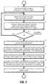
- FIG. 2is a flow chart of an interoperative guidance method according to an embodiment of the invention.
- FIG. 3illustrates a virtual stent superimposed on a 2D image display, according to an embodiment of the invention.
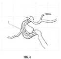
- FIG. 4illustrates a stent 41 superimposed on a DSA image of a lesion, according to an embodiment of the invention.
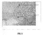
- FIG. 5illustrates exemplary stent end marker locations, according to an embodiment of the invention.
- FIG. 6is a block diagram of an exemplary computer system for implementing a method for intraoperative guidance of stent placement during endovascular interventions, according to an embodiment of the invention.
- Exemplary embodiments of the invention as described hereingenerally include systems and methods for intraoperative guidance of stent placement during endovascular interventions. Accordingly, while the invention is susceptible to various modifications and alternative forms, specific embodiments thereof are shown by way of example in the drawings and will herein be described in detail. It should be understood, however, that there is no intent to limit the invention to the particular forms disclosed, but on the contrary, the invention is to cover all modifications, equivalents, and alternatives falling within the spirit and scope of the invention.
- imagerefers to multi-dimensional data composed of discrete image elements (e.g., pixels for 2-D images and voxels for 3-D images).
- the imagemay be, for example, a medical image of a subject collected by computer tomography, magnetic resonance imaging, ultrasound, or any other medical imaging system known to one of skill in the art.
- the imagemay also be provided from non-medical contexts, such as, for example, remote sensing systems, electron microscopy, etc.
- an imagecan be thought of as a function from R 3 to R, the methods of the inventions are not limited to such images, and can be applied to images of any dimension, e.g., a 2-D picture or a 3-D volume.
- the domain of the imageis typically a 2- or 3-dimensional rectangular array, wherein each pixel or voxel can be addressed with reference to a set of 2 or 3 mutually orthogonal axes.
- digital and “digitized” as used hereinwill refer to images or volumes, as appropriate, in a digital or digitized format acquired via a digital acquisition system or via conversion from an analog image.
- FIGS. 1( a )-( c )An exemplary biplane angiography system is illustrated in FIGS. 1( a )-( c ).
- the angiography suiteincludes a control room that is isolated by leaded glass from the room with the C-arms and patient.
- the workstationsits in the control room.
- An exemplary workstationis a personal computer system.
- FIG. 1( a )shows the angiography room including a patient table 10 , two C-arms 11 and 12 and monitors 13 .
- FIG. 1( b )shows the setup of FIG. 1( a ) with a patient on the table and a physician.
- FIG. 1( c )is a view to the inside of the angiography from the control room, with the workstation's monitors in the foreground. Note that other embodiments of the invention can be used with monoplane systems as well as biplane systems.
- the output of an endovascular stent planning sessionis the required stent type, dimensions, shape and location in relationship to the lesion. Therefore at the end of a planning session it should be possible to fully create a virtual model of the stent by specifying its configuration in 3D space.
- an embodiment of the inventionallows the overlay of this 3D model of the virtual stent, or any part thereof, on any 2D image acquired by the fluoroscopy system, at any orientation, pan or zoom factor of the C-arm.
- the graphical overlay of the virtual stent model on a two dimensional imageprovides the physician with two functions. First, it allows the physician to check and revise the results of the stent planning through the overlay of the stent on 2D DSA images. This is useful since stent deployment is usually performed under guidance of a composite image formed of the superposition of a roadmap image derived from DSA and a fluoroscopy image. Second, an embodiment of the invention can superimpose the planned stent end positions on the fluoroscopic image where they can be directly compared to the position of radio-opaque markers at both ends of a real stent. This provides guidance to the physician who is then able to navigate the stent deployment mechanism until the planned position is reached with high accuracy.
- FIG. 2is a flow chart of an interoperative guidance method according to an embodiment of the invention.
- the steps involvedare as follows.
- a 3D DSA image of a patient's contrast-enhanced blood vesselsis constructed from 2D DSA images obtained via rotation of the X-ray C-arm around the patient.
- a physicianloads the 3D DSA image onto an angiography workstation and uses stent planning software to determine the length, diameter, type and location of the stent.
- Stent planning softwareis typically not provided by the stent vendors, but is rather a separate product that available for imaging systems from third party vendors.
- the output of the planning softwareis a virtual planned stent that can be saved in a computer file on the workstation.
- the virtual stentincludes virtual end markers that correspond to the actual stent markers.
- stent planningmay be performed on a 3D image from another imaging modality such as magnetic resonance imaging (MRI), or computed tomography (CT), not just a 3d dsa IMAGE.
- MRImagnetic resonance imaging
- CTcomputed tomography
- the imagesare typically acquired before the aneurysm/stenosis treatment procedure in the angiography suite.
- the 3D virtual stent modelis based on that other modality, but this model is registered with the 2D fluoroscopy images via one of a number of ways including 3D/3D registration involving 3D DSA as an intermediate step, or direct image-based 3D/2D registration.
- the physiciancan use an embodiment of the invention to overlay the outline and shape of the virtual planned stent on any 2D DSA image acquired for the lesion and saved on the angiography workstation. This allows the physician to examine the virtual planned stent in relationship to the lesion in C-arm projections at various orientations that are used during the placement of the stent. If, at step 24 , the location of the stent is unsatisfactory on the DSA images, the physician can return to step 22 and iteratively revise the location of stent using the stent planning software. At the end of step 23 , the planned location and configuration of the stent in three dimensions is fully specified.
- the physicianacquires a roadmap image using DSA to aid in navigating the actual stent to the target, and at step 26 manipulates the stent deployment mechanism to navigate the actual stent until it reaches the general area of the target lesion.
- the stentis identified by radio-opaque markers at both ends.
- the roadmap imagecan be the same as the DSA image that is used for planning, in other embodiments, the DSA roadmap image is created on the spot after planning is done and when the doctor is inside the interventional room and navigating the catheter or stent deployment system through a patient's vessels.
- the virtual stent markersare projected at step 27 onto the fluoroscopic image displayed on the live monitor inside the control room of the angiography suite.
- the physiciancan obtain this superimposition of the virtual stent markers on the live fluoroscopic images at any angle, pan, or zoom factor for the C-arm.
- the location of the virtual stent markersare automatically updated whenever the physician acquires a new image or moves the C-arm.
- the projective geometry of the C-armis described below.
- the shape and intensity of the projected stent and markersare also described below.
- the physicianmanipulates the stent deployment mechanism to align the real stent end markers with the virtual stent end markers projected on the fluoroscopic image.
- the physician at step 28deploys the stent according to the method described by the stent manufacturer.
- An invention according to an embodiment of the inventionmakes use of knowledge of the projective geometry of a fluoroscopic C-arm to superimpose stent planning information derived from 3D DSA images onto the two dimensional fluoroscopic images.
- ⁇a scalar
- Pa 3 ⁇ 4 matrix with 10 degrees of freedom.
- the parameters of Pmay be obtained through knowledge of the geometric design parameters of the C-arm, system calibration procedure, and the location of the C-arm.
- the matrix Pis a product of two matrices: 1 ⁇ T.
- the matrix Iis a 3 ⁇ 3 matrix that embodies the intrinsic parameters of the C-arm, which are determined via the calibration procedure and knowledge of the some system parameters, such as the relationship of the X-ray source to the detector.
- the matrix Tis a 3 ⁇ 4 matrix that is a coordinate transformation matrix that depends on the C-arm angles, of which there are two, and the translation of the C-arm with respect to a fixed coordinate system.
- the constant ⁇is determined as the 3rd coordinate on the left hand side of the equation. Knowing P and the (x, y, z) coordinates of a 3D point, everything on the left hand side can be determined.
- the coordinates u and vcan then be obtained by dividing the first and second components of the left hand side vector by ⁇ . In other words, after the left hand side is determined, divide the first component by the 3rd component to get u and divide the second component by the third to get v.
- the 3D DSA imagecan be registered to the 2D fluoroscopic image.
- 3D to 2D registration methodsThere are many 3D to 2D registration methods known in the art. A review of many such methods can be found in G. P. Penney, “Registration of Tomographic Images to X-ray Projections for Use in Image Guided Interventions,” Phd thesis, University College London, CISG, Division of Radiological Sciences, Guy's Hospital, King's College London, London SE1 9RT England, 2000, the contents of which are herein incorporated by reference in their entirety. Display of Planned Stent on 2D DSA Images
- FIG. 3illustrates a virtual stent superimposed on a 2D image display with centerline 31 and perpendicular lines 32 .
- centerline 31For the sake of clarity, only two such perpendicular lines are indicated by the reference number. The length of each line is equal to the diameter of expansion of the stent at that location.
- a 2D DSA imagecontains either high intensity pixels (background) or dark low intensity pixels (blood vessels filled with contrast). Since most angiography workstations allow the use of colors on display monitors, according to an embodiment of the invention, the stent is superimposed on the DSA image via a non grayscale color such as the color red.
- FIG. 4illustrates a stent 41 superimposed on a DSA image of a lesion.
- the display of the superimpositionneed not be restricted to a colored stent.
- a stentmay also be displayed in a bright white color, which will make it visible on the dark vessels.
- Navigation of a stent to its planned locationis performed under guidance of fluoroscopic images.
- the roadmap imageis typically superimposed on the fluoroscopy image to visualize the blood vessels and the target lesion.
- the planned stent end markers positionsare superimposed on the combined fluoroscopic and roadmap image display inside the angiography suite control room.
- the target marker end locationsare displayed in the shape of a cross hair surrounded by a circle.
- FIG. 5illustrates exemplary stent end marker locations 51 , 52 .
- the diameter of this circleis slightly larger than the size of the end marker of a real stent.
- the diameter of the circleshould be about 0.5 mm larger than the typical marker size for each stent on fluoroscopic images.
- the marker size information for each stent typeis kept in lookup table in a computer file.
- embodiments of the inventionare not limited to this end marker, and in other embodiments of the invention, the virtual end markers can be displayed in other shapes and forms.
- another embodiment of the inventionmay display 2 lines perpendicular to the center line and extending the whole width of the planned stent. These lines could be 1 mm before and 1 mm after the planned virtual stent end markers location. In that case, the goal of doctor would be to place the real stent markers in between these two lines.
- Some live monitors in the interventional suiteare capable of displaying colors and others can only display gray scale colors.
- the formerit is possible to superimpose the planned stent marker locations in a color such as the red color.
- embodiments of the present inventioncan be implemented in various forms of hardware, software, firmware, special purpose processes, or a combination thereof.
- the present inventioncan be implemented in software as an application program tangible embodied on a computer readable program storage device.
- the application programcan be uploaded to, and executed by, a machine comprising any suitable architecture.
- FIG. 6is a block diagram of an exemplary computer system for implementing a method for intraoperative guidance of stent placement during endovascular interventions, according to an embodiment of the invention.
- a computer system 61 for implementing the present inventioncan comprise, inter alia, a central processing unit (CPU) 62 , a memory 63 and an input/output (I/O) interface 64 .
- the computer system 61is generally coupled through the I/O interface 64 to a display 65 and various input devices 66 such as a mouse and a keyboard.
- the support circuitscan include circuits such as cache, power supplies, clock circuits, and a communication bus.
- the memory 63can include random access memory (RAM), read only memory (ROM), disk drive, tape drive, etc., or a combinations thereof.
- RAMrandom access memory
- ROMread only memory
- the present inventioncan be implemented as a routine 67 that is stored in memory 63 and executed by the CPU 62 to process the signal from the signal source 68 .
- the computer system 61is a general purpose computer system that becomes a specific purpose computer system when executing the routine 67 of the present invention.
- the computer system 61also includes an operating system and micro instruction code.
- the various processes and functions described hereincan either be part of the micro instruction code or part of the application program (or combination thereof) which is executed via the operating system.
- various other peripheral devicescan be connected to the computer platform such as an additional data storage device and a printing device.
Landscapes
- Health & Medical Sciences (AREA)
- Engineering & Computer Science (AREA)
- Life Sciences & Earth Sciences (AREA)
- Medical Informatics (AREA)
- Physics & Mathematics (AREA)
- Biomedical Technology (AREA)
- Surgery (AREA)
- Heart & Thoracic Surgery (AREA)
- Animal Behavior & Ethology (AREA)
- General Health & Medical Sciences (AREA)
- Public Health (AREA)
- Veterinary Medicine (AREA)
- Molecular Biology (AREA)
- Nuclear Medicine, Radiotherapy & Molecular Imaging (AREA)
- Optics & Photonics (AREA)
- Biophysics (AREA)
- High Energy & Nuclear Physics (AREA)
- Theoretical Computer Science (AREA)
- Pathology (AREA)
- Radiology & Medical Imaging (AREA)
- General Physics & Mathematics (AREA)
- Computer Vision & Pattern Recognition (AREA)
- Vascular Medicine (AREA)
- Oral & Maxillofacial Surgery (AREA)
- Robotics (AREA)
- Dentistry (AREA)
- Cardiology (AREA)
- Transplantation (AREA)
- Computer Graphics (AREA)
- Computer Hardware Design (AREA)
- General Engineering & Computer Science (AREA)
- Software Systems (AREA)
- Apparatus For Radiation Diagnosis (AREA)
Abstract
Description
where and P is a 3×4 matrix with 10 degrees of freedom obtained from knowledge of design parameters of the C-arm, system calibration procedure, and a location of the C-arm, (x, y, z) is a point in the 3D image, and α is a scalar determined by specifying P and (x, y, z).
where α is a scalar and P is a 3×4 matrix with 10 degrees of freedom. The parameters of P may be obtained through knowledge of the geometric design parameters of the C-arm, system calibration procedure, and the location of the C-arm. The matrix P is a product of two matrices: 1×T. The matrix I is a 3×3 matrix that embodies the intrinsic parameters of the C-arm, which are determined via the calibration procedure and knowledge of the some system parameters, such as the relationship of the X-ray source to the detector. The matrix T is a 3×4 matrix that is a coordinate transformation matrix that depends on the C-arm angles, of which there are two, and the translation of the C-arm with respect to a fixed coordinate system. The constant α is determined as the 3rd coordinate on the left hand side of the equation. Knowing P and the (x, y, z) coordinates of a 3D point, everything on the left hand side can be determined. The coordinates u and v can then be obtained by dividing the first and second components of the left hand side vector by α. In other words, after the left hand side is determined, divide the first component by the 3rd component to get u and divide the second component by the third to get v. Once the parameters of P are obtained, the 3D DSA image can be registered to the 2D fluoroscopic image. There are many 3D to 2D registration methods known in the art. A review of many such methods can be found in G. P. Penney, “Registration of Tomographic Images to X-ray Projections for Use in Image Guided Interventions,” Phd thesis, University College London, CISG, Division of Radiological Sciences, Guy's Hospital, King's College London, London SE1 9RT England, 2000, the contents of which are herein incorporated by reference in their entirety.
Display of Planned Stent on 2D DSA Images
Io=Imax+Imin−Ii,
where Imaxand Iminare the minimum and maximum intensity values of the display monitor, respectively.
System Implementation
Claims (24)
Priority Applications (1)
| Application Number | Priority Date | Filing Date | Title |
|---|---|---|---|
| US12/031,787US8060186B2 (en) | 2007-02-15 | 2008-02-15 | System and method for intraoperative guidance of stent placement during endovascular interventions |
Applications Claiming Priority (2)
| Application Number | Priority Date | Filing Date | Title |
|---|---|---|---|
| US89003607P | 2007-02-15 | 2007-02-15 | |
| US12/031,787US8060186B2 (en) | 2007-02-15 | 2008-02-15 | System and method for intraoperative guidance of stent placement during endovascular interventions |
Publications (2)
| Publication Number | Publication Date |
|---|---|
| US20090088830A1 US20090088830A1 (en) | 2009-04-02 |
| US8060186B2true US8060186B2 (en) | 2011-11-15 |
Family
ID=40509262
Family Applications (1)
| Application Number | Title | Priority Date | Filing Date |
|---|---|---|---|
| US12/031,787Active2030-06-13US8060186B2 (en) | 2007-02-15 | 2008-02-15 | System and method for intraoperative guidance of stent placement during endovascular interventions |
Country Status (1)
| Country | Link |
|---|---|
| US (1) | US8060186B2 (en) |
Cited By (4)
| Publication number | Priority date | Publication date | Assignee | Title |
|---|---|---|---|---|
| US20110268333A1 (en)* | 2010-04-30 | 2011-11-03 | Klaus Klingenbeck | Imaging method for enhanced visualization of vessels in an examination region of a patient and medical system for performing the method |
| US20130308844A1 (en)* | 2011-02-07 | 2013-11-21 | Koninklijke Philips N.V. | Medical imaging device for providing an image representation supporting the accurate positioning of an invention device in vessel intervention procedures |
| US20160217375A1 (en)* | 2015-01-28 | 2016-07-28 | Infinitt Healthcare Co., Ltd. | Method and system for stent recommendation |
| US10499997B2 (en) | 2017-01-03 | 2019-12-10 | Mako Surgical Corp. | Systems and methods for surgical navigation |
Families Citing this family (66)
| Publication number | Priority date | Publication date | Assignee | Title |
|---|---|---|---|---|
| US7689014B2 (en)* | 2000-01-18 | 2010-03-30 | Z-Kat Inc | Apparatus and method for measuring anatomical objects using coordinated fluoroscopy |
| US20080262390A1 (en)* | 2007-04-19 | 2008-10-23 | Searete Llc, A Limited Liability Corporation Of The State Of Delaware | Fiducials for placement of tissue closures |
| US20080262524A1 (en)* | 2007-04-19 | 2008-10-23 | Searete Llc, A Limited Liability Corporation Of The State Of Delaware | Systems and methods for closing of fascia |
| US20080275467A1 (en)* | 2007-05-02 | 2008-11-06 | Siemens Corporate Research, Inc. | Intraoperative guidance for endovascular interventions via three-dimensional path planning, x-ray fluoroscopy, and image overlay |
| US8041095B2 (en)* | 2008-06-11 | 2011-10-18 | Siemens Aktiengesellschaft | Method and apparatus for pretreatment planning of endovascular coil placement |
| US8200466B2 (en) | 2008-07-21 | 2012-06-12 | The Board Of Trustees Of The Leland Stanford Junior University | Method for tuning patient-specific cardiovascular simulations |
| US9402590B2 (en)* | 2008-10-15 | 2016-08-02 | Toshiba Medical Systems Corporation | Three-dimensional image processing apparatus and X-ray diagnostic apparatus |
| US20120172711A1 (en)* | 2009-02-04 | 2012-07-05 | Marshall Kerr | Injectable Vascular Access Port with Discernable Markers for Identification |
| US9405886B2 (en) | 2009-03-17 | 2016-08-02 | The Board Of Trustees Of The Leland Stanford Junior University | Method for determining cardiovascular information |
| CA2761652C (en) | 2009-05-11 | 2019-10-01 | Leigh E. Colby | Therapeutic tooth bud ablation |
| US10022202B2 (en) | 2013-03-15 | 2018-07-17 | Triagenics, Llc | Therapeutic tooth bud ablation |
| WO2014143014A1 (en) | 2013-03-15 | 2014-09-18 | Triagenics, Llc | Therapeutic tooth bud ablation |
| US8654119B2 (en)* | 2009-08-17 | 2014-02-18 | Mistretta Medical, Llc | System and method for four dimensional angiography and fluoroscopy |
| US8643642B2 (en)* | 2009-08-17 | 2014-02-04 | Mistretta Medical, Llc | System and method of time-resolved, three-dimensional angiography |
| US12426789B2 (en) | 2009-09-23 | 2025-09-30 | Lightlab Imaging, Inc. | Blood vessel lumen morphology and minimum lumen area measurements data collection by intravascular imaging systems for stenosis or stent planning |
| CN102665569B (en) | 2009-10-12 | 2015-05-13 | 硅谷医疗器械有限公司 | Intravascular ultrasound system for co-registered imaging |
| JP5702572B2 (en)* | 2009-10-29 | 2015-04-15 | 株式会社東芝 | X-ray equipment |
| WO2011091300A2 (en) | 2010-01-24 | 2011-07-28 | Mistretta Medical, Llc | System and method for implementation of 4d time-energy subtraction computed tomography |
| FR2959584B1 (en) | 2010-04-29 | 2012-07-27 | Gen Electric | METHOD FOR PROCESSING RADIOLOGICAL IMAGES |
| US8315812B2 (en) | 2010-08-12 | 2012-11-20 | Heartflow, Inc. | Method and system for patient-specific modeling of blood flow |
| US8768031B2 (en) | 2010-10-01 | 2014-07-01 | Mistretta Medical, Llc | Time resolved digital subtraction angiography perfusion measurement method, apparatus and system |
| WO2012097315A1 (en)* | 2011-01-14 | 2012-07-19 | Baylor College Of Medicine | Method and system for evaluating hemodynamics of a blood vessel |
| CN103619237B (en) | 2011-06-15 | 2016-03-16 | 米斯特雷塔医疗有限公司 | For 4D angio radiography and fluoroscopic system and method |
| DE102011083063B4 (en)* | 2011-09-20 | 2022-09-01 | Siemens Healthcare Gmbh | Method for generating planning data for an implant |
| US8983809B2 (en) | 2011-12-06 | 2015-03-17 | Siemens Aktiengesellschaft | Method and system for patient-specific hemodynamic assessment of virtual stent implantation |
| US8989843B2 (en) | 2012-06-05 | 2015-03-24 | DePuy Synthes Products, LLC | Methods and apparatus for estimating the position and orientation of an implant using a mobile device |
| EP2943123B1 (en)* | 2013-01-08 | 2023-12-13 | Biocardia, Inc. | Target site selection, entry and update with automatic remote image annotation |
| US9438264B1 (en) | 2015-09-10 | 2016-09-06 | Realtek Semiconductor Corp. | High-speed capacitive digital-to-analog converter and method thereof |
| JP6138566B2 (en)* | 2013-04-24 | 2017-05-31 | 川崎重工業株式会社 | Component mounting work support system and component mounting method |
| US9693754B2 (en) | 2013-05-15 | 2017-07-04 | Acist Medical Systems, Inc. | Imaging processing systems and methods |
| DE102013219737B4 (en) | 2013-09-30 | 2019-05-09 | Siemens Healthcare Gmbh | Angiographic examination procedure of a vascular system |
| JP6353038B2 (en) | 2013-10-07 | 2018-07-04 | アシスト・メディカル・システムズ,インコーポレイテッド | Signal processing for intravascular imaging |
| US10019800B2 (en)* | 2014-01-06 | 2018-07-10 | Koninklijke Philips N.V. | Deployment modelling |
| US9747525B2 (en)* | 2014-06-16 | 2017-08-29 | Siemens Healthcare Gmbh | Method and system for improved hemodynamic computation in coronary arteries |
| US9888968B2 (en)* | 2014-07-22 | 2018-02-13 | Siemens Healthcare Gmbh | Method and system for automated therapy planning for arterial stenosis |
| GB2534359A (en)* | 2015-01-15 | 2016-07-27 | Corin Ltd | System and method for patient implant alignment |
| KR101703564B1 (en)* | 2015-01-28 | 2017-02-08 | 주식회사 인피니트헬스케어 | Appratus and method for displaying medical images including information of vascular structure |
| EP3157435B1 (en) | 2015-05-20 | 2018-01-31 | Koninklijke Philips N.V. | Guiding system for positioning a patient for medical imaging |
| FR3037785B1 (en)* | 2015-06-26 | 2017-08-18 | Therenva | METHOD AND SYSTEM FOR GUIDING A ENDOVASCULAR TOOL IN VASCULAR STRUCTURES |
| US10909661B2 (en) | 2015-10-08 | 2021-02-02 | Acist Medical Systems, Inc. | Systems and methods to reduce near-field artifacts |
| US10653393B2 (en) | 2015-10-08 | 2020-05-19 | Acist Medical Systems, Inc. | Intravascular ultrasound imaging with frequency selective imaging methods and systems |
| US11369337B2 (en) | 2015-12-11 | 2022-06-28 | Acist Medical Systems, Inc. | Detection of disturbed blood flow |
| WO2017117389A1 (en) | 2015-12-31 | 2017-07-06 | Acist Medical Systems, Inc. | Semi-automated image segmentation system and method |
| IL245339A (en) | 2016-04-21 | 2017-10-31 | Rani Ben Yishai | Method and system for registration verification |
| US10489919B2 (en) | 2016-05-16 | 2019-11-26 | Acist Medical Systems, Inc. | Motion-based image segmentation systems and methods |
| US10806516B2 (en)* | 2016-06-20 | 2020-10-20 | General Electric Company | Virtual 4D stent implantation path assessment |
| US11839433B2 (en)* | 2016-09-22 | 2023-12-12 | Medtronic Navigation, Inc. | System for guided procedures |
| FI128589B (en)* | 2016-12-30 | 2020-08-31 | Planmeca Oy | Computed tomography and positioning of anatomy that you wish to have imaged |
| EP3406195A1 (en) | 2017-05-24 | 2018-11-28 | Koninklijke Philips N.V. | Device and a corresponding method for providing spatial information of an interventional device in a live 2d x-ray image |
| JP6840254B2 (en)* | 2017-09-27 | 2021-03-10 | 富士フイルム株式会社 | Virtual stenting equipment, methods and programs |
| JP6713092B2 (en)* | 2017-09-27 | 2020-06-24 | 富士フイルム株式会社 | Virtual stent placement device, method and program |
| US20190175059A1 (en) | 2017-12-07 | 2019-06-13 | Medtronic Xomed, Inc. | System and Method for Assisting Visualization During a Procedure |
| CN109931923B (en)* | 2017-12-15 | 2023-07-07 | 阿里巴巴集团控股有限公司 | Navigation guidance diagram generation method and device |
| WO2020123671A1 (en)* | 2018-12-11 | 2020-06-18 | Project Moray, Inc. | Hybrid-dimensional, augmented reality, and/or registration of user interface and simulation systems for robotic catheters and other uses |
| CN109934913A (en)* | 2019-03-19 | 2019-06-25 | 肖仁德 | The virtual intervention support method for implantation of intracranial aneurysm, device, computer equipment |
| EP4413935A3 (en) | 2019-06-06 | 2024-09-18 | TriAgenics, Inc. | Ablation probe systems |
| US11024034B2 (en) | 2019-07-02 | 2021-06-01 | Acist Medical Systems, Inc. | Image segmentation confidence determination |
| CN110693609B (en)* | 2019-08-30 | 2020-07-10 | 上海杏脉信息科技有限公司 | Implant intervention simulation method, selection method, medium and device |
| US11167127B2 (en) | 2020-01-24 | 2021-11-09 | Medtronic Xomed, Inc. | System and method for therapy |
| US11623086B2 (en) | 2020-01-24 | 2023-04-11 | Medtronic Xomed, Inc. | System and method for therapy |
| US11167140B2 (en) | 2020-01-24 | 2021-11-09 | Medtronic Xomed, Inc. | System and method for therapy |
| US11666755B2 (en) | 2020-01-24 | 2023-06-06 | Medtronic Xomed, Inc. | System and method for therapy |
| CN113679402B (en)* | 2020-05-18 | 2024-05-24 | 西门子(深圳)磁共振有限公司 | Image presentation method and system in interventional therapy, imaging system and storage medium |
| EP4316398B1 (en)* | 2022-08-04 | 2024-07-24 | Angiolutions GmbH | Method for defining a placement position of a stent |
| US12285283B2 (en)* | 2022-09-20 | 2025-04-29 | Shanghai United Imaging Intelligence Co., Ltd. | Systems and methods for medical image fusion |
| EP4523620A1 (en)* | 2023-09-15 | 2025-03-19 | Siemens Healthineers AG | Determining a length of a stent |
Citations (2)
| Publication number | Priority date | Publication date | Assignee | Title |
|---|---|---|---|---|
| US6733489B2 (en)* | 2002-09-26 | 2004-05-11 | Angiodynamics, Inc. | Vascular orientation marker for determining the orientation of a blood vessel |
| US20060184066A1 (en) | 2005-02-15 | 2006-08-17 | Baylor College Of Medicine | Method for aiding stent-assisted coiling of intracranial aneurysms by virtual parent artery reconstruction |
- 2008
- 2008-02-15USUS12/031,787patent/US8060186B2/enactiveActive
Patent Citations (2)
| Publication number | Priority date | Publication date | Assignee | Title |
|---|---|---|---|---|
| US6733489B2 (en)* | 2002-09-26 | 2004-05-11 | Angiodynamics, Inc. | Vascular orientation marker for determining the orientation of a blood vessel |
| US20060184066A1 (en) | 2005-02-15 | 2006-08-17 | Baylor College Of Medicine | Method for aiding stent-assisted coiling of intracranial aneurysms by virtual parent artery reconstruction |
Non-Patent Citations (1)
| Title |
|---|
| Penney, G., "Registration of Tomographic Images to X-ray Projections for Use in Image Guided Interventions", Computational Imaging Science Group, Division of Radiological Sciences and Medical Engineering, Guy's, King's and St. Thomas' School of Medicine, King's College London, Dec. 1999. |
Cited By (8)
| Publication number | Priority date | Publication date | Assignee | Title |
|---|---|---|---|---|
| US20110268333A1 (en)* | 2010-04-30 | 2011-11-03 | Klaus Klingenbeck | Imaging method for enhanced visualization of vessels in an examination region of a patient and medical system for performing the method |
| US8693758B2 (en)* | 2010-04-30 | 2014-04-08 | Siemens Aktiengesellschaft | Imaging method for enhanced visualization of vessels in an examination region of a patient and medical system for performing the method |
| US20130308844A1 (en)* | 2011-02-07 | 2013-11-21 | Koninklijke Philips N.V. | Medical imaging device for providing an image representation supporting the accurate positioning of an invention device in vessel intervention procedures |
| US9295435B2 (en)* | 2011-02-07 | 2016-03-29 | Koninklijke Philips N.V. | Image representation supporting the accurate positioning of an intervention device in vessel intervention procedures |
| US20160217375A1 (en)* | 2015-01-28 | 2016-07-28 | Infinitt Healthcare Co., Ltd. | Method and system for stent recommendation |
| US10499997B2 (en) | 2017-01-03 | 2019-12-10 | Mako Surgical Corp. | Systems and methods for surgical navigation |
| US11707330B2 (en) | 2017-01-03 | 2023-07-25 | Mako Surgical Corp. | Systems and methods for surgical navigation |
| US12383347B2 (en) | 2017-01-03 | 2025-08-12 | Mako Surgical Corp. | Systems and methods for surgical navigation |
Also Published As
| Publication number | Publication date |
|---|---|
| US20090088830A1 (en) | 2009-04-02 |
Similar Documents
| Publication | Publication Date | Title |
|---|---|---|
| US8060186B2 (en) | System and method for intraoperative guidance of stent placement during endovascular interventions | |
| EP2188782B1 (en) | Coupling the viewing direction of a blood vessel's cpr view with the viewing angle on this 3d tubular structure's rendered voxel volume and/or with the c-arm geometry of a 3d rotational angiography device's c-arm system | |
| US20080275467A1 (en) | Intraoperative guidance for endovascular interventions via three-dimensional path planning, x-ray fluoroscopy, and image overlay | |
| US10650513B2 (en) | Method and system for tomosynthesis imaging | |
| US11013481B2 (en) | Method for acquiring and processing image data of an examination object | |
| EP2349004B1 (en) | Angiographic image acquisition system and method with automatic shutter adaptation for yielding a reduced field of view covering a segmented target structure or lesion for decreasing x-radiation dose in minimally invasive x-ray-guided interventions | |
| EP3258851B1 (en) | Digital image remapping | |
| US7302286B2 (en) | Method and apparatus for the three-dimensional presentation of an examination region of a patient in the form of a 3D reconstruction image | |
| US20080147086A1 (en) | Integrating 3D images into interventional procedures | |
| Jones et al. | Image fusion and 3-dimensional roadmapping in endovascular surgery | |
| JP5030588B2 (en) | Apparatus and method for combining two images | |
| US6317621B1 (en) | Method and device for catheter navigation in three-dimensional vascular tree exposures | |
| US9042628B2 (en) | 3D-originated cardiac roadmapping | |
| EP2049021B1 (en) | Automatic iso-centering for rotational angiography | |
| CN110891513A (en) | Method and system for assisting in guiding an intravascular device | |
| JP2004243117A (en) | Method for obtaining physical parameters of physiological structure | |
| JP2009022754A (en) | Method for correcting registration of radiography images | |
| JP2012505009A5 (en) | ||
| JP2013517012A (en) | Intervention device navigation | |
| JP5641707B2 (en) | X-ray diagnostic equipment | |
| KR101703564B1 (en) | Appratus and method for displaying medical images including information of vascular structure | |
| Abi-Jaoudeh et al. | Electromagnetic navigation for thoracic aortic stent-graft deployment: a pilot study in swine | |
| JP5100041B2 (en) | Image processing apparatus and image processing program | |
| Breininger et al. | Simultaneous reconstruction of multiple stiff wires from a single X-ray projection for endovascular aortic repair | |
| Gorges et al. | 3D augmented fluoroscopy in interventional neuroradiology: precision assessment and first evaluation on clinical cases |
Legal Events
| Date | Code | Title | Description |
|---|---|---|---|
| AS | Assignment | Owner name:SIEMENS CORPORATE RESEARCH, INC., NEW JERSEY Free format text:ASSIGNMENT OF ASSIGNORS INTEREST;ASSIGNORS:MOHAMED, ASHRAF;SAUER, FRANK;XU, CHENYANG;REEL/FRAME:021787/0802;SIGNING DATES FROM 20080306 TO 20080403 Owner name:SIEMENS AKTIENGESELLSCHAFT, GERMANY Free format text:ASSIGNMENT OF ASSIGNORS INTEREST;ASSIGNORS:KLINGENBECK-REGN, KLAUS;PFISTER, MARCUS;REEL/FRAME:021787/0868;SIGNING DATES FROM 20080422 TO 20080424 Owner name:SIEMENS MEDICAL SOLUTIONS USA, INC., PENNSYLVANIA Free format text:ASSIGNMENT OF ASSIGNORS INTEREST;ASSIGNOR:HALL, ANDREW;REEL/FRAME:021787/0983 Effective date:20080423 Owner name:SIEMENS CORPORATE RESEARCH, INC., NEW JERSEY Free format text:ASSIGNMENT OF ASSIGNORS INTEREST;ASSIGNORS:MOHAMED, ASHRAF;SAUER, FRANK;XU, CHENYANG;SIGNING DATES FROM 20080306 TO 20080403;REEL/FRAME:021787/0802 Owner name:SIEMENS AKTIENGESELLSCHAFT, GERMANY Free format text:ASSIGNMENT OF ASSIGNORS INTEREST;ASSIGNORS:KLINGENBECK-REGN, KLAUS;PFISTER, MARCUS;SIGNING DATES FROM 20080422 TO 20080424;REEL/FRAME:021787/0868 | |
| AS | Assignment | Owner name:SIEMENS AKTIENGESELLSCHAFT, GERMANY Free format text:ASSIGNMENT OF ASSIGNORS INTEREST;ASSIGNOR:SIEMENS CORPORATE RESEARCH, INC.;REEL/FRAME:022506/0596 Effective date:20090403 Owner name:SIEMENS AKTIENGESELLSCHAFT,GERMANY Free format text:ASSIGNMENT OF ASSIGNORS INTEREST;ASSIGNOR:SIEMENS CORPORATE RESEARCH, INC.;REEL/FRAME:022506/0596 Effective date:20090403 | |
| STCF | Information on status: patent grant | Free format text:PATENTED CASE | |
| FPAY | Fee payment | Year of fee payment:4 | |
| AS | Assignment | Owner name:SIEMENS HEALTHCARE GMBH, GERMANY Free format text:ASSIGNMENT OF ASSIGNORS INTEREST;ASSIGNOR:SIEMENS AKTIENGESELLSCHAFT;REEL/FRAME:039011/0411 Effective date:20160610 | |
| MAFP | Maintenance fee payment | Free format text:PAYMENT OF MAINTENANCE FEE, 8TH YEAR, LARGE ENTITY (ORIGINAL EVENT CODE: M1552); ENTITY STATUS OF PATENT OWNER: LARGE ENTITY Year of fee payment:8 | |
| MAFP | Maintenance fee payment | Free format text:PAYMENT OF MAINTENANCE FEE, 12TH YEAR, LARGE ENTITY (ORIGINAL EVENT CODE: M1553); ENTITY STATUS OF PATENT OWNER: LARGE ENTITY Year of fee payment:12 | |
| AS | Assignment | Owner name:SIEMENS HEALTHINEERS AG, GERMANY Free format text:ASSIGNMENT OF ASSIGNORS INTEREST;ASSIGNOR:SIEMENS HEALTHCARE GMBH;REEL/FRAME:066088/0256 Effective date:20231219 | |
| AS | Assignment | Owner name:SIEMENS HEALTHINEERS AG, GERMANY Free format text:CORRECTIVE ASSIGNMENT TO CORRECT THE ASSIGNEE PREVIOUSLY RECORDED AT REEL: 066088 FRAME: 0256. ASSIGNOR(S) HEREBY CONFIRMS THE ASSIGNMENT;ASSIGNOR:SIEMENS HEALTHCARE GMBH;REEL/FRAME:071178/0246 Effective date:20231219 |