US8059073B2 - Organic light emitting diode display and driving method thereof - Google Patents
Organic light emitting diode display and driving method thereofDownload PDFInfo
- Publication number
- US8059073B2 US8059073B2US12/007,452US745208AUS8059073B2US 8059073 B2US8059073 B2US 8059073B2US 745208 AUS745208 AUS 745208AUS 8059073 B2US8059073 B2US 8059073B2
- Authority
- US
- United States
- Prior art keywords
- data
- input image
- image data
- saturation
- changed
- Prior art date
- Legal status (The legal status is an assumption and is not a legal conclusion. Google has not performed a legal analysis and makes no representation as to the accuracy of the status listed.)
- Active, expires
Links
Images


Classifications
- G—PHYSICS
- G09—EDUCATION; CRYPTOGRAPHY; DISPLAY; ADVERTISING; SEALS
- G09G—ARRANGEMENTS OR CIRCUITS FOR CONTROL OF INDICATING DEVICES USING STATIC MEANS TO PRESENT VARIABLE INFORMATION
- G09G3/00—Control arrangements or circuits, of interest only in connection with visual indicators other than cathode-ray tubes
- G09G3/20—Control arrangements or circuits, of interest only in connection with visual indicators other than cathode-ray tubes for presentation of an assembly of a number of characters, e.g. a page, by composing the assembly by combination of individual elements arranged in a matrix no fixed position being assigned to or needed to be assigned to the individual characters or partial characters
- G09G3/22—Control arrangements or circuits, of interest only in connection with visual indicators other than cathode-ray tubes for presentation of an assembly of a number of characters, e.g. a page, by composing the assembly by combination of individual elements arranged in a matrix no fixed position being assigned to or needed to be assigned to the individual characters or partial characters using controlled light sources
- G09G3/30—Control arrangements or circuits, of interest only in connection with visual indicators other than cathode-ray tubes for presentation of an assembly of a number of characters, e.g. a page, by composing the assembly by combination of individual elements arranged in a matrix no fixed position being assigned to or needed to be assigned to the individual characters or partial characters using controlled light sources using electroluminescent panels
- G—PHYSICS
- G09—EDUCATION; CRYPTOGRAPHY; DISPLAY; ADVERTISING; SEALS
- G09G—ARRANGEMENTS OR CIRCUITS FOR CONTROL OF INDICATING DEVICES USING STATIC MEANS TO PRESENT VARIABLE INFORMATION
- G09G3/00—Control arrangements or circuits, of interest only in connection with visual indicators other than cathode-ray tubes
- G09G3/20—Control arrangements or circuits, of interest only in connection with visual indicators other than cathode-ray tubes for presentation of an assembly of a number of characters, e.g. a page, by composing the assembly by combination of individual elements arranged in a matrix no fixed position being assigned to or needed to be assigned to the individual characters or partial characters
- G09G3/2003—Display of colours
- G—PHYSICS
- G01—MEASURING; TESTING
- G01J—MEASUREMENT OF INTENSITY, VELOCITY, SPECTRAL CONTENT, POLARISATION, PHASE OR PULSE CHARACTERISTICS OF INFRARED, VISIBLE OR ULTRAVIOLET LIGHT; COLORIMETRY; RADIATION PYROMETRY
- G01J1/00—Photometry, e.g. photographic exposure meter
- G01J1/38—Photometry, e.g. photographic exposure meter using wholly visual means
- G01J1/40—Photometry, e.g. photographic exposure meter using wholly visual means using limit or visibility or extinction effect
- G—PHYSICS
- G09—EDUCATION; CRYPTOGRAPHY; DISPLAY; ADVERTISING; SEALS
- G09G—ARRANGEMENTS OR CIRCUITS FOR CONTROL OF INDICATING DEVICES USING STATIC MEANS TO PRESENT VARIABLE INFORMATION
- G09G3/00—Control arrangements or circuits, of interest only in connection with visual indicators other than cathode-ray tubes
- G09G3/20—Control arrangements or circuits, of interest only in connection with visual indicators other than cathode-ray tubes for presentation of an assembly of a number of characters, e.g. a page, by composing the assembly by combination of individual elements arranged in a matrix no fixed position being assigned to or needed to be assigned to the individual characters or partial characters
- G09G3/22—Control arrangements or circuits, of interest only in connection with visual indicators other than cathode-ray tubes for presentation of an assembly of a number of characters, e.g. a page, by composing the assembly by combination of individual elements arranged in a matrix no fixed position being assigned to or needed to be assigned to the individual characters or partial characters using controlled light sources
- G09G3/30—Control arrangements or circuits, of interest only in connection with visual indicators other than cathode-ray tubes for presentation of an assembly of a number of characters, e.g. a page, by composing the assembly by combination of individual elements arranged in a matrix no fixed position being assigned to or needed to be assigned to the individual characters or partial characters using controlled light sources using electroluminescent panels
- G09G3/32—Control arrangements or circuits, of interest only in connection with visual indicators other than cathode-ray tubes for presentation of an assembly of a number of characters, e.g. a page, by composing the assembly by combination of individual elements arranged in a matrix no fixed position being assigned to or needed to be assigned to the individual characters or partial characters using controlled light sources using electroluminescent panels semiconductive, e.g. using light-emitting diodes [LED]
- G—PHYSICS
- G09—EDUCATION; CRYPTOGRAPHY; DISPLAY; ADVERTISING; SEALS
- G09G—ARRANGEMENTS OR CIRCUITS FOR CONTROL OF INDICATING DEVICES USING STATIC MEANS TO PRESENT VARIABLE INFORMATION
- G09G2300/00—Aspects of the constitution of display devices
- G09G2300/08—Active matrix structure, i.e. with use of active elements, inclusive of non-linear two terminal elements, in the pixels together with light emitting or modulating elements
- G09G2300/0809—Several active elements per pixel in active matrix panels
- G09G2300/0842—Several active elements per pixel in active matrix panels forming a memory circuit, e.g. a dynamic memory with one capacitor
- G09G2300/0861—Several active elements per pixel in active matrix panels forming a memory circuit, e.g. a dynamic memory with one capacitor with additional control of the display period without amending the charge stored in a pixel memory, e.g. by means of additional select electrodes
- G—PHYSICS
- G09—EDUCATION; CRYPTOGRAPHY; DISPLAY; ADVERTISING; SEALS
- G09G—ARRANGEMENTS OR CIRCUITS FOR CONTROL OF INDICATING DEVICES USING STATIC MEANS TO PRESENT VARIABLE INFORMATION
- G09G2320/00—Control of display operating conditions
- G09G2320/02—Improving the quality of display appearance
- G09G2320/0242—Compensation of deficiencies in the appearance of colours
- G—PHYSICS
- G09—EDUCATION; CRYPTOGRAPHY; DISPLAY; ADVERTISING; SEALS
- G09G—ARRANGEMENTS OR CIRCUITS FOR CONTROL OF INDICATING DEVICES USING STATIC MEANS TO PRESENT VARIABLE INFORMATION
- G09G2320/00—Control of display operating conditions
- G09G2320/06—Adjustment of display parameters
- G09G2320/0626—Adjustment of display parameters for control of overall brightness
- G—PHYSICS
- G09—EDUCATION; CRYPTOGRAPHY; DISPLAY; ADVERTISING; SEALS
- G09G—ARRANGEMENTS OR CIRCUITS FOR CONTROL OF INDICATING DEVICES USING STATIC MEANS TO PRESENT VARIABLE INFORMATION
- G09G2320/00—Control of display operating conditions
- G09G2320/06—Adjustment of display parameters
- G09G2320/0666—Adjustment of display parameters for control of colour parameters, e.g. colour temperature
- G—PHYSICS
- G09—EDUCATION; CRYPTOGRAPHY; DISPLAY; ADVERTISING; SEALS
- G09G—ARRANGEMENTS OR CIRCUITS FOR CONTROL OF INDICATING DEVICES USING STATIC MEANS TO PRESENT VARIABLE INFORMATION
- G09G2360/00—Aspects of the architecture of display systems
- G09G2360/14—Detecting light within display terminals, e.g. using a single or a plurality of photosensors
- G09G2360/144—Detecting light within display terminals, e.g. using a single or a plurality of photosensors the light being ambient light
- G—PHYSICS
- G09—EDUCATION; CRYPTOGRAPHY; DISPLAY; ADVERTISING; SEALS
- G09G—ARRANGEMENTS OR CIRCUITS FOR CONTROL OF INDICATING DEVICES USING STATIC MEANS TO PRESENT VARIABLE INFORMATION
- G09G2360/00—Aspects of the architecture of display systems
- G09G2360/18—Use of a frame buffer in a display terminal, inclusive of the display panel
- G—PHYSICS
- G09—EDUCATION; CRYPTOGRAPHY; DISPLAY; ADVERTISING; SEALS
- G09G—ARRANGEMENTS OR CIRCUITS FOR CONTROL OF INDICATING DEVICES USING STATIC MEANS TO PRESENT VARIABLE INFORMATION
- G09G3/00—Control arrangements or circuits, of interest only in connection with visual indicators other than cathode-ray tubes
- G09G3/20—Control arrangements or circuits, of interest only in connection with visual indicators other than cathode-ray tubes for presentation of an assembly of a number of characters, e.g. a page, by composing the assembly by combination of individual elements arranged in a matrix no fixed position being assigned to or needed to be assigned to the individual characters or partial characters
- G09G3/22—Control arrangements or circuits, of interest only in connection with visual indicators other than cathode-ray tubes for presentation of an assembly of a number of characters, e.g. a page, by composing the assembly by combination of individual elements arranged in a matrix no fixed position being assigned to or needed to be assigned to the individual characters or partial characters using controlled light sources
- G09G3/30—Control arrangements or circuits, of interest only in connection with visual indicators other than cathode-ray tubes for presentation of an assembly of a number of characters, e.g. a page, by composing the assembly by combination of individual elements arranged in a matrix no fixed position being assigned to or needed to be assigned to the individual characters or partial characters using controlled light sources using electroluminescent panels
- G09G3/32—Control arrangements or circuits, of interest only in connection with visual indicators other than cathode-ray tubes for presentation of an assembly of a number of characters, e.g. a page, by composing the assembly by combination of individual elements arranged in a matrix no fixed position being assigned to or needed to be assigned to the individual characters or partial characters using controlled light sources using electroluminescent panels semiconductive, e.g. using light-emitting diodes [LED]
- G09G3/3208—Control arrangements or circuits, of interest only in connection with visual indicators other than cathode-ray tubes for presentation of an assembly of a number of characters, e.g. a page, by composing the assembly by combination of individual elements arranged in a matrix no fixed position being assigned to or needed to be assigned to the individual characters or partial characters using controlled light sources using electroluminescent panels semiconductive, e.g. using light-emitting diodes [LED] organic, e.g. using organic light-emitting diodes [OLED]
- G09G3/3225—Control arrangements or circuits, of interest only in connection with visual indicators other than cathode-ray tubes for presentation of an assembly of a number of characters, e.g. a page, by composing the assembly by combination of individual elements arranged in a matrix no fixed position being assigned to or needed to be assigned to the individual characters or partial characters using controlled light sources using electroluminescent panels semiconductive, e.g. using light-emitting diodes [LED] organic, e.g. using organic light-emitting diodes [OLED] using an active matrix
- G—PHYSICS
- G09—EDUCATION; CRYPTOGRAPHY; DISPLAY; ADVERTISING; SEALS
- G09G—ARRANGEMENTS OR CIRCUITS FOR CONTROL OF INDICATING DEVICES USING STATIC MEANS TO PRESENT VARIABLE INFORMATION
- G09G5/00—Control arrangements or circuits for visual indicators common to cathode-ray tube indicators and other visual indicators
- G09G5/02—Control arrangements or circuits for visual indicators common to cathode-ray tube indicators and other visual indicators characterised by the way in which colour is displayed
- G09G5/06—Control arrangements or circuits for visual indicators common to cathode-ray tube indicators and other visual indicators characterised by the way in which colour is displayed using colour palettes, e.g. look-up tables
Definitions
- Example embodimentsrelate to an organic light emitting diode (OLED) display and a driving method thereof. More particularly, example embodiments relate to an OLED display having improved display and visibility across varying ambient light conditions and driving methods thereof.
- OLEDorganic light emitting diode
- OLED displaysmay have advantages over cathode ray tubes (CRT), e.g., reduced weight and volume.
- PDPsplasma display panels
- LCDsliquid crystal displays
- OLED displaysmay provide better luminance feature and color purity, as OLED displays use an organic compound as an emitting material.
- OLED displaysmay be thin and light, and may be driven with low power and, thus, applicable to portable display devices.
- portable display devicesmay be exposed to varying environments and light conditions, e.g., exposed to outdoor visible light, display quality and viewability or visibility of an image displayed on the portable display device may be reduced.
- the brightness of an image displayed on the portable display devicemay be reduced (or faded out) under light, e.g., solar light, in which surrounding or ambient light illumination intensity may be brighter than the brightness of the image displayed.
- a portable display devicee.g., an OLED display
- OLED displayhaving improved display and viewability across varying ambient light conditions and methods of driving such devices.
- Example embodimentsare therefore related to an OLED display, and methods for driving the same, which substantially overcome one or more of the problems due to the limitations and disadvantages of the related art.
- At least one of the above and other features of example embodimentsmay provide an OLED display, including a pixel portion having a plurality of pixels connected to scan lines and data lines, a scan driver adapted to generate and supply scan signals to the scan lines, a data driver adapted to generate and supply data signals to the data lines, an optical sensor adapted to generate an optical sensing signal according to an intensity of light, and a data converter adapted to store input image data or changed data from the input image data corresponding to the optical sensing signal.
- the data drivermay be adapted to generate the data signal corresponding to the input image data or the changed data.
- the data convertermay further include a comparator adapted to output a selection signal corresponding to the optical sensing signal, a controller adapted to determine a change or a non-change of the input image data corresponding to the selection signal, a first calculator adapted to generate pixel saturation data corresponding to the input image data received from the controller, a second calculator adapted to extract changed data corresponding to the pixel saturation data, and a memory adapted to store the input image data received from the controller or the changed data supplied from the second calculator.
- a comparatoradapted to output a selection signal corresponding to the optical sensing signal
- a controlleradapted to determine a change or a non-change of the input image data corresponding to the selection signal
- a first calculatoradapted to generate pixel saturation data corresponding to the input image data received from the controller
- a second calculatoradapted to extract changed data corresponding to the pixel saturation data
- a memoryadapted to store the input image data received from the controller or the changed data supplied from the second calculator.
- the comparatormay compare the optical sensing signal with a predetermined reference value.
- the comparatormay output the selection signal not to change the input image data when the optical sensing signal is less than the predetermined reference value.
- the controllermay store the input image data in the memory corresponding to the selection signal.
- the comparatormay output the selection signal to change the input image data when the optical sensing signal is greater than the predetermined reference value.
- the controllermay transmit the input image data to the first calculator corresponding to the selection signal.
- the OLED displaymay further include a saturation change matrix to be calculated by the first calculator.
- the first calculatormay calculate input data by subpixels included in the input image data and the saturation change matrix to obtain destination saturation data by subpixels, and may generate the pixel saturation data using the destination saturation data.
- the OLED displaymay further include a reference look-up table calculated by the second calculator.
- the reference look-up tablemay include saturation and luminance look-up tables.
- the second calculatormay extract the change data from the reference look-up table corresponding to the pixel saturation data.
- the second calculatorlinearly may interpolate between two values adjacent to the pixel saturation data among values stored in the reference look-up table, so as to extract the changed data when the pixel saturation data not stored in the reference look-up table are input.
- At least one of the above and other features of example embodimentsmay provide a method for driving an OLED display.
- the methodmay include supplying scan signals generated by a scan driver to scan lines, supplying data signals generated by a data driver to data lines, generating an optical sensing signal according to an intensity of light sensed on an optical sensor, and storing input image data or changed input image data in accordance with the optical sensing signal.
- the data drivergenerates the data signal corresponding to the input image data or the changed input image data.
- the methodmay further include generating a selection signal corresponding to the intensity of light, determining a state of input image data according to the selection signal, and extracting data when the changed input image data is determined, the changed data being obtained by changing at least one of a saturation or a luminance of the input image data.
- the selection signalmay be set to change the input image data when the intensity of light is greater than a predetermined reference value.
- the method of extracting changed data when the change of the input image data is determinedmay further include generating pixel saturation data from the input image data, and extracting changed data from a reference look-up table corresponding to the pixel saturation data.
- the method of generating pixel saturation data from the input image datafurther includes calculating the input image data and a saturation change matrix to obtain destination saturation data by subpixels, and generating the pixel saturation data corresponding to the destination saturation data by subpixels.
- the methodmay further include performing a linear interpolation between two values adjacent to the pixel saturation data among the values stored in the reference look-up table to extract the changed data when the pixel saturation data not stored in the reference look-up table are input.
- the selection signalmay be set not to change the input image data when an intensity of light is less than a predetermined reference value.
- the methodmay further include storing the input image data and generating a data signal corresponding to the stored input image data.
- FIG. 1illustrates a schematic view of an OLED display according to an example embodiment
- FIG. 2illustrates a schematic view of an exemplary data converter shown in FIG. 1 ;
- FIG. 3A to FIG. 3Dillustrate matrices of exemplary calculating destination saturation data by subpixels using a saturation change matrix by a first calculator shown in FIG. 2 ;
- FIG. 4illustrates a flow chart of a driving method of the data converter shown in FIG. 2 .
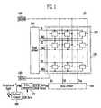
- FIG. 1illustrates a schematic view of an OLED display 10 according to an example embodiment.
- the OLED display 10may include a pixel portion 100 , a scan driver 200 , a data driver 300 , a data converter 400 , and an optical sensor 500 . It should be appreciated that other devices and/or elements may be included or excluded in the OLED display 10 .
- the pixel portion 100may include a plurality of pixels 110 , which may be connected to emission control lines EM 1 to EMn and data lines D 1 to Dm.
- one pixel 110may include an OLED, and may be composed of at least two subpixels for emitting light of different colors, e.g., red, green and blue. It should be appreciated that other configuration of the subpixels may be employed.
- the pixel portion 100may display images corresponding to a voltage of a first power supply ELVdd 120 , and a voltage of a second power supply ELVss 140 .
- the pixel portion 100may further display images corresponding to a scan signal supplied by the scan lines S 1 , S 2 , . . . , Sn and an emission control signal supplied by the emission control lines EM 1 , EM 2 , . . . , EMn generated from the scan driver 200 , and a data signal supplied by the data lines D 1 , D 2 , . . . , Dm generated from the data driver 300 .
- the scan signals generated by the scan driver 200may be sequentially supplied to respective scan lines S 1 to Sn, and the emission control signals also generated by the scan driver 200 may be sequentially supplied to respective emission control lines EM 1 to EMn. It should be appreciated that the scan signals and the emission control signals may also be non-sequentially supplied to the scan lines S 1 to Sn and the emission control lines EM 1 to EMn, respectively.
- the data driver 300may receive image data R′G′B′ Data (or RGB Data) from the data converter 400 and may generate data signals corresponding thereto.
- the data signals generated by the data driver 300may be supplied to the data lines D 1 to Dm in synchronization with the scan signal and may be transferred to each pixel 110 . It should be appreciated that the data signals may also be supplied to the data lines D 1 to Dm in a non-synchronization manner with the scan signal.
- the data converter 400may select one of the states (e.g., a changed or a non-changed state) of the input image data RGB Data according to an optical sensing signal S sens input from an optical sensor 500 . Further, the data converter 400 may store changed data R′G′B′ Data, which may be obtained by changing input image data RGB Data or input image data RGB Data.
- statese.g., a changed or a non-changed state
- the data converter 400may store changed data R′G′B′ Data, which may be obtained by changing input image data RGB Data or input image data RGB Data.
- the data converter 400may generate and store changed data R′G′B′ Data when a change of the input image data RGB Data is necessary.
- the changed data R′G′B′ Datamay be obtained by changing a luminance value and/or saturation value of the input image data RGB Data.
- the data converter 400may store the input image data RGB Data supplied thereto.
- the changed data R′G′B′ Data and/or the input image data RGB Data stored in the data converter 400may be input to the data driver 300 .
- the optical sensor 500may include an optical sensing device, i.e., a transistor or a photo diode, and may sense an intensity of peripheral or ambient light. The optical sensor 500 may then generate an optical sensing signal S sens corresponding to the sensed intensity of the peripheral or ambient light. The optical sensing signal S sens generated by the optical sensor 500 may then be supplied to the data converter 400 .
- an optical sensing devicei.e., a transistor or a photo diode
- the data converter 400may generate the changed data R′G′B′ Data so as to enhance the visibility when the optical sensing signal S sens is greater than a predetermined reference value.
- the changed data R′G′B′ Datamay be obtained by changing the input image data RGB Data. For example, when the optical sensing signal S sens corresponding to light intensity greater than the predetermined reference value is supplied, the data converter 400 may generate the changed data R′G′B′ Data to control an improvement of the visibility.
- the changed data R′G′B′ Datamay be obtained by increasing a saturation of the input image data RGB Data.
- the input image data RGB Datamay be changed according to ambient environment conditions, e.g., an intensity of peripheral or ambient light, in order to improve the visibility of an image displayed in the pixel portion 100 .
- ambient environment conditionse.g., an intensity of peripheral or ambient light
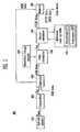
- the data converter 400may include a comparator 410 , a controller 420 , a first calculator 430 , a saturation change matrix 435 , a second calculator 440 , a reference look-up table 445 , and a memory 450 . It should be appreciated that other components and/or devices may be included or excluded in the data converter 400 .
- the comparator 410may compare an optical sensing signal S sens supplied from the optical sensor 500 with a predetermined reference value and may output a corresponding selection signal S sel .
- the comparator 410may output a selection signal S sel so that the input image data RGB Data is not changed.
- the comparator 410may output a selection signal S sel to change the input image data RGB Data.
- the selection signal S sel output from the comparator 410may then be provided to the controller 420 .
- the controller 420may determine a state (e.g., changed or a non-changed) of the input image data RGB Data corresponding to the input selection signal S sel .
- the controller 420may further transfer and/or store the input image data RGB Data to the first calculator 430 or, alternatively, to the memory 450 according to the determined changed or non-changed input image data RGB Data.
- the controller 420may transfer the input image data RGB Data to the first calculator 430 . Further, when the non-changed input image data RGB Data is selected, the controller 420 may store the input image data RGB Data in the memory 450 .
- the first calculator 430may generate pixel saturation data S out corresponding to the input image data RGB Data from the controller 420 while referencing the saturation change matrix 435 .
- the first calculator 430may calculate input data Rin, Gin, and Bin by subpixels along with the saturation change matrix 435 so as to obtain destination saturation data Rs, Gs, and Bs by subpixels, and may generate the pixel saturation data S out using the same.
- the destination saturation data Rs, Gs, and Bs by subpixelsmay be calculated using the saturation change matrix 435 .
- a method for calculating the destination saturation data Rs, Gs, and Bs by subpixelswill be explained later with reference to FIG. 3A to FIG. 3D .
- the pixel saturation data S outmay be calculated from the destination saturation data Rs, Gs, and Bs by subpixels.
- the pixel saturation data S outmay be set to a maximum value among the destination saturation data Rs, Gs, and Bs by subpixels or, alternatively, to a predetermined value corresponding to a difference between a maximum value and a minimum value of the destination saturation data Rs, Gs, and Bs by subpixels.
- the pixel saturation data S out generated by the first calculator 430may be provided to the second calculator 440 .
- the second calculator 440may extract the changed data R′G′B′ Data from the reference look-up table 445 corresponding to the pixel saturation data S out supplied from the first calculator 430 , and may store the changed data R′G′B′ Data in the memory 450 .
- the second calculator 440may extract the changed data R′G′B′ Data having desired saturation and luminance values by referencing a saturation look-up table (LUT) and a luminance look-up table (LUT) stored in the reference look-up table 445 .
- the saturation LUT and the luminance LUTmay include tables to extract a saturation change value and a luminance change value corresponding to the pixel saturation data S out , respectively.
- the second calculator 440may extract the changed data R′G′B′ Data by referencing two values adjacent to the pixel saturation data S out (e.g., values stored in the reference look-up table 445 ).
- the second calculator 440may linearly interpolate the changed values, which may correspond to a maximum value among values less than input pixel saturation data S out and a minimum value among values greater than the pixel saturation data S out , in order to extract the changed data R′G′B′ Data.
- the memory 450may store the input image data RGB Data from the controller 420 or the changed data R′G′B′ Data from the second calculator 440 .
- the input image data RGB Data or the changed data R′G′B′ Datamay be stored in the memory 450 .
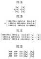
- the first calculator 430may multiply the saturation change matrix A by input data Rin, Gin and Bin by subpixels, included in the input image data RGB Data, to obtain destination saturation data Rs, Gs and Bs by subpixels.
- the saturation change matrix Amay also be a matrix to adjust the saturation using a saturation factor k to determine a saturation adjustment. Further, the saturation change matrix A may be used to convert values of the input data Rin, Gin and Bin by subpixels by a previously selected saturation factor k so as to calculate the data Rs, Gs and Bs by subpixels.
- the saturation change matrix Amay be set in consideration of a white balance of a pixel, and/or the matrix (as shown in FIG. 3B ) may be generally used as the saturation change matrix A.
- the saturation factor kWhen the saturation factor k is greater than 1, the saturation may be increased. Alternatively, when the saturation factor k is less than 1, the saturation may be reduced. When the saturation factor k is 1 (e.g., the saturation change matrix A is a unit matrix of 3 ⁇ 3), the saturation may remain the same, i.e., unchanged (as illustrated in FIG. 3C ).
- the saturation factor kis zero, as illustrated in FIG. 3B .
- the saturation factor kis zero, the saturation may be changed to a gray image having no saturation, as illustrated in FIG. 3D .
- FIG. 4illustrates a flow chart of a driving method of the data converter 400 shown in FIG. 2 .
- the comparator 410may compare the optical sensing signal S sens with a predetermined reference value and may generate a corresponding selection signal S sel .
- the selection signal S selmay be a signal to control a state (e.g., change or a non-change) of data. For example, when the intensity of the peripheral light is less than the predetermined reference value, the selection signal is set to ‘0’ indicating a ‘not changed’ state. Further, when the intensity of the peripheral light is equal to or greater than the predetermined reference value, the selection signal can become a signal of 1 bit set to ‘1’ indicating a ‘changed’ state.
- the selection signal S sel generated by the comparator 410may be input to the controller 420 .
- the controller 420may determine whether a change or a non-change input image data RGB Data corresponding to the selection signal S sel is determined (S 200 ). Accordingly, when the selection signal S sel for controlling data not be changed is input to the controller 420 , the controller 420 may not change the input image data RGB Data supplied thereto, and may supply the data to the data driver 300 .
- the input image data RGB Datamay be temporarily stored in the memory 450 and may be input to the data driver 300 under a control of the controller 420 .
- the controller 420may transfer the input image data RGB Data supplied thereto to the first calculator 430 .
- the first calculator 430may calculate the input image data RGB Data and the saturation change matrix 435 to obtain the destination saturation data Rs, Gs, and Bs by subpixels (S 300 ), and may generate and provide a corresponding pixel saturation data S out to the second calculator 440 (S 300 ).
- the second calculator 440may then extract changed data R′G′B′ Data from the reference look-up table 445 corresponding to the pixel saturation data S out (S 500 ) and may store the changed data R′G′B′ Data in the memory 450 (S 600 ).
- the changed data R′G′B′ Datamay be the input image data RGB Data, in which the saturation and/or luminance of the input image data RGB Data may be changed, from the reference look-up table unit 445 . Further, when the changed data R′G′B′ Data corresponding to the pixel saturation data S out supplied from the first calculator 430 is not stored in the reference look-up table 445 , the second calculator 440 may extract and store the changed data R′G′B′ Data corresponding to the pixel saturation data S out by, for example, a linear interpolation in the memory 450 .
- the changed data R′G′B′ Data stored in the memory 450may be input to the data driver 300 (S 700 ), so that the data may be used to generate a data signal.
- Example embodimentsrelate to an OLED display and driving methods thereof providing an input image data that may be dynamically changed corresponding to an ambient environment, i.e., based on the intensity of peripheral light, in order to improve and enhance the quality, visibility and/or viewability of the display device. For example, when an OLED display is exposed to peripheral light greater than a predetermined reference value, changed data may be generated and a corresponding changed image may be displayed, so that the visibility and/or viewability of the display device may be improved under the changing ambient or peripheral light conditions, e.g., solar light.
- the changed datamay be obtained by increasing a saturation of the input image data.
- first and secondmay be used herein to describe various elements, structures, components, regions, layers and/or sections, these elements, structures, components, regions, layers and/or sections should not be limited by these terms. These terms are only used to distinguish one element, structure, component, region, layer and/or section from another element, structure, component, region, layer and/or section. Thus, a first element, structure, component, region, layer or section discussed below could be termed a second element, structure, component, region, layer or section without departing from the teachings of example embodiments.
Landscapes
- Engineering & Computer Science (AREA)
- Physics & Mathematics (AREA)
- General Physics & Mathematics (AREA)
- Computer Hardware Design (AREA)
- Theoretical Computer Science (AREA)
- Spectroscopy & Molecular Physics (AREA)
- Control Of El Displays (AREA)
- Control Of Indicators Other Than Cathode Ray Tubes (AREA)
- Electroluminescent Light Sources (AREA)
Abstract
Description
Claims (15)
Applications Claiming Priority (2)
| Application Number | Priority Date | Filing Date | Title |
|---|---|---|---|
| KR10-2007-0018695 | 2007-02-23 | ||
| KR1020070018695AKR100844781B1 (en) | 2007-02-23 | 2007-02-23 | Organic EL display device and driving method thereof |
Publications (2)
| Publication Number | Publication Date |
|---|---|
| US20080204380A1 US20080204380A1 (en) | 2008-08-28 |
| US8059073B2true US8059073B2 (en) | 2011-11-15 |
Family
ID=39386385
Family Applications (1)
| Application Number | Title | Priority Date | Filing Date |
|---|---|---|---|
| US12/007,452Active2030-08-27US8059073B2 (en) | 2007-02-23 | 2008-01-10 | Organic light emitting diode display and driving method thereof |
Country Status (5)
| Country | Link |
|---|---|
| US (1) | US8059073B2 (en) |
| EP (1) | EP1962265B1 (en) |
| JP (1) | JP2008209883A (en) |
| KR (1) | KR100844781B1 (en) |
| CN (1) | CN101251984B (en) |
Cited By (1)
| Publication number | Priority date | Publication date | Assignee | Title |
|---|---|---|---|---|
| US9659532B2 (en) | 2008-07-14 | 2017-05-23 | Global Oled Technology Llc | Four-channel transmissive display system |
Families Citing this family (30)
| Publication number | Priority date | Publication date | Assignee | Title |
|---|---|---|---|---|
| US20090256830A1 (en)* | 2008-04-14 | 2009-10-15 | Sony Ericsson Mobile Communications Ab | Hybrid display |
| KR20100003459A (en)* | 2008-07-01 | 2010-01-11 | 삼성모바일디스플레이주식회사 | Organic light emitting display device and driving method thereof |
| US8300056B2 (en) | 2008-10-13 | 2012-10-30 | Apple Inc. | Seamless display migration |
| US9135889B2 (en) | 2008-10-14 | 2015-09-15 | Apple Inc. | Color correction of electronic displays |
| US9165493B2 (en) | 2008-10-14 | 2015-10-20 | Apple Inc. | Color correction of electronic displays utilizing gain control |
| US9063713B2 (en) | 2008-10-28 | 2015-06-23 | Apple Inc. | Graphics controllers with increased thermal management granularity |
| US8508538B2 (en) | 2008-12-31 | 2013-08-13 | Apple Inc. | Timing controller capable of switching between graphics processing units |
| US8243426B2 (en) | 2008-12-31 | 2012-08-14 | Apple Inc. | Reducing optical effects in a display |
| US9542914B2 (en) | 2008-12-31 | 2017-01-10 | Apple Inc. | Display system with improved graphics abilities while switching graphics processing units |
| US8207974B2 (en) | 2008-12-31 | 2012-06-26 | Apple Inc. | Switch for graphics processing units |
| JP2010160272A (en)* | 2009-01-07 | 2010-07-22 | Canon Inc | Display control device and control method thereof |
| US8648868B2 (en) | 2010-01-06 | 2014-02-11 | Apple Inc. | Color correction to facilitate switching between graphics-processing units |
| US8797334B2 (en) | 2010-01-06 | 2014-08-05 | Apple Inc. | Facilitating efficient switching between graphics-processing units |
| US9176536B2 (en) | 2011-09-30 | 2015-11-03 | Apple, Inc. | Wireless display for electronic devices |
| US9810942B2 (en) | 2012-06-15 | 2017-11-07 | Apple Inc. | Quantum dot-enhanced display having dichroic filter |
| US9728124B2 (en)* | 2013-05-08 | 2017-08-08 | Apple Inc. | Adaptive RGB-to-RGBW conversion for RGBW display systems |
| DK3134553T3 (en) | 2014-04-24 | 2019-11-18 | Lucira Health Inc | COLORIMETRIC DETECTION OF NUCLEIC ACID AMPLIFICATION |
| WO2017160839A1 (en) | 2016-03-14 | 2017-09-21 | Diassess Inc. | Devices and methods for modifying optical properties |
| EP3430372A4 (en) | 2016-03-14 | 2019-10-16 | Lucira Health, Inc. | DEVICES AND METHODS FOR PREPARING AND DELIVERING BIOLOGICAL TEST SAMPLE |
| AU2017232340B2 (en) | 2016-03-14 | 2022-04-28 | Pfizer Inc. | Systems and methods for performing biological assays |
| WO2017160840A1 (en) | 2016-03-14 | 2017-09-21 | Diassess Inc. | Selectively vented biological assay devices and associated methods |
| CN106935190B (en)* | 2017-02-22 | 2019-02-05 | 上海天马有机发光显示技术有限公司 | A kind of organic light emitting display panel, organic light-emitting display device, organic light emitting display panel driving method |
| US11080848B2 (en) | 2017-04-06 | 2021-08-03 | Lucira Health, Inc. | Image-based disease diagnostics using a mobile device |
| US10549275B2 (en) | 2017-09-14 | 2020-02-04 | Lucira Health, Inc. | Multiplexed biological assay device with electronic readout |
| WO2019055135A1 (en) | 2017-09-14 | 2019-03-21 | Diassess Inc. | Multiplexed biological assay device with electronic readout |
| JP2022504506A (en)* | 2018-10-09 | 2022-01-13 | ルシラ ヘルス インコーポレイテッド | How to Diagnose Consumer-Based Diseases |
| USD910200S1 (en) | 2018-12-21 | 2021-02-09 | Lucira Health, Inc. | Test tube |
| USD907232S1 (en) | 2018-12-21 | 2021-01-05 | Lucira Health, Inc. | Medical testing device |
| USD953561S1 (en) | 2020-05-05 | 2022-05-31 | Lucira Health, Inc. | Diagnostic device with LED display |
| USD962470S1 (en) | 2020-06-03 | 2022-08-30 | Lucira Health, Inc. | Assay device with LCD display |
Citations (22)
| Publication number | Priority date | Publication date | Assignee | Title |
|---|---|---|---|---|
| KR900003762A (en) | 1988-08-31 | 1990-03-27 | 아오이 죠이치 | High Speed Saturation Inverter |
| US20010050757A1 (en) | 2000-05-15 | 2001-12-13 | Yasuhiro Yoshida | Image display device and electronic apparatus using same, and image display method of same |
| JP2003228330A (en) | 2002-02-01 | 2003-08-15 | Sanyo Electric Co Ltd | Display device |
| US20030231160A1 (en) | 2002-06-13 | 2003-12-18 | Fujitsu Limited | Display device |
| US20040196303A1 (en)* | 2003-01-23 | 2004-10-07 | Seiko Epson Corporation | Image processing system, projector, program, information storage medium, and image processing method |
| US20040222999A1 (en)* | 2003-05-07 | 2004-11-11 | Beohm-Rock Choi | Four-color data processing system |
| JP2004325565A (en) | 2003-04-22 | 2004-11-18 | Matsushita Electric Ind Co Ltd | EL color display correction device |
| US6823083B1 (en)* | 1999-11-25 | 2004-11-23 | Fuji Photo Film Co., Ltd. | Saturation correcting apparatus and method |
| KR20050011297A (en) | 2003-07-22 | 2005-01-29 | 삼성전자주식회사 | Display apparatus and control method thereof |
| US20050073516A1 (en)* | 2003-10-01 | 2005-04-07 | Mun-Seok Kang | Electron emission device and driving method thereof |
| US20050087671A1 (en) | 2003-10-28 | 2005-04-28 | Samsung Electronics Co., Ltd. | Display and control method thereof |
| JP2005253050A (en) | 2004-02-02 | 2005-09-15 | Canon Inc | Adjustment circuit and method |
| WO2006088118A1 (en) | 2005-02-18 | 2006-08-24 | Pioneer Corporation | Display control device and display device |
| JP2006243454A (en) | 2005-03-04 | 2006-09-14 | Mitsubishi Electric Corp | Image display device |
| JP2006267140A (en) | 2005-03-22 | 2006-10-05 | Hitachi Ltd | Video processing device and portable terminal device |
| CN1855202A (en) | 2005-04-28 | 2006-11-01 | 三星Sdi株式会社 | Light emitting display and drive method thereof |
| KR20060120643A (en) | 2003-09-11 | 2006-11-27 | 마쯔시다덴기산교 가부시키가이샤 | Image processing apparatus, image processing method and image processing program |
| JP2006337997A (en) | 2005-05-02 | 2006-12-14 | Semiconductor Energy Lab Co Ltd | Display device |
| JP2006350316A (en) | 2005-05-20 | 2006-12-28 | Semiconductor Energy Lab Co Ltd | Display device and electronic equipment |
| US20070040774A1 (en)* | 2005-08-22 | 2007-02-22 | Lee Jae-Sung | Organic light emitting display device having automatic brightness control apparatus |
| US20070188623A1 (en) | 2003-09-11 | 2007-08-16 | Haruo Yamashita | Visual processing device, visual processing method, visual processing program, intergrated circuit, display device, image-capturing device, and portable information terminal |
| KR101054440B1 (en) | 2009-04-27 | 2011-08-05 | 삼성전기주식회사 | Electronic device package and manufacturing method thereof |
- 2007
- 2007-02-23KRKR1020070018695Apatent/KR100844781B1/enactiveActive
- 2007-04-25JPJP2007116014Apatent/JP2008209883A/enactivePending
- 2008
- 2008-01-10USUS12/007,452patent/US8059073B2/enactiveActive
- 2008-02-22CNCN2008100805857Apatent/CN101251984B/enactiveActive
- 2008-02-22EPEP08101868.1Apatent/EP1962265B1/enactiveActive
Patent Citations (26)
| Publication number | Priority date | Publication date | Assignee | Title |
|---|---|---|---|---|
| US5315694A (en)* | 1988-08-31 | 1994-05-24 | Kabushiki Kaisha Toshiba | High-speed color saturation converter for digital color data |
| KR900003762A (en) | 1988-08-31 | 1990-03-27 | 아오이 죠이치 | High Speed Saturation Inverter |
| US6823083B1 (en)* | 1999-11-25 | 2004-11-23 | Fuji Photo Film Co., Ltd. | Saturation correcting apparatus and method |
| US20010050757A1 (en) | 2000-05-15 | 2001-12-13 | Yasuhiro Yoshida | Image display device and electronic apparatus using same, and image display method of same |
| JP2003228330A (en) | 2002-02-01 | 2003-08-15 | Sanyo Electric Co Ltd | Display device |
| US20030231160A1 (en) | 2002-06-13 | 2003-12-18 | Fujitsu Limited | Display device |
| US20040196303A1 (en)* | 2003-01-23 | 2004-10-07 | Seiko Epson Corporation | Image processing system, projector, program, information storage medium, and image processing method |
| JP2004325565A (en) | 2003-04-22 | 2004-11-18 | Matsushita Electric Ind Co Ltd | EL color display correction device |
| US20040222999A1 (en)* | 2003-05-07 | 2004-11-11 | Beohm-Rock Choi | Four-color data processing system |
| KR20050011297A (en) | 2003-07-22 | 2005-01-29 | 삼성전자주식회사 | Display apparatus and control method thereof |
| KR20060120643A (en) | 2003-09-11 | 2006-11-27 | 마쯔시다덴기산교 가부시키가이샤 | Image processing apparatus, image processing method and image processing program |
| US20070188623A1 (en) | 2003-09-11 | 2007-08-16 | Haruo Yamashita | Visual processing device, visual processing method, visual processing program, intergrated circuit, display device, image-capturing device, and portable information terminal |
| US20070165048A1 (en) | 2003-09-11 | 2007-07-19 | Matsushita Electric Industrial Co., Ltd. | Image processing device, image processing method, and image processing program |
| US20050073516A1 (en)* | 2003-10-01 | 2005-04-07 | Mun-Seok Kang | Electron emission device and driving method thereof |
| US20050087671A1 (en) | 2003-10-28 | 2005-04-28 | Samsung Electronics Co., Ltd. | Display and control method thereof |
| JP2005253050A (en) | 2004-02-02 | 2005-09-15 | Canon Inc | Adjustment circuit and method |
| WO2006088118A1 (en) | 2005-02-18 | 2006-08-24 | Pioneer Corporation | Display control device and display device |
| JP2006243454A (en) | 2005-03-04 | 2006-09-14 | Mitsubishi Electric Corp | Image display device |
| JP2006267140A (en) | 2005-03-22 | 2006-10-05 | Hitachi Ltd | Video processing device and portable terminal device |
| CN1855202A (en) | 2005-04-28 | 2006-11-01 | 三星Sdi株式会社 | Light emitting display and drive method thereof |
| KR20060113009A (en) | 2005-04-28 | 2006-11-02 | 삼성에스디아이 주식회사 | Light emitting display device and driving method thereof |
| US20060244697A1 (en) | 2005-04-28 | 2006-11-02 | Lee Jae S | Light emitting display device and method of driving the same |
| JP2006337997A (en) | 2005-05-02 | 2006-12-14 | Semiconductor Energy Lab Co Ltd | Display device |
| JP2006350316A (en) | 2005-05-20 | 2006-12-28 | Semiconductor Energy Lab Co Ltd | Display device and electronic equipment |
| US20070040774A1 (en)* | 2005-08-22 | 2007-02-22 | Lee Jae-Sung | Organic light emitting display device having automatic brightness control apparatus |
| KR101054440B1 (en) | 2009-04-27 | 2011-08-05 | 삼성전기주식회사 | Electronic device package and manufacturing method thereof |
Non-Patent Citations (2)
| Title |
|---|
| Chinese Office Action in CN 2008100805857, dated Dec. 15, 2010 (Shin, et al.) Chinese Office Action from prosecution of corresponding Chinese application. |
| Japanese Office Action in JP 2007-116014, dated Sep. 28, 2010 (Shin, et al.) Japanese Office Action from prosecution of corresponding Japanese application. |
Cited By (1)
| Publication number | Priority date | Publication date | Assignee | Title |
|---|---|---|---|---|
| US9659532B2 (en) | 2008-07-14 | 2017-05-23 | Global Oled Technology Llc | Four-channel transmissive display system |
Also Published As
| Publication number | Publication date |
|---|---|
| JP2008209883A (en) | 2008-09-11 |
| KR100844781B1 (en) | 2008-07-07 |
| EP1962265B1 (en) | 2016-02-17 |
| EP1962265A1 (en) | 2008-08-27 |
| US20080204380A1 (en) | 2008-08-28 |
| CN101251984B (en) | 2010-12-15 |
| CN101251984A (en) | 2008-08-27 |
Similar Documents
| Publication | Publication Date | Title |
|---|---|---|
| US8059073B2 (en) | Organic light emitting diode display and driving method thereof | |
| US8059069B2 (en) | Organic light emitting diode display device and driving method thereof | |
| KR101966393B1 (en) | Display device and driving method thereof | |
| US8330754B2 (en) | Organic light emitting diode display and driving method thereof | |
| US8154478B2 (en) | Organic electro luminescence display and driving method thereof | |
| US20080088548A1 (en) | Organic light emitting diode display device and driving method thereof | |
| US8330684B2 (en) | Organic light emitting display and its driving method | |
| WO2006106451A1 (en) | A led display system | |
| US20090033685A1 (en) | Organic light emitting display and driving method thereof | |
| US8427399B2 (en) | Organic light emitting display device including signal processor for modifying image data and driving method thereof | |
| JP2021517976A (en) | Color correction method and device, device, display device, storage medium | |
| KR100753318B1 (en) | Display device | |
| KR20210134162A (en) | Display device and method of driving the same | |
| US20140300625A1 (en) | Display device and method of compensating colors of the display device | |
| KR102185118B1 (en) | Organic light emitting display and driving method thereof | |
| CN114495839B (en) | A method and device for out-of-plane voltage drop compensation of a display panel | |
| KR101968911B1 (en) | organic light-emitting dIODE DISPLAY DEVICE AND DRIVING METHOD THEREOF | |
| KR101843858B1 (en) | Self Light Emission Display Device And Its Driving Method | |
| KR20080082281A (en) | Organic light emitting display device and manufacturing method | |
| KR100815755B1 (en) | Gamma Correction Device and Organic Electroluminescence Display | |
| KR100667079B1 (en) | Auto Brightness Organic Electroluminescent Display | |
| KR100812000B1 (en) | Organic light emitting display device and driving method thereof | |
| US20080252650A1 (en) | Organic light emitting display, driver system therfor and driving method thereof | |
| KR102699356B1 (en) | Organic light emitting display device and method for correcting correction thereof | |
| KR100805121B1 (en) | Organic light emitting display device and driving method thereof |
Legal Events
| Date | Code | Title | Description |
|---|---|---|---|
| AS | Assignment | Owner name:SAMSUNG SDI CO., LTD, KOREA, REPUBLIC OF Free format text:ASSIGNMENT OF ASSIGNORS INTEREST;ASSIGNORS:SHIN, HYE-JIN;LEE, MYUNG-HO;REEL/FRAME:020386/0005 Effective date:20071120 Owner name:SAMSUNG SDI CO., LTD,KOREA, REPUBLIC OF Free format text:ASSIGNMENT OF ASSIGNORS INTEREST;ASSIGNORS:SHIN, HYE-JIN;LEE, MYUNG-HO;REEL/FRAME:020386/0005 Effective date:20071120 | |
| AS | Assignment | Owner name:SAMSUNG MOBILE DISPLAY CO., LTD., KOREA, REPUBLIC OF Free format text:ASSIGNMENT OF ASSIGNORS INTEREST;ASSIGNOR:SAMSUNG SDI CO., LTD.;REEL/FRAME:021998/0771 Effective date:20081212 Owner name:SAMSUNG MOBILE DISPLAY CO., LTD., KOREA, REPUBLIC Free format text:ASSIGNMENT OF ASSIGNORS INTEREST;ASSIGNOR:SAMSUNG SDI CO., LTD.;REEL/FRAME:021998/0771 Effective date:20081212 Owner name:SAMSUNG MOBILE DISPLAY CO., LTD.,KOREA, REPUBLIC O Free format text:ASSIGNMENT OF ASSIGNORS INTEREST;ASSIGNOR:SAMSUNG SDI CO., LTD.;REEL/FRAME:021998/0771 Effective date:20081212 | |
| FEPP | Fee payment procedure | Free format text:PAYOR NUMBER ASSIGNED (ORIGINAL EVENT CODE: ASPN); ENTITY STATUS OF PATENT OWNER: LARGE ENTITY | |
| STCF | Information on status: patent grant | Free format text:PATENTED CASE | |
| AS | Assignment | Owner name:SAMSUNG DISPLAY CO., LTD., KOREA, REPUBLIC OF Free format text:MERGER;ASSIGNOR:SAMSUNG MOBILE DISPLAY CO., LTD.;REEL/FRAME:029203/0001 Effective date:20120827 | |
| FPAY | Fee payment | Year of fee payment:4 | |
| MAFP | Maintenance fee payment | Free format text:PAYMENT OF MAINTENANCE FEE, 8TH YEAR, LARGE ENTITY (ORIGINAL EVENT CODE: M1552); ENTITY STATUS OF PATENT OWNER: LARGE ENTITY Year of fee payment:8 | |
| MAFP | Maintenance fee payment | Free format text:PAYMENT OF MAINTENANCE FEE, 12TH YEAR, LARGE ENTITY (ORIGINAL EVENT CODE: M1553); ENTITY STATUS OF PATENT OWNER: LARGE ENTITY Year of fee payment:12 |