US8059059B2 - Slidable choke microwave antenna - Google Patents
Slidable choke microwave antennaDownload PDFInfo
- Publication number
- US8059059B2 US8059059B2US12/129,482US12948208AUS8059059B2US 8059059 B2US8059059 B2US 8059059B2US 12948208 AUS12948208 AUS 12948208AUS 8059059 B2US8059059 B2US 8059059B2
- Authority
- US
- United States
- Prior art keywords
- outer jacket
- feedline
- slidable outer
- slidable
- radiating portion
- Prior art date
- Legal status (The legal status is an assumption and is not a legal conclusion. Google has not performed a legal analysis and makes no representation as to the accuracy of the status listed.)
- Expired - Fee Related, expires
Links
- 239000004020conductorSubstances0.000claimsabstractdescription72
- 239000012212insulatorSubstances0.000claimsabstractdescription14
- 238000002679ablationMethods0.000claimsdescription15
- 229910052751metalInorganic materials0.000claimsdescription14
- 239000002184metalSubstances0.000claimsdescription14
- 238000000034methodMethods0.000claimsdescription12
- 239000011248coating agentSubstances0.000claimsdescription7
- 238000000576coating methodMethods0.000claimsdescription7
- 150000002736metal compoundsChemical class0.000claimsdescription2
- 239000012530fluidSubstances0.000description125
- 238000001816coolingMethods0.000description26
- 239000002826coolantSubstances0.000description19
- 239000000463materialSubstances0.000description11
- 239000007787solidSubstances0.000description9
- 229910000679solderInorganic materials0.000description8
- 239000010935stainless steelSubstances0.000description7
- 229910001220stainless steelInorganic materials0.000description7
- 229920001343polytetrafluoroethylenePolymers0.000description6
- 239000004810polytetrafluoroethyleneSubstances0.000description6
- RYGMFSIKBFXOCR-UHFFFAOYSA-NCopperChemical compound[Cu]RYGMFSIKBFXOCR-UHFFFAOYSA-N0.000description5
- 229910052802copperInorganic materials0.000description5
- 239000010949copperSubstances0.000description5
- 238000003780insertionMethods0.000description5
- 230000037431insertionEffects0.000description5
- 150000002739metalsChemical class0.000description5
- 239000004812Fluorinated ethylene propyleneSubstances0.000description4
- FAPWRFPIFSIZLT-UHFFFAOYSA-MSodium chlorideChemical compound[Na+].[Cl-]FAPWRFPIFSIZLT-UHFFFAOYSA-M0.000description4
- ATJFFYVFTNAWJD-UHFFFAOYSA-NTinChemical compound[Sn]ATJFFYVFTNAWJD-UHFFFAOYSA-N0.000description4
- 229910045601alloyInorganic materials0.000description4
- 239000000956alloySubstances0.000description4
- 230000003139buffering effectEffects0.000description4
- 238000004891communicationMethods0.000description4
- 239000008367deionised waterSubstances0.000description4
- 229910021641deionized waterInorganic materials0.000description4
- 239000003989dielectric materialSubstances0.000description4
- 229920009441perflouroethylene propylenePolymers0.000description4
- -1polytetrafluoroethylenePolymers0.000description4
- 239000011780sodium chlorideSubstances0.000description4
- 229910052718tinInorganic materials0.000description4
- 239000011135tinSubstances0.000description4
- XLYOFNOQVPJJNP-UHFFFAOYSA-NwaterChemical compoundOXLYOFNOQVPJJNP-UHFFFAOYSA-N0.000description4
- 229920006362Teflon®Polymers0.000description3
- 230000000712assemblyEffects0.000description3
- 238000000429assemblyMethods0.000description3
- 210000004027cellAnatomy0.000description3
- 238000010276constructionMethods0.000description3
- 230000007423decreaseEffects0.000description3
- 230000005404monopoleEffects0.000description3
- 229920000642polymerPolymers0.000description3
- 239000002861polymer materialSubstances0.000description3
- 125000006850spacer groupChemical group0.000description3
- 206010028980NeoplasmDiseases0.000description2
- PXHVJJICTQNCMI-UHFFFAOYSA-NNickelChemical compound[Ni]PXHVJJICTQNCMI-UHFFFAOYSA-N0.000description2
- 239000004952PolyamideSubstances0.000description2
- 238000005266castingMethods0.000description2
- 230000008859changeEffects0.000description2
- 238000010586diagramMethods0.000description2
- HQQADJVZYDDRJT-UHFFFAOYSA-Nethene;prop-1-eneChemical groupC=C.CC=CHQQADJVZYDDRJT-UHFFFAOYSA-N0.000description2
- 230000000149penetrating effectEffects0.000description2
- 239000004033plasticSubstances0.000description2
- 229920003023plasticPolymers0.000description2
- 229920002647polyamidePolymers0.000description2
- 210000004881tumor cellAnatomy0.000description2
- PNEYBMLMFCGWSK-UHFFFAOYSA-NAluminaChemical compound[O-2].[O-2].[O-2].[Al+3].[Al+3]PNEYBMLMFCGWSK-UHFFFAOYSA-N0.000description1
- 239000004593EpoxySubstances0.000description1
- 239000004642PolyimideSubstances0.000description1
- RTAQQCXQSZGOHL-UHFFFAOYSA-NTitaniumChemical compound[Ti]RTAQQCXQSZGOHL-UHFFFAOYSA-N0.000description1
- 229920004738ULTEM®Polymers0.000description1
- 239000000853adhesiveSubstances0.000description1
- 230000001070adhesive effectEffects0.000description1
- 230000005779cell damageEffects0.000description1
- 208000037887cell injuryDiseases0.000description1
- 229910010293ceramic materialInorganic materials0.000description1
- 230000015271coagulationEffects0.000description1
- 238000005345coagulationMethods0.000description1
- 230000007797corrosionEffects0.000description1
- 238000005260corrosionMethods0.000description1
- 230000006378damageEffects0.000description1
- 230000008021depositionEffects0.000description1
- 201000010099diseaseDiseases0.000description1
- 208000037265diseases, disorders, signs and symptomsDiseases0.000description1
- 239000006185dispersionSubstances0.000description1
- 238000006073displacement reactionMethods0.000description1
- 230000009977dual effectEffects0.000description1
- 230000005670electromagnetic radiationEffects0.000description1
- 125000003700epoxy groupChemical group0.000description1
- 238000001125extrusionMethods0.000description1
- PCHJSUWPFVWCPO-UHFFFAOYSA-NgoldChemical compound[Au]PCHJSUWPFVWCPO-UHFFFAOYSA-N0.000description1
- 229910052737goldInorganic materials0.000description1
- 239000010931goldSubstances0.000description1
- 239000003779heat-resistant materialSubstances0.000description1
- 238000009217hyperthermia therapyMethods0.000description1
- 238000001746injection mouldingMethods0.000description1
- 230000000266injurious effectEffects0.000description1
- 230000002427irreversible effectEffects0.000description1
- 230000003211malignant effectEffects0.000description1
- 230000013011matingEffects0.000description1
- 238000002844meltingMethods0.000description1
- 230000008018meltingEffects0.000description1
- 238000012986modificationMethods0.000description1
- 230000004048modificationEffects0.000description1
- 229910052759nickelInorganic materials0.000description1
- 230000035515penetrationEffects0.000description1
- 229920003223poly(pyromellitimide-1,4-diphenyl ether)Polymers0.000description1
- 229920000647polyepoxidePolymers0.000description1
- 229920001721polyimidePolymers0.000description1
- 229920001296polysiloxanePolymers0.000description1
- 230000001681protective effectEffects0.000description1
- 230000005855radiationEffects0.000description1
- 229920005989resinPolymers0.000description1
- 239000011347resinSubstances0.000description1
- 229910052709silverInorganic materials0.000description1
- 239000004332silverSubstances0.000description1
- 238000005476solderingMethods0.000description1
- 239000012815thermoplastic materialSubstances0.000description1
- 229920005992thermoplastic resinPolymers0.000description1
- 230000008467tissue growthEffects0.000description1
- 239000010936titaniumSubstances0.000description1
- 229910052719titaniumInorganic materials0.000description1
- 238000012546transferMethods0.000description1
Images


Classifications
- H—ELECTRICITY
- H01—ELECTRIC ELEMENTS
- H01Q—ANTENNAS, i.e. RADIO AERIALS
- H01Q9/00—Electrically-short antennas having dimensions not more than twice the operating wavelength and consisting of conductive active radiating elements
- H01Q9/04—Resonant antennas
- H01Q9/16—Resonant antennas with feed intermediate between the extremities of the antenna, e.g. centre-fed dipole
- A—HUMAN NECESSITIES
- A61—MEDICAL OR VETERINARY SCIENCE; HYGIENE
- A61B—DIAGNOSIS; SURGERY; IDENTIFICATION
- A61B18/00—Surgical instruments, devices or methods for transferring non-mechanical forms of energy to or from the body
- A61B18/18—Surgical instruments, devices or methods for transferring non-mechanical forms of energy to or from the body by applying electromagnetic radiation, e.g. microwaves
- A61B18/1815—Surgical instruments, devices or methods for transferring non-mechanical forms of energy to or from the body by applying electromagnetic radiation, e.g. microwaves using microwaves
- A—HUMAN NECESSITIES
- A61—MEDICAL OR VETERINARY SCIENCE; HYGIENE
- A61B—DIAGNOSIS; SURGERY; IDENTIFICATION
- A61B18/00—Surgical instruments, devices or methods for transferring non-mechanical forms of energy to or from the body
- A61B2018/00005—Cooling or heating of the probe or tissue immediately surrounding the probe
- A61B2018/00011—Cooling or heating of the probe or tissue immediately surrounding the probe with fluids
- A61B2018/00023—Cooling or heating of the probe or tissue immediately surrounding the probe with fluids closed, i.e. without wound contact by the fluid
Definitions
- the present disclosurerelates generally to microwave applicators used in tissue ablation procedures. More particularly, the present disclosure is directed to a microwave applicator having a slidable jacket that acts an electrical termination choke.
- Treatment of certain diseasesrequires destruction of malignant tissue growths (e.g., tumors). It is known that tumor cells denature at elevated temperatures that are slightly lower than temperatures injurious to surrounding healthy cells. Therefore, known treatment methods, such as hyperthermia therapy, heat tumor cells to temperatures above 41° C., while maintaining adjacent healthy cells at lower temperatures to avoid irreversible cell damage. Such methods involve applying electromagnetic radiation to heat tissue and include ablation and coagulation of tissue. In particular, microwave energy is used to coagulate and/or ablate tissue to denature or kill the cancerous cells.
- Microwave energyis applied via microwave ablation antenna assemblies that penetrate tissue to reach tumors.
- microwave antennassuch as monopole and dipole.
- monopole and dipole antennasmicrowave energy radiates perpendicularly from the axis of the conductor.
- a monopole antennaincludes a single, elongated microwave conductor.
- Dipole antennasmay have a coaxial construction including an inner conductor and an outer conductor separated by a dielectric portion. More specifically, dipole microwave antennas are typically long, thin inner conductors that extend along a longitudinal axis of the antenna and are surrounded by an outer conductor. In certain variations, a portion or portions of the outer conductor may be selectively removed to enhance the outward radiation of energy.
- This type of microwave antenna constructionis typically referred to as a “leaky waveguide” or “leaky coaxial” antenna.
- microwave antennastend to have a narrow operational bandwidth, a wavelength range at which optimal operational efficiency is achieved, and hence, are incapable of consistently maintaining a predetermined impedance match between the microwave delivery system (e.g., generator, cable, etc.) and the tissue surrounding the microwave antenna. More specifically, as microwave energy is applied to tissue, the dielectric constant of the tissue immediately surrounding the microwave antenna decreases as the tissue is treated. The drop causes the wavelength of the microwave energy being applied to tissue to increase beyond the bandwidth of the antenna. As a result, there is a mismatch between the bandwidth of conventional microwave antenna and the microwave energy being applied. Thus, narrow band microwave antennas tend to detune over use hindering the effective delivery and dispersion of energy.
- the microwave delivery systeme.g., generator, cable, etc.
- a microwave antenna assemblyincludes a feedline having an inner conductor, an outer conductor and an inner insulator disposed therebetween and a radiating portion including a dipole antenna coupled to the feedline and a trocar coupled to the dipole antenna at a distal end thereof.
- the antenna assemblyalso includes a slidable outer jacket disposed about the radiating portion and the feedline. The slidable outer jacket being configured to slide about at least one of the radiating portion and the feedline from a closed configuration, in which the slidable outer jacket is mated with the trocar and a retracted configuration, in which the slidable outer jacket is retracted in a proximally exposing at least a portion the radiating portion.
- a microwave antenna assemblyincludes a feedline having an inner conductor, an outer conductor and an inner insulator disposed therebetween and a radiating portion including a dipole antenna coupled to the feedline and a trocar coupled to the dipole antenna at a distal end thereof.
- the assemblyalso includes an inner fluid, which is disposed around the outer conductor in electro-mechanical contact therewith.
- the inner fluid feed memberincludes a plurality of fluid lumens defined therein configured to supply a fluid to the radiating portion.
- the assemblyalso includes an outer fluid feed member, which is disposed around the inner fluid feed member in electro-mechanical contact therewith.
- the outer fluid feed memberalso includes a plurality of fluid lumens defined therein configured to withdraw the fluid from the radiating portion.
- a method for performing microwave ablationincludes the step of providing a microwave antenna.
- the antenna assemblyincludes a feedline having all inner conductor, an outer conductor and an inner insulator disposed therebetween and a radiating portion including a dipole antenna coupled to the feedline and a trocar coupled to the dipole antenna at a distal end thereof.
- the antenna assemblyalso includes a slidable outer jacket disposed about the radiating portion and the feedline. The slidable outer jacket is configured to slide about at least one of the radiating portion and the feedline.
- the methodalso includes the steps of moving the slidable outer jacket into a closed configuration, in which the slidable outer jacket is mated with the trocar, inserting the microwave antenna into tissue and moving the slidable outer jacket into a retracted configuration, in which the slidable outer jacket is retracted proximally to expose at least a portion of the radiating portion.
- FIG. 1is a schematic diagram of a microwave ablation system according to an embodiment of the present disclosure
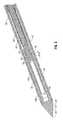
- FIGS. 2 and 3are perspective cross-sectional views of a microwave antenna assembly according to the present disclosure
- FIG. 4is an enlarged, cross-sectional view of a portion of the microwave antenna assembly of FIG. 2 ;
- FIG. 5is a perspective, cross-sectional view of a microwave antenna assembly of FIG. 2 ;
- FIG. 6is an enlarged, cross-sectional view of a portion of the microwave antenna assembly of FIG. 2 ;
- FIGS. 7-9are enlarged, cross-sectional views of a trocar of the microwave antenna assembly of FIG. 2 ;
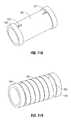
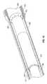
- FIGS. 10A-Bare perspective, cross-sectional views of a contact assembly of the microwave antenna assembly of FIG. 2 ;
- FIGS. 11A-Bare perspective views of the contact assembly of FIGS. 10A-B ;
- FIG. 12is a schematic diagram of a microwave ablation system according one embodiment of the present disclosure.
- FIG. 13is a perspective, cross-sectional view of a microwave antenna assembly according to the present disclosure.
- FIGS. 14-17are enlarged, cross-sectional views of a portion of the microwave antenna assembly of FIG. 12 .
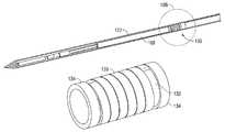
- FIG. 1shows a microwave ablation system 10 that includes a microwave antenna assembly 12 coupled to a microwave generator 14 via a flexible coaxial cable 16 .
- the generator 14is configured to provide microwave energy at an operational frequency from about 500 MHz to about 5000 MHz.
- the antenna assembly 12includes a radiating portion 18 that is connected by a feedline 20 (or shaft) to the cable 16 . More specifically, the antenna assembly 12 is coupled to the cable 16 through a connection hub 22 .
- the connection hub 22also includes an outlet fluid port 30 and an inlet fluid port 32 defined therein that are in fluid communication with the radiating portion 18 and the feedline 20 allowing dielectric coolant fluid 35 from the ports 30 and 32 to be dispersed and circulated around the antenna assembly 12 .
- the ports 30 and 32are also coupled to a supply pump 34 that, in turn, is coupled to a supply tank 36 that stores the dielectric coolant fluid 35 and maintains the fluid at a predetermined temperature.
- the supply tank 36may include a coolant unit (not shown), which cools the returning coolant fluid 35 from the antenna assembly 12 .
- the coolant fluidmay be a coolant gas.
- Assembly 12also includes a trocar 25 having tapered end 24 that terminates, in one embodiment, at a pointed tip 26 to facilitate insertion of the trocar into tissue with minimal resistance at a distal end of the radiating portion 18 .
- tip 26may be rounded or flat.
- FIG. 2illustrates the radiating portion 18 of the antenna assembly 12 having a slidable outer jacket 102 .
- the radiating portion 18has a substantially cylindrical shape and the outer jacket 102 has a substantially tubular shape defining an inner diameter substantially similar to the outer diameter of the radiating portion 18 .
- the outer jacket 102is configured to slide along the radiating portion 18 between a closed configuration and a retracted configuration. In the closed configuration, the jacket 102 is disposed at the distal end of the assembly 12 and the distal end of the jacket 102 is positioned in contact with the trocar 25 as shown in FIG. 8 . In the retracted configuration, the jacket 102 is slid proximally thereby exposing the radiating portion 18 as shown in FIG. 7 .
- the jacket 102may be formed from any suitable type of conductive metal that has high tensile strength and does not react with tissue when inserted therein, such as stainless steel, titanium, and other types of suitable metals.
- the distal end of the jacket 102includes a tapered edge 104 configured to fit into a tapered rim 105 of the trocar 25 . More specifically, the tapered rim 105 has substantially the same angle as the tapered edge 104 allowing the jacket 102 to mate with the trocar 25 when the jacket 102 is in the closed configuration as shown in FIG. 8 .
- the radiating portion 18includes a dipole antenna 40 , which may be either balanced or unbalanced.
- the dipole antenna 40is coupled to the feedline 20 that electrically connects antenna assembly 12 to the generator 14 .
- the feedline 20includes an inner conductor 50 (e.g., a wire) surrounded by an inner insulator 52 , which is then surrounded by an outer conductor 56 (e.g., a cylindrical conducting sheath).
- the inner and outer conductors 50 and 56may be constructed of copper, gold, stainless steel or other conductive metals with similar conductivity properties.
- the metalsmay also be plated with other conductive materials, to improve the conductivity properties, e.g., to improve conductivity or decrease energy loss, etc.
- the feedline 20may be formed from a coaxial semi-rigid or flexible cable having a 0.047 inch outer diameter wire rated for 50 Ohms.
- the dipole antenna 40includes a proximal portion 42 and a distal portion 44 interconnected by a dielectric spacer (e.g., extended inner insulator 52 ) at a feed point 46 .
- a dielectric spacere.g., extended inner insulator 52
- the distal portion 44 and the proximal portion 42may be of different lengths.
- the proximal portion 42is formed from the inner conductor 50 and the inner insulator 52 , which are mutually extended outside the outer conductor 56 , as shown best in FIG. 3 .
- the outer conductor 56 and the inner insulator 52may be exposed to reveal the inner conductor 50 .
- the distal portion 44includes a conductive member 45 that may be formed from any type of conductive material, such as a suitable metal (e.g., copper, stainless steel, tin, and various alloys thereof).
- the distal portion 44may have a solid structure and may be formed from solid wire (e.g., 10 AWG).
- the distal portion 44may be formed from a hollow sleeve of an outer conductor of coaxial cable or another cylindrical conductor.
- the cylindrical conductormay then be filled with solder to convert the cylinder into a solid shaft or the cylinder may be left hollow. More specifically, the solder may be heated to a temperature sufficient to liquefy the solder within the cylindrical conductor (e.g., 500° F.), thereby creating a solid shaft.
- the proximal portion 42may also be formed from solid wire or a cylindrical conductor filled with solder.
- the proximal portion 42is thereafter coupled to the inner conductor 50 . This may be accomplished by soldering the proximal portion 42 to the distal end of the inner conductor 50 , such as by melting the solder of the proximal portion 42 and inserting the inner conductor 50 therein.
- the distal portion 44may be soldered to the inner conductor 50 of the proximal portion 42 to establish electromechanical contact therebetween.
- the distal portion 44may be attached to the proximal portion 42 by liquefying the solder of the distal portion 44 and inserting the distal end of the inner conductor 50 therein.
- a portion of the distal end of the inner conductor 50is inserted into the distal portion 44 such that a dipole feed gap “G” remains between the proximal and distal portions 42 and 44 as shown in FIG. 3 .
- the gap “G”may be from about 1 mm to about 3 mm.
- the dipole feed gap “G” of the antennais the first structure the coaxial field mode encounters upon transfer to free space.
- the gap “G”is thereafter filled with a dielectric material to form the dielectric spacer at the feed point 46 .
- the dielectric materialmay be polytetrafluoroethylene (PTFE), such as Teflon® sold by DuPont of Willmington, Del.
- PTFEpolytetrafluoroethylene
- the gap “G”may be coated via a dielectric seal coating as discussed in more detail below.
- the cast seal 110may be formed from any suitable heat resistant and chemically inert polymer material such as fluorinated ethylene propylene (FEP) or polytetrafluoroethylene (PTFE), such as Teflon® sold by DuPont of Willmington, Del. In another embodiment, other suitable materials, which include silicone, epoxies, and casting resins may also be used.
- FEPfluorinated ethylene propylene
- PTFEpolytetrafluoroethylene
- Teflon®sold by DuPont of Willmington, Del.
- other suitable materialswhich include silicone, epoxies, and casting resins may also be used.
- the cast seal 110may be applied as shrink wrap.
- the polymermay be applied to the entire assembly 12 , namely the feedline 20 and the radiating portion 18 .
- the shrink wrapis then heated to seal the feedline 20 and radiating portion 18 .
- the resulting cast seal 110prevents any coolant fluid from penetrating into the assembly 12 .
- the cast seal 110is also applied at the point where the inner conductor 50 and the inner insulator 52 are extended past the outer conductor 56 , thereby creating a space 53 at the feed point 46 and a space 55 between the trocar 25 and the distal portion 44 as shown in FIG. 3 .
- the assemblyincludes an inner fluid feed member 106 and an outer fluid feed member 108 .
- the fluid feed members 106 and 108have a substantially tubular shape and are formed from a conductive metal, such as copper, stainless steel, tin, and various alloys thereof.
- the fluid feed members 106 and 108may also be formed from other types of microwave impermeable materials, which may be dielectric materials having an outer surface thereof coated with a conductive material (e.g., metal).
- the conductive material coatinghas a thickness sufficient to prevent current leakage. More specifically, the thickness of the coating depends on the maximum skin penetration depth for the metal used in the coating at a predetermined microwave frequency.
- the fluid feed member 106is disposed around the outer conductor 56 and is in electro-mechanical contact therewith. In addition, the fluid feed member 106 extends from any point past the outer conductor 56 along the length thereof to the proximal end of the feedline 20 where the fluid feed member 106 is coupled to the connection hub 22 and is in fluid communication therewith.
- the fluid feed member 106includes one or more fluid lumens 107 defined therein as shown in FIGS. 5 and 6 .
- the fluid lumens 107terminate in one or more openings 109 defined at the distal end of the fluid feed member 106 . If a plurality of openings 109 is included, a grille-type structure may be included at the distal end of the fluid feed member 106 .
- the fluid lumens 107may be drilled in the tubular structure of the fluid feed member 106 . Alternatively, the fluid lumens 107 may be formed during casting of the fluid feed member 106 .
- a plurality of openings 109allows for lumen of coolant fluid and, in addition, minimizes and/or prevents microwave energy escaping or dissipating back up along the outer surface of the feedline 20 .
- the fluid feed member 108is disposed around the fluid feed member 106 and is in electro-mechanical contact therewith. Thus, there is electrical contact continuity between the outer conductor 56 and the fluid feed members 106 and 108 .
- the fluid feed member 108also includes one or more fluid lumens 111 formed therein which also terminate in one or more respective openings 113 as shown in FIGS. 5 and 6 .
- the trocar 25has a generally conical shape and includes a base portion 27 as the base of the conical shape with the tapered rim 105 extending outward from the base portion 27 in the proximal direction.
- the trocar 25also includes a tubular portion 29 disposed centrally on the base portion 27 .
- the tubular portion 29includes one or more openings 31 that provide for continuous fluid flow at the distal end of the radiating portion 18 as discussed in more detail below.
- the trocar 25may be formed from a variety of heat-resistant materials suitable for penetrating tissue, such as metals (e.g., stainless steel) and various thermoplastic materials, such as poletherimide, polyamide thermoplastic resins, an example of which is Ultem® sold by General Electric Co. of Fairfield, Conn.
- the trocar 25may be machined from various stock rods to obtain a desired shape.
- the trocar 25is coupled to the radiating portion 18 of the antenna 40 by an inner cooling jacket 112 .
- the cooling jacket 112is disposed on top of the fluid feed member 106 and extends therefrom the length of the antenna 40 to the distal end of the radiating portion 18 where the cooling jacket 112 is coupled to the tubular portion 29 of the trocar 25 .
- At least a portion of the cooling jacket 112has an inner diameter that is larger than the outer diameter of antenna 40 thereby defining a first tubular fluid lumen 120 around the antenna 40 .
- the cooling jacket 112is coupled to the fluid feed member 106 to create a waterproof seal around the outer surface thereof.
- a suitable material for the cooling jacket 112has a minimal dielectric constant so that the material does not affect the electrical performance of the assembly 12 and is capable of withstanding temperatures generated during ablation at the radiating portion 18 .
- the materialis suitable to withstand fluid pressure due to the coolant supplied into the fluid lumen 120 .
- a sleeve of any suitable heat resistant polymer materialsuch as fluorinated ethylene propylene (FEP) or polytetrafluoroethylene (PTFE), such as Teflon® sold by DuPont of Willmington, Del. may be used. Additional adhesive may be used to attach the polymer material to the fluid feed member 106 and the tubular portion 27 .
- An outer cooling jacket 122is also included in the assembly 12 as shown in FIGS. 2-7 .
- the cooling jacket 122is disposed around the fluid feed member 108 to form a waterproof seal thereabout and extends to the trocar 25 . More specifically, the cooling jacket 122 is coupled to one of the base portion 27 or the tapered rim 105 of the trocar 25 such that there is sufficient clearance for the outer jacket 102 to mate with the trocar 25 . Since the cooling jacket 122 is disposed on top of the fluid feed member 108 , which has an outer diameter larger than the fluid feed member 106 , the cooling jacket 122 defines a second tubular fluid lumen 124 around the cooling jacket 112 .
- the cooling jacket 122may be formed from similar materials as the cooling jacket 112 . In one embodiment, the cooling jacket 122 may be any type of rigid tubing such as a catheter manufactured from polyimide and other types of polymers.
- the dielectric coolant fluid 35(e.g., saline, deionized water, etc.) is supplied to the assembly 12 by the pump 34 through the connection hub 22 , which is in fluid communication with the fluid feed members 106 and 108 .
- the fluid 35enters the radiating portion 18 through the feed member 106 and flows into the first fluid lumen 120 , along the inner surface of the cooling jacket 112 , thereby contacting the antenna 40 and removing heat. Since the antenna 40 is sealed by the cast seal 110 the fluid comes directly into physical contact with antenna 40 . As the fluid continues down the fluid lumen 120 the fluid enters the tubular portion 29 of the trocar 25 . As shown in FIG.
- the fluid 35flows through the openings 31 which interconnect the first and second fluid lumens 120 and 124 .
- the second fluid lumen 124thereby serves as a flow return path into the fluid flow line 108 , which is coupled to the outlet fluid port 30 .
- the fluid flowmay be reversed, and the fluid may be supplied through the fluid flow line 108 such that the fluid flows through the second fluid lumen 124 and enters into the first fluid lumen 120 through the trocar 25 .
- the fluid 35is then suctioned out through the fluid flow line 106 . In this configuration, the fluid 35 comes in contact with the antenna 40 along the flow return path.
- the above-discussed coolant systemprovides for circulation of dielectric coolant fluid 35 (e.g., saline, deionized water, etc.) through the entire length of the antenna assembly 12 .
- the dielectric coolant fluid 35removes the heat generated by the assembly 12 .
- the dielectric coolant fluid 35acts as a buffer for the assembly 12 and prevents near field dielectric properties of the assembly 12 from changing due to varying tissue dielectric properties.
- a considerable factore.g., a factor of about 10
- This dielectric constant (er′) dropincreases the wavelength of microwave energy in the tissue, which dramatically affects the impedance of un-buffered microwave antenna assemblies, thereby mismatching the antenna assemblies from the system impedance (e.g., impedance of the cable 16 and the generator 14 ).
- the increase in wavelengthalso results in a power dissipation zone that is much longer in length along the assembly 12 than in cross sectional diameter.
- the decrease in tissue conductivity (er′′)also affects the real part of the impedance of the assembly 12 .
- the fluid dielectric buffering of the present disclosuremoderates the increase in wavelength of the delivered energy and drop in conductivity of the near field, thereby reducing the change in impedance of the assembly 12 . This allows for a more consistent antenna-to-system impedance match and spherical power dissipation zone despite tissue behavior.
- the buffering of wavelength variationalso allows for a more effective choking network. Choking is placed at a current point, or high impedance point, on the end of the proximal portion 42 . With wavelength buffering in the choked wet tip, the half wavelength current pattern on the dipole radiating section is maintained, making the position of the high impedance point less variable and therefore allowing for a more effective choke network.
- the cable cooling and the dielectric bufferingallow for targeted and efficient energy delivery to the tissue to enable nearly spherical ablation zones and fast ablation times. Either saline or deionized water can be used with the assembly 12 .
- the slidable outer jacket 102also provides a dual purpose. In closed configuration, the jacket 102 acts as a protective cover for the radiating portion 18 . In addition, the outer jacket 102 increases the structural integrity of the assembly 12 during insertion. When the jacket 102 is in retracted configuration, the jacket 102 acts as a choke. The jacket 102 is typically disposed in the closed configuration during insertion of the assembly 12 into tissue and is slid back to expose the radiating section 18 once we target tissue is reached. Microwave energy and coolant 35 are thereafter supplied through the assembly 12 to perform the desired treatment procedure.
- the jacket 102is slid back to a distance substantially equal to half the operating wavelength.
- the retractable distance of the jacket 102may be controlled by providing corresponding lock and grooves (not explicitly shown) on the mating surfaces of the jacket 102 and the fluid feed member 108 or other types of tactile feedback or suitable indicators.
- the groovesguide the sliding of the jacket 102 and prevent further proximal movement thereof once the jacket 102 is fully retracted.
- the jacket 102may be slid to any desirable length (e.g., quarter wave).
- the jacket 102is disposed on top of at least a portion of the fluid feed member 108 . More specifically, the jacket 102 is shorted (e.g., in electro-mechanical contact with) to the outer conductor 56 of the feedline 20 via a contact assembly 130 and the fluid feed members 106 and 108 , which provide electrical continuity therebetween.
- This configurationallows the jacket 102 to act as a half wavelength choke when the jacket 102 is in the retracted configuration. In this configuration, the jacket 102 confines the microwave energy from the generator 14 to the radiating portion 18 of the assembly 12 thereby limiting the microwave energy deposition zone length along the feedline 20 .
- a shorted choke placed at the high impedance point of the proximal portion 42 on the dipoleconfines antenna currents to the radiating section 18 and reduces the length while maximizing the cross sectional diameter of ablations due to nearly spherical power dissipation zones.
- the outer surface of the fluid feed member 108may be coated by a friction reducing material.
- the assembly 12includes a contact assembly 130 disposed on the proximal portion of the fluid feed member 108 .
- the contact assembly 130is disposed at a location at which the jacket 102 is always in contact therewith, e.g., the jacket 102 is continually in contact with the contact assembly 130 in either closed or retracted configuration.
- the contact assembly 130includes a tubular housing 132 having stop members 134 disposed at the proximal and distal ends thereof.
- the tubular housing 132is formed from a conductive metal and is disposed about the fluid feed member 108 .
- the contact assembly 130further includes a spring member 136 disposed between the stop members 134 .
- the spring member 136may also be formed from a conductive tensile material suitable for coiling, which is coupled to tubular housing 132 at either one of the ends thereof.
- the tubular housing 132may include one or more grooves 137 in the outer surface thereof.
- the ends of the spring member 136may be bent and inserted into the grooves 137 , which in combination with the stop members 134 prevent torsional and longitudinal displacement of the spring member 136 as shown in FIG. 11B .
- the spring member 136As the jacket 102 is slid across the fluid feed member 108 , the spring member 136 is pushed outwards due to mechanical forces and contacts the inner surface of the jacket 102 thereby maintaining an electrical connection between the outer conductor 56 and the jacket 102 .
- the spring member 136may be coated by a conductive and/or corrosion resistant coating to facilitate sliding the jacket 102 and maintaining electrical contact therebetween.
- the coatingmay include various metal compounds such nickel, silver, and the like.
- FIGS. 12-14illustrate another embodiment of a microwave antenna assembly 112 having a radiating portion 118 and a feedline 120 that couples the assembly 112 to the cable 16 . More specifically, the antenna assembly 112 is coupled to the cable 16 through a connection hub 122 that includes an outlet fluid port 130 and an inlet fluid port 132 defined therein.
- the assembly 112includes a slidable outer jacket 202 configured to slide between a closed configuration and a retracted configuration.
- the assembly 112further includes a trocar 125 disposed at the distal end thereof.
- the trocar 125includes a tapered rim 205 that is adapted to mate with a tapered edge 204 of the jacket 202 when the jacket 202 is in closed configuration.
- the assembly 112also includes the connection hub 122 having a cable connector and fluid ports 130 and 132 .
- the cable connector 179is coupled to the inner conductor 152 and outer conductor 156 extendes outside the outer conductor 156 at the proximal end of the feedline 120 .
- FIGS. 13 and 14illustrate the radiating portion 118 of the antenna assembly 112 having a dipole antenna 140 that is enclosed by a solid dielectric loading 190 .
- the dipole antenna 140may be either balanced or unbalanced.
- the dipole antenna 140is coupled to the feedline 120 , which electrically connects antenna assembly 112 to the generator 14 .
- the feedline 120includes an inner conductor 150 (e.g., wire) surrounded by an inner insulator 152 which is then surrounded by an outer conductor 156 (e.g., cylindrical conducting cooling jacket).
- the dipole antenna 140includes a proximal portion 142 and a distal portion 144 that includes a conductive member 145 .
- the distal and proximal portionsare interconnected by a dielectric spacer at a feed point 146 .
- the proximal portion 142is formed from the inner conductor 150 and the inner insulator 152 that are extended outside the outer conductor 156 .
- the outer conductor 156 and the inner insulator 152may be exposed to reveal the inner conductor 150 as shown in FIG. 14 .
- the distal portion 144may be formed from any type of conductive material, such as metals (e.g., copper, stainless steel, tin, and various alloys thereof.
- the portion 144may have a solid structure and may be formed from solid wire (e.g., 10 AWG) or a cylindrical conductor filled with solder similar to the portion 44 of the assembly 12 .
- the proximal portion 144is thereafter coupled to the inner conductor 150 .
- the assembly 112includes a solid dielectric loading 190 disposed over the dipole antenna 140 .
- the loading 190is also coupled to the trocar 125 .
- the loading 190may be cylinder-shaped having a central cavity 198 defined therein suitable for insertion over the distal portion 144 of the antenna 140 .
- the cavity 198may have a substantially cylindrical shape suitable to fit over the antenna 140 depending on the cross-sectional shape thereof.
- the dielectric loading 190is coupled to the trocar 125 at the distal end of the assembly 112 .
- the dielectric material of the loading 190may have a dielectric constant of from about 2.5 and 150 and may be made from a ceramic material, such as alumina ceramic or a plastic material, such as a polyamide plastic (e.g., VESPEL® available from DuPont of Wilmington, Del.).
- the loading 190acts as a dielectric buffer between the radiating portion 118 and the tissue so that as the electrical properties of the tissue change during ablation the antenna assembly 112 remains halfwave resonant and impedance-matched to the energy delivery system (e.g., the generator 14 , the cable 16 , etc.) throughout the ablation procedure.
- the energy delivery systeme.g., the generator 14 , the cable 16 , etc.
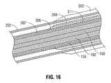
- the assembly 112also includes an inner fluid feed member 206 and an outer fluid feed member 208 as shown in FIGS. 14-16 .
- the fluid feed members 206 and 208have a substantially tubular shape and are formed from a conductive metal, such as copper, stainless steel, tin, and various alloys thereof or may be coated with a conductive material (e.g., metal).
- the fluid feed members 206 and 208are coupled to the connection hub 122 and are configured to circulate fluid through the assembly 112 .
- the fluid feed members 206 and 208includes one or more fluid lumens 207 and 211 , respectively, defined therein which terminate in one or more openings defined in the distal end thereof similar to the fluid feed members 106 and 108 .
- the fluid feed member 206is disposed around the outer conductor 156 and is in electro-mechanical contact therewith.
- the fluid feed member 208is, in turn, disposed about the fluid feed member 208 with the distal end thereof terminating proximally of the distal end of the fluid feed member 206 .
- An outer cooling jacket 222is included in the assembly 12 as shown in FIG. 14 .
- the cooling jacket 222is disposed around the fluid feed member 208 to form a waterproof seal thereabout and extends to the trocar 125 , thereby enclosing the loading 190 . More specifically, the cooling jacket 122 is coupled the base portion 127 or the tapered rim 205 of the trocar 125 such that there is sufficient clearance for the outer jacket 202 to mate with the trocar 125 . Since the cooling jacket 222 is disposed on top of the fluid feed member 208 , the cooling jacket 222 defines a fluid lumen 224 around feedline 120 . The cooling jacket 222 extends to the trocar 125 and may be formed from similar materials as the cooling jackets of assembly 12 .
- the dielectric coolant fluid 35(e.g., saline, deionized water, etc.) is supplied to the assembly 112 by the pump 34 through the connection hub 122 , which is in fluid communication with the fluid feed members 206 and 208 . Similar to the system described above, the fluid 35 flows into the fluid lumen 224 from the fluid feed member 206 thereby contacting the outer conductor 156 and removing heat. Since the outer conductor 156 is sealed by the cast seal 210 , the coolant fluid 35 is not in direct physical contact therewith. The fluid 35 is withdrawn through the fluid feed member 208 , thereby circulating the fluid 35 from the distal end to the proximal end of the feedline 120 . In another embodiment, the fluid 35 flow may be reversed, and the fluid 35 may be supplied through the fluid flow line 208 such that the fluid flows and then suctioned out through the fluid flow line 206 .
- the fluid 35may be reversed, and the fluid 35 may be supplied through the fluid flow line 208 such that the fluid flows and then
- the slidable outer jacket 202is adapted to slide along the cooling jacket 202 and the fluid feed member 208 from a closed configuration in which the slidable outer jacket 202 is mated with the trocar 125 and a retracted configuration in which the slidable outer jacket 202 is disposed a predetermined length alone the assembly 112 (e.g., half wavelength, quarter wavelength, etc.).
- the assembly 112also includes a contact assembly 130 as shown in FIGS. 9-11 to provide electrical contact between the fluid feed members 206 and 208 and the sliding outer jacket 202 .
Landscapes
- Health & Medical Sciences (AREA)
- Surgery (AREA)
- Life Sciences & Earth Sciences (AREA)
- Biomedical Technology (AREA)
- Medical Informatics (AREA)
- Nuclear Medicine, Radiotherapy & Molecular Imaging (AREA)
- Electromagnetism (AREA)
- Engineering & Computer Science (AREA)
- Physics & Mathematics (AREA)
- Heart & Thoracic Surgery (AREA)
- Otolaryngology (AREA)
- Molecular Biology (AREA)
- Animal Behavior & Ethology (AREA)
- General Health & Medical Sciences (AREA)
- Public Health (AREA)
- Veterinary Medicine (AREA)
- Surgical Instruments (AREA)
Abstract
Description
Claims (7)
Priority Applications (8)
| Application Number | Priority Date | Filing Date | Title |
|---|---|---|---|
| US12/129,482US8059059B2 (en) | 2008-05-29 | 2008-05-29 | Slidable choke microwave antenna |
| CA2913728ACA2913728C (en) | 2008-05-29 | 2009-05-27 | Slidable choke microwave antenna |
| CA2666899ACA2666899C (en) | 2008-05-29 | 2009-05-27 | Slidable choke microwave antenna |
| AU2009202106AAU2009202106B2 (en) | 2008-05-29 | 2009-05-28 | Slidable choke microwave antenna |
| JP2009129719AJP5460128B2 (en) | 2008-05-29 | 2009-05-28 | Slideable choke microwave antenna |
| EP09161502.1AEP2128929B1 (en) | 2008-05-29 | 2009-05-29 | Slidable choke microwave antenna |
| EP17183936.8AEP3264528A1 (en) | 2008-05-29 | 2009-05-29 | Slidable choke microwave antenna |
| US13/268,143US8361062B2 (en) | 2008-05-29 | 2011-10-07 | Slidable choke microwave antenna |
Applications Claiming Priority (1)
| Application Number | Priority Date | Filing Date | Title |
|---|---|---|---|
| US12/129,482US8059059B2 (en) | 2008-05-29 | 2008-05-29 | Slidable choke microwave antenna |
Related Child Applications (1)
| Application Number | Title | Priority Date | Filing Date |
|---|---|---|---|
| US13/268,143DivisionUS8361062B2 (en) | 2008-05-29 | 2011-10-07 | Slidable choke microwave antenna |
Publications (2)
| Publication Number | Publication Date |
|---|---|
| US20090295674A1 US20090295674A1 (en) | 2009-12-03 |
| US8059059B2true US8059059B2 (en) | 2011-11-15 |
Family
ID=40973174
Family Applications (2)
| Application Number | Title | Priority Date | Filing Date |
|---|---|---|---|
| US12/129,482Expired - Fee RelatedUS8059059B2 (en) | 2008-05-29 | 2008-05-29 | Slidable choke microwave antenna |
| US13/268,143ActiveUS8361062B2 (en) | 2008-05-29 | 2011-10-07 | Slidable choke microwave antenna |
Family Applications After (1)
| Application Number | Title | Priority Date | Filing Date |
|---|---|---|---|
| US13/268,143ActiveUS8361062B2 (en) | 2008-05-29 | 2011-10-07 | Slidable choke microwave antenna |
Country Status (5)
| Country | Link |
|---|---|
| US (2) | US8059059B2 (en) |
| EP (2) | EP3264528A1 (en) |
| JP (1) | JP5460128B2 (en) |
| AU (1) | AU2009202106B2 (en) |
| CA (2) | CA2913728C (en) |
Cited By (53)
| Publication number | Priority date | Publication date | Assignee | Title |
|---|---|---|---|---|
| US20100073249A1 (en)* | 2008-09-24 | 2010-03-25 | Fujitsu Limited | Aperture antenna |
| US20110034919A1 (en)* | 2009-08-06 | 2011-02-10 | Vivant Medical, Inc. | Vented Positioner and Spacer and Method of Use |
| US20110060326A1 (en)* | 2009-09-09 | 2011-03-10 | Vivant Medical, Inc. | System and Method for Performing an Ablation Procedure |
| US20110098695A1 (en)* | 2009-10-27 | 2011-04-28 | Vivant Medical,Inc. | System and Method for Monitoring Ablation Size |
| US20110098697A1 (en)* | 2009-10-28 | 2011-04-28 | Vivant Medical, Inc. | System and Method for Monitoring Ablation Size |
| US20120029503A1 (en)* | 2008-05-29 | 2012-02-02 | Vivant Medical, Inc. | Slidable Choke Microwave Antenna |
| US20120259329A1 (en)* | 2011-04-08 | 2012-10-11 | Vivant Medical, Inc. | Microwave Ablation Instrument with Interchangeable Antenna Probe |
| US8328800B2 (en) | 2009-08-05 | 2012-12-11 | Vivant Medical, Inc. | Directive window ablation antenna with dielectric loading |
| US8328801B2 (en) | 2009-08-17 | 2012-12-11 | Vivant Medical, Inc. | Surface ablation antenna with dielectric loading |
| US8355803B2 (en) | 2009-09-16 | 2013-01-15 | Vivant Medical, Inc. | Perfused core dielectrically loaded dipole microwave antenna probe |
| US8608731B2 (en) | 2009-02-20 | 2013-12-17 | Covidien Lp | Leaky-wave antennas for medical applications |
| US8667674B2 (en) | 2008-06-09 | 2014-03-11 | Covidien Lp | Surface ablation process with electrode cooling methods |
| US8679108B2 (en) | 2009-02-20 | 2014-03-25 | Covidien Lp | Leaky-wave antennas for medical applications |
| US8690869B2 (en) | 2009-06-02 | 2014-04-08 | Covidien Lp | Electrosurgical devices with directional radiation pattern |
| US8745854B2 (en) | 2009-09-09 | 2014-06-10 | Covidien Lp | Method for constructing a dipole antenna |
| US8894640B2 (en) | 2009-09-24 | 2014-11-25 | Covidien Lp | Optical detection of interrupted fluid flow to ablation probe |
| US8906008B2 (en) | 2012-05-22 | 2014-12-09 | Covidien Lp | Electrosurgical instrument |
| US8968291B2 (en) | 2007-11-16 | 2015-03-03 | Covidien Lp | Dynamically matched microwave antenna for tissue ablation |
| US9017328B2 (en) | 2008-01-29 | 2015-04-28 | Covidien Lp | Polyp encapsulation system and method |
| US20150250540A1 (en)* | 2014-03-10 | 2015-09-10 | Wisconsin Alumni Research Foundation | Microwave ablation antenna system |
| US9192439B2 (en) | 2012-06-29 | 2015-11-24 | Covidien Lp | Method of manufacturing a surgical instrument |
| US9192440B2 (en) | 2010-02-05 | 2015-11-24 | Covidien Lp | Electrosurgical devices with choke shorted to biological tissue |
| US9192437B2 (en) | 2009-05-27 | 2015-11-24 | Covidien Lp | Narrow gauge high strength choked wet tip microwave ablation antenna |
| US9254172B2 (en) | 2008-09-03 | 2016-02-09 | Covidien Lp | Shielding for an isolation apparatus used in a microwave generator |
| US9375278B2 (en) | 2009-09-18 | 2016-06-28 | Covidien Lp | Tissue ablation system with energy distribution |
| US20170077609A1 (en)* | 2014-05-05 | 2017-03-16 | Per Olov Risman | Microwave antenna applicator |
| US9681916B2 (en) | 2012-01-06 | 2017-06-20 | Covidien Lp | System and method for treating tissue using an expandable antenna |
| US9693823B2 (en) | 2012-01-06 | 2017-07-04 | Covidien Lp | System and method for treating tissue using an expandable antenna |
| US9833286B2 (en) | 2009-05-06 | 2017-12-05 | Covidien Lp | Power-stage antenna integrated system with high-strength shaft |
| US9861440B2 (en) | 2010-05-03 | 2018-01-09 | Neuwave Medical, Inc. | Energy delivery systems and uses thereof |
| US9867670B2 (en) | 2009-04-01 | 2018-01-16 | Covidien Lp | Microwave ablation system and user-controlled ablation size and method of use |
| US9877783B2 (en) | 2009-07-28 | 2018-01-30 | Neuwave Medical, Inc. | Energy delivery systems and uses thereof |
| US9888956B2 (en) | 2013-01-22 | 2018-02-13 | Angiodynamics, Inc. | Integrated pump and generator device and method of use |
| US9901398B2 (en) | 2012-06-29 | 2018-02-27 | Covidien Lp | Microwave antenna probes |
| US9949794B2 (en) | 2008-03-27 | 2018-04-24 | Covidien Lp | Microwave ablation devices including expandable antennas and methods of use |
| US10022186B2 (en) | 2008-08-28 | 2018-07-17 | Covidien Lp | Microwave antenna with cooled handle |
| US10213256B2 (en) | 2009-10-28 | 2019-02-26 | Covidien Lp | System and method for monitoring ablation size |
| US10321962B2 (en) | 2007-11-01 | 2019-06-18 | Covidien Lp | Method for volume determination and geometric reconstruction |
| US10363092B2 (en) | 2006-03-24 | 2019-07-30 | Neuwave Medical, Inc. | Transmission line with heat transfer ability |
| US10376314B2 (en) | 2006-07-14 | 2019-08-13 | Neuwave Medical, Inc. | Energy delivery systems and uses thereof |
| US10390882B2 (en) | 2009-09-29 | 2019-08-27 | Covidien Lp | Flow rate monitor for fluid cooled microwave ablation probe |
| WO2019204407A1 (en) | 2018-04-18 | 2019-10-24 | Boston Scientific Scimed, Inc. | Microwave tissue ablation probe with non-metallic introducer set |
| US10531917B2 (en) | 2016-04-15 | 2020-01-14 | Neuwave Medical, Inc. | Systems and methods for energy delivery |
| US10660691B2 (en) | 2015-10-07 | 2020-05-26 | Angiodynamics, Inc. | Multiple use subassembly with integrated fluid delivery system for use with single or dual-lumen peristaltic tubing |
| US10667860B2 (en) | 2011-12-21 | 2020-06-02 | Neuwave Medical, Inc. | Energy delivery systems and uses thereof |
| US10675089B2 (en) | 2009-09-29 | 2020-06-09 | Covidien Lp | Management of voltage standing wave ratio at skin surface during microwave ablation |
| US10707581B2 (en) | 2018-01-03 | 2020-07-07 | Wisconsin Alumni Research Foundation | Dipole antenna for microwave ablation |
| US10952792B2 (en) | 2015-10-26 | 2021-03-23 | Neuwave Medical, Inc. | Energy delivery systems and uses thereof |
| US11389235B2 (en) | 2006-07-14 | 2022-07-19 | Neuwave Medical, Inc. | Energy delivery systems and uses thereof |
| US11672596B2 (en) | 2018-02-26 | 2023-06-13 | Neuwave Medical, Inc. | Energy delivery devices with flexible and adjustable tips |
| US11832879B2 (en) | 2019-03-08 | 2023-12-05 | Neuwave Medical, Inc. | Systems and methods for energy delivery |
| US12318133B2 (en) | 2008-01-23 | 2025-06-03 | Covidien Lp | Choked microwave antenna |
| USD1084316S1 (en) | 2023-11-20 | 2025-07-15 | Angiodynamics, Inc. | Ferrule |
Families Citing this family (34)
| Publication number | Priority date | Publication date | Assignee | Title |
|---|---|---|---|---|
| US9113924B2 (en) | 2008-10-17 | 2015-08-25 | Covidien Lp | Choked dielectric loaded tip dipole microwave antenna |
| USD634010S1 (en) | 2009-08-05 | 2011-03-08 | Vivant Medical, Inc. | Medical device indicator guide |
| GB2474233A (en) | 2009-10-06 | 2011-04-13 | Uk Investments Associates Llc | Cooling pump comprising a detachable head portion |
| CN102652144B (en) | 2009-12-10 | 2014-12-10 | 东曹株式会社 | Vinyl chloride resin latex, process for producing same, and thermal transfer image-receiving sheet obtained using same |
| US8409188B2 (en)* | 2010-03-26 | 2013-04-02 | Covidien Lp | Ablation devices with adjustable radiating section lengths, electrosurgical systems including same, and methods of adjusting ablation fields using same |
| US9561076B2 (en) | 2010-05-11 | 2017-02-07 | Covidien Lp | Electrosurgical devices with balun structure for air exposure of antenna radiating section and method of directing energy to tissue using same |
| US8740893B2 (en) | 2010-06-30 | 2014-06-03 | Covidien Lp | Adjustable tuning of a dielectrically loaded loop antenna |
| USD673685S1 (en) | 2010-09-08 | 2013-01-01 | Vivant Medical, Inc. | Microwave device spacer and positioner with arcuate slot |
| US8945144B2 (en) | 2010-09-08 | 2015-02-03 | Covidien Lp | Microwave spacers and method of use |
| US8968289B2 (en) | 2010-10-22 | 2015-03-03 | Covidien Lp | Microwave spacers and methods of use |
| US9119647B2 (en)* | 2010-11-12 | 2015-09-01 | Covidien Lp | Apparatus, system and method for performing an electrosurgical procedure |
| US9770294B2 (en) | 2011-01-05 | 2017-09-26 | Covidien Lp | Energy-delivery devices with flexible fluid-cooled shaft, inflow/outflow junctions suitable for use with same, and systems including same |
| US8932281B2 (en)* | 2011-01-05 | 2015-01-13 | Covidien Lp | Energy-delivery devices with flexible fluid-cooled shaft, inflow/outflow junctions suitable for use with same, and systems including same |
| US9011421B2 (en)* | 2011-01-05 | 2015-04-21 | Covidien Lp | Energy-delivery devices with flexible fluid-cooled shaft, inflow/outflow junctions suitable for use with same, and systems including same |
| US9017319B2 (en)* | 2011-01-05 | 2015-04-28 | Covidien Lp | Energy-delivery devices with flexible fluid-cooled shaft, inflow/outflow junctions suitable for use with same, and systems including same |
| US8992413B2 (en)* | 2011-05-31 | 2015-03-31 | Covidien Lp | Modified wet tip antenna design |
| US8888771B2 (en) | 2011-07-15 | 2014-11-18 | Covidien Lp | Clip-over disposable assembly for use with hemostat-style surgical instrument and methods of manufacturing same |
| US9113930B2 (en) | 2012-01-05 | 2015-08-25 | Covidien Lp | Ablation systems, probes, and methods for reducing radiation from an ablation probe into the environment |
| US9375274B2 (en)* | 2012-01-05 | 2016-06-28 | Covidien Lp | Ablation systems, probes, and methods for reducing radiation from an ablation probe into the environment |
| EP2647971A1 (en)* | 2012-04-04 | 2013-10-09 | VEGA Grieshaber KG | Fill level measuring device and adapter with reflector |
| US9301723B2 (en)* | 2013-03-15 | 2016-04-05 | Covidien Lp | Microwave energy-delivery device and system |
| GB201312416D0 (en) | 2013-07-11 | 2013-08-28 | Creo Medical Ltd | Electrosurgical Device |
| CN104323856B (en)* | 2014-11-11 | 2017-07-18 | 南京维京九洲医疗器械研发中心 | Without magnetic water-cooled microwave ablation needle manufacture method |
| US11039884B2 (en) | 2015-06-12 | 2021-06-22 | The University Of Sydney | Microwave ablation device |
| US10813692B2 (en)* | 2016-02-29 | 2020-10-27 | Covidien Lp | 90-degree interlocking geometry for introducer for facilitating deployment of microwave radiating catheter |
| RU2665621C2 (en)* | 2016-11-30 | 2018-09-03 | Борис Лазаревич Ихлов | Non-invasive method for tumor tissues growth inhibition and necrosis thereof |
| CN107260301B (en)* | 2017-04-20 | 2021-04-02 | 南通融锋医疗科技有限公司 | True circle microwave ablation antenna and system |
| GB2562290B (en)* | 2017-05-11 | 2023-04-05 | Gyrus Medical Ltd | Microwave ablation antenna assemblies |
| GB2575485A (en)* | 2018-07-12 | 2020-01-15 | Creo Medical Ltd | Electrosurgical instrument |
| US11382682B2 (en) | 2018-11-28 | 2022-07-12 | Boston Scientific Scimed, Inc. | Closed irrigated radiofrequency bipolar tined ablation probe |
| US11957409B2 (en)* | 2018-12-19 | 2024-04-16 | Boston Scientific Scimed, Inc. | Irrigation cooling structure for microwave ablation tissue probe |
| US12262976B2 (en) | 2019-03-13 | 2025-04-01 | Blossom Innovations Llc | Devices, systems and methods for tissue analysis, location determination and therapy thereof using optical radiation |
| US11191446B2 (en)* | 2019-11-27 | 2021-12-07 | Blossom Innovations, LLC | Devices, systems and methods for tissue analysis, locaton determination and tissue ablation |
| CN113193388B (en)* | 2021-04-15 | 2023-06-16 | 维沃移动通信有限公司 | Electronic equipment |
Citations (158)
| Publication number | Priority date | Publication date | Assignee | Title |
|---|---|---|---|---|
| DE390937C (en) | 1922-10-13 | 1924-03-03 | Adolf Erb | Device for internal heating of furnace furnaces for hardening, tempering, annealing, quenching and melting |
| DE1099658B (en) | 1959-04-29 | 1961-02-16 | Siemens Reiniger Werke Ag | Automatic switch-on device for high-frequency surgical devices |
| FR1275415A (en) | 1960-09-26 | 1961-11-10 | Device for detecting disturbances for electrical installations, in particular electrosurgery | |
| DE1139927B (en) | 1961-01-03 | 1962-11-22 | Friedrich Laber | High-frequency surgical device |
| FR1347865A (en) | 1962-11-22 | 1964-01-04 | Improvements to diathermo-coagulation devices | |
| US3230957A (en) | 1960-03-23 | 1966-01-25 | Philips Corp | High frequency therapeutic apparatus |
| DE1439302A1 (en) | 1963-10-26 | 1969-01-23 | Siemens Ag | High-frequency surgical device |
| US3631363A (en) | 1969-11-14 | 1971-12-28 | Gen Electric | High-frequency cavity oscillator having improved tuning means |
| SU401367A1 (en) | 1971-10-05 | 1973-10-12 | Тернопольский государственный медицинский институт | BIAKTIVNYE ELECTRO SURGICAL INSTRUMENT |
| DE2455174A1 (en) | 1973-11-21 | 1975-05-22 | Termiflex Corp | INPUT / OUTPUT DEVICE FOR DATA EXCHANGE WITH DATA PROCESSING DEVICES |
| DE2415263A1 (en) | 1974-03-29 | 1975-10-02 | Aesculap Werke Ag | Surgical H.F. coagulation probe has electrode tongs - with exposed ends of insulated conductors forming tong-jaws |
| FR2235669B1 (en) | 1973-07-07 | 1976-05-07 | Lunacek Boris | |
| DE2460481A1 (en) | 1974-12-20 | 1976-06-24 | Delma Elektro Med App | Electrode grip for remote HF surgical instrument switching - has shaped insulated piece with contact ring of sterilizable (silicon) rubber |
| DE2627679A1 (en) | 1975-06-26 | 1977-01-13 | Marcel Lamidey | HEMATISTIC HIGH FREQUENCY EXTRACTOR FORCEPS |
| FR2276027B3 (en) | 1974-06-25 | 1977-05-06 | Medical Plastics Inc | |
| DE1149832C2 (en) | 1961-02-25 | 1977-10-13 | Siemens AG, 1000 Berlin und 8000 München | HIGH FREQUENCY SURGICAL EQUIPMENT |
| DE2823291A1 (en) | 1978-05-27 | 1979-11-29 | Rainer Ing Grad Koch | Coagulation instrument automatic HF switching circuit - has first lead to potentiometer and second to transistor base |
| SU727201A2 (en) | 1977-11-02 | 1980-04-15 | Киевский Научно-Исследовательский Институт Нейрохирургии | Electric surgical apparatus |
| DE2439587C3 (en) | 1973-08-23 | 1980-04-30 | Matburn (Holdings) Ltd., London | Electrosurgery device |
| FR2313708B1 (en) | 1975-06-02 | 1980-07-04 | Sybron Corp | |
| DE2504280C3 (en) | 1975-02-01 | 1980-08-28 | Hans Heinrich Prof. Dr. 8035 Gauting Meinke | Device for cutting and / or coagulating human tissue with high frequency current |
| DE2803275C3 (en) | 1978-01-26 | 1980-09-25 | Aesculap-Werke Ag Vormals Jetter & Scheerer, 7200 Tuttlingen | Remote switching device for switching a monopolar HF surgical device |
| DE2407559C3 (en) | 1974-02-16 | 1982-01-21 | Dornier System Gmbh, 7990 Friedrichshafen | Heat probe |
| DE3045996A1 (en) | 1980-12-05 | 1982-07-08 | Medic Eschmann Handelsgesellschaft für medizinische Instrumente mbH, 2000 Hamburg | Electro-surgical scalpel instrument - has power supply remotely controlled by surgeon |
| DE2540968C2 (en) | 1975-09-13 | 1982-12-30 | Erbe Elektromedizin GmbH, 7400 Tübingen | Device for switching on the coagulation current of a bipolar coagulation forceps |
| DE2602517C3 (en) | 1975-01-23 | 1983-01-13 | Dentsply International Inc., 17404 York, Pa. | Device for monitoring the current return conductor in an electrosurgical HF device |
| FR2517953A1 (en) | 1981-12-10 | 1983-06-17 | Alvar Electronic | Diaphanometer for optical examination of breast tissue structure - measures tissue transparency using two plates and optical fibre bundle cooperating with photoelectric cells |
| DE2429021C2 (en) | 1974-06-18 | 1983-12-08 | Erbe Elektromedizin GmbH, 7400 Tübingen | Remote switching device for an HF surgical device |
| DE3143421C2 (en) | 1980-11-04 | 1985-05-02 | The Agency Of Industrial Science And Technology, Tokio/Tokyo | Laser scalpel |
| FR2502935B1 (en) | 1981-03-31 | 1985-10-04 | Dolley Roger | METHOD AND DEVICE FOR CONTROLLING THE COAGULATION OF TISSUES USING A HIGH FREQUENCY CURRENT |
| US4557272A (en) | 1980-03-31 | 1985-12-10 | Microwave Associates, Inc. | Microwave endoscope detection and treatment system |
| US4612940A (en) | 1984-05-09 | 1986-09-23 | Scd Incorporated | Microwave dipole probe for in vivo localized hyperthermia |
| US4643186A (en) | 1985-10-30 | 1987-02-17 | Rca Corporation | Percutaneous transluminal microwave catheter angioplasty |
| US4658836A (en) | 1985-06-28 | 1987-04-21 | Bsd Medical Corporation | Body passage insertable applicator apparatus for electromagnetic |
| FR2573301B3 (en) | 1984-11-16 | 1987-04-30 | Lamidey Gilles | SURGICAL PLIERS AND ITS CONTROL AND CONTROL APPARATUS |
| US4674481A (en) | 1983-10-31 | 1987-06-23 | Board Of Regents, The University Of Texas System | RF electromagnetic field generation apparatus for regionally-focused hyperthermia |
| DE2946728C2 (en) | 1979-11-20 | 1987-07-30 | Erbe Elektromedizin Gmbh, 7400 Tuebingen, De | |
| DE3120102C2 (en) | 1981-05-20 | 1987-08-20 | Fischer Met Gmbh, 7800 Freiburg, De | |
| US4700716A (en) | 1986-02-27 | 1987-10-20 | Kasevich Associates, Inc. | Collinear antenna array applicator |
| EP0246350A1 (en) | 1986-05-23 | 1987-11-25 | Erbe Elektromedizin GmbH. | Coagulation electrode |
| DE8712328U1 (en) | 1987-09-11 | 1988-02-18 | Jakoubek, Franz, 7201 Emmingen-Liptingen | Endoscopy forceps |
| US4743725A (en) | 1985-12-05 | 1988-05-10 | Skandinavisk Torkteknik Ab | Coaxial line microwave heating applicator with asymmetrical radiation pattern |
| DE3711511C1 (en) | 1987-04-04 | 1988-06-30 | Hartmann & Braun Ag | Method for determining gas concentrations in a gas mixture and sensor for measuring thermal conductivity |
| DE3510586C2 (en) | 1985-03-23 | 1988-07-28 | Erbe Elektromedizin Gmbh, 7400 Tuebingen, De | |
| US4798215A (en) | 1984-03-15 | 1989-01-17 | Bsd Medical Corporation | Hyperthermia apparatus |
| US4800899A (en) | 1984-10-22 | 1989-01-31 | Microthermia Technology, Inc. | Apparatus for destroying cells in tumors and the like |
| US4807620A (en) | 1987-05-22 | 1989-02-28 | Advanced Interventional Systems, Inc. | Apparatus for thermal angioplasty |
| US4817635A (en) | 1987-03-23 | 1989-04-04 | Duke University | Interstitial applicator with cancellation/enhancement gap |
| US4825880A (en) | 1987-06-19 | 1989-05-02 | The Regents Of The University Of California | Implantable helical coil microwave antenna |
| US4841988A (en) | 1987-10-15 | 1989-06-27 | Marquette Electronics, Inc. | Microwave hyperthermia probe |
| DE2820908C2 (en) | 1977-05-16 | 1989-11-16 | Joseph Coubron Fr Skovajsa | |
| US4934365A (en) | 1988-06-30 | 1990-06-19 | Massachusetts Institute Of Technology | Non-invasive hyperthermia method and apparatus |
| US4945912A (en) | 1988-11-25 | 1990-08-07 | Sensor Electronics, Inc. | Catheter with radiofrequency heating applicator |
| US5026959A (en) | 1988-11-16 | 1991-06-25 | Tokyo Keiki Co. Ltd. | Microwave radiator for warming therapy |
| US5057106A (en) | 1986-02-27 | 1991-10-15 | Kasevich Associates, Inc. | Microwave balloon angioplasty |
| US5065819A (en) | 1990-03-09 | 1991-11-19 | Kai Technologies | Electromagnetic apparatus and method for in situ heating and recovery of organic and inorganic materials |
| US5097845A (en) | 1987-10-15 | 1992-03-24 | Labthermics Technologies | Microwave hyperthermia probe |
| US5097846A (en) | 1986-12-15 | 1992-03-24 | Larsen Lawrence E | Apparatus for diathermy treatment and control |
| US5129396A (en) | 1988-11-10 | 1992-07-14 | Arye Rosen | Microwave aided balloon angioplasty with lumen measurement |
| DE4238263A1 (en) | 1991-11-15 | 1993-05-19 | Minnesota Mining & Mfg | Adhesive comprising hydrogel and crosslinked polyvinyl:lactam - is used in electrodes for biomedical application providing low impedance and good mechanical properties when water and/or moisture is absorbed from skin |
| EP0521264A3 (en) | 1991-07-03 | 1993-06-16 | W.L. Gore & Associates Gmbh | Antenna device with feed |
| EP0556705A1 (en) | 1992-02-20 | 1993-08-25 | DELMA ELEKTRO-UND MEDIZINISCHE APPARATEBAU GESELLSCHAFT mbH | High frequency surgery device |
| EP0558429A1 (en) | 1992-02-26 | 1993-09-01 | PECHINEY RECHERCHE (Groupement d'Intérêt Economique géré par l'ordonnance no. 67-821 du 23 Septembre 1967) | Method of simultaneous measuring of electrical resistivety and thermal conductivity |
| US5281217A (en) | 1992-04-13 | 1994-01-25 | Ep Technologies, Inc. | Steerable antenna systems for cardiac ablation that minimize tissue damage and blood coagulation due to conductive heating patterns |
| US5300068A (en) | 1992-04-21 | 1994-04-05 | St. Jude Medical, Inc. | Electrosurgical apparatus |
| US5301687A (en) | 1991-06-06 | 1994-04-12 | Trustees Of Dartmouth College | Microwave applicator for transurethral hyperthermia |
| US5330518A (en) | 1992-03-06 | 1994-07-19 | Urologix, Inc. | Method for treating interstitial tissue associated with microwave thermal therapy |
| US5358515A (en) | 1989-08-16 | 1994-10-25 | Deutsches Krebsforschungzentrum Stiftung Des Offentlichen Rechts | Microwave hyperthermia applicator |
| US5369251A (en) | 1992-09-14 | 1994-11-29 | Kdc Technology Corp. | Microwave interstitial hyperthermia probe |
| DE4303882C2 (en) | 1993-02-10 | 1995-02-09 | Kernforschungsz Karlsruhe | Combination instrument for separation and coagulation for minimally invasive surgery |
| US5405346A (en) | 1993-05-14 | 1995-04-11 | Fidus Medical Technology Corporation | Tunable microwave ablation catheter |
| DE3604823C2 (en) | 1986-02-15 | 1995-06-01 | Lindenmeier Heinz | High frequency generator with automatic power control for high frequency surgery |
| US5549639A (en) | 1994-09-16 | 1996-08-27 | Sandia Corporation | Non-invasive hyperthermia apparatus including coaxial applicator having a non-invasive radiometric receiving antenna incorporated therein and method of use thereof |
| GB2295094B (en) | 1993-07-27 | 1996-10-30 | Microsulis Ltd | Probe for applying microwave radiation |
| DE29616210U1 (en) | 1996-09-18 | 1996-11-14 | Olympus Winter & Ibe Gmbh, 22045 Hamburg | Handle for surgical instruments |
| DE19608716C1 (en) | 1996-03-06 | 1997-04-17 | Aesculap Ag | Bipolar surgical holding instrument |
| US5658278A (en) | 1992-12-01 | 1997-08-19 | Cardiac Pathways, Inc. | Catheter for RF ablation with cooled electrode and method |
| DE3904558C2 (en) | 1989-02-15 | 1997-09-18 | Lindenmeier Heinz | Automatically power-controlled high-frequency generator for high-frequency surgery |
| DE19751106A1 (en) | 1996-11-27 | 1998-05-28 | Eastman Kodak Co | Laser printer with array of laser diodes |
| US5776176A (en) | 1996-06-17 | 1998-07-07 | Urologix Inc. | Microwave antenna for arterial for arterial microwave applicator |
| DE19717411A1 (en) | 1997-04-25 | 1998-11-05 | Aesculap Ag & Co Kg | Monitoring of thermal loading of patient tissue in contact region of neutral electrode of HF treatment unit |
| DE3942998C2 (en) | 1989-12-27 | 1998-11-26 | Delma Elektro Med App | High frequency electrosurgical unit |
| US5861021A (en) | 1996-06-17 | 1999-01-19 | Urologix Inc | Microwave thermal therapy of cardiac tissue |
| US5871523A (en) | 1993-10-15 | 1999-02-16 | Ep Technologies, Inc. | Helically wound radio-frequency emitting electrodes for creating lesions in body tissue |
| US5871525A (en) | 1992-04-13 | 1999-02-16 | Ep Technologies, Inc. | Steerable ablation catheter system |
| US5904709A (en) | 1996-04-17 | 1999-05-18 | The United States Of America As Represented By The Administrator Of The National Aeronautics And Space Administration | Microwave treatment for cardiac arrhythmias |
| DE19751108A1 (en) | 1997-11-18 | 1999-05-20 | Beger Frank Michael Dipl Desig | Electrosurgical operation tool, especially for diathermy |
| DE19801173C1 (en) | 1998-01-15 | 1999-07-15 | Kendall Med Erzeugnisse Gmbh | Clamp connector for film electrodes |
| US5938692A (en) | 1996-03-26 | 1999-08-17 | Urologix, Inc. | Voltage controlled variable tuning antenna |
| US5944749A (en) | 1996-10-04 | 1999-08-31 | Titan Corporation | X-ray needle providing heating with microwave energy |
| US5957969A (en) | 1993-05-14 | 1999-09-28 | Fidus Medical Technology Corporation | Tunable microwave ablation catheter system and method |
| US5957922A (en) | 1993-06-10 | 1999-09-28 | Vidamed, Inc. | Transurethral radio frequency apparatus for ablation of the prostate gland and method |
| US5964755A (en) | 1994-06-24 | 1999-10-12 | Vioacare International, Inc. | Thin layer ablation apparatus |
| EP0836868A3 (en) | 1996-10-18 | 1999-11-24 | Gebr. Berchtold GmbH & Co. | High frequency surgical apparatus and method for operating same |
| US6016452A (en) | 1996-03-19 | 2000-01-18 | Kasevich; Raymond S. | Dynamic heating method and radio frequency thermal treatment |
| US6019757A (en) | 1995-07-07 | 2000-02-01 | Target Therapeutics, Inc. | Endoluminal electro-occlusion detection apparatus and method |
| DE19848540A1 (en) | 1998-10-21 | 2000-05-25 | Reinhard Kalfhaus | Circuit layout and method for operating a single- or multiphase current inverter connects an AC voltage output to a primary winding and current and a working resistance to a transformer's secondary winding and current. |
| EP1055400A1 (en) | 1999-05-28 | 2000-11-29 | Gyrus Medical Limited | An electrosurgical instrument |
| JP2000342599A (en) | 1999-05-21 | 2000-12-12 | Gyrus Medical Ltd | Generator for electrosurgical operation, electrosurgical operation system, method for operating this system and method for performing amputation and resection of tissue by electrosurgical operation |
| JP2000350732A (en) | 1999-05-21 | 2000-12-19 | Gyrus Medical Ltd | Electrosurgical system, generator for electrosurgery, and method for cutting or excising tissue by electrosurgery |
| JP2001008944A (en) | 1999-05-28 | 2001-01-16 | Gyrus Medical Ltd | Electric surgical signal generator and electric surgical system |
| JP2001029356A (en) | 1999-06-11 | 2001-02-06 | Gyrus Medical Ltd | Electric and surgical signal generator |
| US6210367B1 (en) | 1995-09-06 | 2001-04-03 | Microwave Medical Systems, Inc. | Intracorporeal microwave warming method and apparatus |
| US6245062B1 (en) | 1998-10-23 | 2001-06-12 | Afx, Inc. | Directional reflector shield assembly for a microwave ablation instrument |
| DE4339049C2 (en) | 1993-11-16 | 2001-06-28 | Erbe Elektromedizin | Surgical system configuration facility |
| US6287302B1 (en) | 1999-06-14 | 2001-09-11 | Fidus Medical Technology Corporation | End-firing microwave ablation instrument with horn reflection device |
| US6289249B1 (en) | 1996-04-17 | 2001-09-11 | The United States Of America As Represented By The Administrator Of The National Aeronautics And Space Administration | Transcatheter microwave antenna |
| US6312428B1 (en) | 1995-03-03 | 2001-11-06 | Neothermia Corporation | Methods and apparatus for therapeutic cauterization of predetermined volumes of biological tissue |
| US6325796B1 (en) | 1999-05-04 | 2001-12-04 | Afx, Inc. | Microwave ablation instrument with insertion probe |
| US20020022836A1 (en) | 1999-03-05 | 2002-02-21 | Gyrus Medical Limited | Electrosurgery system |
| US6398781B1 (en) | 1999-03-05 | 2002-06-04 | Gyrus Medical Limited | Electrosurgery system |
| US6440158B1 (en) | 1990-05-11 | 2002-08-27 | Mark A. Saab | Heat transfer catheter apparatus and method of making and using same |
| US6485486B1 (en) | 1997-08-05 | 2002-11-26 | Trustees Of Dartmouth College | System and methods for fallopian tube occlusion |
| US6496738B2 (en) | 1995-09-06 | 2002-12-17 | Kenneth L. Carr | Dual frequency microwave heating apparatus |
| EP1159926A3 (en) | 2000-06-03 | 2003-03-19 | Aesculap Ag | Scissor- or forceps-like surgical instrument |
| US20030088242A1 (en)* | 2001-11-02 | 2003-05-08 | Mani Prakash | High-strength microwave antenna assemblies |
| US6582427B1 (en) | 1999-03-05 | 2003-06-24 | Gyrus Medical Limited | Electrosurgery system |
| GB2388039B (en) | 1999-02-25 | 2003-12-17 | Microsulis Ltd | Radiation applicator |
| DE10224154A1 (en) | 2002-05-27 | 2003-12-18 | Celon Ag Medical Instruments | Application device for electrosurgical device for body tissue removal via of HF current has electrode subset selected from active electrode set in dependence on measured impedance of body tissue |
| US6706040B2 (en) | 2001-11-23 | 2004-03-16 | Medlennium Technologies, Inc. | Invasive therapeutic probe |
| GB2387544B (en) | 2002-10-10 | 2004-03-17 | Microsulis Plc | Microwave applicator |
| US6823218B2 (en) | 1999-05-28 | 2004-11-23 | Afx, Inc. | Monopole tip for ablation catheter and methods for using same |
| US20040254621A1 (en) | 1997-09-11 | 2004-12-16 | Jones Christopher S. | Expandable catheter having two sets of electrodes, and method of use |
| US20050015081A1 (en)* | 2003-07-18 | 2005-01-20 | Roman Turovskiy | Devices and methods for cooling microwave antennas |
| DE10328514B3 (en) | 2003-06-20 | 2005-03-03 | Aesculap Ag & Co. Kg | Endoscopic surgical scissor instrument has internal pushrod terminating at distal end in transverse cylindrical head |
| GB2390545B (en) | 2002-07-09 | 2005-04-20 | Barts & London Nhs Trust | Hollow organ probe |
| US20050113893A1 (en) | 1992-08-13 | 2005-05-26 | Radiant Medical, Inc. | Heat transfer catheters and methods of making and using same |
| US6957108B2 (en) | 2003-06-02 | 2005-10-18 | Bsd Medical Corporation | Invasive microwave antenna array for hyperthermia and brachytherapy |
| US6962586B2 (en) | 1999-05-04 | 2005-11-08 | Afx, Inc. | Microwave ablation instrument with insertion probe |
| GB2416307A (en) | 2004-07-16 | 2006-01-25 | Microsulis Ltd | Microwave applicator head with null forming conductors allowing for sensor placement |
| DE202005015147U1 (en) | 2005-09-26 | 2006-02-09 | Health & Life Co., Ltd., Chung-Ho | Biosensor test strip with identifying function for biological measuring instruments has functioning electrode and counter electrode, identification zones with coating of electrically conductive material and reaction zone |
| US20060085054A1 (en) | 2004-09-09 | 2006-04-20 | Zikorus Arthur W | Methods and apparatus for treatment of hollow anatomical structures |
| DE102004022206B4 (en) | 2004-05-04 | 2006-05-11 | Bundesrepublik Deutschland, vertr. d. d. Bundesministerium für Wirtschaft und Arbeit, dieses vertr. d. d. Präsidenten der Physikalisch-Technischen Bundesanstalt | Sensor for measuring thermal conductivity comprises a strip composed of two parallel sections, and two outer heating strips |
| FR2862813B1 (en) | 2003-11-20 | 2006-06-02 | Pellenc Sa | METHOD FOR BALANCED LOADING OF LITHIUM-ION OR POLYMER LITHIUM BATTERY |
| US7101369B2 (en) | 2004-04-29 | 2006-09-05 | Wisconsin Alumni Research Foundation | Triaxial antenna for microwave tissue ablation |
| US7113832B2 (en) | 2001-01-31 | 2006-09-26 | Cnr Consiglio Nazionale Deile Ricerche | Interstitial microwave antenna with miniaturized choke hyperthermia in medicine and surgery |
| US20060241576A1 (en) | 2002-01-15 | 2006-10-26 | Diederich Chris J | System and method providing directional ultrasound therapy to skeletal joints |
| US7128739B2 (en) | 2001-11-02 | 2006-10-31 | Vivant Medical, Inc. | High-strength microwave antenna assemblies and methods of use |
| US20060259024A1 (en) | 2005-05-10 | 2006-11-16 | Roman Turovskiy | Reinforced high strength microwave antenna |
| US20060287649A1 (en) | 1998-12-14 | 2006-12-21 | Ormsby Theodore C | Radio-frequency based catheter system and method for ablating biological tissues |
| US20060289528A1 (en) | 2003-03-26 | 2006-12-28 | Heng-Mao Chiu | Microwave antenna for medical ablation |
| US20070016181A1 (en) | 2004-04-29 | 2007-01-18 | Van Der Weide Daniel W | Microwave tissue resection tool |
| US7180307B2 (en) | 2003-07-28 | 2007-02-20 | Murata Manufacturing Co., Ltd. | Coaxial probe |
| US20070043346A1 (en) | 2003-06-23 | 2007-02-22 | Nigel Cronin | Radiation applicator for microwave medical treatment |
| GB2415630C (en) | 2004-07-02 | 2007-02-27 | Microsulis Ltd | Radiation applicator and method of radiating tissue |
| US20070049917A1 (en) | 2005-08-23 | 2007-03-01 | Deshan Yang | Floating sleeve microwave antenna for tumor ablation |
| US20070060989A1 (en) | 2005-09-07 | 2007-03-15 | Deem Mark E | Apparatus and method for disrupting subcutaneous structures |
| US7244254B2 (en) | 2004-04-29 | 2007-07-17 | Micrablate | Air-core microwave ablation antennas |
| US20070185554A1 (en) | 2006-02-07 | 2007-08-09 | Angiodynamics, Inc. | Interstitial microwave system and method for thermal treatment of diseases |
| US20070203551A1 (en) | 2005-07-01 | 2007-08-30 | Microsulis Limited | Radiation applicator and method of radiating tissue |
| US20070233057A1 (en) | 2006-04-04 | 2007-10-04 | Namiki Seimitsu Houseki Kabushiki Kaisha | Radio frequency medical treatment device and system and usage method thereof |
| US20070282319A1 (en) | 2006-03-24 | 2007-12-06 | Micrablate, Inc. | Center fed dipole for use with tissue ablation systems, devices and methods |
| US20070288079A1 (en) | 2006-03-24 | 2007-12-13 | Micrablate | Energy delivery system and uses thereof |
| US7378363B2 (en) | 2005-05-20 | 2008-05-27 | Skyworks Solutions, Inc. | Dielectric ceramic composition having wide sintering temperature range and reduced exaggerated grain growth |
| US7396355B2 (en) | 1997-09-11 | 2008-07-08 | Vnus Medical Technologies, Inc. | Method and apparatus for applying energy to biological tissue including the use of tumescent tissue compression |
| US20090131926A1 (en)* | 2007-11-16 | 2009-05-21 | Tyco Healthcare Group Lp | Dynamically Matched Microwave Antenna for Tissue Ablation |
| US20090248006A1 (en)* | 2008-03-31 | 2009-10-01 | Paulus Joseph A | Re-Hydration Antenna for Ablation |
| FR2864439B1 (en) | 2003-12-30 | 2010-12-03 | Image Guided Therapy | DEVICE FOR TREATING A VOLUME OF BIOLOGICAL TISSUE BY LOCALIZED HYPERTHERMIA |
Family Cites Families (5)
| Publication number | Priority date | Publication date | Assignee | Title |
|---|---|---|---|---|
| JPS5676962A (en)* | 1979-11-30 | 1981-06-24 | Aloka Co Ltd | Microwave cancer treatment device |
| US5683384A (en)* | 1993-11-08 | 1997-11-04 | Zomed | Multiple antenna ablation apparatus |
| JP2005502417A (en)* | 2001-09-19 | 2005-01-27 | ウロロジックス, インコーポレイテッド | Microwave ablation device |
| US8068921B2 (en)* | 2006-09-29 | 2011-11-29 | Vivant Medical, Inc. | Microwave antenna assembly and method of using the same |
| US8059059B2 (en)* | 2008-05-29 | 2011-11-15 | Vivant Medical, Inc. | Slidable choke microwave antenna |
- 2008
- 2008-05-29USUS12/129,482patent/US8059059B2/ennot_activeExpired - Fee Related
- 2009
- 2009-05-27CACA2913728Apatent/CA2913728C/ennot_activeExpired - Fee Related
- 2009-05-27CACA2666899Apatent/CA2666899C/ennot_activeExpired - Fee Related
- 2009-05-28AUAU2009202106Apatent/AU2009202106B2/ennot_activeCeased
- 2009-05-28JPJP2009129719Apatent/JP5460128B2/ennot_activeExpired - Fee Related
- 2009-05-29EPEP17183936.8Apatent/EP3264528A1/ennot_activeWithdrawn
- 2009-05-29EPEP09161502.1Apatent/EP2128929B1/ennot_activeNot-in-force
- 2011
- 2011-10-07USUS13/268,143patent/US8361062B2/enactiveActive
Patent Citations (190)
| Publication number | Priority date | Publication date | Assignee | Title |
|---|---|---|---|---|
| DE390937C (en) | 1922-10-13 | 1924-03-03 | Adolf Erb | Device for internal heating of furnace furnaces for hardening, tempering, annealing, quenching and melting |
| DE1099658B (en) | 1959-04-29 | 1961-02-16 | Siemens Reiniger Werke Ag | Automatic switch-on device for high-frequency surgical devices |
| US3230957A (en) | 1960-03-23 | 1966-01-25 | Philips Corp | High frequency therapeutic apparatus |
| FR1275415A (en) | 1960-09-26 | 1961-11-10 | Device for detecting disturbances for electrical installations, in particular electrosurgery | |
| DE1139927B (en) | 1961-01-03 | 1962-11-22 | Friedrich Laber | High-frequency surgical device |
| DE1149832C2 (en) | 1961-02-25 | 1977-10-13 | Siemens AG, 1000 Berlin und 8000 München | HIGH FREQUENCY SURGICAL EQUIPMENT |
| FR1347865A (en) | 1962-11-22 | 1964-01-04 | Improvements to diathermo-coagulation devices | |
| DE1439302A1 (en) | 1963-10-26 | 1969-01-23 | Siemens Ag | High-frequency surgical device |
| US3631363A (en) | 1969-11-14 | 1971-12-28 | Gen Electric | High-frequency cavity oscillator having improved tuning means |
| SU401367A1 (en) | 1971-10-05 | 1973-10-12 | Тернопольский государственный медицинский институт | BIAKTIVNYE ELECTRO SURGICAL INSTRUMENT |
| FR2235669B1 (en) | 1973-07-07 | 1976-05-07 | Lunacek Boris | |
| DE2439587C3 (en) | 1973-08-23 | 1980-04-30 | Matburn (Holdings) Ltd., London | Electrosurgery device |
| DE2455174A1 (en) | 1973-11-21 | 1975-05-22 | Termiflex Corp | INPUT / OUTPUT DEVICE FOR DATA EXCHANGE WITH DATA PROCESSING DEVICES |
| DE2407559C3 (en) | 1974-02-16 | 1982-01-21 | Dornier System Gmbh, 7990 Friedrichshafen | Heat probe |
| DE2415263A1 (en) | 1974-03-29 | 1975-10-02 | Aesculap Werke Ag | Surgical H.F. coagulation probe has electrode tongs - with exposed ends of insulated conductors forming tong-jaws |
| DE2429021C2 (en) | 1974-06-18 | 1983-12-08 | Erbe Elektromedizin GmbH, 7400 Tübingen | Remote switching device for an HF surgical device |
| FR2276027B3 (en) | 1974-06-25 | 1977-05-06 | Medical Plastics Inc | |
| DE2460481A1 (en) | 1974-12-20 | 1976-06-24 | Delma Elektro Med App | Electrode grip for remote HF surgical instrument switching - has shaped insulated piece with contact ring of sterilizable (silicon) rubber |
| DE2602517C3 (en) | 1975-01-23 | 1983-01-13 | Dentsply International Inc., 17404 York, Pa. | Device for monitoring the current return conductor in an electrosurgical HF device |
| DE2504280C3 (en) | 1975-02-01 | 1980-08-28 | Hans Heinrich Prof. Dr. 8035 Gauting Meinke | Device for cutting and / or coagulating human tissue with high frequency current |
| FR2313708B1 (en) | 1975-06-02 | 1980-07-04 | Sybron Corp | |
| DE2627679A1 (en) | 1975-06-26 | 1977-01-13 | Marcel Lamidey | HEMATISTIC HIGH FREQUENCY EXTRACTOR FORCEPS |
| DE2540968C2 (en) | 1975-09-13 | 1982-12-30 | Erbe Elektromedizin GmbH, 7400 Tübingen | Device for switching on the coagulation current of a bipolar coagulation forceps |
| DE2820908C2 (en) | 1977-05-16 | 1989-11-16 | Joseph Coubron Fr Skovajsa | |
| SU727201A2 (en) | 1977-11-02 | 1980-04-15 | Киевский Научно-Исследовательский Институт Нейрохирургии | Electric surgical apparatus |
| DE2803275C3 (en) | 1978-01-26 | 1980-09-25 | Aesculap-Werke Ag Vormals Jetter & Scheerer, 7200 Tuttlingen | Remote switching device for switching a monopolar HF surgical device |
| DE2823291A1 (en) | 1978-05-27 | 1979-11-29 | Rainer Ing Grad Koch | Coagulation instrument automatic HF switching circuit - has first lead to potentiometer and second to transistor base |
| DE2946728C2 (en) | 1979-11-20 | 1987-07-30 | Erbe Elektromedizin Gmbh, 7400 Tuebingen, De | |
| US4557272A (en) | 1980-03-31 | 1985-12-10 | Microwave Associates, Inc. | Microwave endoscope detection and treatment system |
| DE3143421C2 (en) | 1980-11-04 | 1985-05-02 | The Agency Of Industrial Science And Technology, Tokio/Tokyo | Laser scalpel |
| DE3045996A1 (en) | 1980-12-05 | 1982-07-08 | Medic Eschmann Handelsgesellschaft für medizinische Instrumente mbH, 2000 Hamburg | Electro-surgical scalpel instrument - has power supply remotely controlled by surgeon |
| FR2502935B1 (en) | 1981-03-31 | 1985-10-04 | Dolley Roger | METHOD AND DEVICE FOR CONTROLLING THE COAGULATION OF TISSUES USING A HIGH FREQUENCY CURRENT |
| DE3120102C2 (en) | 1981-05-20 | 1987-08-20 | Fischer Met Gmbh, 7800 Freiburg, De | |
| FR2517953A1 (en) | 1981-12-10 | 1983-06-17 | Alvar Electronic | Diaphanometer for optical examination of breast tissue structure - measures tissue transparency using two plates and optical fibre bundle cooperating with photoelectric cells |
| US4674481A (en) | 1983-10-31 | 1987-06-23 | Board Of Regents, The University Of Texas System | RF electromagnetic field generation apparatus for regionally-focused hyperthermia |
| US4798215A (en) | 1984-03-15 | 1989-01-17 | Bsd Medical Corporation | Hyperthermia apparatus |
| US4612940A (en) | 1984-05-09 | 1986-09-23 | Scd Incorporated | Microwave dipole probe for in vivo localized hyperthermia |
| US4800899A (en) | 1984-10-22 | 1989-01-31 | Microthermia Technology, Inc. | Apparatus for destroying cells in tumors and the like |
| FR2573301B3 (en) | 1984-11-16 | 1987-04-30 | Lamidey Gilles | SURGICAL PLIERS AND ITS CONTROL AND CONTROL APPARATUS |
| DE3510586C2 (en) | 1985-03-23 | 1988-07-28 | Erbe Elektromedizin Gmbh, 7400 Tuebingen, De | |
| US4658836A (en) | 1985-06-28 | 1987-04-21 | Bsd Medical Corporation | Body passage insertable applicator apparatus for electromagnetic |
| US4643186A (en) | 1985-10-30 | 1987-02-17 | Rca Corporation | Percutaneous transluminal microwave catheter angioplasty |
| US4743725A (en) | 1985-12-05 | 1988-05-10 | Skandinavisk Torkteknik Ab | Coaxial line microwave heating applicator with asymmetrical radiation pattern |
| DE3604823C2 (en) | 1986-02-15 | 1995-06-01 | Lindenmeier Heinz | High frequency generator with automatic power control for high frequency surgery |
| US4700716A (en) | 1986-02-27 | 1987-10-20 | Kasevich Associates, Inc. | Collinear antenna array applicator |
| US5057106A (en) | 1986-02-27 | 1991-10-15 | Kasevich Associates, Inc. | Microwave balloon angioplasty |
| US4776086A (en) | 1986-02-27 | 1988-10-11 | Kasevich Associates, Inc. | Method and apparatus for hyperthermia treatment |
| EP0246350A1 (en) | 1986-05-23 | 1987-11-25 | Erbe Elektromedizin GmbH. | Coagulation electrode |
| US5097846A (en) | 1986-12-15 | 1992-03-24 | Larsen Lawrence E | Apparatus for diathermy treatment and control |
| US4817635A (en) | 1987-03-23 | 1989-04-04 | Duke University | Interstitial applicator with cancellation/enhancement gap |
| DE3711511C1 (en) | 1987-04-04 | 1988-06-30 | Hartmann & Braun Ag | Method for determining gas concentrations in a gas mixture and sensor for measuring thermal conductivity |
| US4807620A (en) | 1987-05-22 | 1989-02-28 | Advanced Interventional Systems, Inc. | Apparatus for thermal angioplasty |
| US4825880A (en) | 1987-06-19 | 1989-05-02 | The Regents Of The University Of California | Implantable helical coil microwave antenna |
| DE8712328U1 (en) | 1987-09-11 | 1988-02-18 | Jakoubek, Franz, 7201 Emmingen-Liptingen | Endoscopy forceps |
| US4841988A (en) | 1987-10-15 | 1989-06-27 | Marquette Electronics, Inc. | Microwave hyperthermia probe |
| US4841988B1 (en) | 1987-10-15 | 1990-08-14 | Marquette Electronics Inc | |
| US5190054A (en) | 1987-10-15 | 1993-03-02 | Labthermics Technologies, Inc. | Microwave hyperthermia probe |
| US5097845A (en) | 1987-10-15 | 1992-03-24 | Labthermics Technologies | Microwave hyperthermia probe |
| US4934365A (en) | 1988-06-30 | 1990-06-19 | Massachusetts Institute Of Technology | Non-invasive hyperthermia method and apparatus |
| US5129396A (en) | 1988-11-10 | 1992-07-14 | Arye Rosen | Microwave aided balloon angioplasty with lumen measurement |
| US5026959A (en) | 1988-11-16 | 1991-06-25 | Tokyo Keiki Co. Ltd. | Microwave radiator for warming therapy |
| US4945912A (en) | 1988-11-25 | 1990-08-07 | Sensor Electronics, Inc. | Catheter with radiofrequency heating applicator |
| US5246438A (en) | 1988-11-25 | 1993-09-21 | Sensor Electronics, Inc. | Method of radiofrequency ablation |
| US5370644A (en) | 1988-11-25 | 1994-12-06 | Sensor Electronics, Inc. | Radiofrequency ablation catheter |
| DE3904558C2 (en) | 1989-02-15 | 1997-09-18 | Lindenmeier Heinz | Automatically power-controlled high-frequency generator for high-frequency surgery |
| US5358515A (en) | 1989-08-16 | 1994-10-25 | Deutsches Krebsforschungzentrum Stiftung Des Offentlichen Rechts | Microwave hyperthermia applicator |
| DE3942998C2 (en) | 1989-12-27 | 1998-11-26 | Delma Elektro Med App | High frequency electrosurgical unit |
| US5065819A (en) | 1990-03-09 | 1991-11-19 | Kai Technologies | Electromagnetic apparatus and method for in situ heating and recovery of organic and inorganic materials |
| US6440158B1 (en) | 1990-05-11 | 2002-08-27 | Mark A. Saab | Heat transfer catheter apparatus and method of making and using same |
| US5301687A (en) | 1991-06-06 | 1994-04-12 | Trustees Of Dartmouth College | Microwave applicator for transurethral hyperthermia |
| US5344441A (en) | 1991-07-03 | 1994-09-06 | Volker Gronauer | Antenna arrangement with supply cable for medical applications |
| EP0521264A3 (en) | 1991-07-03 | 1993-06-16 | W.L. Gore & Associates Gmbh | Antenna device with feed |
| DE4238263A1 (en) | 1991-11-15 | 1993-05-19 | Minnesota Mining & Mfg | Adhesive comprising hydrogel and crosslinked polyvinyl:lactam - is used in electrodes for biomedical application providing low impedance and good mechanical properties when water and/or moisture is absorbed from skin |
| EP0556705A1 (en) | 1992-02-20 | 1993-08-25 | DELMA ELEKTRO-UND MEDIZINISCHE APPARATEBAU GESELLSCHAFT mbH | High frequency surgery device |
| EP0558429A1 (en) | 1992-02-26 | 1993-09-01 | PECHINEY RECHERCHE (Groupement d'Intérêt Economique géré par l'ordonnance no. 67-821 du 23 Septembre 1967) | Method of simultaneous measuring of electrical resistivety and thermal conductivity |
| US5330518A (en) | 1992-03-06 | 1994-07-19 | Urologix, Inc. | Method for treating interstitial tissue associated with microwave thermal therapy |
| US5871525A (en) | 1992-04-13 | 1999-02-16 | Ep Technologies, Inc. | Steerable ablation catheter system |
| US5281217A (en) | 1992-04-13 | 1994-01-25 | Ep Technologies, Inc. | Steerable antenna systems for cardiac ablation that minimize tissue damage and blood coagulation due to conductive heating patterns |
| US5300068A (en) | 1992-04-21 | 1994-04-05 | St. Jude Medical, Inc. | Electrosurgical apparatus |
| US20050113893A1 (en) | 1992-08-13 | 2005-05-26 | Radiant Medical, Inc. | Heat transfer catheters and methods of making and using same |
| US6905510B2 (en) | 1992-08-13 | 2005-06-14 | Mark A. Saab | Heat transfer catheters and methods of making and using same |
| US5369251A (en) | 1992-09-14 | 1994-11-29 | Kdc Technology Corp. | Microwave interstitial hyperthermia probe |
| US5658278A (en) | 1992-12-01 | 1997-08-19 | Cardiac Pathways, Inc. | Catheter for RF ablation with cooled electrode and method |
| DE4303882C2 (en) | 1993-02-10 | 1995-02-09 | Kernforschungsz Karlsruhe | Combination instrument for separation and coagulation for minimally invasive surgery |
| US5957969A (en) | 1993-05-14 | 1999-09-28 | Fidus Medical Technology Corporation | Tunable microwave ablation catheter system and method |
| US5405346A (en) | 1993-05-14 | 1995-04-11 | Fidus Medical Technology Corporation | Tunable microwave ablation catheter |
| US5957922A (en) | 1993-06-10 | 1999-09-28 | Vidamed, Inc. | Transurethral radio frequency apparatus for ablation of the prostate gland and method |
| GB2295094B (en) | 1993-07-27 | 1996-10-30 | Microsulis Ltd | Probe for applying microwave radiation |
| US6026331A (en) | 1993-07-27 | 2000-02-15 | Microsulis Limited | Treatment apparatus |
| US5871523A (en) | 1993-10-15 | 1999-02-16 | Ep Technologies, Inc. | Helically wound radio-frequency emitting electrodes for creating lesions in body tissue |
| DE4339049C2 (en) | 1993-11-16 | 2001-06-28 | Erbe Elektromedizin | Surgical system configuration facility |
| US5964755A (en) | 1994-06-24 | 1999-10-12 | Vioacare International, Inc. | Thin layer ablation apparatus |
| US5549639A (en) | 1994-09-16 | 1996-08-27 | Sandia Corporation | Non-invasive hyperthermia apparatus including coaxial applicator having a non-invasive radiometric receiving antenna incorporated therein and method of use thereof |
| US6312428B1 (en) | 1995-03-03 | 2001-11-06 | Neothermia Corporation | Methods and apparatus for therapeutic cauterization of predetermined volumes of biological tissue |
| US6019757A (en) | 1995-07-07 | 2000-02-01 | Target Therapeutics, Inc. | Endoluminal electro-occlusion detection apparatus and method |
| US6210367B1 (en) | 1995-09-06 | 2001-04-03 | Microwave Medical Systems, Inc. | Intracorporeal microwave warming method and apparatus |
| US6496738B2 (en) | 1995-09-06 | 2002-12-17 | Kenneth L. Carr | Dual frequency microwave heating apparatus |
| DE19608716C1 (en) | 1996-03-06 | 1997-04-17 | Aesculap Ag | Bipolar surgical holding instrument |
| US6016452A (en) | 1996-03-19 | 2000-01-18 | Kasevich; Raymond S. | Dynamic heating method and radio frequency thermal treatment |
| US5938692A (en) | 1996-03-26 | 1999-08-17 | Urologix, Inc. | Voltage controlled variable tuning antenna |
| US6512956B2 (en) | 1996-04-17 | 2003-01-28 | The United States Of America As Represented By The Administrator Of The National Aeronautics And Space Administration | Method of constructing a microwave antenna |
| US6675050B2 (en) | 1996-04-17 | 2004-01-06 | The United States Of America As Represented By The Administrator Of The National Aeronautics And Space Administration | Computer program for microwave antenna |
| US5904709A (en) | 1996-04-17 | 1999-05-18 | The United States Of America As Represented By The Administrator Of The National Aeronautics And Space Administration | Microwave treatment for cardiac arrhythmias |
| US6134476A (en) | 1996-04-17 | 2000-10-17 | The United States Of America As Represented By The Administrator Of The National Aeronautics And Space Administration | Transcatheter antenna for microwave treatment |
| US6592579B2 (en) | 1996-04-17 | 2003-07-15 | The United States Of America As Represented By The Administrator Of The National Aeronautics And Space Administration | Method for selective thermal ablation |
| US6289249B1 (en) | 1996-04-17 | 2001-09-11 | The United States Of America As Represented By The Administrator Of The National Aeronautics And Space Administration | Transcatheter microwave antenna |
| US5776176A (en) | 1996-06-17 | 1998-07-07 | Urologix Inc. | Microwave antenna for arterial for arterial microwave applicator |
| US5861021A (en) | 1996-06-17 | 1999-01-19 | Urologix Inc | Microwave thermal therapy of cardiac tissue |
| DE29616210U1 (en) | 1996-09-18 | 1996-11-14 | Olympus Winter & Ibe Gmbh, 22045 Hamburg | Handle for surgical instruments |
| US5944749A (en) | 1996-10-04 | 1999-08-31 | Titan Corporation | X-ray needle providing heating with microwave energy |
| EP0836868A3 (en) | 1996-10-18 | 1999-11-24 | Gebr. Berchtold GmbH & Co. | High frequency surgical apparatus and method for operating same |
| DE19751106A1 (en) | 1996-11-27 | 1998-05-28 | Eastman Kodak Co | Laser printer with array of laser diodes |
| DE19717411A1 (en) | 1997-04-25 | 1998-11-05 | Aesculap Ag & Co Kg | Monitoring of thermal loading of patient tissue in contact region of neutral electrode of HF treatment unit |
| US6485486B1 (en) | 1997-08-05 | 2002-11-26 | Trustees Of Dartmouth College | System and methods for fallopian tube occlusion |
| US7396355B2 (en) | 1997-09-11 | 2008-07-08 | Vnus Medical Technologies, Inc. | Method and apparatus for applying energy to biological tissue including the use of tumescent tissue compression |
| US20040254621A1 (en) | 1997-09-11 | 2004-12-16 | Jones Christopher S. | Expandable catheter having two sets of electrodes, and method of use |
| DE19751108A1 (en) | 1997-11-18 | 1999-05-20 | Beger Frank Michael Dipl Desig | Electrosurgical operation tool, especially for diathermy |
| DE19801173C1 (en) | 1998-01-15 | 1999-07-15 | Kendall Med Erzeugnisse Gmbh | Clamp connector for film electrodes |
| DE19848540A1 (en) | 1998-10-21 | 2000-05-25 | Reinhard Kalfhaus | Circuit layout and method for operating a single- or multiphase current inverter connects an AC voltage output to a primary winding and current and a working resistance to a transformer's secondary winding and current. |
| US6312427B1 (en) | 1998-10-23 | 2001-11-06 | Afx, Inc. | Directional reflector shield assembly for a microwave ablation instrument |
| US6364876B1 (en) | 1998-10-23 | 2002-04-02 | Afx, Inc. | Vacuum-assisted securing apparatus for a microwave ablation instrument |
| US6383182B1 (en) | 1998-10-23 | 2002-05-07 | Afx Inc. | Directional microwave ablation instrument with off-set energy delivery portion |
| US6245062B1 (en) | 1998-10-23 | 2001-06-12 | Afx, Inc. | Directional reflector shield assembly for a microwave ablation instrument |
| US20060287649A1 (en) | 1998-12-14 | 2006-12-21 | Ormsby Theodore C | Radio-frequency based catheter system and method for ablating biological tissues |
| GB2388039B (en) | 1999-02-25 | 2003-12-17 | Microsulis Ltd | Radiation applicator |
| US7118590B1 (en) | 1999-02-25 | 2006-10-10 | Microsulis Limited | Radiation applicator |
| US20060293651A1 (en) | 1999-02-25 | 2006-12-28 | Nigel Cronin | Radiation applicator |
| US6398781B1 (en) | 1999-03-05 | 2002-06-04 | Gyrus Medical Limited | Electrosurgery system |
| US20020022836A1 (en) | 1999-03-05 | 2002-02-21 | Gyrus Medical Limited | Electrosurgery system |
| US6582427B1 (en) | 1999-03-05 | 2003-06-24 | Gyrus Medical Limited | Electrosurgery system |
| US20030153908A1 (en) | 1999-03-05 | 2003-08-14 | Gyrus Medical Ltd. | Electrosurgery system |
| US6962586B2 (en) | 1999-05-04 | 2005-11-08 | Afx, Inc. | Microwave ablation instrument with insertion probe |
| US6325796B1 (en) | 1999-05-04 | 2001-12-04 | Afx, Inc. | Microwave ablation instrument with insertion probe |
| JP2000342599A (en) | 1999-05-21 | 2000-12-12 | Gyrus Medical Ltd | Generator for electrosurgical operation, electrosurgical operation system, method for operating this system and method for performing amputation and resection of tissue by electrosurgical operation |
| JP2000350732A (en) | 1999-05-21 | 2000-12-19 | Gyrus Medical Ltd | Electrosurgical system, generator for electrosurgery, and method for cutting or excising tissue by electrosurgery |
| US6823218B2 (en) | 1999-05-28 | 2004-11-23 | Afx, Inc. | Monopole tip for ablation catheter and methods for using same |
| JP2001128990A (en) | 1999-05-28 | 2001-05-15 | Gyrus Medical Ltd | Electro surgical instrument and electrosurgical tool converter |
| JP2001008944A (en) | 1999-05-28 | 2001-01-16 | Gyrus Medical Ltd | Electric surgical signal generator and electric surgical system |
| EP1055400A1 (en) | 1999-05-28 | 2000-11-29 | Gyrus Medical Limited | An electrosurgical instrument |
| JP2001029356A (en) | 1999-06-11 | 2001-02-06 | Gyrus Medical Ltd | Electric and surgical signal generator |
| US6287302B1 (en) | 1999-06-14 | 2001-09-11 | Fidus Medical Technology Corporation | End-firing microwave ablation instrument with horn reflection device |
| US6527768B2 (en) | 1999-06-14 | 2003-03-04 | Afx Inc. | End-firing microwave ablation instrument with horn reflection device |
| EP1159926A3 (en) | 2000-06-03 | 2003-03-19 | Aesculap Ag | Scissor- or forceps-like surgical instrument |
| US7113832B2 (en) | 2001-01-31 | 2006-09-26 | Cnr Consiglio Nazionale Deile Ricerche | Interstitial microwave antenna with miniaturized choke hyperthermia in medicine and surgery |
| US20060282069A1 (en) | 2001-11-02 | 2006-12-14 | Mani Prakash | High-strength microwave antenna assemblies and methods of use |
| US7147632B2 (en) | 2001-11-02 | 2006-12-12 | Vivant Medical Inc. | High-strength microwave antenna assemblies |
| US20060264923A1 (en) | 2001-11-02 | 2006-11-23 | Mani Prakash | High-strength microwave antenna assemblies |
| US20060293650A1 (en) | 2001-11-02 | 2006-12-28 | Mani Prakash | High-strength microwave antenna assemblies |
| US6878147B2 (en) | 2001-11-02 | 2005-04-12 | Vivant Medical, Inc. | High-strength microwave antenna assemblies |
| US7128739B2 (en) | 2001-11-02 | 2006-10-31 | Vivant Medical, Inc. | High-strength microwave antenna assemblies and methods of use |
| US7318824B2 (en) | 2001-11-02 | 2008-01-15 | Vivant Medical, Inc. | High-strength microwave antenna assemblies |
| US20030088242A1 (en)* | 2001-11-02 | 2003-05-08 | Mani Prakash | High-strength microwave antenna assemblies |
| US6706040B2 (en) | 2001-11-23 | 2004-03-16 | Medlennium Technologies, Inc. | Invasive therapeutic probe |
| US20060241576A1 (en) | 2002-01-15 | 2006-10-26 | Diederich Chris J | System and method providing directional ultrasound therapy to skeletal joints |
| DE10224154A1 (en) | 2002-05-27 | 2003-12-18 | Celon Ag Medical Instruments | Application device for electrosurgical device for body tissue removal via of HF current has electrode subset selected from active electrode set in dependence on measured impedance of body tissue |
| US20050165389A1 (en) | 2002-07-09 | 2005-07-28 | Paul Swain | Microwave hollow organ probe |
| GB2390545B (en) | 2002-07-09 | 2005-04-20 | Barts & London Nhs Trust | Hollow organ probe |
| US20060151485A1 (en) | 2002-10-10 | 2006-07-13 | Nigel Cronin | Microwave applicator |
| GB2387544B (en) | 2002-10-10 | 2004-03-17 | Microsulis Plc | Microwave applicator |
| US20060289528A1 (en) | 2003-03-26 | 2006-12-28 | Heng-Mao Chiu | Microwave antenna for medical ablation |
| US6957108B2 (en) | 2003-06-02 | 2005-10-18 | Bsd Medical Corporation | Invasive microwave antenna array for hyperthermia and brachytherapy |
| DE10328514B3 (en) | 2003-06-20 | 2005-03-03 | Aesculap Ag & Co. Kg | Endoscopic surgical scissor instrument has internal pushrod terminating at distal end in transverse cylindrical head |
| GB2403148C (en) | 2003-06-23 | 2007-03-21 | Microsulis Ltd | Radiation applicator |
| US20070043346A1 (en) | 2003-06-23 | 2007-02-22 | Nigel Cronin | Radiation applicator for microwave medical treatment |
| US20050149010A1 (en) | 2003-07-18 | 2005-07-07 | Vivant Medical, Inc. | Devices and methods for cooling microwave antennas |
| US7311703B2 (en) | 2003-07-18 | 2007-12-25 | Vivant Medical, Inc. | Devices and methods for cooling microwave antennas |
| US20050015081A1 (en)* | 2003-07-18 | 2005-01-20 | Roman Turovskiy | Devices and methods for cooling microwave antennas |
| US7180307B2 (en) | 2003-07-28 | 2007-02-20 | Murata Manufacturing Co., Ltd. | Coaxial probe |
| FR2862813B1 (en) | 2003-11-20 | 2006-06-02 | Pellenc Sa | METHOD FOR BALANCED LOADING OF LITHIUM-ION OR POLYMER LITHIUM BATTERY |
| FR2864439B1 (en) | 2003-12-30 | 2010-12-03 | Image Guided Therapy | DEVICE FOR TREATING A VOLUME OF BIOLOGICAL TISSUE BY LOCALIZED HYPERTHERMIA |
| US7244254B2 (en) | 2004-04-29 | 2007-07-17 | Micrablate | Air-core microwave ablation antennas |
| US20070016181A1 (en) | 2004-04-29 | 2007-01-18 | Van Der Weide Daniel W | Microwave tissue resection tool |
| US7101369B2 (en) | 2004-04-29 | 2006-09-05 | Wisconsin Alumni Research Foundation | Triaxial antenna for microwave tissue ablation |
| US20060293652A1 (en) | 2004-04-29 | 2006-12-28 | Wisconsin Alumni Research Foundation | Triaxial antenna for microwave tissue ablation |
| DE102004022206B4 (en) | 2004-05-04 | 2006-05-11 | Bundesrepublik Deutschland, vertr. d. d. Bundesministerium für Wirtschaft und Arbeit, dieses vertr. d. d. Präsidenten der Physikalisch-Technischen Bundesanstalt | Sensor for measuring thermal conductivity comprises a strip composed of two parallel sections, and two outer heating strips |
| GB2415630C (en) | 2004-07-02 | 2007-02-27 | Microsulis Ltd | Radiation applicator and method of radiating tissue |
| GB2416307A (en) | 2004-07-16 | 2006-01-25 | Microsulis Ltd | Microwave applicator head with null forming conductors allowing for sensor placement |
| US20060085054A1 (en) | 2004-09-09 | 2006-04-20 | Zikorus Arthur W | Methods and apparatus for treatment of hollow anatomical structures |
| US20060259024A1 (en) | 2005-05-10 | 2006-11-16 | Roman Turovskiy | Reinforced high strength microwave antenna |
| US7378363B2 (en) | 2005-05-20 | 2008-05-27 | Skyworks Solutions, Inc. | Dielectric ceramic composition having wide sintering temperature range and reduced exaggerated grain growth |
| US20070203551A1 (en) | 2005-07-01 | 2007-08-30 | Microsulis Limited | Radiation applicator and method of radiating tissue |
| US20070049917A1 (en) | 2005-08-23 | 2007-03-01 | Deshan Yang | Floating sleeve microwave antenna for tumor ablation |
| US20070060989A1 (en) | 2005-09-07 | 2007-03-15 | Deem Mark E | Apparatus and method for disrupting subcutaneous structures |
| DE202005015147U1 (en) | 2005-09-26 | 2006-02-09 | Health & Life Co., Ltd., Chung-Ho | Biosensor test strip with identifying function for biological measuring instruments has functioning electrode and counter electrode, identification zones with coating of electrically conductive material and reaction zone |
| US20070185554A1 (en) | 2006-02-07 | 2007-08-09 | Angiodynamics, Inc. | Interstitial microwave system and method for thermal treatment of diseases |
| US20070282319A1 (en) | 2006-03-24 | 2007-12-06 | Micrablate, Inc. | Center fed dipole for use with tissue ablation systems, devices and methods |
| US20070288079A1 (en) | 2006-03-24 | 2007-12-13 | Micrablate | Energy delivery system and uses thereof |
| US20070233057A1 (en) | 2006-04-04 | 2007-10-04 | Namiki Seimitsu Houseki Kabushiki Kaisha | Radio frequency medical treatment device and system and usage method thereof |
| US20090131926A1 (en)* | 2007-11-16 | 2009-05-21 | Tyco Healthcare Group Lp | Dynamically Matched Microwave Antenna for Tissue Ablation |
| US20090248006A1 (en)* | 2008-03-31 | 2009-10-01 | Paulus Joseph A | Re-Hydration Antenna for Ablation |
Non-Patent Citations (286)
| Title |
|---|
| Alexander et al., "Magnetic Resonance Image-Directed Stereotactic Neurosurgery: Use of Image Fusion with Computerized Tomography to Enhance Spatial Accuracy" Journal Neurosurgery, 83 (1995), pp. 271-276. |
| Anderson et al., "A Numerical Study of Rapid Heating for High Temperature Radio Frequency Hyperthermia" International Journal of Bio-Medical Computing, 35 (1994), pp. 297-307. |
| Anonymous. (1987) Homer Mammalok™ Breast Lesion Needle/Wire Localizer, Namic® Angiographic Systems Division, Glens Falls, New York, (Hospital products price list), 4 pages. |
| Anonymous. (1999) Auto Suture MIBB Site Marker: Single Use Clip Applier, United States Surgical (Product instructions), 2 pages. |
| Anonymous. (1999) MIBB Site Marker, United States Surgical (Sales brochure), 4 pages. |
| Anonymous. (2001) Disposable Chiba Biopsy Needles and Trays, Biopsy and Special Purpose Needles Cook Diagnostic and Interventional Products Catalog (products list), 4 pages. |
| Anonymous. Blunt Tubes with Finished Ends. Pointed Cannula, Popper & Sons Biomedical Instrument Division, (Products Price List), one page, Jul. 19, 2000. |
| Anonymous. Ground Cannulae, ISPG, New Milford, CT, (Advertisement) one page, Jul. 19, 2000. |
| B. F. Mullan et al., (May 1999) "Lung Nodules: Improved Wire for CT-Guided Localization," Radiology 211:561-565. |
| B. Levy M.D. et al., "Randomized Trial of Suture Versus Electrosurgical Bipolar Vessel Sealing in Vaginal Hysterectomy" Obstetrics & Gynecology, vol. 102, No. 1, Jul. 2003. |
| B. Levy M.D. et al., "Update on Hysterectomy New Technologies and Techniques" OBG Management, Feb. 2003. |
| B. Levy M.D., "Use of a New Vessel Ligation Device During Vaginal Hysterectomy" FIGO 2000, Washington, D.C. |
| B. T. Heniford M.D. et al., "Initial Research and Clinical Results with an Electrothermal Bipolar Vessel Sealer" Oct. 1999. |
| Bergdahl et al., "Studies on Coagulation and the Development of an Automatic Computerized Bipolar Coagulator" Journal of Neurosurgery 75:1 (Jul. 1991), pp. 148-151. |
| Bulletin of the American Physical Society, vol. 47, No. 5, Aug. 2002, p. 41. |
| C. F. Gottlieb et al., "Interstitial Microwave Hyperthermia Applicators having Submillimetre Diameters", Int. J. Hyperthermia, vol. 6, No. 3, pp. 707-714, 1990. |
| C. H. Durney et al., "Antennas for Medical Applications", Antenna Handbook: Theory Application and Design, p. 24-40, Van Nostrand Reinhold, 1988 New York, V.T. Lo, S.W. Lee. |
| Carbonell et al., "Comparison of the Gyrus PlasmaKinetic Sealer and the Valleylab LigaSure™ Device in the Hemostasis of Small, Medium, and Large-Sized Arteries" Carolinas Laparoscopic and Advanced Surgery Program, Carolinas Medical Center, Charlotte, NC 2003. |
| Carus et al., "Initial Experience With the LigaSure™ Vessel Sealing System in Abdominal Surgery" Innovations That Work, Jun. 2002. |
| Chicharo et al., "A Sliding Goertzel Algorithm" Aug. 1996 DOS pp. 283-297 Signal Processing, Elsevier Science Publishers B.V. Amsterdam, NL, vol. 52, No. 3. |
| Chou, C.K., (1995) "Radiofrequency Hyperthermia in Cancer Therapy," Chapter 941n Biologic Effects of Nonionizing Electromagnetic Fields, CRC Press, Inc., pp. 1424-1428. |
| Chung et al., "Clinical Experience of Sutureless Closed Hemorrhoidectomy with LigaSure™" Diseases of the Colon & Rectum, vol. 46, No. 1, Jan. 2003. |
| Cosman et al., "Methods of Making Nervous System Lesions" In William RH, Rengachary SS (eds): Neurosurgery, New York: McGraw-Hill, vol. 111, (1984), pp. 2490-2499. |
| Cosman et al., "Radiofrequency Lesion Generation and its Effect on Tissue Impedence", Applied Neurophysiology, 51:230-242, 1988. |
| Cosman et al., "Theoretical Aspects of Radiofrequency Lesions in the Dorsal Root Entry Zone" Neurosurgery 15:(1984), pp. 945-950. |
| Crawford et al., "Use of the LigaSure™ Vessel Sealing System in Urologic Cancer Surger" Grand Rounds in Urology 1999, vol. 1, Issue 4, pp. 10-17. |
| Dulemba et al., "Use of a Bipolar Electrothermal Vessel Sealer in Laparoscopically Assisted Vaginal Hysterectomy" Sales/Product Literature; Jan. 2004. |
| E. David Crawford, "Evaluation of a New Vessel Sealing Device in Urologic Cancer Surgery" Sales/Product Literature 2000. |
| E. David Crawford, "Use of a Novel Vessel Sealing Technology in Management of the Dorsal Veinous Complex" Sales/Product Literature 2000. |
| Esterline Product Literature, "Light Key: Visualize a Virtual Keyboard. One With No Moving Parts", Nov. 1, 2003; 4 pages. |
| Esterline, "Light Key Projection Keyboard" 2004 Advanced Input Systems, located at: <http://www.advanced-input.com/lightkey> last visited on Feb. 10, 2005. |
| European Search Report EP 03721482 dated Feb. 6, 2006. |
| European Search Report EP 04009964 dated Jul. 28, 2004. |
| European Search Report EP 04013772 dated Apr. 11, 2005. |
| European Search Report EP 04015980 dated Nov. 3, 2004. |
| European Search Report EP 04015981.6 dated Oct. 25, 2004. |
| European Search Report EP 04027314 dated Mar. 31, 2005. |
| European Search Report EP 04027479 dated Mar. 17, 2005. |
| European Search Report EP 04027705 dated Feb. 10, 2005. |
| European Search Report EP 04710258 dated Oct. 15, 2004. |
| European Search Report EP 04752343.6 dated Jul. 31, 2007. |
| European Search Report EP 04778192.7 dated Jul. 1, 2009. |
| European Search Report EP 05002027.0 dated May 12, 2005. |
| European Search Report EP 05002769.7 dated Jun. 19, 2006. |
| European Search Report EP 05013463.4 dated Oct. 7, 2005. |
| European Search Report EP 05013895 dated Oct. 21, 2005. |
| European Search Report EP 05014156.3 dated Jan. 4, 2006. |
| European Search Report EP 05016399 dated Jan. 13, 2006. |
| European Search Report EP 05017281 dated Nov. 24, 2005. |
| European Search Report EP 05019130.3 dated Oct. 27, 2005. |
| European Search Report EP 05019882 dated Feb. 16, 2006. |
| European Search Report EP 05020665.5 dated Feb. 27, 2006. |
| European Search Report EP 05020666.3 dated Feb. 27, 2006. |
| European Search Report EP 05021025.1 dated Mar. 13, 2006. |
| European Search Report EP 05021197.8 dated Feb. 20, 2006. |
| European Search Report EP 05021777 dated Feb. 23, 2006. |
| European Search Report EP 05021779.3 dated Feb. 2, 2006. |
| European Search Report EP 05021780.1 dated Feb. 23, 2006. |
| European Search Report EP 05021935 dated Jan. 27, 2006. |
| European Search Report EP 05021936.9 dated Feb. 6, 2006. |
| European Search Report EP 05021937.7 dated Jan. 23, 2006. |
| European Search Report EP 05021939 dated Jan. 27, 2006. |
| European Search Report EP 05021944.3 dated Jan. 25, 2006. |
| European Search Report EP 05022350.2 dated Jan. 30, 2006. |
| European Search Report EP 05023017.6 dated Feb. 24, 2006. |
| European Search Report EP 05025423.4 dated Jan. 19, 2007. |
| European Search Report EP 05025424 dated Jan. 30, 2007. |
| European Search Report EP 05810523 dated Jan. 29, 2009. |
| European Search Report EP 06000708.5 dated May 15, 2006. |
| European Search Report EP 06002279.5 dated Mar. 30, 2006. |
| European Search Report EP 06005185.1 dated May 10, 2006. |
| European Search Report EP 06005540 dated Sep. 24, 2007. |
| European Search Report EP 06006717.0 dated Aug. 11, 2006. |
| European Search Report EP 06006961 dated Oct. 22, 2007. |
| European Search Report EP 06006963 dated Jul. 25, 2006. |
| European Search Report EP 06008779.8 dated Jul. 13, 2006. |
| European Search Report EP 06009435 dated Jul. 13, 2006. |
| European Search Report EP 06010499.9 dated Jan. 29, 2008. |
| European Search Report EP 06014461.5 dated Oct. 31, 2006. |
| European Search Report EP 06018206.0 dated Oct. 20, 2006. |
| European Search Report EP 06019768 dated Jan. 17, 2007. |
| European Search Report EP 06020574.7 dated Oct. 2, 2007. |
| European Search Report EP 06020583.8 dated Feb. 7, 2007. |
| European Search Report EP 06020584.6 dated Feb. 1, 2007. |
| European Search Report EP 06020756.0 dated Feb. 16, 2007. |
| European Search Report EP 06022028.2 dated Feb. 13, 2007. |
| European Search Report EP 06023756.7 dated Feb. 21, 2008. |
| European Search Report EP 06024122.1 dated Apr. 16, 2007. |
| European Search Report EP 06024123.9 dated Mar. 6, 2007. |
| European Search Report EP 06025700.3 dated Apr. 12, 2007. |
| European Search Report EP 07000885.9 dated May 15, 2007. |
| European Search Report EP 07001480.8 dated Apr. 19, 2007. |
| European Search Report EP 07001481.6 dated May 2, 2007. |
| European Search Report EP 07001485.7 dated May 23, 2007. |
| European Search Report EP 07001488.1 dated Jun. 5, 2007. |
| European Search Report EP 07001489.9 dated Dec. 20, 2007. |
| European Search Report EP 07001491 dated Jun. 6, 2007. |
| European Search Report EP 07001527.6 dated May 18, 2007. |
| European Search Report EP 07007783.9 dated Aug. 14, 2007. |
| European Search Report EP 07008207.8 dated Sep. 13, 2007. |
| European Search Report EP 07009026.1 dated Oct. 8, 2007. |
| European Search Report EP 07009028 dated Jul. 16, 2007. |
| European Search Report EP 07009029.5 dated Jul. 20, 2007. |
| European Search Report EP 07009321.6 dated Aug. 28, 2007. |
| European Search Report EP 07009322.4 dated Jan. 14, 2008. |
| European Search Report EP 07010672.9 dated Oct. 16, 2007. |
| European Search Report EP 07010673.7 dated Oct. 5, 2007. |
| European Search Report EP 07013779.9 dated Oct. 26, 2007. |
| European Search Report EP 07015191.5 dated Jan. 23, 2007. |
| European Search Report EP 07015601.3 dated Jan. 4, 2007. |
| European Search Report EP 07015602.1 dated Dec. 20, 2007. |
| European Search Report EP 07018375.1 dated Jan. 8, 2008. |
| European Search Report EP 07018821 dated Jan. 14, 2008. |
| European Search Report EP 07019173.9 dated Feb. 12, 2008. |
| European Search Report EP 07019174.7 dated Jan. 29, 2008. |
| European Search Report EP 07019178.8 dated Feb. 12, 2008. |
| European Search Report EP 07020283.3 dated Feb. 5, 2008. |
| European Search Report EP 07253835.8 dated Dec. 20, 2007. |
| European Search Report EP 08001019 dated Sep. 23, 2008. |
| European Search Report EP 08004975 dated Jul. 24, 2008. |
| European Search Report EP 08006731.7 dated Jul. 29, 2008. |
| European Search Report EP 08006733 dated Jul. 7, 2008. |
| European Search Report EP 08006734.1 dated Aug. 18, 2008. |
| European Search Report EP 08006735.8 dated Jan. 8, 2009. |
| European Search Report EP 08011282 dated Aug. 14, 2009. |
| European Search Report EP 08011705 dated Aug. 20, 2009. |
| European Search Report EP 08012829.1 dated Oct. 29, 2008. |
| European Search Report EP 08015842 dated Dec. 5, 2008. |
| European Search Report EP 08019920.1 dated Mar. 27, 2009. |
| European Search Report EP 08169973.8 dated Apr. 6, 2009. |
| European Search Report EP 09156861.8 dated Aug. 4, 2009. |
| European Search Report EP 09161502.1 dated Jun. 10, 2010 (9 pages). |
| European Search Report EP 09161502.1 dated Sep. 2, 2009. |
| European Search Report EP 09166708 dated Oct. 15, 2009. |
| European Search Report EP 98300964.8 dated Dec. 13, 2000. |
| European Search Report EP 98944778 dated Nov. 7, 2000. |
| European Search Report EP 98958575.7 dated Oct. 29, 2002. |
| European Search Report extended EP 09161502.1 dated Oct. 30, 2009. |
| Geddes et al., "The Measurement of Physiologic Events by Electrical Impedence" Am. J. MI, Jan. Mar. 1964, pp. 16-27. |
| Goldberg et al., "Image-guided Radiofrequency Tumor Ablation: Challenges and Opportunities—Part I", (2001) J Vasc. Interv. Radiol, vol. 12, pp. 1021-1032. |
| Goldberg et al., "Tissue Ablation with Radiofrequency: Effect of Probe Size, Gauge, Duration, and Temperature on Lesion Volume" Acad Radio (1995) vol. 2, No. 5, pp. 399-404. |
| H. Schwarzmaier et al., "Magnetic Resonance Imaging of Microwave Induced Tissue Heating" Dept. of Laser Medicine & Dept. of Diagnostic Radiology; Heinrich-Heine-University, Duesseldorf, Germany; Dec. 8, 1994; pp. 729-731. |
| Heniford et al., "Initial Results with an Electrothermal Bipolar Vessel Sealer" Surgical Endoscopy (2001) 15:799-801. |
| Herman at al., "Laparoscopic Intestinal Resection With the LigaSure™ Vessel Sealing System: A Case Report" Innovations That Work, Feb. 2002. |
| Humphries Jr. et al., "Finite-Element Codes to Model Electrical Heating and Non-LInear Thermal Transport in Biological Media", Proc. ASME HTD-355, 131 (1997). |
| Ian D. McRury et al., The Effect of Ablation Sequence and Duration on Lesion Shape Using Rapidly Pulsed Radiofrequency Energy Through Electrodes, Feb. 2000, Springer Netherlands, vol. 4; No. 1, pp. 307-320. |
| International Search Report PCT/US01/11218 dated Aug. 14, 2001. |
| International Search Report PCT/US01/11224 dated Nov. 13, 2001. |
| International Search Report PCT/US01/11340 dated Aug. 16, 2001. |
| International Search Report PCT/US01/11420 dated Oct. 16, 2001. |
| International Search Report PCT/US02/01890 dated Jul. 25, 2002. |
| International Search Report PCT/US02/11100 dated Jul. 16, 2002. |
| International Search Report PCT/US03/09483 dated Aug. 13, 2003. |
| International Search Report PCT/US03/22900 dated Dec. 2, 2003. |
| International Search Report PCT/US03/37110 dated Jul. 25, 2005. |
| International Search Report PCT/US03/37111 dated Jul. 28, 2004. |
| International Search Report PCT/US03/37310 dated Aug. 13, 2004. |
| International Search Report PCT/US04/04685 dated Aug. 27, 2004. |
| International Search Report PCT/US04/13273 dated Dec. 15, 2004. |
| International Search Report PCT/US04/15311 dated Jan. 12, 2004. |
| International Search Report PCT/US05/36168 dated Aug. 28, 2006. |
| International Search Report PCT/US08/052460 dated Apr. 24, 2008. |
| International Search Report PCT/US09/31658 dated Mar. 11, 2009. |
| International Search Report PCT/US98/18640 dated Jan. 29, 1998. |
| International Search Report PCT/US98/23950 dated Jan. 14, 1998. |
| International Search Report PCT/US99/24869 dated Feb. 11, 2000. |
| Jarrett et al., "Use of the LigaSure™ Vessel Sealing System for Peri-Hilar Vessels in Laparoscopic Nephrectomy" Sales/Product Literature 2000. |
| Johnson et al., "Evaluation of a Bipolar Electrothermal Vessel Sealing Device in Hemorrhoidectomy" Sales/Product Literature, Jan. 2004. |
| Johnson, "Evaluation of the LigaSure™ Vessel Sealing System in Hemorrhoidectormy" American College of Surgeons (ACS) Clinic La Congress Poster (2000). |
| Johnson, "Use of the LigaSure™ Vessel Sealing System in Bloodless Hemorrhoidectomy" Innovations That Work, Mar. 2000. |
| Joseph G. Andriole M.D. et al., "Biopsy Needle Characteristics Assessed in the Laboratory", Radiology 148: 659-662, Sep. 1983. |
| Joseph Ortenberg, "LigaSure™ System Used in Laparoscopic 1st and 2nd Stage Orchiopexy" Innovations That Work, Nov. 2002. |
| K. Ogata, Modern Control Engineering, Prentice-Hall, Englewood Cliffs, N.J., 1970. |
| Kennedy et al., "High-burst-strength, feedback-controlled bipolar vessel sealing" Surgical Endoscopy (1998) 12: 876-878. |
| Kopans, D.B. et al., (Nov. 1985) "Spring Hookwire Breast Lesion Localizer: Use with Rigid-Compression. Mammographic Systems," Radiology 157(2):537-538. |
| Koyle et al., "Laparoscopic Palomo Varicocele Ligation in Children and Adolescents" Pediatric Endosurgery & Innovative Techniques, vol. 6, No. 1, 2002. |
| LigaSure™ Vessel Sealing System, the Seal of Confidence in General , Gynecologic, Urologic, and Laparaoscopic Surgery, Sales/Product Literature, Jan. 2004. |
| Livraghi et al., (1995) "Saline-enhanced RF Tissue Ablation in the Treatment of Liver Metastases", Radiology, pp. 205-210. |
| Lyndon B. Johnson Space Center, Houston, Texas, "Compact Directional Microwave Antenna for Localized Heating," NASA Tech Briefs, Mar. 2008. |
| M. A. Astrahan, "A Localized Current Field Hyperthermia System for Use with 192-Iridium Interstitial Implants" Medical Physics. 9(3), May/Jun. 1982. |
| Magdy F. Iskander et al., "Design Optimization of Interstitial Antennas", IEEE Transactions on Biomedical Engineering, vol. 36, No. 2, Feb. 1989, pp. 238-246. |
| McGahan et al., (1995) "Percutaneous Ultrasound-guided Radiofrequency Electrocautery Ablation of Prostate Tissue in Dogs", Acad Radiol , vol. 2, No. 1: pp. 61-65. |
| McLellan et al., "Vessel Sealing for Hemostasis During Pelvic Surgery" Int'l Federation of Gynecology and Obstetrics FIGO World Congress 2000, Washington, DC. |
| MDTECH product literature (Dec. 1999) "FlexStrand": product description, 1 page. |
| MDTECH product literature (Mar. 2000) I'D Wire: product description, 1 page. |
| Medtrex Brochure "The O.R. Pro 300" 1 page, Sep. 1998. |
| Michael Choti, "Abdominoperineal Resection with the LigaSure™ Vessel Sealing System and LigaSure™ Atlas 20 cm Open Instrument" Innovations That Work, Jun. 2003. |
| Muller et al., "Extended Left Hemicolectomy Using the LigaSure™ Vessel Sealing System" Innovations That Work. LJ, Sep. 1999. |
| Murakami, R. et al., (1995). "Treatment of Hepatocellular Carcinoma: Value of Percutaneous Microwave Coagulation," American Journal of Radiology (AJR) 164:1159-1164. |
| Ni Wei et al., "A Signal Processing Method for the Coriolis Mass Flowmeter Based on a Normalized . . ." Journal of Applied Sciences•Yingyong Kexue Xuebao, Shangha CN, vol. 23, No. 2:(Mar. 2005); pp. 160-184. |
| Ogden, "Goertzel Alternative to the Fourier Transform" Jun. 1993 pp. 485-487 Electronics World; Reed Business Publishing, Sutton, Surrey, BG, vol. 99, No. 9, 1687. |
| Olsson M.D. et al., "Radical Cystectomy in Females" Current Surgical Techniques in Urology, vol. 14, Issue 3, 2001. |
| Organ, L W., "Electrophysiologic Principles of Radiofrequency Lesion Making" Appl. Neurophysiol, vol. 39: pp. 69-76 (1976/77). |
| P.R. Stauffer et al., "Interstitial Heating Technologies", Thermoradiotheray and Thermochemotherapy (1995) vol. I, Biology, Physiology, Physics, pp. 279-320. |
| Palazzo et al., "Randomized clinical trial of LigaSure™ versus open haemorrhoidectomy" British Journal of Surgery 2002,89,154-157 "Innovations in Electrosurgery" Sales/Product Literature; Dec. 31, 2000. |
| Paul G. Horgan, "A Novel Technique for Parenchymal Division During Hepatectomy" The American Journal of Surgery, vol. 181, No. 3, Apr. 2001, pp. 236-237. |
| Peterson et al., "Comparison of Healing Process Following Ligation with Sutures and Bipolar Vessel Sealing" Surgical Technology International (2001). |
| R. Gennari et al., (Jun. 2000) "Use of Technetium-99m-Labeled Colloid Albumin for Preoperative and Intraoperative Localization of Non palpable Breast Lesions," American College of Surgeons. 190(6):692-699. |
| Reidenbach, (1995) "First Experimental Results with Special Applicators for High-Frequency Interstitial Thermotherapy", Society Minimally Invasive Therapy, 4(Suppl 1):40 (Abstr). |
| Richard Wolf Medical Instruments Corp. Brochure, "Kleppinger Bipolar Forceps & Bipolar Generator" 3 pages, Jan. 1989. |
| Rothenberg et al., "Use of the LigaSure™ Vessel Sealing System in Minimally Invasive Surgery in Children" Int'l Pediatric Endosurgery Group (I PEG) 2000. |
| Sayfan et al., "Sutureless Closed Hemorrhoidectomy: A New Technique" Annals of Surgery, vol. 234, No. 1, Jul. 2001, pp. 21-24. |
| Sengupta et al., "Use of a Computer-Controlled Bipolar Diathermy System in Radical Prostatectomies and Other Open Urological Surgery" ANZ Journal of Surgery (2001) 71.9 pp. 538-540. |
| Sigel et al., "The Mechanism of Blood Vessel Closure by High Frequency Electrocoagulation" Surgery Gynecology & Obstetrics, Oct. 1965 pp. 823-831. |
| Solbiati et al., (2001) "Percutaneous Radio-frequency Ablation of Hepatic Metastases from Colorectal Cancer: Long-term Results in 117 Patients", Radiology, vol. 221, pp. 159-166. |
| Strasberg et al., "Use of a Bipolar Vassel-Sealing Device for Parenchymal Transection During Liver Surgery" Journal of Gastrointestinal Surgery, vol. 6, No. 4, Jul./Aug. 2002 pp. 569-574. |
| Stuart W. Young, Nuclear Magnetic Resonance Imaging—Basic Principles, Raven Press, New York, 1984. |
| Sugita et al., "Bipolar Coagulator with Automatic Thermocontrol" J. Neurosurg., vol. 41, Dec. 1944, pp. 777-779. |
| Sylvain Labonte et al., "Monopole Antennas for Microwave Catheter Ablation", IEEE Trans. on Microwave Theory and Techniques, vol. 44, No. 10, pp. 1832-1840, Oct. 1995. |
| T. Matsukawa et al., "Percutaneous Microwave Coagulation Therapy in Liver Tumors", Acta Radiologica, vol. 38, pp. 410-415, 1997. |
| T. Seki et al., (1994) "Ultrasonically Guided Percutaneous Microwave Coagulation Therapy for Small Hepatocellular Carcinoma," Cancer 74(3):817-825. |
| U.S. Appl. No. 08/136,098, filed Oct. 14, 1993. |
| U.S. Appl. No. 08/483,742, filed Jun. 7, 1995. |
| U.S. Appl. No. 12/129,482, filed May 29, 2008. |
| U.S. Appl. No. 12/135,425, filed Jun. 9, 2008. |
| U.S. Appl. No. 12/135,690, filed Jun. 9, 2008. |
| U.S. Appl. No. 12/147,093, filed Jun. 26, 2008. |
| U.S. Appl. No. 12/181,504, filed Jul. 29, 2008. |
| U.S. Appl. No. 12/184,556, filed Aug. 1, 2008. |
| U.S. Appl. No. 12/194,254, filed Aug. 19, 2008. |
| U.S. Appl. No. 12/197,405, filed Aug. 25, 2008. |
| U.S. Appl. No. 12/197,473, filed Aug. 25, 2008. |
| U.S. Appl. No. 12/197,601, filed Aug. 25, 2008. |
| U.S. Appl. No. 12/199,935, filed Aug. 28, 2008. |
| U.S. Appl. No. 12/203,474, filed Sep. 3, 2008. |
| U.S. Appl. No. 12/236,686, filed Sep. 24, 2008. |
| U.S. Appl. No. 12/244,850, filed Oct. 3, 2008. |
| U.S. Appl. No. 12/250,110, filed Oct. 13, 2008. |
| U.S. Appl. No. 12/250,171, filed Oct. 13, 2008. |
| U.S. Appl. No. 12/251,857, filed Oct. 15, 2008. |
| U.S. Appl. No. 12/253,457, filed Oct. 17, 2008. |
| U.S. Appl. No. 12/366,298, filed Feb. 5, 2009. |
| U.S. Appl. No. 12/389,906, filed Feb. 20, 2009. |
| U.S. Appl. No. 12/389,915, filed Feb. 20, 2009. |
| U.S. Appl. No. 12/401,268, filed Mar. 10, 2009. |
| U.S. Appl. No. 12/416,583, filed Apr. 1, 2009. |
| U.S. Appl. No. 12/419,395, filed Apr. 7, 2009. |
| U.S. Appl. No. 12/423,609, filed Apr. 14, 2009. |
| U.S. Appl. No. 12/434,903, filed May 4, 2009. |
| U.S. Appl. No. 12/436,231, filed May 6, 2009. |
| U.S. Appl. No. 12/436,237, filed May 6, 2009. |
| U.S. Appl. No. 12/436,239, filed May 6, 2009. |
| U.S. Appl. No. 12/472,831, filed May 27, 2009. |
| U.S. Appl. No. 12/475,082, filed May 29, 2009. |
| U.S. Appl. No. 12/476,960, filed Jun. 2, 2009. |
| U.S. Appl. No. 12/487,917, filed Jun. 19, 2009. |
| U.S. Appl. No. 12/493,302, filed Jun. 29, 2009. |
| U.S. Appl. No. 12/504,738, filed Jul. 17, 2009. |
| U.S. Appl. No. 12/508,700, filed Jul. 24, 2009. |
| U.S. Appl. No. 12/535,851, filed Aug. 5, 2009. |
| U.S. Appl. No. 12/535,856, filed Aug. 5, 2009. |
| U.S. Appl. No. 12/536,616, filed Aug. 6, 2009. |
| U.S. Appl. No. 12/542,348, filed Aug. 17, 2009. |
| U.S. Appl. No. 12/542,785, filed Aug. 18, 2009. |
| U.S. Appl. No. 12/547,155, filed Aug. 25, 2009. |
| U.S. Appl. No. 12/548,644, filed Aug. 27, 2009. |
| U.S. Appl. No. 12/555,576, filed Sep. 8, 2009. |
| U.S. Appl. No. 12/556,010, filed Sep. 9, 2009. |
| U.S. Appl. No. 12/561,096, filed Sep. 16, 2009. |
| U.S. Appl. No. 12/562,575, filed Sep. 18, 2009. |
| U.S. Appl. No. 12/562,842, filed Sep. 18, 2009. |
| U.S. Appl. No. 12/566,299, filed Sep. 24, 2009. |
| U.S. Appl. No. 12/568,067, filed Sep. 28, 2009. |
| U.S. Appl. No. 12/568,524, filed Sep. 28, 2009. |
| U.S. Appl. No. 12/568,551, filed Sep. 28, 2009. |
| U.S. Appl. No. 12/568,777, filed Sep. 29, 2009. |
| U.S. Appl. No. 12/568,838, filed Sep. 29, 2009. |
| U.S. Appl. No. 12/568,883, filed Sep. 29, 2009. |
| U.S. Appl. No. 12/568,972, filed Sep. 29, 2009. |
| U.S. Appl. No. 12/569,171, filed Sep. 29, 2009. |
| U.S. Appl. No. 12/569,685, filed Sep. 29, 2009. |
| U.S. Appl. No. 12/582,857, filed Oct. 21, 2009. |
| U.S. Appl. No. 12/606,769, filed Oct. 27, 2009. |
| U.S. Appl. No. 12/607,221, filed Oct. 28, 2009. |
| U.S. Appl. No. 12/607,268, filed Oct. 28, 2009. |
| U.S. Appl. No. 12/619,462, filed Nov. 16, 2009. |
| U.S. Appl. No. 12/620,289, filed Nov. 17, 2009. |
| Urologix, Inc.—Medical Professionals: Targis™ Technology (Date Unknown). "Overcoming the Challenge" located at: <http://www.urologix.com!medicaUtechnology.html > last visited on Apr. 27, 2001, 3 pages. |
| Urrutia et al., (1988). "Retractable-Barb Needle for Breast Lesion Localization: Use in 60 Cases," Radiology 169(3):845-847. |
| ValleyLab Brochure, "Electosurgery: A Historical Overview", Innovations in Electrosurgery, 1999. |
| Valleylab Brochure, "Reducing Needlestick Injuries in the Operating Room" 1 page, Mar. 2001. |
| Valleylab Brochure, "Valleylab Electroshield Monitoring System" 2 pages, Nov. 1995. |
| Vallfors et al., "Automatically Controlled Bipolar Electrocoagulation-‘COA-COMP’" Neurosurgical Review 7:2-3 (1984) pp. 187-190. |
| W. Scott Helton, "LigaSure™ Vessel Sealing System: Revolutionary Hemostasis Product for General Surgery" Sales/Product Literature 1999. |
| Wald et al., "Accidental Burns", JAMA, Aug. 16, 1971, vol. 217, No. 7, pp. 916-921. |
| Walt Boyles, "Instrumentation Reference Book", 2002, Butterworth-Heinemann, pp. 262-264. |
Cited By (103)
| Publication number | Priority date | Publication date | Assignee | Title |
|---|---|---|---|---|
| US11944376B2 (en) | 2006-03-24 | 2024-04-02 | Neuwave Medical, Inc. | Transmission line with heat transfer ability |
| US10363092B2 (en) | 2006-03-24 | 2019-07-30 | Neuwave Medical, Inc. | Transmission line with heat transfer ability |
| US10376314B2 (en) | 2006-07-14 | 2019-08-13 | Neuwave Medical, Inc. | Energy delivery systems and uses thereof |
| US11596474B2 (en) | 2006-07-14 | 2023-03-07 | Neuwave Medical, Inc. | Energy delivery systems and uses thereof |
| US11576723B2 (en) | 2006-07-14 | 2023-02-14 | Neuwave Medical, Inc. | Energy delivery systems and uses thereof |
| US11576722B2 (en) | 2006-07-14 | 2023-02-14 | Neuwave Medical, Inc. | Energy delivery systems and uses thereof |
| US11389235B2 (en) | 2006-07-14 | 2022-07-19 | Neuwave Medical, Inc. | Energy delivery systems and uses thereof |
| US10321962B2 (en) | 2007-11-01 | 2019-06-18 | Covidien Lp | Method for volume determination and geometric reconstruction |
| US9579151B2 (en) | 2007-11-16 | 2017-02-28 | Covidien Lp | Dynamically matched microwave antenna for tissue ablation |
| US8968291B2 (en) | 2007-11-16 | 2015-03-03 | Covidien Lp | Dynamically matched microwave antenna for tissue ablation |
| US12318133B2 (en) | 2008-01-23 | 2025-06-03 | Covidien Lp | Choked microwave antenna |
| US9017328B2 (en) | 2008-01-29 | 2015-04-28 | Covidien Lp | Polyp encapsulation system and method |
| US9949794B2 (en) | 2008-03-27 | 2018-04-24 | Covidien Lp | Microwave ablation devices including expandable antennas and methods of use |
| US8361062B2 (en)* | 2008-05-29 | 2013-01-29 | Vivant Medical, Inc. | Slidable choke microwave antenna |
| US20120029503A1 (en)* | 2008-05-29 | 2012-02-02 | Vivant Medical, Inc. | Slidable Choke Microwave Antenna |
| US8667674B2 (en) | 2008-06-09 | 2014-03-11 | Covidien Lp | Surface ablation process with electrode cooling methods |
| US11147620B2 (en) | 2008-08-28 | 2021-10-19 | Covidien Lp | Microwave antenna with cooled hub |
| US10022186B2 (en) | 2008-08-28 | 2018-07-17 | Covidien Lp | Microwave antenna with cooled handle |
| US9254172B2 (en) | 2008-09-03 | 2016-02-09 | Covidien Lp | Shielding for an isolation apparatus used in a microwave generator |
| US20100073249A1 (en)* | 2008-09-24 | 2010-03-25 | Fujitsu Limited | Aperture antenna |
| US8264416B2 (en)* | 2008-09-24 | 2012-09-11 | Fujitsu Limited | Aperture antenna |
| US8608731B2 (en) | 2009-02-20 | 2013-12-17 | Covidien Lp | Leaky-wave antennas for medical applications |
| US10080610B2 (en) | 2009-02-20 | 2018-09-25 | Covidien Lp | Leaky-wave antennas for medical applications |
| US8968292B2 (en) | 2009-02-20 | 2015-03-03 | Covidien Lp | Leaky-wave antennas for medical applications |
| US8679108B2 (en) | 2009-02-20 | 2014-03-25 | Covidien Lp | Leaky-wave antennas for medical applications |
| US9867670B2 (en) | 2009-04-01 | 2018-01-16 | Covidien Lp | Microwave ablation system and user-controlled ablation size and method of use |
| US9833286B2 (en) | 2009-05-06 | 2017-12-05 | Covidien Lp | Power-stage antenna integrated system with high-strength shaft |
| US9192437B2 (en) | 2009-05-27 | 2015-11-24 | Covidien Lp | Narrow gauge high strength choked wet tip microwave ablation antenna |
| US10499989B2 (en) | 2009-05-27 | 2019-12-10 | Covidien Lp | Narrow gauge high strength choked wet tip microwave ablation antenna |
| US9662172B2 (en) | 2009-05-27 | 2017-05-30 | Covidien Lp | Narrow gauge high strength choked wet tip microwave ablation antenna |
| US8690869B2 (en) | 2009-06-02 | 2014-04-08 | Covidien Lp | Electrosurgical devices with directional radiation pattern |
| US9526575B2 (en) | 2009-06-02 | 2016-12-27 | Covidien Lp | Electrosurgical devices with directional radiation pattern |
| US10736694B2 (en) | 2009-06-02 | 2020-08-11 | Covidien Lp | Electrosurgical devices with directional radiation pattern |
| US9877783B2 (en) | 2009-07-28 | 2018-01-30 | Neuwave Medical, Inc. | Energy delivery systems and uses thereof |
| US11013557B2 (en) | 2009-07-28 | 2021-05-25 | Neuwave Medical, Inc. | Energy delivery systems and uses thereof |
| US10357312B2 (en) | 2009-07-28 | 2019-07-23 | Neuwave Medical, Inc. | Energy delivery systems and uses thereof |
| US8328800B2 (en) | 2009-08-05 | 2012-12-11 | Vivant Medical, Inc. | Directive window ablation antenna with dielectric loading |
| US9031668B2 (en) | 2009-08-06 | 2015-05-12 | Covidien Lp | Vented positioner and spacer and method of use |
| US20110034919A1 (en)* | 2009-08-06 | 2011-02-10 | Vivant Medical, Inc. | Vented Positioner and Spacer and Method of Use |
| US8328801B2 (en) | 2009-08-17 | 2012-12-11 | Vivant Medical, Inc. | Surface ablation antenna with dielectric loading |
| US20110060326A1 (en)* | 2009-09-09 | 2011-03-10 | Vivant Medical, Inc. | System and Method for Performing an Ablation Procedure |
| US9379444B2 (en) | 2009-09-09 | 2016-06-28 | Covidien Lp | Method for constructing a dipole antenna |
| US10363096B2 (en) | 2009-09-09 | 2019-07-30 | Covidien Lp | Method for constructing a dipole antenna |
| US9113925B2 (en) | 2009-09-09 | 2015-08-25 | Covidien Lp | System and method for performing an ablation procedure |
| US8745854B2 (en) | 2009-09-09 | 2014-06-10 | Covidien Lp | Method for constructing a dipole antenna |
| US8355803B2 (en) | 2009-09-16 | 2013-01-15 | Vivant Medical, Inc. | Perfused core dielectrically loaded dipole microwave antenna probe |
| US8473077B2 (en) | 2009-09-16 | 2013-06-25 | Covidien Lp | Perfused core dielectrically loaded dipole microwave antenna probe |
| US11039885B2 (en) | 2009-09-18 | 2021-06-22 | Covidien Lp | Tissue ablation system with energy distribution |
| US9554855B2 (en) | 2009-09-18 | 2017-01-31 | Covidien Lp | Tissue ablation system with energy distribution |
| US9375278B2 (en) | 2009-09-18 | 2016-06-28 | Covidien Lp | Tissue ablation system with energy distribution |
| US10016237B2 (en) | 2009-09-18 | 2018-07-10 | Covidien Lp | Tissue ablation system with energy distribution |
| US8894640B2 (en) | 2009-09-24 | 2014-11-25 | Covidien Lp | Optical detection of interrupted fluid flow to ablation probe |
| US10675089B2 (en) | 2009-09-29 | 2020-06-09 | Covidien Lp | Management of voltage standing wave ratio at skin surface during microwave ablation |
| US10390882B2 (en) | 2009-09-29 | 2019-08-27 | Covidien Lp | Flow rate monitor for fluid cooled microwave ablation probe |
| US20110098695A1 (en)* | 2009-10-27 | 2011-04-28 | Vivant Medical,Inc. | System and Method for Monitoring Ablation Size |
| US8894641B2 (en) | 2009-10-27 | 2014-11-25 | Covidien Lp | System and method for monitoring ablation size |
| US8568401B2 (en) | 2009-10-27 | 2013-10-29 | Covidien Lp | System for monitoring ablation size |
| US10004559B2 (en) | 2009-10-27 | 2018-06-26 | Covidien Lp | System and method for monitoring ablation size |
| US8382750B2 (en) | 2009-10-28 | 2013-02-26 | Vivant Medical, Inc. | System and method for monitoring ablation size |
| US20110098697A1 (en)* | 2009-10-28 | 2011-04-28 | Vivant Medical, Inc. | System and Method for Monitoring Ablation Size |
| US9271791B2 (en) | 2009-10-28 | 2016-03-01 | Covidien Lp | System and method for monitoring ablation size |
| US10213256B2 (en) | 2009-10-28 | 2019-02-26 | Covidien Lp | System and method for monitoring ablation size |
| US9943367B2 (en) | 2009-10-28 | 2018-04-17 | Covidien Lp | System and method for monitoring ablation size |
| US10874459B2 (en) | 2009-10-28 | 2020-12-29 | Covidien Lp | System and method for monitoring ablation size |
| US9192440B2 (en) | 2010-02-05 | 2015-11-24 | Covidien Lp | Electrosurgical devices with choke shorted to biological tissue |
| US9872729B2 (en) | 2010-05-03 | 2018-01-23 | Neuwave Medical, Inc. | Energy delivery systems and uses thereof |
| US12376903B2 (en) | 2010-05-03 | 2025-08-05 | Neuwave Medical, Inc. | Energy delivery systems and uses thereof |
| US9861440B2 (en) | 2010-05-03 | 2018-01-09 | Neuwave Medical, Inc. | Energy delivery systems and uses thereof |
| US10524862B2 (en) | 2010-05-03 | 2020-01-07 | Neuwave Medical, Inc. | Energy delivery systems and uses thereof |
| US11490960B2 (en) | 2010-05-03 | 2022-11-08 | Neuwave Medical, Inc. | Energy delivery systems and uses thereof |
| US10603106B2 (en) | 2010-05-03 | 2020-03-31 | Neuwave Medical, Inc. | Energy delivery systems and uses thereof |
| US10610298B2 (en) | 2011-04-08 | 2020-04-07 | Covidien Lp | Microwave ablation instrument with interchangeable antenna probe |
| US9579150B2 (en)* | 2011-04-08 | 2017-02-28 | Covidien Lp | Microwave ablation instrument with interchangeable antenna probe |
| US20120259329A1 (en)* | 2011-04-08 | 2012-10-11 | Vivant Medical, Inc. | Microwave Ablation Instrument with Interchangeable Antenna Probe |
| US10667860B2 (en) | 2011-12-21 | 2020-06-02 | Neuwave Medical, Inc. | Energy delivery systems and uses thereof |
| US11638607B2 (en) | 2011-12-21 | 2023-05-02 | Neuwave Medical, Inc. | Energy delivery systems and uses thereof |
| US10271902B2 (en) | 2012-01-06 | 2019-04-30 | Covidien Lp | System and method for treating tissue using an expandable antenna |
| US9693823B2 (en) | 2012-01-06 | 2017-07-04 | Covidien Lp | System and method for treating tissue using an expandable antenna |
| US9681916B2 (en) | 2012-01-06 | 2017-06-20 | Covidien Lp | System and method for treating tissue using an expandable antenna |
| US8906008B2 (en) | 2012-05-22 | 2014-12-09 | Covidien Lp | Electrosurgical instrument |
| US9974606B2 (en) | 2012-05-22 | 2018-05-22 | Covidien Lp | Electrosurgical instrument |
| US9198721B2 (en) | 2012-05-22 | 2015-12-01 | Covidien Lp | Electrosurgical instrument |
| US9526569B2 (en) | 2012-05-22 | 2016-12-27 | Covidien Lp | Electrosurgical instrument |
| US9901398B2 (en) | 2012-06-29 | 2018-02-27 | Covidien Lp | Microwave antenna probes |
| US9192439B2 (en) | 2012-06-29 | 2015-11-24 | Covidien Lp | Method of manufacturing a surgical instrument |
| US11510732B2 (en) | 2012-06-29 | 2022-11-29 | Covidien Lp | Microwave antenna probes |
| US9888956B2 (en) | 2013-01-22 | 2018-02-13 | Angiodynamics, Inc. | Integrated pump and generator device and method of use |
| US20150250540A1 (en)* | 2014-03-10 | 2015-09-10 | Wisconsin Alumni Research Foundation | Microwave ablation antenna system |
| US10765477B2 (en)* | 2014-03-10 | 2020-09-08 | Wisconsin Alumni Research Foundation | Microwave ablation antenna system |
| US20170077609A1 (en)* | 2014-05-05 | 2017-03-16 | Per Olov Risman | Microwave antenna applicator |
| US10186780B2 (en)* | 2014-05-05 | 2019-01-22 | Per Olov Risman | Microwave antenna applicator |
| US10660691B2 (en) | 2015-10-07 | 2020-05-26 | Angiodynamics, Inc. | Multiple use subassembly with integrated fluid delivery system for use with single or dual-lumen peristaltic tubing |
| US11678935B2 (en) | 2015-10-26 | 2023-06-20 | Neuwave Medical, Inc. | Energy delivery systems and uses thereof |
| US10952792B2 (en) | 2015-10-26 | 2021-03-23 | Neuwave Medical, Inc. | Energy delivery systems and uses thereof |
| US11395699B2 (en) | 2016-04-15 | 2022-07-26 | Neuwave Medical, Inc. | Systems and methods for energy delivery |
| US10531917B2 (en) | 2016-04-15 | 2020-01-14 | Neuwave Medical, Inc. | Systems and methods for energy delivery |
| US10707581B2 (en) | 2018-01-03 | 2020-07-07 | Wisconsin Alumni Research Foundation | Dipole antenna for microwave ablation |
| US11672596B2 (en) | 2018-02-26 | 2023-06-13 | Neuwave Medical, Inc. | Energy delivery devices with flexible and adjustable tips |
| US12171490B2 (en) | 2018-02-26 | 2024-12-24 | Neuwave Medical, Inc. | Energy delivery devices with flexible and adjustable tips |
| WO2019204407A1 (en) | 2018-04-18 | 2019-10-24 | Boston Scientific Scimed, Inc. | Microwave tissue ablation probe with non-metallic introducer set |
| US11304755B2 (en) | 2018-04-18 | 2022-04-19 | Boston Scientific Scimed, Inc. | Microwave tissue ablation probe with non-metallic introducer set |
| US11832879B2 (en) | 2019-03-08 | 2023-12-05 | Neuwave Medical, Inc. | Systems and methods for energy delivery |
| USD1084316S1 (en) | 2023-11-20 | 2025-07-15 | Angiodynamics, Inc. | Ferrule |
Also Published As
| Publication number | Publication date |
|---|---|
| EP2128929B1 (en) | 2017-11-01 |
| US20120029503A1 (en) | 2012-02-02 |
| AU2009202106A1 (en) | 2009-12-17 |
| JP5460128B2 (en) | 2014-04-02 |
| US20090295674A1 (en) | 2009-12-03 |
| AU2009202106B2 (en) | 2014-01-23 |
| CA2913728C (en) | 2016-08-16 |
| CA2666899A1 (en) | 2009-11-29 |
| EP2128929A1 (en) | 2009-12-02 |
| CA2913728A1 (en) | 2009-11-29 |
| CA2666899C (en) | 2016-08-16 |
| JP2009285463A (en) | 2009-12-10 |
| US8361062B2 (en) | 2013-01-29 |
| EP3264528A1 (en) | 2018-01-03 |
Similar Documents
| Publication | Publication Date | Title |
|---|---|---|
| US8059059B2 (en) | Slidable choke microwave antenna | |
| US12318133B2 (en) | Choked microwave antenna | |
| US10188460B2 (en) | Choked dielectric loaded tip dipole microwave antenna | |
| AU2015261719B2 (en) | Slidable choke microwave antenna | |
| AU2014201120B2 (en) | Slidable choke microwave antenna |
Legal Events
| Date | Code | Title | Description |
|---|---|---|---|
| AS | Assignment | Owner name:VIVANT MEDICAL, INC.,COLORADO Free format text:ASSIGNMENT OF ASSIGNORS INTEREST;ASSIGNOR:BONN, KENLYN;REEL/FRAME:021496/0287 Effective date:20080908 Owner name:VIVANT MEDICAL, INC., COLORADO Free format text:ASSIGNMENT OF ASSIGNORS INTEREST;ASSIGNOR:BONN, KENLYN;REEL/FRAME:021496/0287 Effective date:20080908 | |
| ZAAA | Notice of allowance and fees due | Free format text:ORIGINAL CODE: NOA | |
| ZAAB | Notice of allowance mailed | Free format text:ORIGINAL CODE: MN/=. | |
| ZAAA | Notice of allowance and fees due | Free format text:ORIGINAL CODE: NOA | |
| ZAAB | Notice of allowance mailed | Free format text:ORIGINAL CODE: MN/=. | |
| STCF | Information on status: patent grant | Free format text:PATENTED CASE | |
| AS | Assignment | Owner name:VIVANT LLC, COLORADO Free format text:CHANGE OF NAME;ASSIGNOR:VIVANT MEDICAL, INC.;REEL/FRAME:030138/0009 Effective date:20121226 Owner name:COVIDIEN LP, MASSACHUSETTS Free format text:ASSIGNMENT OF ASSIGNORS INTEREST;ASSIGNOR:VIVANT LLC;REEL/FRAME:030135/0224 Effective date:20130402 | |
| FPAY | Fee payment | Year of fee payment:4 | |
| AS | Assignment | Owner name:VIVANT MEDICAL LLC, COLORADO Free format text:CHANGE OF NAME;ASSIGNOR:VIVANT MEDICAL, INC.;REEL/FRAME:038299/0168 Effective date:20121226 | |
| AS | Assignment | Owner name:COVIDIEN LP, MASSACHUSETTS Free format text:ASSIGNMENT OF ASSIGNORS INTEREST;ASSIGNOR:VIVANT MEDICAL LLC;REEL/FRAME:038343/0394 Effective date:20121228 | |
| MAFP | Maintenance fee payment | Free format text:PAYMENT OF MAINTENANCE FEE, 8TH YEAR, LARGE ENTITY (ORIGINAL EVENT CODE: M1552); ENTITY STATUS OF PATENT OWNER: LARGE ENTITY Year of fee payment:8 | |
| FEPP | Fee payment procedure | Free format text:MAINTENANCE FEE REMINDER MAILED (ORIGINAL EVENT CODE: REM.); ENTITY STATUS OF PATENT OWNER: LARGE ENTITY | |
| LAPS | Lapse for failure to pay maintenance fees | Free format text:PATENT EXPIRED FOR FAILURE TO PAY MAINTENANCE FEES (ORIGINAL EVENT CODE: EXP.); ENTITY STATUS OF PATENT OWNER: LARGE ENTITY | |
| STCH | Information on status: patent discontinuation | Free format text:PATENT EXPIRED DUE TO NONPAYMENT OF MAINTENANCE FEES UNDER 37 CFR 1.362 | |
| FP | Lapsed due to failure to pay maintenance fee | Effective date:20231115 |