US8057519B2 - Multi-axial screw assembly - Google Patents
Multi-axial screw assemblyDownload PDFInfo
- Publication number
- US8057519B2 US8057519B2US12/038,572US3857208AUS8057519B2US 8057519 B2US8057519 B2US 8057519B2US 3857208 AUS3857208 AUS 3857208AUS 8057519 B2US8057519 B2US 8057519B2
- Authority
- US
- United States
- Prior art keywords
- head
- screw assembly
- axial screw
- constriction
- chamber
- Prior art date
- Legal status (The legal status is an assumption and is not a legal conclusion. Google has not performed a legal analysis and makes no representation as to the accuracy of the status listed.)
- Active, expires
Links
Images


Classifications
- A—HUMAN NECESSITIES
- A61—MEDICAL OR VETERINARY SCIENCE; HYGIENE
- A61B—DIAGNOSIS; SURGERY; IDENTIFICATION
- A61B17/00—Surgical instruments, devices or methods
- A61B17/56—Surgical instruments or methods for treatment of bones or joints; Devices specially adapted therefor
- A61B17/58—Surgical instruments or methods for treatment of bones or joints; Devices specially adapted therefor for osteosynthesis, e.g. bone plates, screws or setting implements
- A61B17/68—Internal fixation devices, including fasteners and spinal fixators, even if a part thereof projects from the skin
- A61B17/70—Spinal positioners or stabilisers, e.g. stabilisers comprising fluid filler in an implant
- A61B17/7001—Screws or hooks combined with longitudinal elements which do not contact vertebrae
- A61B17/7032—Screws or hooks with U-shaped head or back through which longitudinal rods pass
- A—HUMAN NECESSITIES
- A61—MEDICAL OR VETERINARY SCIENCE; HYGIENE
- A61B—DIAGNOSIS; SURGERY; IDENTIFICATION
- A61B17/00—Surgical instruments, devices or methods
- A61B17/56—Surgical instruments or methods for treatment of bones or joints; Devices specially adapted therefor
- A61B17/58—Surgical instruments or methods for treatment of bones or joints; Devices specially adapted therefor for osteosynthesis, e.g. bone plates, screws or setting implements
- A61B17/68—Internal fixation devices, including fasteners and spinal fixators, even if a part thereof projects from the skin
- A61B17/70—Spinal positioners or stabilisers, e.g. stabilisers comprising fluid filler in an implant
- A61B17/7001—Screws or hooks combined with longitudinal elements which do not contact vertebrae
- A61B17/7035—Screws or hooks, wherein a rod-clamping part and a bone-anchoring part can pivot relative to each other
- A61B17/7037—Screws or hooks, wherein a rod-clamping part and a bone-anchoring part can pivot relative to each other wherein pivoting is blocked when the rod is clamped
- A—HUMAN NECESSITIES
- A61—MEDICAL OR VETERINARY SCIENCE; HYGIENE
- A61B—DIAGNOSIS; SURGERY; IDENTIFICATION
- A61B17/00—Surgical instruments, devices or methods
- A61B17/56—Surgical instruments or methods for treatment of bones or joints; Devices specially adapted therefor
- A61B17/58—Surgical instruments or methods for treatment of bones or joints; Devices specially adapted therefor for osteosynthesis, e.g. bone plates, screws or setting implements
- A61B17/68—Internal fixation devices, including fasteners and spinal fixators, even if a part thereof projects from the skin
- A61B17/70—Spinal positioners or stabilisers, e.g. stabilisers comprising fluid filler in an implant
- A61B17/7001—Screws or hooks combined with longitudinal elements which do not contact vertebrae
- A61B17/7044—Screws or hooks combined with longitudinal elements which do not contact vertebrae also having plates, staples or washers bearing on the vertebrae
- A—HUMAN NECESSITIES
- A61—MEDICAL OR VETERINARY SCIENCE; HYGIENE
- A61B—DIAGNOSIS; SURGERY; IDENTIFICATION
- A61B17/00—Surgical instruments, devices or methods
- A61B17/56—Surgical instruments or methods for treatment of bones or joints; Devices specially adapted therefor
- A61B17/58—Surgical instruments or methods for treatment of bones or joints; Devices specially adapted therefor for osteosynthesis, e.g. bone plates, screws or setting implements
- A61B17/68—Internal fixation devices, including fasteners and spinal fixators, even if a part thereof projects from the skin
- A61B17/70—Spinal positioners or stabilisers, e.g. stabilisers comprising fluid filler in an implant
- A61B17/7059—Cortical plates
Definitions
- Longitudinal memberssuch as spinal rods
- spinal rodsare often used in the surgical treatment of spinal disorders such as degenerative disc disease, disc herniations, scoliosis or other curvature abnormalities, and fractures. Treatment of these spinal disorders may use different types of surgical treatments.
- spinal fusionis indicated to inhibit relative motion between vertebral members.
- dynamic implantsare used to preserve motion between vertebral members.
- longitudinal membersmay be attached to the exterior of two or more vertebral members, whether it is at a posterior, anterior, or lateral side of the vertebral members. In other embodiments, longitudinal members are attached to the vertebral members without the use of dynamic implants or spinal fusion.
- Longitudinal membersmay provide a stable, rigid column that encourages bones to fuse after spinal-fusion surgery. Further, the longitudinal members may redirect stresses over a wider area away from a damaged or defective region. Also, rigid longitudinal members may restore the spine to its proper alignment. In some cases, flexible longitudinal members may be appropriate. Flexible longitudinal members may provide other advantages, such as increasing loading on interbody constructs, decreasing stress transfer to adjacent vertebral members while bone-graft healing takes place, and generally balancing strength with flexibility.
- the multi-axial screw assemblyincludes a screw comprising a threaded shank and an enlarged head.
- the assemblymay also include a body with an upper channel sized to receive the longitudinal member, a lower chamber to receive the head. The body is constructed to maintain the head in the lower chamber.
- FIG. 1is a perspective view of a multi-axial screw assembly and a longitudinal member according to one embodiment.
- FIG. 2is an exploded view of a multi-axial screw assembly and longitudinal member according to one embodiment.
- FIG. 3is a section view of a multi-axial screw assembly and a longitudinal member according to one embodiment.
- FIG. 4is a section view of a receiver with a screw according to one embodiment.
- FIG. 5is a section view of a receiver according to one embodiment.
- FIG. 6is a section view of a receiver and a set screw according to one embodiment.
- FIG. 7is a section view of a receiver according to one embodiment.
- FIG. 8Ais a schematic bottom view of a first end of a receiver in a first orientation according to one embodiment.
- FIG. 8Bis a schematic bottom view of a first end of a receiver in a second orientation according to one embodiment.
- FIG. 9is a section view of an screw and a receiver according to one embodiment.
- FIG. 10is a section view of a multi-axial screw assembly with a longitudinal member according to one embodiment.
- FIGS. 11A-11Dare exemplary process steps of deforming the receiver according to one embodiment.
- FIG. 12is a partial section view of a first end of a receiver according to one embodiment.
- FIG. 13is a section view of a multi-axial screw assembly and a longitudinal member according to one embodiment.
- FIG. 14is a perspective view of a multi-axial screw assembly and a longitudinal member according to one embodiment.
- FIG. 15is a section view of a multi-axial screw assembly according to one embodiment.
- FIG. 16is a perspective view of a multi-axial screw assembly according to one embodiment.
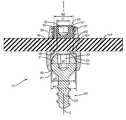
- FIG. 1illustrates one embodiment of a screw assembly 10 that includes a screw 20 and a receiver 30 .
- the screw 20includes an elongated shape with a first end mounted within a vertebral member 200 and a second end extending outward above the vertebral member 200 .
- the receiver 30is deformed to operatively connect to the second end of the screw 20 and is movably connected to the screw 20 to accommodate the longitudinal member 100 positioned at various angular positions.
- the receiver 30includes a channel 31 sized to receive the longitudinal member 100 .
- a set screw 50attaches to the receiver 30 to capture the longitudinal member 100 within the channel 31 .
- the screw 20includes a head 21 positioned at an end of a shaft 23 .
- the head 21is substantially spherical and may include a driving feature 22 for insertion of the screw 20 into the vertebral member 200 .
- Head 21may also include other shapes, such as an elliptical shape.
- the embodiment illustratedincludes a hex recess driving feature 22 .
- Other types of driving features 22may be appropriate, including for example, slotted, star, TORX, and cross-shaped features.
- Head 21includes a width d 1 as illustrated in FIG. 3 .
- the head 21includes an exterior surface that is substantially smooth to facilitate pivoting movement with the receiver 30 .
- the shaft 23may include threads along an entirety or a limited portion to facilitate insertion into the vertebral member 200 .
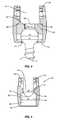
- Receiver 30provides a connection between the screw 20 and longitudinal member 100 .
- Receiver 30includes a first end 32 that faces towards the vertebral member 200 , and a second end 33 that faces away.
- a chamber 34is positioned between the first and second ends 32 , 33 and is sized to receive the head 21 .
- Chamber 34includes a central section with a width w 1 formed between interior sidewalls 35 .
- the width w 1is substantially equal to the width d 1 .
- the width w 1may be larger than the width d 1 for the head 21 to move laterally within the chamber 34 .
- the width w 1is smaller than the width d 1 .
- the receiver 30may be constructed as a unitary piece. As illustrated in FIG. 3 , the receiver 30 defines an outer extent and also an inner wall of the chamber 34 at the vertical level where the head 21 is positioned. In one embodiment, the receiver 30 is circumferentially un-reinforced with the receiver 30 including adequate strength to maintain the screw 20 .
- An upper constriction 40 with a width w 2is formed in the receiver 30 .
- the upper constriction 40 width w 2is smaller than the width w 1 of the central section 49 of the chamber 34 , and is smaller than the head width d 1 thus preventing the head 21 from moving upward in the receiver 30 beyond this level.
- the upper constriction 40may be formed by the receiver 30 , by a crown 60 as explained below, or both.
- the upper constriction 40is formed by the receiver 30 , and specifically a ledge 36 that extends inward from the sidewalls 35 at an upper section of the chamber 34 away from the first end 32 .
- the second end 33 of the receiver 30includes a channel 31 sized to receive the longitudinal member 100 .
- Channel 31terminates at a lower edge 38 that may include a curved shape to approximate the longitudinal member 100 .
- Threads 37may be positioned towards the second end 33 to engage with the set screw 50 .
- the threads 37are positioned on the interior of the receiver 30 facing towards the channel 31 .
- the threads 37are on the exterior of the receiver 30 .
- An interior of the receiver 30may be open between the first and second ends 32 , 33 . This open space provides for insertion of a driver through the receiver 30 to engage the driving feature 22 on the screw 20 and mount the screw 20 within the vertebral member 200 .
- Set screw 50attaches to the receiver 30 and captures the longitudinal member 100 within the channel 31 .
- the set screw 50may be sized to fit within the interior of the channel 31 and include exterior threads 51 that engage threads 37 on the receiver 30 .
- a driving feature 52may be positioned on a top side to receive a tool during engagement with the receiver 30 .
- Driving feature 52may be substantially the same or different than driving feature 22 .
- FIG. 6illustrates another embodiment with the set screw 50 mounted on an exterior of the receiver 30 .
- Set screw 50includes a central opening and is sized to extend around the second end 33 . Threads 51 are positioned on an inner surface of the central opening to engage with the external threads 37 on the receiver 30 .
- the set screw 50 and receiver 30may be constructed for the top side of the set screw 50 to be flush with or recessed within the second end 33 when mounted with the receiver 30 .
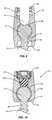
- a crown 60may be positioned within the receiver 30 between the screw 20 and longitudinal member 100 .
- Crown 60includes a first end 61 that faces towards the screw 20 , and a second end 62 that faces towards the longitudinal member 100 .
- a shelf 63is formed on the exterior between the ends 61 , 62 , and a neck 65 extends upward beyond the shelf 63 .
- An opening 66 with a width x 1extends through the crown 60 to provide access to the driving feature 22 on the screw 20 .
- An inner surface 64 of the crown 60may be curved to accommodate the spherical head 21 .
- the curve of the inner surface 64matches the curve of the head 21 to facilitate pivoting movement of the screw 20 .
- the curve of the inner surface 64may be greater than or less than the curve of the head 21 .
- the upper constriction 40is formed by the crown 60 .
- Receiver 30includes a ledge 36 sized to receive the crown 60 .
- the space formed between the ledge 36includes a width that is greater than the width d 1 of the head 21 .
- Crown 60is positioned within this space and extends inward from the sidewalls 35 and ledge 36 .
- Crown 60includes an opening 66 including a width x 1 that is smaller than the width d 1 of the head 21 .
- Crown 60thereby forms the upper constriction 40 that prevents the screw 20 from moving vertically upward within the receiver 30 . Because the crown 60 forms the upper constriction 40 , the opening width x 1 is the width of the upper constriction w 2 .
- the receiver 30is deformable to form a lower constriction 41 and capture the screw 20 .
- the receiver 30is deformed from a first orientation with the chamber 34 sized to receive the screw head 21 , and a second orientation that captures the screw 20 .
- the deformationprovides for loading the screw head 21 into the chamber 34 through the first end 32 while the receiver 30 is in the first orientation. Once the screw head 21 is in the chamber 34 , the receiver 30 is deformed to the second orientation to capture the screw head 21 .
- FIG. 5illustrates one embodiment with the receiver 30 in the first, un-deformed orientation.
- the chamber 34includes a width w 1 sized to receive the screw head 21 when it is inserted through the first end 32 .
- width w 1is substantially equal throughout the levels of the chamber 34 .
- FIG. 6illustrates another embodiment of the receiver 30 in the first orientation with the first end 32 including a smaller width than an interior width w 1 of the chamber 34 .
- the width of the first end 32is larger than width d 1 to receive the screw head 21 and allow it to pass into the central section 49 of the chamber 34 .
- FIG. 7illustrates an embodiment with the width of the first end 32 being larger than the width w 1 of the central section 49 .
- the width of the screw head 21may be substantially equal to the width w 1 as illustrated in FIG. 3 . In another embodiment, the width of the screw head 21 is less than the width w 1 which allows for the screw head 21 to laterally move within the chamber 34 .
- Deformationforms a lower constriction 41 to capture the screw head 21 within the chamber 34 .
- the deformationdeforms the section inward towards a centerline C of the assembly 10 .
- the lower constriction 41includes a width w 3 that is smaller than the head width d 1 . This is clearly shown in FIG. 3 with the first end 32 deformed inwards to form the lower constriction 41 that is smaller than the width d 1 to prevent the head 21 from escaping from the chamber 34 .
- FIGS. 8A and 8Billustrate schematic bottom views of the receiver 30 .
- the first end 32 of the receiver 30forms a continuous wall that encloses the chamber 34 .
- FIG. 8Aillustrates the receiver 30 in the first orientation with a width w 3 ′ formed at the first end 32 .
- Width w 3 ′is greater than or equal to the width d 1 of the head 21 to allow insertion of the head 21 into the chamber 34 . Because of the relative sizes, the first end 32 does not expand due to insertion of the head 21 .
- the receiver 30in the second orientation with the first end 32 being deformed to a smaller width w 3 thus forming the lower constriction 41 to retain the head 21 .
- the head 21includes a greater width than the first end 32 . Insertion of the head 21 causes either deformation of the head 21 or deformation of the receiver 20 to allow for insertion.
- the lower constriction 41may be formed at different levels along the chamber 34 .
- FIG. 3includes the lower constriction 41 formed at a lower level of the chamber 34 with deformation of the first end 32 .
- FIG. 9illustrates an embodiment with deformation occurring at an upper level with the lower constriction 41 spaced inward from the first end 32 .
- the lower constriction 41further forms a seat that is contacted by the lower surface of the head 21 when the set screw 50 engages the longitudinal member 100 .
- the lower constriction 41may include a shape that complements the shape of the head 21 .
- FIGS. 3 and 9illustrate embodiments with the surface of the lower constriction 41 that faces the head 21 substantially matching the curvature of the head 21 .
- FIG. 4illustrates an embodiment with the surface of the lower constriction 41 including a non-matching head shape.
- the surface of the lower constriction 41is substantially flat with the head 21 being curved.
- the seatis formed by a curved section that is intermediate between two elongated, flat sections.
- FIG. 3illustrates the chamber 34 sized and positioned such that a portion of the head 21 extends outward beyond the first end 32 of the receiver 30 .
- the height of the chamber 34 measured between the constrictions 40 , 41is such that the lower constriction 41 contacts an intermediate section of the head 21 .
- the head 21is contained above the lower constriction 41 with the shank 23 extending outward beyond the opening in the lower constriction 41 .
- Deformation of the receiver 30may be performed using a variety of techniques.
- One techniqueis orbital forming which is a cold metal forming process during which the workpiece (the receiver 30 in this case) is captured between upper and lower dies. The process features one or the other of these dies orbiting relative to the other with a compression force applied therebetween. Due to this orbiting motion over the workpiece, the resultant localized forces can achieve a high degree of deformation at a relatively low compression force level.
- FIGS. 11A-11Ddepict exemplary process steps that may be used to retain the screw head 21 within the receiver chamber 34 .
- the receiver 30 illustrated in FIG. 3is shown. It should be understood that other receiver embodiments may be formed using the illustrated process steps.
- a first step illustrated in FIG. 11Athe receiver 30 is positioned into a holding fixture 300 .
- the fixture 300is depicted as a pair of opposed jaws, but other types of fixtures, including a chuck, a vise, a clamp, or other device known in the art may be used.
- the fixture 300is adjusted to a position as shown in FIG. 11B to secure the receiver 30 . Once secured, the crown 60 is inserted into the chamber 34 .
- FIG. 11Cdepicts, a forming tool 310 is brought into contact with the portion of the receiver 30 to be deformed.
- the first end 32is deformed under the influence of a deforming pressure P applied through the forming tool 310 .
- the receiver 30 , the forming tool 310 , or some combination thereofmay be rotated while the deforming pressure P is applied to the first end 32 .
- the tool 310is held at a fixed angle and progressively deforms the receiver 30 to the second orientation. The first end 32 is thereby deformed to the position shown in FIG.
- the shape of the forming tool 310may vary depending upon the desired shape of the deformed receiver 30 .
- Orbital formingmay also be referred to as spinning, radial riveting, bracketing, spin riveting, peening, or noiseless riveting.
- FIG. 12illustrates one embodiment of the receiver 30 with an exterior contact surface 48 .
- the contact surface 48is initially contacted by the forming tool 310 as illustrated in FIG. 11C .
- the contact surface 48is positioned at an angle ⁇ relative to the first end 32 . This position provides for good contact between the receiver 30 and the forming tool 310 during the deformation.
- the angle ⁇is about 12°.
- Another deformation processincludes a stamping/forming process.
- This processincludes a die that holds the receiver 30 while the head 21 is inserted within the chamber 34 .
- a punchapplies a force to the receiver 30 to deform the receiver 30 towards the second orientation.
- This processmay include a single step to deform the receiver 30 from the first orientation to the second orientation, or may include a series of progressive steps that use different tools or operations to obtain the final form.
- the stepsmay include crimping or rolling operations to compress edges and add rigidity to the receiver 30 .
- Roller formingis another process that may be used to deform the receiver 30 .
- Roller forminguses multiple rollers mounted on a rotating spindle. Relative rotation between the receiver and the spindle cause the rollers to gradually and smoothly deform the receiver 30 thereby forming the lower constriction 41 .
- Spinningis another process for deforming the receiver 30 .
- Spinningincludes mounting the receiver 30 on a lathe.
- a tooloften referred to as a spoon, contacts the receiver 30 and applies a levered force.
- the receiver 30is thereby deformed and shaped over a mandrel or form.
- Magnetic formingmay also be used to deform the receiver 30 .
- This processincludes application of an electric current near the receiver 30 that generates a pulsed magnetic field.
- the fieldcreates a controllable pressure that can be applied to deform the receiver 30 as necessary.
- the processes described aboveinclude exemplary methods to deform the receiver 30 . It should be understood that other known manufacturing processes may be used to deform the receiver 30 to retain the screw 20 . Some exemplary processes that may be used to achieve the desired deformation may include pressing, rolling, welding, spin forming, heading, forging, swaging, staking, and stamping. Those skilled in the art will comprehend other manufacturing techniques that may be used to effectively capture the screw 20 as desired.
- Embodiments including a crown 60originally allow for the screw 20 to be movable between various angular positions.
- the set screw 50engages the receiver 30 and applies a compression force to the longitudinal member 100 . This force is transferred through the crown 60 to the head 21 to secure the screw 20 at a desired angular position.
- FIG. 10includes an embodiment without a crown 60 and the longitudinal member 100 directly contacting the head 21 .
- the compression force applied by the set screw to the longitudinal member 100is transferred to the head to lock the screw 20 at the desired angular position.
- FIG. 13illustrates an embodiment with the chamber 34 including an upper constriction 40 and a lower constriction 41 to capture the screw head 21 .
- the head 21is positioned away from the longitudinal member 100 when the set screw 50 is engaged with the receiver 30 and in contact with the longitudinal member 100 . This provides for the screw 20 to remain movable relative to the receiver 30 once the longitudinal member 100 is secured by the set screw 50 .
- the longitudinal member 100includes an elongated shape to extend across two or more vertebral members 100 .
- FIG. 14illustrates another type of longitudinal member 100 that is secured between vertebral members 200 .
- the longitudinal member 100extends between the sacrum and L 5 .
- Longitudinal members 100may be flexible and constructed from various materials including a resin or polymer compound. Some flexible non-metallic longitudinal members 100 are constructed from materials such as PEEK and UHMWPE. Other types of flexible longitudinal members 100 may comprise braided metallic structures.
- the longitudinal member 100is rigid or semi-rigid and may be constructed from metals, including for example stainless steels, cobalt-chrome, titanium, and shape memory alloys. Further, the longitudinal member 100 may be straight, curved, or comprise one or more curved portions along its length.
- the head 21is substantially spherical to allow multi-axial pivoting of the screw 20 relative to the receiver 30 .
- the screw head 21has other shapes to allow motion in fewer directions.
- a disc-shaped screw head 21may provide motion within a desired plane.
- Head 21may also include a substantially flat surface as illustrated in FIGS. 15 and 16 .
- Head 21may also include friction enhancing features, such as a plurality of serrations, that are configured to engage the bearing surface of the crown 60 once a sufficient clamping force is applied onto the longitudinal member 100 and onto the crown 60 , by the set screw 50 .
- FIG. 15illustrates a screw 20 comprising a head 21 incorporated onto a hook-type screw member 20 .
- the head 21is incorporated onto a type of threaded screw member 20 that is inserted into a plate 500 instead of a bony member.
- the longitudinal member 100is captured within the receiver 30 by the set screw 50 .
- Set screw 50may include a shape to fit within the interior of the receiver 30 as illustrated in FIG. 3 , or on the exterior as illustrated in FIG. 6 .
- the longitudinal member 100may also be captured by other structures, including but not limited to a twist lock and bayonet-type structure.
- the longitudinal member 100may move relative to the vertebral members 200 . This may occur when the patient moves, such as during flexion or extension. During movement of the longitudinal member 100 , the screw assemblies 10 remain attached at fixed locations to the longitudinal member 100 . In one embodiment, the set screws 50 securely attach the receivers 30 to the longitudinal member 100 . In one embodiment, one or more of the receivers 30 may translate along the longitudinal member 100 .
- the movement of the longitudinal member 100may cause the receivers 30 to move relative to the screws 20 .
- the extent of movement between the receivers 30 and the screws 20may vary depending upon the amount of vertebral member movement, and the specific mechanics of the screw assemblies 10 . In embodiments with multiple screw assemblies 10 attached to the longitudinal member 100 , each of the assemblies may move the same or different amounts.
- the longitudinal member 100is attached to the vertebral members 200 with at least two assemblies 10 .
- the longitudinal member 100is movable between a first configuration with a first linear distance between the first and second assemblies 10 , and a second configuration with a second different linear distance between the first and second assemblies 10 .
- the receivers 30remain longitudinally fixed relative to the longitudinal member and movable relative to the screws 20 .
- the longitudinal member 100is constructed from an elastic material that may allow an increase in the distance during a first type of motion. The elastic material may also apply a force to the vertebral members 200 to return the longitudinal member 100 back towards the default, or original position.
- the longitudinal member 100may include a bend or curved section between the assemblies 10 that may become elongated during movement.
Landscapes
- Health & Medical Sciences (AREA)
- Orthopedic Medicine & Surgery (AREA)
- Life Sciences & Earth Sciences (AREA)
- Neurology (AREA)
- Surgery (AREA)
- Heart & Thoracic Surgery (AREA)
- Engineering & Computer Science (AREA)
- Biomedical Technology (AREA)
- Nuclear Medicine, Radiotherapy & Molecular Imaging (AREA)
- Medical Informatics (AREA)
- Molecular Biology (AREA)
- Animal Behavior & Ethology (AREA)
- General Health & Medical Sciences (AREA)
- Public Health (AREA)
- Veterinary Medicine (AREA)
- Surgical Instruments (AREA)
- Prostheses (AREA)
Abstract
Description
Claims (14)
Priority Applications (2)
| Application Number | Priority Date | Filing Date | Title |
|---|---|---|---|
| US12/038,572US8057519B2 (en) | 2006-01-27 | 2008-02-27 | Multi-axial screw assembly |
| PCT/US2009/034959WO2009108618A1 (en) | 2006-01-27 | 2009-02-24 | Multi-axial screw assembly |
Applications Claiming Priority (3)
| Application Number | Priority Date | Filing Date | Title |
|---|---|---|---|
| US11/341,188US7722652B2 (en) | 2006-01-27 | 2006-01-27 | Pivoting joints for spinal implants including designed resistance to motion and methods of use |
| US11/493,447US7833252B2 (en) | 2006-01-27 | 2006-07-26 | Pivoting joints for spinal implants including designed resistance to motion and methods of use |
| US12/038,572US8057519B2 (en) | 2006-01-27 | 2008-02-27 | Multi-axial screw assembly |
Related Parent Applications (1)
| Application Number | Title | Priority Date | Filing Date |
|---|---|---|---|
| US11/493,447Continuation-In-PartUS7833252B2 (en) | 2006-01-27 | 2006-07-26 | Pivoting joints for spinal implants including designed resistance to motion and methods of use |
Publications (2)
| Publication Number | Publication Date |
|---|---|
| US20080147121A1 US20080147121A1 (en) | 2008-06-19 |
| US8057519B2true US8057519B2 (en) | 2011-11-15 |
Family
ID=39528446
Family Applications (1)
| Application Number | Title | Priority Date | Filing Date |
|---|---|---|---|
| US12/038,572Active2028-07-28US8057519B2 (en) | 2006-01-27 | 2008-02-27 | Multi-axial screw assembly |
Country Status (2)
| Country | Link |
|---|---|
| US (1) | US8057519B2 (en) |
| WO (1) | WO2009108618A1 (en) |
Cited By (29)
| Publication number | Priority date | Publication date | Assignee | Title |
|---|---|---|---|---|
| US20100160974A1 (en)* | 2008-12-22 | 2010-06-24 | Zimmer Spine, Inc. | Method of Bone Anchor Assembly |
| US20130296945A1 (en)* | 2000-09-22 | 2013-11-07 | Depuy Spine, Inc. | Locking Cap Assembly for Spinal Fixation Instrumentation |
| US20140074169A1 (en)* | 2012-09-13 | 2014-03-13 | Warsaw Orthopedic, Inc. | Spinal correction system and method |
| US8911479B2 (en) | 2012-01-10 | 2014-12-16 | Roger P. Jackson | Multi-start closures for open implants |
| US9034022B2 (en) | 2012-08-09 | 2015-05-19 | Spinecraft, LLC | Locking force augmentation features for surgical screw assembly |
| US9179957B2 (en) | 2012-08-09 | 2015-11-10 | Spinecraft, LLC | Systems, assemblies and methods for spinal derotation |
| US9271759B2 (en) | 2012-03-09 | 2016-03-01 | Institute Of Musculoskeletal Science And Education, Ltd. | Pedicle screw assembly with locking cap |
| US9707100B2 (en) | 2015-06-25 | 2017-07-18 | Institute for Musculoskeletal Science and Education, Ltd. | Interbody fusion device and system for implantation |
| WO2020018860A1 (en) | 2018-07-19 | 2020-01-23 | Warsaw Orthopedic, Inc. | Break-off set screw |
| WO2020018864A1 (en) | 2018-07-19 | 2020-01-23 | Warsaw Orthopedic, Inc. | Antenna placement for a digital set screw |
| WO2020018862A1 (en) | 2018-07-19 | 2020-01-23 | Warsaw Orthopedic, Inc. | Set screw sensor placement |
| US10610265B1 (en) | 2017-07-31 | 2020-04-07 | K2M, Inc. | Polyaxial bone screw with increased angulation |
| WO2021007469A1 (en) | 2019-07-11 | 2021-01-14 | Warsaw Orthopedic., Inc. | Temperature sensing array for set screw infection |
| EP3900655A1 (en) | 2020-04-22 | 2021-10-27 | Warsaw Orthopedic, Inc. | System and method for post-operative assessment of spinal motion and implant-based strain correlation |
| EP3900627A1 (en) | 2020-04-22 | 2021-10-27 | Warsaw Orthopedic, Inc. | Motion limiting apparatus for assessing status of spinal implants |
| US11298162B2 (en) | 2018-07-19 | 2022-04-12 | Warsaw Orthopedic, Inc. | Load sensing assembly for a spinal implant |
| US11311315B2 (en) | 2020-01-03 | 2022-04-26 | Warsaw Orthopedic, Inc. | Multi-plate capacitive assembly for a spinal implant |
| US11382512B2 (en) | 2020-01-03 | 2022-07-12 | Warsaw Orthopedic, Inc. | Energy transfer system for spinal implants |
| EP4094678A1 (en) | 2021-05-25 | 2022-11-30 | Warsaw Orthopedic, Inc. | Systems for real-time monitoring of bone correction |
| US11517398B2 (en) | 2020-01-03 | 2022-12-06 | Warsaw Orthopedic, Inc. | Energy transfer system for spinal implants |
| WO2023199225A1 (en) | 2022-04-12 | 2023-10-19 | Warsaw Orthopedic, Inc. | Smart implant designs for housing a power source, antenna, gauges, and microelectronics |
| EP4282358A1 (en) | 2022-05-18 | 2023-11-29 | Warsaw Orthopedic, Inc. | Modular set screw design for housing microelectronics and lateral coil antenna |
| US11872143B2 (en) | 2016-10-25 | 2024-01-16 | Camber Spine Technologies, LLC | Spinal fusion implant |
| US11877935B2 (en) | 2016-10-18 | 2024-01-23 | Camber Spine Technologies, LLC | Implant with deployable blades |
| US11915089B2 (en) | 2021-07-09 | 2024-02-27 | Warsaw Orthopedic, Inc. | Faraday cage for digital set screw probe reader |
| US12114898B2 (en) | 2020-11-19 | 2024-10-15 | K2M, Inc. | Modular head assembly for spinal fixation |
| WO2024224328A1 (en) | 2023-04-25 | 2024-10-31 | Warsaw Orthopedic, Inc. | Smart spine implant for adjacent level kinematic and biomechanical assessment |
| US12262921B2 (en) | 2020-06-26 | 2025-04-01 | K2M, Inc. | Modular head assembly |
| US12396679B2 (en) | 2018-07-19 | 2025-08-26 | Warsaw Orthopedic, Inc. | System and method for post-operative assessment of spinal motion and implant-based strain correlation |
Families Citing this family (38)
| Publication number | Priority date | Publication date | Assignee | Title |
|---|---|---|---|---|
| US7833250B2 (en) | 2004-11-10 | 2010-11-16 | Jackson Roger P | Polyaxial bone screw with helically wound capture connection |
| US8876868B2 (en) | 2002-09-06 | 2014-11-04 | Roger P. Jackson | Helical guide and advancement flange with radially loaded lip |
| US6716214B1 (en)* | 2003-06-18 | 2004-04-06 | Roger P. Jackson | Polyaxial bone screw with spline capture connection |
| US7377923B2 (en) | 2003-05-22 | 2008-05-27 | Alphatec Spine, Inc. | Variable angle spinal screw assembly |
| US8366753B2 (en) | 2003-06-18 | 2013-02-05 | Jackson Roger P | Polyaxial bone screw assembly with fixed retaining structure |
| US8926670B2 (en) | 2003-06-18 | 2015-01-06 | Roger P. Jackson | Polyaxial bone screw assembly |
| US7967850B2 (en) | 2003-06-18 | 2011-06-28 | Jackson Roger P | Polyaxial bone anchor with helical capture connection, insert and dual locking assembly |
| US7766915B2 (en) | 2004-02-27 | 2010-08-03 | Jackson Roger P | Dynamic fixation assemblies with inner core and outer coil-like member |
| US7776067B2 (en) | 2005-05-27 | 2010-08-17 | Jackson Roger P | Polyaxial bone screw with shank articulation pressure insert and method |
| US8926672B2 (en) | 2004-11-10 | 2015-01-06 | Roger P. Jackson | Splay control closure for open bone anchor |
| US9168069B2 (en) | 2009-06-15 | 2015-10-27 | Roger P. Jackson | Polyaxial bone anchor with pop-on shank and winged insert with lower skirt for engaging a friction fit retainer |
| US8444681B2 (en) | 2009-06-15 | 2013-05-21 | Roger P. Jackson | Polyaxial bone anchor with pop-on shank, friction fit retainer and winged insert |
| US7901437B2 (en) | 2007-01-26 | 2011-03-08 | Jackson Roger P | Dynamic stabilization member with molded connection |
| US7722652B2 (en) | 2006-01-27 | 2010-05-25 | Warsaw Orthopedic, Inc. | Pivoting joints for spinal implants including designed resistance to motion and methods of use |
| US8979904B2 (en) | 2007-05-01 | 2015-03-17 | Roger P Jackson | Connecting member with tensioned cord, low profile rigid sleeve and spacer with torsion control |
| US8998958B2 (en)* | 2007-12-20 | 2015-04-07 | Aesculap Implant Systems, Llc | Locking device introducer instrument |
| AU2010260521C1 (en) | 2008-08-01 | 2013-08-01 | Roger P. Jackson | Longitudinal connecting member with sleeved tensioned cords |
| US11229457B2 (en) | 2009-06-15 | 2022-01-25 | Roger P. Jackson | Pivotal bone anchor assembly with insert tool deployment |
| US8998959B2 (en) | 2009-06-15 | 2015-04-07 | Roger P Jackson | Polyaxial bone anchors with pop-on shank, fully constrained friction fit retainer and lock and release insert |
| US9668771B2 (en) | 2009-06-15 | 2017-06-06 | Roger P Jackson | Soft stabilization assemblies with off-set connector |
| CN103826560A (en) | 2009-06-15 | 2014-05-28 | 罗杰.P.杰克逊 | Polyaxial Bone Anchor with Socket Stem and Winged Inserts with Friction Fit Compression Collars |
| ES2461843T3 (en) | 2010-12-23 | 2014-05-21 | Biedermann Technologies Gmbh & Co. Kg | Bone anchoring device |
| US9655655B2 (en) | 2011-08-16 | 2017-05-23 | Aesculap Implant Systems, Llc | Two step locking screw assembly |
| KR101199458B1 (en)* | 2012-02-17 | 2012-11-09 | 고려대학교 산학협력단 | Apparatus for fixation of spine |
| ES2563785T3 (en)* | 2012-06-01 | 2016-03-16 | Biedermann Technologies Gmbh & Co. Kg | Polyaxial bone anchoring device |
| US8911478B2 (en) | 2012-11-21 | 2014-12-16 | Roger P. Jackson | Splay control closure for open bone anchor |
| WO2014088522A2 (en)* | 2012-12-07 | 2014-06-12 | Spi̇namer Sağlik Ürünleri̇ Sanayi̇ Ve Teknoloji̇ Li̇mi̇ted Şi̇rketi̇ | Ortovia spinal system |
| US10058354B2 (en) | 2013-01-28 | 2018-08-28 | Roger P. Jackson | Pivotal bone anchor assembly with frictional shank head seating surfaces |
| US8852239B2 (en) | 2013-02-15 | 2014-10-07 | Roger P Jackson | Sagittal angle screw with integral shank and receiver |
| US9566092B2 (en) | 2013-10-29 | 2017-02-14 | Roger P. Jackson | Cervical bone anchor with collet retainer and outer locking sleeve |
| US9717533B2 (en) | 2013-12-12 | 2017-08-01 | Roger P. Jackson | Bone anchor closure pivot-splay control flange form guide and advancement structure |
| US9451993B2 (en) | 2014-01-09 | 2016-09-27 | Roger P. Jackson | Bi-radial pop-on cervical bone anchor |
| US10064658B2 (en) | 2014-06-04 | 2018-09-04 | Roger P. Jackson | Polyaxial bone anchor with insert guides |
| US9597119B2 (en) | 2014-06-04 | 2017-03-21 | Roger P. Jackson | Polyaxial bone anchor with polymer sleeve |
| US10575876B2 (en)* | 2016-04-20 | 2020-03-03 | K2M, Inc. | Spinal stabilization assemblies with bone hooks |
| EP3766443B1 (en) | 2019-07-18 | 2023-02-15 | Biedermann Technologies GmbH & Co. KG | Bone anchoring device |
| EP3871624B1 (en) | 2020-02-25 | 2023-07-19 | Biedermann Technologies GmbH & Co. KG | Bone anchoring device |
| US11589904B2 (en)* | 2021-03-31 | 2023-02-28 | Bret Michael Berry | Pedicle screw with detachable polyaxial head |
Citations (150)
| Publication number | Priority date | Publication date | Assignee | Title |
|---|---|---|---|---|
| US4304011A (en) | 1980-08-25 | 1981-12-08 | Whelan Iii Edward J | Semi-constrained metacarpophalangeal prosthesis |
| US4946458A (en) | 1986-04-25 | 1990-08-07 | Harms Juergen | Pedicle screw |
| US5084048A (en) | 1989-07-12 | 1992-01-28 | Sulzer Brothers Limited | Implant for vertebrae with spinal stabilizer |
| US5190543A (en) | 1990-11-26 | 1993-03-02 | Synthes (U.S.A.) | Anchoring device |
| US5443467A (en) | 1993-03-10 | 1995-08-22 | Biedermann Motech Gmbh | Bone screw |
| US5474555A (en) | 1990-04-26 | 1995-12-12 | Cross Medical Products | Spinal implant system |
| US5480041A (en) | 1994-06-27 | 1996-01-02 | Turner; Eugene M. | Trailer-mounted crane |
| US5549608A (en) | 1995-07-13 | 1996-08-27 | Fastenetix, L.L.C. | Advanced polyaxial locking screw and coupling element device for use with rod fixation apparatus |
| US5591166A (en) | 1995-03-27 | 1997-01-07 | Smith & Nephew Richards, Inc. | Multi angle bone bolt |
| US5669911A (en) | 1995-04-13 | 1997-09-23 | Fastenetix, L.L.C. | Polyaxial pedicle screw |
| US5728098A (en) | 1996-11-07 | 1998-03-17 | Sdgi Holdings, Inc. | Multi-angle bone screw assembly using shape-memory technology |
| US5733285A (en) | 1995-07-13 | 1998-03-31 | Fastenetix, Llc | Polyaxial locking mechanism |
| US5797911A (en) | 1996-09-24 | 1998-08-25 | Sdgi Holdings, Inc. | Multi-axial bone screw assembly |
| US5810819A (en) | 1997-05-15 | 1998-09-22 | Spinal Concepts, Inc. | Polyaxial pedicle screw having a compression locking rod gripping mechanism |
| US5863293A (en) | 1996-10-18 | 1999-01-26 | Spinal Innovations | Spinal implant fixation assembly |
| US5882350A (en) | 1995-04-13 | 1999-03-16 | Fastenetix, Llc | Polyaxial pedicle screw having a threaded and tapered compression locking mechanism |
| US5885286A (en) | 1996-09-24 | 1999-03-23 | Sdgi Holdings, Inc. | Multi-axial bone screw assembly |
| US5888204A (en) | 1996-04-15 | 1999-03-30 | Fastenetix, Llc | Acetabular cup having capped polyaxial locking screws |
| US5891145A (en) | 1997-07-14 | 1999-04-06 | Sdgi Holdings, Inc. | Multi-axial screw |
| US5989254A (en) | 1997-05-20 | 1999-11-23 | Katz; Akiva Raphael | Pedicle screw assembly |
| US6063090A (en) | 1996-12-12 | 2000-05-16 | Synthes (U.S.A.) | Device for connecting a longitudinal support to a pedicle screw |
| US6074391A (en) | 1997-06-16 | 2000-06-13 | Howmedica Gmbh | Receiving part for a retaining component of a vertebral column implant |
| US6082923A (en) | 1998-03-16 | 2000-07-04 | Dana Corporation | Converging sphere joint assembly |
| US6146421A (en) | 1997-08-04 | 2000-11-14 | Gordon, Maya, Roberts And Thomas, Number 1, Llc | Multiple axis intervertebral prosthesis |
| US6248105B1 (en) | 1997-05-17 | 2001-06-19 | Synthes (U.S.A.) | Device for connecting a longitudinal support with a pedicle screw |
| US6258089B1 (en) | 1998-05-19 | 2001-07-10 | Alphatec Manufacturing, Inc. | Anterior cervical plate and fixation system |
| US6261287B1 (en) | 1992-03-02 | 2001-07-17 | Stryker Trauma Gmbh | Apparatus for bracing vertebrae |
| US6280442B1 (en) | 1999-09-01 | 2001-08-28 | Sdgi Holdings, Inc. | Multi-axial bone screw assembly |
| US6290703B1 (en) | 1996-05-13 | 2001-09-18 | Stryker France S.A. | Device for fixing the sacral bone to adjacent vertebrae during osteosynthesis of the backbone |
| US6368321B1 (en) | 2000-12-04 | 2002-04-09 | Roger P. Jackson | Lockable swivel head bone screw |
| US6440137B1 (en) | 2000-04-18 | 2002-08-27 | Andres A. Horvath | Medical fastener cap system |
| US20020138076A1 (en) | 2000-12-27 | 2002-09-26 | Biederman Motech Gmbh | Screw |
| US20030045879A1 (en) | 2001-07-04 | 2003-03-06 | Richard Minfelde | Connector for a spinal fixation member |
| US6554834B1 (en) | 1999-10-07 | 2003-04-29 | Stryker Spine | Slotted head pedicle screw assembly |
| US6605090B1 (en) | 2000-10-25 | 2003-08-12 | Sdgi Holdings, Inc. | Non-metallic implant devices and intra-operative methods for assembly and fixation |
| US6626908B2 (en) | 2000-07-22 | 2003-09-30 | Corin Spinal Systems Limited | Pedicle attachment assembly |
| US20040049272A1 (en) | 1999-10-22 | 2004-03-11 | Archus Orthopedics, Inc. | Facet arthroplasty devices and methods |
| US6716214B1 (en) | 2003-06-18 | 2004-04-06 | Roger P. Jackson | Polyaxial bone screw with spline capture connection |
| US6733502B2 (en) | 2002-05-15 | 2004-05-11 | Cross Medical Products, Inc. | Variable locking spinal screw having a knurled collar |
| US6736820B2 (en) | 2000-11-10 | 2004-05-18 | Biedermann Motech Gmbh | Bone screw |
| US20040102781A1 (en) | 2002-11-25 | 2004-05-27 | U & I Corporation | Bone fixation apparatus, method and tool for assembling the same |
| US6749361B2 (en) | 1997-10-06 | 2004-06-15 | Werner Hermann | Shackle element for clamping a fixation rod, a method for making a shackle element, a hook with a shackle element and a rode connector with a shackle element |
| US20040176766A1 (en) | 2002-02-13 | 2004-09-09 | Shluzas Alan E. | Apparatus for connecting a longitudinal member to a bone portion |
| US20040181224A1 (en) | 2003-03-11 | 2004-09-16 | Biedermann Motech Gmbh | Anchoring element for use in spine or bone surgery, methods for use and production thereof |
| US6793658B2 (en) | 2001-04-06 | 2004-09-21 | Society De Fabrication De Material Orthopedique, S.A. | Anterior plating system and method |
| US20040186473A1 (en) | 2003-03-21 | 2004-09-23 | Cournoyer John R. | Spinal fixation devices of improved strength and rigidity |
| US20040225289A1 (en) | 2003-05-07 | 2004-11-11 | Biedermann Motech Gmbh | Dynamic anchoring device and dynamic stabilization device for bones, in particular for vertebrae, with such an anchoring device |
| US20040249380A1 (en) | 2001-01-12 | 2004-12-09 | Craig Glascott | Polyaxial screw with improved locking |
| US20040260284A1 (en) | 2003-06-23 | 2004-12-23 | Matthew Parker | Anti-splay pedicle screw |
| US20040267264A1 (en)* | 2003-06-27 | 2004-12-30 | Konieczynski David D. | Polyaxial bone screw |
| US20050033431A1 (en) | 2003-08-05 | 2005-02-10 | Charles Gordon | Artificial functional spinal unit assemblies |
| US20050033439A1 (en) | 2003-08-05 | 2005-02-10 | Charles Gordon | Artificial functional spinal unit assemblies |
| US20050033432A1 (en) | 2003-08-05 | 2005-02-10 | Charles Gordon | Artificial spinal unit assemblies |
| WO2005016194A2 (en) | 2003-08-05 | 2005-02-24 | Flexuspine, Inc. | Artificial spinal unit assemblies |
| US20050049588A1 (en) | 2003-08-28 | 2005-03-03 | Jackson Roger P. | Polyaxial bone screw with split retainer ring |
| US20050049589A1 (en) | 2003-08-28 | 2005-03-03 | Jackson Roger P. | Polyaxial bone screw apparatus |
| US6918911B2 (en) | 2002-03-27 | 2005-07-19 | Biedermann Motech Gmbh | Bone anchoring device for stabilizing bone segments and seat part of a bone anchoring device |
| US20050187548A1 (en) | 2004-01-13 | 2005-08-25 | Butler Michael S. | Pedicle screw constructs for spine fixation systems |
| US20050192571A1 (en) | 2004-02-27 | 2005-09-01 | Custom Spine, Inc. | Polyaxial pedicle screw assembly |
| EP1570794A1 (en) | 2004-03-04 | 2005-09-07 | U & I Corporation | Bone fixation apparatus, method and tool for assembling the same |
| US20050203516A1 (en) | 2004-03-03 | 2005-09-15 | Biedermann Motech Gmbh | Anchoring element and stabilization device for the dynamic stabilization of vertebrae or bones using such anchoring elements |
| US6945972B2 (en) | 2000-08-24 | 2005-09-20 | Synthes | Apparatus for connecting a bone fastener to a longitudinal rod |
| US20050209698A1 (en) | 2003-08-05 | 2005-09-22 | Gordon Charles R | Expandable intervertebral implant |
| US20050228385A1 (en) | 2004-04-08 | 2005-10-13 | Globus Medical Inc. | Polyaxial screw |
| US6964666B2 (en) | 2003-04-09 | 2005-11-15 | Jackson Roger P | Polyaxial bone screw locking mechanism |
| US20050267472A1 (en) | 2002-03-27 | 2005-12-01 | Biedermann Motech Gmbh | Bone anchoring device for stabilising bone segments and seat part of a bone anchoring device |
| US6974460B2 (en) | 2001-09-14 | 2005-12-13 | Stryker Spine | Biased angulation bone fixation assembly |
| US6974461B1 (en) | 1999-09-14 | 2005-12-13 | Dietmar Wolter | Fixation system for bones |
| US20050277928A1 (en) | 2004-06-14 | 2005-12-15 | Boschert Paul F | Spinal implant fixation assembly |
| US20050277919A1 (en)* | 2004-05-28 | 2005-12-15 | Depuy Spine, Inc. | Anchoring systems and methods for correcting spinal deformities |
| US20050277925A1 (en)* | 2004-06-09 | 2005-12-15 | Mujwid James R | Spinal fixation device with internal drive structure |
| US20050288668A1 (en) | 2002-06-24 | 2005-12-29 | Bernhard Brinkhaus | Spinal column support system |
| US6991632B2 (en) | 2001-09-28 | 2006-01-31 | Stephen Ritland | Adjustable rod and connector device and method of use |
| US20060036242A1 (en) | 2004-08-10 | 2006-02-16 | Nilsson C M | Screw and rod fixation system |
| US7022122B2 (en) | 1997-01-22 | 2006-04-04 | Synthes (U.S.A.) | Device for connecting a longitudinal bar to a pedicle screw |
| US20060084979A1 (en) | 2003-04-09 | 2006-04-20 | Jackson Roger P | Polyaxial bone screw with uploaded threaded shank and method of assembly and use |
| US7060067B2 (en) | 2002-08-16 | 2006-06-13 | Sdgi Holdings, Inc. | Systems, instrumentation and techniques for retaining fasteners relative to a bone plate |
| US20060161152A1 (en) | 2004-10-25 | 2006-07-20 | Alphaspine, Inc. | Bone fixation systems and methods of assembling and/or installing the same |
| US7081117B2 (en) | 2000-09-22 | 2006-07-25 | Depuy Acromed, Inc. | Locking cap assembly for spinal fixation instrumentation |
| US7081116B1 (en) | 1999-06-14 | 2006-07-25 | Scient'x | Implant for osteosynthesis device in particular of the backbone |
| US20060173454A1 (en) | 2003-10-21 | 2006-08-03 | Innovative Spinal Technologies | Internal structure stabilization system for spanning three or more structures |
| US7090674B2 (en) | 2003-11-03 | 2006-08-15 | Spinal, Llc | Bone fixation system with low profile fastener |
| US20060195098A1 (en) | 2005-02-22 | 2006-08-31 | Jorg Schumacher | Implant system and fastening element for an implant system |
| US20060200133A1 (en) | 2005-02-22 | 2006-09-07 | Jackson Roger P | Polyaxial bone screw assembly |
| US20060200131A1 (en) | 2005-03-04 | 2006-09-07 | Depuy Spine Sarl | Constrained motion bone screw assembly |
| US20060200128A1 (en) | 2003-04-04 | 2006-09-07 | Richard Mueller | Bone anchor |
| US20060217715A1 (en) | 2005-03-24 | 2006-09-28 | Depuy Spine, Inc. | Low profile spinal tethering systems |
| US20060217716A1 (en) | 2005-03-22 | 2006-09-28 | Baker Daniel R | Spinal fixation locking mechanism |
| US20060229616A1 (en) | 2005-03-03 | 2006-10-12 | Accin Corporation | Spinal stabilization using bone anchor seat and cross coupling with improved locking feature |
| US7121755B2 (en) | 2001-12-31 | 2006-10-17 | Synthes (U.S.A.) | Device for a ball-and-socket joint type connection of two members |
| US20060235389A1 (en) | 2005-03-03 | 2006-10-19 | Accin Corporation | Spinal stabilization using bone anchor and anchor seat with tangential locking feature |
| US20060235392A1 (en) | 2004-08-27 | 2006-10-19 | Hammer Michael A | Multi-axial connection system |
| US20060235385A1 (en) | 2005-03-31 | 2006-10-19 | Dale Whipple | Low profile polyaxial screw |
| US20060241603A1 (en) | 2003-06-18 | 2006-10-26 | Jackson Roger P | Polyaxial bone screw assembly with fixed retaining structure |
| US20060241600A1 (en) | 2005-03-23 | 2006-10-26 | Ensign Michael D | Percutaneous pedicle screw assembly |
| US20060241769A1 (en) | 2003-08-05 | 2006-10-26 | Southwest Research Institute | Artificial functional spinal implant unit system and method for use |
| US20060247631A1 (en) | 2005-04-27 | 2006-11-02 | Ahn Sae Y | Spinal pedicle screw assembly |
| US20060247636A1 (en) | 1998-06-17 | 2006-11-02 | Hansen Yuan | Methods for securing spinal rods |
| US20060264933A1 (en) | 2005-05-04 | 2006-11-23 | Baker Daniel R | Multistage spinal fixation locking mechanism |
| US7141051B2 (en) | 2003-02-05 | 2006-11-28 | Pioneer Laboratories, Inc. | Low profile spinal fixation system |
| US20060271047A1 (en) | 2005-05-10 | 2006-11-30 | Jackson Roger P | Polyaxial bone screw with compound articulation |
| US20060271053A1 (en) | 2000-12-08 | 2006-11-30 | Synthes (Usa) | Fixation device for bones |
| US20060276792A1 (en) | 2005-05-25 | 2006-12-07 | Ensign Michael D | Low profile pedicle screw and rod assembly |
| US20060276791A1 (en) | 2002-02-13 | 2006-12-07 | Shluzas Alan E | Methods for connecting a longitudinal member to a bone portion |
| US20060276789A1 (en) | 2005-05-27 | 2006-12-07 | Jackson Roger P | Polyaxial bone screw with shank articulation pressure insert and method |
| US20060293659A1 (en) | 2003-07-25 | 2006-12-28 | Alvarez Luis M | Vertebral fixation device for the treatment of spondylolisthesis |
| US20060293666A1 (en) | 2005-05-27 | 2006-12-28 | Wilfried Matthis | Receiving part for connecting a shank of a bone anchoring element to a rod and bone anchoring device with such a receiving part |
| US20060293664A1 (en) | 2005-05-04 | 2006-12-28 | Jorg Schumacher | Orthopaedic anchorage element and osteosynthesis device |
| US7163539B2 (en) | 2004-02-27 | 2007-01-16 | Custom Spine, Inc. | Biased angle polyaxial pedicle screw assembly |
| US20070016199A1 (en) | 2002-08-21 | 2007-01-18 | Boehm Frank H Jr | Systems, methods and tools for spinal surgery |
| US20070016200A1 (en) | 2003-04-09 | 2007-01-18 | Jackson Roger P | Dynamic stabilization medical implant assemblies and methods |
| US7166109B2 (en) | 2001-10-23 | 2007-01-23 | Biedermann Motech Gmbh | Bone fixation device and screw therefor |
| US20070021750A1 (en) | 2005-07-20 | 2007-01-25 | Shluzas Alan E | Apparatus for connecting a longitudinal member to a bone portion |
| US7179261B2 (en) | 2003-12-16 | 2007-02-20 | Depuy Spine, Inc. | Percutaneous access devices and bone anchor assemblies |
| US20070043357A1 (en) | 2005-07-29 | 2007-02-22 | X-Spine Systems, Inc. | Capless multiaxial screw and spinal fixation assembly and method |
| US20070043355A1 (en) | 2003-05-28 | 2007-02-22 | Stephane Bette | Connecting device for spinal osteosynthesis |
| US20070043358A1 (en) | 2005-08-05 | 2007-02-22 | Sdgi Holdings, Inc. | Coupling assemblies for spinal implants |
| US20070043364A1 (en) | 2005-06-17 | 2007-02-22 | Cawley Trace R | Spinal correction system with multi-stage locking mechanism |
| US20070049933A1 (en) | 2005-08-30 | 2007-03-01 | Ahn Sae Y | Multi-axial spinal pedicle screw |
| US7186255B2 (en) | 2004-08-12 | 2007-03-06 | Atlas Spine, Inc. | Polyaxial screw |
| US20070055242A1 (en) | 2005-07-27 | 2007-03-08 | Bailly Frank E | Device for securing spinal rods |
| US20070055241A1 (en) | 2005-07-12 | 2007-03-08 | Wilfried Matthis | Bone anchoring device |
| US20070055240A1 (en) | 2005-07-08 | 2007-03-08 | Wilfried Matthis | Bone anchoring device |
| US20070055244A1 (en) | 2004-02-27 | 2007-03-08 | Jackson Roger P | Dynamic fixation assemblies with inner core and outer coil-like member |
| US7195632B2 (en) | 2001-07-25 | 2007-03-27 | Biedermann Motech Gmbh | Connecting element |
| US20070073291A1 (en) | 2005-09-12 | 2007-03-29 | Seaspine, Inc. | Implant system for Osteosynthesis |
| US20070078460A1 (en) | 2005-08-25 | 2007-04-05 | Robert Frigg | Methods of spinal fixation and instrumentation |
| US20070083199A1 (en) | 2003-09-04 | 2007-04-12 | Abbott Spine | Spinal implant |
| US20070088357A1 (en) | 2005-10-18 | 2007-04-19 | Sdgi Holdings, Inc. | Adjustable bone anchor assembly |
| US20070093818A1 (en) | 2005-08-03 | 2007-04-26 | Lutz Biedermann | Bone anchoring device |
| US20070093826A1 (en) | 2005-10-04 | 2007-04-26 | Hawkes David T | Modular pedicle screw systems and methods of intra-operatively assembling the same |
| US20070093817A1 (en) | 2005-09-29 | 2007-04-26 | Michael Barrus | Spinal fixation system having locking and unlocking devices for use with a multi-planar, taper lock screw |
| US20070093827A1 (en) | 2005-10-04 | 2007-04-26 | Warnick David R | Pedicle screw system with provisional locking aspects |
| US20070093829A1 (en) | 2005-10-06 | 2007-04-26 | Abdou M S | Devices and methods for inter-vertebral orthopedic device placement |
| US20070093821A1 (en) | 2005-09-13 | 2007-04-26 | Stefan Freudiger | Dynamic clamping device for spinal implant |
| US20070093832A1 (en) | 2004-02-27 | 2007-04-26 | Abdelgany Mahmoud F | Spring-loaded, load sharing polyaxial pedicle screw assembly and method |
| US20070093819A1 (en) | 2005-09-19 | 2007-04-26 | Albert Todd J | Bone screw apparatus, system and method |
| US20070100341A1 (en) | 2004-10-20 | 2007-05-03 | Reglos Joey C | Systems and methods for stabilization of bone structures |
| US7214227B2 (en) | 2004-03-22 | 2007-05-08 | Innovative Spinal Technologies | Closure member for a medical implant device |
| US20070106383A1 (en) | 2005-10-03 | 2007-05-10 | Abdou M S | Devices and methods for inter-vertebral orthopedic device placement |
| US20070118123A1 (en) | 2005-11-21 | 2007-05-24 | Strausbaugh William L | Polyaxial bone anchors with increased angulation |
| US20070118117A1 (en) | 2005-10-20 | 2007-05-24 | Ebi, L.P. | Bone fixation assembly |
| US20070118118A1 (en) | 2005-10-21 | 2007-05-24 | Depuy Spine, Inc. | Adjustable bone screw assembly |
| US7223268B2 (en) | 2001-11-27 | 2007-05-29 | Biedermann Mötech GmbH | Locking device for securing a rod-shaped element in a holding element connected to a shank |
| US20070123862A1 (en) | 2004-10-25 | 2007-05-31 | Warnick David R | Bone fixation system and method for using the same |
| US20070123870A1 (en) | 2005-07-18 | 2007-05-31 | Jeon Dong M | Bi-polar screw assembly |
| US20070191839A1 (en) | 2006-01-27 | 2007-08-16 | Sdgi Holdings, Inc. | Non-locking multi-axial joints in a vertebral implant and methods of use |
| US20070233078A1 (en) | 2006-01-27 | 2007-10-04 | Justis Jeff R | Pivoting joints for spinal implants including designed resistance to motion and methods of use |
| WO2007130835A2 (en) | 2006-05-01 | 2007-11-15 | Warsaw Orthopedic, Inc | Bone anchor system utilizing a molded coupling member for coupling a bone anchor to a stabilization member and method therefor |
| US7699876B2 (en) | 2006-11-08 | 2010-04-20 | Ebi, Llc | Multi-axial bone fixation apparatus |
Family Cites Families (3)
| Publication number | Priority date | Publication date | Assignee | Title |
|---|---|---|---|---|
| FR2701650B1 (en)* | 1993-02-17 | 1995-05-24 | Psi | Double shock absorber for intervertebral stabilization. |
| DE102004010844A1 (en)* | 2004-03-05 | 2005-10-06 | Biedermann Motech Gmbh | Stabilizing device for the dynamic stabilization of vertebrae or bones and rod-shaped element for such a stabilization device |
| JP4800787B2 (en)* | 2006-02-15 | 2011-10-26 | セイコーインスツル株式会社 | Step motor drive circuit and analog electronic timepiece |
- 2008
- 2008-02-27USUS12/038,572patent/US8057519B2/enactiveActive
- 2009
- 2009-02-24WOPCT/US2009/034959patent/WO2009108618A1/enactiveApplication Filing
Patent Citations (188)
| Publication number | Priority date | Publication date | Assignee | Title |
|---|---|---|---|---|
| US4304011A (en) | 1980-08-25 | 1981-12-08 | Whelan Iii Edward J | Semi-constrained metacarpophalangeal prosthesis |
| US4946458A (en) | 1986-04-25 | 1990-08-07 | Harms Juergen | Pedicle screw |
| US5084048A (en) | 1989-07-12 | 1992-01-28 | Sulzer Brothers Limited | Implant for vertebrae with spinal stabilizer |
| US5474555A (en) | 1990-04-26 | 1995-12-12 | Cross Medical Products | Spinal implant system |
| US5190543A (en) | 1990-11-26 | 1993-03-02 | Synthes (U.S.A.) | Anchoring device |
| US7128743B2 (en) | 1992-03-02 | 2006-10-31 | Stryker Trauma Gmbh | Apparatus for bracing vertebrae |
| US6261287B1 (en) | 1992-03-02 | 2001-07-17 | Stryker Trauma Gmbh | Apparatus for bracing vertebrae |
| US6537276B2 (en) | 1992-03-02 | 2003-03-25 | Stryker Trauma Gmbh | Apparatus for bracing vertebrae |
| US5443467A (en) | 1993-03-10 | 1995-08-22 | Biedermann Motech Gmbh | Bone screw |
| US5480041A (en) | 1994-06-27 | 1996-01-02 | Turner; Eugene M. | Trailer-mounted crane |
| US5591166A (en) | 1995-03-27 | 1997-01-07 | Smith & Nephew Richards, Inc. | Multi angle bone bolt |
| US5817094A (en) | 1995-04-13 | 1998-10-06 | Fastenetix, Llc | Polyaxial locking screw and coupling element |
| US5669911A (en) | 1995-04-13 | 1997-09-23 | Fastenetix, L.L.C. | Polyaxial pedicle screw |
| USRE37665E1 (en) | 1995-04-13 | 2002-04-16 | Fastenetix, Llc | Polyaxial pedicle screw having a threaded and tapered compression locking mechanism |
| US5882350A (en) | 1995-04-13 | 1999-03-16 | Fastenetix, Llc | Polyaxial pedicle screw having a threaded and tapered compression locking mechanism |
| US5733285A (en) | 1995-07-13 | 1998-03-31 | Fastenetix, Llc | Polyaxial locking mechanism |
| US5549608A (en) | 1995-07-13 | 1996-08-27 | Fastenetix, L.L.C. | Advanced polyaxial locking screw and coupling element device for use with rod fixation apparatus |
| US5888204A (en) | 1996-04-15 | 1999-03-30 | Fastenetix, Llc | Acetabular cup having capped polyaxial locking screws |
| US6290703B1 (en) | 1996-05-13 | 2001-09-18 | Stryker France S.A. | Device for fixing the sacral bone to adjacent vertebrae during osteosynthesis of the backbone |
| US5797911A (en) | 1996-09-24 | 1998-08-25 | Sdgi Holdings, Inc. | Multi-axial bone screw assembly |
| US5885286A (en) | 1996-09-24 | 1999-03-23 | Sdgi Holdings, Inc. | Multi-axial bone screw assembly |
| US5863293A (en) | 1996-10-18 | 1999-01-26 | Spinal Innovations | Spinal implant fixation assembly |
| US5954725A (en) | 1996-11-07 | 1999-09-21 | Sdgi Holdings, Inc. | Multi-angle bone screw assembly using shape memory technology |
| US5728098A (en) | 1996-11-07 | 1998-03-17 | Sdgi Holdings, Inc. | Multi-angle bone screw assembly using shape-memory technology |
| US6132434A (en) | 1996-11-07 | 2000-10-17 | Sdgi Holdings, Inc. | Multi-angle bone screw assembly using shape-memory technology |
| US6454773B1 (en) | 1996-11-07 | 2002-09-24 | Sdgi Holdings, Inc. | Multi-angle bone screw assembly using shape-memory technology |
| US6287311B1 (en) | 1996-11-07 | 2001-09-11 | Sdgi Holdings, Inc. | Multi-angle bone screw assembly using shape-memory technology |
| US6063090A (en) | 1996-12-12 | 2000-05-16 | Synthes (U.S.A.) | Device for connecting a longitudinal support to a pedicle screw |
| US7022122B2 (en) | 1997-01-22 | 2006-04-04 | Synthes (U.S.A.) | Device for connecting a longitudinal bar to a pedicle screw |
| US5810819A (en) | 1997-05-15 | 1998-09-22 | Spinal Concepts, Inc. | Polyaxial pedicle screw having a compression locking rod gripping mechanism |
| US6248105B1 (en) | 1997-05-17 | 2001-06-19 | Synthes (U.S.A.) | Device for connecting a longitudinal support with a pedicle screw |
| US5989254A (en) | 1997-05-20 | 1999-11-23 | Katz; Akiva Raphael | Pedicle screw assembly |
| US6074391A (en) | 1997-06-16 | 2000-06-13 | Howmedica Gmbh | Receiving part for a retaining component of a vertebral column implant |
| US5891145A (en) | 1997-07-14 | 1999-04-06 | Sdgi Holdings, Inc. | Multi-axial screw |
| US6146421A (en) | 1997-08-04 | 2000-11-14 | Gordon, Maya, Roberts And Thomas, Number 1, Llc | Multiple axis intervertebral prosthesis |
| US6749361B2 (en) | 1997-10-06 | 2004-06-15 | Werner Hermann | Shackle element for clamping a fixation rod, a method for making a shackle element, a hook with a shackle element and a rode connector with a shackle element |
| US6082923A (en) | 1998-03-16 | 2000-07-04 | Dana Corporation | Converging sphere joint assembly |
| US6258089B1 (en) | 1998-05-19 | 2001-07-10 | Alphatec Manufacturing, Inc. | Anterior cervical plate and fixation system |
| US6626907B2 (en) | 1998-05-19 | 2003-09-30 | Alphatec Manufacturing, Inc. | Anterior cervical plate and fixation system |
| US20060247636A1 (en) | 1998-06-17 | 2006-11-02 | Hansen Yuan | Methods for securing spinal rods |
| US7081116B1 (en) | 1999-06-14 | 2006-07-25 | Scient'x | Implant for osteosynthesis device in particular of the backbone |
| US6280442B1 (en) | 1999-09-01 | 2001-08-28 | Sdgi Holdings, Inc. | Multi-axial bone screw assembly |
| US20040116929A1 (en) | 1999-09-01 | 2004-06-17 | Barker B. Thomas | Multi-axial bone screw assembly |
| US6660004B2 (en) | 1999-09-01 | 2003-12-09 | Sdgi Holdings, Inc. | Multi-axial bone screw assembly |
| US6974461B1 (en) | 1999-09-14 | 2005-12-13 | Dietmar Wolter | Fixation system for bones |
| US6554834B1 (en) | 1999-10-07 | 2003-04-29 | Stryker Spine | Slotted head pedicle screw assembly |
| US20040049272A1 (en) | 1999-10-22 | 2004-03-11 | Archus Orthopedics, Inc. | Facet arthroplasty devices and methods |
| US6440137B1 (en) | 2000-04-18 | 2002-08-27 | Andres A. Horvath | Medical fastener cap system |
| US6626908B2 (en) | 2000-07-22 | 2003-09-30 | Corin Spinal Systems Limited | Pedicle attachment assembly |
| US6945972B2 (en) | 2000-08-24 | 2005-09-20 | Synthes | Apparatus for connecting a bone fastener to a longitudinal rod |
| US7081117B2 (en) | 2000-09-22 | 2006-07-25 | Depuy Acromed, Inc. | Locking cap assembly for spinal fixation instrumentation |
| US20060235393A1 (en) | 2000-09-22 | 2006-10-19 | Depuy Spine, Inc. | Locking cap assembly for spinal fixation instrumentation |
| US6605090B1 (en) | 2000-10-25 | 2003-08-12 | Sdgi Holdings, Inc. | Non-metallic implant devices and intra-operative methods for assembly and fixation |
| US6736820B2 (en) | 2000-11-10 | 2004-05-18 | Biedermann Motech Gmbh | Bone screw |
| US6368321B1 (en) | 2000-12-04 | 2002-04-09 | Roger P. Jackson | Lockable swivel head bone screw |
| US20060271053A1 (en) | 2000-12-08 | 2006-11-30 | Synthes (Usa) | Fixation device for bones |
| US20020138076A1 (en) | 2000-12-27 | 2002-09-26 | Biederman Motech Gmbh | Screw |
| US20070055238A1 (en) | 2000-12-27 | 2007-03-08 | Biedermann Motech Gmbh | Screw |
| US6869433B2 (en) | 2001-01-12 | 2005-03-22 | Depuy Acromed, Inc. | Polyaxial screw with improved locking |
| US20040249380A1 (en) | 2001-01-12 | 2004-12-09 | Craig Glascott | Polyaxial screw with improved locking |
| US6793658B2 (en) | 2001-04-06 | 2004-09-21 | Society De Fabrication De Material Orthopedique, S.A. | Anterior plating system and method |
| US20030045879A1 (en) | 2001-07-04 | 2003-03-06 | Richard Minfelde | Connector for a spinal fixation member |
| US7195632B2 (en) | 2001-07-25 | 2007-03-27 | Biedermann Motech Gmbh | Connecting element |
| US6974460B2 (en) | 2001-09-14 | 2005-12-13 | Stryker Spine | Biased angulation bone fixation assembly |
| US6991632B2 (en) | 2001-09-28 | 2006-01-31 | Stephen Ritland | Adjustable rod and connector device and method of use |
| US20070118124A1 (en) | 2001-10-23 | 2007-05-24 | Lutz Biedermann | Bone fixation device and screw therefor |
| US7166109B2 (en) | 2001-10-23 | 2007-01-23 | Biedermann Motech Gmbh | Bone fixation device and screw therefor |
| US7223268B2 (en) | 2001-11-27 | 2007-05-29 | Biedermann Mötech GmbH | Locking device for securing a rod-shaped element in a holding element connected to a shank |
| US7121755B2 (en) | 2001-12-31 | 2006-10-17 | Synthes (U.S.A.) | Device for a ball-and-socket joint type connection of two members |
| US20040176766A1 (en) | 2002-02-13 | 2004-09-09 | Shluzas Alan E. | Apparatus for connecting a longitudinal member to a bone portion |
| US7066937B2 (en) | 2002-02-13 | 2006-06-27 | Endius Incorporated | Apparatus for connecting a longitudinal member to a bone portion |
| US7144396B2 (en) | 2002-02-13 | 2006-12-05 | Endius Incorporated | Apparatus for connecting a longitudinal member to a bone portion |
| US20060276791A1 (en) | 2002-02-13 | 2006-12-07 | Shluzas Alan E | Methods for connecting a longitudinal member to a bone portion |
| US20060293665A1 (en) | 2002-02-13 | 2006-12-28 | Shluzas Alan E | Apparatus for connecting a longitudinal member to a bone portion |
| US6918911B2 (en) | 2002-03-27 | 2005-07-19 | Biedermann Motech Gmbh | Bone anchoring device for stabilizing bone segments and seat part of a bone anchoring device |
| US20050267472A1 (en) | 2002-03-27 | 2005-12-01 | Biedermann Motech Gmbh | Bone anchoring device for stabilising bone segments and seat part of a bone anchoring device |
| US6733502B2 (en) | 2002-05-15 | 2004-05-11 | Cross Medical Products, Inc. | Variable locking spinal screw having a knurled collar |
| US20050288668A1 (en) | 2002-06-24 | 2005-12-29 | Bernhard Brinkhaus | Spinal column support system |
| US7060067B2 (en) | 2002-08-16 | 2006-06-13 | Sdgi Holdings, Inc. | Systems, instrumentation and techniques for retaining fasteners relative to a bone plate |
| US20070016199A1 (en) | 2002-08-21 | 2007-01-18 | Boehm Frank H Jr | Systems, methods and tools for spinal surgery |
| US20070016198A1 (en) | 2002-08-21 | 2007-01-18 | Boehm Frank H Jr | Systems, methods and devices for placement of bone anchors and connectors |
| US20040102781A1 (en) | 2002-11-25 | 2004-05-27 | U & I Corporation | Bone fixation apparatus, method and tool for assembling the same |
| US7141051B2 (en) | 2003-02-05 | 2006-11-28 | Pioneer Laboratories, Inc. | Low profile spinal fixation system |
| US20070055235A1 (en) | 2003-02-05 | 2007-03-08 | Pioneer Laboratories, Inc. | Low profile spinal fixation system |
| US20040181224A1 (en) | 2003-03-11 | 2004-09-16 | Biedermann Motech Gmbh | Anchoring element for use in spine or bone surgery, methods for use and production thereof |
| US20040186473A1 (en) | 2003-03-21 | 2004-09-23 | Cournoyer John R. | Spinal fixation devices of improved strength and rigidity |
| US20060200128A1 (en) | 2003-04-04 | 2006-09-07 | Richard Mueller | Bone anchor |
| US6964666B2 (en) | 2003-04-09 | 2005-11-15 | Jackson Roger P | Polyaxial bone screw locking mechanism |
| US20070016200A1 (en) | 2003-04-09 | 2007-01-18 | Jackson Roger P | Dynamic stabilization medical implant assemblies and methods |
| US20060084979A1 (en) | 2003-04-09 | 2006-04-20 | Jackson Roger P | Polyaxial bone screw with uploaded threaded shank and method of assembly and use |
| US20040225289A1 (en) | 2003-05-07 | 2004-11-11 | Biedermann Motech Gmbh | Dynamic anchoring device and dynamic stabilization device for bones, in particular for vertebrae, with such an anchoring device |
| US20070043355A1 (en) | 2003-05-28 | 2007-02-22 | Stephane Bette | Connecting device for spinal osteosynthesis |
| US20060241603A1 (en) | 2003-06-18 | 2006-10-26 | Jackson Roger P | Polyaxial bone screw assembly with fixed retaining structure |
| US6716214B1 (en) | 2003-06-18 | 2004-04-06 | Roger P. Jackson | Polyaxial bone screw with spline capture connection |
| US20040260284A1 (en) | 2003-06-23 | 2004-12-23 | Matthew Parker | Anti-splay pedicle screw |
| US20040267264A1 (en)* | 2003-06-27 | 2004-12-30 | Konieczynski David D. | Polyaxial bone screw |
| US7087057B2 (en) | 2003-06-27 | 2006-08-08 | Depuy Acromed, Inc. | Polyaxial bone screw |
| US20060241599A1 (en) | 2003-06-27 | 2006-10-26 | Konieczynski David D | Polyaxial Bone Screw |
| WO2005004699A2 (en) | 2003-06-27 | 2005-01-20 | Depuy Spine, Inc. | Polyaxial bone screw |
| US20060293659A1 (en) | 2003-07-25 | 2006-12-28 | Alvarez Luis M | Vertebral fixation device for the treatment of spondylolisthesis |
| US20050033432A1 (en) | 2003-08-05 | 2005-02-10 | Charles Gordon | Artificial spinal unit assemblies |
| US20050033439A1 (en) | 2003-08-05 | 2005-02-10 | Charles Gordon | Artificial functional spinal unit assemblies |
| US20060241769A1 (en) | 2003-08-05 | 2006-10-26 | Southwest Research Institute | Artificial functional spinal implant unit system and method for use |
| US20050283248A1 (en) | 2003-08-05 | 2005-12-22 | Gordon Charles R | Expandable intervertebral implant with spacer |
| US20050283244A1 (en) | 2003-08-05 | 2005-12-22 | Gordon Charles R | Method of insertion of an expandable intervertebral implant |
| US20050273175A1 (en) | 2003-08-05 | 2005-12-08 | Gordon Charles R | Expandable articulating intervertebral implant |
| US20050283245A1 (en) | 2003-08-05 | 2005-12-22 | Gordon Charles R | Method of insertion of an expandable intervertebral implant using a tool |
| US20050273171A1 (en) | 2003-08-05 | 2005-12-08 | Gordon Charles R | Method of inserting an expandable intervertebral implant without overdistraction |
| US20050278026A1 (en) | 2003-08-05 | 2005-12-15 | Gordon Charles R | Expandable intervertebral implant with wedged expansion member |
| WO2005016194A2 (en) | 2003-08-05 | 2005-02-24 | Flexuspine, Inc. | Artificial spinal unit assemblies |
| US20050283247A1 (en) | 2003-08-05 | 2005-12-22 | Gordon Charles R | Expandable articulating intervertebral implant with limited articulation |
| US20050033431A1 (en) | 2003-08-05 | 2005-02-10 | Charles Gordon | Artificial functional spinal unit assemblies |
| US20050273174A1 (en) | 2003-08-05 | 2005-12-08 | Gordon Charles R | Expandable articulating intervertebral implant with spacer |
| US20050273173A1 (en) | 2003-08-05 | 2005-12-08 | Gordon Charles R | Expandable articulating intervertebral implant with cam |
| US20050209698A1 (en) | 2003-08-05 | 2005-09-22 | Gordon Charles R | Expandable intervertebral implant |
| US20060241771A1 (en) | 2003-08-05 | 2006-10-26 | Southwest Research Institute | Artificial functional spinal unit system and method for use |
| US20050049588A1 (en) | 2003-08-28 | 2005-03-03 | Jackson Roger P. | Polyaxial bone screw with split retainer ring |
| US20050049589A1 (en) | 2003-08-28 | 2005-03-03 | Jackson Roger P. | Polyaxial bone screw apparatus |
| US20070083199A1 (en) | 2003-09-04 | 2007-04-12 | Abbott Spine | Spinal implant |
| US20060173454A1 (en) | 2003-10-21 | 2006-08-03 | Innovative Spinal Technologies | Internal structure stabilization system for spanning three or more structures |
| US7090674B2 (en) | 2003-11-03 | 2006-08-15 | Spinal, Llc | Bone fixation system with low profile fastener |
| US7179261B2 (en) | 2003-12-16 | 2007-02-20 | Depuy Spine, Inc. | Percutaneous access devices and bone anchor assemblies |
| US20050187548A1 (en) | 2004-01-13 | 2005-08-25 | Butler Michael S. | Pedicle screw constructs for spine fixation systems |
| US20050192571A1 (en) | 2004-02-27 | 2005-09-01 | Custom Spine, Inc. | Polyaxial pedicle screw assembly |
| US20070055244A1 (en) | 2004-02-27 | 2007-03-08 | Jackson Roger P | Dynamic fixation assemblies with inner core and outer coil-like member |
| US7163539B2 (en) | 2004-02-27 | 2007-01-16 | Custom Spine, Inc. | Biased angle polyaxial pedicle screw assembly |
| US20070093831A1 (en) | 2004-02-27 | 2007-04-26 | Abdelgany Mahmoud F | Biased angle polyaxial pedicle screw assembly |
| US20070093832A1 (en) | 2004-02-27 | 2007-04-26 | Abdelgany Mahmoud F | Spring-loaded, load sharing polyaxial pedicle screw assembly and method |
| US20050203516A1 (en) | 2004-03-03 | 2005-09-15 | Biedermann Motech Gmbh | Anchoring element and stabilization device for the dynamic stabilization of vertebrae or bones using such anchoring elements |
| EP1570794A1 (en) | 2004-03-04 | 2005-09-07 | U & I Corporation | Bone fixation apparatus, method and tool for assembling the same |
| US7214227B2 (en) | 2004-03-22 | 2007-05-08 | Innovative Spinal Technologies | Closure member for a medical implant device |
| US20050228385A1 (en) | 2004-04-08 | 2005-10-13 | Globus Medical Inc. | Polyaxial screw |
| US20050277919A1 (en)* | 2004-05-28 | 2005-12-15 | Depuy Spine, Inc. | Anchoring systems and methods for correcting spinal deformities |
| US20050277925A1 (en)* | 2004-06-09 | 2005-12-15 | Mujwid James R | Spinal fixation device with internal drive structure |
| US20050277928A1 (en) | 2004-06-14 | 2005-12-15 | Boschert Paul F | Spinal implant fixation assembly |
| US20060036242A1 (en) | 2004-08-10 | 2006-02-16 | Nilsson C M | Screw and rod fixation system |
| US7186255B2 (en) | 2004-08-12 | 2007-03-06 | Atlas Spine, Inc. | Polyaxial screw |
| US20060235392A1 (en) | 2004-08-27 | 2006-10-19 | Hammer Michael A | Multi-axial connection system |
| US20070100341A1 (en) | 2004-10-20 | 2007-05-03 | Reglos Joey C | Systems and methods for stabilization of bone structures |
| US20060161152A1 (en) | 2004-10-25 | 2006-07-20 | Alphaspine, Inc. | Bone fixation systems and methods of assembling and/or installing the same |
| US20070123862A1 (en) | 2004-10-25 | 2007-05-31 | Warnick David R | Bone fixation system and method for using the same |
| US20060200136A1 (en) | 2005-02-22 | 2006-09-07 | Jackson Roger P | Bone attachment structure with engagement projections |
| US20060200133A1 (en) | 2005-02-22 | 2006-09-07 | Jackson Roger P | Polyaxial bone screw assembly |
| US20060195098A1 (en) | 2005-02-22 | 2006-08-31 | Jorg Schumacher | Implant system and fastening element for an implant system |
| US20060229616A1 (en) | 2005-03-03 | 2006-10-12 | Accin Corporation | Spinal stabilization using bone anchor seat and cross coupling with improved locking feature |
| US20060235389A1 (en) | 2005-03-03 | 2006-10-19 | Accin Corporation | Spinal stabilization using bone anchor and anchor seat with tangential locking feature |
| US20060200131A1 (en) | 2005-03-04 | 2006-09-07 | Depuy Spine Sarl | Constrained motion bone screw assembly |
| US20060217716A1 (en) | 2005-03-22 | 2006-09-28 | Baker Daniel R | Spinal fixation locking mechanism |
| US20060241600A1 (en) | 2005-03-23 | 2006-10-26 | Ensign Michael D | Percutaneous pedicle screw assembly |
| US20060217713A1 (en) | 2005-03-24 | 2006-09-28 | Serhan Hassan A | Low profile spinal tethering devices |
| US20060217714A1 (en) | 2005-03-24 | 2006-09-28 | Depuy Spine, Inc. | Low profile spinal tethering methods |
| US20060217715A1 (en) | 2005-03-24 | 2006-09-28 | Depuy Spine, Inc. | Low profile spinal tethering systems |
| US20060235385A1 (en) | 2005-03-31 | 2006-10-19 | Dale Whipple | Low profile polyaxial screw |
| US20060247631A1 (en) | 2005-04-27 | 2006-11-02 | Ahn Sae Y | Spinal pedicle screw assembly |
| US20060293664A1 (en) | 2005-05-04 | 2006-12-28 | Jorg Schumacher | Orthopaedic anchorage element and osteosynthesis device |
| US20060264933A1 (en) | 2005-05-04 | 2006-11-23 | Baker Daniel R | Multistage spinal fixation locking mechanism |
| US20060271047A1 (en) | 2005-05-10 | 2006-11-30 | Jackson Roger P | Polyaxial bone screw with compound articulation |
| US20060276792A1 (en) | 2005-05-25 | 2006-12-07 | Ensign Michael D | Low profile pedicle screw and rod assembly |
| US20060276789A1 (en) | 2005-05-27 | 2006-12-07 | Jackson Roger P | Polyaxial bone screw with shank articulation pressure insert and method |
| US20060293666A1 (en) | 2005-05-27 | 2006-12-28 | Wilfried Matthis | Receiving part for connecting a shank of a bone anchoring element to a rod and bone anchoring device with such a receiving part |
| US20070043364A1 (en) | 2005-06-17 | 2007-02-22 | Cawley Trace R | Spinal correction system with multi-stage locking mechanism |
| US20070055240A1 (en) | 2005-07-08 | 2007-03-08 | Wilfried Matthis | Bone anchoring device |
| US20070055241A1 (en) | 2005-07-12 | 2007-03-08 | Wilfried Matthis | Bone anchoring device |
| US20070123870A1 (en) | 2005-07-18 | 2007-05-31 | Jeon Dong M | Bi-polar screw assembly |
| US20070021750A1 (en) | 2005-07-20 | 2007-01-25 | Shluzas Alan E | Apparatus for connecting a longitudinal member to a bone portion |
| US20070055242A1 (en) | 2005-07-27 | 2007-03-08 | Bailly Frank E | Device for securing spinal rods |
| US20070123867A1 (en) | 2005-07-29 | 2007-05-31 | X-Spine Systems, Inc. | Capless multiaxial screw and spinal fixation assembly and method |
| US20070043357A1 (en) | 2005-07-29 | 2007-02-22 | X-Spine Systems, Inc. | Capless multiaxial screw and spinal fixation assembly and method |
| US20070093818A1 (en) | 2005-08-03 | 2007-04-26 | Lutz Biedermann | Bone anchoring device |
| US20070043358A1 (en) | 2005-08-05 | 2007-02-22 | Sdgi Holdings, Inc. | Coupling assemblies for spinal implants |
| US20070078460A1 (en) | 2005-08-25 | 2007-04-05 | Robert Frigg | Methods of spinal fixation and instrumentation |
| US20070049933A1 (en) | 2005-08-30 | 2007-03-01 | Ahn Sae Y | Multi-axial spinal pedicle screw |
| US20070073291A1 (en) | 2005-09-12 | 2007-03-29 | Seaspine, Inc. | Implant system for Osteosynthesis |
| US20070093821A1 (en) | 2005-09-13 | 2007-04-26 | Stefan Freudiger | Dynamic clamping device for spinal implant |
| US20070093819A1 (en) | 2005-09-19 | 2007-04-26 | Albert Todd J | Bone screw apparatus, system and method |
| US20070093817A1 (en) | 2005-09-29 | 2007-04-26 | Michael Barrus | Spinal fixation system having locking and unlocking devices for use with a multi-planar, taper lock screw |
| US20070106383A1 (en) | 2005-10-03 | 2007-05-10 | Abdou M S | Devices and methods for inter-vertebral orthopedic device placement |
| US20070093827A1 (en) | 2005-10-04 | 2007-04-26 | Warnick David R | Pedicle screw system with provisional locking aspects |
| US20070093826A1 (en) | 2005-10-04 | 2007-04-26 | Hawkes David T | Modular pedicle screw systems and methods of intra-operatively assembling the same |
| US20070093829A1 (en) | 2005-10-06 | 2007-04-26 | Abdou M S | Devices and methods for inter-vertebral orthopedic device placement |
| US20070088357A1 (en) | 2005-10-18 | 2007-04-19 | Sdgi Holdings, Inc. | Adjustable bone anchor assembly |
| US20070118117A1 (en) | 2005-10-20 | 2007-05-24 | Ebi, L.P. | Bone fixation assembly |
| US20070118118A1 (en) | 2005-10-21 | 2007-05-24 | Depuy Spine, Inc. | Adjustable bone screw assembly |
| US20070118123A1 (en) | 2005-11-21 | 2007-05-24 | Strausbaugh William L | Polyaxial bone anchors with increased angulation |
| US20070191839A1 (en) | 2006-01-27 | 2007-08-16 | Sdgi Holdings, Inc. | Non-locking multi-axial joints in a vertebral implant and methods of use |
| US20070233078A1 (en) | 2006-01-27 | 2007-10-04 | Justis Jeff R | Pivoting joints for spinal implants including designed resistance to motion and methods of use |
| WO2007130835A2 (en) | 2006-05-01 | 2007-11-15 | Warsaw Orthopedic, Inc | Bone anchor system utilizing a molded coupling member for coupling a bone anchor to a stabilization member and method therefor |
| US7699876B2 (en) | 2006-11-08 | 2010-04-20 | Ebi, Llc | Multi-axial bone fixation apparatus |
Non-Patent Citations (2)
| Title |
|---|
| Orbitform Group, LLC, "What is Orbit Forming." Orbitform: Manufacturer of Orbital Forming, Fastening, Riveting, Assembly, Heat Sinking Systems and . . . , Jun. 1, 2007, 2 pages. http://www.orbitform.com/riveting/what-is-orbital-forming.htm. |
| Orbitform Group, LLC, "What is Rollerforming." Orbitform: Manufacturer of Orbital Forming, Fastening, Riveting, Assembly, Heat Sinking Systems and . . . , Jun. 1, 2007, 2 pages. http://www.orbitform.com/products/orbitform/Rollerform-Heads.htm. |
Cited By (47)
| Publication number | Priority date | Publication date | Assignee | Title |
|---|---|---|---|---|
| US20130296945A1 (en)* | 2000-09-22 | 2013-11-07 | Depuy Spine, Inc. | Locking Cap Assembly for Spinal Fixation Instrumentation |
| US9795415B2 (en)* | 2000-09-22 | 2017-10-24 | DePuy Synthes Products, Inc. | Locking cap assembly for spinal fixation instrumentation |
| US20100160974A1 (en)* | 2008-12-22 | 2010-06-24 | Zimmer Spine, Inc. | Method of Bone Anchor Assembly |
| US8911479B2 (en) | 2012-01-10 | 2014-12-16 | Roger P. Jackson | Multi-start closures for open implants |
| US9271759B2 (en) | 2012-03-09 | 2016-03-01 | Institute Of Musculoskeletal Science And Education, Ltd. | Pedicle screw assembly with locking cap |
| US9034022B2 (en) | 2012-08-09 | 2015-05-19 | Spinecraft, LLC | Locking force augmentation features for surgical screw assembly |
| US9179957B2 (en) | 2012-08-09 | 2015-11-10 | Spinecraft, LLC | Systems, assemblies and methods for spinal derotation |
| US9155581B2 (en) | 2012-08-09 | 2015-10-13 | Spine Craft, LLC | Staged locking of surgical screw assembly |
| US9480500B2 (en) | 2012-08-09 | 2016-11-01 | Spinecraft, LLC | Systems, assemblies and methods for spinal derotation |
| US9572598B2 (en) | 2012-08-09 | 2017-02-21 | Spine Craft, LLC | Uniplanar surgical screw assembly |
| US9668776B2 (en) | 2012-08-09 | 2017-06-06 | Spinecraft, LLC | Systems, assemblies and methods for spinal derotation |
| US10945767B2 (en) | 2012-08-09 | 2021-03-16 | Spinecraft, LLC | Systems, assemblies and methods for spinal derotation |
| US9861393B2 (en) | 2012-08-09 | 2018-01-09 | Spinecraft, LLC | Systems, assemblies and methods for spinal derotation |
| US10028773B2 (en) | 2012-08-09 | 2018-07-24 | Spine Craft, LLC | Systems, assemblies and methods for spinal derotation |
| US10085773B2 (en) | 2012-08-09 | 2018-10-02 | Spinecraft, LLC | Staged locking of surgical screw assembly |
| US10213232B2 (en) | 2012-08-09 | 2019-02-26 | Spinecraft, LLC | Systems, assemblies and methods for spinal derotation |
| US20140074169A1 (en)* | 2012-09-13 | 2014-03-13 | Warsaw Orthopedic, Inc. | Spinal correction system and method |
| US9707100B2 (en) | 2015-06-25 | 2017-07-18 | Institute for Musculoskeletal Science and Education, Ltd. | Interbody fusion device and system for implantation |
| US12329656B2 (en) | 2016-10-18 | 2025-06-17 | Camber Spine Technologies, LLC | Implant with deployable blades |
| US11877935B2 (en) | 2016-10-18 | 2024-01-23 | Camber Spine Technologies, LLC | Implant with deployable blades |
| US11872143B2 (en) | 2016-10-25 | 2024-01-16 | Camber Spine Technologies, LLC | Spinal fusion implant |
| US11229459B2 (en) | 2017-07-31 | 2022-01-25 | K2M, Inc. | Polyaxial bone screw with increased angulation |
| US10610265B1 (en) | 2017-07-31 | 2020-04-07 | K2M, Inc. | Polyaxial bone screw with increased angulation |
| US12262923B2 (en) | 2017-07-31 | 2025-04-01 | K2M, Inc. | Polyaxial bone screw with increased angulation |
| US11589905B2 (en) | 2018-07-19 | 2023-02-28 | Warsaw Orthopedic, Inc. | Set screw sensor placement |
| WO2020018862A1 (en) | 2018-07-19 | 2020-01-23 | Warsaw Orthopedic, Inc. | Set screw sensor placement |
| US11298162B2 (en) | 2018-07-19 | 2022-04-12 | Warsaw Orthopedic, Inc. | Load sensing assembly for a spinal implant |
| WO2020018860A1 (en) | 2018-07-19 | 2020-01-23 | Warsaw Orthopedic, Inc. | Break-off set screw |
| US11707299B2 (en) | 2018-07-19 | 2023-07-25 | Warsaw Orthopedic, Inc. | Antenna placement for a digital set screw |
| US12396679B2 (en) | 2018-07-19 | 2025-08-26 | Warsaw Orthopedic, Inc. | System and method for post-operative assessment of spinal motion and implant-based strain correlation |
| WO2020018864A1 (en) | 2018-07-19 | 2020-01-23 | Warsaw Orthopedic, Inc. | Antenna placement for a digital set screw |
| US11529208B2 (en) | 2018-07-19 | 2022-12-20 | Warsaw Orthopedic, Inc. | Break-off set screw |
| WO2021007469A1 (en) | 2019-07-11 | 2021-01-14 | Warsaw Orthopedic., Inc. | Temperature sensing array for set screw infection |
| US11517398B2 (en) | 2020-01-03 | 2022-12-06 | Warsaw Orthopedic, Inc. | Energy transfer system for spinal implants |
| US11382512B2 (en) | 2020-01-03 | 2022-07-12 | Warsaw Orthopedic, Inc. | Energy transfer system for spinal implants |
| US11311315B2 (en) | 2020-01-03 | 2022-04-26 | Warsaw Orthopedic, Inc. | Multi-plate capacitive assembly for a spinal implant |
| EP3900627A1 (en) | 2020-04-22 | 2021-10-27 | Warsaw Orthopedic, Inc. | Motion limiting apparatus for assessing status of spinal implants |
| US12268519B2 (en) | 2020-04-22 | 2025-04-08 | Warsaw Orthopedic, Inc. | Motion limiting apparatus for assessing status of spinal implants |
| EP3900655A1 (en) | 2020-04-22 | 2021-10-27 | Warsaw Orthopedic, Inc. | System and method for post-operative assessment of spinal motion and implant-based strain correlation |
| US12262921B2 (en) | 2020-06-26 | 2025-04-01 | K2M, Inc. | Modular head assembly |
| US12114898B2 (en) | 2020-11-19 | 2024-10-15 | K2M, Inc. | Modular head assembly for spinal fixation |
| US11857346B2 (en) | 2021-05-25 | 2024-01-02 | Warsaw Orthopedic, Inc. | Systems and methods for real-time monitoring of bone correction |
| EP4094678A1 (en) | 2021-05-25 | 2022-11-30 | Warsaw Orthopedic, Inc. | Systems for real-time monitoring of bone correction |
| US11915089B2 (en) | 2021-07-09 | 2024-02-27 | Warsaw Orthopedic, Inc. | Faraday cage for digital set screw probe reader |
| WO2023199225A1 (en) | 2022-04-12 | 2023-10-19 | Warsaw Orthopedic, Inc. | Smart implant designs for housing a power source, antenna, gauges, and microelectronics |
| EP4282358A1 (en) | 2022-05-18 | 2023-11-29 | Warsaw Orthopedic, Inc. | Modular set screw design for housing microelectronics and lateral coil antenna |
| WO2024224328A1 (en) | 2023-04-25 | 2024-10-31 | Warsaw Orthopedic, Inc. | Smart spine implant for adjacent level kinematic and biomechanical assessment |
Also Published As
| Publication number | Publication date |
|---|---|
| WO2009108618A1 (en) | 2009-09-03 |
| US20080147121A1 (en) | 2008-06-19 |
Similar Documents
| Publication | Publication Date | Title |
|---|---|---|
| US8057519B2 (en) | Multi-axial screw assembly | |
| US7722652B2 (en) | Pivoting joints for spinal implants including designed resistance to motion and methods of use | |
| US7833252B2 (en) | Pivoting joints for spinal implants including designed resistance to motion and methods of use | |
| US9936981B2 (en) | Anchor device for anchoring an elongated rod to the spine | |
| US6254602B1 (en) | Advanced coupling device using shape-memory technology | |
| EP1214006B1 (en) | Multi-axial bone screw assembly | |
| US8277494B2 (en) | Bone anchoring device | |
| US20070191839A1 (en) | Non-locking multi-axial joints in a vertebral implant and methods of use | |
| JP5324102B2 (en) | Fixing mechanism | |
| US7491221B2 (en) | Modular polyaxial bone screw and plate | |
| US8882809B2 (en) | Pedicle screws and methods of using the same | |
| US20060064092A1 (en) | Selective axis serrated rod low profile spinal fixation system | |
| US20120310284A1 (en) | Polyaxial pedicle screw | |
| US20110009911A1 (en) | Locking polyaxial ball and socket fastener | |
| US20100249846A1 (en) | Variable height, multi-axial bone screw assembly | |
| WO2005044120A1 (en) | Multi selective axis spinal fixation system | |
| US20100087873A1 (en) | Surgical Connectors for Attaching an Elongated Member to a Bone |
Legal Events
| Date | Code | Title | Description |
|---|---|---|---|
| AS | Assignment | Owner name:WARSAW ORTHOPEDIC, INC., INDIANA Free format text:ASSIGNMENT OF ASSIGNORS INTEREST;ASSIGNORS:JUSTIS, JEFF R;MOLZ, FRED J, IV;MIRDA, JAMES MICHAEL;AND OTHERS;REEL/FRAME:020574/0194;SIGNING DATES FROM 20080214 TO 20080226 Owner name:WARSAW ORTHOPEDIC, INC., INDIANA Free format text:ASSIGNMENT OF ASSIGNORS INTEREST;ASSIGNORS:JUSTIS, JEFF R;MOLZ, FRED J, IV;MIRDA, JAMES MICHAEL;AND OTHERS;SIGNING DATES FROM 20080214 TO 20080226;REEL/FRAME:020574/0194 | |
| STCF | Information on status: patent grant | Free format text:PATENTED CASE | |
| FPAY | Fee payment | Year of fee payment:4 | |
| MAFP | Maintenance fee payment | Free format text:PAYMENT OF MAINTENANCE FEE, 8TH YEAR, LARGE ENTITY (ORIGINAL EVENT CODE: M1552); ENTITY STATUS OF PATENT OWNER: LARGE ENTITY Year of fee payment:8 | |
| MAFP | Maintenance fee payment | Free format text:PAYMENT OF MAINTENANCE FEE, 12TH YEAR, LARGE ENTITY (ORIGINAL EVENT CODE: M1553); ENTITY STATUS OF PATENT OWNER: LARGE ENTITY Year of fee payment:12 |