US8057427B2 - Drug delivery system with a small amount of a therapeutic agent - Google Patents
Drug delivery system with a small amount of a therapeutic agentDownload PDFInfo
- Publication number
- US8057427B2 US8057427B2US12/116,437US11643708AUS8057427B2US 8057427 B2US8057427 B2US 8057427B2US 11643708 AUS11643708 AUS 11643708AUS 8057427 B2US8057427 B2US 8057427B2
- Authority
- US
- United States
- Prior art keywords
- porous member
- seal structure
- therapeutic agent
- automatic injector
- chamber
- Prior art date
- Legal status (The legal status is an assumption and is not a legal conclusion. Google has not performed a legal analysis and makes no representation as to the accuracy of the status listed.)
- Active, expires
Links
Images


Classifications
- A—HUMAN NECESSITIES
- A61—MEDICAL OR VETERINARY SCIENCE; HYGIENE
- A61M—DEVICES FOR INTRODUCING MEDIA INTO, OR ONTO, THE BODY; DEVICES FOR TRANSDUCING BODY MEDIA OR FOR TAKING MEDIA FROM THE BODY; DEVICES FOR PRODUCING OR ENDING SLEEP OR STUPOR
- A61M5/00—Devices for bringing media into the body in a subcutaneous, intra-vascular or intramuscular way; Accessories therefor, e.g. filling or cleaning devices, arm-rests
- A61M5/178—Syringes
- A61M5/20—Automatic syringes, e.g. with automatically actuated piston rod, with automatic needle injection, filling automatically
- A61M5/2066—Automatic syringes, e.g. with automatically actuated piston rod, with automatic needle injection, filling automatically comprising means for injection of two or more media, e.g. by mixing
- A—HUMAN NECESSITIES
- A61—MEDICAL OR VETERINARY SCIENCE; HYGIENE
- A61M—DEVICES FOR INTRODUCING MEDIA INTO, OR ONTO, THE BODY; DEVICES FOR TRANSDUCING BODY MEDIA OR FOR TAKING MEDIA FROM THE BODY; DEVICES FOR PRODUCING OR ENDING SLEEP OR STUPOR
- A61M5/00—Devices for bringing media into the body in a subcutaneous, intra-vascular or intramuscular way; Accessories therefor, e.g. filling or cleaning devices, arm-rests
- A61M5/178—Syringes
- A61M5/28—Syringe ampoules or carpules, i.e. ampoules or carpules provided with a needle
- A61M5/285—Syringe ampoules or carpules, i.e. ampoules or carpules provided with a needle with sealing means to be broken or opened
- A61M5/286—Syringe ampoules or carpules, i.e. ampoules or carpules provided with a needle with sealing means to be broken or opened upon internal pressure increase, e.g. pierced or burst
- A—HUMAN NECESSITIES
- A61—MEDICAL OR VETERINARY SCIENCE; HYGIENE
- A61M—DEVICES FOR INTRODUCING MEDIA INTO, OR ONTO, THE BODY; DEVICES FOR TRANSDUCING BODY MEDIA OR FOR TAKING MEDIA FROM THE BODY; DEVICES FOR PRODUCING OR ENDING SLEEP OR STUPOR
- A61M5/00—Devices for bringing media into the body in a subcutaneous, intra-vascular or intramuscular way; Accessories therefor, e.g. filling or cleaning devices, arm-rests
- A61M5/178—Syringes
- A61M5/31—Details
- A61M5/32—Needles; Details of needles pertaining to their connection with syringe or hub; Accessories for bringing the needle into, or holding the needle on, the body; Devices for protection of needles
- A61M5/3293—Needles; Details of needles pertaining to their connection with syringe or hub; Accessories for bringing the needle into, or holding the needle on, the body; Devices for protection of needles characterised by features of the needle hub
- A—HUMAN NECESSITIES
- A61—MEDICAL OR VETERINARY SCIENCE; HYGIENE
- A61P—SPECIFIC THERAPEUTIC ACTIVITY OF CHEMICAL COMPOUNDS OR MEDICINAL PREPARATIONS
- A61P11/00—Drugs for disorders of the respiratory system
- A61P11/06—Antiasthmatics
- A—HUMAN NECESSITIES
- A61—MEDICAL OR VETERINARY SCIENCE; HYGIENE
- A61P—SPECIFIC THERAPEUTIC ACTIVITY OF CHEMICAL COMPOUNDS OR MEDICINAL PREPARATIONS
- A61P43/00—Drugs for specific purposes, not provided for in groups A61P1/00-A61P41/00
- A—HUMAN NECESSITIES
- A61—MEDICAL OR VETERINARY SCIENCE; HYGIENE
- A61M—DEVICES FOR INTRODUCING MEDIA INTO, OR ONTO, THE BODY; DEVICES FOR TRANSDUCING BODY MEDIA OR FOR TAKING MEDIA FROM THE BODY; DEVICES FOR PRODUCING OR ENDING SLEEP OR STUPOR
- A61M5/00—Devices for bringing media into the body in a subcutaneous, intra-vascular or intramuscular way; Accessories therefor, e.g. filling or cleaning devices, arm-rests
- A61M5/178—Syringes
- A61M5/20—Automatic syringes, e.g. with automatically actuated piston rod, with automatic needle injection, filling automatically
- A61M2005/206—With automatic needle insertion
- A—HUMAN NECESSITIES
- A61—MEDICAL OR VETERINARY SCIENCE; HYGIENE
- A61M—DEVICES FOR INTRODUCING MEDIA INTO, OR ONTO, THE BODY; DEVICES FOR TRANSDUCING BODY MEDIA OR FOR TAKING MEDIA FROM THE BODY; DEVICES FOR PRODUCING OR ENDING SLEEP OR STUPOR
- A61M5/00—Devices for bringing media into the body in a subcutaneous, intra-vascular or intramuscular way; Accessories therefor, e.g. filling or cleaning devices, arm-rests
- A61M5/178—Syringes
- A61M5/20—Automatic syringes, e.g. with automatically actuated piston rod, with automatic needle injection, filling automatically
- A61M2005/2073—Automatic syringes, e.g. with automatically actuated piston rod, with automatic needle injection, filling automatically preventing premature release, e.g. by making use of a safety lock
- A—HUMAN NECESSITIES
- A61—MEDICAL OR VETERINARY SCIENCE; HYGIENE
- A61M—DEVICES FOR INTRODUCING MEDIA INTO, OR ONTO, THE BODY; DEVICES FOR TRANSDUCING BODY MEDIA OR FOR TAKING MEDIA FROM THE BODY; DEVICES FOR PRODUCING OR ENDING SLEEP OR STUPOR
- A61M5/00—Devices for bringing media into the body in a subcutaneous, intra-vascular or intramuscular way; Accessories therefor, e.g. filling or cleaning devices, arm-rests
- A61M5/178—Syringes
- A61M5/28—Syringe ampoules or carpules, i.e. ampoules or carpules provided with a needle
- A61M5/285—Syringe ampoules or carpules, i.e. ampoules or carpules provided with a needle with sealing means to be broken or opened
- A61M5/286—Syringe ampoules or carpules, i.e. ampoules or carpules provided with a needle with sealing means to be broken or opened upon internal pressure increase, e.g. pierced or burst
- A61M2005/287—Syringe ampoules or carpules, i.e. ampoules or carpules provided with a needle with sealing means to be broken or opened upon internal pressure increase, e.g. pierced or burst by displacing occluding plugs
- A—HUMAN NECESSITIES
- A61—MEDICAL OR VETERINARY SCIENCE; HYGIENE
- A61M—DEVICES FOR INTRODUCING MEDIA INTO, OR ONTO, THE BODY; DEVICES FOR TRANSDUCING BODY MEDIA OR FOR TAKING MEDIA FROM THE BODY; DEVICES FOR PRODUCING OR ENDING SLEEP OR STUPOR
- A61M5/00—Devices for bringing media into the body in a subcutaneous, intra-vascular or intramuscular way; Accessories therefor, e.g. filling or cleaning devices, arm-rests
- A61M5/178—Syringes
- A61M5/31—Details
- A61M2005/3117—Means preventing contamination of the medicament compartment of a syringe
- A61M2005/3118—Means preventing contamination of the medicament compartment of a syringe via the distal end of a syringe, i.e. syringe end for mounting a needle cannula
- A—HUMAN NECESSITIES
- A61—MEDICAL OR VETERINARY SCIENCE; HYGIENE
- A61M—DEVICES FOR INTRODUCING MEDIA INTO, OR ONTO, THE BODY; DEVICES FOR TRANSDUCING BODY MEDIA OR FOR TAKING MEDIA FROM THE BODY; DEVICES FOR PRODUCING OR ENDING SLEEP OR STUPOR
- A61M5/00—Devices for bringing media into the body in a subcutaneous, intra-vascular or intramuscular way; Accessories therefor, e.g. filling or cleaning devices, arm-rests
- A61M5/178—Syringes
- A61M5/20—Automatic syringes, e.g. with automatically actuated piston rod, with automatic needle injection, filling automatically
- A61M5/2033—Spring-loaded one-shot injectors with or without automatic needle insertion
- A—HUMAN NECESSITIES
- A61—MEDICAL OR VETERINARY SCIENCE; HYGIENE
- A61M—DEVICES FOR INTRODUCING MEDIA INTO, OR ONTO, THE BODY; DEVICES FOR TRANSDUCING BODY MEDIA OR FOR TAKING MEDIA FROM THE BODY; DEVICES FOR PRODUCING OR ENDING SLEEP OR STUPOR
- A61M5/00—Devices for bringing media into the body in a subcutaneous, intra-vascular or intramuscular way; Accessories therefor, e.g. filling or cleaning devices, arm-rests
- A61M5/178—Syringes
- A61M5/28—Syringe ampoules or carpules, i.e. ampoules or carpules provided with a needle
- A61M5/284—Syringe ampoules or carpules, i.e. ampoules or carpules provided with a needle comprising means for injection of two or more media, e.g. by mixing
- A—HUMAN NECESSITIES
- A61—MEDICAL OR VETERINARY SCIENCE; HYGIENE
- A61M—DEVICES FOR INTRODUCING MEDIA INTO, OR ONTO, THE BODY; DEVICES FOR TRANSDUCING BODY MEDIA OR FOR TAKING MEDIA FROM THE BODY; DEVICES FOR PRODUCING OR ENDING SLEEP OR STUPOR
- A61M5/00—Devices for bringing media into the body in a subcutaneous, intra-vascular or intramuscular way; Accessories therefor, e.g. filling or cleaning devices, arm-rests
- A61M5/178—Syringes
- A61M5/31—Details
- A61M5/3145—Filters incorporated in syringes
- A—HUMAN NECESSITIES
- A61—MEDICAL OR VETERINARY SCIENCE; HYGIENE
- A61M—DEVICES FOR INTRODUCING MEDIA INTO, OR ONTO, THE BODY; DEVICES FOR TRANSDUCING BODY MEDIA OR FOR TAKING MEDIA FROM THE BODY; DEVICES FOR PRODUCING OR ENDING SLEEP OR STUPOR
- A61M5/00—Devices for bringing media into the body in a subcutaneous, intra-vascular or intramuscular way; Accessories therefor, e.g. filling or cleaning devices, arm-rests
- A61M5/178—Syringes
- A61M5/31—Details
- A61M5/32—Needles; Details of needles pertaining to their connection with syringe or hub; Accessories for bringing the needle into, or holding the needle on, the body; Devices for protection of needles
- A61M5/3202—Devices for protection of the needle before use, e.g. caps
- A—HUMAN NECESSITIES
- A61—MEDICAL OR VETERINARY SCIENCE; HYGIENE
- A61M—DEVICES FOR INTRODUCING MEDIA INTO, OR ONTO, THE BODY; DEVICES FOR TRANSDUCING BODY MEDIA OR FOR TAKING MEDIA FROM THE BODY; DEVICES FOR PRODUCING OR ENDING SLEEP OR STUPOR
- A61M5/00—Devices for bringing media into the body in a subcutaneous, intra-vascular or intramuscular way; Accessories therefor, e.g. filling or cleaning devices, arm-rests
- A61M5/178—Syringes
- A61M5/31—Details
- A61M5/32—Needles; Details of needles pertaining to their connection with syringe or hub; Accessories for bringing the needle into, or holding the needle on, the body; Devices for protection of needles
- A61M5/34—Constructions for connecting the needle, e.g. to syringe nozzle or needle hub
- A61M5/344—Constructions for connecting the needle, e.g. to syringe nozzle or needle hub using additional parts, e.g. clamping rings or collets
Definitions
- the inventionrelates to drug delivery devices that deliver therapeutic agents.
- the inventionis directed to automatic injection devices (also known as automatic injectors or auto-injectors) that can accommodate and deliver a small, precise amount of a therapeutic agent.
- An automatic injectoris a device that performs intramuscular or subcutaneous administration of a therapeutic agent.
- An advantage of automatic injectorsis that they contain a measured dose of a therapeutic agent in a sealed sterile cartridge. Automatic injectors can therefore be used in emergency situations to quickly and simply inject the therapeutic agent without having to measure dosages.
- Another advantage of automatic injectorsis that the administration of the therapeutic agent is accomplished without the user initially seeing the hypodermic needle through which the therapeutic agent is delivered. Still another advantage is that the user does not have to manually force the needle into the patient. This is particularly advantageous when the therapeutic agent is being self-administered.
- the therapeutic agentis stored as a liquid solution.
- the long-term storage of a therapeutic agent in liquid termis problematic.
- some therapeutic agents in liquid formare not stable and thus have a shorter shelf-life than their solid counterparts.
- automatic injectorshave been developed that store the therapeutic agent in solid form and, immediately prior to injection, mix the solid therapeutic agent with a liquid injection solution also stored in the injector.
- Such devicesare generally referred to as wet/dry injectors.
- An example of such an injectoris found in U.S. Reissue Pat. No. RE 35,986, entitled “Multiple Chamber Automatic Injector,” the disclosure of which is incorporated herein by reference.
- injectorsrequire the user to manually rupture a sealing member between the solid and liquid components and then manually shake the injector body to expedite dissolution of the solid component prior to injection.
- stepssuch as manually shaking the injector increase the time needed to administer a dose of the therapeutic agent, which is undesirable in many emergency medical situations where rapid delivery of the therapeutic agent is needed (e.g., in nerve gas and chemical agent poisoning).
- a therapeutically effective dosage of epinephrinemay be about 0.1 mg to about 0.5 mg.
- the dry chamber that accommodates the therapeutic agentis relatively large. In order to effectively fill the dry chamber to ensure effective mixing, a greater amount of the therapeutic agent should be loaded into the chamber, which is costly and potentially dangerous to the person receiving the injection.
- various excipientsmay be added to the therapeutic agent to effectively fill the dry chamber. However, adding excipients to a therapeutic agent requires additional expense and manufacturing in order to formulate and produce the therapeutic agent with the excipients prior to the agent being loaded into an injector.
- the inventionprovides a cost-effective automatic injector capable oil accommodating and delivering a small, precise amount of a therapeutic agent to a user without manual pre-mixing.
- the inventionprovides an automatic injector that has a thin or flat porous member carrying the small, precise amount of the therapeutic agent.
- This porous memberadvantageously does not require additional space within the injector, and thus the space typically required for a second, dry compartment common in wet/dry auto-injectors, and/or the space typically required for bulky scaffolds, substrates, sponges, cell structures, and tubular networks that hold therapeutic agents in some known injection devices, can be reduced in size, if not eliminated, from the injector.
- existing automatic injectorsmay be able to use the porous member of the invention without significant re-design or modification, automatic injectors of the invention are advantageously shorter and/or more compact than existing automatic injectors.
- One embodiment of the inventionincludes an automatic injector that has an interior chamber containing a liquid injection component, a seal structure inserted into an open end of the chamber, a needle assembly mounted to the open end of the chamber, a thin porous member located between the seal structure and the needle assembly, and a therapeutic agent disposed on and/or in the porous member.
- the seal structurehas a first state that seals the liquid component in the chamber and a second state that allows the liquid component to flow from the chamber through the seal structure.
- the seal structure and the thin porous membermay be integrated into a single assembly, or alternatively, the porous member and the needle assembly may be integrated into a single assembly. Either integration can be accomplished by any known means in the art, such as, for example, the porous member may be sonically welded to the seal structure or to the needle assembly.
- Another embodiment of the inventionis a method of assembling an automatic injector containing a therapeutic agent.
- the methodincludes filling a chamber with a liquid injection component and inserting a seal structure into the chamber.
- the seal structureis convertible from a sealing condition, which seals the liquid component in the chamber, to a flow-through condition, which allows the liquid component to flow out of the chamber through a flow path.
- the methodalso includes applying a therapeutic agent to a flat porous member, securing the flat porous member containing the therapeutic agent at or after the end of the flow path, and mounting a needle assembly onto the chamber to dispense the therapeutic agent mixed with the liquid component.
- the term “thin” as used herein to describe the porous memberis defined as having little extent from one surface to its opposite surface (i.e., its thickness).
- the term “flat” as used herein to describe the porous memberis defined as having little or no illusion of depth or thickness.
- the diameter or width of the porous member extending across the flow pathis about 0.30 inches (7.62 mm)
- the thickness of the porous memberpreferably ranges from only about 0.005 inches (0.13 mm) to about 0.020 inches (0.51 mm).
- the amount of therapeutic agent carried by the porous memberis preferably less than or equal to about 25 mg.
- the therapeutic agentmay be, for example, epinephrine.
- the porous memberhas a plurality of pores or holes, wherein the average pore width or diameter preferably ranges from about 0.02 microns to about 5 microns.
- the therapeutic agent carried by the porous memberis either disposed on a surface of the porous member and/or contained within the porous member (i.e., disposed within the pores).
- the porous memberhas a surface facing the needle assembly and a surface facing the seal structure.
- the therapeutic agentis preferably disposed on at least one of those surfaces and may be disposed on both. Alternatively or additionally, the therapeutic agent may be disposed within at least some of the pores of the porous member.
- the porous membermay be made of a metallic material, a polymeric material, a ceramic material, or combinations thereof.
- the porous membermay be, for example, a filter, a polymeric membrane, or a metal disc.
- Another embodiment of the inventionincludes an automatic injector having an interior chamber with an open end, a seal structure positioned in the chamber, a needle assembly mounted to the chamber at the open end, a filter or membrane positioned either at the seal structure, at the needle assembly, or between the seal structure and needle assembly, and a therapeutic agent carried by the filter or membrane.
- the interior chambercontains a liquid injection component, and the seal structure converts from a sealing condition to a flow-through condition.
- the flow-through conditionallows the liquid component to flow out of the chamber through a flow path to the needle assembly.
- the filter or membranehas an area that extends across the flow path and a negligible thickness and volume.
- the amount of therapeutic agent carried by the filter or membraneis preferably less than or equal to about 25 mg.
- the term “negligible” as used herein to describe the thickness and volume of the filter or membraneis defined as being so small or unimportant as to warrant little or no attention—especially with respect to providing space for the filter or membrane within an automatic injector.
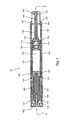
- FIG. 1is a longitudinal cross-sectional view of an automatic injector according to the invention
- FIG. 2is an enlarged, longitudinal cross-sectional view of the activation end of the automatic injector of FIG. 1 ;
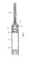
- FIG. 3is a longitudinal cross-sectional view of an assembled chamber, seal structure, and needle assembly of the injector of FIG. 1 ;
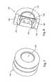
- FIG. 4is a longitudinal cross-sectional view of the seal structure and needle assembly of FIG. 3 ;
- FIGS. 5-8are lateral, longitudinal cross-sectional, perspective, and perspective cross-sectional views, respectively, of the seal structure of FIGS. 1 , 3 , and 4 ;
- FIGS. 9 and 10are longitudinal and enlarged, partial longitudinal cross-sectional views of the assembled chamber, seal structure, and needle assembly of the injector of FIG. 1 ;
- FIG. 11is a longitudinal cross-sectional view of another embodiment of an automatic injector according to the invention.
- FIG. 12is a longitudinal cross-sectional view of another embodiment of an assembled chamber, seal structure, and needle assembly of the injector of FIG. 11 ;
- FIG. 13is a longitudinal cross-sectional view of the assembled seal structure and needle assembly of FIG. 12 ;
- FIGS. 14 and 15are longitudinal and enlarged, partial longitudinal cross-sectional views of the assembled chamber, seal structure, and needle assembly of the injector of FIG. 11 ;
- FIG. 16is another longitudinal cross-sectional view of the seal structure and needle support of FIGS. 11-15 ;
- FIGS. 17-20are various perspective views of seal structures porous members, and needle assemblies according to the invention.
- the inventionis directed to automatic injectors that can accommodate and deliver a small, precise amount of a therapeutic agent.
- the automatic injectorsinclude a thin or flat porous member that carries thereon and/or therein the therapeutic agent.
- the thin or flat porous member with the therapeutic agent thereon and/or thereinresults in a shorter, more compact injection device because most, if not all, of the space needed for either (1) a second, dry compartment common in wet/dry automatic injectors or (2) the various types of known generally cylindrically-shaped scaffolds, substrates, sponges, cell structures, and tubular networks used to hold therapeutic agents in known injectors is unnecessary.
- the inventionis not limited to any one type of automatic injector.
- the inventionmay include a nose activated auto-injector, as described, for example, in U.S. Pat. No. 5,354,286, the disclosure of which is incorporated by reference.
- the inventionmay alternatively include a push button type auto-injector, where the user removes an end cap and presses a button to trigger the injection process as described, for example, in U.S. Pat. No. 6,641,561, the disclosure of which is also incorporated by reference.
- FIG. 1shows an embodiment of an automatic injector that can be used in connection with the invention.
- Automatic injector 10has a needle end 12 and an activation end 14 .
- the devicehas an outer body or housing 100 having an in-turned shoulder 101 .
- Located within the interior of outer body 100is a cartridge holder 102 .
- Cartridge holder 102has a shoulder 104 that fits against seat 105 of in-turned shoulder 101 .
- Cartridge holder 102also has a forward end portion 106 that is tapered to form a small circular aperture.
- Received within cartridge holder 102is a cartridge assembly 103 .
- the overall length of cartridge assembly 103is completely contained within cartridge holder 102 .
- Cartridge assembly 103has a chamber 120 that is preferably a hollow cylinder with either a smooth cylindrical interior surface or smooth interior side walls.
- Chamber 120has a first compartment 121 and, optionally, a much smaller second compartment 122 .
- the liquid injection solution or componentis located within first compartment 121 .
- a seal structure 130engages the interior surface or side walls of chamber 120 to seal the liquid injection solution in first compartment 121 and prevent seepage of the liquid injection solution into the optional second compartment 122 prior to activation of the injector device.
- a needle assembly 140is mounted to the forward end of chamber 120 to inject the therapeutic agent into a user upon activation of the injector.
- the forward end portion of chamber 120has an annular groove 123 formed therein for attachment of needle assembly 140 .
- Needle assembly 140has a crimp clamp 142 that is mechanically rolled into annular groove 123 to permanently secure and seal the needle assembly to the chamber.
- Needle assembly 140also includes a funnel-shaped needle support 141 , which can be made of a resilient plastic material or a metal with a rubber seal. Needle support 141 forms a sealed fluid channel from chamber 120 to needle 144 .
- a rubber needle sheath 145surrounds needle 144 and receives the narrow end of needle support 141 .
- outer body 100also includes a stored energy assembly 150 .
- the stored energy assemblycan be any conventional type known in the art, such as the forward end activating device disclosed in U.S. Pat. No. 3,712,301, the disclosure of which is incorporated by reference.
- the stored energy assemblymay employ a charge of compressed gas.
- stored energy assembly 150has an inner sleeve 151 and an outer sleeve 152 .
- Inner sleeve 151has an out-turned flange 153 and an end wall 154 .
- Out-turned flange 153fits up against the end of cartridge holder 102 when the stored energy assembly is inserted into outer body 100 .
- the length of outer sleeve 152is slightly less than that of inner sleeve 151 in order to leave space between the wall of outer sleeve 152 and flange 153 of inner sleeve 151 .
- Stored energy assembly 150also has a collet 160 that fits within out-turned flange 153 of inner sleeve 151 .
- the collethas a body portion 161 and a head portion 162 .
- the diameter of head portion 162is larger than body portion 161 and is generally slightly smaller than that of a plunger 163 .
- a coil spring 164is positioned over collet body portion 161 and abuts head portion 162 at one end and abuts the inner face of end wall 154 of inner sleeve 151 at the other end.
- FIG. 2shows activation end 14 of the automatic injector of FIG. 1 .
- Collet 160has four equally-spaced, longitudinally extending spring fingers 165 terminating in frusto-conical, locking detent heads 166 . These locking detent heads maintain collet 160 and inner sleeve 151 in an assembled position with a coil spring 167 compressed there between.
- detent heads 166are cammed inwardly by engaging the periphery of the end wall 154 opening so they can be passed through that opening, whereupon the bases of detent heads 166 come to rest on retaining surface 168 of end wall 154 to retain collet 160 and inner sleeve 151 in assembled condition with coil spring 167 compressed there between.
- the rear planar surface of the inner sleevecan be advantageously overlaid with a metal washer providing a guide and a holding flange to surround the opening.
- Outer sleeve 152has a closed end 170 with a central aperture from which a frusto-conical surface 171 extends. Surface 171 is sized and shaped to cooperate with frusto-conical detent heads 166 to cam the heads radially inward.
- the outer sleeve 152is provided with a circumferential locking rib 173 that fits in an annular groove 174 in outer body 100 to retain the stored energy assembly in position in the outer body.
- the length of outer sleeve 152is slightly less than that of inner sleeve 151 in order to leave space between the inner wall of outer sleeve 152 and flange 153 of inner sleeve 151 . This allows the two sleeves to move relative to each other to cam frusto-conical detent heads 166 inwardly during operation of the device.
- Safety pin assembly 175has a cylindrical sleeve 176 sized to fit over the end portion of outer sleeve 152 .
- a safety pin 177extends inwardly from the center of safety pin assembly 175 into the opening formed by the inner portions of detent heads 166 to prevent inward movement of the detent heads.
- Safety pin assembly 175is provided internally with a plurality of spacer abutments 178 to assure proper positioning of the cap on outer sleeve 152 .
- safety pin assembly 175is manually pulled off the rear end of the injector, thus removing pin 177 from between fingers 165 .
- Needle end 12 of injector 10is then pressed against an injection site.
- a telescoping actiontakes place between outer body 100 and cartridge holder 102 .
- This telescoping actioncauses the sleeves of the stored energy assembly to telescope, which causes surfaces 171 of outer sleeve 152 to engage the sloping surface 179 of detent heads 166 .
- Coil spring 167is now free to release its stored energy. This moves collet 160 forward to effect an injection operation.
- FIG. 3shows an assembly of needle assembly 140 and chamber 120 .
- chamber 120has a first compartment 121 and a significantly smaller second compartment 122 separated by seal structure 130 .
- Liquid injection solutionis stored in first compartment 121 .
- Seal structure 130engages the interior surface or side walls of chamber 120 to seal first compartment 121 from second compartment 122 , thus preventing any liquid injection solution from entering second compartment 122 .
- Adjacent seal structure 130is a thin or flat porous member 180 .
- Therapeutic agent 185is disposed on a surface of porous member 180 , which is positioned adjacent seal structure 130 . The therapeutic agent may alternatively or additionally be disposed within the pores of the porous member.
- FIG. 4shows seal structure 130 and needle assembly 140 .
- Seal structure 130has an outer seal 190 , an internal rigid member 191 , and a movable sealing plug 192 .
- Outer seal 190 and internal rigid member 191securingly engage each other using a combination of notched recesses 195 and extending shoulders 196 .
- outer seal 190 and internal rigid member 191may be secured together using bonding techniques known in the art or may be formed as an integral component.
- Internal rigid member 191may also be formed from two rigid bodies (e.g., two halves) that are annularly welded or bonded together.
- Internal rigid member 191has a by-pass channel 193 which creates at least one flow path. When plug 192 is moved from its location as shown in FIG. 4 to by-pass area 194 , by-pass channel 193 becomes a flow path such that a liquid component can flow through both seal structure 130 and porous member 180 , dissolving therapeutic agent 185 .
- FIGS. 5-8show seal structure 130 and porous member 180 with a therapeutic agent 185 disposed on a surface of the porous member 180 .
- Porous member 180is held in place between internal rigid member 191 and shoulder 196 of outer seal 190 and may be welded or bonded to rigid member 191 .
- the porous membercan be secured between those two rigid bodies.
- Therapeutic agent 185is carried on the surface of porous member 180 that faces away from internal rigid member 191 (that is, on the front side of the porous member).
- the therapeutic agentcan be disposed on the surface facing the rigid member or on both surfaces of the porous member.
- the therapeutic agentcan be located within the plurality of pores or holes in the porous member or within the pores/holes and on one or both of the surfaces of the porous member.
- FIGS. 9 and 10show the assembly of chamber 120 , seal structure 130 , and needle assembly 140 .
- Chamber 120contains seal structure 130 , which has an outer seal 190 and an internal rigid member 191 .
- Outer seal 190forms an annular seal with the inner surface of chamber 120 to prevent liquid from seeping around the seal structure.
- Porous member 180which contains therapeutic agent 185 , is held in place between internal rigid member 191 and shoulder 196 of outer seal 190 and may be welded or bonded to rigid member 191 .
- the forward end portion of chamber 120has an annular groove 123 formed therein about which needle assembly 140 is mounted.
- Needle assembly 140preferably includes a needle support 141 , which includes at least one crimp clamp 142 . Crimp clamp 142 is mechanically rolled into groove 123 to secure and seal needle assembly 140 to chamber 120 .
- FIG. 11shows another embodiment of an automatic injector that can be used in connection with the invention.
- Automatic injector 200has a needle end 210 and an activation end 211 .
- the devicehas an outer body or housing 212 that has an in-turned shoulder 213 .
- Located within the interior of outer body 212is a cartridge holder 214 .
- Cartridge holder 214has a shoulder 216 which fits against seat 217 of in-turned shoulder 213 .
- Cartridge holder 214also has a forward end portion 218 that is tapered to form a small circular aperture.
- Received within cartridge holder 214is a cartridge assembly 215 .
- the overall length of cartridge assembly 215is completely contained within cartridge holder 214 .
- Cartridge assembly 215has a chamber 220 that is preferably a hollow cylinder with either a smooth cylindrical inner surface or smooth interior side walls.
- chamber 220has a single compartment 221 that can contain a liquid injection solution or component.
- a seal structure 230engages the inner surface or interior side walls of chamber 220 to seal compartment 221 and prevent seepage of the liquid injection solution prior to activation of the injector device.
- a needle assembly 240mounts to chamber 220 to inject the therapeutic agent upon activation of the injector device.
- the forward end portion of chamber 220has an annular groove 223 formed therein for attachment of needle assembly 240 .
- Needle assembly 240includes a funnel-shaped needle support 241 that has a crimp clamp 242 mechanically rolled into annular groove 223 to permanently secure and seal the needle assembly to the chamber.
- Needle support 241can be made of a resilient plastic material or a metal with a rubber seal. Needle support 241 forms a sealed fluid channel from chamber 220 to needle 244 .
- a rubber needle sheath 245surrounds needle 244 and receives the narrow end of needle support 241 .
- outer body 212includes a stored energy assembly 250 .
- the stored energy assemblycan be any conventional type known in the art, such as the forward end activating device disclosed in U.S. Pat. No. 3,712,301.
- the stored energy assemblymay employ a charge of compressed gas.
- stored energy assembly 250has an inner sleeve 251 and an outer sleeve 252 .
- Inner sleeve 251has an out-turned flange 253 and an end wall 254 .
- Out-turned flange 253fits up against the end of cartridge holder 214 when the stored energy assembly is inserted into outer body 212 .
- the length of outer sleeve 252is slightly less than that of inner sleeve 251 in order to leave space between the wall of outer sleeve 252 and flange 253 of inner sleeve 251 .
- Stored energy assembly 250also has a collet 260 that fits within out-turned flange 253 of inner sleeve 251 .
- the collethas a body portion 261 and a head portion 262 .
- the diameter of head portion 262is larger than body portion 261 and is generally slightly smaller than that of a plunger 263 .
- a coil spring 264is positioned over collet body 261 and abuts head portion 262 at one end and abuts the inner face of end wall 254 of inner sleeve 251 at the other.
- seal structure 130is located in the main, large diameter portion of chamber 120
- seal structure 230is alternatively located in a neck portion 257 of chamber 220 .
- FIG. 12shows an assembly of chamber 220 , seal structure 230 , and needle assembly 240 of automatic injector 200 .
- the chamberhas neck portion 257 , which has an annular groove 223 .
- Seal structure 230engages the inner surface or interior side walls of neck portion 257 and is adjacent annular groove 223 .
- Therapeutic agent 285is disposed on porous member 280 , which is located on seal structure 230 .
- the seal structureseals and prevents any liquid stored in compartment 221 from contacting the therapeutic agent prior to activation of the automatic injector.
- FIG. 13shows seal structure 230 and needle assembly 240 .
- Seal structure 230has an outer seal 290 , an internal rigid member 291 , and a movable sealing plug 292 .
- Outer seal 290includes at least one side flange 295 .
- Seal structure 230is secured to needle assemble 240 by fitting side flange 295 into crimp clamp 242 .
- Seal structure 230also includes thin or flat porous member 280 , which contains therapeutic agent 285 . Porous member 280 is held in place between outer seal 290 and needle support 241 and may be welded or bonded to rigid member 291 .
- the porous membermay be secured in place between the outer seal and the internal rigid member and, in those embodiments where the internal rigid member is formed from two rigid bodies (e.g., two halves) that are annularly welded or bonded together, the porous member may be secured between those two rigid bodies.
- Internal rigid member 291has a by-pass channel 293 which creates at least one flow path. When plug 292 is moved from its location as shown in FIG. 13 to by-pass area 294 , by-pass channel 293 opens a flow path that allows the liquid component to flow through both seal structure 130 and porous member 280 .
- FIGS. 14 and 15show the assembly of chamber 220 , seal structure 230 , and needle assembly 240 .
- Chamber 220has neck portion 257 and annular groove 223 .
- Seal structure 230is located in neck portion 257 and has at least one side flange 295 .
- seal structure 130 of injector 100does not have a side flange.
- Needle assembly 240mounts to chamber 220 by rolling crimp clamp 242 into groove 223 , further securing side flange 295 between chamber 220 and needle assembly 240 .
- seal structure 230which has an outer seal 290 and an internal rigid member 291 .
- Outer seal 290includes side flange 295 .
- Seal structure 230is temporarily held in position between chamber 220 and needle assemble 240 when annular ridge member 296 is press fit to the flange of chamber 220 , thereby securing flange 295 between chamber 220 and needle assemble 240 .
- the lower portion of clamp 242is rolled into groove 223 of chamber 220 securing flange 295 between chamber 220 and needle assembly 240 .
- porous member 280which contains therapeutic agent 285 , is ultrasonically welded to ridge member 291 .
- FIG. 16shows seal structure 230 and needle assembly 240 (without chamber 220 and clamp 242 , for clarity).
- Seal structure 230has outer seal 290 , internal rigid member 291 , and movable sealing plug 292 .
- Outer seal 290includes at least one side flange 295
- internal rigid member 291has by-pass channel 293 such that movement of plug 292 to by-pass area 294 creates at least one flow path through by-pass channel 293 .
- porous member 280Positioned between seal structure 230 and needle assembly 240 and possibly attached to rigid member 291 is porous member 280 , which contains therapeutic agent 285 .
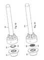
- FIGS. 17 and 18each show a method of assembling a thin or flat porous member, a seal structure, and a needle assembly.
- FIG. 17shows porous member 380 , which carries a therapeutic agent (not shown), secured to needle support 341 of a needle assembly 340 . Seal structure 330 is then secured to needle assembly 340 .
- FIG. 18shows porous member 480 , which carries therapeutic agent 485 , secured to seal structure 430 .
- the combined porous member and seal structureare then secured to the needle assembly.
- the porous membercan be secured to the seal structure or needle support by any means known in the art. In certain preferred embodiments, the porous member is secured by sonic welding.
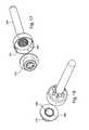
- FIGS. 19 and 20each show a method in which a therapeutic agent is applied to a thin or flat porous member.
- FIG. 19shows a seal structure 530 , a porous member 580 , and a needle assembly 540 .
- therapeutic agent 585is applied to the surface of porous member 580 that faces needle assembly 540 (i.e., the front surface).
- FIG. 20shows a seal structure 630 , a porous member 680 , and a needle assembly 640 .
- the therapeutic agentis applied such that it fills the pores of porous member 680 .
- the therapeutic agentcan be applied to (1) the surface of porous member 580 that faces the seal structure (i.e., the rear surface), (2) both surfaces of the porous member, or (3) either or both surfaces and within the pores of the porous member.
- the porous memberis operative to carry a therapeutic agent and release the therapeutic agent into a liquid component flowing through the porous member.
- the porous membercan be made out of any type of medically-appropriate material that can be made very thin or flat and have pores there through.
- the porous membercan be fabricated from metallic, ceramic, or polymeric materials, or combinations thereof. Suitable metallic materials include alloys such as stainless steel.
- Suitable ceramic materialsinclude, but are not limited to, oxides, carbides, and nitrides of the transition elements such as titanium oxides, hafnium oxides, iridium oxides, chromium oxides, aluminum oxides, and zirconium oxides. Silicon based materials, such as silica, may also be used.
- Suitable polymeric materials for forming the porous memberinclude, but are not limited to, isobutylene-based polymers, polystyrene-based polymers, polyacrylates and polyacrylate derivatives, vinyl acetate-based polymers and its copolymers, polyurethane and its copolymers, silicone and its copolymers, ethylene vinyl-acetate, polyethylene terephtalate, thermoplastic elastomers, polyvinyl chloride, polyolefins, cellulosics, polyamides, polyesters, polysulfones, polytetrafluorethylenes, polycarbonates, acrylonitrile butadiene styrene copolymers, acrylics, polylactic acid, polyglycolic acid, polycaprolactone, polylactic acid-polyethylene oxide copolymers, cellulose, collagens, and chitins.
- polymers that are useful as materials for forming the porous memberinclude, without limitation, dacron polyester, poly(ethylene terephthalate), polycarbonate, polymethylmethacrylate, polypropylene, polyalkylene oxalates, polyvinylchloride, polyurethanes, polysiloxanes, nylons, poly(dimethyl siloxane), polycyanoacrylates, polyphosphazenes, poly(amino acids), ethylene glycol I dimethacrylate, poly(methyl methacrylate), poly(2-hydroxyethyl methacrylate), polytetrafluoroethylene poly(HEMA), polyhydroxyalkanoates, polytetrafluorethylene, polycarbonate, poly(glycolide-lactide) co-polymer, polylactic acid, poly( ⁇ -caprolactone), poly( ⁇ -hydroxybutyrate), polydioxanone, poly( ⁇ -ethyl glutamate), polyiminocarbonates, poly(ortho ester), polyanhydr
- the porous memberis the shape of a thin or flat disc or membrane as shown in FIGS. 17-20 , which shows the porous member having a thin profile or minimal thickness (measured in the longitudinal direction of the interior chamber).
- Representative thicknesses for porous members of the inventionrange from about 0.005 inches (0.13 mm) to about 0.012 inches (0.30 mm) for polymeric materials and from about 0.010 inches (0.25 mm) to about 0.020 inches (0.51 mm) for metallic membranes.
- the diameter/width of a representative porous member(measured in the lateral direction of the interior chamber) is about 0.30 inches (7.62 mm), so the ratio of porous membrane diameter/width to thickness ranges from about 15:1 to 60:1.
- the thickness of the porous member, and its volume for that mattercan be considered negligible with respect to providing space in the longitudinal direction of and within a chamber in an automatic injector, wherein the term “negligible” as used herein is defined as being so small or unimportant as to warrant little or no attention.
- Advantages of the thin or flat therapeutic-agent-carrying porous members of the inventioninclude (1) requiring little if any additional space within an automatic injector; (2) greater versatility in placing and securing the porous member within the automatic injector than in known injectors having a dry compartment and/or using scaffolds, substrates, sponges, cell structures, and tubular networks; and (3) more rapid mixing of the liquid component with the therapeutic agent than in known injectors.
- the porous membercomprises a plurality of pores.
- the porescan be of different sizes or shapes.
- the porescan be interconnected or separate.
- the porescan also be distributed randomly or in a pattern.
- the size of the poresdepends on the type of therapeutic agent used.
- the poresshould be large enough to allow the liquid injection solution and the therapeutic agent to pass through.
- the average width or diameter of the poresranges from about 0.02 microns to about 5 microns. Pores can be formed in the porous member by any method known in the art, such as sand blasting, drilling, laser etching, or chemical etching.
- Preferred porous membersinclude without limitation thin or flat metal discs with a plurality of pores therein, thin or flat filters such as ceramic or metallic filters, and thin or flat discs or membranes made of polymeric material.
- Therapeutic agents used with porous members of the inventionpreferably include, but are not limited to, anti-asthmatics including beta-agonists such as salbutamol, levalbuterol, formoterol, fenoterol, salmeterol, bambuterol, brocaterol, clenbuterol, terbutalin, tulobuterol, epinephrin, isoprenalin, and hexoprenalin.
- beta-agonistssuch as salbutamol, levalbuterol, formoterol, fenoterol, salmeterol, bambuterol, brocaterol, clenbuterol, terbutalin, tulobuterol, epinephrin, isoprenalin, and hexoprenalin.
- anti-angiogenesis factorsantibodies
- antigenspolysaccharides: growth factors
- hormonesincluding insulin, glucogen, parathyroid and pituitary hormones, calcitonin, vasopressin, renin, prolactin, growth hormones, thyroid stimulating hormone, corticotrophin, follicle stimulating hormone, luteinizing hormone, and chorionic gonadotropins
- enzymesincluding soybean trypsin inhibitor, lysozyme, catalase, tumor angiogenesis factor, cartilage factor, transferases, hydrolases, lysases, isomerases, proteases, ligases and oxidoreductases such as esterases, phosphatases, glycosidases, and peptidases
- enzyme inhibitorssuch as leupeptin, antipain, chymostatin and pepstatin
- drugssuch as steroids, anti-cancer drugs, or antibiotics.
- the amount of therapeutic agent disposed in and/or on the porous memberdepends on the therapeutic agent used. In many cases, the appropriate amount of therapeutic agent is less than or equal to about 25 mg.
- the inventionis also directed to a method of assembling an automatic injector, which includes filling a chamber with a liquid component and inserting a seal structure in the chamber.
- inserting the seal structure into the chamberforms first and second compartments in the chamber.
- a second compartmentis not formed.
- the seal structurehas a first position that seals the liquid component in the chamber (or first compartment) and a second position that creates a flow path through the seal structure from the chamber to a needle assembly (or from the first compartment to the second compartment and then to the needle assembly).
- the methodfurther includes (1) applying a therapeutic agent to a thin or flat porous member, (2) securing the porous member at or after the end of the flow path, (3) mounting a needle assembly onto the chamber to dispense the therapeutic agent mixed with the liquid component, and (4) providing a housing to carry the injection device components.
- the therapeutic agentcan be applied to a surface of the porous member that faces the needle assembly and/or a surface that faces the seal structure.
- the therapeutic agentalternatively or additionally can be applied such that at least some, most, or all of the pores of the porous member are at least partially filled with the therapeutic agent.
- the porous membercan be secured to the seal structure or the needle assembly. Note that the order of the above method steps can be varied. For example, applying the therapeutic agent and securing the porous member may occur before insertion of the seal structure or the filling of the chamber with the liquid component.
- automatic injectors of the inventionhave been described herein with respect to the medical treatment of humans, they are not limited to such use.
- automatic injectors of the inventionmay be alternatively used in connection with the treatment of animals and related scientific research thereof (for example, the injectors can be used to inject zoo animals, farm animals, or laboratory animals).
- Automatic injectors of the inventionmay also be alternatively used in connection with agriculture, horticulture, or forestry and related scientific research thereof (for example, the injector can be used to inject fruit, vegetables, trees, and/or other types of plant life).
Landscapes
- Health & Medical Sciences (AREA)
- Life Sciences & Earth Sciences (AREA)
- Engineering & Computer Science (AREA)
- Veterinary Medicine (AREA)
- Public Health (AREA)
- General Health & Medical Sciences (AREA)
- Animal Behavior & Ethology (AREA)
- Biomedical Technology (AREA)
- Hematology (AREA)
- Heart & Thoracic Surgery (AREA)
- Anesthesiology (AREA)
- Vascular Medicine (AREA)
- Bioinformatics & Cheminformatics (AREA)
- Pharmacology & Pharmacy (AREA)
- Chemical & Material Sciences (AREA)
- Pulmonology (AREA)
- Medicinal Chemistry (AREA)
- Nuclear Medicine, Radiotherapy & Molecular Imaging (AREA)
- Chemical Kinetics & Catalysis (AREA)
- Organic Chemistry (AREA)
- General Chemical & Material Sciences (AREA)
- Infusion, Injection, And Reservoir Apparatuses (AREA)
- Acyclic And Carbocyclic Compounds In Medicinal Compositions (AREA)
- Medical Preparation Storing Or Oral Administration Devices (AREA)
- Medicinal Preparation (AREA)
- Materials For Medical Uses (AREA)
- Medicines That Contain Protein Lipid Enzymes And Other Medicines (AREA)
Abstract
Description
Claims (51)
Priority Applications (1)
| Application Number | Priority Date | Filing Date | Title |
|---|---|---|---|
| US12/116,437US8057427B2 (en) | 2007-05-09 | 2008-05-07 | Drug delivery system with a small amount of a therapeutic agent |
Applications Claiming Priority (2)
| Application Number | Priority Date | Filing Date | Title |
|---|---|---|---|
| US92859407P | 2007-05-09 | 2007-05-09 | |
| US12/116,437US8057427B2 (en) | 2007-05-09 | 2008-05-07 | Drug delivery system with a small amount of a therapeutic agent |
Publications (2)
| Publication Number | Publication Date |
|---|---|
| US20080281271A1 US20080281271A1 (en) | 2008-11-13 |
| US8057427B2true US8057427B2 (en) | 2011-11-15 |
Family
ID=39970189
Family Applications (1)
| Application Number | Title | Priority Date | Filing Date |
|---|---|---|---|
| US12/116,437Active2028-08-12US8057427B2 (en) | 2007-05-09 | 2008-05-07 | Drug delivery system with a small amount of a therapeutic agent |
Country Status (15)
| Country | Link |
|---|---|
| US (1) | US8057427B2 (en) |
| EP (1) | EP2144648B1 (en) |
| JP (6) | JP5674460B2 (en) |
| AU (1) | AU2008251840B2 (en) |
| CA (1) | CA2686012A1 (en) |
| CY (1) | CY1116998T1 (en) |
| DK (1) | DK2144648T3 (en) |
| ES (1) | ES2557936T3 (en) |
| HU (1) | HUE025850T2 (en) |
| IL (2) | IL201909A (en) |
| PL (1) | PL2144648T3 (en) |
| PT (1) | PT2144648E (en) |
| SI (1) | SI2144648T1 (en) |
| TW (1) | TWI542373B (en) |
| WO (1) | WO2008140737A2 (en) |
Cited By (32)
| Publication number | Priority date | Publication date | Assignee | Title |
|---|---|---|---|---|
| US8945063B2 (en) | 2009-03-20 | 2015-02-03 | Antares Pharma, Inc. | Hazardous agent injection system |
| WO2015142874A1 (en)* | 2014-03-18 | 2015-09-24 | Mcmahon Douglas F | Compact kit for injecting liquid medication |
| US9144648B2 (en) | 2006-05-03 | 2015-09-29 | Antares Pharma, Inc. | Injector with adjustable dosing |
| US9180259B2 (en) | 2005-01-24 | 2015-11-10 | Antares Pharma, Inc. | Prefilled syringe jet injector |
| US9220660B2 (en) | 2011-07-15 | 2015-12-29 | Antares Pharma, Inc. | Liquid-transfer adapter beveled spike |
| US9333309B2 (en) | 2002-02-11 | 2016-05-10 | Antares Pharma, Inc. | Intradermal injector |
| US9345839B2 (en) | 2011-12-08 | 2016-05-24 | Unitract Syringe Pty Ltd | Accurate dose control mechanisms and drug delivery syringes |
| US9364611B2 (en) | 2012-05-07 | 2016-06-14 | Antares Pharma, Inc. | Needle assisted jet injection device having reduced trigger force |
| US9393367B2 (en) | 2013-03-12 | 2016-07-19 | Antares Pharma, Inc. | Prefilled syringes and kits thereof |
| US9446195B2 (en) | 2011-07-15 | 2016-09-20 | Antares Pharma, Inc. | Injection device with cammed ram assembly |
| US9486583B2 (en) | 2012-03-06 | 2016-11-08 | Antares Pharma, Inc. | Prefilled syringe with breakaway force feature |
| US9561333B2 (en) | 2008-08-05 | 2017-02-07 | Antares Pharma, Inc. | Multiple dosage injector |
| US9707354B2 (en) | 2013-03-11 | 2017-07-18 | Antares Pharma, Inc. | Multiple dosage injector with rack and pinion dosage system |
| US9744302B2 (en) | 2013-02-11 | 2017-08-29 | Antares Pharma, Inc. | Needle assisted jet injection device having reduced trigger force |
| US9808582B2 (en) | 2006-05-03 | 2017-11-07 | Antares Pharma, Inc. | Two-stage reconstituting injector |
| US9867949B2 (en) | 2008-03-10 | 2018-01-16 | Antares Pharma, Inc. | Injector safety device |
| US9907911B2 (en) | 2014-08-18 | 2018-03-06 | Windgap Medical, Inc. | Portable drug mixing and delivery device and associated methods |
| US9907910B2 (en) | 2013-03-15 | 2018-03-06 | Windgap Medical, Inc. | Portable drug mixing and delivery device and associated methods |
| US9950125B2 (en) | 2012-04-06 | 2018-04-24 | Antares Pharma, Inc. | Needle assisted jet injection administration of testosterone compositions |
| US10195361B2 (en) | 2013-03-15 | 2019-02-05 | Windgap Medical, Inc. | Portable drug mixing and delivery system and method |
| US10213556B2 (en) | 2011-12-08 | 2019-02-26 | Unl Holdings Llc | Accurate dose control mechanisms and drug delivery syringes |
| US10220147B2 (en) | 2015-08-13 | 2019-03-05 | Windgap Medical, Inc. | Mixing and injection device with sterility features |
| US10328211B2 (en) | 2011-12-08 | 2019-06-25 | Unl Holdings Llc | Automatic self-dispensing accurate dose drug delivery syringes |
| US10350364B2 (en) | 2009-11-11 | 2019-07-16 | Windgap Medical, Inc. | Portable Drug Mixing and Delivery Device and Associated Methods |
| US10391262B2 (en) | 2014-03-18 | 2019-08-27 | Windgap Medical, Inc. | Removable actuating cap for use with an auto-injector assembly |
| US10569017B2 (en) | 2013-03-15 | 2020-02-25 | Windgap Medical, Inc. | Portable drug mixing and delivery device and associated methods |
| US10952709B2 (en) | 2014-04-04 | 2021-03-23 | Hyperbranch Medical Technology, Inc. | Extended tip spray applicator for two-component surgical sealant, and methods of use thereof |
| US11027056B2 (en) | 2018-02-01 | 2021-06-08 | Allergy Medical, Llc | Compact kit for injecting liquid medication |
| US11116903B2 (en) | 2014-08-18 | 2021-09-14 | Windgap Medical, Inc | Compression seal for use with a liquid component storage vial of an auto-injector |
| US11246842B2 (en) | 2014-12-18 | 2022-02-15 | Windgap Medical, Inc. | Method and compositions for dissolving or solubilizing therapeutic agents |
| US12239823B2 (en) | 2013-12-18 | 2025-03-04 | Windgap Medical, Inc. | Drug mixing and delivery system and method |
| US12239822B2 (en) | 2013-03-15 | 2025-03-04 | Windgap Medical, Inc. | Portable drug mixing and delivery device and associated methods |
Families Citing this family (42)
| Publication number | Priority date | Publication date | Assignee | Title |
|---|---|---|---|---|
| US20090038701A1 (en) | 2006-01-17 | 2009-02-12 | Baxter International Inc. | Device, system and method for mixing |
| CA2632608C (en)* | 2006-01-17 | 2013-08-06 | Baxter International Inc. | Device, system and method for mixing |
| US8057427B2 (en)* | 2007-05-09 | 2011-11-15 | Meridian Medical Technologies, Inc. | Drug delivery system with a small amount of a therapeutic agent |
| WO2010105836A1 (en)* | 2009-03-19 | 2010-09-23 | Csl Behring Gmbh | Connecting unit having valve that is opened by the fluid pressure |
| US20100246316A1 (en)* | 2009-03-31 | 2010-09-30 | Baxter International Inc. | Dispenser, kit and mixing adapter |
| GB2469672B (en)* | 2009-04-23 | 2013-09-25 | Medical House Ltd | Improved autoinjector |
| WO2010127146A1 (en)* | 2009-04-29 | 2010-11-04 | Abbott Biotechnology Ltd | Automatic injection device |
| AR076717A1 (en)* | 2009-06-02 | 2011-06-29 | Sanofi Aventis Deutschland | MEDICATED MODULE FOR A PHARMACO DELIVERY DEVICE |
| TW201109058A (en) | 2009-06-02 | 2011-03-16 | Sanofi Aventis Deutschland | Medicated module with needle guard |
| TW201103594A (en) | 2009-06-02 | 2011-02-01 | Sanofi Aventis Deutschland | Medicated module with premix medicament |
| US8641661B2 (en) | 2010-01-05 | 2014-02-04 | Baxter International Inc. | Mixing system, kit and mixer adapter |
| CA2726566A1 (en)* | 2010-01-11 | 2011-07-11 | Baxter International Inc. | Pipette system, pipette tip assembly and kit |
| CA2790050C (en)* | 2010-03-23 | 2021-04-20 | Hyperbranch Medical Technology, Inc. | Disposable syringe applicators for multi-component formulations, and methods of use thereof |
| CA2818670A1 (en) | 2010-11-29 | 2012-06-07 | Sanofi-Aventis Deutschland Gmbh | Medicated module with automatic reservoir engagement |
| EP2489381A1 (en) | 2011-02-18 | 2012-08-22 | Sanofi-Aventis Deutschland GmbH | Auto-injector |
| EP2489380A1 (en) | 2011-02-18 | 2012-08-22 | Sanofi-Aventis Deutschland GmbH | Injection device |
| EP2489389A1 (en) | 2011-02-18 | 2012-08-22 | Sanofi-Aventis Deutschland GmbH | Detent mechanism |
| EP2489382A1 (en) | 2011-02-18 | 2012-08-22 | Sanofi-Aventis Deutschland GmbH | Auto-injector |
| EP2489387A1 (en) | 2011-02-18 | 2012-08-22 | Sanofi-Aventis Deutschland GmbH | Auto-injector |
| EP2489384A1 (en) | 2011-02-18 | 2012-08-22 | Sanofi-Aventis Deutschland GmbH | Auto-injector |
| EP2489388A1 (en) | 2011-02-18 | 2012-08-22 | Sanofi-Aventis Deutschland GmbH | Auto-injector |
| EP2489385A1 (en) | 2011-02-18 | 2012-08-22 | Sanofi-Aventis Deutschland GmbH | Auto-injector |
| EP2489386A1 (en) | 2011-02-18 | 2012-08-22 | Sanofi-Aventis Deutschland GmbH | Auto-injector |
| DK2723426T3 (en)* | 2011-06-21 | 2019-11-04 | Brent Buchine | AUTOMATIC MIXING AND DELIVERY SYSTEM |
| WO2013175136A1 (en) | 2012-05-25 | 2013-11-28 | Aptar France Sas | Autoinjector |
| WO2013175144A1 (en) | 2012-05-25 | 2013-11-28 | Aptar France Sas | Autoinjector |
| CN104394909B (en) | 2012-05-25 | 2017-03-29 | 阿普塔尔法国简易股份公司 | Automatic injector |
| FR2990868B1 (en)* | 2012-05-25 | 2015-10-02 | Aptar France Sas | autoinjector |
| FR2990864B1 (en)* | 2012-05-25 | 2015-05-15 | Valois Sas | autoinjector |
| EP2854901B1 (en) | 2012-05-25 | 2019-10-02 | Aptar France SAS | Autoinjector comprising a time delay device having a planetary gear set for delaying the retraction of the needle |
| US9931467B2 (en) | 2012-05-25 | 2018-04-03 | Aptar France Sas | Autoinjector |
| EP3308814B1 (en) | 2012-09-27 | 2020-11-18 | APTAR France SAS | Autoinjector |
| WO2015105937A1 (en)* | 2014-01-09 | 2015-07-16 | Valeritas, Inc. | Piston |
| KR101538380B1 (en)* | 2015-05-14 | 2015-07-22 | 주식회사 신한세라믹 | Syringe ceramic-filter and manufacturing method of thereof |
| EP3355968B1 (en)* | 2015-10-02 | 2021-05-12 | F. Hoffmann-La Roche AG | Multi chamber syringe unit |
| KR102251644B1 (en)* | 2019-05-08 | 2021-05-13 | 김용현 | Drug mixing device, drug mixing kit comprising the same and method for manufacturing the same |
| JP1703752S (en) | 2021-05-18 | 2025-01-07 | Syringe | |
| JP1703754S (en) | 2021-05-18 | 2025-01-07 | Syringe | |
| JP1703751S (en) | 2021-05-18 | 2025-01-07 | Syringe | |
| JP1703753S (en) | 2021-05-18 | 2025-01-07 | Syringe | |
| USD995768S1 (en) | 2021-11-18 | 2023-08-15 | Chugai Seiyaku Kabushiki Kaisha | Syringe barrel |
| KR20250005335A (en) | 2022-04-26 | 2025-01-09 | 추가이 세이야쿠 가부시키가이샤 | Syringe with built-in filter containing pharmaceutical preparation |
Citations (13)
| Publication number | Priority date | Publication date | Assignee | Title |
|---|---|---|---|---|
| US3592245A (en)* | 1968-09-24 | 1971-07-13 | American Home Prod | Universal dispensing device for intravenous medications |
| US5330426A (en) | 1992-08-13 | 1994-07-19 | Science Incorporated | Mixing and delivery syringe assembly |
| US5411480A (en) | 1989-06-16 | 1995-05-02 | Science Incorporated | Fluid delivery apparatus |
| US5779676A (en) | 1995-10-11 | 1998-07-14 | Science Incorporated | Fluid delivery device with bolus injection site |
| US20030068354A1 (en)* | 2001-10-05 | 2003-04-10 | Oscar-Werner Reif | Genetic vaccination device and process for forming an injection therefor |
| US20030105423A1 (en) | 1999-05-21 | 2003-06-05 | Mallinckrodt Inc. | Suspension device and method |
| US6641561B1 (en)* | 2000-10-10 | 2003-11-04 | Meridian Medical Technologies, Inc. | Drug delivery device |
| US20040097874A1 (en) | 2000-10-10 | 2004-05-20 | Meridian Medical Technologies, Inc. | Separation assembly for drug delivery device |
| US20040260242A1 (en) | 1999-05-21 | 2004-12-23 | Mallinckrodt Inc. | Suspension device and method |
| US20060034929A1 (en) | 2001-12-27 | 2006-02-16 | Brubaker Michael J | Sustained release drug delivery devices with prefabricated permeable plugs |
| US20060129122A1 (en) | 2004-12-06 | 2006-06-15 | Wyrick Ronald E | Method and apparatus for delivering epinephrine |
| US20070256688A1 (en)* | 2006-04-21 | 2007-11-08 | Aradigm Corporation | Mechanical single dose intrapulmonary drug delivery devices |
| US20080294100A1 (en)* | 2005-11-21 | 2008-11-27 | Cambridge Biostability Limited | Pharmaceutical Device For the Administration of Substrates to Patients |
Family Cites Families (6)
| Publication number | Priority date | Publication date | Assignee | Title |
|---|---|---|---|---|
| US6012A (en)* | 1849-01-09 | Lithographing co | ||
| US5360410A (en)* | 1991-01-16 | 1994-11-01 | Senetek Plc | Safety syringe for mixing two-component medicaments |
| EP1709984A3 (en)* | 2000-10-10 | 2006-10-18 | Meridian Medical Technologies, Inc. | Wet/dry automatic injector assembly |
| EP1347742A1 (en)* | 2001-01-03 | 2003-10-01 | Bausch & Lomb Incorporated | Sustained release drug delivery devices with prefabricated permeable plugs |
| AU2002332808C1 (en)* | 2002-09-03 | 2008-11-13 | Meridian Medical Technologies, Inc. | Drug delivery device |
| US8057427B2 (en)* | 2007-05-09 | 2011-11-15 | Meridian Medical Technologies, Inc. | Drug delivery system with a small amount of a therapeutic agent |
- 2008
- 2008-05-07USUS12/116,437patent/US8057427B2/enactiveActive
- 2008-05-08JPJP2010507459Apatent/JP5674460B2/enactiveActive
- 2008-05-08HUHUE08754254Apatent/HUE025850T2/enunknown
- 2008-05-08WOPCT/US2008/005896patent/WO2008140737A2/enactiveApplication Filing
- 2008-05-08ESES08754254.4Tpatent/ES2557936T3/enactiveActive
- 2008-05-08EPEP08754254.4Apatent/EP2144648B1/enactiveActive
- 2008-05-08SISI200831534Tpatent/SI2144648T1/enunknown
- 2008-05-08AUAU2008251840Apatent/AU2008251840B2/ennot_activeCeased
- 2008-05-08CACA002686012Apatent/CA2686012A1/ennot_activeAbandoned
- 2008-05-08PLPL08754254Tpatent/PL2144648T3/enunknown
- 2008-05-08DKDK08754254.4Tpatent/DK2144648T3/enactive
- 2008-05-08PTPT87542544Tpatent/PT2144648E/enunknown
- 2008-05-09TWTW097117324Apatent/TWI542373B/enactive
- 2009
- 2009-11-03ILIL201909Apatent/IL201909A/enactiveIP Right Grant
- 2013
- 2013-08-08ILIL227898Apatent/IL227898A/enactiveIP Right Grant
- 2014
- 2014-12-22JPJP2014258273Apatent/JP2015091345A/enactivePending
- 2015
- 2015-12-04CYCY20151101104Tpatent/CY1116998T1/enunknown
- 2017
- 2017-01-06JPJP2017000828Apatent/JP2017099903A/enactivePending
- 2018
- 2018-11-01JPJP2018206593Apatent/JP2019051338A/enactivePending
- 2020
- 2020-07-09JPJP2020118183Apatent/JP2020189102A/enactivePending
- 2022
- 2022-07-14JPJP2022113147Apatent/JP2022160456A/enactivePending
Patent Citations (13)
| Publication number | Priority date | Publication date | Assignee | Title |
|---|---|---|---|---|
| US3592245A (en)* | 1968-09-24 | 1971-07-13 | American Home Prod | Universal dispensing device for intravenous medications |
| US5411480A (en) | 1989-06-16 | 1995-05-02 | Science Incorporated | Fluid delivery apparatus |
| US5330426A (en) | 1992-08-13 | 1994-07-19 | Science Incorporated | Mixing and delivery syringe assembly |
| US5779676A (en) | 1995-10-11 | 1998-07-14 | Science Incorporated | Fluid delivery device with bolus injection site |
| US20040260242A1 (en) | 1999-05-21 | 2004-12-23 | Mallinckrodt Inc. | Suspension device and method |
| US20030105423A1 (en) | 1999-05-21 | 2003-06-05 | Mallinckrodt Inc. | Suspension device and method |
| US6641561B1 (en)* | 2000-10-10 | 2003-11-04 | Meridian Medical Technologies, Inc. | Drug delivery device |
| US20040097874A1 (en) | 2000-10-10 | 2004-05-20 | Meridian Medical Technologies, Inc. | Separation assembly for drug delivery device |
| US20030068354A1 (en)* | 2001-10-05 | 2003-04-10 | Oscar-Werner Reif | Genetic vaccination device and process for forming an injection therefor |
| US20060034929A1 (en) | 2001-12-27 | 2006-02-16 | Brubaker Michael J | Sustained release drug delivery devices with prefabricated permeable plugs |
| US20060129122A1 (en) | 2004-12-06 | 2006-06-15 | Wyrick Ronald E | Method and apparatus for delivering epinephrine |
| US20080294100A1 (en)* | 2005-11-21 | 2008-11-27 | Cambridge Biostability Limited | Pharmaceutical Device For the Administration of Substrates to Patients |
| US20070256688A1 (en)* | 2006-04-21 | 2007-11-08 | Aradigm Corporation | Mechanical single dose intrapulmonary drug delivery devices |
Cited By (76)
| Publication number | Priority date | Publication date | Assignee | Title |
|---|---|---|---|---|
| US9737670B2 (en) | 2002-02-11 | 2017-08-22 | Antares Pharma, Inc. | Intradermal injector |
| US9333309B2 (en) | 2002-02-11 | 2016-05-10 | Antares Pharma, Inc. | Intradermal injector |
| US9629959B2 (en) | 2005-01-24 | 2017-04-25 | Antares Pharma, Inc. | Prefilled syringe jet injector |
| US10478560B2 (en) | 2005-01-24 | 2019-11-19 | Antares Pharma, Inc. | Prefilled syringe injector |
| US9180259B2 (en) | 2005-01-24 | 2015-11-10 | Antares Pharma, Inc. | Prefilled syringe jet injector |
| US11446441B2 (en) | 2005-01-24 | 2022-09-20 | Antares Pharma, Inc. | Prefilled syringe injector |
| US11471600B2 (en) | 2006-05-03 | 2022-10-18 | Antares Pharma, Inc. | Injector with adjustable dosing |
| US11547808B2 (en) | 2006-05-03 | 2023-01-10 | Antares Pharma, Inc. | Two-stage reconstituting injector |
| US10688250B2 (en) | 2006-05-03 | 2020-06-23 | Antares Pharma, Inc. | Two-stage reconstituting injector |
| US10543316B2 (en) | 2006-05-03 | 2020-01-28 | Antares Pharma, Inc. | Injector with adjustable dosing |
| US9144648B2 (en) | 2006-05-03 | 2015-09-29 | Antares Pharma, Inc. | Injector with adjustable dosing |
| US9808582B2 (en) | 2006-05-03 | 2017-11-07 | Antares Pharma, Inc. | Two-stage reconstituting injector |
| US12121704B2 (en) | 2006-05-03 | 2024-10-22 | Antares Pharma, Inc. | Injector with adjustable dosing |
| US9867949B2 (en) | 2008-03-10 | 2018-01-16 | Antares Pharma, Inc. | Injector safety device |
| US10709844B2 (en) | 2008-03-10 | 2020-07-14 | Antares Pharma, Inc. | Injector safety device |
| US11684723B2 (en) | 2008-03-10 | 2023-06-27 | Antares Pharma, Inc. | Injector safety device |
| US9561333B2 (en) | 2008-08-05 | 2017-02-07 | Antares Pharma, Inc. | Multiple dosage injector |
| US10300212B2 (en) | 2008-08-05 | 2019-05-28 | Antares Pharma, Inc. | Multiple dosage injector |
| US11058824B2 (en) | 2008-08-05 | 2021-07-13 | Antares Pharma, Inc. | Multiple dosage injector |
| US12357642B2 (en) | 2009-03-20 | 2025-07-15 | Antares Pharma, Inc. | Hazardous agent injection system |
| US9750881B2 (en) | 2009-03-20 | 2017-09-05 | Antares Pharma, Inc. | Hazardous agent injection system |
| US8945063B2 (en) | 2009-03-20 | 2015-02-03 | Antares Pharma, Inc. | Hazardous agent injection system |
| US11497753B2 (en) | 2009-03-20 | 2022-11-15 | Antares Pharma, Inc. | Hazardous agent injection system |
| US10555954B2 (en) | 2009-03-20 | 2020-02-11 | Antares Pharma, Inc. | Hazardous agent injection system |
| US10350364B2 (en) | 2009-11-11 | 2019-07-16 | Windgap Medical, Inc. | Portable Drug Mixing and Delivery Device and Associated Methods |
| US12179007B2 (en) | 2011-07-15 | 2024-12-31 | Antares Pharma, Inc. | Injection device with cammed ram assembly |
| US10568809B2 (en) | 2011-07-15 | 2020-02-25 | Ferring B.V. | Liquid-transfer adapter beveled spike |
| US11185642B2 (en) | 2011-07-15 | 2021-11-30 | Antares Pharma, Inc. | Injection device with cammed ram assembly |
| US10279131B2 (en) | 2011-07-15 | 2019-05-07 | Antares Pharma, Inc. | Injection device with cammed RAM assembly |
| US9220660B2 (en) | 2011-07-15 | 2015-12-29 | Antares Pharma, Inc. | Liquid-transfer adapter beveled spike |
| US9446195B2 (en) | 2011-07-15 | 2016-09-20 | Antares Pharma, Inc. | Injection device with cammed ram assembly |
| US9345839B2 (en) | 2011-12-08 | 2016-05-24 | Unitract Syringe Pty Ltd | Accurate dose control mechanisms and drug delivery syringes |
| US10328211B2 (en) | 2011-12-08 | 2019-06-25 | Unl Holdings Llc | Automatic self-dispensing accurate dose drug delivery syringes |
| US10213556B2 (en) | 2011-12-08 | 2019-02-26 | Unl Holdings Llc | Accurate dose control mechanisms and drug delivery syringes |
| US9486583B2 (en) | 2012-03-06 | 2016-11-08 | Antares Pharma, Inc. | Prefilled syringe with breakaway force feature |
| US12409272B2 (en) | 2012-03-06 | 2025-09-09 | Antares Pharma, Inc. | Prefilled syringe with breakaway force feature |
| US11602597B2 (en) | 2012-03-06 | 2023-03-14 | Antares Pharma, Inc. | Prefilled syringe with breakaway force feature |
| US10478559B2 (en) | 2012-03-06 | 2019-11-19 | Antares Pharma, Inc. | Prefilled syringe with breakaway force feature |
| US11771646B2 (en) | 2012-04-06 | 2023-10-03 | Antares Pharma, Inc. | Needle assisted jet injection administration of testosterone compositions |
| US9950125B2 (en) | 2012-04-06 | 2018-04-24 | Antares Pharma, Inc. | Needle assisted jet injection administration of testosterone compositions |
| US10821072B2 (en) | 2012-04-06 | 2020-11-03 | Antares Pharma, Inc. | Needle assisted jet injection administration of testosterone compositions |
| US12220560B2 (en) | 2012-05-07 | 2025-02-11 | Antares Pharma, Inc. | Needle assisted injection device having reduced trigger force |
| US12171986B2 (en) | 2012-05-07 | 2024-12-24 | Antares Pharma, Inc. | Injection device with cammed ram assembly |
| US11446440B2 (en) | 2012-05-07 | 2022-09-20 | Antares Pharma, Inc. | Needle assisted injection device having reduced trigger force |
| US9364611B2 (en) | 2012-05-07 | 2016-06-14 | Antares Pharma, Inc. | Needle assisted jet injection device having reduced trigger force |
| US10905827B2 (en) | 2012-05-07 | 2021-02-02 | Antares Pharma, Inc. | Injection device with cammed ram assembly |
| US9364610B2 (en) | 2012-05-07 | 2016-06-14 | Antares Pharma, Inc. | Injection device with cammed ram assembly |
| US10357609B2 (en) | 2012-05-07 | 2019-07-23 | Antares Pharma, Inc. | Needle assisted jet injection device having reduced trigger force |
| US12318581B2 (en) | 2013-02-11 | 2025-06-03 | Antares Pharma, Inc. | Needle assisted injection device having reduced trigger force |
| US10881798B2 (en) | 2013-02-11 | 2021-01-05 | Antares Pharma, Inc. | Needle assisted injection device having reduced trigger force |
| US11813435B2 (en) | 2013-02-11 | 2023-11-14 | Antares Pharma, Inc. | Needle assisted injection device having reduced trigger force |
| US9744302B2 (en) | 2013-02-11 | 2017-08-29 | Antares Pharma, Inc. | Needle assisted jet injection device having reduced trigger force |
| US10610649B2 (en) | 2013-03-11 | 2020-04-07 | Antares Pharma, Inc. | Multiple dosage injector with rack and pinion dosage system |
| US9707354B2 (en) | 2013-03-11 | 2017-07-18 | Antares Pharma, Inc. | Multiple dosage injector with rack and pinion dosage system |
| US11628260B2 (en) | 2013-03-11 | 2023-04-18 | Antares Pharma, Inc. | Multiple dosage injector with rack and pinion dosage system |
| US10675400B2 (en) | 2013-03-12 | 2020-06-09 | Antares Pharma, Inc. | Prefilled syringes and kits thereof |
| US9393367B2 (en) | 2013-03-12 | 2016-07-19 | Antares Pharma, Inc. | Prefilled syringes and kits thereof |
| US12239822B2 (en) | 2013-03-15 | 2025-03-04 | Windgap Medical, Inc. | Portable drug mixing and delivery device and associated methods |
| US10569017B2 (en) | 2013-03-15 | 2020-02-25 | Windgap Medical, Inc. | Portable drug mixing and delivery device and associated methods |
| US9907910B2 (en) | 2013-03-15 | 2018-03-06 | Windgap Medical, Inc. | Portable drug mixing and delivery device and associated methods |
| US10195361B2 (en) | 2013-03-15 | 2019-02-05 | Windgap Medical, Inc. | Portable drug mixing and delivery system and method |
| US12239823B2 (en) | 2013-12-18 | 2025-03-04 | Windgap Medical, Inc. | Drug mixing and delivery system and method |
| US10391262B2 (en) | 2014-03-18 | 2019-08-27 | Windgap Medical, Inc. | Removable actuating cap for use with an auto-injector assembly |
| WO2015142874A1 (en)* | 2014-03-18 | 2015-09-24 | Mcmahon Douglas F | Compact kit for injecting liquid medication |
| US10952709B2 (en) | 2014-04-04 | 2021-03-23 | Hyperbranch Medical Technology, Inc. | Extended tip spray applicator for two-component surgical sealant, and methods of use thereof |
| US9907911B2 (en) | 2014-08-18 | 2018-03-06 | Windgap Medical, Inc. | Portable drug mixing and delivery device and associated methods |
| US9925335B2 (en) | 2014-08-18 | 2018-03-27 | Windgap Medical, Inc | Portable drug mixing and delivery device and associated methods |
| US11007320B2 (en) | 2014-08-18 | 2021-05-18 | Windgap Medical, Inc. | Portable drug mixing and delivery device and associated methods |
| US10537680B2 (en) | 2014-08-18 | 2020-01-21 | Windgap Medical, Inc. | Portable drug mixing and delivery device and associated methods |
| US9950115B2 (en) | 2014-08-18 | 2018-04-24 | Windgap Medical, Inc. | Portable drug mixing and delivery device and associated methods |
| US10300198B2 (en) | 2014-08-18 | 2019-05-28 | Windgap Medical, Inc. | Portable drug mixing and delivery device and associated methods |
| US11116903B2 (en) | 2014-08-18 | 2021-09-14 | Windgap Medical, Inc | Compression seal for use with a liquid component storage vial of an auto-injector |
| US10300199B2 (en) | 2014-08-18 | 2019-05-28 | Windgap Medical, Inc. | Portable drug mixing and delivery device and associated methods |
| US11246842B2 (en) | 2014-12-18 | 2022-02-15 | Windgap Medical, Inc. | Method and compositions for dissolving or solubilizing therapeutic agents |
| US10220147B2 (en) | 2015-08-13 | 2019-03-05 | Windgap Medical, Inc. | Mixing and injection device with sterility features |
| US11027056B2 (en) | 2018-02-01 | 2021-06-08 | Allergy Medical, Llc | Compact kit for injecting liquid medication |
Also Published As
| Publication number | Publication date |
|---|---|
| HUE025850T2 (en) | 2016-05-30 |
| JP2015091345A (en) | 2015-05-14 |
| ES2557936T3 (en) | 2016-01-29 |
| EP2144648A2 (en) | 2010-01-20 |
| JP2022160456A (en) | 2022-10-19 |
| JP5674460B2 (en) | 2015-02-25 |
| JP2010526584A (en) | 2010-08-05 |
| PL2144648T3 (en) | 2016-03-31 |
| TW200902108A (en) | 2009-01-16 |
| CA2686012A1 (en) | 2008-11-20 |
| JP2017099903A (en) | 2017-06-08 |
| IL201909A0 (en) | 2010-06-16 |
| IL201909A (en) | 2013-08-29 |
| AU2008251840B2 (en) | 2013-09-26 |
| EP2144648A4 (en) | 2014-08-13 |
| EP2144648B1 (en) | 2015-11-04 |
| WO2008140737A3 (en) | 2009-12-30 |
| IL227898A (en) | 2015-06-30 |
| DK2144648T3 (en) | 2015-11-23 |
| PT2144648E (en) | 2016-02-01 |
| JP2020189102A (en) | 2020-11-26 |
| WO2008140737A2 (en) | 2008-11-20 |
| TWI542373B (en) | 2016-07-21 |
| US20080281271A1 (en) | 2008-11-13 |
| JP2019051338A (en) | 2019-04-04 |
| AU2008251840A1 (en) | 2008-11-20 |
| IL227898A0 (en) | 2013-09-30 |
| CY1116998T1 (en) | 2017-04-05 |
| SI2144648T1 (en) | 2015-12-31 |
Similar Documents
| Publication | Publication Date | Title |
|---|---|---|
| US8057427B2 (en) | Drug delivery system with a small amount of a therapeutic agent | |
| US6641561B1 (en) | Drug delivery device | |
| AU2023219806A1 (en) | Wet/dry automatic injector assembly | |
| US7556614B2 (en) | Separation assembly for drug delivery device | |
| MXPA05002354A (en) | Drug delivery device. | |
| AU2022202966A1 (en) | Wet/dry automatic injector assembly | |
| IL151579A (en) | Drug delivery device |
Legal Events
| Date | Code | Title | Description |
|---|---|---|---|
| AS | Assignment | Owner name:MERIDIAN MEDICAL TECHNOLOGIES, INC., MARYLAND Free format text:ASSIGNMENT OF ASSIGNORS INTEREST;ASSIGNORS:GRIFFITHS, STEVEN M.;HILL, ROBERT L.;WANNARKA, GERALD L.;REEL/FRAME:021176/0766;SIGNING DATES FROM 20080606 TO 20080618 Owner name:MERIDIAN MEDICAL TECHNOLOGIES, INC., MARYLAND Free format text:ASSIGNMENT OF ASSIGNORS INTEREST;ASSIGNORS:GRIFFITHS, STEVEN M.;HILL, ROBERT L.;WANNARKA, GERALD L.;SIGNING DATES FROM 20080606 TO 20080618;REEL/FRAME:021176/0766 | |
| AS | Assignment | Owner name:CREDIT SUISSE, AS AGENT, NEW YORK Free format text:SECURITY AGREEMENT;ASSIGNOR:MERIDIAN MEDICAL TECHNOLOGIES, INC.;REEL/FRAME:022034/0922 Effective date:20081229 Owner name:CREDIT SUISSE, AS AGENT,NEW YORK Free format text:SECURITY AGREEMENT;ASSIGNOR:MERIDIAN MEDICAL TECHNOLOGIES, INC.;REEL/FRAME:022034/0922 Effective date:20081229 | |
| AS | Assignment | Owner name:CREDIT SUISSE AG,NEW YORK Free format text:RELEASE OF SECURITY INTEREST;ASSIGNOR:MERIDIAN MEDICAL TECHNOLOGIES, INC.;REEL/FRAME:024369/0032 Effective date:20100511 Owner name:CREDIT SUISSE AG, NEW YORK Free format text:RELEASE OF SECURITY INTEREST;ASSIGNOR:MERIDIAN MEDICAL TECHNOLOGIES, INC.;REEL/FRAME:024369/0032 Effective date:20100511 | |
| AS | Assignment | Owner name:CREDIT SUISSE AG,NEW YORK Free format text:SECURITY AGREEMENT;ASSIGNOR:MERIDIAN MEDICAL TECHNOLOGIES, INC.;REEL/FRAME:024379/0816 Effective date:20100511 Owner name:CREDIT SUISSE AG, NEW YORK Free format text:SECURITY AGREEMENT;ASSIGNOR:MERIDIAN MEDICAL TECHNOLOGIES, INC.;REEL/FRAME:024379/0816 Effective date:20100511 | |
| AS | Assignment | Owner name:MERIDIAN MEDICAL TECHNOLOGIES, INC., MARYLAND Free format text:RELEASE BY SECURED PARTY;ASSIGNOR:CREDIT SUISSE AG;REEL/FRAME:025741/0482 Effective date:20110131 | |
| STCF | Information on status: patent grant | Free format text:PATENTED CASE | |
| FPAY | Fee payment | Year of fee payment:4 | |
| MAFP | Maintenance fee payment | Free format text:PAYMENT OF MAINTENANCE FEE, 8TH YEAR, LARGE ENTITY (ORIGINAL EVENT CODE: M1552); ENTITY STATUS OF PATENT OWNER: LARGE ENTITY Year of fee payment:8 | |
| AS | Assignment | Owner name:MERIDIAN MEDICAL TECHNOLOGIES, LLC, MARYLAND Free format text:ENTITY CONVERSION;ASSIGNOR:MERIDIAN MEDICAL TECHNOLOGIES, INC.;REEL/FRAME:059727/0945 Effective date:20211231 | |
| AS | Assignment | Owner name:JPMORGAN CHASE BANK, N.A., AS COLLATERAL AGENT, ILLINOIS Free format text:SECURITY INTEREST;ASSIGNOR:MERIDIAN MEDICAL TECHNOLOGIES, LLC;REEL/FRAME:062089/0698 Effective date:20221212 | |
| MAFP | Maintenance fee payment | Free format text:PAYMENT OF MAINTENANCE FEE, 12TH YEAR, LARGE ENTITY (ORIGINAL EVENT CODE: M1553); ENTITY STATUS OF PATENT OWNER: LARGE ENTITY Year of fee payment:12 |