US8057410B2 - Semi-powered lower extremity exoskeleton - Google Patents
Semi-powered lower extremity exoskeletonDownload PDFInfo
- Publication number
- US8057410B2 US8057410B2US11/404,719US40471906AUS8057410B2US 8057410 B2US8057410 B2US 8057410B2US 40471906 AUS40471906 AUS 40471906AUS 8057410 B2US8057410 B2US 8057410B2
- Authority
- US
- United States
- Prior art keywords
- exoskeleton
- power unit
- person
- hydraulic
- flexion
- Prior art date
- Legal status (The legal status is an assumption and is not a legal conclusion. Google has not performed a legal analysis and makes no representation as to the accuracy of the status listed.)
- Active, expires
Links
- 210000003141lower extremityAnatomy0.000titleclaimsabstractdescription37
- 210000002414legAnatomy0.000claimsabstractdescription189
- 210000000689upper legAnatomy0.000claimsabstractdescription88
- 210000003127kneeAnatomy0.000claimsabstractdescription39
- 210000000629knee jointAnatomy0.000claimsabstractdescription37
- 210000002683footAnatomy0.000claimsdescription94
- 210000001624hipAnatomy0.000claimsdescription76
- 239000012530fluidSubstances0.000claimsdescription34
- 210000003423ankleAnatomy0.000claimsdescription28
- 125000004122cyclic groupChemical group0.000claimsdescription16
- 229920001971elastomerPolymers0.000claimsdescription14
- 238000012546transferMethods0.000claimsdescription14
- 239000000806elastomerSubstances0.000claimsdescription9
- 230000008878couplingEffects0.000claimsdescription8
- 238000010168coupling processMethods0.000claimsdescription8
- 238000005859coupling reactionMethods0.000claimsdescription8
- 230000006835compressionEffects0.000claimsdescription6
- 238000007906compressionMethods0.000claimsdescription6
- 230000007246mechanismEffects0.000claimsdescription6
- 238000000034methodMethods0.000claimsdescription6
- 238000003491arrayMethods0.000claimsdescription4
- 230000007935neutral effectEffects0.000claimsdescription4
- 230000005611electricityEffects0.000claimsdescription3
- 230000008859changeEffects0.000claimsdescription2
- 235000013305foodNutrition0.000claimsdescription2
- XLYOFNOQVPJJNP-UHFFFAOYSA-NwaterSubstancesOXLYOFNOQVPJJNP-UHFFFAOYSA-N0.000claimsdescription2
- 230000008929regenerationEffects0.000claims2
- 238000011069regeneration methodMethods0.000claims2
- 230000000284resting effectEffects0.000claims2
- 230000009194climbingEffects0.000abstractdescription9
- 230000008901benefitEffects0.000description3
- 238000013461designMethods0.000description3
- 230000000694effectsEffects0.000description3
- 238000011160researchMethods0.000description2
- HGCIXCUEYOPUTN-UHFFFAOYSA-NC1CC=CCC1Chemical compoundC1CC=CCC1HGCIXCUEYOPUTN-UHFFFAOYSA-N0.000description1
- 238000005452bendingMethods0.000description1
- 230000027455bindingEffects0.000description1
- 238000009739bindingMethods0.000description1
- 239000003990capacitorSubstances0.000description1
- 238000002485combustion reactionMethods0.000description1
- 230000003247decreasing effectEffects0.000description1
- 230000007123defenseEffects0.000description1
- 238000011161developmentMethods0.000description1
- 238000010586diagramMethods0.000description1
- 235000012489doughnutsNutrition0.000description1
- 239000013536elastomeric materialSubstances0.000description1
- 238000004146energy storageMethods0.000description1
- 239000000446fuelSubstances0.000description1
- 210000004394hip jointAnatomy0.000description1
- 238000007689inspectionMethods0.000description1
- 239000002184metalSubstances0.000description1
- 230000003278mimic effectEffects0.000description1
- 238000012986modificationMethods0.000description1
- 230000004048modificationEffects0.000description1
- -1surgical tubePolymers0.000description1
Images


Classifications
- A—HUMAN NECESSITIES
- A61—MEDICAL OR VETERINARY SCIENCE; HYGIENE
- A61H—PHYSICAL THERAPY APPARATUS, e.g. DEVICES FOR LOCATING OR STIMULATING REFLEX POINTS IN THE BODY; ARTIFICIAL RESPIRATION; MASSAGE; BATHING DEVICES FOR SPECIAL THERAPEUTIC OR HYGIENIC PURPOSES OR SPECIFIC PARTS OF THE BODY
- A61H3/00—Appliances for aiding patients or disabled persons to walk about
- A—HUMAN NECESSITIES
- A61—MEDICAL OR VETERINARY SCIENCE; HYGIENE
- A61H—PHYSICAL THERAPY APPARATUS, e.g. DEVICES FOR LOCATING OR STIMULATING REFLEX POINTS IN THE BODY; ARTIFICIAL RESPIRATION; MASSAGE; BATHING DEVICES FOR SPECIAL THERAPEUTIC OR HYGIENIC PURPOSES OR SPECIFIC PARTS OF THE BODY
- A61H1/00—Apparatus for passive exercising; Vibrating apparatus; Chiropractic devices, e.g. body impacting devices, external devices for briefly extending or aligning unbroken bones
- A61H1/02—Stretching or bending or torsioning apparatus for exercising
- A61H1/0237—Stretching or bending or torsioning apparatus for exercising for the lower limbs
- A61H1/024—Knee
- A—HUMAN NECESSITIES
- A61—MEDICAL OR VETERINARY SCIENCE; HYGIENE
- A61H—PHYSICAL THERAPY APPARATUS, e.g. DEVICES FOR LOCATING OR STIMULATING REFLEX POINTS IN THE BODY; ARTIFICIAL RESPIRATION; MASSAGE; BATHING DEVICES FOR SPECIAL THERAPEUTIC OR HYGIENIC PURPOSES OR SPECIFIC PARTS OF THE BODY
- A61H3/00—Appliances for aiding patients or disabled persons to walk about
- A61H3/008—Appliances for aiding patients or disabled persons to walk about using suspension devices for supporting the body in an upright walking or standing position, e.g. harnesses
- B—PERFORMING OPERATIONS; TRANSPORTING
- B25—HAND TOOLS; PORTABLE POWER-DRIVEN TOOLS; MANIPULATORS
- B25J—MANIPULATORS; CHAMBERS PROVIDED WITH MANIPULATION DEVICES
- B25J9/00—Programme-controlled manipulators
- B25J9/0006—Exoskeletons, i.e. resembling a human figure
- A—HUMAN NECESSITIES
- A61—MEDICAL OR VETERINARY SCIENCE; HYGIENE
- A61B—DIAGNOSIS; SURGERY; IDENTIFICATION
- A61B5/00—Measuring for diagnostic purposes; Identification of persons
- A61B5/103—Measuring devices for testing the shape, pattern, colour, size or movement of the body or parts thereof, for diagnostic purposes
- A61B5/1036—Measuring load distribution, e.g. podologic studies
- A61B5/1038—Measuring plantar pressure during gait
- A—HUMAN NECESSITIES
- A61—MEDICAL OR VETERINARY SCIENCE; HYGIENE
- A61B—DIAGNOSIS; SURGERY; IDENTIFICATION
- A61B5/00—Measuring for diagnostic purposes; Identification of persons
- A61B5/45—For evaluating or diagnosing the musculoskeletal system or teeth
- A61B5/4528—Joints
- A—HUMAN NECESSITIES
- A61—MEDICAL OR VETERINARY SCIENCE; HYGIENE
- A61F—FILTERS IMPLANTABLE INTO BLOOD VESSELS; PROSTHESES; DEVICES PROVIDING PATENCY TO, OR PREVENTING COLLAPSING OF, TUBULAR STRUCTURES OF THE BODY, e.g. STENTS; ORTHOPAEDIC, NURSING OR CONTRACEPTIVE DEVICES; FOMENTATION; TREATMENT OR PROTECTION OF EYES OR EARS; BANDAGES, DRESSINGS OR ABSORBENT PADS; FIRST-AID KITS
- A61F5/00—Orthopaedic methods or devices for non-surgical treatment of bones or joints; Nursing devices ; Anti-rape devices
- A61F5/01—Orthopaedic devices, e.g. long-term immobilising or pressure directing devices for treating broken or deformed bones such as splints, casts or braces
- A61F5/0102—Orthopaedic devices, e.g. long-term immobilising or pressure directing devices for treating broken or deformed bones such as splints, casts or braces specially adapted for correcting deformities of the limbs or for supporting them; Ortheses, e.g. with articulations
- A—HUMAN NECESSITIES
- A61—MEDICAL OR VETERINARY SCIENCE; HYGIENE
- A61H—PHYSICAL THERAPY APPARATUS, e.g. DEVICES FOR LOCATING OR STIMULATING REFLEX POINTS IN THE BODY; ARTIFICIAL RESPIRATION; MASSAGE; BATHING DEVICES FOR SPECIAL THERAPEUTIC OR HYGIENIC PURPOSES OR SPECIFIC PARTS OF THE BODY
- A61H1/00—Apparatus for passive exercising; Vibrating apparatus; Chiropractic devices, e.g. body impacting devices, external devices for briefly extending or aligning unbroken bones
- A61H1/02—Stretching or bending or torsioning apparatus for exercising
- A61H1/0237—Stretching or bending or torsioning apparatus for exercising for the lower limbs
- A—HUMAN NECESSITIES
- A61—MEDICAL OR VETERINARY SCIENCE; HYGIENE
- A61H—PHYSICAL THERAPY APPARATUS, e.g. DEVICES FOR LOCATING OR STIMULATING REFLEX POINTS IN THE BODY; ARTIFICIAL RESPIRATION; MASSAGE; BATHING DEVICES FOR SPECIAL THERAPEUTIC OR HYGIENIC PURPOSES OR SPECIFIC PARTS OF THE BODY
- A61H2201/00—Characteristics of apparatus not provided for in the preceding codes
- A61H2201/12—Driving means
- A61H2201/1238—Driving means with hydraulic or pneumatic drive
- A—HUMAN NECESSITIES
- A61—MEDICAL OR VETERINARY SCIENCE; HYGIENE
- A61H—PHYSICAL THERAPY APPARATUS, e.g. DEVICES FOR LOCATING OR STIMULATING REFLEX POINTS IN THE BODY; ARTIFICIAL RESPIRATION; MASSAGE; BATHING DEVICES FOR SPECIAL THERAPEUTIC OR HYGIENIC PURPOSES OR SPECIFIC PARTS OF THE BODY
- A61H2201/00—Characteristics of apparatus not provided for in the preceding codes
- A61H2201/16—Physical interface with patient
- A61H2201/1602—Physical interface with patient kind of interface, e.g. head rest, knee support or lumbar support
- A61H2201/1614—Shoulder, e.g. for neck stretching
- A61H2201/1616—Holding means therefor
- A—HUMAN NECESSITIES
- A61—MEDICAL OR VETERINARY SCIENCE; HYGIENE
- A61H—PHYSICAL THERAPY APPARATUS, e.g. DEVICES FOR LOCATING OR STIMULATING REFLEX POINTS IN THE BODY; ARTIFICIAL RESPIRATION; MASSAGE; BATHING DEVICES FOR SPECIAL THERAPEUTIC OR HYGIENIC PURPOSES OR SPECIFIC PARTS OF THE BODY
- A61H2201/00—Characteristics of apparatus not provided for in the preceding codes
- A61H2201/16—Physical interface with patient
- A61H2201/1602—Physical interface with patient kind of interface, e.g. head rest, knee support or lumbar support
- A61H2201/1619—Thorax
- A61H2201/1621—Holding means therefor
- A—HUMAN NECESSITIES
- A61—MEDICAL OR VETERINARY SCIENCE; HYGIENE
- A61H—PHYSICAL THERAPY APPARATUS, e.g. DEVICES FOR LOCATING OR STIMULATING REFLEX POINTS IN THE BODY; ARTIFICIAL RESPIRATION; MASSAGE; BATHING DEVICES FOR SPECIAL THERAPEUTIC OR HYGIENIC PURPOSES OR SPECIFIC PARTS OF THE BODY
- A61H2201/00—Characteristics of apparatus not provided for in the preceding codes
- A61H2201/16—Physical interface with patient
- A61H2201/1602—Physical interface with patient kind of interface, e.g. head rest, knee support or lumbar support
- A61H2201/1623—Back
- A—HUMAN NECESSITIES
- A61—MEDICAL OR VETERINARY SCIENCE; HYGIENE
- A61H—PHYSICAL THERAPY APPARATUS, e.g. DEVICES FOR LOCATING OR STIMULATING REFLEX POINTS IN THE BODY; ARTIFICIAL RESPIRATION; MASSAGE; BATHING DEVICES FOR SPECIAL THERAPEUTIC OR HYGIENIC PURPOSES OR SPECIFIC PARTS OF THE BODY
- A61H2201/00—Characteristics of apparatus not provided for in the preceding codes
- A61H2201/16—Physical interface with patient
- A61H2201/1602—Physical interface with patient kind of interface, e.g. head rest, knee support or lumbar support
- A61H2201/1628—Pelvis
- A61H2201/163—Pelvis holding means therefor
- A—HUMAN NECESSITIES
- A61—MEDICAL OR VETERINARY SCIENCE; HYGIENE
- A61H—PHYSICAL THERAPY APPARATUS, e.g. DEVICES FOR LOCATING OR STIMULATING REFLEX POINTS IN THE BODY; ARTIFICIAL RESPIRATION; MASSAGE; BATHING DEVICES FOR SPECIAL THERAPEUTIC OR HYGIENIC PURPOSES OR SPECIFIC PARTS OF THE BODY
- A61H2201/00—Characteristics of apparatus not provided for in the preceding codes
- A61H2201/16—Physical interface with patient
- A61H2201/1602—Physical interface with patient kind of interface, e.g. head rest, knee support or lumbar support
- A61H2201/1635—Hand or arm, e.g. handle
- A—HUMAN NECESSITIES
- A61—MEDICAL OR VETERINARY SCIENCE; HYGIENE
- A61H—PHYSICAL THERAPY APPARATUS, e.g. DEVICES FOR LOCATING OR STIMULATING REFLEX POINTS IN THE BODY; ARTIFICIAL RESPIRATION; MASSAGE; BATHING DEVICES FOR SPECIAL THERAPEUTIC OR HYGIENIC PURPOSES OR SPECIFIC PARTS OF THE BODY
- A61H2201/00—Characteristics of apparatus not provided for in the preceding codes
- A61H2201/16—Physical interface with patient
- A61H2201/1602—Physical interface with patient kind of interface, e.g. head rest, knee support or lumbar support
- A61H2201/164—Feet or leg, e.g. pedal
- A61H2201/1642—Holding means therefor
- A—HUMAN NECESSITIES
- A61—MEDICAL OR VETERINARY SCIENCE; HYGIENE
- A61H—PHYSICAL THERAPY APPARATUS, e.g. DEVICES FOR LOCATING OR STIMULATING REFLEX POINTS IN THE BODY; ARTIFICIAL RESPIRATION; MASSAGE; BATHING DEVICES FOR SPECIAL THERAPEUTIC OR HYGIENIC PURPOSES OR SPECIFIC PARTS OF THE BODY
- A61H2201/00—Characteristics of apparatus not provided for in the preceding codes
- A61H2201/16—Physical interface with patient
- A61H2201/1602—Physical interface with patient kind of interface, e.g. head rest, knee support or lumbar support
- A61H2201/165—Wearable interfaces
- A—HUMAN NECESSITIES
- A61—MEDICAL OR VETERINARY SCIENCE; HYGIENE
- A61H—PHYSICAL THERAPY APPARATUS, e.g. DEVICES FOR LOCATING OR STIMULATING REFLEX POINTS IN THE BODY; ARTIFICIAL RESPIRATION; MASSAGE; BATHING DEVICES FOR SPECIAL THERAPEUTIC OR HYGIENIC PURPOSES OR SPECIFIC PARTS OF THE BODY
- A61H2201/00—Characteristics of apparatus not provided for in the preceding codes
- A61H2201/16—Physical interface with patient
- A61H2201/1657—Movement of interface, i.e. force application means
- A61H2201/1676—Pivoting
- A—HUMAN NECESSITIES
- A61—MEDICAL OR VETERINARY SCIENCE; HYGIENE
- A61H—PHYSICAL THERAPY APPARATUS, e.g. DEVICES FOR LOCATING OR STIMULATING REFLEX POINTS IN THE BODY; ARTIFICIAL RESPIRATION; MASSAGE; BATHING DEVICES FOR SPECIAL THERAPEUTIC OR HYGIENIC PURPOSES OR SPECIFIC PARTS OF THE BODY
- A61H2201/00—Characteristics of apparatus not provided for in the preceding codes
- A61H2201/50—Control means thereof
- A61H2201/5058—Sensors or detectors
- A61H2201/5061—Force sensors
Definitions
- the present inventionrelates generally to the field of lower extremity exoskeletons and more specifically to the field of semi-powered lower extremity exoskeletons.
- the lower extremity exoskeletoncomprises two leg supports connectable to person's lower limbs and configured to rest on the ground during their stance phase.
- Each leg supportcomprises a thigh link and a shank link; a knee joint configured to allow flexion and extension between the shank link and the thigh link.
- the lower extremity exoskeletonfurther comprises an exoskeleton trunk connectable to the person's upper body.
- the exoskeleton trunkis connectable to the thigh links of the leg supports allowing for the flexion and extension between the leg supports and the exoskeleton trunk.
- Two torque generatorsare coupled to each of the knee joints.
- a power unitcapable of providing power, is coupled to the torque generators.
- the power unitinjects power into the respective torque generator thereby extending the respective knee angle.
- the power unitdoes not inject any power to the respective torque generator, but without dissipating any stored power in said power unit, it forces the torque generator to resist flexion of the respective knee joint.
- the power unitdoes not inject any power to the respective torque generator, but without dissipating any stored power in said power unit, it forces the torque generator to minimize its resistance to knee flexion and extension.
- FIG. 1is a front view perspective drawing in accordance with an embodiment of the present invention.
- FIG. 2is a rear view perspective drawing of the embodiment of FIG. 1 .
- FIG. 3is a perspective drawing in accordance with an embodiment of the present invention.
- FIG. 4is a perspective drawing in accordance with an embodiment of the present invention.
- FIG. 5is a perspective drawing in accordance with an embodiment of the present invention.
- FIG. 6is a perspective drawing in accordance with an embodiment of the present invention.
- FIG. 7is a perspective drawing in accordance with an embodiment of the present invention.
- FIG. 8is a perspective drawing in accordance with an embodiment of the present invention.
- FIG. 9is a perspective drawing in accordance with an embodiment of the present invention.
- FIG. 10is a partial view of the invention of the embodiment of FIG. 9 .
- FIG. 11is a partial view of the invention of the embodiment of FIG. 9 .
- FIG. 12is a perspective drawing in accordance with an embodiment of the present invention.
- FIG. 13is a perspective drawing in accordance with an embodiment of the invention.
- FIG. 14is a perspective drawing in accordance with an embodiment of the exoskeleton foot.
- FIG. 15is a perspective drawing in accordance with an embodiment of the exoskeleton foot.
- FIG. 16is a perspective drawing in accordance with an embodiment of the exoskeleton foot.
- FIG. 17is a perspective drawing in accordance with an embodiment of the exoskeleton foot.
- FIG. 18is a perspective drawing in accordance with an embodiment of the exoskeleton foot.
- FIG. 19is a perspective drawing in accordance with an embodiment of the exoskeleton foot.
- FIG. 20is a drawing in accordance with an embodiment of the invention.
- FIG. 21is a perspective drawing in accordance with an embodiment of the invention.
- FIG. 22is a drawing in accordance with an embodiment of the exoskeleton foot.
- FIG. 23is a drawing in accordance with an embodiment of the exoskeleton foot.
- FIG. 24is a drawing in accordance with an embodiment of the exoskeleton foot.
- FIG. 25is a drawing in accordance with an embodiment of the exoskeleton foot.
- FIG. 26is a drawing in accordance with an embodiment of the exoskeleton foot.
- FIG. 27is a perspective drawing in accordance with an embodiment of the invention.
- FIG. 28is a drawing representing an embodiment of the exoskeleton power unit.
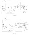
- FIG. 29is a drawing representing an embodiment of the exoskeleton hydraulic circuitry.
- FIG. 30is a drawing representing an embodiment of the exoskeleton hydraulic circuitry.
- FIG. 31is a drawing representing an embodiment of the exoskeleton hydraulic circuitry.
- FIG. 32is a drawing representing an embodiment of the exoskeleton hydraulic circuitry.
- FIG. 33is a drawing representing an embodiment of the exoskeleton hydraulic circuitry.
- FIG. 34is a drawing representing an embodiment of the exoskeleton hydraulic circuitry.
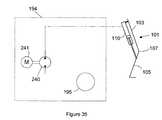
- FIG. 35is a drawing representing an embodiment of the exoskeleton hydraulic circuitry.
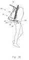
- FIG. 36is a drawing representing an embodiment of the exoskeleton stowed in a vertical position when the exoskeleton is not in use but needs to be carried.
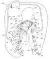
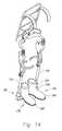
- FIG. 1 and FIG. 2are perspective drawings illustrating a lower extremity exoskeleton 100 wearable by a person 187 .
- Lower extremity exoskeleton 100comprises two leg supports 101 and 102 , which are configured to be connectable to the person's lower limbs and configured to rest on the ground during their stance phase.
- the leg supportscomprise thigh links 103 and 104 and shank links 105 and 106 .
- Two knee joints 107 and 108are configured to allow flexion and extension between the shank and thigh of the leg supports (shown by arrows 213 and 214 respectively).
- Lower extremity exoskeleton 100further comprises an exoskeleton trunk 109 .
- Exoskeleton trunk 109comprises a human interface device 150 .
- Exoskeleton trunk 109is configurable to be coupled to the person's upper body through human interface device 150 .
- the person's upper bodymeans any location above the thighs.
- Exoskeleton trunk 109is rotatably connectable to thigh links 103 and 104 of leg supports 101 and 102 at hip flexion-extension joints 125 and 126 , allowing for the hip flexion and extension rotations (shown by arrows 215 and 216 respectively) of leg supports 101 and 102 about hip flexion-extension axes 151 and 152 respectively.
- a power unit 201capable of providing power, is coupled to torque generators 110 and 111 , and is configured to operate in at least two modes for each torque generator 110 and 111 .
- power unit 201injects power into torque generator 110 to extend the knee angle of leg support 101 , which is defined between shank link 105 and thigh link 103 of the leg support 101 .
- a cyclic knee motionhere is defined as a motion where the initial and the final configurations of a shank link ( 105 or 106 ) and its corresponding thigh link ( 103 or 104 ) with respect to each other are nearly identical.
- a cyclic knee motionis a motion where the leg support is not in contact with the ground and the initial and the final configurations of the corresponding shank link and thigh link with respect to each other are nearly identical.
- a cyclic knee motionis a motion where the leg support is in contact with the ground and the initial and the final configurations of the corresponding shank link and thigh link with respect to each other are nearly identical.
- power unit 201further operates in a third mode for each torque generators 110 and 111 .
- power unit 201when power unit 201 operates in its third mode with respect to torque generator 110 , the energy required for the flexion and extension between shank link 105 and thigh link 103 of leg support 101 over a cyclic knee motion is provided by person 187 , and power unit 201 causes torque generator 110 to minimize its resistance to knee flexion and extension.
- lower extremity exoskeleton 100comprises at least one foot sensor per leg support.
- Leg support 101includes foot sensor 160 , which produces a stance signal 219 representing the force on the bottom of wearer's corresponding foot.
- leg support 102includes foot sensor 161 , which produces a stance signal 220 representing the force on the bottom of the other wearer's foot.
- Power unit 201controls torque generators 110 and 111 as a function of stance signals 219 and 220 .
- Stance signals 219 and 220detect if the wearer's leg is in stance phase or in a swing phase.
- stance signals 219 and 220represent the magnitude of the force on the bottom of wearer's feet. During swing phase, stance signals 219 and 220 will detect small or zero magnitude for the force on the bottom of the wearer's feet.
- lower extremity exoskeleton 100includes at least one angle sensor per leg support.
- Leg support 101comprises an angle sensor 243 which produces an angle signal 245 representing the angle of knee joint 107 .
- leg support 102comprises an angle sensor 244 which produces an angle signal 246 representing the angle of knee joint 108 .
- Power unit 201controls torque generators 110 and 111 as a function of angle signals 245 and 246 .
- Angle signals 245 and 246detect if leg supports 101 and 102 are postured (i.e., bent) to climb stairs or a slope. In some embodiments of angle sensors, angle signals 245 and 246 represent the magnitude of the joint angles for knee joints 107 and 108 .
- power unit 201operates in its first mode with respect to torque generator 110 , when stance signal 219 indicates the presence of a force on the bottom of corresponding human foot (i.e., leg support 101 is in a stance phase) and angle signal 245 indicates that leg support 101 is either bent or postured to climb stairs or a slope.
- torque generator 111Power unit 201 operates in its first mode with respect to torque generator 111 , when stance signal 220 indicates the presence of a force on the bottom of corresponding human foot (i.e., leg support 102 is in a stance phase) and angle signal 246 indicates that leg support 102 is either bent or postured to climb stairs or a slope.
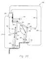
- the knee joint angleshown as the angle “A” for knee joint 108 in FIG. 20
- the preset valuewas chosen to be 135°. In another embodiment the preset value was chosen to be 165°.
- power unit 201operates in the second mode with respect to torque generator 110 , when stance signal 219 indicates the presence of a force on the bottom of corresponding human foot (i.e., leg support 101 is in a stance phase) and angle sensor 245 detects that leg support 101 is neither bent nor postured to climb stairs or a slope.
- torque generator 111Power unit 201 operates in second mode with respect to torque generator 111 , when stance signal 220 indicates the presence of a force on the bottom of corresponding human foot (i.e., leg support 102 is in a stance phase) and angle signal 246 indicates that leg support 102 is neither bent nor postured to climb stairs or a slope.
- power unit 201operates in the third mode with respect to torque generator 110 , when stance signal 219 detects that leg support 101 is in a swing phase. The same is true for torque generators 111 . Power unit 201 operates in third mode with respect to torque generator 111 , when stance signal 220 detects that leg support 102 is in a swing phase.
- power unit 201is configurable to inject power into torque generators 110 and 111 during the stance phase of leg supports 101 and 102 and when they are bent or postured to climb stairs or slopes.
- power unit 201is configurable such that the energy required for the flexion and extension between the shank link and the thigh link of a leg support over a cyclic knee motion can be provided by the person.
- power unit 201is configurable such that the energy required for the flexion and extension between the shank link and the thigh link of a leg support over a cyclic knee motion can be provided by the person.
- leg supports 101 and 102comprise shank holding devices 137 and 138 that couple person 187 to leg supports 101 and 102 .
- torque generators 110 and 111each comprise a hydraulic torque generator.
- Power unit 201is capable of providing hydraulic power for torque generators 110 and 111 and among other components, as shown in FIG. 28 , includes hydraulic circuitry 194 configured to be connectable to hydraulic torque generators 110 and 111 .
- Hydraulic circuitry 194 in power unit 201modulates the hydraulic fluid flow to hydraulic torque generators 110 and 111 .
- Hydraulic torque generators 110 and 111comprise of any hydraulic torque generator or combination of torque generators capable of converting pressurized hydraulic fluid into force or torque.
- hydraulic torque generators 110 and 111include, without limitation, linear hydraulic piston-cylinders, rotary hydraulic actuators, rack-and-pinion-type rotary actuators and rotary hydraulic vane type actuators where pressurized hydraulic fluid, by pushing against moving surfaces, generate force or torque.
- An illustration of an exoskeleton utilizing rotary hydraulic systemsis shown in FIG. 13 .
- torque generators 110 and 111 and the power unit 201are a combination of electrical devices possibly including a clutch.
- the torque generatorcould be a ball screw and the power unit could be a combination of a clutch (to minimize the resistance to flexion and extension during swing) and an electric motor (to inject energy).
- FIG. 29shows an embodiment of the hydraulic circuitry 194 .
- Hydraulic circuitry 194comprises a hydraulic pump 240 . In operation when power unit 201 operates in its first mode with respect to torque generator 110 , motor 241 turns hydraulic pump 240 and hydraulic pump 240 injects hydraulic fluid into torque generator 110 causing knee joint of leg support 101 to extend. Power unit 201 further comprises power storage component 238 (as shown in FIG. 28 ) such as batteries and capacitors to provide power for motor 241 and other components such as sensors and electronic components. Hydraulic circuitry 194 further comprises a pump isolating valve 239 . In operation, when power unit 201 operates in its first mode with respect to torque generator 110 , pump isolating valve 239 connects hydraulic pump 240 to torque generator 110 . Hydraulic circuitry 194 further comprises an actuated flow restricting valve 200 .
- leg support 101when leg support 101 is in a stance phase and is bent or positioned to climb stairs or a slope, power unit 201 operates in its first mode with respect to torque generator 110 .
- actuated flow restricting valve 200is shut and pump isolating valve 239 is open. This allows hydraulic pump 240 to inject hydraulic fluid to hydraulic torque generator 110 from a source of hydraulic fluid (e.g. hydraulic reservoir 195 in FIG. 29 ) causing knee joint 107 to extend.
- a source of hydraulic fluide.g. hydraulic reservoir 195 in FIG. 29
- power unit 201when leg support 101 is in a stance phase, but is not bent or positioned to climb stairs or a slope, power unit 201 operates in its second mode with respect to torque generator 110 .
- pump isolating valve 239disconnects the fluid flow between hydraulic pump 240 and torque generator 110 and actuated flow restricting valve 200 restricts the fluid flow from torque generator 110 . This causes knee joint 107 to resist flexion.
- leg support 101when leg support 101 is in a swing phase, power unit 201 operates in its third mode.
- actuated flow restricting valve 200is open and allows for the minimum resistance hydraulic fluid flow between hydraulic torque generator 110 and a source of fluid (e.g., hydraulic reservoir 195 ). This allows leg support 101 to be moved with little or no resistance.
- hydraulic reservoir 195is used to represent the source of fluid.
- source of fluidrefers to either a hydraulic reservoir or the other chamber in a double acting hydraulic cylinder with rods on both ends.
- Actuated flow restricting valve 200comprises any valve or combination of valves capable of performing the indicated functions.
- Examples of actuated flow restricting valve 200include, without limitation, flow control valve, pressure control valve, actuated needle valves, solenoid valves and on-off valve.
- Motor 241comprises any device or combination of devices capable of driving hydraulic pump 240 .
- Examples of motor 241include, without limitation, electric motors, including, without limitation, AC (alternating current) motors, brush-type DC (direct current) motors, brushless DC motors, electronically commutated motors (ECMs), stepping motors, and combinations thereof.
- motor 241is an internal combustion device where a fuel is combusted to create motion.
- FIG. 30represents another embodiment of the hydraulic circuitry 194 .
- This embodimentis similar to embodiment of FIG. 29 but a hydraulic check valve (one way valve) 199 has been added that connects a source of hydraulic fluid (e.g., hydraulic reservoir 195 ) to torque generator 110 .
- a source of hydraulic fluide.g., hydraulic reservoir 195
- FIG. 31represents another embodiment of the hydraulic circuitry 194 where a pump three-way valve 242 connects hydraulic torque generator 110 to a hydraulic reservoir 195 either through an actuated flow restricting valve 200 or through a hydraulic pump 240 .
- pump three-way valve 242connects hydraulic torque generator 110 to hydraulic pump 240 otherwise pump three-way valve 242 connects hydraulic torque generator 110 to actuated flow restricting valve 200 .
- leg support 101is either bent or posed to climb stairs or a slope and is in stance phase
- power unitoperates in its first mode. In this first mode, pump three-way valve 242 connects hydraulic torque generator 110 to hydraulic reservoir 195 through hydraulic pump 240 .
- pump three-way valve 242connects hydraulic torque generator 110 to hydraulic reservoir 195 through actuated flow restricting valve 200 and actuated flow restricting valve 200 opens and allows for the minimum resistance hydraulic fluid flow between hydraulic torque generator 110 and hydraulic reservoir 195 . This allows leg support 101 to be moved with little or no resistance.
- FIG. 32represents another embodiment of the hydraulic circuitry 194 . This embodiment is similar to embodiment of FIG. 31 but a check valve 199 has been added to allow for minimum resistance to extension of the knee joint of leg support 101 at all times.
- FIG. 33represents another embodiment of the hydraulic circuitry 194 where actuated flow restricting valve 200 has been removed.
- An additional hydraulic three-way valve 198has been added which selects between a non-actuated flow restricting valve 196 and a bypass line 197 .
- the non-actuated flow restricting valve 196can be a much simpler device and can either be a simple orifice or an adjustable device such as a needle valve.
- power unit 201In operation, when leg support 101 is in a stance phase and is either bent or positioned to climb stairs or a slope, power unit 201 operates in its first mode. In this first mode, pump three-way valve 242 connects hydraulic torque generator 110 to hydraulic reservoir 195 through hydraulic pump 240 .
- pump three-way valve 242connects hydraulic torque generator 110 to hydraulic three-way valve 198 .
- Hydraulic three-way valve 198connects pump three-way valve 242 to hydraulic reservoir 195 through bypass line 197 thereby increasing fluid flow and decreasing the impedance of hydraulic torque generator 110 . This allows leg support 101 to be moved with little or no resistance.
- FIG. 34represents another embodiment of the hydraulic circuitry 194 . This embodiment is similar to embodiment of FIG. 33 but a check valve 199 has been added to allow for minimum resistance to extension of the knee at all times.
- each torque generatoris coupled to a power injecting subcomponent of power unit 201 , capable of injecting power to a torque generator, and a power dissipating subcomponent of power unit 201 capable of dissipating power from the torque generator.
- actuated flow restricting valve 200is power dissipating subcomponent while hydraulic pump 240 is a power injecting subcomponent.
- Power unit 201selects which subcomponent torque generator will be connected to.
- power unit 201further comprises a signal processor 159 capable of creating command signals for various components of power unit 201 to control power unit 201 .
- Signal processorcomprises an element or combination of elements selected from a group consisting of analog devices; analog computation modules; digital devices including, without limitation, small-, medium-, and large-scale integrated circuits, application specific integrated circuits, programmable gate arrays, and programmable logic arrays; and digital computation modules including, without limitation, microcomputers, microprocessors, microcontrollers, and programmable logic controllers.
- signal processor 159comprises an element or combination of elements selected from a group consisting of electromechanical relays or MOSFET switches. Signal processor 159 generates command signals for said hydraulic circuitry from stance signals 219 and 220 , and angle signals 245 and 246 or combination thereof.
- any of these hydraulic circuitscould be used to capture energy when walking down a slope or stairs.
- the pump isolating valve 239could be opened and actuated flow restricting valve 200 could be closed. This would divert fluid under pressure backwards into the hydraulic pump 240 which could then behave as a hydraulic motor (if properly configured) turning electric motor 241 backwards and generating electricity. If the energy storage medium in power unit 201 was capable of accepting such energy, like a battery, then this energy could be captured and used later to provide assistance during climbing a slope or stairs.
- power unit 201can detect the condition of walking down a slope by observing a knee angle near 180 at the beginning of stance and a much lower angle at the end of stance).
- the systemcould behave as before during swing (providing minimum resistance to flexion or extension), during stance while climbing (injecting power), and during stance while walking on near level ground (dissipating energy through a device such as a flow restricting valve.)
- hydraulic pump 240 and motor 241could be designed to provide the correct amount of resistance to flexion during stance and minimal resistance during swing while walking on level ground
- the actuated flow restricting valve 200could be eliminated, and the simple system shown in FIG. 35 could be used.
- hydraulic reservoir 195 from one legcould be combined with the hydraulic reservoir from the other leg.
- the separate motors 241 , hydraulic pump 240 , and reservoirs 195could be combined in the form of a more tradition hydraulic power supply consisting of a low pressure reservoir, a single motor and hydraulic pump, a high pressure reservoir, and some control valves which let the correct flow of hydraulic fluid out of the high pressure reservoir and into each of the hydraulic torque generators.
- This designis not as advantageous as a single motor per hydraulic torque generator, because of the large amount of power wasted by such control valves.
- exoskeleton trunk 109includes two hip links 114 and 115 rotatably connectable to thigh links 103 and 104 at hip flexion-extension joints 125 and 126 , allowing for the flexion and extension of leg supports 101 and 102 about hip flexion-extension axes 151 and 152 respectively.
- hip links 114 and 115are rotatably connected to each other at abduction-adduction joint 113 allowing for abduction and/or adduction of leg supports 101 and 102 .
- Abduction and adduction of leg supports 101 and 102are shown by arrows 217 and 218 respectively.
- the energy required for flexion and extension movement between leg supports 101 and 102 and exoskeleton trunk 109 over a cyclic hip motionis provided by said person.
- exoskeleton trunk 109is configured to hold a rear load 118 behind person 187 .
- rear load 118is held by hip links 114 and 115 .
- exoskeleton trunk 109further comprises extension frames 119 and 120 configured to hold a front load 154 in front of person 187 .
- extension frames 119 and 120are connectable to hip links 114 and 115 .
- rear load 118 and front load 154examples include without limitation, backpack, baby carrier, food containers, sacks, water jugs, tool boxes, barrels, ammunition, weaponry, bedding, first aid supplies, golf bags, mail bags, camera, leaf blower, compressor, electromechanical machineries and combinations thereof.
- rear load 118 and/or front load 154are another person being carried by person 187 .
- exoskeleton trunk 109supports a portion of the weight of person 187 through human interface device 150 .
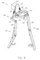
- FIG. 3shows another embodiment of the invention where exoskeleton trunk 109 further comprises a hip resilient element 116 configured to apply a torque between hip links 114 and 115 .
- a hip resilient elementinclude, without limitation, extension spring, compression spring, leaf spring, gas spring, air spring, rubber, elastomer, surgical tube, bungee cord and combinations thereof.
- the stiffness of hip resilient element 116may be chosen such that its force generally holds up the weight of the leg supports 101 or 102 during swing phase.
- Some embodimentsmay also include a hip abduction stop 211 which limits or prevents hip links 114 and 115 from abducting with respect to each other.
- abduction stop 211is created using a wire rope. Wire rope 211 prevents abduction of leg supports 101 and 102 from occurring but allows adduction of leg supports 101 and 102 .
- FIG. 4is a perspective drawing where exoskeleton trunk 109 includes two hip links 114 and 115 rotatably connectable to thigh links 103 and 104 allowing for flexion and extension of support legs 101 and 102 relative to exoskeleton trunk 109 , wherein hip links 114 and 115 are compliantly connected to each other allowing for abduction and/or adduction of leg supports 101 and 102 . In the example shown in FIG. 4 , this is accomplished by leaf spring 153 .
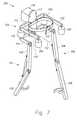
- FIG. 5is a perspective drawing wherein exoskeleton trunk 109 further comprises a connecting bracket 117 configured to transfer the weight of rear load 118 to exoskeleton trunk 109 .
- Exoskeleton trunk 109further comprises two hip links 114 and 115 rotatably connectable to thigh links 103 and 104 allowing for flexion and extension of leg supports 101 and 102 relative to exoskeleton trunk 109 .
- Hip links 114 and 115are rotatably connected to connecting bracket 117 via two hip abduction-adduction joints 176 and 177 and rotate about two hip abduction-adduction axes 178 and 179 .
- hip abduction-adduction axes 178 and 179are generally parallel to each other. In some embodiments, hip abduction-adduction joints 176 and 177 coincide with each other. Furthermore, in some embodiments, as shown in FIG. 6 , hip abduction-adduction joints 176 and 177 coincide with each other forming hip abduction-adduction joint 113 and hip abduction-adduction axes 178 and 179 become one hip abduction-adduction axis 112 .
- exoskeleton trunk 109further comprises hip abduction-adduction resilient elements 121 and 122 configured to apply torques between hip links 114 and 115 and connecting bracket 117 .
- hip abduction-adduction resilient elementsinclude, without limitation, extension spring, compression spring, gas spring, air spring, rubber, surgical tube, leaf springs, bungee cord and combinations thereof.
- the stiffness of hip abduction-adduction resilient elements 121 and 122may be chosen such that its force generally holds up the weight of the leg supports 101 or 102 during swing phase and aid the person in keeping the load oriented vertically while walking.
- connecting bracket 117further comprises extension frames 119 and 120 configured to hold front load 154 in front of person 187 .
- exoskeleton trunk 109comprises human interface device 150 capable of coupling person 187 to lower extremity exoskeleton 100 .
- human interface device 150comprise an element or combination of elements including, without limitation, vests, belts, straps, shoulder straps, chest straps, body cast, harness, and waist belts.
- human interface device 150transfers a portion of the weight of person 187 to exoskeleton trunk 109 .
- FIG. 13shows an embodiment where human interface device 150 comprises a specially-designed harness 229 to fit the body of person 187 . Harness 229 transfers a portion of the weight of person 187 to exoskeleton trunk 109 .
- hip links 114 and 115are compliantly connected to connecting bracket 117 . In the embodiment shown in FIG. 8 , this is accomplished by a hip resilient member 153 which in this case is a leaf spring.
- exoskeleton trunk 109comprises a backpack frame 180 that allows a backpack to be coupled to lower extremity exoskeleton 100 .
- backpack frame 180is connected to connecting bracket 117 .
- the human interface devices 150(such as a belt and shoulder straps) have been omitted in this figure for clarity.
- FIG. 9is a perspective drawing wherein leg supports 101 and 102 further include thigh abduction-adduction joints 123 and 124 configured to allow abduction and/or adduction of leg supports 101 and 102 about axes 202 and 203 respectively.
- thigh abduction-adduction joints 123 and 124are located below hip flexion-extension joints 125 and 126 . These joints are shown in greater detail in FIG. 10 which is a partial view of the same embodiment of FIG. 9 .
- leg supports 101 and 102comprise a thigh adduction stop 185 which limits or prevents thigh links 103 and 104 from adducting at joint 123 and 124 .
- Abduction and adduction of leg support 101are shown by arrows 227 and 228 respectively.
- thigh abduction-adduction joint 123includes a thigh adduction stop 185 which bears on a thigh stop surface 186 .
- Thigh adduction stop 185limits the adduction of thigh abduction-adduction joint 123 .
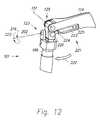
- leg supports 101 and 102further include thigh rotation joints 127 and 128 configured to allow rotation of leg supports 101 and 102 .
- Rotation joints 127 and 128are generally located above knee joints 107 and 108 .
- Lines 164 and 165represent the rotation axes of rotation joints 127 and 128 . In FIGS. 10 and 11 , this is accomplished by providing for a sliding contact between the hip rotation shaft 166 and the hip rotation journal 168 .
- the parts included in the joint which prevent it from pulling aparthave been omitted for simplicity, but one skilled in the art will note that there are many ways of retaining such shafts in such journals.
- rotation joints 127 and 128further comprise a rotation resilient element 129 .
- This rotation resilient elementacts as a torsion spring and provides a restoring torque which generally restores the leg support back to the neutral position shown in FIG. 9 .
- Rotation resilient element 129can be constructed in many ways with the particular cross section shown in FIG. 11 being advantageous when using an elastomeric material to construct the element. Rotation resilient element 129 is shown partially deflected for illustration purposes.
- leg supports 101 and 102further comprise compression-elongation mechanisms 131 and 132 configured to change the distance between exoskeleton trunk 109 and the respective knee flexion-extension joints 107 and 108 .
- compression-elongation mechanisms 131 and 132allow for changes in the distance between the hip flexion-extension joints 125 and 126 and the respective knee flexion-extension joints 107 and 108 .
- the compression-elongation mechanismscontracts by hip rotation shaft 166 sliding further into the hip rotation journal 168 (shown for leg 101 only).
- the leg rotation resilient element 129is allowed to slide into a clearance cavity 170 .
- compression-elongation mechanism 131 and 132further comprise a leg compression-elongation resilient element 133 .
- This leg compression-elongation resilient elementacts as a spring and provides a restoring force which generally restores the leg support back to a neutral configuration. In the embodiment of FIG. 11 , this is illustrated by a helical compression spring.
- lower extremity exoskeleton 100further comprises two swing resilient elements configured to apply torque between thigh links 103 and 104 and exoskeleton trunk 109 .
- swing resilient element 221pushes leg support 101 forward along arrows 222 during swing phase. This allows the person to swing the thigh links forward with less effort.
- swing resilient element 221is a gas spring.
- Gas spring 221includes a gas spring piston 223 and a gas spring cylinder 224 . In operation the force of compressed gas 225 in gas spring cylinder 224 forces gas spring piston 223 against cam 226 thereby pushing leg support 101 along arrow 222 .
- swing resilient element 221examples include, without limitation, extension spring, compression spring, leaf spring, gas spring, air spring, rubber, elastomer, surgical tube, bungee cord and combinations thereof.
- extension springcompression spring
- leaf springleaf spring
- gas springair spring
- rubberelastomer
- surgical tubebungee cord
- combinations thereofThe stiffness of swing resilient element 221 may be chosen to give appropriate level of comfort.
- exoskeleton trunk cover 171may cover some components of exoskeleton trunk 109 including parts of hip links 114 and 115 .
- the operation of the exoskeleton trunkis the same as in FIG. 3 or 6 depending on the preferred choice of hip resilient element 116 or hip abduction-adduction resilient elements 121 and 122 .
- thigh links 103 and 104comprise thigh holding devices 135 and 136 configured to allow person 187 to couple to leg supports 101 and 102 .
- Each thigh holding device 135 or 136comprises an element or combination of elements including, without limitation, straps, bars, c-shape brackets, body cast, and elastomers.
- shank links 105 and 106include comprise holding devices 137 and 138 configured to allow person 187 to couple to leg supports 101 and 102 .
- Each shank holding device 137 and 138comprises an element or combination of elements including, without limitation, straps, bars, c-shape brackets, body cast, and elastomers.
- leg supports 101 and 102further comprise exoskeleton feet 139 and 140 coupled to shank links 105 and 106 respectively, allowing the transfer of forces from shank links 105 and 106 to the ground.
- exoskeleton feet 139 and 140are configurable to be coupled to the feet of person 187 .
- the coupling to person's feetis accomplished by using clam-shell type bindings 205 and 206 sometimes found on modem snow shoes.
- clam-shell type bindings 205 and 206sometimes found on modem snow shoes.
- there are a great number of methods to make such a connectionas can be seen on different types of snow skis, snowboards, snowshoes and other such devices.
- FIG. 9shows that can be seen on different types of snow skis, snowboards, snowshoes and other such devices.
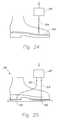
- exoskeleton feet 139 and 140comprise exoskeleton shoes 188 and 189 wearable by person 187 thereby allowing exoskeleton feet 139 and 140 to couple to the feet of person 187 .
- exoskeleton feet 139 and 140comprise exoskeleton insoles 157 and 158 insertable inside the person's shoes, allowing exoskeleton feet 139 and 140 to couple to the feet of person 187 .
- Insoles 157 and 158are flexible and therefore can bend to match the curvature of the human foot during maneuvers such as squatting.
- the insole side supports 212are either compliant or configured to include degrees of freedom to mimic the movement of the human ankle.
- exoskeleton feet 139 and 140are compliantly coupled to shank links 105 and 106 . This is accomplished using ankle resilient elements 181 and 182 .
- FIG. 16shows a close-up view of exoskeleton feet 139 .
- ankle resilient elements 181 (and 182 )each are constructed of a metal ball-and-socket joint 231 surrounded by an elastomer donut shape element 230 which creates compliance in all directions of rotations.
- exoskeleton feet 139 and 140rotate about two plantar-dorsi flexion axes relative to shank links 105 and 106 .
- FIG. 17shows an embodiment of this type of exoskeleton where ankle plantar-dorsi flexion axis 172 is generally parallel to the plantar-dorsi flexion axis in the human ankle.
- each leg supportfurther comprises at least one ankle plantar-dorsi flexion resilient element 141 resisting the rotation of respective exoskeleton foot about ankle plantar-dorsi flexion axis 172 .
- exoskeleton feet 139 and 140rotate about two ankle abduction-adduction axes 174 relative to shank links 105 and 106 .
- FIG. 18shows an embodiment of this type of exoskeleton where ankle abduction-adduction axis 174 is generally parallel to the abduction-adduction axis in the human ankle.
- each leg supportfurther comprises at least one ankle abduction-adduction resilient element 142 resisting the rotation of exoskeleton foot 139 about ankle abduction-adduction axis 174 .
- exoskeleton feet 139 and 140rotate about two ankle rotation axes 147 and 148 relative to shank links 105 and 106 . In some cases, this is accomplished using a shank rotation joint 207 which functions similar to leg rotation joint 127 .
- FIG. 19shows an embodiment of this type of exoskeleton where ankle rotation axis 147 is generally parallel to the rotation axis in the human ankle.
- resilient elementscan be included in the ankle to resist the rotation of the exoskeleton foot 139 about ankle rotation axis 147 .
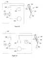
- foot sensors 160are integrated into exoskeleton feet 139 and 140 .
- foot sensor 160is a pressure sensor measuring the pressure in a media 191 trapped in a foot sensor cavity 192 inside exoskeleton foot 139 .
- FIG. 16shows an embodiment where a tube is used as a foot sensor cavity 192 .
- Pressure sensor 160measures the pressure in a media 191 trapped in a foot sensor cavity 192 .
- the stance signal 219may take the form of the media 191 itself ported in a small tube from the cavity 192 to signal processor 159 .
- FIG. 23shows another embodiment wherein foot sensor 160 is a force sensor connectable to exoskeleton foot 139 .
- foot sensor 160is located inside the human shoe like an insole and its output signal represents the force on the bottom of the human foot. This type would be particularly useful in embodiments of the invention such as those shown in FIG. 14 or 15 .
- foot sensor 160is connected to the bottom of the human shoe and senses the force on the bottom of the human foot.
- foot sensor 160is located inside the human shoe sole and senses the force on the bottom of the human foot.
- Foot sensor 160comprises any sensor or combination of sensors capable of performing the indicated functions. Examples of foot sensor 160 include, without limitation, force sensors, strain-gage based force sensors, piezoelectric force sensors, force sensing resistors, pressure sensors, switches, tape switches and combinations thereof. In some embodiments foot sensor 160 is a switch that represents the existence of a force greater than some threshold force on the bottom of the foot of person 187 .
- lower extremity exoskeleton 100further includes two compliant elements connecting thigh links 103 and 104 to exoskeleton trunk 109 assisting the operator in swinging the leg forward. This allows the operator to swing the thigh links forwardly with less effort.
- FIG. 27shows an embodiment of the invention where tensile spring 233 connects thigh link 103 to hip link 114 via extension frame 119 . Similarly tensile spring 234 connects thigh link 104 to hip link 115 via extension frame 120 .
- FIG. 21Also shown in FIG. 21 is an additional thigh abduction-adduction joint 235 which is included in order to allow the leg to be stowed in a vertical position when the exoskeleton is not in use but needs to be carried.
- Leg support 101can abduct along axis 237 . This may be desirable if the operator no longer has a very heavy load to carry but needs to transport lower extremity exoskeleton 100 . In that case, the operator may unstrap the exoskeleton's right leg support 101 and swing the leg outward from his or her body until the right exoskeleton foot 139 is in the air over the operator's head.
- the legcan be positioned such that it stows behind the operator as shown in FIG. 36 .
- the right thigh abduction-adduction joint 123 and the additional right thigh abduction-adduction joint 235each allow for a rotation of approximately ninety degrees about the right thigh abduction-adduction axis 202 and the additional right thigh abduction-adduction axis 237 respectively.
- the total abduction possibletherefore is over 180 degrees.
Landscapes
- Health & Medical Sciences (AREA)
- Life Sciences & Earth Sciences (AREA)
- Public Health (AREA)
- Veterinary Medicine (AREA)
- Epidemiology (AREA)
- Pain & Pain Management (AREA)
- Physical Education & Sports Medicine (AREA)
- General Health & Medical Sciences (AREA)
- Animal Behavior & Ethology (AREA)
- Rehabilitation Therapy (AREA)
- Engineering & Computer Science (AREA)
- Mechanical Engineering (AREA)
- Robotics (AREA)
- Prostheses (AREA)
- Rehabilitation Tools (AREA)
- Manipulator (AREA)
Abstract
Description
Claims (79)
Priority Applications (1)
| Application Number | Priority Date | Filing Date | Title |
|---|---|---|---|
| US11/404,719US8057410B2 (en) | 2005-04-13 | 2006-04-13 | Semi-powered lower extremity exoskeleton |
Applications Claiming Priority (2)
| Application Number | Priority Date | Filing Date | Title |
|---|---|---|---|
| US67134805P | 2005-04-13 | 2005-04-13 | |
| US11/404,719US8057410B2 (en) | 2005-04-13 | 2006-04-13 | Semi-powered lower extremity exoskeleton |
Publications (2)
| Publication Number | Publication Date |
|---|---|
| US20070056592A1 US20070056592A1 (en) | 2007-03-15 |
| US8057410B2true US8057410B2 (en) | 2011-11-15 |
Family
ID=37115767
Family Applications (1)
| Application Number | Title | Priority Date | Filing Date |
|---|---|---|---|
| US11/404,719Active2029-09-27US8057410B2 (en) | 2005-04-13 | 2006-04-13 | Semi-powered lower extremity exoskeleton |
Country Status (9)
| Country | Link |
|---|---|
| US (1) | US8057410B2 (en) |
| EP (1) | EP1874239B1 (en) |
| CN (1) | CN101175456B (en) |
| AU (1) | AU2006236579B2 (en) |
| CA (1) | CA2604892C (en) |
| ES (1) | ES2491218T3 (en) |
| IL (1) | IL186181A (en) |
| PL (1) | PL1874239T3 (en) |
| WO (1) | WO2006113520A2 (en) |
Cited By (70)
| Publication number | Priority date | Publication date | Assignee | Title |
|---|---|---|---|---|
| US20080249438A1 (en)* | 2007-04-06 | 2008-10-09 | University Of Delaware | Passive Swing Assist Leg Exoskeleton |
| US20090112134A1 (en)* | 2005-01-24 | 2009-04-30 | Kineticure Limited | Devices and method for applying vibrations to joints |
| US20100217163A1 (en)* | 2007-09-27 | 2010-08-26 | University Of Tsukuba | Rotation adjustment apparatus and method of controlling rotary apparatus |
| US20130145530A1 (en)* | 2011-12-09 | 2013-06-13 | Manu Mitra | Iron man suit |
| US20130231595A1 (en)* | 2010-09-17 | 2013-09-05 | The Regents Of The University Of California | Human Machine Interface for Human Exoskeleton |
| US20130245512A1 (en)* | 2008-10-13 | 2013-09-19 | Argo Medical Technologies Ltd. | Locomotion assisting device and method |
| US20130310949A1 (en)* | 2012-05-15 | 2013-11-21 | Vanderbilt University | Stair ascent and descent control for powered lower limb devices |
| US20140277739A1 (en)* | 2013-03-15 | 2014-09-18 | Sri International | Exosuit System |
| US20140276262A1 (en)* | 2013-03-14 | 2014-09-18 | Elwha Llc | Leg locomotion devices |
| US20140303539A1 (en)* | 2013-04-08 | 2014-10-09 | Elwha Llc | Apparatus, System, and Method for Controlling Movement of an Orthopedic Joint Prosthesis in a Mammalian Subject |
| US20150173929A1 (en)* | 2012-09-07 | 2015-06-25 | The Regents Of The University Of California | Controllable passive artificial knee |
| US20150217444A1 (en)* | 2014-01-13 | 2015-08-06 | Massachusetts Institute Of Technology | Wearable Robot Assisting Manual Tasks |
| US20150342820A1 (en)* | 2014-05-27 | 2015-12-03 | Toyota Jidosha Kabushiki Kaisha | Walk training apparatus and walk training method thereof |
| US9259343B2 (en) | 2012-07-06 | 2016-02-16 | Newman Technologies LLC | Device for mitigating plantar fasciitis |
| US9333644B2 (en) | 2010-04-09 | 2016-05-10 | Lockheed Martin Corporation | Portable load lifting system |
| JP2016096993A (en)* | 2014-11-20 | 2016-05-30 | テイ・エス テック株式会社 | Chair device |
| US9351900B2 (en) | 2012-09-17 | 2016-05-31 | President And Fellows Of Harvard College | Soft exosuit for assistance with human motion |
| US9351855B2 (en) | 2008-06-16 | 2016-05-31 | Ekso Bionics, Inc. | Powered lower extremity orthotic and method of operation |
| US9370439B2 (en) | 2010-04-07 | 2016-06-21 | Stéphane Bédard | Load distribution device for human joints |
| US9439797B2 (en) | 2013-04-08 | 2016-09-13 | Elwha Llc | Apparatus, system, and method for controlling movement of an orthopedic joint prosthesis in a mammalian subject |
| US20160262969A1 (en)* | 2015-03-10 | 2016-09-15 | Jtekt Corporation | Swinging joint device, walking assisting device, conveying device, manipulator, and walking-ability assisting device |
| WO2016187275A1 (en) | 2015-05-18 | 2016-11-24 | The Regents Of The University Of California | Method and apparatus for human arm supporting exoskeleton |
| US9504623B2 (en) | 2010-04-09 | 2016-11-29 | Ekso Bionics, Inc. | Exoskeleton load handling system and method of use |
| US20170086931A1 (en)* | 2015-09-25 | 2017-03-30 | Ethicon Endo-Surgery, Llc | Hybrid robotic surgery with mirrored and mimicked motion |
| US9610208B2 (en) | 2008-05-20 | 2017-04-04 | Ekso Bionics, Inc. | Device and method for decreasing energy consumption of a person by use of a lower extremity exoskeleton |
| USD789254S1 (en)* | 2014-05-23 | 2017-06-13 | Honda Motor Co., Ltd. | Upper body support frame with electric motor for walking aids |
| US9750978B2 (en) | 2014-08-25 | 2017-09-05 | Toyota Jidosha Kabushiki Kaisha | Gait training apparatus and control method therefor |
| US9801772B2 (en) | 2010-10-06 | 2017-10-31 | Ekso Bionics, Inc. | Human machine interfaces for lower extremity orthotics |
| US9808073B1 (en) | 2014-06-19 | 2017-11-07 | Lockheed Martin Corporation | Exoskeleton system providing for a load transfer when a user is standing and kneeling |
| US20180092795A1 (en)* | 2016-10-01 | 2018-04-05 | Norval Nicholas Fagan | Manual Walk-Assist and Accessories Combo |
| US20180200136A1 (en)* | 2017-01-19 | 2018-07-19 | Toyota Jidosha Kabushiki Kaisha | Walking assistant harness |
| US10124484B1 (en) | 2015-12-08 | 2018-11-13 | Lockheed Martin Corporation | Load-bearing powered exoskeleton using electromyographic control |
| US10130432B2 (en) | 2015-09-25 | 2018-11-20 | Ethicon Llc | Hybrid robotic surgery with locking mode |
| US10194906B2 (en) | 2015-09-25 | 2019-02-05 | Ethicon Llc | Hybrid robotic surgery with manual and robotic modes |
| US10195736B2 (en) | 2015-07-17 | 2019-02-05 | Lockheed Martin Corporation | Variable force exoskeleton hip joint |
| US20190083351A1 (en)* | 2017-09-21 | 2019-03-21 | Toyota Jidosha Kabushiki Kaisha | Load-relieving apparatus |
| US10258419B2 (en) | 2015-09-25 | 2019-04-16 | Ethicon Llc | Methods for hybrid robotic laparoscopic surgery |
| US10278883B2 (en)* | 2014-02-05 | 2019-05-07 | President And Fellows Of Harvard College | Systems, methods, and devices for assisting walking for developmentally-delayed toddlers |
| US20190151183A1 (en)* | 2017-11-20 | 2019-05-23 | The Regents Of The University Of California | Exoskeleton support mechanism for a medical exoskeleton |
| US20190209415A1 (en)* | 2016-12-28 | 2019-07-11 | Samsung Electronics Co., Ltd. | Sensor device and walking assist device using the sensor device |
| US20190216669A1 (en)* | 2018-01-18 | 2019-07-18 | Toyota Jidosha Kabushiki Kaisha | Walking training apparatus and control method thereof |
| US10390973B2 (en) | 2015-05-11 | 2019-08-27 | The Hong Kong Polytechnic University | Interactive exoskeleton robotic knee system |
| US20190274437A1 (en)* | 2011-04-27 | 2019-09-12 | Robert L. Distler | Portable deployable stanchion to assist an individual at rest |
| US10434030B2 (en) | 2014-09-19 | 2019-10-08 | President And Fellows Of Harvard College | Soft exosuit for assistance with human motion |
| US10442078B2 (en) | 2014-06-18 | 2019-10-15 | Mawashi Protective Clothing Inc | Exoskeleton and method of using the same |
| US10485616B2 (en) | 2015-09-25 | 2019-11-26 | Ethicon Llc | Hybrid robotic surgery with power assisted motion |
| US10518404B2 (en) | 2015-07-17 | 2019-12-31 | Lockheed Martin Corporation | Variable force exoskeleton hip joint |
| US10548800B1 (en) | 2015-06-18 | 2020-02-04 | Lockheed Martin Corporation | Exoskeleton pelvic link having hip joint and inguinal joint |
| US10828527B2 (en)* | 2017-11-07 | 2020-11-10 | Seismic Holdings, Inc. | Exosuit system systems and methods for assisting, resisting and aligning core biomechanical functions |
| US10843332B2 (en) | 2013-05-31 | 2020-11-24 | President And Fellow Of Harvard College | Soft exosuit for assistance with human motion |
| US10864100B2 (en) | 2014-04-10 | 2020-12-15 | President And Fellows Of Harvard College | Orthopedic device including protruding members |
| US20210000677A1 (en)* | 2019-07-01 | 2021-01-07 | Toyota Jidosha Kabushiki Kaisha | State estimation program, trained model, rehabilitation support system, learning apparatus, and state estimation method |
| US10912346B1 (en) | 2015-11-24 | 2021-02-09 | Lockheed Martin Corporation | Exoskeleton boot and lower link |
| US11014804B2 (en) | 2017-03-14 | 2021-05-25 | President And Fellows Of Harvard College | Systems and methods for fabricating 3D soft microstructures |
| US20210205651A1 (en)* | 2017-01-26 | 2021-07-08 | The Regents Of The University Of Michigan | Resistive Device Employing Eddy Current Braking |
| US11141341B2 (en)* | 2018-05-05 | 2021-10-12 | Eleni KOLTZI | System and method for stroke rehabilitation using position feedback based exoskeleton control introduction |
| US11166866B2 (en)* | 2017-06-20 | 2021-11-09 | Shenzhen Hanix United, Ltd. | Lower limb training rehabilitation apparatus |
| US11202934B2 (en)* | 2018-02-05 | 2021-12-21 | Hyeong Sic KIM | Upper and lower limb walking rehabilitation device |
| US11207014B2 (en) | 2017-08-30 | 2021-12-28 | Lockheed Martin Corporation | Automatic sensor selection |
| US11324655B2 (en) | 2013-12-09 | 2022-05-10 | Trustees Of Boston University | Assistive flexible suits, flexible suit systems, and methods for making and control thereof to assist human mobility |
| US11324653B2 (en) | 2014-11-27 | 2022-05-10 | Marsi Bionics S.L. | Exoskeleton for assisting human movement |
| US11331538B2 (en)* | 2018-08-07 | 2022-05-17 | Interactive Strength, Inc. | Interactive exercise machine data architecture |
| US11458061B1 (en)* | 2019-03-21 | 2022-10-04 | Empower Robotics Corporation | Control of multiple joints of an upper body support system |
| US20220323826A1 (en)* | 2021-04-11 | 2022-10-13 | Vikas Khurana | System, apparatus and method for training a subject |
| US11491071B2 (en)* | 2017-12-21 | 2022-11-08 | Southeast University | Virtual scene interactive rehabilitation training robot based on lower limb connecting rod model and force sense information and control method thereof |
| US11498203B2 (en) | 2016-07-22 | 2022-11-15 | President And Fellows Of Harvard College | Controls optimization for wearable systems |
| US20220409418A1 (en)* | 2021-06-25 | 2022-12-29 | Donggwan PARK | Human body flexion and extension assist device |
| US11590046B2 (en) | 2016-03-13 | 2023-02-28 | President And Fellows Of Harvard College | Flexible members for anchoring to the body |
| USD997108S1 (en) | 2021-08-13 | 2023-08-29 | Festool Gmbh | Operating element for a robotic exoskeleton |
| US12440366B2 (en)* | 2021-06-25 | 2025-10-14 | Donggwan PARK | Human body flexion and extension assist device |
Families Citing this family (119)
| Publication number | Priority date | Publication date | Assignee | Title |
|---|---|---|---|---|
| US6966882B2 (en)* | 2002-11-25 | 2005-11-22 | Tibion Corporation | Active muscle assistance device and method |
| US7628766B1 (en)* | 2003-10-29 | 2009-12-08 | The Regents Of The University Of California | Lower extremity enhancer |
| US7645246B2 (en)* | 2004-08-11 | 2010-01-12 | Omnitek Partners Llc | Method for generating power across a joint of the body during a locomotion cycle |
| EP1946429B1 (en) | 2005-08-10 | 2017-06-21 | Bionic Power Inc. | Methods and apparatus for harvesting biomechanical energy |
| AU2007223733B2 (en)* | 2006-03-09 | 2013-01-10 | The Regents Of The University Of California | Power generating leg |
| DE102006021802A1 (en) | 2006-05-09 | 2007-11-15 | Otto Bock Healthcare Ip Gmbh & Co. Kg | Control of a passive prosthetic knee joint with adjustable damping |
| WO2008129096A1 (en)* | 2007-04-23 | 2008-10-30 | Golden Crab, S.L. | Exoskeleton for safety and control while skiing |
| EP2153804A1 (en)* | 2007-04-23 | 2010-02-17 | Golden Crab, S.L. | Exoskeleton |
| RU2362598C2 (en)* | 2007-09-10 | 2009-07-27 | Общество с ограниченной ответственностью "Транспортные шагающие системы" | Passive cargo exoskeleton, knee hinge for passive cargo exoskeleton, compensator for passive cargo exoskeleton |
| DE102007053389A1 (en) | 2007-11-07 | 2009-05-20 | Otto Bock Healthcare Ip Gmbh & Co. | Method for controlling an orthopedic joint |
| CA2710677C (en)* | 2007-12-26 | 2016-10-18 | Richard Little | Mobility aid |
| WO2010019300A1 (en)* | 2008-05-20 | 2010-02-18 | University Of California At Berkeley | Device and method for decreasing oxygen consumption of a person during steady walking by use of a load-carrying exoskeleton |
| DE102008024748A1 (en)* | 2008-05-20 | 2009-12-03 | Otto Bock Healthcare Gmbh | Knee orthosis and method for controlling a knee brace |
| AU2009269892B2 (en)* | 2008-06-16 | 2014-05-08 | Ekso Bionics, Inc. | Semi-actuated transfemoral prosthetic knee |
| AU2009273927B2 (en)* | 2008-07-23 | 2014-09-18 | Ekso Bionics, Inc. | An exoskeleton and method of reducing the energy consumption of a person in motion coupled to an exoskeleton device |
| WO2010036791A1 (en)* | 2008-09-24 | 2010-04-01 | Berkeley Bionics | Hip and knee actuation systems for lower limb orthotic devices |
| JP5165535B2 (en)* | 2008-11-05 | 2013-03-21 | 本田技研工業株式会社 | Walking assist device |
| JP5235838B2 (en)* | 2008-11-06 | 2013-07-10 | 本田技研工業株式会社 | Walking assist device |
| US20100113986A1 (en)* | 2008-11-06 | 2010-05-06 | Honda Motor Co., Ltd. | Walking assist apparatus |
| JP5073642B2 (en)* | 2008-12-17 | 2012-11-14 | 本田技研工業株式会社 | Operation assistance device |
| AU2009341585B2 (en)* | 2008-12-18 | 2015-06-18 | Ekso Bionics, Inc. | Wearable material handling system |
| IT1393776B1 (en)* | 2009-04-03 | 2012-05-08 | Fond Istituto Italiano Di Tecnologia | ELASTIC ROTARY ACTUATOR, PARTICULARLY FOR ROBOTIC APPLICATIONS, AND METHOD FOR ITS CONTROL |
| KR101709605B1 (en) | 2009-07-01 | 2017-02-23 | 렉스 바이오닉스 리미티드 | Control system for a mobility aid |
| US20130158445A1 (en)* | 2010-08-23 | 2013-06-20 | The Regents Of The University Of California | Orthesis system and methods for control of exoskeletons |
| US9480618B2 (en)* | 2010-10-05 | 2016-11-01 | Elizabeth T. Hsiao-Wecksler | Portable active pneumatically powered ankle-foot orthosis |
| JP5841787B2 (en)* | 2011-02-25 | 2016-01-13 | 川崎重工業株式会社 | Wearable motion support device |
| WO2012081107A1 (en) | 2010-12-16 | 2012-06-21 | トヨタ自動車株式会社 | Walking assist apparatus |
| US8474672B1 (en)* | 2011-03-29 | 2013-07-02 | Michael R. Keith | Hiker's buddy apparatus for sharing with a hiker the carrying load of a backpack |
| US9719633B2 (en)* | 2011-05-06 | 2017-08-01 | Garrett W. Brown | Exoskeleton arm interface |
| US8736087B2 (en) | 2011-09-01 | 2014-05-27 | Bionic Power Inc. | Methods and apparatus for control of biomechanical energy harvesting |
| FR2981266B1 (en)* | 2011-10-17 | 2013-10-18 | Commissariat Energie Atomique | EXOSQUELETTE LOWER |
| US9095981B2 (en) | 2012-01-11 | 2015-08-04 | Garrett W. Brown | Load and torque resistant caliper exoskeleton |
| ITTO20120226A1 (en) | 2012-03-15 | 2012-06-14 | Torino Politecnico | ACTIVE TUTOR FOR MOTOR NEURORIABILATION OF LOWER LIMBS, SYSTEM INCLUDING THE SUITOR AND PROCEDURE FOR THE FUNCTIONING OF SUCH SYSTEM. |
| ITFI20120129A1 (en)* | 2012-06-21 | 2013-12-22 | Scuola Superiore Di Studi Universit Ari E Di Perfe | TECHNOLOGICAL ASSISTANCE FOR TRANSFEMORAL AMOUNTS |
| DE102012013141A1 (en)* | 2012-07-03 | 2014-05-08 | Otto Bock Healthcare Gmbh | Orthotic or prosthetic joint device and method for its control |
| WO2014081400A2 (en)* | 2012-11-21 | 2014-05-30 | Univerzitetni Rehabilitacijski Inštitut Republike Slovenije – Soča | Apparatus for training dynamic balance and turning manoeuvres during walking |
| CN103099691B (en)* | 2012-12-24 | 2014-12-17 | 东南大学 | Two-degree-of-freedom exoskeleton ankle joint mechanism |
| US8894595B2 (en)* | 2012-12-28 | 2014-11-25 | Stephen Hennessy | Traction hip brace |
| CN103006416B (en)* | 2013-01-04 | 2014-08-20 | 哈尔滨工程大学 | Mechanical lower-limb rehabilitation robot walker device |
| US9308642B2 (en)* | 2013-01-16 | 2016-04-12 | Arizona Board Of Regents On Behalf Of Arizona State University | Systems and methods for adding or subtracting energy to body motion |
| CN103142332B (en)* | 2013-02-25 | 2014-12-24 | 西南交通大学 | Assistance type two-stage coupling device used between back frame and hip part of exoskeleton |
| US9421143B2 (en)* | 2013-03-15 | 2016-08-23 | Bionik Laboratories, Inc. | Strap assembly for use in an exoskeleton apparatus |
| US9675514B2 (en) | 2013-03-15 | 2017-06-13 | Bionik Laboratories, Inc. | Transmission assembly for use in an exoskeleton apparatus |
| US9855181B2 (en) | 2013-03-15 | 2018-01-02 | Bionik Laboratories, Inc. | Transmission assembly for use in an exoskeleton apparatus |
| TWI511715B (en)* | 2013-03-27 | 2015-12-11 | Ind Tech Res Inst | Intention detection and gait adjustment device and method |
| KR101667179B1 (en)* | 2013-05-30 | 2016-10-17 | 호메이윤 카제루니 | User-coupled human-machine interface system and a control method of an exoskeleton thereof |
| US20140358053A1 (en)* | 2013-05-31 | 2014-12-04 | Case Western Reserve University | Power assisted orthosis with hip-knee synergy |
| CA2916674C (en) | 2013-07-09 | 2020-09-29 | John THRELFALL | External structural brace apparatus |
| US9226867B2 (en) | 2013-07-09 | 2016-01-05 | John Threlfall | External structural brace apparatus |
| US20150025423A1 (en) | 2013-07-19 | 2015-01-22 | Bionik Laboratories, Inc. | Control system for exoskeleton apparatus |
| KR20150039640A (en)* | 2013-10-02 | 2015-04-13 | 삼성전자주식회사 | Baby carrier |
| CN103519958B (en)* | 2013-10-10 | 2016-04-06 | 张静远 | A kind of Manual self-help stair climber |
| FR3016821B1 (en)* | 2014-01-29 | 2019-08-02 | Robotiques 3 Dimensions | EXOSQUELETTE WITH FRONT PORT AND METHOD OF USING SUCH AN EXOSQUELET. |
| TWI556809B (en) | 2014-03-27 | 2016-11-11 | 財團法人工業技術研究院 | Walking assist device |
| FR3020750B1 (en)* | 2014-05-06 | 2018-05-25 | Mobiiuz | BODY HOLDING DEVICE IN STANDING POSITION |
| US9604369B2 (en)* | 2014-06-04 | 2017-03-28 | Ekso Bionics, Inc. | Exoskeleton and method of increasing the flexibility of an exoskeleton hip joint |
| DE102014009028A1 (en)* | 2014-06-24 | 2015-12-24 | Otto Bock Healthcare Gmbh | Leg orthosis and orthosis |
| KR102250260B1 (en)* | 2014-07-17 | 2021-05-10 | 삼성전자주식회사 | A connecting module and a motion assist apparatus comprising thereof |
| KR102125078B1 (en) | 2014-08-07 | 2020-06-19 | 삼성전자주식회사 | A driving module, a motion assist apparatus comprising the driving module and a control method of the motion assist apparatus |
| US9757254B2 (en) | 2014-08-15 | 2017-09-12 | Honda Motor Co., Ltd. | Integral admittance shaping for an exoskeleton control design framework |
| KR102250238B1 (en)* | 2014-08-18 | 2021-05-10 | 삼성전자주식회사 | A fixing module and a motion assist apparatus comprising thereof |
| BR112015011000A2 (en)* | 2014-09-10 | 2017-07-11 | Uprobots S De R L De C V | adjustable mechanical exoskeleton for a bipedal animal with bone and muscle deficiency |
| US10449105B2 (en)* | 2014-10-26 | 2019-10-22 | Springactive, Inc. | System and method of bidirectional compliant joint torque actuation |
| US20160158593A1 (en)* | 2014-12-04 | 2016-06-09 | Florida Institute for Human and Machine Cognition | Exoskeleton-Based Exercise and Training Device |
| US20160213496A1 (en)* | 2015-01-28 | 2016-07-28 | Steering Solutions Ip Holding Corporation | Integrated power generation for human exoskeletons and method of generating power |
| KR102423702B1 (en)* | 2015-09-04 | 2022-07-21 | 삼성전자주식회사 | Motion assist apparatus and Method for controlling thereof |
| CN105147500B (en)* | 2015-10-16 | 2017-03-29 | 北京机械设备研究所 | A kind of ectoskeleton thigh attachment means |
| US10195099B2 (en)* | 2016-01-11 | 2019-02-05 | Bionic Power Inc. | Method and system for intermittently assisting body motion |
| EP3403775A4 (en)* | 2016-01-15 | 2020-01-22 | Kubota Corporation | AUXILIARY DEVICE |
| US20190125613A1 (en)* | 2016-04-15 | 2019-05-02 | Meconik Co., Ltd | Walking assistance device |
| KR101836636B1 (en) | 2016-05-19 | 2018-03-09 | 현대자동차주식회사 | Wearable walking assistant robot and method for controlling the same |
| WO2017213235A1 (en)* | 2016-06-08 | 2017-12-14 | 株式会社 東芝 | Motion assisting device |
| KR101878038B1 (en)* | 2016-06-15 | 2018-07-16 | 현대자동차주식회사 | Ankle-less walking assistant robot system and method for controlling the same |
| CN106041898B (en) | 2016-08-03 | 2018-05-22 | 京东方科技集团股份有限公司 | Mechanical exoskeleton wearable device and its progress control method and device |
| CN106239481A (en)* | 2016-08-31 | 2016-12-21 | 南京晨光集团有限责任公司 | A kind of exoskeleton robot micro hydraulic servosystem |
| IT201600099694A1 (en)* | 2016-10-05 | 2018-04-05 | Fondazione St Italiano Tecnologia | Exoskeleton for lower limbs |
| CN106351810B (en)* | 2016-10-14 | 2018-12-28 | 李艳芳 | Limb motion generating equipment |
| US10821614B2 (en) | 2016-11-11 | 2020-11-03 | Sarcos Corp. | Clutched joint modules having a quasi-passive elastic actuator for a robotic assembly |
| US10828767B2 (en) | 2016-11-11 | 2020-11-10 | Sarcos Corp. | Tunable actuator joint modules having energy recovering quasi-passive elastic actuators with internal valve arrangements |
| CN106726363B (en)* | 2017-03-13 | 2023-11-17 | 东北大学 | Wearable bionic hydraulic lower limb rehabilitation walking-assisting mechanical device |
| WO2018213427A1 (en)* | 2017-05-17 | 2018-11-22 | Lockheed Martin Corporation | Variable force exoskeleton hip joint |
| JP6945145B2 (en)* | 2017-06-26 | 2021-10-06 | パナソニックIpマネジメント株式会社 | Assist device and how to operate the assist device |
| RU2660312C1 (en)* | 2017-08-01 | 2018-07-05 | Федеральное государственное бюджетное учреждение "Центральный научно-исследовательский испытательный институт инженерных войск" Министерства обороны Российской Федерации | Method for determining efficiency of biomechanical anthropomorphic means (passive exoskeletons) |
| RU2660510C1 (en)* | 2017-08-01 | 2018-07-06 | Федеральное государственное бюджетное учреждение "Центральный научно-исследовательский испытательный институт инженерных войск" Министерства обороны Российской Федерации | Device for registration of parameters of redistributing mass of load of biomechanical anthropomorphic means (passive exoskeletons) |
| US10596012B2 (en) | 2017-10-27 | 2020-03-24 | Toyota Research Institute, Inc. | Artificial limb for host assistance |
| US10624809B2 (en)* | 2017-11-09 | 2020-04-21 | Free Bionics Taiwan Inc. | Exoskeleton robot and controlling method for exoskeleton robot |
| US10835443B2 (en)* | 2017-11-13 | 2020-11-17 | Free Bionics Taiwan Inc. | Exoskeleton robot |
| US10842243B2 (en)* | 2017-12-15 | 2020-11-24 | Pantelis Chatzidakis | Weight support systems |
| DE102018106846B3 (en)* | 2018-03-22 | 2019-07-04 | HAWE Altenstadt Holding GmbH | Human exoskeleton |
| CN108436890A (en)* | 2018-06-01 | 2018-08-24 | 刘伟 | A kind of pressure alternating simple ectoskeleton of conduction-type |
| WO2020051651A1 (en)* | 2018-09-10 | 2020-03-19 | Yavor Gegov | Exoskeleton |
| KR102172494B1 (en)* | 2018-10-08 | 2020-10-30 | 박동관 | Assistance apparatus for bending and stretching for human body |
| CN109303669A (en)* | 2018-10-17 | 2019-02-05 | 苏州帝维达生物科技有限公司 | A kind of multiple degrees of freedom movable lower limb healing robot |
| CN109172281B (en)* | 2018-10-17 | 2024-03-19 | 苏州帝维达生物科技有限公司 | A seven-degree-of-freedom lower limb rehabilitation robot |
| US11241801B2 (en) | 2018-12-31 | 2022-02-08 | Sarcos Corp. | Robotic end effector with dorsally supported actuation mechanism |
| CN109568088B (en)* | 2019-01-15 | 2024-03-19 | 四川大学锦城学院 | Helping hand upstairs and downstairs supporting leg |
| CN109630481B (en)* | 2019-01-21 | 2020-01-07 | 北京航空航天大学 | A single degree of freedom active knee joint prosthesis based on a closed hydraulic drive circuit |
| JP7100003B2 (en)* | 2019-09-13 | 2022-07-12 | 本田技研工業株式会社 | Assist device |
| EP3795306A1 (en)* | 2019-09-23 | 2021-03-24 | Hilti Aktiengesellschaft | Device for providing an assisting force for upper extremities of a user and an exoskeleton |
| DE102019130390A1 (en)* | 2019-11-11 | 2021-05-12 | Ottobock Se & Co. Kgaa | Orthopedic device for supporting a user's lower back |
| DE102020119166A1 (en)* | 2020-07-21 | 2022-01-27 | Ottobock Se & Co. Kgaa | Orthopedic device for supporting a user's lower extremity |
| CN113018790A (en)* | 2020-12-07 | 2021-06-25 | 邱存珍 | Artificial intelligence recovered device of taking exercise of orthopedics |
| US11833676B2 (en) | 2020-12-07 | 2023-12-05 | Sarcos Corp. | Combining sensor output data to prevent unsafe operation of an exoskeleton |
| CN117015363A (en)* | 2020-12-18 | 2023-11-07 | 贝泰米亚公司 | Load distribution device for improving the mobility of the centre of gravity of a user during complex movements |
| CN112891144B (en)* | 2021-01-28 | 2022-11-08 | 北京理工大学 | A positive-negative pressure hybrid drive flexible knee exoskeleton |
| US11918475B2 (en) | 2021-03-31 | 2024-03-05 | DePuy Synthes Products, Inc. | Modular acetabular surgical implant assembly |
| TWI783452B (en)* | 2021-04-20 | 2022-11-11 | 得圓開發股份有限公司 | Wearable support for loading exoskeleton |
| US20230101090A1 (en)* | 2021-09-27 | 2023-03-30 | Sarcos Corp. | System and Method for Restoring Robotic Assemblies to One Or More Self-Supporting Stable Support Positions |
| IT202100029327A1 (en)* | 2021-11-19 | 2023-05-19 | Robosuits Srl | SUPPORT FOOT FOR AN EXOSKELETON FOR CARRYING LOADS, EXOSKELETON INCLUDING SAID SUPPORT FOOT AND METHOD OF CONTROL OF AN EXOSKELETON |
| CN114131585B (en)* | 2021-12-22 | 2025-01-07 | 军事科学院系统工程研究院军需工程技术研究所 | Passive ground-contact knee exoskeleton robot and power assistance method thereof |
| CN114734427B (en)* | 2022-03-31 | 2023-09-01 | 北京大学 | A portable finger exoskeleton robot |
| CN115070732B (en)* | 2022-06-30 | 2025-01-17 | 中国农业科学院都市农业研究所 | Machine vision agricultural exoskeleton robot detector device and method |
| US11826907B1 (en) | 2022-08-17 | 2023-11-28 | Sarcos Corp. | Robotic joint system with length adapter |
| US11717956B1 (en) | 2022-08-29 | 2023-08-08 | Sarcos Corp. | Robotic joint system with integrated safety |
| WO2024098070A1 (en) | 2022-11-04 | 2024-05-10 | Sarcos Corp. | Robotic end-effector having dynamic stiffening elements with resilient spacers for conforming object interaction |
| US11897132B1 (en) | 2022-11-17 | 2024-02-13 | Sarcos Corp. | Systems and methods for redundant network communication in a robot |
| US11924023B1 (en) | 2022-11-17 | 2024-03-05 | Sarcos Corp. | Systems and methods for redundant network communication in a robot |
| CN115919615B (en)* | 2022-12-23 | 2025-06-27 | 北京工业大学 | Walking aid device and method for passive suspension type backpack exoskeleton |
| CN117921637B (en)* | 2024-03-19 | 2024-07-05 | 江西服装学院 | Passive exoskeleton device based on energy trans-articular transfer |
Citations (42)
| Publication number | Priority date | Publication date | Assignee | Title |
|---|---|---|---|---|
| US406328A (en) | 1889-07-02 | Peters | ||
| US420178A (en) | 1890-01-28 | running | ||
| US420179A (en) | 1890-01-28 | Apparatus for facilitating walking | ||
| US440684A (en) | 1890-11-18 | Apparatus for facilitating walking | ||
| US539872A (en) | 1895-05-28 | Exercising apparatus | ||
| US807908A (en) | 1904-06-30 | 1905-12-19 | Auto Physical Trainer Company | Exercising device. |
| US979243A (en) | 1910-03-29 | 1910-12-20 | William W Anderson | Apparatus for facilitating walking. |
| US1308675A (en) | 1919-05-06 | 1919-07-01 | Leslie C Kelley | Pedomotor. |
| US4647004A (en) | 1977-10-06 | 1987-03-03 | Bihlmaier John A | Pneumatic-hydraulic actuator system |
| US4872665A (en)* | 1985-10-30 | 1989-10-10 | Chareire Jean Louis | Mechanical leg-propulsion assistance device |
| US5020790A (en) | 1990-10-23 | 1991-06-04 | Board Of Supervisors Of Louisiana State University And Agricultural And Mechanical College | Powered gait orthosis |
| US5282460A (en)* | 1992-01-06 | 1994-02-01 | Joyce Ann Boldt | Three axis mechanical joint for a power assist device |
| US5476441A (en) | 1993-09-30 | 1995-12-19 | Massachusetts Institute Of Technology | Controlled-brake orthosis |
| US5658242A (en) | 1991-03-13 | 1997-08-19 | Polycane Australia Pty Ltd. | Walking aid |
| US5662693A (en) | 1995-06-05 | 1997-09-02 | The United States Of America As Represented By The Secretary Of The Air Force | Mobility assist for the paralyzed, amputeed and spastic person |
| US5961476A (en) | 1997-07-28 | 1999-10-05 | Technology Research Association Of Medical And Welfare Apparatus | Walk assisting apparatus |
| US6422329B1 (en) | 1999-11-12 | 2002-07-23 | Homayoon Kazerooni | Human assisted walking robot |
| EP1260201A1 (en) | 2001-05-24 | 2002-11-27 | Argo Medical Technologies Ltd. | Gait-locomotor apparatus |
| US6500210B1 (en) | 1992-09-08 | 2002-12-31 | Seattle Systems, Inc. | System and method for providing a sense of feel in a prosthetic or sensory impaired limb |
| US20030018283A1 (en)* | 2001-06-29 | 2003-01-23 | Behzad Dariush | Feedback estimation of joint forces and joint moments |
| US6676707B2 (en) | 2001-05-24 | 2004-01-13 | Tachung C. Yih | Prosthetic devices for upper and lower limbs |
| US20040106881A1 (en)* | 2002-11-21 | 2004-06-03 | Mcbean John M. | Powered orthotic device |
| US20040116839A1 (en) | 2002-12-13 | 2004-06-17 | New Mexico Technical Research Foundation | Gait training apparatus |
| US20040158175A1 (en)* | 2001-06-27 | 2004-08-12 | Yasushi Ikeuchi | Torque imparting system |
| US6807869B2 (en) | 2001-11-29 | 2004-10-26 | Koninklijke Philips Electronics N.V. | Shoe based force sensor and equipment for use with the same |
| US6821233B1 (en) | 1998-11-13 | 2004-11-23 | Hocoma Ag | Device and method for automating treadmill therapy |
| US20040249319A1 (en)* | 2002-09-23 | 2004-12-09 | Behzad Dariush | Gravity compensation control system and method using multiple feasibility parameters |
| CN1586434A (en) | 2004-08-10 | 2005-03-02 | 浙江大学 | Lower limb walking external skeleton capable of being worn |
| US20050102111A1 (en)* | 2002-09-23 | 2005-05-12 | Behzad Dariush | Gravity compensation method in a human assist system and a human assist system with gravity compensation control |
| US6966882B2 (en) | 2002-11-25 | 2005-11-22 | Tibion Corporation | Active muscle assistance device and method |
| US20060046907A1 (en) | 2004-08-11 | 2006-03-02 | Rastegar Jahangir S | Power generation devices and methods |
| US7048707B2 (en) | 2000-05-26 | 2006-05-23 | Orthomerica Products, Inc. | Modular adjustable prophylactic hip orthosis and adduction/abduction joint |
| US7111704B2 (en) | 2004-01-30 | 2006-09-26 | Johnson Welded Products, Inc. | Hydrostatic drive apparatus for a road vehicle |
| US20060249315A1 (en) | 2005-03-31 | 2006-11-09 | Massachusetts Institute Of Technology | Artificial human limbs and joints employing actuators, springs, and variable-damper elements |
| US20060260620A1 (en) | 2005-01-18 | 2006-11-23 | The Regents Of University Of California | Lower extremity exoskeleton |
| WO2007016781A1 (en) | 2005-08-10 | 2007-02-15 | Simon Fraser University | Methods and apparatus for harvesting biomechanical energy |
| US20070043449A1 (en) | 2005-03-31 | 2007-02-22 | Massachusetts Institute Of Technology | Artificial ankle-foot system with spring, variable-damping, and series-elastic actuator components |
| US20070123997A1 (en) | 2005-03-31 | 2007-05-31 | Massachusetts Institute Of Technology | Exoskeletons for running and walking |
| US20070162152A1 (en) | 2005-03-31 | 2007-07-12 | Massachusetts Institute Of Technology | Artificial joints using agonist-antagonist actuators |
| US7313463B2 (en) | 2005-03-31 | 2007-12-25 | Massachusetts Institute Of Technology | Biomimetic motion and balance controllers for use in prosthetics, orthotics and robotics |
| CN101094640A (en) | 2004-12-28 | 2007-12-26 | 本田技研工业株式会社 | Body weight support device and body weight support program |
| US7445606B2 (en)* | 2004-08-11 | 2008-11-04 | Omnitek Partners Llc | Methods and devices for selective exercising of muscles |
- 2006
- 2006-04-13PLPL06750299Tpatent/PL1874239T3/enunknown
- 2006-04-13WOPCT/US2006/014227patent/WO2006113520A2/enactiveApplication Filing
- 2006-04-13AUAU2006236579Apatent/AU2006236579B2/enactiveActive
- 2006-04-13CNCN2006800170311Apatent/CN101175456B/enactiveActive
- 2006-04-13USUS11/404,719patent/US8057410B2/enactiveActive
- 2006-04-13EPEP06750299.7Apatent/EP1874239B1/enactiveActive
- 2006-04-13CACA2604892Apatent/CA2604892C/enactiveActive
- 2006-04-13ESES06750299.7Tpatent/ES2491218T3/enactiveActive
- 2007
- 2007-09-23ILIL186181Apatent/IL186181A/enactiveIP Right Grant
Patent Citations (45)
| Publication number | Priority date | Publication date | Assignee | Title |
|---|---|---|---|---|
| US406328A (en) | 1889-07-02 | Peters | ||
| US420178A (en) | 1890-01-28 | running | ||
| US420179A (en) | 1890-01-28 | Apparatus for facilitating walking | ||
| US440684A (en) | 1890-11-18 | Apparatus for facilitating walking | ||
| US539872A (en) | 1895-05-28 | Exercising apparatus | ||
| US807908A (en) | 1904-06-30 | 1905-12-19 | Auto Physical Trainer Company | Exercising device. |
| US979243A (en) | 1910-03-29 | 1910-12-20 | William W Anderson | Apparatus for facilitating walking. |
| US1308675A (en) | 1919-05-06 | 1919-07-01 | Leslie C Kelley | Pedomotor. |
| US4647004A (en) | 1977-10-06 | 1987-03-03 | Bihlmaier John A | Pneumatic-hydraulic actuator system |
| US4872665A (en)* | 1985-10-30 | 1989-10-10 | Chareire Jean Louis | Mechanical leg-propulsion assistance device |
| US5020790A (en) | 1990-10-23 | 1991-06-04 | Board Of Supervisors Of Louisiana State University And Agricultural And Mechanical College | Powered gait orthosis |
| US5658242A (en) | 1991-03-13 | 1997-08-19 | Polycane Australia Pty Ltd. | Walking aid |
| US5282460A (en)* | 1992-01-06 | 1994-02-01 | Joyce Ann Boldt | Three axis mechanical joint for a power assist device |
| US6500210B1 (en) | 1992-09-08 | 2002-12-31 | Seattle Systems, Inc. | System and method for providing a sense of feel in a prosthetic or sensory impaired limb |
| US5476441A (en) | 1993-09-30 | 1995-12-19 | Massachusetts Institute Of Technology | Controlled-brake orthosis |
| US5662693A (en) | 1995-06-05 | 1997-09-02 | The United States Of America As Represented By The Secretary Of The Air Force | Mobility assist for the paralyzed, amputeed and spastic person |
| US5961476A (en) | 1997-07-28 | 1999-10-05 | Technology Research Association Of Medical And Welfare Apparatus | Walk assisting apparatus |
| US6821233B1 (en) | 1998-11-13 | 2004-11-23 | Hocoma Ag | Device and method for automating treadmill therapy |
| US6422329B1 (en) | 1999-11-12 | 2002-07-23 | Homayoon Kazerooni | Human assisted walking robot |
| US7048707B2 (en) | 2000-05-26 | 2006-05-23 | Orthomerica Products, Inc. | Modular adjustable prophylactic hip orthosis and adduction/abduction joint |
| US6676707B2 (en) | 2001-05-24 | 2004-01-13 | Tachung C. Yih | Prosthetic devices for upper and lower limbs |
| EP1260201A1 (en) | 2001-05-24 | 2002-11-27 | Argo Medical Technologies Ltd. | Gait-locomotor apparatus |
| US7153242B2 (en) | 2001-05-24 | 2006-12-26 | Amit Goffer | Gait-locomotor apparatus |
| US20040158175A1 (en)* | 2001-06-27 | 2004-08-12 | Yasushi Ikeuchi | Torque imparting system |
| US20030018283A1 (en)* | 2001-06-29 | 2003-01-23 | Behzad Dariush | Feedback estimation of joint forces and joint moments |
| US6807869B2 (en) | 2001-11-29 | 2004-10-26 | Koninklijke Philips Electronics N.V. | Shoe based force sensor and equipment for use with the same |
| US20040249319A1 (en)* | 2002-09-23 | 2004-12-09 | Behzad Dariush | Gravity compensation control system and method using multiple feasibility parameters |
| US20050102111A1 (en)* | 2002-09-23 | 2005-05-12 | Behzad Dariush | Gravity compensation method in a human assist system and a human assist system with gravity compensation control |
| US20040106881A1 (en)* | 2002-11-21 | 2004-06-03 | Mcbean John M. | Powered orthotic device |
| US6966882B2 (en) | 2002-11-25 | 2005-11-22 | Tibion Corporation | Active muscle assistance device and method |
| US20060004307A1 (en)* | 2002-11-25 | 2006-01-05 | Horst Robert W | Active muscle assistance device and method |
| US20040116839A1 (en) | 2002-12-13 | 2004-06-17 | New Mexico Technical Research Foundation | Gait training apparatus |
| US7111704B2 (en) | 2004-01-30 | 2006-09-26 | Johnson Welded Products, Inc. | Hydrostatic drive apparatus for a road vehicle |
| CN1586434A (en) | 2004-08-10 | 2005-03-02 | 浙江大学 | Lower limb walking external skeleton capable of being worn |
| US7445606B2 (en)* | 2004-08-11 | 2008-11-04 | Omnitek Partners Llc | Methods and devices for selective exercising of muscles |
| US20060046907A1 (en) | 2004-08-11 | 2006-03-02 | Rastegar Jahangir S | Power generation devices and methods |
| CN101094640A (en) | 2004-12-28 | 2007-12-26 | 本田技研工业株式会社 | Body weight support device and body weight support program |
| US20080154165A1 (en) | 2004-12-28 | 2008-06-26 | Honda Motor Co., Ltd. | Body Weight Support Device and Body Weight Support Program |
| US20060260620A1 (en) | 2005-01-18 | 2006-11-23 | The Regents Of University Of California | Lower extremity exoskeleton |
| US20070043449A1 (en) | 2005-03-31 | 2007-02-22 | Massachusetts Institute Of Technology | Artificial ankle-foot system with spring, variable-damping, and series-elastic actuator components |
| US20070162152A1 (en) | 2005-03-31 | 2007-07-12 | Massachusetts Institute Of Technology | Artificial joints using agonist-antagonist actuators |
| US7313463B2 (en) | 2005-03-31 | 2007-12-25 | Massachusetts Institute Of Technology | Biomimetic motion and balance controllers for use in prosthetics, orthotics and robotics |
| US20070123997A1 (en) | 2005-03-31 | 2007-05-31 | Massachusetts Institute Of Technology | Exoskeletons for running and walking |
| US20060249315A1 (en) | 2005-03-31 | 2006-11-09 | Massachusetts Institute Of Technology | Artificial human limbs and joints employing actuators, springs, and variable-damper elements |
| WO2007016781A1 (en) | 2005-08-10 | 2007-02-15 | Simon Fraser University | Methods and apparatus for harvesting biomechanical energy |
Non-Patent Citations (38)
| Title |
|---|
| "Machine Augmentation of Human Strength and Endurance: Hardiman I Prototype Project." General Electric Company, Schenectady, New York, Jul. 1969. |
| Arroyo, P. "Design of a Minimally Actuated Assistive Device." Graduate Thesis, UC-Berkeley Mechanical Engineering Dept., 1998. |
| Belforte, G., et al. "Pneumatic Active Gait Orthosis." Mechatronics, vol. 11, No. 3, pp. 301-323, Apr. 2001. |
| Carrozza et al., On the Design of an Exoskeleton for Nettrorehabilitation: Design Rules and Preliminary Prototype, Proceedings of the 26th Annual International Conference of the IEEE EMBS, vol. 4, Sep. 2005, pp. 4807-4810. |
| Chu, A. "Design Overview of 1st Generation Exoskeleton," Master of Science Thesis, UC Berkeley, Apr. 3, 2003. |
| Clark, D.C. et al. "Exploratory Investigation of the Man Amplifier Concept." Technical Documentary Report No. AMRL-TDR-62-89, United States Air Force, Wright-Patterson Air Forces Base, Ohio, Aug. 1962. |
| Ferris, D., et al. "An Ankle-foot Orthosis Powered by Artificial Muscles." Proceedings of the 25th Annual Meeting of the American Society of Biomechanics, San Diego, California, Aug. 2001. |
| First Chinese Office Action dated Apr. 27, 2009, for CN Application No. 200680006514.1, filed Jan. 18, 2006. 8 pages. (English translation, 8 pages). |
| First Chinese Office Action dated Sep. 25, 2009, for CN Application No. 200680017031.1, filed Apr. 13, 2006, 8 pages. |
| Gilbert, K.E. "Exoskeleton Prototype Project." General Electric Company, Schenectady, New York, Oct. 1966. |
| Harley, J.A. "Design and Construction of an Underactuated Assistive Walking Device." Graduate Thesis, UC-Berkeley Mechanical Engineering Dept., Aug. 1995. |
| International Search Report and Written Opinion mailed Aug. 15, 2007, for PCT Application No. PCT/US06/14227 filed Apr. 13, 2006, 13 pages. |
| International Search Report and Written Opinion mailed Aug. 7, 2007, for PCT Application No. PCT/US06/01981 filed Jan. 18, 2006, 11 pages. |
| International Search Report and Written Opinion mailed Jan. 28, 2008, for PCT Application No. PCT/US07/06122 filed Mar. 9, 2007, 12 pages. |
| Irby, S., et al. "Automatic Control Design for a Dynamic Knee-Brace System." IEEE Transactions on Rehabilitation Engineering, vol. 7, No. 2, pp. 135-139, Jun. 1999. |
| Johnson, D., et al. "Development of a Mobility Assist for the Paralyzed, Amputee, and Spastic Patient." Proceedings of the Fifteenth Southern Biomedical Engineering Conference, IEEE, pp. 67-70, Dayton, Ohio, Mar. 1996. |
| Kasaoka, K., et al. "Predictive Control Estimating Operator's Intention for Stepping-up Motion by Exoskeleton Type Power Assist System HAL." Proceedings of the IEEE/RJS International Conference on Intelligent Robots and Systems (IROS), vol. 3, pp. 1578-1583, Maui, Hawaii, Nov. 2001. |
| Kawamoto, H., et al. "Comfortable Power Assist Control Method for Walking Aid by HAL-3." Proceedings of the IEEE International Conference on Systems, man, and Cybernetics (SMC), vol. 4, Hammamet, Tunisia, Oct. 2002. |
| Kawamoto, H., et al. "Power Assist System HAL-3 for Gait Disorder Person." Lecture Notes in Computer Science (LNCS), vol. 2398, Proceedings of the Eighth International conference on Computers Helping People with Special Needs (ICCHP), pp. 196-203, Berlin, Germany, 2002. |
| Lee, S. et al. "Power Assist Control for Walking Aid with HAL-3 Based on EMG and Impedance Adjustment around Knee Joint." Proceedings of the IEEE/RJS International Conference on Intelligent Robots and Systems (IROS), vol. 2, pp. 1499-1504, Lausanne, Switzerland, 2002. |
| Lim, Michael Zin Min, "An Analysis on the Performance of an Underactuated Lower Extremity Enhancer." Graduate Thesis, UC-Berkeley Mechanical Engineering Dept., 2000. |
| Makinson, B.J. "Research and Development Prototype for Machine Augmentation of Human Strength and Endurance: Hardiman I Project." General Electric Company, Schenectady, New York, May 1971. |
| Misuraca, J., et al. "Lower Limb Human Muscle Enhancer." Proceedings of the Symposium on Advances in Robot Dynamics and Control, ASME International Mechanical Engineering Congress and Exposition (IMECE), New York, New York, Nov. 2001. |
| Mori, Y., et al. "Development of Straight Style Transfer Equipment for Lower Limbs Disabled." Proceedings of the IEEE International Conference on Robotics and Automation (ICRA), vol. 3, pp. 2486-2491, New Orleans, Louisiana, May 2004. |
| Morris, S., et al. "Shoe-integrated Sensor System for Wireless Gait Analysis and Real-Time Feedback." Proceedings of the Second Joint EMBS/BMES Conference, pp. 2468-2469, Houston Texas, Oct. 2002. |
| Mosher, R.S. "Handyman to Hardiman." Automotive Engineering Congress, Society of Automotive Engineers, Detroit, Michigan, Jan. 1967. |
| Naruse, K., et al. "Design of Compact and Lightweight Wearable Power Assist Device." Proceedings of ASME International Mechanical Engineering Congress and Exposition (IMECE), Washington D.C., Nov. 2003. |
| Pratt, J., et al. "The RoboKnee: An Exoskeleton for Enhancing Strength and Endurance During Walking." Proceedings of the IEEE International Conference on robotics and Automation (ICRA), vol. 3, pp. 2430-2435, New Orleans, Louisiana, May 2004. |
| Racine, J.C. (2003). "Control of a Lower Exoskeleton for Human Performance Amplification," PhD Thesis, UC Berkeley, pp. 1-340. |
| Rehnmark, F.L. "Dynamic Simulation and Design of a Powered Underactuated Assistive Walking Device." Graduate Thesis, UC-Berkeley Mechanical Engineering Dept., 1997. |
| U.S. Appl. No. 10/976,652, filed Oct. 29, 2004, for Kazerooni. |
| U.S. Appl. No. 12/552,021, filed Sep. 1, 2009 for Herr et al. |
| U.S. Appl. No. 60/666,876, filed Mar. 1, 2005 for Herr et al. |
| Van Den Bogert, A. "Exotendons for Assistance of Human Locomotion." Biomedical Engineering Online, vol. 2, Oct. 2003. |
| Vukobratovic, M., et al. "Development of Active Anthropomorphic Exoskeletons." Medical and Biological Engineering, pp. 66-80, Jan. 1974. |
| Yamamoto, K., et al. "Development of Power Assisting Suit (Miniaturization of Supply System to Realize Wearable Suit)." JSME International Journal Series C., vol. 46, No. 3, Sep. 2003. |
| Yamamoto, K., et al. "Development of Power Assisting Suit for Assisting Nurse Labor." JSME International Journal Series C., vol. 45, No. 3, Sep. 2002. |
| Zoss, A. "Mechanical Design Implementation of an Exoskeleton," Master of Science Thesis, UC Berkeley, Spring 2003. |
Cited By (116)
| Publication number | Priority date | Publication date | Assignee | Title |
|---|---|---|---|---|
| US20090112134A1 (en)* | 2005-01-24 | 2009-04-30 | Kineticure Limited | Devices and method for applying vibrations to joints |
| US8900167B2 (en)* | 2007-04-06 | 2014-12-02 | University Of Delaware | Passive swing assist leg exoskeleton |
| US20080249438A1 (en)* | 2007-04-06 | 2008-10-09 | University Of Delaware | Passive Swing Assist Leg Exoskeleton |
| US20100217163A1 (en)* | 2007-09-27 | 2010-08-26 | University Of Tsukuba | Rotation adjustment apparatus and method of controlling rotary apparatus |
| US9327398B2 (en)* | 2007-09-27 | 2016-05-03 | University Of Tsukuba | Rotation adjustment apparatus and method of controlling rotary apparatus |
| US9610208B2 (en) | 2008-05-20 | 2017-04-04 | Ekso Bionics, Inc. | Device and method for decreasing energy consumption of a person by use of a lower extremity exoskeleton |
| US9351855B2 (en) | 2008-06-16 | 2016-05-31 | Ekso Bionics, Inc. | Powered lower extremity orthotic and method of operation |
| US9526668B2 (en)* | 2008-10-13 | 2016-12-27 | Rewalk Robotics Ltd. | Locomotion assisting device and method |
| US20130245512A1 (en)* | 2008-10-13 | 2013-09-19 | Argo Medical Technologies Ltd. | Locomotion assisting device and method |
| US9370439B2 (en) | 2010-04-07 | 2016-06-21 | Stéphane Bédard | Load distribution device for human joints |
| US9504623B2 (en) | 2010-04-09 | 2016-11-29 | Ekso Bionics, Inc. | Exoskeleton load handling system and method of use |
| US9333644B2 (en) | 2010-04-09 | 2016-05-10 | Lockheed Martin Corporation | Portable load lifting system |
| US9295604B2 (en)* | 2010-09-17 | 2016-03-29 | Ekso Bionics, Inc. | Human machine interface for human exoskeleton |
| US20130231595A1 (en)* | 2010-09-17 | 2013-09-05 | The Regents Of The University Of California | Human Machine Interface for Human Exoskeleton |
| US11096854B2 (en) | 2010-10-06 | 2021-08-24 | Ekso Bionics, Inc. | Human machine interfaces for lower extremity orthotics |
| US9801772B2 (en) | 2010-10-06 | 2017-10-31 | Ekso Bionics, Inc. | Human machine interfaces for lower extremity orthotics |
| US10667618B2 (en)* | 2011-04-27 | 2020-06-02 | Robert L. Distler | Portable deployable stanchion to assist an individual at rest |
| US20190274437A1 (en)* | 2011-04-27 | 2019-09-12 | Robert L. Distler | Portable deployable stanchion to assist an individual at rest |
| US20130145530A1 (en)* | 2011-12-09 | 2013-06-13 | Manu Mitra | Iron man suit |
| US11173054B2 (en) | 2012-05-15 | 2021-11-16 | Vanderbilt University | Stair ascent control for powered lower limb devices |
| US11666463B2 (en) | 2012-05-15 | 2023-06-06 | Vanderbilt University | Stair descent control for powered lower limb devices |
| US10441439B2 (en)* | 2012-05-15 | 2019-10-15 | Vanderbilt University | Stair ascent and descent control for powered lower limb devices |
| US20130310949A1 (en)* | 2012-05-15 | 2013-11-21 | Vanderbilt University | Stair ascent and descent control for powered lower limb devices |
| US9259343B2 (en) | 2012-07-06 | 2016-02-16 | Newman Technologies LLC | Device for mitigating plantar fasciitis |
| US10682249B2 (en)* | 2012-09-07 | 2020-06-16 | The Regents Of The University Of California | Controllable passive artificial knee |
| US20150173929A1 (en)* | 2012-09-07 | 2015-06-25 | The Regents Of The University Of California | Controllable passive artificial knee |
| US10427293B2 (en) | 2012-09-17 | 2019-10-01 | Prisident And Fellows Of Harvard College | Soft exosuit for assistance with human motion |
| US11464700B2 (en) | 2012-09-17 | 2022-10-11 | President And Fellows Of Harvard College | Soft exosuit for assistance with human motion |
| US9351900B2 (en) | 2012-09-17 | 2016-05-31 | President And Fellows Of Harvard College | Soft exosuit for assistance with human motion |
| US9675512B2 (en)* | 2013-03-14 | 2017-06-13 | Elwha Llc | Leg locomotion devices |
| US20140276262A1 (en)* | 2013-03-14 | 2014-09-18 | Elwha Llc | Leg locomotion devices |
| US9950422B2 (en) | 2013-03-15 | 2018-04-24 | Sri International | Twisted string actuators for an exosuit system |
| US20140277739A1 (en)* | 2013-03-15 | 2014-09-18 | Sri International | Exosuit System |
| US9266233B2 (en)* | 2013-03-15 | 2016-02-23 | Sri International | Exosuit system |
| US9427864B2 (en) | 2013-03-15 | 2016-08-30 | Sri International | Exosuit system |
| US9403272B2 (en) | 2013-03-15 | 2016-08-02 | Sri International | Exosuit system |
| US10105839B2 (en) | 2013-03-15 | 2018-10-23 | Sri International | Electrolaminate clutches for an exosuit system |
| US10906168B2 (en) | 2013-03-15 | 2021-02-02 | Sri International | Electrolaminate clutches for an exosuit system |
| US10420666B2 (en) | 2013-04-08 | 2019-09-24 | Elwha Llc | Apparatus, system, and method for controlling movement of an orthopedic joint prosthesis in a mammalian subject |
| US9439797B2 (en) | 2013-04-08 | 2016-09-13 | Elwha Llc | Apparatus, system, and method for controlling movement of an orthopedic joint prosthesis in a mammalian subject |
| US20140303539A1 (en)* | 2013-04-08 | 2014-10-09 | Elwha Llc | Apparatus, System, and Method for Controlling Movement of an Orthopedic Joint Prosthesis in a Mammalian Subject |
| US10137024B2 (en)* | 2013-04-08 | 2018-11-27 | Elwha Llc | Apparatus, system, and method for controlling movement of an orthopedic joint prosthesis in a mammalian subject |
| US10843332B2 (en) | 2013-05-31 | 2020-11-24 | President And Fellow Of Harvard College | Soft exosuit for assistance with human motion |
| US11324655B2 (en) | 2013-12-09 | 2022-05-10 | Trustees Of Boston University | Assistive flexible suits, flexible suit systems, and methods for making and control thereof to assist human mobility |
| US9381642B2 (en)* | 2014-01-13 | 2016-07-05 | Massachusetts Institute Of Technology | Wearable robot assisting manual tasks |
| US20150217444A1 (en)* | 2014-01-13 | 2015-08-06 | Massachusetts Institute Of Technology | Wearable Robot Assisting Manual Tasks |
| US10278883B2 (en)* | 2014-02-05 | 2019-05-07 | President And Fellows Of Harvard College | Systems, methods, and devices for assisting walking for developmentally-delayed toddlers |
| US10864100B2 (en) | 2014-04-10 | 2020-12-15 | President And Fellows Of Harvard College | Orthopedic device including protruding members |
| USD789254S1 (en)* | 2014-05-23 | 2017-06-13 | Honda Motor Co., Ltd. | Upper body support frame with electric motor for walking aids |
| US10350131B2 (en)* | 2014-05-27 | 2019-07-16 | Toyota Jidosha Kabushiki Kaisha | Walk training apparatus and walk training method thereof |
| US20170340507A1 (en)* | 2014-05-27 | 2017-11-30 | Toyota Jidosha Kabushiki Kaisha | Walk training apparatus and walk training method thereof |
| US9737453B2 (en)* | 2014-05-27 | 2017-08-22 | Toyota Jidosha Kabushiki Kaisha | Walk training apparatus and walk training method thereof |
| US20150342820A1 (en)* | 2014-05-27 | 2015-12-03 | Toyota Jidosha Kabushiki Kaisha | Walk training apparatus and walk training method thereof |
| US10442078B2 (en) | 2014-06-18 | 2019-10-15 | Mawashi Protective Clothing Inc | Exoskeleton and method of using the same |
| US12083676B2 (en)* | 2014-06-18 | 2024-09-10 | Mawashi Protective Clothing Inc | Exoskeleton and method of using the same |
| US9808073B1 (en) | 2014-06-19 | 2017-11-07 | Lockheed Martin Corporation | Exoskeleton system providing for a load transfer when a user is standing and kneeling |
| US10561568B1 (en) | 2014-06-19 | 2020-02-18 | Lockheed Martin Corporation | Exoskeleton system providing for a load transfer when a user is standing and kneeling |
| US9750978B2 (en) | 2014-08-25 | 2017-09-05 | Toyota Jidosha Kabushiki Kaisha | Gait training apparatus and control method therefor |
| US10434030B2 (en) | 2014-09-19 | 2019-10-08 | President And Fellows Of Harvard College | Soft exosuit for assistance with human motion |
| JP2016096993A (en)* | 2014-11-20 | 2016-05-30 | テイ・エス テック株式会社 | Chair device |
| US11324653B2 (en) | 2014-11-27 | 2022-05-10 | Marsi Bionics S.L. | Exoskeleton for assisting human movement |
| US20160262969A1 (en)* | 2015-03-10 | 2016-09-15 | Jtekt Corporation | Swinging joint device, walking assisting device, conveying device, manipulator, and walking-ability assisting device |
| US10610440B2 (en)* | 2015-03-10 | 2020-04-07 | Jtekt Corporation | Swinging joint device, walking assisting device, conveying device, manipulator, and walking-ability assisting device |
| US10390973B2 (en) | 2015-05-11 | 2019-08-27 | The Hong Kong Polytechnic University | Interactive exoskeleton robotic knee system |
| EP4218685A2 (en) | 2015-05-18 | 2023-08-02 | The Regents of the University of California | Method and apparatus for human arm supporting exoskeleton |
| WO2016187275A1 (en) | 2015-05-18 | 2016-11-24 | The Regents Of The University Of California | Method and apparatus for human arm supporting exoskeleton |
| US10548800B1 (en) | 2015-06-18 | 2020-02-04 | Lockheed Martin Corporation | Exoskeleton pelvic link having hip joint and inguinal joint |
| US10518404B2 (en) | 2015-07-17 | 2019-12-31 | Lockheed Martin Corporation | Variable force exoskeleton hip joint |
| US10195736B2 (en) | 2015-07-17 | 2019-02-05 | Lockheed Martin Corporation | Variable force exoskeleton hip joint |
| US10194906B2 (en) | 2015-09-25 | 2019-02-05 | Ethicon Llc | Hybrid robotic surgery with manual and robotic modes |
| US10130432B2 (en) | 2015-09-25 | 2018-11-20 | Ethicon Llc | Hybrid robotic surgery with locking mode |
| US10111721B2 (en)* | 2015-09-25 | 2018-10-30 | Ethicon Llc | Hybrid robotic surgery with mirrored and mimicked motion |
| US20170086931A1 (en)* | 2015-09-25 | 2017-03-30 | Ethicon Endo-Surgery, Llc | Hybrid robotic surgery with mirrored and mimicked motion |
| US10258419B2 (en) | 2015-09-25 | 2019-04-16 | Ethicon Llc | Methods for hybrid robotic laparoscopic surgery |
| US10485616B2 (en) | 2015-09-25 | 2019-11-26 | Ethicon Llc | Hybrid robotic surgery with power assisted motion |
| US10912346B1 (en) | 2015-11-24 | 2021-02-09 | Lockheed Martin Corporation | Exoskeleton boot and lower link |
| US10124484B1 (en) | 2015-12-08 | 2018-11-13 | Lockheed Martin Corporation | Load-bearing powered exoskeleton using electromyographic control |
| US11590046B2 (en) | 2016-03-13 | 2023-02-28 | President And Fellows Of Harvard College | Flexible members for anchoring to the body |
| US11498203B2 (en) | 2016-07-22 | 2022-11-15 | President And Fellows Of Harvard College | Controls optimization for wearable systems |
| US10583063B2 (en)* | 2016-10-01 | 2020-03-10 | Norval N. Fagan | Manual walk-assist and accessories combo |
| US20180092795A1 (en)* | 2016-10-01 | 2018-04-05 | Norval Nicholas Fagan | Manual Walk-Assist and Accessories Combo |
| US20190209415A1 (en)* | 2016-12-28 | 2019-07-11 | Samsung Electronics Co., Ltd. | Sensor device and walking assist device using the sensor device |
| US11583464B2 (en)* | 2016-12-28 | 2023-02-21 | Samsung Electronics Co., Ltd. | Sensor device and walking assist device using the sensor device |
| US10881576B2 (en)* | 2017-01-19 | 2021-01-05 | Toyota Jidosha Kabushiki Kaisha | Walking assistant harness |
| US20180200136A1 (en)* | 2017-01-19 | 2018-07-19 | Toyota Jidosha Kabushiki Kaisha | Walking assistant harness |
| US20210205651A1 (en)* | 2017-01-26 | 2021-07-08 | The Regents Of The University Of Michigan | Resistive Device Employing Eddy Current Braking |
| US11534646B2 (en)* | 2017-01-26 | 2022-12-27 | The Regents Of The University Of Michigan | Resistive device employing eddy current braking |
| US11014804B2 (en) | 2017-03-14 | 2021-05-25 | President And Fellows Of Harvard College | Systems and methods for fabricating 3D soft microstructures |
| US11166866B2 (en)* | 2017-06-20 | 2021-11-09 | Shenzhen Hanix United, Ltd. | Lower limb training rehabilitation apparatus |
| US11207014B2 (en) | 2017-08-30 | 2021-12-28 | Lockheed Martin Corporation | Automatic sensor selection |
| US10772786B2 (en)* | 2017-09-21 | 2020-09-15 | Toyota Jidosha Kabushiki Kaisha | Load-relieving apparatus |
| US20190083351A1 (en)* | 2017-09-21 | 2019-03-21 | Toyota Jidosha Kabushiki Kaisha | Load-relieving apparatus |
| US10828527B2 (en)* | 2017-11-07 | 2020-11-10 | Seismic Holdings, Inc. | Exosuit system systems and methods for assisting, resisting and aligning core biomechanical functions |
| US20210275856A1 (en)* | 2017-11-07 | 2021-09-09 | Seismic Holdings, Inc. | Exosuit system systems and methods for assisting, resisting and aligning core biomechanical functions |
| US20190151183A1 (en)* | 2017-11-20 | 2019-05-23 | The Regents Of The University Of California | Exoskeleton support mechanism for a medical exoskeleton |
| US10709633B2 (en)* | 2017-11-20 | 2020-07-14 | The Regents Of The University Of California | Exoskeleton support mechanism for a medical exoskeleton |
| US11491071B2 (en)* | 2017-12-21 | 2022-11-08 | Southeast University | Virtual scene interactive rehabilitation training robot based on lower limb connecting rod model and force sense information and control method thereof |
| US10925796B2 (en)* | 2018-01-18 | 2021-02-23 | Toyota Jidosha Kabushiki Kaisha | Walking training apparatus and control method thereof |
| US20190216669A1 (en)* | 2018-01-18 | 2019-07-18 | Toyota Jidosha Kabushiki Kaisha | Walking training apparatus and control method thereof |
| US11202934B2 (en)* | 2018-02-05 | 2021-12-21 | Hyeong Sic KIM | Upper and lower limb walking rehabilitation device |
| US11141341B2 (en)* | 2018-05-05 | 2021-10-12 | Eleni KOLTZI | System and method for stroke rehabilitation using position feedback based exoskeleton control introduction |
| US11511158B2 (en)* | 2018-08-07 | 2022-11-29 | Interactive Strength, Inc. | User interface system for an interactive exercise machine |
| US11458364B2 (en)* | 2018-08-07 | 2022-10-04 | Interactive Strength, Inc. | Interactive exercise machine with social engagement support |
| US11331538B2 (en)* | 2018-08-07 | 2022-05-17 | Interactive Strength, Inc. | Interactive exercise machine data architecture |
| US11458061B1 (en)* | 2019-03-21 | 2022-10-04 | Empower Robotics Corporation | Control of multiple joints of an upper body support system |
| US20210000677A1 (en)* | 2019-07-01 | 2021-01-07 | Toyota Jidosha Kabushiki Kaisha | State estimation program, trained model, rehabilitation support system, learning apparatus, and state estimation method |
| US11712391B2 (en)* | 2019-07-01 | 2023-08-01 | Toyota Jidosha Kabushiki Kaisha | State estimation program, trained model, rehabilitation support system, learning apparatus, and state estimation method |
| US20220323826A1 (en)* | 2021-04-11 | 2022-10-13 | Vikas Khurana | System, apparatus and method for training a subject |
| US12179064B2 (en)* | 2021-04-11 | 2024-12-31 | Vikas Khurana | System, apparatus and method for training a subject |
| US20220409418A1 (en)* | 2021-06-25 | 2022-12-29 | Donggwan PARK | Human body flexion and extension assist device |
| US12440366B2 (en)* | 2021-06-25 | 2025-10-14 | Donggwan PARK | Human body flexion and extension assist device |
| USD997108S1 (en) | 2021-08-13 | 2023-08-29 | Festool Gmbh | Operating element for a robotic exoskeleton |
| USD1005361S1 (en) | 2021-08-13 | 2023-11-21 | Festool Gmbh | Wearable robotic exoskeleton with belts |
| USD1005362S1 (en) | 2021-08-13 | 2023-11-21 | Festool Gmbh | Wearable robotic exoskeleton with belts |
| USD1005363S1 (en) | 2021-08-13 | 2023-11-21 | Festool Gmbh | Wearable robotic exoskeleton |
| USD1011398S1 (en) | 2021-08-13 | 2024-01-16 | Festool Gmbh | Wearable robotic exoskeleton |
Also Published As
| Publication number | Publication date |
|---|---|
| PL1874239T3 (en) | 2014-10-31 |
| EP1874239A4 (en) | 2011-08-24 |
| AU2006236579A1 (en) | 2006-10-26 |
| EP1874239A2 (en) | 2008-01-09 |
| CA2604892A1 (en) | 2006-10-26 |
| WO2006113520A3 (en) | 2007-10-04 |
| US20070056592A1 (en) | 2007-03-15 |
| ES2491218T3 (en) | 2014-09-05 |
| CN101175456B (en) | 2013-03-27 |
| CN101175456A (en) | 2008-05-07 |
| IL186181A (en) | 2011-04-28 |
| EP1874239B1 (en) | 2014-06-11 |
| AU2006236579B2 (en) | 2011-09-22 |
| WO2006113520A2 (en) | 2006-10-26 |
| CA2604892C (en) | 2014-07-08 |
| IL186181A0 (en) | 2008-01-20 |
Similar Documents
| Publication | Publication Date | Title |
|---|---|---|
| US8057410B2 (en) | Semi-powered lower extremity exoskeleton | |
| US7947004B2 (en) | Lower extremity exoskeleton | |
| EP2326288B1 (en) | Device and method for decreasing energy consumption of a person by use of a lower extremity exoskeleton | |
| US8894592B2 (en) | Device and method for decreasing oxygen consumption of a person during steady walking by use of a load-carrying exoskeleton |
Legal Events
| Date | Code | Title | Description |
|---|---|---|---|
| AS | Assignment | Owner name:REGENTS OF THE UNIVERSITY OF CALIFORNIA, THE, CALI Free format text:ASSIGNMENT OF ASSIGNORS INTEREST;ASSIGNORS:ANGOLD, RUSSDON;HARDING, NATHAN H.;KAZEROONI, HOMAYOON;REEL/FRAME:017899/0537 Effective date:20060626 | |
| STCF | Information on status: patent grant | Free format text:PATENTED CASE | |
| FEPP | Fee payment procedure | Free format text:PAYOR NUMBER ASSIGNED (ORIGINAL EVENT CODE: ASPN); ENTITY STATUS OF PATENT OWNER: SMALL ENTITY | |
| AS | Assignment | Owner name:VENTURE LENDING & LEASING VI, INC., CALIFORNIA Free format text:SECURITY AGREEMENT;ASSIGNOR:EKSO BIONICS, INC.;REEL/FRAME:028466/0100 Effective date:20120531 | |
| AS | Assignment | Owner name:EKSO BIONICS, INC., CALIFORNIA Free format text:RELEASE BY SECURED PARTY;ASSIGNOR:VENTURE LENDING & LEASING VI, INC.;REEL/FRAME:032173/0180 Effective date:20140115 | |
| FPAY | Fee payment | Year of fee payment:4 | |
| MAFP | Maintenance fee payment | Free format text:PAYMENT OF MAINTENANCE FEE, 8TH YEAR, LARGE ENTITY (ORIGINAL EVENT CODE: M1552); ENTITY STATUS OF PATENT OWNER: LARGE ENTITY Year of fee payment:8 | |
| FEPP | Fee payment procedure | Free format text:ENTITY STATUS SET TO SMALL (ORIGINAL EVENT CODE: SMAL); ENTITY STATUS OF PATENT OWNER: SMALL ENTITY | |
| MAFP | Maintenance fee payment | Free format text:PAYMENT OF MAINTENANCE FEE, 12TH YR, SMALL ENTITY (ORIGINAL EVENT CODE: M2553); ENTITY STATUS OF PATENT OWNER: SMALL ENTITY Year of fee payment:12 |