US8057267B2 - Orthogonal header - Google Patents
Orthogonal headerDownload PDFInfo
- Publication number
- US8057267B2 US8057267B2US12/528,906US52890608AUS8057267B2US 8057267 B2US8057267 B2US 8057267B2US 52890608 AUS52890608 AUS 52890608AUS 8057267 B2US8057267 B2US 8057267B2
- Authority
- US
- United States
- Prior art keywords
- contact
- mounting
- distance
- electrical connector
- connector
- Prior art date
- Legal status (The legal status is an assumption and is not a legal conclusion. Google has not performed a legal analysis and makes no representation as to the accuracy of the status listed.)
- Active
Links
Images


Classifications
- H—ELECTRICITY
- H01—ELECTRIC ELEMENTS
- H01R—ELECTRICALLY-CONDUCTIVE CONNECTIONS; STRUCTURAL ASSOCIATIONS OF A PLURALITY OF MUTUALLY-INSULATED ELECTRICAL CONNECTING ELEMENTS; COUPLING DEVICES; CURRENT COLLECTORS
- H01R12/00—Structural associations of a plurality of mutually-insulated electrical connecting elements, specially adapted for printed circuits, e.g. printed circuit boards [PCB], flat or ribbon cables, or like generally planar structures, e.g. terminal strips, terminal blocks; Coupling devices specially adapted for printed circuits, flat or ribbon cables, or like generally planar structures; Terminals specially adapted for contact with, or insertion into, printed circuits, flat or ribbon cables, or like generally planar structures
- H01R12/50—Fixed connections
- H01R12/51—Fixed connections for rigid printed circuits or like structures
- H01R12/55—Fixed connections for rigid printed circuits or like structures characterised by the terminals
- H01R12/58—Fixed connections for rigid printed circuits or like structures characterised by the terminals terminals for insertion into holes
- H01R12/585—Terminals having a press fit or a compliant portion and a shank passing through a hole in the printed circuit board
- H—ELECTRICITY
- H01—ELECTRIC ELEMENTS
- H01R—ELECTRICALLY-CONDUCTIVE CONNECTIONS; STRUCTURAL ASSOCIATIONS OF A PLURALITY OF MUTUALLY-INSULATED ELECTRICAL CONNECTING ELEMENTS; COUPLING DEVICES; CURRENT COLLECTORS
- H01R12/00—Structural associations of a plurality of mutually-insulated electrical connecting elements, specially adapted for printed circuits, e.g. printed circuit boards [PCB], flat or ribbon cables, or like generally planar structures, e.g. terminal strips, terminal blocks; Coupling devices specially adapted for printed circuits, flat or ribbon cables, or like generally planar structures; Terminals specially adapted for contact with, or insertion into, printed circuits, flat or ribbon cables, or like generally planar structures
- H01R12/70—Coupling devices
- H01R12/71—Coupling devices for rigid printing circuits or like structures
- H01R12/712—Coupling devices for rigid printing circuits or like structures co-operating with the surface of the printed circuit or with a coupling device exclusively provided on the surface of the printed circuit
- H01R12/716—Coupling device provided on the PCB
- H01R12/718—Contact members provided on the PCB without an insulating housing
- Y—GENERAL TAGGING OF NEW TECHNOLOGICAL DEVELOPMENTS; GENERAL TAGGING OF CROSS-SECTIONAL TECHNOLOGIES SPANNING OVER SEVERAL SECTIONS OF THE IPC; TECHNICAL SUBJECTS COVERED BY FORMER USPC CROSS-REFERENCE ART COLLECTIONS [XRACs] AND DIGESTS
- Y10—TECHNICAL SUBJECTS COVERED BY FORMER USPC
- Y10T—TECHNICAL SUBJECTS COVERED BY FORMER US CLASSIFICATION
- Y10T29/00—Metal working
- Y10T29/49—Method of mechanical manufacture
- Y10T29/49002—Electrical device making
- Y10T29/49117—Conductor or circuit manufacturing
- Y10T29/49124—On flat or curved insulated base, e.g., printed circuit, etc.
- Y—GENERAL TAGGING OF NEW TECHNOLOGICAL DEVELOPMENTS; GENERAL TAGGING OF CROSS-SECTIONAL TECHNOLOGIES SPANNING OVER SEVERAL SECTIONS OF THE IPC; TECHNICAL SUBJECTS COVERED BY FORMER USPC CROSS-REFERENCE ART COLLECTIONS [XRACs] AND DIGESTS
- Y10—TECHNICAL SUBJECTS COVERED BY FORMER USPC
- Y10T—TECHNICAL SUBJECTS COVERED BY FORMER US CLASSIFICATION
- Y10T29/00—Metal working
- Y10T29/49—Method of mechanical manufacture
- Y10T29/49002—Electrical device making
- Y10T29/49117—Conductor or circuit manufacturing
- Y10T29/49204—Contact or terminal manufacturing
Definitions
- the spacing between the contact mounts at the circuit boardmay affect signal integrity.
- the spacingmay affect skew, cross-talk, and impedance.
- the contact mounts for a signal pairmay be oriented at a 45° angle to the contacts.
- two daughter boards, orthogonal to each othermay each connect to each side of a mid-plane circuit board.
- the connectorsmay mount to the mid-plane through common vias. Because each connector may provide a 45° difference between the contact mounts and the contacts, the connectors that mate to the daughter boards may be 90° rotated relative to each other.
- each lead of a signal pairmay include an transverse offset, or bend, in opposite directions such that the transverse offset matches the contact pitch.
- connectorsare manufactured in families with compatible geometry such as common contact pitch. Where the transverse offset matches the contact pitch, a single connector family lacks the flexibility to define a via spacing specific to the signal integrity and physical design requirements of different applications. Thus, there is a need for an orthogonal connector where the spacing between the contact mounts may be varied independently of the contact pitch.
- An electrically-conductive contact for an electrical connectormay include a lead portion, an offset portion extending from an end of the lead portion, and a mounting portion that may extend from a distal end of the offset portion.
- the lead portion and the distal end of the offset portionmay each define an imaginary plane.
- the two imaginary planesmay intersect at a non-zero, acute angle.
- the offset portionmay be curved.
- An electrical connectormay include a connector housing securing two electrical contacts.
- Each electrical contactmay include a lead portion, an offset portion extending from an end of the lead portion, and a mounting portion that may extend from a distal end of the offset portion.
- the lead portion and the distal end of the offset portionmay each define an imaginary plane.
- the two imaginary planesmay intersect.
- the lead portions of each contactmay be aligned in an imaginary contact plane.
- Each mounting portionmay be positioned such that the intersection of the contact plane and an imaginary line extending between the distal tips of each mounting portion defines a substantially 45° angle as measured normal to the contact plane an imaginary line.
- the distance between the respective mounting portionsmay be selected to match the impedance of a complementary electrical independent of the distance between the respective lead portions.
- the connector housingmay define a mounting face for mounting to a circuit board and the respective offset portions may be substantially flush with the mounting face.
- FIGS. 1A and 1Bdepict an illustrative electrical contact in front and side views, respectively.
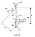
- FIGS. 2A-Cdepict the bottom of an illustrative electrical connector in a narrow configuration in bottom, close-up, and isometric views, respectively.
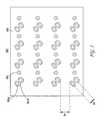
- FIG. 3depicts a illustrative circuit board layout for a narrow configuration.
- FIGS. 4A-Cdepict the bottom of an illustrative electrical connector in a wide configuration in bottom, close-up, and isometric views, respectively.
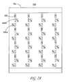
- FIG. 5depicts a illustrative circuit board layout for a wide configuration.
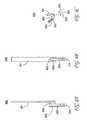
- FIGS. 6A-Cdepict an illustrative electrical contact in front, side, and bottom views, respectively.
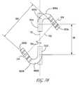
- FIG. 7A-Bdepicts the bottom of an illustrative electrical connector in an intermediate configuration in bottom and close-up views, respectively.
- One aspect of the present inventionis the ability to change, tune, or otherwise change the characteristic impedance of an orthogonal printed circuit board connector footprint and maintain differential coupling through a connector housing. This can be accomplished by keeping most of the connector the same, but change the configuration, relative spacing, or orientation of the mounting portions of the differential signal pairs. In a first configuration, such as shown in FIG. 2A , the mounting portions are closer together, which increases capacitive coupling and lowers the impedance. In a second configuration, such as shown in FIG. 4A , the mounting portions are spaced farther apart, which raises the impedance as compared to the FIG. 2A embodiment. In a third configuration, such as shown in FIG. 7A , the impedance can be adjusted between the FIG. 2A embodiment and the FIG. 7A embodiment.
- a method to adjust electrical characteristics of an orthogonal printed circuit board connector footprintmay comprise the steps of making a first electrical connector comprising two electrically-conductive contacts aligned edge to edge to define a differential signal pair and separated from one another by a first distance, making a second electrical connector comprising two second electrically-conductive contacts aligned edge to edge or broadside to broadside to define a second differential signal pair and also separated from one another by the first distance, offsetting mounting portions of the two electrically-conductive contacts a first distance with respect to each other to form a first connector footprint that corresponds to a first substrate footprint with a first impedance and offsetting second mounting portions of the two second electrically-conductive contacts a second distance with respect to each other to form a second connector footprint that is different than the first connector footprint and corresponds to a second substrate footprint with a second impedance that is different than the first impedance.
- the methodmay also include the step of making a third electrical connector that mates with both the first electrical connector and the second electrical connector.
- the step of offsetting the second mounting portions of the two second electrically-conductive contacts the second distancemay further comprise the steps of arranging the second mounting portions at a forty-five degree angle with respect to a centerline passing coincident with lead portions of the two electrically-conductive contacts, spacing the second mounting portions farther apart than the first distance, and/or rotating each of the two second electrically-conductive contacts 180 degrees with respect to the orientation of respective ones of the two electrically-conductive contacts.
- FIGS. 1A and 1Bdepict an illustrative electrical contact 100 in front and side views, respectively.
- the contactmay include a lead portion 101 connected to an offset portion 102 .
- the contactmay include a mounting portion 103 also connected to the offset portion 102 .
- the mounting portion 103may define a distal tip 104 .
- the contact 100may be made of an electrical conductive material such as metal.
- the contact 100may be manufactured by stamping and bending metal into the desired shape.
- the lead portion 101may extend from one end of the offset portion 102 .
- the mounting portion 103may extend from the other end of the offset portion 102 .
- the lead portion 101 and the mounting portion 103may extend in opposite directions.
- the lead portion 101 and the mounting portion 103may each define a longitudinal axis.
- the offset portion 102may define the distance between the two axes.
- the offset portion 102may be straight or curved.
- the length and the shape of the offset portion 102may define the distance and relative position of the two axes.
- the offset portion 102may extend from the end of the lead portion 101 in a first direction orthogonal to the longitudinal axis of the lead portion 101 .
- the offset portion 102may extend from the mounting portion 103 in a second direction orthogonal to the longitudinal axis of the mounting portion.
- the mounting portion 103may be suitable for mounting to a substrate, such as a circuit board, for example.
- the mounting portion 103may be an eye-of-the-needle configuration suitable for securing into vias within the circuit board.
- the mounting portion 103may be suitable for a ball grid array (BGA).
- BGAball grid array
- the lead portion 101may be suitable for establishing an conductive connection with a complementary contact.
- the lead portion 101may be a plug contact or a receptacle contact.
- the lead portion 101 and the mounting portion 103may each define an imaginary plane.
- the two imaginary planesmay intersect.
- the two imaginary planesmay intersect at a right angle.
- the two imaginary planesmay intersect at a non-right angle.
- the non-right anglemay be an acute angle or an obtuse angle.
- two instances of the contact 100may be arranged in a signal pair in an electrical connector. While the orientation of the respective mounting portions relative to the respective lead portions may be suitable for an orthogonal application, the distance between the respective mounting portions may be selected independent of the distance between the respective lead portions.
- the signal pairmay be employed in narrow, wide, or variable configurations.
- FIGS. 2A-Cdepict the bottom of an illustrative electrical connector 200 in a narrow configuration in bottom, close-up, and isometric views, respectively.
- Each contact 100 A-B within the signal pairmay face toward each other.
- the first contact 100 A of the signal pairmay be rotated 180° with respect to the second contact 101 B of the signal pair such that their respective mounting portions 103 A-B are between the respective lead portions 101 A-B in a narrow configuration.
- the connector 200may be suitable for an orthogonal application.
- the connector 200may include signal contacts 100 A-B and ground contacts 202 secured within a connector housing 201 .
- the connector housing 201may be made of any non-conductive material.
- the housing 201may be made from plastic.
- the connector housing 201may have a mounting side and a mating side.
- the mating side(not shown) may be suitable for engaging a complementary connector.
- the mounting side 205may be suitable for mounting the connector 200 to a circuit board.
- the mounting portion 103 A-B of each contact 100 A-Bmay extend through the mounting side 205 of the connector housing 201 .
- the offset portion (not shown) of each contact 100 A-Bmay be flush to the mounting side 205 of the connector housing 201 .
- the offset portion (not shown) of each contact 100 A-Bmay be flush to the upper surface of the circuit board better maintaining impedance through the connector and reducing the amount of impedance mismatch.
- each signal contact 100 A-B and each ground contact 202may be arranged in rows and columns. Each signal contact 100 A-B may be grouped into differential signal pairs. The distance between the lead portions 101 A-B of each contact may be defined as the contact pitch.
- the connector 200may enable the lead portion 101 A-B of each contact 100 A-B to be oriented at a substantially 45° angle from the respective mounting portions 103 A-B.
- an imaginary contact plane 111may align the lead portion 101 A of the first contact 100 A and the lead portion 101 B of the second contact 100 B.
- An imaginary line 112may extend from the distal tip 104 A of the mounting portion 103 A of the first contact 100 A to distal tip 104 B of the mounting portion 103 B of the second contact 100 B.
- the contact plane and the imaginary linemay interest at an angle 110 .
- the angle 110 measured normal to the contact planemay be substantially 45°.
- the anglemay be substantially 45° within manufacturing tolerance.
- Distance D 1may be defined as the distance measured along the contact plane between the center of the lead portion 101 A of the first contact 100 A and the center of the lead portion 101 B of the second contact 100 B. Distance D 1 may measure the contact pitch as measured center-to-center.
- Distance D 2may be defined as the length of the imaginary line 112 .
- Distance D 2may be selected independent of distance D 2 such that the angle 110 is maintained.
- the distance D 2may be selected according to signal integrity and/or physical design requirements, while maintaining the geometry suitable for orthogonal applications.
- distance D 2may be selected independent of distance D 1
- connectors of the same family, where contact pitch is defined for the connector familymay be manufactured for specific applications such that distance D 2 may be selected to match the impedance of a specific complementary electrical device.
- D 2may represent the minimum hole-to-hole spacing for an orthogonal application with a D 1 contact pitch. Such a configuration may allow for lower cross-talk, lower impedance, and wider area for trace routing.
- FIG. 3depicts a illustrative circuit board layout 300 for a narrow configuration.
- Vias 301 A-B, 302may be holes in the circuit board 305 oriented for mounting connector 200 .
- via 302may be a hole within the circuit board 305 that receives the mounting portion of the ground contact 202
- via 301 A-Bmay be a hole within the circuit board 305 that receives mounting portion 103 A-B of the signal contacts 100 A-B.
- the circuit board layout 300may define a distance D 3 between vias 301 A-B. Distance D 3 may match the distance D 2 . It may be desirable to select D 3 on the basis of signal integrity. For example, it may be desirable to select D 3 on the basis of impedance matching.
- the circuit board layout 305may define a distance D 4 between rows of vias 301 A-B.
- Distance D 4may provide a width of circuit board that may be used for conductive traces (not shown). It may be desirable to select distance D 4 to ensure adequate physical space for conductive traces. Accordingly, design requirements that influence distance D 3 and distance D 4 may reflect various implementations for distance D 2 of the electrical connector.
- FIGS. 4A and 4Bdepict the bottom of an illustrative electrical connector 400 in a wide configuration in isometric and bottom views, respectively.
- Signal contacts 100 A-B and ground contacts 202may be secured within a connector housing 404 .
- each contact 100 A-B within the signal pairmay face away from each other.
- the first contact 100 A of the signal pairmay be rotated 180° with respect to the second contact 100 B of the signal pair such that their respective lead portions 101 A-B are between the respective mounting portions 101 A-B in a wide configuration.
- the connector 400may enable the lead portion 101 A-B of each contact 100 A-B to be oriented at a substantially 45° angle from the respective mounting portions 103 A-B.
- an imaginary contact plane 411may align the lead portion 101 A of the first contact 100 A and the lead portion 101 B of the second contact 100 B.
- An imaginary line 412may extend from the distal tip 104 A of the mounting portion 103 A of the first contact 100 A to distal tip 104 B of the mounting portion 103 B of the second contact 100 B.
- the contact plane and the imaginary linemay interest at an angle 410 .
- the angle 410 measured normal to the contact planemay be substantially 45°.
- the anglemay be substantially 45° within manufacturing tolerance.
- Distance D 5may be defined as the distance measured along the contact plane between the center of the lead portion 101 A of the first contact 100 A and the center of the lead portion 101 B of the second contact 100 B. Distance D 5 may measure the contact pitch as measured center-to-center.
- Distance D 6may be defined as the length of the imaginary line 412 .
- Distance D 6may be selected independent of distance D 5 such that the angle 110 is maintained.
- the distance D 6may be selected according to signal integrity and/or physical design requirements, while maintaining the geometry suitable for orthogonal applications.
- connectors of the same family, where contact pitch is defined for the connector familymay be manufactured for specific applications such that distance D 6 may be selected to match the impedance of a specific complementary electrical device.
- D 6may represent the maximum hole-to-hole spacing for an orthogonal application with a D 5 contact pitch. Such a configuration may increase impedance.
- FIG. 5depicts a illustrative circuit board layout 500 for a wide configuration.
- 502may holes in the circuit board 505 oriented for mounting connector 400 .
- via 502may be a hole within the circuit board 505 that receives the mounting portion of the ground contact 202
- via 501 A-Bmay be a hole within the circuit board 505 that receives mounting portion 103 A-B of the signal contacts 100 A-B.
- the circuit board layout 500may define a distance D 7 between vias 501 A-B. Distance D 7 may match the distance D 6 . It may be desirable to select D 7 on the basis of signal integrity. For example, it may be desirable to select D 7 on the basis of impedance matching.
- the circuit board layout 505may define a distance D 8 between rows of vias 501 A-B.
- Distance D 8may provide a width of circuit board that may be used for conductive traces (not shown). It may be desirable to select D 8 to ensure adequate physical space for conductive traces. Accordingly, design requirements that influence distance D 7 and distance D 8 may reflect various implementations for distance D 6 of the electrical connector.
- FIGS. 6A and 6Bdepict an illustrative electrical contact 600 in front, side, and bottom views respectively.
- the contact 600may be used for a variable width configuration.
- the contactmay include a lead portion 101 connected to an offset portion 602 .
- the offset portion 602may define a distal end 603 .
- a mounting portion 103may extend from the distal end 603 of the offset portion 602 .
- the lead portion 101 and the mounting portion 103may each define a longitudinal axis.
- the offset portion 602may define the distance and relative position of the two axes.
- the offset portion 602may be curved.
- the lead portion 101may extend in a direction opposite the direction that the mounting portion 103 extends.
- the lead portion 101may define a first imaginary plane 621 .
- the distal end 603 of the offset portion 602may define a second imaginary plane 622 .
- the first imaginary plane 621 and the second imaginary plane 622may intersect at an angle 623 .
- the angle 623may be a non-right, acute angle, for example.
- FIG. 7A-Bdepicts the bottom of an illustrative electrical connector 700 in an intermediate configuration in bottom and close-up views, respectively.
- Signal contacts 600 A-B and ground contacts 202may be secured within a connector housing 701 .
- the connector 700may enable the lead portion 101 A-B of each contact 100 A-B to be oriented at a substantially 45° angle from the respective mounting portions 103 A-B.
- an imaginary contact plane 711may align the lead portion 101 A of the first contact 100 A and the lead portion 101 B of the second contact 100 B.
- An imaginary line 712may extend from the distal tip 104 A of the mounting portion 103 A of the first contact 100 A to distal tip 104 B of the mounting portion 103 B of the second contact 100 B.
- the contact plane and the imaginary linemay interest at an angle 710 .
- the angle 710 measured normal to the contact planemay be substantially 45°.
- the anglemay be substantially 45° within manufacturing tolerance.
- Distance D 9may be defined as the distance measured along the contact plane between the center of the lead portion 101 A of the first contact 100 A and the center of the lead portion 101 B of the second contact 100 B. Distance D 9 may measure the contact pitch as measured center-to-center.
- Distance D 10may be defined as the length of the imaginary line 712 .
- Distance D 9may be selected independent of distance D 10 such that the angle 710 is maintained.
- the distance D 10may be selected according to signal integrity and/or physical design requirements, while maintaining the geometry suitable for orthogonal applications. Because distance D 10 may be selected independent of distance D 9 , connectors of the same family, where contact pitch is defined for the connector family, may be manufactured for specific applications such that distance D 10 may be selected to match the impedance of a specific complementary electrical device. D 10 may be selected to be greater than, equal to, or less than D 9 .
- D 10may represent an intermediate hole-to-hole spacing.
- D 10may be changed by varying the offset portion 602 , resulting in variations in impedance, cross-talk, and routing channel width independent of the contact pitch D 9 .
Landscapes
- Details Of Connecting Devices For Male And Female Coupling (AREA)
- Coupling Device And Connection With Printed Circuit (AREA)
Abstract
Description
Claims (13)
Priority Applications (1)
| Application Number | Priority Date | Filing Date | Title |
|---|---|---|---|
| US12/528,906US8057267B2 (en) | 2007-02-28 | 2008-02-26 | Orthogonal header |
Applications Claiming Priority (4)
| Application Number | Priority Date | Filing Date | Title |
|---|---|---|---|
| US11680210 | 2007-02-28 | ||
| US11/680,210US7422444B1 (en) | 2007-02-28 | 2007-02-28 | Orthogonal header |
| US12/528,906US8057267B2 (en) | 2007-02-28 | 2008-02-26 | Orthogonal header |
| PCT/US2008/002476WO2008106096A1 (en) | 2007-02-28 | 2008-02-26 | Orthogonal header |
Related Parent Applications (2)
| Application Number | Title | Priority Date | Filing Date |
|---|---|---|---|
| US11/680,210Continuation-In-PartUS7422444B1 (en) | 2007-02-28 | 2007-02-28 | Orthogonal header |
| PCT/US2008/002476A-371-Of-InternationalWO2008106096A1 (en) | 2007-02-28 | 2008-02-26 | Orthogonal header |
Related Child Applications (1)
| Application Number | Title | Priority Date | Filing Date |
|---|---|---|---|
| US12/970,206DivisionUS7967647B2 (en) | 2007-02-28 | 2010-12-16 | Orthogonal header |
Publications (2)
| Publication Number | Publication Date |
|---|---|
| US20100048067A1 US20100048067A1 (en) | 2010-02-25 |
| US8057267B2true US8057267B2 (en) | 2011-11-15 |
Family
ID=39716007
Family Applications (3)
| Application Number | Title | Priority Date | Filing Date |
|---|---|---|---|
| US11/680,210ActiveUS7422444B1 (en) | 2007-02-28 | 2007-02-28 | Orthogonal header |
| US12/528,906ActiveUS8057267B2 (en) | 2007-02-28 | 2008-02-26 | Orthogonal header |
| US12/970,206Expired - Fee RelatedUS7967647B2 (en) | 2007-02-28 | 2010-12-16 | Orthogonal header |
Family Applications Before (1)
| Application Number | Title | Priority Date | Filing Date |
|---|---|---|---|
| US11/680,210ActiveUS7422444B1 (en) | 2007-02-28 | 2007-02-28 | Orthogonal header |
Family Applications After (1)
| Application Number | Title | Priority Date | Filing Date |
|---|---|---|---|
| US12/970,206Expired - Fee RelatedUS7967647B2 (en) | 2007-02-28 | 2010-12-16 | Orthogonal header |
Country Status (3)
| Country | Link |
|---|---|
| US (3) | US7422444B1 (en) |
| CN (2) | CN101622914B (en) |
| WO (1) | WO2008106096A1 (en) |
Cited By (36)
| Publication number | Priority date | Publication date | Assignee | Title |
|---|---|---|---|---|
| US8784116B2 (en) | 2011-04-04 | 2014-07-22 | Fci Americas Technology Llc | Electrical connector |
| US9308636B2 (en) | 2012-02-03 | 2016-04-12 | Milwaukee Electric Tool Corporation | Rotary hammer with vibration dampening |
| US9450344B2 (en) | 2014-01-22 | 2016-09-20 | Amphenol Corporation | High speed, high density electrical connector with shielded signal paths |
| US9564696B2 (en) | 2008-01-17 | 2017-02-07 | Amphenol Corporation | Electrical connector assembly |
| US9685736B2 (en) | 2014-11-12 | 2017-06-20 | Amphenol Corporation | Very high speed, high density electrical interconnection system with impedance control in mating region |
| US10141676B2 (en) | 2015-07-23 | 2018-11-27 | Amphenol Corporation | Extender module for modular connector |
| US10305224B2 (en) | 2016-05-18 | 2019-05-28 | Amphenol Corporation | Controlled impedance edged coupled connectors |
| US10720735B2 (en) | 2016-10-19 | 2020-07-21 | Amphenol Corporation | Compliant shield for very high speed, high density electrical interconnection |
| WO2020236794A1 (en) | 2019-05-20 | 2020-11-26 | Amphenol Corporation | High density, high speed electrical connector |
| US10931062B2 (en) | 2018-11-21 | 2021-02-23 | Amphenol Corporation | High-frequency electrical connector |
| US10944189B2 (en) | 2018-09-26 | 2021-03-09 | Amphenol East Asia Electronic Technology (Shenzhen) Co., Ltd. | High speed electrical connector and printed circuit board thereof |
| US10944214B2 (en) | 2017-08-03 | 2021-03-09 | Amphenol Corporation | Cable connector for high speed interconnects |
| WO2021154813A1 (en) | 2020-01-27 | 2021-08-05 | Amphenol Corporation | Electrical connector with high speed mounting interface |
| US11101611B2 (en) | 2019-01-25 | 2021-08-24 | Fci Usa Llc | I/O connector configured for cabled connection to the midboard |
| US11189943B2 (en) | 2019-01-25 | 2021-11-30 | Fci Usa Llc | I/O connector configured for cable connection to a midboard |
| US11205877B2 (en) | 2018-04-02 | 2021-12-21 | Ardent Concepts, Inc. | Controlled-impedance compliant cable termination |
| US11437762B2 (en) | 2019-02-22 | 2022-09-06 | Amphenol Corporation | High performance cable connector assembly |
| US11444398B2 (en) | 2018-03-22 | 2022-09-13 | Amphenol Corporation | High density electrical connector |
| US11444397B2 (en) | 2015-07-07 | 2022-09-13 | Amphenol Fci Asia Pte. Ltd. | Electrical connector with cavity between terminals |
| US11469554B2 (en) | 2020-01-27 | 2022-10-11 | Fci Usa Llc | High speed, high density direct mate orthogonal connector |
| US11522310B2 (en) | 2012-08-22 | 2022-12-06 | Amphenol Corporation | High-frequency electrical connector |
| US11539171B2 (en) | 2016-08-23 | 2022-12-27 | Amphenol Corporation | Connector configurable for high performance |
| US11670879B2 (en) | 2020-01-28 | 2023-06-06 | Fci Usa Llc | High frequency midboard connector |
| US11735852B2 (en) | 2019-09-19 | 2023-08-22 | Amphenol Corporation | High speed electronic system with midboard cable connector |
| US11757224B2 (en) | 2010-05-07 | 2023-09-12 | Amphenol Corporation | High performance cable connector |
| USD1002553S1 (en) | 2021-11-03 | 2023-10-24 | Amphenol Corporation | Gasket for connector |
| US11799246B2 (en) | 2020-01-27 | 2023-10-24 | Fci Usa Llc | High speed connector |
| US11817655B2 (en) | 2020-09-25 | 2023-11-14 | Amphenol Commercial Products (Chengdu) Co., Ltd. | Compact, high speed electrical connector |
| US11831106B2 (en) | 2016-05-31 | 2023-11-28 | Amphenol Corporation | High performance cable termination |
| US11942716B2 (en) | 2020-09-22 | 2024-03-26 | Amphenol Commercial Products (Chengdu) Co., Ltd. | High speed electrical connector |
| US11950356B2 (en) | 2014-11-21 | 2024-04-02 | Amphenol Corporation | Mating backplane for high speed, high density electrical connector |
| USD1067191S1 (en) | 2021-12-14 | 2025-03-18 | Amphenol Corporation | Electrical connector |
| USD1068685S1 (en) | 2021-12-14 | 2025-04-01 | Amphenol Corporation | Electrical connector |
| US12300936B2 (en) | 2019-02-19 | 2025-05-13 | Amphenol Corporation | High speed connector |
| US12300920B2 (en) | 2021-08-13 | 2025-05-13 | Amphenol Commercial Products (Chengdu) Co., Ltd. | High performance card edge connector for high bandwidth transmission |
| US12444863B2 (en) | 2023-04-24 | 2025-10-14 | Amphenol Corporation | Electrical connector with high speed mounting interface |
Families Citing this family (11)
| Publication number | Priority date | Publication date | Assignee | Title |
|---|---|---|---|---|
| US7422444B1 (en)* | 2007-02-28 | 2008-09-09 | Fci Americas Technology, Inc. | Orthogonal header |
| US7621781B2 (en) | 2007-03-20 | 2009-11-24 | Tyco Electronics Corporation | Electrical connector with crosstalk canceling features |
| JP5287753B2 (en)* | 2010-02-03 | 2013-09-11 | 株式会社デンソー | Electronic equipment |
| CN103563179B (en) | 2011-03-17 | 2016-09-07 | 莫列斯有限公司 | Connector and connector system |
| DE102011119274A1 (en)* | 2011-11-24 | 2013-05-29 | Erni Electronics Gmbh | Connector with shielding |
| CN109076700B (en)* | 2016-03-08 | 2021-07-30 | 安费诺公司 | Backplane footprint for high-speed, high-density electrical connectors |
| US11374360B2 (en) | 2016-08-23 | 2022-06-28 | Samtec, Inc. | Electrical contacts having anchoring regions with improved impedance characteristics |
| USD851044S1 (en) | 2016-09-30 | 2019-06-11 | Samtec, Inc. | Vertical electrical connector system |
| CN110800172B (en) | 2017-04-28 | 2021-06-04 | 富加宜(美国)有限责任公司 | High frequency BGA connector |
| KR102678838B1 (en)* | 2018-07-06 | 2024-06-27 | 샘텍, 인코포레이티드 | Connector with top- and bottom-stitched contacts |
| CN109818208B (en)* | 2019-03-21 | 2019-11-08 | 四川大学 | Connectors for high data transfer rates |
Citations (157)
| Publication number | Priority date | Publication date | Assignee | Title |
|---|---|---|---|---|
| US2664552A (en) | 1950-06-19 | 1953-12-29 | Ericsson Telefon Ab L M | Device for connection of cables by means of plugs and sockets |
| US2849700A (en) | 1956-06-22 | 1958-08-26 | Gen Telephone Company Of Calif | Telephone intercept bridge |
| US2858372A (en) | 1954-08-19 | 1958-10-28 | John M Kaufman | Interception block for telephone exchanges |
| US3115379A (en) | 1961-11-29 | 1963-12-24 | United Carr Fastener Corp | Electrical connector |
| US3286220A (en) | 1964-06-10 | 1966-11-15 | Amp Inc | Electrical connector means |
| US3343120A (en) | 1965-04-01 | 1967-09-19 | Wesley W Whiting | Electrical connector clip |
| US3482201A (en) | 1967-08-29 | 1969-12-02 | Thomas & Betts Corp | Controlled impedance connector |
| US3538486A (en) | 1967-05-25 | 1970-11-03 | Amp Inc | Connector device with clamping contact means |
| US3591834A (en) | 1969-12-22 | 1971-07-06 | Ibm | Circuit board connecting means |
| US3641475A (en) | 1969-12-18 | 1972-02-08 | Bell Telephone Labor Inc | Intercept connector for making alternative bridging connections having improved contact clip construction |
| US3663925A (en) | 1970-05-20 | 1972-05-16 | Us Navy | Electrical connector |
| US3669054A (en) | 1970-03-23 | 1972-06-13 | Amp Inc | Method of manufacturing electrical terminals |
| US3701076A (en) | 1969-12-18 | 1972-10-24 | Bell Telephone Labor Inc | Intercept connector having two diode mounting holes separated by a diode supporting recess |
| US3748633A (en) | 1972-01-24 | 1973-07-24 | Amp Inc | Square post connector |
| US3827005A (en) | 1973-05-09 | 1974-07-30 | Du Pont | Electrical connector |
| US3867008A (en) | 1972-08-25 | 1975-02-18 | Hubbell Inc Harvey | Contact spring |
| US4030792A (en) | 1976-03-01 | 1977-06-21 | Fabri-Tek Incorporated | Tuning fork connector |
| US4076362A (en) | 1976-02-20 | 1978-02-28 | Japan Aviation Electronics Industry Ltd. | Contact driver |
| US4159861A (en) | 1977-12-30 | 1979-07-03 | International Telephone And Telegraph Corporation | Zero insertion force connector |
| US4232924A (en) | 1978-10-23 | 1980-11-11 | Nanodata Corporation | Circuit card adapter |
| US4260212A (en) | 1979-03-20 | 1981-04-07 | Amp Incorporated | Method of producing insulated terminals |
| US4288139A (en) | 1979-03-06 | 1981-09-08 | Amp Incorporated | Trifurcated card edge terminal |
| US4383724A (en) | 1980-06-03 | 1983-05-17 | E. I. Du Pont De Nemours And Company | Bridge connector for electrically connecting two pins |
| US4402563A (en) | 1981-05-26 | 1983-09-06 | Aries Electronics, Inc. | Zero insertion force connector |
| US4482937A (en) | 1982-09-30 | 1984-11-13 | Control Data Corporation | Board to board interconnect structure |
| US4523296A (en) | 1983-01-03 | 1985-06-11 | Westinghouse Electric Corp. | Replaceable intermediate socket and plug connector for a solid-state data transfer system |
| US4560222A (en) | 1984-05-17 | 1985-12-24 | Molex Incorporated | Drawer connector |
| US4664458A (en) | 1985-09-19 | 1987-05-12 | C W Industries | Printed circuit board connector |
| US4717360A (en) | 1986-03-17 | 1988-01-05 | Zenith Electronics Corporation | Modular electrical connector |
| US4776803A (en) | 1986-11-26 | 1988-10-11 | Minnesota Mining And Manufacturing Company | Integrally molded card edge cable termination assembly, contact, machine and method |
| US4815987A (en) | 1986-12-26 | 1989-03-28 | Fujitsu Limited | Electrical connector |
| US4867713A (en) | 1987-02-24 | 1989-09-19 | Kabushiki Kaisha Toshiba | Electrical connector |
| US4898539A (en) | 1989-02-22 | 1990-02-06 | Amp Incorporated | Surface mount HDI contact |
| US4900271A (en) | 1989-02-24 | 1990-02-13 | Molex Incorporated | Electrical connector for fuel injector and terminals therefor |
| US4907990A (en) | 1988-10-07 | 1990-03-13 | Molex Incorporated | Elastically supported dual cantilever beam pin-receiving electrical contact |
| US4913664A (en) | 1988-11-25 | 1990-04-03 | Molex Incorporated | Miniature circular DIN connector |
| US4917616A (en) | 1988-07-15 | 1990-04-17 | Amp Incorporated | Backplane signal connector with controlled impedance |
| US4973271A (en) | 1989-01-30 | 1990-11-27 | Yazaki Corporation | Low insertion-force terminal |
| US4997390A (en) | 1989-06-29 | 1991-03-05 | Amp Incorporated | Shunt connector |
| US5004426A (en) | 1989-09-19 | 1991-04-02 | Teradyne, Inc. | Electrically connecting |
| US5046960A (en) | 1990-12-20 | 1991-09-10 | Amp Incorporated | High density connector system |
| US5055054A (en) | 1990-06-05 | 1991-10-08 | E. I. Du Pont De Nemours And Company | High density connector |
| US5065282A (en) | 1986-10-17 | 1991-11-12 | Polonio John D | Interconnection mechanisms for electronic components |
| US5066236A (en) | 1989-10-10 | 1991-11-19 | Amp Incorporated | Impedance matched backplane connector |
| US5077893A (en) | 1989-09-26 | 1992-01-07 | Molex Incorporated | Method for forming electrical terminal |
| US5094623A (en) | 1991-04-30 | 1992-03-10 | Thomas & Betts Corporation | Controlled impedance electrical connector |
| US5098311A (en) | 1989-06-12 | 1992-03-24 | Ohio Associated Enterprises, Inc. | Hermaphroditic interconnect system |
| US5127839A (en) | 1991-04-26 | 1992-07-07 | Amp Incorporated | Electrical connector having reliable terminals |
| US5163849A (en) | 1991-08-27 | 1992-11-17 | Amp Incorporated | Lead frame and electrical connector |
| US5167528A (en) | 1990-04-20 | 1992-12-01 | Matsushita Electric Works, Ltd. | Method of manufacturing an electrical connector |
| US5169337A (en) | 1991-09-05 | 1992-12-08 | Amp Incorporated | Electrical shunt |
| US5174770A (en) | 1990-11-15 | 1992-12-29 | Amp Incorporated | Multicontact connector for signal transmission |
| US5181855A (en) | 1991-10-03 | 1993-01-26 | Itt Corporation | Simplified contact connector system |
| US5238414A (en) | 1991-07-24 | 1993-08-24 | Hirose Electric Co., Ltd. | High-speed transmission electrical connector |
| US5254012A (en) | 1992-08-21 | 1993-10-19 | Industrial Technology Research Institute | Zero insertion force socket |
| US5257941A (en) | 1991-08-15 | 1993-11-02 | E. I. Du Pont De Nemours And Company | Connector and electrical connection structure using the same |
| US5274918A (en) | 1993-04-15 | 1994-01-04 | The Whitaker Corporation | Method for producing contact shorting bar insert for modular jack assembly |
| US5286212A (en) | 1992-03-09 | 1994-02-15 | The Whitaker Corporation | Shielded back plane connector |
| US5288949A (en) | 1992-02-03 | 1994-02-22 | Ncr Corporation | Connection system for integrated circuits which reduces cross-talk |
| US5302135A (en) | 1993-02-09 | 1994-04-12 | Lee Feng Jui | Electrical plug |
| US5342211A (en) | 1992-03-09 | 1994-08-30 | The Whitaker Corporation | Shielded back plane connector |
| US5356300A (en) | 1993-09-16 | 1994-10-18 | The Whitaker Corporation | Blind mating guides with ground contacts |
| US5357050A (en) | 1992-11-20 | 1994-10-18 | Ast Research, Inc. | Apparatus and method to reduce electromagnetic emissions in a multi-layer circuit board |
| US5387111A (en) | 1993-10-04 | 1995-02-07 | Motorola, Inc. | Electrical connector |
| US5395250A (en) | 1994-01-21 | 1995-03-07 | The Whitaker Corporation | Low profile board to board connector |
| US5429520A (en) | 1993-06-04 | 1995-07-04 | Framatome Connectors International | Connector assembly |
| US5431578A (en) | 1994-03-02 | 1995-07-11 | Abrams Electronics, Inc. | Compression mating electrical connector |
| US5475922A (en) | 1992-12-18 | 1995-12-19 | Fujitsu Ltd. | Method of assembling a connector using frangible contact parts |
| US5522727A (en) | 1993-09-17 | 1996-06-04 | Japan Aviation Electronics Industry, Limited | Electrical angle connector of a printed circuit board type having a plurality of connecting conductive strips of a common length |
| US5558542A (en) | 1995-09-08 | 1996-09-24 | Molex Incorporated | Electrical connector with improved terminal-receiving passage means |
| US5575688A (en) | 1992-12-01 | 1996-11-19 | Crane, Jr.; Stanford W. | High-density electrical interconnect system |
| US5586914A (en) | 1995-05-19 | 1996-12-24 | The Whitaker Corporation | Electrical connector and an associated method for compensating for crosstalk between a plurality of conductors |
| US5586908A (en) | 1993-09-08 | 1996-12-24 | U.S. Philips Corporation | Safety unit for an electric 3-phase circuit |
| US5590463A (en) | 1995-07-18 | 1997-01-07 | Elco Corporation | Circuit board connectors |
| US5609502A (en) | 1995-03-31 | 1997-03-11 | The Whitaker Corporation | Contact retention system |
| US5634821A (en) | 1992-12-01 | 1997-06-03 | Crane, Jr.; Stanford W. | High-density electrical interconnect system |
| US5637019A (en) | 1994-11-14 | 1997-06-10 | The Panda Project | Electrical interconnect system having insulative shrouds for preventing mismating |
| US5672064A (en) | 1995-12-21 | 1997-09-30 | Teradyne, Inc. | Stiffener for electrical connector |
| US5697799A (en) | 1996-07-31 | 1997-12-16 | The Whitaker Corporation | Board-mountable shielded electrical connector |
| US5730609A (en) | 1995-04-28 | 1998-03-24 | Molex Incorporated | High performance card edge connector |
| US5741161A (en) | 1996-01-04 | 1998-04-21 | Pcd Inc. | Electrical connection system with discrete wire interconnections |
| US5741144A (en) | 1995-06-12 | 1998-04-21 | Berg Technology, Inc. | Low cross and impedance controlled electric connector |
| US5795191A (en) | 1996-09-11 | 1998-08-18 | Preputnick; George | Connector assembly with shielded modules and method of making same |
| US5817973A (en) | 1995-06-12 | 1998-10-06 | Berg Technology, Inc. | Low cross talk and impedance controlled electrical cable assembly |
| US5833475A (en) | 1993-12-21 | 1998-11-10 | Berg Technology, Inc. | Electrical connector with an element which positions the connection pins |
| US5860816A (en) | 1996-03-28 | 1999-01-19 | Teradyne, Inc. | Electrical connector assembled from wafers |
| US5871362A (en) | 1994-12-27 | 1999-02-16 | International Business Machines Corporation | Self-aligning flexible circuit connection |
| US5876222A (en) | 1997-11-07 | 1999-03-02 | Molex Incorporated | Electrical connector for printed circuit boards |
| US5887158A (en) | 1992-06-08 | 1999-03-23 | Quickturn Design Systems, Inc. | Switching midplane and interconnecting system for interconnecting large numbers of signals |
| US5893761A (en) | 1996-02-12 | 1999-04-13 | Siemens Aktiengesellschaft | Printed circuit board connector |
| US5902136A (en) | 1996-06-28 | 1999-05-11 | Berg Technology, Inc. | Electrical connector for use in miniaturized, high density, and high pin count applications and method of manufacture |
| US5904581A (en) | 1996-07-17 | 1999-05-18 | Minnesota Mining And Manufacturing Company | Electrical interconnection system and device |
| US5908333A (en) | 1997-07-21 | 1999-06-01 | Rambus, Inc. | Connector with integral transmission line bus |
| US5938479A (en) | 1997-04-02 | 1999-08-17 | Communications Systems, Inc. | Connector for reducing electromagnetic field coupling |
| US5961355A (en) | 1997-12-17 | 1999-10-05 | Berg Technology, Inc. | High density interstitial connector system |
| US5971817A (en) | 1995-09-27 | 1999-10-26 | Siemens Aktiengesellschaft | Contact spring for a plug-in connector |
| US5980321A (en) | 1997-02-07 | 1999-11-09 | Teradyne, Inc. | High speed, high density electrical connector |
| US5984690A (en) | 1996-11-12 | 1999-11-16 | Riechelmann; Bernd | Contactor with multiple redundant connecting paths |
| US5992953A (en) | 1996-03-08 | 1999-11-30 | Rabinovitz; Josef | Adjustable interlocking system for computer peripheral and other desktop enclosures |
| US5993259A (en) | 1997-02-07 | 1999-11-30 | Teradyne, Inc. | High speed, high density electrical connector |
| US6022227A (en) | 1998-12-18 | 2000-02-08 | Hon Hai Precision Ind. Co., Ltd. | Electrical connector |
| US6042427A (en) | 1998-06-30 | 2000-03-28 | Lucent Technologies Inc. | Communication plug having low complementary crosstalk delay |
| US6050862A (en) | 1997-05-20 | 2000-04-18 | Yazaki Corporation | Female terminal with flexible contact area having inclined free edge portion |
| US6086386A (en) | 1996-05-24 | 2000-07-11 | Tessera, Inc. | Flexible connectors for microelectronic elements |
| US6116926A (en) | 1999-04-21 | 2000-09-12 | Berg Technology, Inc. | Connector for electrical isolation in a condensed area |
| US6179663B1 (en) | 1998-04-29 | 2001-01-30 | Litton Systems, Inc. | High density electrical interconnect system having enhanced grounding and cross-talk reduction capability |
| US6227882B1 (en) | 1997-10-01 | 2001-05-08 | Berg Technology, Inc. | Connector for electrical isolation in a condensed area |
| US6293827B1 (en) | 2000-02-03 | 2001-09-25 | Teradyne, Inc. | Differential signal electrical connector |
| US6302711B1 (en) | 1997-09-08 | 2001-10-16 | Taiko Denki Co., Ltd. | Printed board connector having contacts with bent terminal portions extending into an under space of the connector housing |
| US6328602B1 (en) | 1999-06-17 | 2001-12-11 | Nec Corporation | Connector with less crosstalk |
| US6375478B1 (en) | 1999-06-18 | 2002-04-23 | Nec Corporation | Connector well fit with printed circuit board |
| US6414248B1 (en) | 2000-10-04 | 2002-07-02 | Honeywell International Inc. | Compliant attachment interface |
| US6464529B1 (en) | 1993-03-12 | 2002-10-15 | Cekan/Cdt A/S | Connector element for high-speed data communications |
| US6503103B1 (en) | 1997-02-07 | 2003-01-07 | Teradyne, Inc. | Differential signal electrical connectors |
| US6506076B2 (en) | 2000-02-03 | 2003-01-14 | Teradyne, Inc. | Connector with egg-crate shielding |
| US6528737B1 (en) | 2000-08-16 | 2003-03-04 | Nortel Networks Limited | Midplane configuration featuring surface contact connectors |
| US6540522B2 (en) | 2001-04-26 | 2003-04-01 | Tyco Electronics Corporation | Electrical connector assembly for orthogonally mating circuit boards |
| US6551140B2 (en) | 2001-05-09 | 2003-04-22 | Hon Hai Precision Ind. Co., Ltd. | Electrical connector having differential pair terminals with equal length |
| US6572409B2 (en) | 2000-12-28 | 2003-06-03 | Japan Aviation Electronics Industry, Limited | Connector having a ground member obliquely extending with respect to an arrangement direction of a number of contacts |
| US20030116857A1 (en) | 2001-12-26 | 2003-06-26 | Fujitsu Limited | Circuit substrate and method for fabricating the same |
| US6592381B2 (en) | 2001-01-25 | 2003-07-15 | Teradyne, Inc. | Waferized power connector |
| US6672907B2 (en) | 2000-05-02 | 2004-01-06 | Fci Americas Technology, Inc. | Connector |
| US6692272B2 (en) | 2001-11-14 | 2004-02-17 | Fci Americas Technology, Inc. | High speed electrical connector |
| US6695627B2 (en) | 2001-08-02 | 2004-02-24 | Fci Americas Technnology, Inc. | Profiled header ground pin |
| US6736664B2 (en) | 2001-07-06 | 2004-05-18 | Yazaki Corporation | Piercing terminal and machine and method for crimping piercing terminal |
| US6746278B2 (en) | 2001-11-28 | 2004-06-08 | Molex Incorporated | Interstitial ground assembly for connector |
| US6749439B1 (en) | 2000-07-05 | 2004-06-15 | Network Engineers, Inc. | Circuit board riser |
| US6764341B2 (en) | 2001-05-25 | 2004-07-20 | Erni Elektroapparate Gmbh | Plug connector that can be turned by 90° |
| US6808420B2 (en) | 2002-05-22 | 2004-10-26 | Tyco Electronics Corporation | High speed electrical connector |
| US20040224559A1 (en) | 2002-12-04 | 2004-11-11 | Nelson Richard A. | High-density connector assembly with tracking ground structure |
| US20040235321A1 (en) | 2001-05-23 | 2004-11-25 | Akinori Mizumura | Board connecting connector and method for producing same |
| US6833615B2 (en) | 2000-12-29 | 2004-12-21 | Intel Corporation | Via-in-pad with off-center geometry |
| US6843686B2 (en) | 2002-04-26 | 2005-01-18 | Honda Tsushin Kogyo Co., Ltd. | High-frequency electric connector having no ground terminals |
| US6848944B2 (en) | 2001-11-12 | 2005-02-01 | Fci Americas Technology, Inc. | Connector for high-speed communications |
| US20050032401A1 (en) | 2003-08-08 | 2005-02-10 | Sumitomo Wiring Systems, Ltd. | Electrical junction box having an inspection section of a slit width of a tuning fork-like terminal |
| US6893686B2 (en) | 2002-01-31 | 2005-05-17 | Exopack, L.L.C. | Non-fluorocarbon oil and grease barrier methods of application and packaging |
| US6918789B2 (en) | 2002-05-06 | 2005-07-19 | Molex Incorporated | High-speed differential signal connector particularly suitable for docking applications |
| US20050170700A1 (en) | 2001-11-14 | 2005-08-04 | Shuey Joseph B. | High speed electrical connector without ground contacts |
| US20050196987A1 (en) | 2001-11-14 | 2005-09-08 | Shuey Joseph B. | High density, low noise, high speed mezzanine connector |
| US6945796B2 (en) | 1999-07-16 | 2005-09-20 | Molex Incorporated | Impedance-tuned connector |
| US20050215121A1 (en) | 2004-03-29 | 2005-09-29 | Takashi Tokunaga | Connector to be mounted to a board and ground structure of the connector |
| US20050227552A1 (en) | 2004-03-31 | 2005-10-13 | Autonetworks Technologies, Ltd. | Electrical connection box |
| US6981883B2 (en) | 2001-11-14 | 2006-01-03 | Fci Americas Technology, Inc. | Impedance control in electrical connectors |
| US20060024983A1 (en) | 2004-07-01 | 2006-02-02 | Cohen Thomas S | Differential electrical connector assembly |
| US6994569B2 (en) | 2001-11-14 | 2006-02-07 | Fci America Technology, Inc. | Electrical connectors having contacts that may be selectively designated as either signal or ground contacts |
| US20060068641A1 (en) | 2003-09-26 | 2006-03-30 | Hull Gregory A | Impedance mathing interface for electrical connectors |
| US7021975B2 (en) | 2003-05-13 | 2006-04-04 | Erni Elektroapparate Gmbh | Plug-in connector |
| US20060073709A1 (en) | 2004-10-06 | 2006-04-06 | Teradyne, Inc. | High density midplane |
| US7108556B2 (en) | 2004-07-01 | 2006-09-19 | Amphenol Corporation | Midplane especially applicable to an orthogonal architecture electronic system |
| US20060228912A1 (en) | 2005-04-07 | 2006-10-12 | Fci Americas Technology, Inc. | Orthogonal backplane connector |
| US20060232301A1 (en) | 2004-11-29 | 2006-10-19 | Fci Americas Technology, Inc. | Matched-impedance surface-mount technology footprints |
| US7239526B1 (en) | 2004-03-02 | 2007-07-03 | Xilinx, Inc. | Printed circuit board and method of reducing crosstalk in a printed circuit board |
| US7331802B2 (en) | 2005-11-02 | 2008-02-19 | Tyco Electronics Corporation | Orthogonal connector |
| US7331830B2 (en) | 2006-03-03 | 2008-02-19 | Fci Americas Technology, Inc. | High-density orthogonal connector |
| US7344391B2 (en) | 2006-03-03 | 2008-03-18 | Fci Americas Technology, Inc. | Edge and broadside coupled connector |
| US7422444B1 (en)* | 2007-02-28 | 2008-09-09 | Fci Americas Technology, Inc. | Orthogonal header |
| US7448909B2 (en) | 2004-02-13 | 2008-11-11 | Molex Incorporated | Preferential via exit structures with triad configuration for printed circuit boards |
Family Cites Families (2)
| Publication number | Priority date | Publication date | Assignee | Title |
|---|---|---|---|---|
| JP4494658B2 (en)* | 2001-02-06 | 2010-06-30 | 三菱重工業株式会社 | Gas turbine stationary blade shroud |
| US6883615B2 (en)* | 2002-01-23 | 2005-04-26 | Robert W. Coulombe | Gripping device and method for protecting the hoof of a horse from concussive forces |
- 2007
- 2007-02-28USUS11/680,210patent/US7422444B1/enactiveActive
- 2008
- 2008-02-26WOPCT/US2008/002476patent/WO2008106096A1/enactiveApplication Filing
- 2008-02-26CNCN2008800065155Apatent/CN101622914B/ennot_activeExpired - Fee Related
- 2008-02-26USUS12/528,906patent/US8057267B2/enactiveActive
- 2008-02-26CNCN2011100692672Apatent/CN102222822A/enactivePending
- 2010
- 2010-12-16USUS12/970,206patent/US7967647B2/ennot_activeExpired - Fee Related
Patent Citations (168)
| Publication number | Priority date | Publication date | Assignee | Title |
|---|---|---|---|---|
| US2664552A (en) | 1950-06-19 | 1953-12-29 | Ericsson Telefon Ab L M | Device for connection of cables by means of plugs and sockets |
| US2858372A (en) | 1954-08-19 | 1958-10-28 | John M Kaufman | Interception block for telephone exchanges |
| US2849700A (en) | 1956-06-22 | 1958-08-26 | Gen Telephone Company Of Calif | Telephone intercept bridge |
| US3115379A (en) | 1961-11-29 | 1963-12-24 | United Carr Fastener Corp | Electrical connector |
| US3286220A (en) | 1964-06-10 | 1966-11-15 | Amp Inc | Electrical connector means |
| US3343120A (en) | 1965-04-01 | 1967-09-19 | Wesley W Whiting | Electrical connector clip |
| US3538486A (en) | 1967-05-25 | 1970-11-03 | Amp Inc | Connector device with clamping contact means |
| US3482201A (en) | 1967-08-29 | 1969-12-02 | Thomas & Betts Corp | Controlled impedance connector |
| US3701076A (en) | 1969-12-18 | 1972-10-24 | Bell Telephone Labor Inc | Intercept connector having two diode mounting holes separated by a diode supporting recess |
| US3641475A (en) | 1969-12-18 | 1972-02-08 | Bell Telephone Labor Inc | Intercept connector for making alternative bridging connections having improved contact clip construction |
| US3591834A (en) | 1969-12-22 | 1971-07-06 | Ibm | Circuit board connecting means |
| US3669054A (en) | 1970-03-23 | 1972-06-13 | Amp Inc | Method of manufacturing electrical terminals |
| US3663925A (en) | 1970-05-20 | 1972-05-16 | Us Navy | Electrical connector |
| US3748633A (en) | 1972-01-24 | 1973-07-24 | Amp Inc | Square post connector |
| US3867008A (en) | 1972-08-25 | 1975-02-18 | Hubbell Inc Harvey | Contact spring |
| US3827005A (en) | 1973-05-09 | 1974-07-30 | Du Pont | Electrical connector |
| US4076362A (en) | 1976-02-20 | 1978-02-28 | Japan Aviation Electronics Industry Ltd. | Contact driver |
| US4030792A (en) | 1976-03-01 | 1977-06-21 | Fabri-Tek Incorporated | Tuning fork connector |
| US4159861A (en) | 1977-12-30 | 1979-07-03 | International Telephone And Telegraph Corporation | Zero insertion force connector |
| US4232924A (en) | 1978-10-23 | 1980-11-11 | Nanodata Corporation | Circuit card adapter |
| US4288139A (en) | 1979-03-06 | 1981-09-08 | Amp Incorporated | Trifurcated card edge terminal |
| US4260212A (en) | 1979-03-20 | 1981-04-07 | Amp Incorporated | Method of producing insulated terminals |
| US4383724A (en) | 1980-06-03 | 1983-05-17 | E. I. Du Pont De Nemours And Company | Bridge connector for electrically connecting two pins |
| US4402563A (en) | 1981-05-26 | 1983-09-06 | Aries Electronics, Inc. | Zero insertion force connector |
| US4482937A (en) | 1982-09-30 | 1984-11-13 | Control Data Corporation | Board to board interconnect structure |
| US4523296A (en) | 1983-01-03 | 1985-06-11 | Westinghouse Electric Corp. | Replaceable intermediate socket and plug connector for a solid-state data transfer system |
| US4560222A (en) | 1984-05-17 | 1985-12-24 | Molex Incorporated | Drawer connector |
| US4664458A (en) | 1985-09-19 | 1987-05-12 | C W Industries | Printed circuit board connector |
| US4717360A (en) | 1986-03-17 | 1988-01-05 | Zenith Electronics Corporation | Modular electrical connector |
| US5065282A (en) | 1986-10-17 | 1991-11-12 | Polonio John D | Interconnection mechanisms for electronic components |
| US4776803A (en) | 1986-11-26 | 1988-10-11 | Minnesota Mining And Manufacturing Company | Integrally molded card edge cable termination assembly, contact, machine and method |
| US4815987A (en) | 1986-12-26 | 1989-03-28 | Fujitsu Limited | Electrical connector |
| US4867713A (en) | 1987-02-24 | 1989-09-19 | Kabushiki Kaisha Toshiba | Electrical connector |
| US4917616A (en) | 1988-07-15 | 1990-04-17 | Amp Incorporated | Backplane signal connector with controlled impedance |
| US4907990A (en) | 1988-10-07 | 1990-03-13 | Molex Incorporated | Elastically supported dual cantilever beam pin-receiving electrical contact |
| US4913664A (en) | 1988-11-25 | 1990-04-03 | Molex Incorporated | Miniature circular DIN connector |
| US4973271A (en) | 1989-01-30 | 1990-11-27 | Yazaki Corporation | Low insertion-force terminal |
| US4898539A (en) | 1989-02-22 | 1990-02-06 | Amp Incorporated | Surface mount HDI contact |
| US4900271A (en) | 1989-02-24 | 1990-02-13 | Molex Incorporated | Electrical connector for fuel injector and terminals therefor |
| US5098311A (en) | 1989-06-12 | 1992-03-24 | Ohio Associated Enterprises, Inc. | Hermaphroditic interconnect system |
| US4997390A (en) | 1989-06-29 | 1991-03-05 | Amp Incorporated | Shunt connector |
| US5004426A (en) | 1989-09-19 | 1991-04-02 | Teradyne, Inc. | Electrically connecting |
| US5077893A (en) | 1989-09-26 | 1992-01-07 | Molex Incorporated | Method for forming electrical terminal |
| US5066236A (en) | 1989-10-10 | 1991-11-19 | Amp Incorporated | Impedance matched backplane connector |
| US5167528A (en) | 1990-04-20 | 1992-12-01 | Matsushita Electric Works, Ltd. | Method of manufacturing an electrical connector |
| US5055054A (en) | 1990-06-05 | 1991-10-08 | E. I. Du Pont De Nemours And Company | High density connector |
| US5174770A (en) | 1990-11-15 | 1992-12-29 | Amp Incorporated | Multicontact connector for signal transmission |
| US5046960A (en) | 1990-12-20 | 1991-09-10 | Amp Incorporated | High density connector system |
| US5127839A (en) | 1991-04-26 | 1992-07-07 | Amp Incorporated | Electrical connector having reliable terminals |
| US5094623A (en) | 1991-04-30 | 1992-03-10 | Thomas & Betts Corporation | Controlled impedance electrical connector |
| US5238414A (en) | 1991-07-24 | 1993-08-24 | Hirose Electric Co., Ltd. | High-speed transmission electrical connector |
| US5257941A (en) | 1991-08-15 | 1993-11-02 | E. I. Du Pont De Nemours And Company | Connector and electrical connection structure using the same |
| US5163849A (en) | 1991-08-27 | 1992-11-17 | Amp Incorporated | Lead frame and electrical connector |
| US5169337A (en) | 1991-09-05 | 1992-12-08 | Amp Incorporated | Electrical shunt |
| US5181855A (en) | 1991-10-03 | 1993-01-26 | Itt Corporation | Simplified contact connector system |
| US5288949A (en) | 1992-02-03 | 1994-02-22 | Ncr Corporation | Connection system for integrated circuits which reduces cross-talk |
| US5342211A (en) | 1992-03-09 | 1994-08-30 | The Whitaker Corporation | Shielded back plane connector |
| US5286212A (en) | 1992-03-09 | 1994-02-15 | The Whitaker Corporation | Shielded back plane connector |
| US5887158A (en) | 1992-06-08 | 1999-03-23 | Quickturn Design Systems, Inc. | Switching midplane and interconnecting system for interconnecting large numbers of signals |
| US5254012A (en) | 1992-08-21 | 1993-10-19 | Industrial Technology Research Institute | Zero insertion force socket |
| US5357050A (en) | 1992-11-20 | 1994-10-18 | Ast Research, Inc. | Apparatus and method to reduce electromagnetic emissions in a multi-layer circuit board |
| US5634821A (en) | 1992-12-01 | 1997-06-03 | Crane, Jr.; Stanford W. | High-density electrical interconnect system |
| US5575688A (en) | 1992-12-01 | 1996-11-19 | Crane, Jr.; Stanford W. | High-density electrical interconnect system |
| US5475922A (en) | 1992-12-18 | 1995-12-19 | Fujitsu Ltd. | Method of assembling a connector using frangible contact parts |
| US5302135A (en) | 1993-02-09 | 1994-04-12 | Lee Feng Jui | Electrical plug |
| US6464529B1 (en) | 1993-03-12 | 2002-10-15 | Cekan/Cdt A/S | Connector element for high-speed data communications |
| US5274918A (en) | 1993-04-15 | 1994-01-04 | The Whitaker Corporation | Method for producing contact shorting bar insert for modular jack assembly |
| US5429520A (en) | 1993-06-04 | 1995-07-04 | Framatome Connectors International | Connector assembly |
| US5586908A (en) | 1993-09-08 | 1996-12-24 | U.S. Philips Corporation | Safety unit for an electric 3-phase circuit |
| US5356300A (en) | 1993-09-16 | 1994-10-18 | The Whitaker Corporation | Blind mating guides with ground contacts |
| US5522727A (en) | 1993-09-17 | 1996-06-04 | Japan Aviation Electronics Industry, Limited | Electrical angle connector of a printed circuit board type having a plurality of connecting conductive strips of a common length |
| US5387111A (en) | 1993-10-04 | 1995-02-07 | Motorola, Inc. | Electrical connector |
| US5833475A (en) | 1993-12-21 | 1998-11-10 | Berg Technology, Inc. | Electrical connector with an element which positions the connection pins |
| US5395250A (en) | 1994-01-21 | 1995-03-07 | The Whitaker Corporation | Low profile board to board connector |
| US5431578A (en) | 1994-03-02 | 1995-07-11 | Abrams Electronics, Inc. | Compression mating electrical connector |
| US5637019A (en) | 1994-11-14 | 1997-06-10 | The Panda Project | Electrical interconnect system having insulative shrouds for preventing mismating |
| US5871362A (en) | 1994-12-27 | 1999-02-16 | International Business Machines Corporation | Self-aligning flexible circuit connection |
| US5609502A (en) | 1995-03-31 | 1997-03-11 | The Whitaker Corporation | Contact retention system |
| US5730609A (en) | 1995-04-28 | 1998-03-24 | Molex Incorporated | High performance card edge connector |
| US5586914A (en) | 1995-05-19 | 1996-12-24 | The Whitaker Corporation | Electrical connector and an associated method for compensating for crosstalk between a plurality of conductors |
| US5817973A (en) | 1995-06-12 | 1998-10-06 | Berg Technology, Inc. | Low cross talk and impedance controlled electrical cable assembly |
| US5741144A (en) | 1995-06-12 | 1998-04-21 | Berg Technology, Inc. | Low cross and impedance controlled electric connector |
| US5590463A (en) | 1995-07-18 | 1997-01-07 | Elco Corporation | Circuit board connectors |
| US5558542A (en) | 1995-09-08 | 1996-09-24 | Molex Incorporated | Electrical connector with improved terminal-receiving passage means |
| US5971817A (en) | 1995-09-27 | 1999-10-26 | Siemens Aktiengesellschaft | Contact spring for a plug-in connector |
| US5672064A (en) | 1995-12-21 | 1997-09-30 | Teradyne, Inc. | Stiffener for electrical connector |
| US5741161A (en) | 1996-01-04 | 1998-04-21 | Pcd Inc. | Electrical connection system with discrete wire interconnections |
| US5893761A (en) | 1996-02-12 | 1999-04-13 | Siemens Aktiengesellschaft | Printed circuit board connector |
| US5992953A (en) | 1996-03-08 | 1999-11-30 | Rabinovitz; Josef | Adjustable interlocking system for computer peripheral and other desktop enclosures |
| US5860816A (en) | 1996-03-28 | 1999-01-19 | Teradyne, Inc. | Electrical connector assembled from wafers |
| US6086386A (en) | 1996-05-24 | 2000-07-11 | Tessera, Inc. | Flexible connectors for microelectronic elements |
| US5902136A (en) | 1996-06-28 | 1999-05-11 | Berg Technology, Inc. | Electrical connector for use in miniaturized, high density, and high pin count applications and method of manufacture |
| US5904581A (en) | 1996-07-17 | 1999-05-18 | Minnesota Mining And Manufacturing Company | Electrical interconnection system and device |
| US5697799A (en) | 1996-07-31 | 1997-12-16 | The Whitaker Corporation | Board-mountable shielded electrical connector |
| US5795191A (en) | 1996-09-11 | 1998-08-18 | Preputnick; George | Connector assembly with shielded modules and method of making same |
| US5984690A (en) | 1996-11-12 | 1999-11-16 | Riechelmann; Bernd | Contactor with multiple redundant connecting paths |
| US6503103B1 (en) | 1997-02-07 | 2003-01-07 | Teradyne, Inc. | Differential signal electrical connectors |
| US5980321A (en) | 1997-02-07 | 1999-11-09 | Teradyne, Inc. | High speed, high density electrical connector |
| US5993259A (en) | 1997-02-07 | 1999-11-30 | Teradyne, Inc. | High speed, high density electrical connector |
| US6379188B1 (en) | 1997-02-07 | 2002-04-30 | Teradyne, Inc. | Differential signal electrical connectors |
| US6299483B1 (en) | 1997-02-07 | 2001-10-09 | Teradyne, Inc. | High speed high density electrical connector |
| US5938479A (en) | 1997-04-02 | 1999-08-17 | Communications Systems, Inc. | Connector for reducing electromagnetic field coupling |
| US6050862A (en) | 1997-05-20 | 2000-04-18 | Yazaki Corporation | Female terminal with flexible contact area having inclined free edge portion |
| US5908333A (en) | 1997-07-21 | 1999-06-01 | Rambus, Inc. | Connector with integral transmission line bus |
| US6302711B1 (en) | 1997-09-08 | 2001-10-16 | Taiko Denki Co., Ltd. | Printed board connector having contacts with bent terminal portions extending into an under space of the connector housing |
| US6227882B1 (en) | 1997-10-01 | 2001-05-08 | Berg Technology, Inc. | Connector for electrical isolation in a condensed area |
| US5876222A (en) | 1997-11-07 | 1999-03-02 | Molex Incorporated | Electrical connector for printed circuit boards |
| US5961355A (en) | 1997-12-17 | 1999-10-05 | Berg Technology, Inc. | High density interstitial connector system |
| US6179663B1 (en) | 1998-04-29 | 2001-01-30 | Litton Systems, Inc. | High density electrical interconnect system having enhanced grounding and cross-talk reduction capability |
| US6042427A (en) | 1998-06-30 | 2000-03-28 | Lucent Technologies Inc. | Communication plug having low complementary crosstalk delay |
| US6022227A (en) | 1998-12-18 | 2000-02-08 | Hon Hai Precision Ind. Co., Ltd. | Electrical connector |
| US6116926A (en) | 1999-04-21 | 2000-09-12 | Berg Technology, Inc. | Connector for electrical isolation in a condensed area |
| US6328602B1 (en) | 1999-06-17 | 2001-12-11 | Nec Corporation | Connector with less crosstalk |
| US6375478B1 (en) | 1999-06-18 | 2002-04-23 | Nec Corporation | Connector well fit with printed circuit board |
| US6945796B2 (en) | 1999-07-16 | 2005-09-20 | Molex Incorporated | Impedance-tuned connector |
| US6293827B1 (en) | 2000-02-03 | 2001-09-25 | Teradyne, Inc. | Differential signal electrical connector |
| US6506076B2 (en) | 2000-02-03 | 2003-01-14 | Teradyne, Inc. | Connector with egg-crate shielding |
| US6672907B2 (en) | 2000-05-02 | 2004-01-06 | Fci Americas Technology, Inc. | Connector |
| US6749439B1 (en) | 2000-07-05 | 2004-06-15 | Network Engineers, Inc. | Circuit board riser |
| US6528737B1 (en) | 2000-08-16 | 2003-03-04 | Nortel Networks Limited | Midplane configuration featuring surface contact connectors |
| US6414248B1 (en) | 2000-10-04 | 2002-07-02 | Honeywell International Inc. | Compliant attachment interface |
| US6572409B2 (en) | 2000-12-28 | 2003-06-03 | Japan Aviation Electronics Industry, Limited | Connector having a ground member obliquely extending with respect to an arrangement direction of a number of contacts |
| US6833615B2 (en) | 2000-12-29 | 2004-12-21 | Intel Corporation | Via-in-pad with off-center geometry |
| US6592381B2 (en) | 2001-01-25 | 2003-07-15 | Teradyne, Inc. | Waferized power connector |
| US6540522B2 (en) | 2001-04-26 | 2003-04-01 | Tyco Electronics Corporation | Electrical connector assembly for orthogonally mating circuit boards |
| US6551140B2 (en) | 2001-05-09 | 2003-04-22 | Hon Hai Precision Ind. Co., Ltd. | Electrical connector having differential pair terminals with equal length |
| US20040235321A1 (en) | 2001-05-23 | 2004-11-25 | Akinori Mizumura | Board connecting connector and method for producing same |
| US7153162B2 (en) | 2001-05-23 | 2006-12-26 | Molex Incorporated | Board connecting connector and method for producing the same |
| US6764341B2 (en) | 2001-05-25 | 2004-07-20 | Erni Elektroapparate Gmbh | Plug connector that can be turned by 90° |
| US6736664B2 (en) | 2001-07-06 | 2004-05-18 | Yazaki Corporation | Piercing terminal and machine and method for crimping piercing terminal |
| US6695627B2 (en) | 2001-08-02 | 2004-02-24 | Fci Americas Technnology, Inc. | Profiled header ground pin |
| US6848944B2 (en) | 2001-11-12 | 2005-02-01 | Fci Americas Technology, Inc. | Connector for high-speed communications |
| US20050196987A1 (en) | 2001-11-14 | 2005-09-08 | Shuey Joseph B. | High density, low noise, high speed mezzanine connector |
| US6994569B2 (en) | 2001-11-14 | 2006-02-07 | Fci America Technology, Inc. | Electrical connectors having contacts that may be selectively designated as either signal or ground contacts |
| US6981883B2 (en) | 2001-11-14 | 2006-01-03 | Fci Americas Technology, Inc. | Impedance control in electrical connectors |
| US6692272B2 (en) | 2001-11-14 | 2004-02-17 | Fci Americas Technology, Inc. | High speed electrical connector |
| US20050170700A1 (en) | 2001-11-14 | 2005-08-04 | Shuey Joseph B. | High speed electrical connector without ground contacts |
| US6851980B2 (en) | 2001-11-28 | 2005-02-08 | Molex Incorporated | High-density connector assembly with improved mating capability |
| US6979215B2 (en) | 2001-11-28 | 2005-12-27 | Molex Incorporated | High-density connector assembly with flexural capabilities |
| US6746278B2 (en) | 2001-11-28 | 2004-06-08 | Molex Incorporated | Interstitial ground assembly for connector |
| US7139176B2 (en) | 2001-12-26 | 2006-11-21 | Fujitsu Limited | Circuit substrate and method for fabricating the same |
| US20030116857A1 (en) | 2001-12-26 | 2003-06-26 | Fujitsu Limited | Circuit substrate and method for fabricating the same |
| US6893686B2 (en) | 2002-01-31 | 2005-05-17 | Exopack, L.L.C. | Non-fluorocarbon oil and grease barrier methods of application and packaging |
| US6843686B2 (en) | 2002-04-26 | 2005-01-18 | Honda Tsushin Kogyo Co., Ltd. | High-frequency electric connector having no ground terminals |
| US6918789B2 (en) | 2002-05-06 | 2005-07-19 | Molex Incorporated | High-speed differential signal connector particularly suitable for docking applications |
| US6913490B2 (en) | 2002-05-22 | 2005-07-05 | Tyco Electronics Corporation | High speed electrical connector |
| US6808420B2 (en) | 2002-05-22 | 2004-10-26 | Tyco Electronics Corporation | High speed electrical connector |
| US20040224559A1 (en) | 2002-12-04 | 2004-11-11 | Nelson Richard A. | High-density connector assembly with tracking ground structure |
| US7021975B2 (en) | 2003-05-13 | 2006-04-04 | Erni Elektroapparate Gmbh | Plug-in connector |
| US7001188B2 (en) | 2003-08-08 | 2006-02-21 | Sumitomo Wiring Systems, Ltd. | Electrical junction box having an inspection section of a slit width of a tuning fork-like terminal |
| US20050032401A1 (en) | 2003-08-08 | 2005-02-10 | Sumitomo Wiring Systems, Ltd. | Electrical junction box having an inspection section of a slit width of a tuning fork-like terminal |
| US7524209B2 (en) | 2003-09-26 | 2009-04-28 | Fci Americas Technology, Inc. | Impedance mating interface for electrical connectors |
| US20060068641A1 (en) | 2003-09-26 | 2006-03-30 | Hull Gregory A | Impedance mathing interface for electrical connectors |
| US7448909B2 (en) | 2004-02-13 | 2008-11-11 | Molex Incorporated | Preferential via exit structures with triad configuration for printed circuit boards |
| US7239526B1 (en) | 2004-03-02 | 2007-07-03 | Xilinx, Inc. | Printed circuit board and method of reducing crosstalk in a printed circuit board |
| US6960103B2 (en) | 2004-03-29 | 2005-11-01 | Japan Aviation Electronics Industry Limited | Connector to be mounted to a board and ground structure of the connector |
| US20050215121A1 (en) | 2004-03-29 | 2005-09-29 | Takashi Tokunaga | Connector to be mounted to a board and ground structure of the connector |
| US20050227552A1 (en) | 2004-03-31 | 2005-10-13 | Autonetworks Technologies, Ltd. | Electrical connection box |
| US7108556B2 (en) | 2004-07-01 | 2006-09-19 | Amphenol Corporation | Midplane especially applicable to an orthogonal architecture electronic system |
| US7094102B2 (en) | 2004-07-01 | 2006-08-22 | Amphenol Corporation | Differential electrical connector assembly |
| US20060024983A1 (en) | 2004-07-01 | 2006-02-02 | Cohen Thomas S | Differential electrical connector assembly |
| US20060073709A1 (en) | 2004-10-06 | 2006-04-06 | Teradyne, Inc. | High density midplane |
| US20060232301A1 (en) | 2004-11-29 | 2006-10-19 | Fci Americas Technology, Inc. | Matched-impedance surface-mount technology footprints |
| US20060228912A1 (en) | 2005-04-07 | 2006-10-12 | Fci Americas Technology, Inc. | Orthogonal backplane connector |
| US7331802B2 (en) | 2005-11-02 | 2008-02-19 | Tyco Electronics Corporation | Orthogonal connector |
| US7331830B2 (en) | 2006-03-03 | 2008-02-19 | Fci Americas Technology, Inc. | High-density orthogonal connector |
| US7344391B2 (en) | 2006-03-03 | 2008-03-18 | Fci Americas Technology, Inc. | Edge and broadside coupled connector |
| US7422444B1 (en)* | 2007-02-28 | 2008-09-09 | Fci Americas Technology, Inc. | Orthogonal header |
Non-Patent Citations (3)
| Title |
|---|
| Cartier, M. et al., "Optimized Signal Path for Orthogonal Systems Architectures," DesignCon, 2005, 24 pages. |
| U.S. Appl. No. 60/839,071, filed Aug. 21, 2006, Minich. |
| U.S. Appl. No. 60/846,711, filed Sep. 22, 2006, Mortion. |
Cited By (81)
| Publication number | Priority date | Publication date | Assignee | Title |
|---|---|---|---|---|
| US9564696B2 (en) | 2008-01-17 | 2017-02-07 | Amphenol Corporation | Electrical connector assembly |
| US11757224B2 (en) | 2010-05-07 | 2023-09-12 | Amphenol Corporation | High performance cable connector |
| US9300103B2 (en) | 2011-04-04 | 2016-03-29 | Fci Americas Technology Llc | Electrical connector |
| US8784116B2 (en) | 2011-04-04 | 2014-07-22 | Fci Americas Technology Llc | Electrical connector |
| US10195730B2 (en) | 2012-02-03 | 2019-02-05 | Milwaukee Electric Tool Corporation | Rotary hammer |
| US9308636B2 (en) | 2012-02-03 | 2016-04-12 | Milwaukee Electric Tool Corporation | Rotary hammer with vibration dampening |
| US11901663B2 (en) | 2012-08-22 | 2024-02-13 | Amphenol Corporation | High-frequency electrical connector |
| US11522310B2 (en) | 2012-08-22 | 2022-12-06 | Amphenol Corporation | High-frequency electrical connector |
| US9509101B2 (en) | 2014-01-22 | 2016-11-29 | Amphenol Corporation | High speed, high density electrical connector with shielded signal paths |
| US11715914B2 (en) | 2014-01-22 | 2023-08-01 | Amphenol Corporation | High speed, high density electrical connector with shielded signal paths |
| US11688980B2 (en) | 2014-01-22 | 2023-06-27 | Amphenol Corporation | Very high speed, high density electrical interconnection system with broadside subassemblies |
| US9905975B2 (en) | 2014-01-22 | 2018-02-27 | Amphenol Corporation | Very high speed, high density electrical interconnection system with edge to broadside transition |
| US9774144B2 (en) | 2014-01-22 | 2017-09-26 | Amphenol Corporation | High speed, high density electrical connector with shielded signal paths |
| US10707626B2 (en) | 2014-01-22 | 2020-07-07 | Amphenol Corporation | Very high speed, high density electrical interconnection system with edge to broadside transition |
| US12300942B2 (en) | 2014-01-22 | 2025-05-13 | Amphenol Corporation | Very high speed, high density electrical interconnection system with broadside subassemblies |
| US9450344B2 (en) | 2014-01-22 | 2016-09-20 | Amphenol Corporation | High speed, high density electrical connector with shielded signal paths |
| US12184012B2 (en) | 2014-01-22 | 2024-12-31 | Amphenol Corporation | High speed, high density electrical connector with shielded signal paths preliminary class |
| US10170869B2 (en) | 2014-11-12 | 2019-01-01 | Amphenol Corporation | Very high speed, high density electrical interconnection system with impedance control in mating region |
| US10855034B2 (en) | 2014-11-12 | 2020-12-01 | Amphenol Corporation | Very high speed, high density electrical interconnection system with impedance control in mating region |
| US9685736B2 (en) | 2014-11-12 | 2017-06-20 | Amphenol Corporation | Very high speed, high density electrical interconnection system with impedance control in mating region |
| US11764523B2 (en) | 2014-11-12 | 2023-09-19 | Amphenol Corporation | Very high speed, high density electrical interconnection system with impedance control in mating region |
| US10840649B2 (en) | 2014-11-12 | 2020-11-17 | Amphenol Corporation | Organizer for a very high speed, high density electrical interconnection system |
| US11950356B2 (en) | 2014-11-21 | 2024-04-02 | Amphenol Corporation | Mating backplane for high speed, high density electrical connector |
| US12309915B2 (en) | 2014-11-21 | 2025-05-20 | Amphenol Corporation | Mating backplane for high speed, high density electrical connector |
| US11444397B2 (en) | 2015-07-07 | 2022-09-13 | Amphenol Fci Asia Pte. Ltd. | Electrical connector with cavity between terminals |
| US11955742B2 (en) | 2015-07-07 | 2024-04-09 | Amphenol Fci Asia Pte. Ltd. | Electrical connector with cavity between terminals |
| US10141676B2 (en) | 2015-07-23 | 2018-11-27 | Amphenol Corporation | Extender module for modular connector |
| US10879643B2 (en) | 2015-07-23 | 2020-12-29 | Amphenol Corporation | Extender module for modular connector |
| US11837814B2 (en) | 2015-07-23 | 2023-12-05 | Amphenol Corporation | Extender module for modular connector |
| US12199373B2 (en) | 2015-07-23 | 2025-01-14 | Amphenol Corporation | Extender module for modular connector |
| US10305224B2 (en) | 2016-05-18 | 2019-05-28 | Amphenol Corporation | Controlled impedance edged coupled connectors |
| US11831106B2 (en) | 2016-05-31 | 2023-11-28 | Amphenol Corporation | High performance cable termination |
| US12341301B2 (en) | 2016-08-23 | 2025-06-24 | Amphenol Corporation | Connector configurable for high performance |
| US11539171B2 (en) | 2016-08-23 | 2022-12-27 | Amphenol Corporation | Connector configurable for high performance |
| US11387609B2 (en) | 2016-10-19 | 2022-07-12 | Amphenol Corporation | Compliant shield for very high speed, high density electrical interconnection |
| US10720735B2 (en) | 2016-10-19 | 2020-07-21 | Amphenol Corporation | Compliant shield for very high speed, high density electrical interconnection |
| US11824311B2 (en) | 2017-08-03 | 2023-11-21 | Amphenol Corporation | Connector for low loss interconnection system |
| US11637401B2 (en) | 2017-08-03 | 2023-04-25 | Amphenol Corporation | Cable connector for high speed in interconnects |
| US11070006B2 (en) | 2017-08-03 | 2021-07-20 | Amphenol Corporation | Connector for low loss interconnection system |
| US10944214B2 (en) | 2017-08-03 | 2021-03-09 | Amphenol Corporation | Cable connector for high speed interconnects |
| US11444398B2 (en) | 2018-03-22 | 2022-09-13 | Amphenol Corporation | High density electrical connector |
| US11677188B2 (en) | 2018-04-02 | 2023-06-13 | Ardent Concepts, Inc. | Controlled-impedance compliant cable termination |
| US11996654B2 (en) | 2018-04-02 | 2024-05-28 | Ardent Concepts, Inc. | Controlled-impedance compliant cable termination |
| US11205877B2 (en) | 2018-04-02 | 2021-12-21 | Ardent Concepts, Inc. | Controlled-impedance compliant cable termination |
| US12368270B2 (en) | 2018-04-02 | 2025-07-22 | Ardent Concepts, Inc. | Controlled-impedance compliant cable termination |
| US11757215B2 (en) | 2018-09-26 | 2023-09-12 | Amphenol East Asia Electronic Technology (Shenzhen) Co., Ltd. | High speed electrical connector and printed circuit board thereof |
| US10944189B2 (en) | 2018-09-26 | 2021-03-09 | Amphenol East Asia Electronic Technology (Shenzhen) Co., Ltd. | High speed electrical connector and printed circuit board thereof |
| US10931062B2 (en) | 2018-11-21 | 2021-02-23 | Amphenol Corporation | High-frequency electrical connector |
| US12218462B2 (en) | 2018-11-21 | 2025-02-04 | Amphenol Corporation | High-frequency electrical connector |
| US11742620B2 (en) | 2018-11-21 | 2023-08-29 | Amphenol Corporation | High-frequency electrical connector |
| US11637390B2 (en) | 2019-01-25 | 2023-04-25 | Fci Usa Llc | I/O connector configured for cable connection to a midboard |
| US12362505B2 (en) | 2019-01-25 | 2025-07-15 | Fci Usa Llc | I/O connector configured for cable connection to a midboard |
| US11101611B2 (en) | 2019-01-25 | 2021-08-24 | Fci Usa Llc | I/O connector configured for cabled connection to the midboard |
| US11715922B2 (en) | 2019-01-25 | 2023-08-01 | Fci Usa Llc | I/O connector configured for cabled connection to the midboard |
| US12272917B2 (en) | 2019-01-25 | 2025-04-08 | Fci Usa Llc | I/O connector configured for cabled connection to the midboard |
| US11984678B2 (en) | 2019-01-25 | 2024-05-14 | Fci Usa Llc | I/O connector configured for cable connection to a midboard |
| US11189943B2 (en) | 2019-01-25 | 2021-11-30 | Fci Usa Llc | I/O connector configured for cable connection to a midboard |
| US12300936B2 (en) | 2019-02-19 | 2025-05-13 | Amphenol Corporation | High speed connector |
| US11437762B2 (en) | 2019-02-22 | 2022-09-06 | Amphenol Corporation | High performance cable connector assembly |
| US11289830B2 (en) | 2019-05-20 | 2022-03-29 | Amphenol Corporation | High density, high speed electrical connector |
| US11742601B2 (en) | 2019-05-20 | 2023-08-29 | Amphenol Corporation | High density, high speed electrical connector |
| WO2020236794A1 (en) | 2019-05-20 | 2020-11-26 | Amphenol Corporation | High density, high speed electrical connector |
| US12095218B2 (en) | 2019-05-20 | 2024-09-17 | Amphenol Corporation | High density, high speed electrical connector |
| US11735852B2 (en) | 2019-09-19 | 2023-08-22 | Amphenol Corporation | High speed electronic system with midboard cable connector |
| US12166304B2 (en) | 2019-09-19 | 2024-12-10 | Amphenol Corporation | High speed electronic system with midboard cable connector |
| US11799246B2 (en) | 2020-01-27 | 2023-10-24 | Fci Usa Llc | High speed connector |
| US11817657B2 (en) | 2020-01-27 | 2023-11-14 | Fci Usa Llc | High speed, high density direct mate orthogonal connector |
| WO2021154813A1 (en) | 2020-01-27 | 2021-08-05 | Amphenol Corporation | Electrical connector with high speed mounting interface |
| US11637389B2 (en) | 2020-01-27 | 2023-04-25 | Amphenol Corporation | Electrical connector with high speed mounting interface |
| US12341302B2 (en) | 2020-01-27 | 2025-06-24 | Fci Usa Llc | High speed connector |
| US12074398B2 (en) | 2020-01-27 | 2024-08-27 | Fci Usa Llc | High speed connector |
| US11469554B2 (en) | 2020-01-27 | 2022-10-11 | Fci Usa Llc | High speed, high density direct mate orthogonal connector |
| US11469553B2 (en) | 2020-01-27 | 2022-10-11 | Fci Usa Llc | High speed connector |
| US11670879B2 (en) | 2020-01-28 | 2023-06-06 | Fci Usa Llc | High frequency midboard connector |
| US11942716B2 (en) | 2020-09-22 | 2024-03-26 | Amphenol Commercial Products (Chengdu) Co., Ltd. | High speed electrical connector |
| US11817655B2 (en) | 2020-09-25 | 2023-11-14 | Amphenol Commercial Products (Chengdu) Co., Ltd. | Compact, high speed electrical connector |
| US12300920B2 (en) | 2021-08-13 | 2025-05-13 | Amphenol Commercial Products (Chengdu) Co., Ltd. | High performance card edge connector for high bandwidth transmission |
| USD1002553S1 (en) | 2021-11-03 | 2023-10-24 | Amphenol Corporation | Gasket for connector |
| USD1068685S1 (en) | 2021-12-14 | 2025-04-01 | Amphenol Corporation | Electrical connector |
| USD1067191S1 (en) | 2021-12-14 | 2025-03-18 | Amphenol Corporation | Electrical connector |
| US12444863B2 (en) | 2023-04-24 | 2025-10-14 | Amphenol Corporation | Electrical connector with high speed mounting interface |
Also Published As
| Publication number | Publication date |
|---|---|
| US20100048067A1 (en) | 2010-02-25 |
| CN102222822A (en) | 2011-10-19 |
| CN101622914A (en) | 2010-01-06 |
| CN101622914B (en) | 2011-07-13 |
| WO2008106096A1 (en) | 2008-09-04 |
| US20080205822A1 (en) | 2008-08-28 |
| US7422444B1 (en) | 2008-09-09 |
| US7967647B2 (en) | 2011-06-28 |
| US20110113625A1 (en) | 2011-05-19 |
Similar Documents
| Publication | Publication Date | Title |
|---|---|---|
| US8057267B2 (en) | Orthogonal header | |
| JP6648185B2 (en) | Impedance control electrical connector | |
| US8920194B2 (en) | Connection footprint for electrical connector with printed wiring board | |
| CN101432934B (en) | electrical connector | |
| US7837505B2 (en) | Electrical connector system with jogged contact tails | |
| CN101395760B (en) | High density orthogonal connector | |
| US7785152B2 (en) | High density connector having two-leveled contact interface | |
| US8215968B2 (en) | Electrical connector with signal conductor pairs having offset contact portions | |
| US7883367B1 (en) | High density backplane connector having improved terminal arrangement | |
| US7344391B2 (en) | Edge and broadside coupled connector | |
| US9077094B2 (en) | Electrical connector assembly having reduced stub length | |
| US20200153136A1 (en) | Electrical power connector | |
| TWI476992B (en) | Connector assembly having signal and coaxial contacts | |
| CN101855792A (en) | μ TCA compliant electrical contacts | |
| EP2084785A1 (en) | Broadside-coupled signal pair configurations for electrical connectors | |
| TWM550488U (en) | Electrical connector and assembly thereof | |
| US20110159710A1 (en) | Array of electrical connectors having offset electrical connectors | |
| CN101523669B (en) | Broadside coupled signal pair configuration for electrical connectors | |
| US20110159473A1 (en) | Array of electrical connectors having offset electrical connectors | |
| JP2013500552A (en) | Double impedance electrical connector | |
| US20070207632A1 (en) | Midplane with offset connectors |
Legal Events
| Date | Code | Title | Description |
|---|---|---|---|
| AS | Assignment | Owner name:FCI AMERICAS TECHNOLOGY, INC.,NEVADA Free format text:ASSIGNMENT OF ASSIGNORS INTEREST;ASSIGNOR:JOHNESCU, DOUGLAS M.;REEL/FRAME:023542/0679 Effective date:20090819 Owner name:FCI AMERICAS TECHNOLOGY, INC., NEVADA Free format text:ASSIGNMENT OF ASSIGNORS INTEREST;ASSIGNOR:JOHNESCU, DOUGLAS M.;REEL/FRAME:023542/0679 Effective date:20090819 | |
| FEPP | Fee payment procedure | Free format text:PAYOR NUMBER ASSIGNED (ORIGINAL EVENT CODE: ASPN); ENTITY STATUS OF PATENT OWNER: LARGE ENTITY | |
| AS | Assignment | Owner name:FCI AMERICAS TECHNOLOGY LLC, NEVADA Free format text:CONVERSION TO LLC;ASSIGNOR:FCI AMERICAS TECHNOLOGY, INC.;REEL/FRAME:025957/0432 Effective date:20090930 | |
| STCF | Information on status: patent grant | Free format text:PATENTED CASE | |
| CC | Certificate of correction | ||
| AS | Assignment | Owner name:WILMINGTON TRUST (LONDON) LIMITED, UNITED KINGDOM Free format text:SECURITY AGREEMENT;ASSIGNOR:FCI AMERICAS TECHNOLOGY LLC;REEL/FRAME:031896/0696 Effective date:20131227 | |
| FPAY | Fee payment | Year of fee payment:4 | |
| AS | Assignment | Owner name:FCI AMERICAS TECHNOLOGY LLC, NEVADA Free format text:RELEASE BY SECURED PARTY;ASSIGNOR:WILMINGTON TRUST (LONDON) LIMITED;REEL/FRAME:037484/0169 Effective date:20160108 | |
| MAFP | Maintenance fee payment | Free format text:PAYMENT OF MAINTENANCE FEE, 8TH YEAR, LARGE ENTITY (ORIGINAL EVENT CODE: M1552); ENTITY STATUS OF PATENT OWNER: LARGE ENTITY Year of fee payment:8 | |
| MAFP | Maintenance fee payment | Free format text:PAYMENT OF MAINTENANCE FEE, 12TH YEAR, LARGE ENTITY (ORIGINAL EVENT CODE: M1553); ENTITY STATUS OF PATENT OWNER: LARGE ENTITY Year of fee payment:12 |