US8056744B2 - Closure with ring ribs - Google Patents
Closure with ring ribsDownload PDFInfo
- Publication number
- US8056744B2 US8056744B2US11/652,789US65278907AUS8056744B2US 8056744 B2US8056744 B2US 8056744B2US 65278907 AUS65278907 AUS 65278907AUS 8056744 B2US8056744 B2US 8056744B2
- Authority
- US
- United States
- Prior art keywords
- flange
- closure
- angled
- neck
- upper portion
- Prior art date
- Legal status (The legal status is an assumption and is not a legal conclusion. Google has not performed a legal analysis and makes no representation as to the accuracy of the status listed.)
- Active, expires
Links
Images


Classifications
- B—PERFORMING OPERATIONS; TRANSPORTING
- B65—CONVEYING; PACKING; STORING; HANDLING THIN OR FILAMENTARY MATERIAL
- B65D—CONTAINERS FOR STORAGE OR TRANSPORT OF ARTICLES OR MATERIALS, e.g. BAGS, BARRELS, BOTTLES, BOXES, CANS, CARTONS, CRATES, DRUMS, JARS, TANKS, HOPPERS, FORWARDING CONTAINERS; ACCESSORIES, CLOSURES, OR FITTINGS THEREFOR; PACKAGING ELEMENTS; PACKAGES
- B65D41/00—Caps, e.g. crown caps or crown seals, i.e. members having parts arranged for engagement with the external periphery of a neck or wall defining a pouring opening or discharge aperture; Protective cap-like covers for closure members, e.g. decorative covers of metal foil or paper
- B65D41/02—Caps or cap-like covers without lines of weakness, tearing strips, tags, or like opening or removal devices
- B65D41/04—Threaded or like caps or cap-like covers secured by rotation
- B65D41/0407—Threaded or like caps or cap-like covers secured by rotation with integral sealing means
- B65D41/0414—Threaded or like caps or cap-like covers secured by rotation with integral sealing means formed by a plug, collar, flange, rib or the like contacting the internal surface of a container neck
Definitions
- This inventionrelates to a closure and container combination forming a surface seal.
- Molecular oxygencan react with a number of different compounds that are found in a number of foods and beverages.
- Molecular oxygencan be reduced by other molecules through the addition of electrons to form, e.g., a superoxide, a hydroxyl radical, or hydrogen peroxide.
- Each of these reduced forms of oxygenis very reactive and is thus likely to react with a number of products in the food and beverage industry.
- the reduced forms of oxygenare especially likely to react with the carbon-carbon double bonds found in almost all products with complex organic components. This reaction can cause the rapid degradation of the product.
- the oxidated productmay have an altered odor or flavor.
- the containerpreferably has a neck with a base portion and a flexible upper portion.
- the upper portionhas a proximal segment that is oriented in a first inward angle relative to the base portion and a distal segment that is oriented in a second inward angle relative the base portion.
- the closurepreferably has a generally planar top portion, an outer peripheral edge portion, and an annular skirt depending from the peripheral edge portion.
- the top portionhas at least one inner flange and at least one outer flange depending therefrom.
- the outer flangecan be relatively flexible with an angled inner surface.
- the angled inner surfacecan correspond to the first inward angle of the proximal segment such that the inner surface of the outer flange is generally 0.0 to 6.0 degrees offset from that surface.
- the inner surface of the outer flangeis generally 1.0 to 3.0 degrees offset.
- the inner flangecan be relatively rigid and have an outer angled surface.
- the angled inner surface of the outer flange and the outer angled surface of the inner flangedefine a channel that is capable of receiving a part of the upper portion of the neck of the container.
- the inner flangebiases the part of the upper portion of neck that is in the channel against the outer flange, specifically against the inner surface of the outer flange.
- the part of the upper portionis engaged in such a manner that at least part of an upper surface of the proximal segment of the neck and at least part of the inner surface of the outer flange form a surface seal.
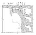
- FIG. 1is a cross-sectional view of one embodiment of the invention.
- FIG. 2is a blown-up cross-sectional view of one embodiment of the invention.
- FIG. 3is a perspective side view of one embodiment of the invention.
- FIG. 4is a cross-sectional view of one embodiment of the invention.
- the closure 10can be configured to either snap or be threaded onto the container 20 .
- the container 20preferably has a neck 22 with a base portion 24 and an upper portion 30 .
- the neck 22defines the opening 26 of the container 20 .
- the upper portion 30has a proximal segment 32 that is oriented in a first inward angle relative to the base portion 24 and a distal segment 36 that is oriented in a second inward angle relative the base portion 24 .
- the proximal segment 32has an upper surface 34 .
- the proximal segment 32is oriented at an angle that is about 5 to 60 degrees from the base portion 24 of the neck 22 .
- the distal segment 36can be oriented at an angle that is about 0.0 to 45 degrees off horizontal and preferably about 5 to 10 degrees from the base portion 24 of the neck 22 .
- the proximal segment 32when compared to the base portion 24 of the neck 22 , which is preferably substantially vertical, is oriented in a steeper slope while the distal segment 36 is oriented in a gentler slope.
- the proximal segment 32defines a slope that is about 35 degrees steeper than the slope of the distal segment 36 .
- the closure 10preferably has a generally planar top portion 18 , an outer peripheral edge portion 14 , and an annular skirt 16 depending from the peripheral edge portion 14 .
- the top portion 18is circular and has at least one inner flange 40 and at least one outer flange 50 depending therefrom.
- the outer flange 50forms a first circular ring 62 which has a first diameter.
- the outer flange 50is one continuous formation forming the first ring 62 .
- the outer flange 50is relatively flexible when compared to the inner flange 40 .
- the outer flange 50can have an angled inner surface 52 and an outer surface 54 .
- the angled inner surface 52is preferably at an angle off a vertical line about 5 to 80 degrees from the top portion.
- the angled inner surface 52is at an angle about 10 to 70 degrees from the top portion 18 . Most preferably, the angled inner surface 52 is at an angle of about 30 degrees off vertical from the top portion 18 .
- the outer surface 54is oriented substantially perpendicular to the top portion 18 .
- the outer flange 50can have a cross-sectional shape of a right triangle with the inner angled surface being the hypotenuse.
- the inner flange 40should be relatively rigid compared to the outer flange 50 and have an outer angled surface 42 . It should have a triangular cross-sectional shape.
- the inner flange 40forms a second circular ring 64 which has a second diameter that is less than the first diameter.
- the inner flange 40can be one continuous formation forming the second ring 64 , or it can be a plurality of segments that, together, effectively forms the second ring 64 .
- the outer angled surface 42 of the inner flange 40is preferably at an angle of about 60 to 85 degrees from the top portion 18 . More preferably, the outer angled surface 42 is at an angle of about 82 degrees from the top portion 18 .
- the inner flange 40can have a cross-sectional shape of an isosceles triangle.
- the inner flange 40 and outer flange 50each have a height which is the distance that they depend from the top portion 18 . In one embodiment, the inner flange 40 and outer flange 50 have the same height. In another embodiment, the inner flange 40 has a greater height than the outer flange 50 . In another embodiment, the inner flange 40 has a lesser height than the outer flange 50 .
- the inner flange 40 and outer flange 50can be oriented in concentric rings 62 , 64 on the top portion 18 .
- the inner flange 40 and outer flange 50define a channel 66 between them.
- the channel 66is capable of receiving a part 68 of the upper portion 30 of the neck 22 .
- the part 68 of the upper portion 30 of the neck 22includes the distal segment 36 and a portion of the proximal segment 32 .
- the upper portion 30 of the neck 22is flexible.
- the inner flange 40biases the part 68 of the upper portion 30 of neck 22 that is in the channel 66 against the outer flange 50 .
- the inner flange 40can act like a backstop that causes the upper portion 30 of the neck 22 to become wedged in the channel 66 .
- the surface 34 of part 68 of the upper portion 30 of the neck 22is biased against the inner surface 52 of the outer flange 50 .
- the part 68 of the upper portion 30forms a surface seal between the surface 34 of part 68 and the inner surface 52 . More preferably, at least part of an upper surface 34 of the proximal segment 32 of the neck 22 and at least part of the inner surface 52 of the outer flange 50 form a surface seal.
- the upper portion 30 of the neckwill not form a seal with the inner flange 40 .
- the term surface sealis a joining along a surface of a first object and a surface of a second object for a distance along both surfaces. As such, the surface seal defines an area. This would be in comparison to a line seal, which would be a joining of an edge of one object and the surface of a second object.
- upper surface 34may contact the inner surface 42 or the top portion 18 of the closure 10 to form a secondary seal.
- the slope of the distal segment 36 of the neck 22 and the slope of the inner surface 52 of the outer flange 50are relatively similar.
- the proximal segment 32has a slope that is about 0 to 6.0 degrees offset from the inner surface 52 of the outer flange 50 .
- the proximal segment 32has a slope that is about 1.0 to 3.0 degrees offset from the inner surface 52 .
- the neck 22 of the container 20 and the top portion 18 of the container 20move closer together.
- the angled nature of the outer flange 50 and the slope of the upper portion 30 of the neck 22guide the combination into the proper closed position.
- FIG. 4shows an embodiment of a closure 110 and container 120 combination.
- the container 120preferably has a neck 122 with a base portion 124 and an upper portion 130 .
- the neck 122defines an opening 126 of the container 120 .
- the upper portion 130has a distal segment 136 that has an outer wall 138 and an inner wall 139 .
- the outer wall 138is angled at about 5 to 60 degrees off vertical from the neck 122 . More preferably, the outer wall 138 is angled at about 30 degrees off vertical.
- the closure 110preferably has a generally planar top portion 118 , an outer peripheral edge portion 114 , and an annular skirt 116 depending from the peripheral edge portion 114 .
- the top portion 118is circular and has at least one inner flange 140 and at least one outer flange 150 depending therefrom.
- the outer flange 150is relatively flexible when compared to the inner flange 140 .
- the outer flange 150can have an angled inner surface 152 and an outer surface 154 .
- the angled inner surface 152is preferably at an angle about 5 to 80 degrees off vertical from the top portion 118 . More preferably, the angled inner surface 152 is at an angle about 10 to 70 degrees from the top portion 118 .
- the angled inner surface 152is at an angle of about 30 degrees off vertical from the top portion 118 .
- the outer surface 154is oriented substantially perpendicular to the top portion 118 .
- the outer flange 150can have a cross-sectional shape of a right triangle with the inner angled surface being the hypotenuse.
- the inner flange 140can be relatively rigid compared to the outer flange 150 and have an outer angled surface 142 .
- the inner flange 140can have a triangular cross-sectional shape.
- the outer angled surface 142 of the inner flange 40is preferably at an angle of about 40 to 85 degrees from the top portion 118 . More preferably, the outer angled surface 142 is at an angle of about 60 degrees from the top portion 118 .
- the inner flange 140can have a cross-sectional shape of an isosceles triangle.
- the inner flange 140 and outer flange 150each have a height which is the distance that they depend from the top portion 118 . In one embodiment, the inner flange 140 and outer flange 150 have the same height. In another embodiment, the inner flange 140 has a greater height than the outer flange 150 . In another embodiment, the inner flange 140 has a lesser height than the outer flange 150 .
- the inner flange 140 and outer flange 150define a channel 166 between them.
- the channel 166is capable of receiving a part of the distal segment 136 of the neck 122 .
- the distal segment 136can be composed of PET and be relatively inflexible.
- the inner flange 140biases the distal segment 136 that is in the channel 166 against the outer flange 150 .
- the inner flange 140can act like a backstop that causes part of the distal segment 136 of the 122 to become wedged in the channel 166 .
- the distal segment 136is biased against the inner surface 152 of the outer flange 150 .
- the outer wall 138 of the distal segment 136forms a surface seal with the inner surface 152 of the outer flange 150 .
- the inner surface 152has a slope that is about 0 to 6.0 degrees offset from the slope of the outer wall 138 . More preferably, the inner surface 152 has a slope that is about 1.0 to 3.0 degrees offset from the slope of the outer wall 138 .
- the inner wall 139 of the distal segment 136 of the neck 122may form a surface seal with the inner flange 140 .
- the closure 10can be comprised of a variety of different materials that are known in the art.
- the closure 10can be comprised of plastic including the specific plastic PET.
- the container 20can be comprised of a variety of different materials, including plastic.
Landscapes
- Engineering & Computer Science (AREA)
- Mechanical Engineering (AREA)
- Closures For Containers (AREA)
Abstract
Description
Claims (13)
Priority Applications (1)
| Application Number | Priority Date | Filing Date | Title |
|---|---|---|---|
| US11/652,789US8056744B2 (en) | 2007-01-12 | 2007-01-12 | Closure with ring ribs |
Applications Claiming Priority (1)
| Application Number | Priority Date | Filing Date | Title |
|---|---|---|---|
| US11/652,789US8056744B2 (en) | 2007-01-12 | 2007-01-12 | Closure with ring ribs |
Publications (2)
| Publication Number | Publication Date |
|---|---|
| US20080169262A1 US20080169262A1 (en) | 2008-07-17 |
| US8056744B2true US8056744B2 (en) | 2011-11-15 |
Family
ID=39616963
Family Applications (1)
| Application Number | Title | Priority Date | Filing Date |
|---|---|---|---|
| US11/652,789Active2029-07-25US8056744B2 (en) | 2007-01-12 | 2007-01-12 | Closure with ring ribs |
Country Status (1)
| Country | Link |
|---|---|
| US (1) | US8056744B2 (en) |
Cited By (1)
| Publication number | Priority date | Publication date | Assignee | Title |
|---|---|---|---|---|
| US10287039B2 (en)* | 2014-07-19 | 2019-05-14 | William M. Heyn | Induction heat sealed container closures |
Families Citing this family (11)
| Publication number | Priority date | Publication date | Assignee | Title |
|---|---|---|---|---|
| JP3142618U (en)* | 2008-04-08 | 2008-06-19 | ロート製薬株式会社 | Container for liquid |
| FR2942777B1 (en)* | 2009-03-06 | 2016-02-05 | Sartorius Stedim Biotech Sa | SELF-TIGHTENING SKIRT MOUNTING FOR THE FITTING OF, OR CONNECTION TO, AN ANNULAR, QUICK-SETTING AND REMOVAL COLLAR, INTENDED FOR BIOPHARMACEUTICALS |
| US10100273B2 (en)* | 2010-11-22 | 2018-10-16 | Corning Incorporated | Closure assembly for cell culture apparatus |
| US8424695B2 (en) | 2011-06-22 | 2013-04-23 | Van Blarcom Closures, Inc. | Spring action child resistant closure and container |
| US9254941B2 (en)* | 2014-03-25 | 2016-02-09 | Basf Corporation | Resealable container and closure package |
| JP6548440B2 (en)* | 2015-04-15 | 2019-07-24 | 東京ライト工業株式会社 | Container and cap |
| KR101707731B1 (en)* | 2015-04-20 | 2017-02-17 | 정규열 | Mascara applicator wich air tight of wedge combination means |
| KR102701926B1 (en)* | 2017-08-10 | 2024-09-02 | 도판 홀딩스 가부시키가이샤 | Packaging container having a spout stopper and a spout stopper |
| USD872528S1 (en)* | 2018-04-09 | 2020-01-14 | Tien-Chang Hsu | Spout of travel mug |
| US20220097935A1 (en)* | 2020-09-28 | 2022-03-31 | Closure Systems International Inc. | Package and closure with tamper-evident band |
| US20240308734A1 (en)* | 2023-03-15 | 2024-09-19 | Kw Container | Storage device incorporating a liquid-tight sealing system |
Citations (32)
| Publication number | Priority date | Publication date | Assignee | Title |
|---|---|---|---|---|
| US3463340A (en) | 1966-09-28 | 1969-08-26 | Alrik Civer Lindstrom | Screw cap with locking means |
| US3844439A (en) | 1972-07-28 | 1974-10-29 | Consumers Glass Co Ltd | Linerless closures |
| US4143785A (en) | 1978-03-16 | 1979-03-13 | Sun Coast Plastic Closures, Inc. | Plastic vacuum sealing cap |
| US4276989A (en) | 1978-11-06 | 1981-07-07 | Hicks David M | Closures |
| US4531649A (en) | 1984-04-23 | 1985-07-30 | Anchor Hocking Corporation | Molded plastic cap with sealing liner |
| US4560077A (en) | 1984-09-25 | 1985-12-24 | Sun Coast Plastics, Inc. | Plastic closure cap |
| US4561553A (en) | 1985-01-22 | 1985-12-31 | Northern Engineering And Plastics Corp. | Snap on twist off tamper-proof closure for containers |
| US4566603A (en) | 1984-07-12 | 1986-01-28 | Phoenix Closures, Inc. | Linerless closure |
| US4609115A (en) | 1985-05-15 | 1986-09-02 | Phoenix Closures, Inc. | Tamper-evident closure and bottle assembly |
| US4637519A (en) | 1985-09-03 | 1987-01-20 | Sun Coast Plastics, Inc. | Two part closure |
| US4844268A (en) | 1987-09-25 | 1989-07-04 | Cap Snap Co. | Tamper-evident cap and neck structure |
| US4913299A (en) | 1989-04-03 | 1990-04-03 | Phoenix Closures, Inc. | Back-off resistant closure for a container |
| US5213224A (en) | 1990-08-09 | 1993-05-25 | Portola Packaging, Inc. | Snap-on, screw-off cap and container neck |
| US5292020A (en) | 1993-05-13 | 1994-03-08 | Phoenix Closures, Inc. | Closure with anti-backoff feature |
| US5449078A (en) | 1994-07-08 | 1995-09-12 | Thermar Corporation | Combination of a container and a safety cap therefor |
| US5489036A (en) | 1994-11-30 | 1996-02-06 | Kraft Foods, Inc. | Screw threaded container with a triple seal |
| US5553727A (en) | 1995-04-27 | 1996-09-10 | Consumer Cap Corporation | Tamper-evident cap and neck finish |
| US5560504A (en) | 1993-03-24 | 1996-10-01 | Molinaro; Luca | Snap on pull off tamper indicating flexible cap and neck configuration |
| US5887738A (en) | 1990-08-09 | 1999-03-30 | Portola Packaging, Inc. | Foil lined snap-on, screw-off closure and container neck |
| US5927532A (en) | 1997-04-21 | 1999-07-27 | Owens-Illinois Closure Inc. | Vapor-seal child resistant closure and container package |
| US5971183A (en) | 1995-12-15 | 1999-10-26 | The Procter & Gamble Company | Tamper-evident leak-tight closure for containers |
| US6003701A (en) | 1998-02-04 | 1999-12-21 | Hidding; Walter E. | Tamper resistant bottle cap and neck |
| US6044994A (en) | 1998-08-03 | 2000-04-04 | Phoenix Closures, Inc. | Sealing arrangement for closure caps having liners |
| US6082569A (en) | 1988-06-17 | 2000-07-04 | Closures And Packaging Services Limited | Linerless closure for carbonated beverage container |
| US6164503A (en) | 1999-01-15 | 2000-12-26 | Weatherchem Corporation | Closure for liquids |
| US6257432B1 (en) | 1999-12-29 | 2001-07-10 | Phoenix Closures, Inc. | Cap and container assembly |
| US20030155323A1 (en)* | 2002-02-15 | 2003-08-21 | Leonard Ekkert | Apparatus and method allowing gas flowing into and/or out of container |
| US20040188375A1 (en)* | 2002-07-03 | 2004-09-30 | Fabricas Monterrey, S.A. De C.V. | Linerless plastic closure with a sealing lip |
| US6848590B2 (en) | 2001-10-16 | 2005-02-01 | Owens-Illinois Closure Inc. | Child-resistant closure and container package |
| US6874648B2 (en) | 2001-09-21 | 2005-04-05 | Owens-Illinois Closure Inc. | Closure with gas-barrier liner and package incorporating same |
| US20050103742A1 (en) | 2002-01-16 | 2005-05-19 | Dimitros Pairis | Plastic closing cap with sealing ring |
| US20060108316A1 (en)* | 2000-11-21 | 2006-05-25 | King Roger M | Plug seals for user-friendly cap assemblies |
- 2007
- 2007-01-12USUS11/652,789patent/US8056744B2/enactiveActive
Patent Citations (33)
| Publication number | Priority date | Publication date | Assignee | Title |
|---|---|---|---|---|
| US3463340A (en) | 1966-09-28 | 1969-08-26 | Alrik Civer Lindstrom | Screw cap with locking means |
| US3844439A (en) | 1972-07-28 | 1974-10-29 | Consumers Glass Co Ltd | Linerless closures |
| US4143785A (en) | 1978-03-16 | 1979-03-13 | Sun Coast Plastic Closures, Inc. | Plastic vacuum sealing cap |
| US4276989A (en) | 1978-11-06 | 1981-07-07 | Hicks David M | Closures |
| US4531649A (en) | 1984-04-23 | 1985-07-30 | Anchor Hocking Corporation | Molded plastic cap with sealing liner |
| US4566603A (en) | 1984-07-12 | 1986-01-28 | Phoenix Closures, Inc. | Linerless closure |
| US4560077A (en) | 1984-09-25 | 1985-12-24 | Sun Coast Plastics, Inc. | Plastic closure cap |
| US4561553A (en) | 1985-01-22 | 1985-12-31 | Northern Engineering And Plastics Corp. | Snap on twist off tamper-proof closure for containers |
| US4609115A (en) | 1985-05-15 | 1986-09-02 | Phoenix Closures, Inc. | Tamper-evident closure and bottle assembly |
| US4637519A (en) | 1985-09-03 | 1987-01-20 | Sun Coast Plastics, Inc. | Two part closure |
| US4844268A (en) | 1987-09-25 | 1989-07-04 | Cap Snap Co. | Tamper-evident cap and neck structure |
| US6082569A (en) | 1988-06-17 | 2000-07-04 | Closures And Packaging Services Limited | Linerless closure for carbonated beverage container |
| US4913299A (en) | 1989-04-03 | 1990-04-03 | Phoenix Closures, Inc. | Back-off resistant closure for a container |
| US5213224A (en) | 1990-08-09 | 1993-05-25 | Portola Packaging, Inc. | Snap-on, screw-off cap and container neck |
| US5887738A (en) | 1990-08-09 | 1999-03-30 | Portola Packaging, Inc. | Foil lined snap-on, screw-off closure and container neck |
| US5560504A (en) | 1993-03-24 | 1996-10-01 | Molinaro; Luca | Snap on pull off tamper indicating flexible cap and neck configuration |
| US5292020A (en) | 1993-05-13 | 1994-03-08 | Phoenix Closures, Inc. | Closure with anti-backoff feature |
| US5449078A (en) | 1994-07-08 | 1995-09-12 | Thermar Corporation | Combination of a container and a safety cap therefor |
| US5489036A (en) | 1994-11-30 | 1996-02-06 | Kraft Foods, Inc. | Screw threaded container with a triple seal |
| US5553727A (en) | 1995-04-27 | 1996-09-10 | Consumer Cap Corporation | Tamper-evident cap and neck finish |
| US5553727C1 (en) | 1995-04-27 | 2001-09-04 | Rical Sa | Tamper-evident cap and neck finish |
| US5971183A (en) | 1995-12-15 | 1999-10-26 | The Procter & Gamble Company | Tamper-evident leak-tight closure for containers |
| US5927532A (en) | 1997-04-21 | 1999-07-27 | Owens-Illinois Closure Inc. | Vapor-seal child resistant closure and container package |
| US6003701A (en) | 1998-02-04 | 1999-12-21 | Hidding; Walter E. | Tamper resistant bottle cap and neck |
| US6044994A (en) | 1998-08-03 | 2000-04-04 | Phoenix Closures, Inc. | Sealing arrangement for closure caps having liners |
| US6164503A (en) | 1999-01-15 | 2000-12-26 | Weatherchem Corporation | Closure for liquids |
| US6257432B1 (en) | 1999-12-29 | 2001-07-10 | Phoenix Closures, Inc. | Cap and container assembly |
| US20060108316A1 (en)* | 2000-11-21 | 2006-05-25 | King Roger M | Plug seals for user-friendly cap assemblies |
| US6874648B2 (en) | 2001-09-21 | 2005-04-05 | Owens-Illinois Closure Inc. | Closure with gas-barrier liner and package incorporating same |
| US6848590B2 (en) | 2001-10-16 | 2005-02-01 | Owens-Illinois Closure Inc. | Child-resistant closure and container package |
| US20050103742A1 (en) | 2002-01-16 | 2005-05-19 | Dimitros Pairis | Plastic closing cap with sealing ring |
| US20030155323A1 (en)* | 2002-02-15 | 2003-08-21 | Leonard Ekkert | Apparatus and method allowing gas flowing into and/or out of container |
| US20040188375A1 (en)* | 2002-07-03 | 2004-09-30 | Fabricas Monterrey, S.A. De C.V. | Linerless plastic closure with a sealing lip |
Cited By (1)
| Publication number | Priority date | Publication date | Assignee | Title |
|---|---|---|---|---|
| US10287039B2 (en)* | 2014-07-19 | 2019-05-14 | William M. Heyn | Induction heat sealed container closures |
Also Published As
| Publication number | Publication date |
|---|---|
| US20080169262A1 (en) | 2008-07-17 |
Similar Documents
| Publication | Publication Date | Title |
|---|---|---|
| US8056744B2 (en) | Closure with ring ribs | |
| US20200331672A1 (en) | Container and lid with audible and tactile feedback | |
| US10293988B2 (en) | Fitment and overcap therefor | |
| US5377861A (en) | Container closure with external ribs | |
| US6170691B1 (en) | Open-head container and lid assembly | |
| US8066158B2 (en) | Closure for a container | |
| JP2576052Y2 (en) | Leak-resistant screw cap with improved gas impermeability | |
| CA2333473C (en) | Barrel with plastic lid | |
| US4742935A (en) | Packaging container | |
| AU2010294420B2 (en) | Package with foil seals and penetrating means | |
| US5161707A (en) | Closure with linerless seal | |
| US9156597B2 (en) | Child resistant, tamper evident container | |
| CN101296849B (en) | Dispensing cap for liquid container | |
| US8403174B2 (en) | Snap resealing closure for a container | |
| US20080073382A1 (en) | Closure and container neck | |
| RU2679548C2 (en) | Airtight container for pressurized beverage and method for manufacture thereof | |
| US20140238988A1 (en) | Sealing overcap for a container | |
| JP2009535269A (en) | Container closure having means for introducing additives into the contents of the container | |
| US20180022594A1 (en) | Container for receiving and storing fluid | |
| ES2539279T3 (en) | Closure system | |
| US20140158687A1 (en) | Moisture Retention Seal | |
| RU2346866C2 (en) | Containers for drinks | |
| CN105377712A (en) | Hygienic seals for containers | |
| US5680946A (en) | Sealable container | |
| JP6240690B2 (en) | Sealed container |
Legal Events
| Date | Code | Title | Description |
|---|---|---|---|
| AS | Assignment | Owner name:PHOENIX CLOSURES, INC., ILLINOIS Free format text:ASSIGNMENT OF ASSIGNORS INTEREST;ASSIGNOR:EKKERT, LEN;REEL/FRAME:018950/0644 Effective date:20070112 | |
| STCF | Information on status: patent grant | Free format text:PATENTED CASE | |
| FPAY | Fee payment | Year of fee payment:4 | |
| AS | Assignment | Owner name:FIFTH THIRD BANK, AN OHIO BANKING CORPORATION, ILL Free format text:SECURITY INTEREST;ASSIGNOR:PHOENIX CLOSURES, INC., AN ILLINOIS CORPORATION;REEL/FRAME:043153/0871 Effective date:20170801 | |
| FEPP | Fee payment procedure | Free format text:MAINTENANCE FEE REMINDER MAILED (ORIGINAL EVENT CODE: REM.); ENTITY STATUS OF PATENT OWNER: SMALL ENTITY | |
| FEPP | Fee payment procedure | Free format text:7.5 YR SURCHARGE - LATE PMT W/IN 6 MO, SMALL ENTITY (ORIGINAL EVENT CODE: M2555); ENTITY STATUS OF PATENT OWNER: SMALL ENTITY | |
| MAFP | Maintenance fee payment | Free format text:PAYMENT OF MAINTENANCE FEE, 8TH YR, SMALL ENTITY (ORIGINAL EVENT CODE: M2552); ENTITY STATUS OF PATENT OWNER: SMALL ENTITY Year of fee payment:8 | |
| MAFP | Maintenance fee payment | Free format text:PAYMENT OF MAINTENANCE FEE, 12TH YR, SMALL ENTITY (ORIGINAL EVENT CODE: M2553); ENTITY STATUS OF PATENT OWNER: SMALL ENTITY Year of fee payment:12 |