US8055753B2 - Peer to peer job monitoring and control in grid computing systems - Google Patents
Peer to peer job monitoring and control in grid computing systemsDownload PDFInfo
- Publication number
- US8055753B2 US8055753B2US10/458,956US45895603AUS8055753B2US 8055753 B2US8055753 B2US 8055753B2US 45895603 AUS45895603 AUS 45895603AUS 8055753 B2US8055753 B2US 8055753B2
- Authority
- US
- United States
- Prior art keywords
- computer
- processing
- submitter
- user interface
- client
- Prior art date
- Legal status (The legal status is an assumption and is not a legal conclusion. Google has not performed a legal analysis and makes no representation as to the accuracy of the status listed.)
- Active, expires
Links
- 238000012544monitoring processMethods0.000titleclaimsabstractdescription21
- 238000000034methodMethods0.000claimsabstractdescription139
- 230000008569processEffects0.000claimsabstractdescription133
- 238000012545processingMethods0.000claimsabstractdescription110
- 230000006854communicationEffects0.000claimsabstractdescription97
- 238000004891communicationMethods0.000claimsabstractdescription75
- 230000000977initiatory effectEffects0.000claimsabstractdescription3
- 230000004044responseEffects0.000claimsdescription20
- 230000008859changeEffects0.000claimsdescription2
- 230000002457bidirectional effectEffects0.000claims1
- 230000026676system processEffects0.000abstract1
- 230000006870functionEffects0.000description8
- 230000004048modificationEffects0.000description6
- 238000012986modificationMethods0.000description6
- 230000009471actionEffects0.000description2
- 238000010923batch productionMethods0.000description2
- 230000008901benefitEffects0.000description2
- 230000000694effectsEffects0.000description2
- 230000006872improvementEffects0.000description2
- 230000003993interactionEffects0.000description2
- 230000007175bidirectional communicationEffects0.000description1
- 238000001514detection methodMethods0.000description1
- 238000009826distributionMethods0.000description1
- 230000007246mechanismEffects0.000description1
- 238000003825pressingMethods0.000description1
- 238000003860storageMethods0.000description1
Images


Classifications
- F—MECHANICAL ENGINEERING; LIGHTING; HEATING; WEAPONS; BLASTING
- F16—ENGINEERING ELEMENTS AND UNITS; GENERAL MEASURES FOR PRODUCING AND MAINTAINING EFFECTIVE FUNCTIONING OF MACHINES OR INSTALLATIONS; THERMAL INSULATION IN GENERAL
- F16L—PIPES; JOINTS OR FITTINGS FOR PIPES; SUPPORTS FOR PIPES, CABLES OR PROTECTIVE TUBING; MEANS FOR THERMAL INSULATION IN GENERAL
- F16L47/00—Connecting arrangements or other fittings specially adapted to be made of plastics or to be used with pipes made of plastics
- F16L47/20—Connecting arrangements or other fittings specially adapted to be made of plastics or to be used with pipes made of plastics based principally on specific properties of plastics
- F16L47/22—Connecting arrangements or other fittings specially adapted to be made of plastics or to be used with pipes made of plastics based principally on specific properties of plastics using shrink-down material
- H—ELECTRICITY
- H04—ELECTRIC COMMUNICATION TECHNIQUE
- H04L—TRANSMISSION OF DIGITAL INFORMATION, e.g. TELEGRAPHIC COMMUNICATION
- H04L67/00—Network arrangements or protocols for supporting network services or applications
- H04L67/01—Protocols
- H04L67/10—Protocols in which an application is distributed across nodes in the network
- F—MECHANICAL ENGINEERING; LIGHTING; HEATING; WEAPONS; BLASTING
- F16—ENGINEERING ELEMENTS AND UNITS; GENERAL MEASURES FOR PRODUCING AND MAINTAINING EFFECTIVE FUNCTIONING OF MACHINES OR INSTALLATIONS; THERMAL INSULATION IN GENERAL
- F16L—PIPES; JOINTS OR FITTINGS FOR PIPES; SUPPORTS FOR PIPES, CABLES OR PROTECTIVE TUBING; MEANS FOR THERMAL INSULATION IN GENERAL
- F16L47/00—Connecting arrangements or other fittings specially adapted to be made of plastics or to be used with pipes made of plastics
- F16L47/06—Connecting arrangements or other fittings specially adapted to be made of plastics or to be used with pipes made of plastics with sleeve or socket formed by or in the pipe end
- F16L47/12—Connecting arrangements or other fittings specially adapted to be made of plastics or to be used with pipes made of plastics with sleeve or socket formed by or in the pipe end with additional locking means
- F—MECHANICAL ENGINEERING; LIGHTING; HEATING; WEAPONS; BLASTING
- F16—ENGINEERING ELEMENTS AND UNITS; GENERAL MEASURES FOR PRODUCING AND MAINTAINING EFFECTIVE FUNCTIONING OF MACHINES OR INSTALLATIONS; THERMAL INSULATION IN GENERAL
- F16L—PIPES; JOINTS OR FITTINGS FOR PIPES; SUPPORTS FOR PIPES, CABLES OR PROTECTIVE TUBING; MEANS FOR THERMAL INSULATION IN GENERAL
- F16L47/00—Connecting arrangements or other fittings specially adapted to be made of plastics or to be used with pipes made of plastics
- F16L47/20—Connecting arrangements or other fittings specially adapted to be made of plastics or to be used with pipes made of plastics based principally on specific properties of plastics
- F16L47/24—Connecting arrangements or other fittings specially adapted to be made of plastics or to be used with pipes made of plastics based principally on specific properties of plastics for joints between metal and plastics pipes
- F—MECHANICAL ENGINEERING; LIGHTING; HEATING; WEAPONS; BLASTING
- F16—ENGINEERING ELEMENTS AND UNITS; GENERAL MEASURES FOR PRODUCING AND MAINTAINING EFFECTIVE FUNCTIONING OF MACHINES OR INSTALLATIONS; THERMAL INSULATION IN GENERAL
- F16L—PIPES; JOINTS OR FITTINGS FOR PIPES; SUPPORTS FOR PIPES, CABLES OR PROTECTIVE TUBING; MEANS FOR THERMAL INSULATION IN GENERAL
- F16L58/00—Protection of pipes or pipe fittings against corrosion or incrustation
- F16L58/02—Protection of pipes or pipe fittings against corrosion or incrustation by means of internal or external coatings
- F16L58/04—Coatings characterised by the materials used
- F16L58/10—Coatings characterised by the materials used by rubber or plastics
Definitions
- This inventionrelates to the fields of parallel processing, batch processing, and grid computing, and particularly to applications where the submitter of batch jobs needs to interact with batch jobs during their execution.
- the disclosed implementationprovides for improved communication and feedback between the originator of jobs and the client systems processing those jobs, such that the submitter is able to receive real time feedback on job progress, and to send real-time commands to alter the continued operation of said jobs.
- the inventionparticularly is directed to applications where the submitter of batch jobs needs to interact with batch jobs during their execution.
- IBM®is a registered trademark of International Business Machines Corporation, Armonk, N.Y., U.S.A. Other names may be registered trademarks or product names of International Business Machines Corporation or other companies.
- Batch processing and parallel processing systemshave existed for many years. These typically can be used to submit single jobs for processing, for multiple independent jobs, or for a set of related jobs that may comprise sub-steps of a larger job.
- IBM's LoadLeveleris an example of such a system
- Grid Computingis a new field that builds on what was provided with LoadLeveler, extending it with flexibility and security for use in more diverse environments.
- a typical implementation of a parallel processing systemallows multiple clients to each submit multiple job steps to be distributed among a pool of clients for processing. This is typically accomplished by having a centralized server receive all such requests, and prioritize and distribute them to a pool of client systems for processing.
- the centralized serveris responsible for workload balancing among the clients, and for the commands to the client systems necessary to start and maintain jobs, and for monitoring activity and notifying the submitter of status, such as completion of the job steps on each client.
- a centralized server as previously used for dispatch and management of batch jobsremains unmodified, as in prior art.
- this invention's preferred embodimentprovides for improved communication and feedback between the originator of jobs and the client systems processing those jobs, such that the submitter is able to receive real time feedback on job progress, and to send real-time commands to alter the continued operation of said jobs.
- the submitter application of batch jobs applicationsallows interacting with batch jobs during their execution.
- software layersare added at each submitter's system and at each batch client where a job step is processed. These additional software layers utilize pipelines and communication protocols (such as TCP/IP sockets) to enable direct communication between the submitter's system and each job step on the respective processing client.
- Additional software layersare under control of the job submitter application, and may be modified if necessary to support specific requirements of the submitter's workload, with no modification to the centralized batch manager.
- These additional software layersutilize peer to peer communication between the submitter's system and each batch processing client, permitting communication directly between the submitter's client system and each processing client, without use of a communications channel through the centralized batch manager.
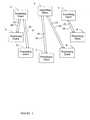
- FIG. 1illustrates connections between a centralized server and submitting systems and processing systems, both of which may be considered clients of the centralized server.
- FIG. 2illustrates direct peer to peer connections between submitting and processing clients.
- FIG. 3illustrates the software layers (independent process threads) added on the submitting and processing clients to enable direct communication.
- FIG. 4illustrates an unmodified job control file for submitting a multi-step job.
- FIG. 5illustrates a job control file modified to insert invocation of additional communication processes for each step of a multi-step job.
- FIG. 6illustrates a typical main user interface window.
- FIG. 7illustrates a user interface sub-window for displaying more detail of the progress of one individual job step.
- FIG. 8illustrates an alert window to notify the submitter immediately of a failed job step.
- FIG. 9illustrates an alert window to notify the submitter of the completion of all job steps, and to provide a concise summary of the results.
- FIG. 1illustrates a typical system for distributing a workload from a plurality of submitters to a multitude of clients for processing.
- a centralized server 1to which all requests are made, and from which all clients receive requests for processing.
- Clientsare often capable of being submitters or processors, and may switch from one role to the other, or even act as both submitters and processors at the same time.
- clients 2 , 3 , and 4will function as submitters, and clients 5 , 6 , 7 , 8 , and 9 will provide processing services.
- the communications structure shown, consisting of links 10 , 11 , 12 , 13 , 14 , 15 , 16 , and 17are used by the clients for communication with the centralized server 1 .
- These communication linksare utilized by the submitters 2 , 3 , and 4 to make requests for processing services, and for the centralized server 1 to dispatch processing requests to clients 5 , 6 , 7 , 8 , and 9 , and for the centralized server to monitor the status and progress of all the clients.
- Centralized server 1may also provide some feedback to submitting clients 2 , 3 , and 4 , for example notification of completion of processing and the return of final results, if not returned via another mechanism, such as a shared file storage system.
- This communications structureremains unchanged for the present invention, and continues to fulfill these roles, and centralized server 1 continues to fill the important role of workload balancing among the clients.
- FIG. 2illustrates additional communication paths opened by the subject invention for communication between clients (these communication paths are in addition to the paths in FIG. 1 , but are shown separately for clarity). These communication paths are established by the clients, with no participation by the centralized server 1 shown in FIG. 1 .
- client 2has made a request for processing services, and that this request has been assigned by server 1 to be performed on clients 5 and 6 .
- client 3has made a request for processing services, and that this request has been assigned by server 1 to be performed on clients 7 and 8 .
- client 4has made a request for processing services, and that this request has been assigned by server 1 to be performed on client 9 .
- Communication paths 18 and 19will be opened between clients 2 and 5 , as shown.
- Communication paths 20 and 21will be opened between clients 2 and 6 , as shown.
- communication paths 22 , 23 , 24 , 25 , 26 , and 27will be opened between the remaining submitting clients and processing clients, as shown, corresponding to the job step distribution described previously.
- FIG. 3illustrates the communications between submitting client 2 , located in the upper portion of the figure, and processing clients 5 and 6 , located in the lower portion of the figure, in greater detail.
- This figureshows the individual software process threads that together provide the communication services that are the subject of this invention.
- a requestis submitted by client 2 to the batch server 1 .
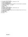
- This requestmay be in the form of a control file, such as shown in FIG. 4 .
- This control fileis typical of prior art systems.
- This example control filespecifies a 2 step job requiring 2 processing clients, but any number of job steps may be specified. Two clients would ordinarily be expected to process the 2 example steps in parallel (simultaneously).
- Lines 1 through 11are the control information and parameters for the first job step
- lines 12 through 22are the control information and parameters for the second job step.
- the request by client 2 to batch server 1must be modified to cause the processing clients to start a monitoring process ahead of the actual batch job step.
- Thisis accomplished by modifying the control file of FIG. 4 as shown in FIG. 5 .
- This fileis modified at lines 6 and 17 for the two job steps, with the modifications highlighted for illustration purposes in a boldface font.
- the arguments specified in these lines of the control filespecify the jobs to be run on the processing clients 5 and 6 , respectively.
- Client 5is instructed by this change to run monitoring process “llsim”, with the remainder of this line containing the arguments to this program.
- These argumentsinclude:
- An optional secret security key 49 used by processing clients to authenticate their access to the submitter's system for acceptanceshown as key0 in the example. This may be generated by various methods, including randomly, with each new job submission using a different key. This key, passed by centralized host 1 to processing clients 5 and 6 , is used for access back to the submitting client 2 . This insures that submitting client 2 accepts input from only those jobs that it launched.
- the submitterinvokes a program that will prepare to accept communications from the processing clients (these will be clients 5 and 6 in this example, but the identity of these clients is not yet known to the submitter), and that will submit the modified job requests to centralized server 1 for processing.
- the submitterinvokes program “llsim”, supplying as an argument the name of the control file shown in FIG. 4 .
- Program “llsim”the same program that will be the monitoring process on processing clients, is able to determine whether it is running on a submitter's system (client 2 in this example) or a processing client (client 5 or 6 in this example), and take actions appropriate to its run environment. It determines this by examining the arguments supplied to the program. Alternate implementations could use different programs on the submitter's system and the processing clients.
- the monitoring program “llsim”executes the following steps, and starts processes shown in FIG. 3 :
- the programprepares a table to hold the process ID of all child processes that it will create, so that it can terminate all said processes when the main process is terminated, and avoid leaving any zombie processes running. Each child process will be entered into the table as it is created in the following steps.
- the programalso hooks into “kill”, “quit”, and similar events to terminate the processes in this table whenever the main program is ended.
- the programforks a child process 29 , and the parent exits.
- the childtakes over as the new main process (this step is optional, but on some operating systems this makes the process a background process, and returns the user to a command prompt).
- the newly created process 29will handle all interactions with the user.
- User interface process 29searches for a free communications port, and opens the selected port to listen for a connection from connection sub process 30 and communication sub processes 31 , 32 , and any additional communication sub processes that may be created.
- the port openedis 39 on the user interface process 29 in FIG. 3 . If the preferred port is in use (possible if another instance of the program is already running) another port is chosen, and the background color of user interface windows will be changed to distinguish this instance from other instances.
- User interface process 29then forks a child process 30 for accepting connections from batch machines, and each continues with its own execution path. These two processes (independent process threads) establish a connection between themselves on communications link 39 , possibly requiring use of a secret key generated before the sub processes are created, and shared with each new sub process as part of the fork process, for communications to be accepted.
- user interface process 29prepares to communicate with the user to receive commands and display results.
- this interfaceconsists of a graphical user interface, but other methods might also be utilized. This process is able to receive both user input from the graphical interface, and data from TCP/IP connections from other processes also running on the submitter's system.
- the graphical user interfaceis exited, all sub processes on client 2 will be killed, and the monitoring process will be complete on the submitter's system 2 . This may take place before or after all processing steps have completed on processing clients 5 and 6 . If terminated early, no provision is made for reestablishing connection to the processing clients.
- Connection process 30opens another communications port for receiving connections from batch clients. This will be a separate port number, distinct from that created by user interface process 29 , and will be used to receive new connections from processing clients. This port is shown at the bottom of connection process 30 in FIG. 3 (there is only one port, the two connections shown both connect to the same port).
- Connection process 30now reads the batch control file shown in FIG. 4 , modifies it as shown in FIG. 5 , and submits it to centralized server 1 for processing.
- the modificationsinclude inserting the name of the monitoring process (the program's own name, “llsim”), the host name that it is running on (client2.com in this example), the communications port number opened in the previous step, and might also include a secret key or similar security device that processing clients must present to gain access to return results to the user interface process.
- Connection process 30sends selected information about the jobs just submitted back to user interface process 29 .
- the user interface processuses this information to display the number of processing steps started, and to enable a cancel command to be sent to centralized server 1 for the job name returned when the command file was submitted, should the user want to cancel processing via the centralized server.
- Centralized server 1selects processing clients, and dispatches the processing steps to the selected clients 5 and 6 .
- Connection process 30waits for a new connection from a processing client. Each time a new connection is received, connection process 30 forks another child process to handle the new connection.
- centralized server 1On each processing client, for example 5 , centralized server 1 initiates the program specified in the control file, in this case monitoring process “llsim”, which starts as process 34 in FIG. 3 .
- This processfirst determines that it is running on a processing client by examination of the arguments it receives, and follows the appropriate execution path. The first step taken is the opening of a communications port over which to communicate with submitting client 2 .
- This connectionis made to the host name and port number previously added to line 6 or 17 in FIG. 5 and supplied as program arguments to monitoring process “llsim” when processing client 5 is started by centralized server 1 .
- the initial connectionis made from response process 34 to connection process 30 over communication link 18 .
- connection process 30may require this secret key to be sent to validate the connection. Additional steps to make the connection secure may also optionally be undertaken, such as establishment of encryption of the link.
- connection process 30causes a fork, resulting in the creation of communication process 31 .
- the next connectionresults in the creation of communication process 32 , and if there are additional processing steps, additional similar communication process for each.
- Connection process 30exists only to accept new connections and start these new communication processes.
- a unique identity(the newly created process ID in the preferred embodiment) is sent back by connection process 30 to user interface process 29 over communication link 39 . This identity will be used in each future communication from communication process 31 , 32 , etc. to identify which processing client messages originate from, so they can be attributed to the correct processing client.
- connection process 30With the fork in connection process 30 , communication from response process 34 follows to the child process (communication process), and all future communications from the processing client 5 will be received by communication process 31 . Communications link 18 will remain open and connected between response process 34 and communication process 31 until the batch job step 35 on processing client 5 completes.
- response process 34sends an initial self-identifying message to communication process 31 , which will be forwarded and displayed to the user as an initial contact message.
- communication process 31receives this message, it forwards it over communications link 44 (a copy of link 39 that it inherited when it was forked from connection process 30 —links shown as 39 , 44 , and 45 connect to the same receive port within user interface process 29 ). So that user interface 29 can determine which client this message is from, communication process 31 attaches its identity (the process ID in the preferred embodiment) to the message, and may also be required to include a secret key inherited from process 30 if established by processes 29 and 30 . All future messages forwarded to user interface 29 by communications process 31 will also be tagged with this same identity.
- User interface process 29displays the received message, attributed to a particular processing client step as identified by this identity.
- Communication process 31then sends information to necessary to identify itself and its user interface process to response process 34 . These may include submitting client 2 's identification such as its host name, or secret keys, that will be used later to validate commands from user interface 29 before they are accepted and processed by command process 33 . This information is used to prevent the processing client 5 from accepting commands from any client other than the original submitter. Response process 34 saves this information to be passed to command process 33 when it is created.
- Communication process 31forwards any messages received from response process 34 to the user interface process 29 . If the communication link is closed from the processing client end, communication process 31 reports this back to user interface process 29 , which uses this information to inform the user that the processing step has completed. This detection of the communication link dropping allows the user to be informed that the processing step has completed, even if no message to this effect is received from the processing client (this may be a useful indication if the job on the processing client fails).
- Response process 34uses its remaining arguments (after removing the information that was added by connection process 30 and shown in FIG. 5 before submission to the centralized server 1 ) to start the job that was originally specified as the processing step in FIG. 4 . The procedure for starting the job is described in the next steps.
- Response process 34starts the batch job 35 , with input (usually STDIN) and output (usually STDOUT) connected to a bi-directional pipe (one that accepts bi-directional communication) so that input and output to and from the batch job are directed through the pipe to the response process 34 .
- the input of the bi-directional pipeis represented as link 40 in FIG. 3 , and the output as link 41 .
- response process 34Since one process cannot easily handle input from two sources (user interface process 29 via communication link 19 , and the output of the batch job 35 via pipe 41 ), response process 34 forks a separate command process 33 to handle one communication path.
- Command process 33opens a new communications port over which to receive commands from user interface process 29 .
- Command process 33then sends contact information describing this new port over the previously established communications link 18 , through communication process 31 and link 44 to user interface process 29 (command process 33 inherits a copy of the link 18 connection when it is forked from response process 34 , and uses this connection once only to send this contact information before it starts listening for input from user interface process 29 over communications link 19 ).
- the contact information sent from command process 33includes the processing client's host name, connection port number, and an optional secret key to be used to validate commands received on link 19 . This information will be used by user interface 29 if the user chooses to send a command to the job step 35 executing on processing client 5 .
- User interface process 29may only complete connection 19 when it is necessary to send a command, and may close the connection after each command has been sent, reopening it if another command must be sent.
- User interface process 29 and command process 33may also optionally choose to encrypt communications over link 19 .
- Command process 33will handle commands from the user via communications link 19 and forward them over pipe connection 40 to batch job 35 .
- Response process 34handles output from the batch job 35 received over pipe connection 41 and forwards this output to communication process 31 over communications link 18 .
- Response process 34will detect when batch process 35 has completed and closed the pipe connection. When this occurs, response process 34 will terminate command process 33 , and then terminate itself, which will be seen by both communication process 31 and central server 1 as the completion of the batch step.
- Steps 12 through 23are repeated for each job step, creating unique processes for each.
- Communication process 32 and command process 36 , response process 37 , and batch job 38represent the processes created for a second job step. Additional job steps will create additional similar processes (not shown).
- User interface process 29will provide a suitable user interface to allow 2-way interaction between the submitter and each of the job steps, for monitoring and controlling said steps.
- This interfacemay consist of multiple graphical interface windows in a form similar to those shown in FIGS. 6 , 7 , 8 , and 9 .
- FIG. 6illustrates a possible implementation of the main monitoring process window displayed by user interface process 29 .
- This interfaceincludes a Cancel button 50 , the only function provided that communicates with centralized server 1 .
- This buttonprovides a means for canceling all the job processing steps utilizing a command that centralized server 1 makes available for this purpose. All the remaining user interface controls are provided and serviced through the direct peer to peer connection (communication links 18 , 19 , 20 , 21 , 22 , 23 , 24 , 25 , 26 , and 27 ) between submitting client 2 and processing clients 5 and 6 (or between submitting client 3 and processing clients 7 and 8 , etc.).
- the main user interface in FIG. 6includes a command text entry window 51 for the user to enter commands that will be sent over a communications link, for example 19 or 21 , to a command process, for example 33 or 36 , from where it will be forwarded over pipe connection, for example 40 or 42 to batch job 35 or 38 .
- This commandwill be sent to all active job steps 35 and 38 and any and all additional steps when the Send to All button 52 is pressed, or to one individual job step when the send button 59 corresponding to an individual job step is pressed.
- the main user interface in FIG. 6also displays a line of status corresponding to each job step.
- Information displayedmay include the processing client name 54 , the job step name 55 executing on that client, the time 56 of the last message from the job step, the last message 57 from the job step (the last line of output received from the job step via pipe connection 41 or 43 , through response process 34 or 37 , over communication link 18 or 20 , through communication process 31 or 32 , and over communication link 44 or 45 to user interface process 29 , where it is displayed), and the current summary connection or completion status 60 .
- each job step in FIG. 6includes a button 58 that allows additional information for the job step to be displayed. Pressing this button causes user interface process 29 to open an additional window. A possible implementation of this additional window is shown in FIG. 7 .
- the job detail window in FIG. 7includes a command text entry window 61 and a corresponding send button 62 . These perform the same function of sending a command to this one job step as command window 51 and send button 59 in the main user interface.
- the main function of this job detail windowis to provide a complete display of all the output from the job step 64 , rather than the most recent one line 57 displayed in the main user interface.
- User interface process 29may have additional functions customized to the particular application. These additional functions may be to recognize and react to the intermediate results of the job step as they are returned, prior to completion of the entire job step. Such customized functions may include recognizing and reporting success or failure or other characteristic, and keeping the status updated for the user as soon as it is known. Certain conditions may result in an immediate alert to the user, via an additional display window and alert sound, such as the job failure indication window shown in FIG. 8 . At the conclusion of all job steps, user interface process 29 may open an additional informational window and sound an alert to notify the user of completion. An example of such a window is shown in FIG. 9 .
- the main user interface windowhas an Exit button 53 that closes all windows (such as those windows shown in FIGS. 6 , 7 , 8 , and 9 ), closes all sub-processes such as 30 , 31 , and 32 on the submitting client 2 , and finally terminates user interface process 29 , ending all monitoring function on submitting client 2 .
- Sub-windows(such as those shown in FIGS. 7 , 8 , and 9 ) have close buttons, for example 63 , 65 , and 66 that close only the sub-window without terminating any process or closing any other window.
- command and response processes 33 , 34 , 36 , and 37should tolerate the drop of communication links to the submitting client 2 and allow the batch job step processes 35 and 38 to continue to completion without returning additional output to submitting client 2 .
- a centralized managertypically a single server, receives requests from a multitude of submitters, and prioritizes and initiates processing on a multitude of processing client systems.
- the centralized servermanages all communications with the plurality of submitter's systems, and the plurality of jobs running on the client systems, including transferring commands to client systems, and dissemination of results back to the submitters.
- This concentration of communications through a centralized servernecessarily limits the scope and breadth of communications possible, particularly of detailed status of the progress of the batch processes on individual client systems, which might otherwise overload the centralized server with excessive communications traffic.
- a centralized batch manageris only responsible for workload balancing and job initiation and completion, all other command and status information are communicated directly between the plurality of submitter's systems and the plurality of client systems that are processing their respective workloads.
- This increased amount of feedbackmay not be appropriate for applications with a very large number of processing clients reporting to one submitting client because this feedback might also overload the submitting client, but for situations where immediate feedback is needed for monitoring, debug, or process modification, this method provides more control than possible via typical server-centric distributed processing systems.
- the disclosed implementationutilizing event-driven peer to peer communications between the submitter's systems and client systems, enables more detailed status and control information to be passed without overloading the centralized server, and by avoiding polling, also provides more immediate feedback of results.
- the disclosed systemutilizes multiple process threads on both the submitter's and client systems, and provides for a user interface to consolidate and display results to the submitter, and to allow commands to be sent to the running processes on the client batch systems.
Landscapes
- Engineering & Computer Science (AREA)
- General Engineering & Computer Science (AREA)
- Mechanical Engineering (AREA)
- Computer Networks & Wireless Communication (AREA)
- Signal Processing (AREA)
- Computer And Data Communications (AREA)
- Multi Processors (AREA)
Abstract
Description
Claims (11)
Priority Applications (5)
| Application Number | Priority Date | Filing Date | Title |
|---|---|---|---|
| US10/458,956US8055753B2 (en) | 2003-06-11 | 2003-06-11 | Peer to peer job monitoring and control in grid computing systems |
| CNB2004100341337ACN100363896C (en) | 2003-06-11 | 2004-04-22 | System and method for peer to peer job monitoring and control in grid computing systems |
| KR1020040033014AKR100690419B1 (en) | 2003-06-11 | 2004-05-11 | Peer-to-Peer Work Monitoring and Control System in Grid Computing System |
| JP2004160195AJP4542826B2 (en) | 2003-06-11 | 2004-05-28 | Computer system, computer communication method, and program for providing grid computing system |
| TW093115573ATWI315622B (en) | 2003-06-11 | 2004-05-31 | Computer system and computing system communication method in grid computing systems |
Applications Claiming Priority (1)
| Application Number | Priority Date | Filing Date | Title |
|---|---|---|---|
| US10/458,956US8055753B2 (en) | 2003-06-11 | 2003-06-11 | Peer to peer job monitoring and control in grid computing systems |
Publications (2)
| Publication Number | Publication Date |
|---|---|
| US20050015437A1 US20050015437A1 (en) | 2005-01-20 |
| US8055753B2true US8055753B2 (en) | 2011-11-08 |
Family
ID=34061875
Family Applications (1)
| Application Number | Title | Priority Date | Filing Date |
|---|---|---|---|
| US10/458,956Active2028-04-29US8055753B2 (en) | 2003-06-11 | 2003-06-11 | Peer to peer job monitoring and control in grid computing systems |
Country Status (5)
| Country | Link |
|---|---|
| US (1) | US8055753B2 (en) |
| JP (1) | JP4542826B2 (en) |
| KR (1) | KR100690419B1 (en) |
| CN (1) | CN100363896C (en) |
| TW (1) | TWI315622B (en) |
Families Citing this family (57)
| Publication number | Priority date | Publication date | Assignee | Title |
|---|---|---|---|---|
| US6414036B1 (en)* | 1999-09-01 | 2002-07-02 | Van Beek Global/Ninkov Llc | Composition for treatment of infections of humans and animals |
| US7594015B2 (en)* | 2003-07-28 | 2009-09-22 | Sap Ag | Grid organization |
| US7568199B2 (en)* | 2003-07-28 | 2009-07-28 | Sap Ag. | System for matching resource request that freeing the reserved first resource and forwarding the request to second resource if predetermined time period expired |
| US7703029B2 (en) | 2003-07-28 | 2010-04-20 | Sap Ag | Grid browser component |
| US7631069B2 (en)* | 2003-07-28 | 2009-12-08 | Sap Ag | Maintainable grid managers |
| US7574707B2 (en)* | 2003-07-28 | 2009-08-11 | Sap Ag | Install-run-remove mechanism |
| US7673054B2 (en)* | 2003-07-28 | 2010-03-02 | Sap Ag. | Grid manageable application process management scheme |
| US7546553B2 (en)* | 2003-07-28 | 2009-06-09 | Sap Ag | Grid landscape component |
| US8886744B1 (en)* | 2003-09-11 | 2014-11-11 | Oracle America, Inc. | Load balancing in multi-grid systems using peer-to-peer protocols |
| US8726278B1 (en)* | 2004-07-21 | 2014-05-13 | The Mathworks, Inc. | Methods and system for registering callbacks and distributing tasks to technical computing works |
| US20050132270A1 (en)* | 2003-12-11 | 2005-06-16 | International Business Machines Corporation | Method, system, and computer program product for automatic code generation in an object oriented environment |
| US7810090B2 (en)* | 2003-12-17 | 2010-10-05 | Sap Ag | Grid compute node software application deployment |
| US20050138156A1 (en)* | 2003-12-19 | 2005-06-23 | Alexander Gebhart | Grid application customization |
| US7562143B2 (en) | 2004-01-13 | 2009-07-14 | International Business Machines Corporation | Managing escalating resource needs within a grid environment |
| US7406691B2 (en) | 2004-01-13 | 2008-07-29 | International Business Machines Corporation | Minimizing complex decisions to allocate additional resources to a job submitted to a grid environment |
| US7552437B2 (en) | 2004-01-14 | 2009-06-23 | International Business Machines Corporation | Maintaining application operations within a suboptimal grid environment |
| US7493371B1 (en)* | 2004-03-31 | 2009-02-17 | Network Appliance, Inc. | Using a client-server connection protocol to establish a peer-to-peer connection |
| US7266547B2 (en) | 2004-06-10 | 2007-09-04 | International Business Machines Corporation | Query meaning determination through a grid service |
| US7908313B2 (en)* | 2004-07-21 | 2011-03-15 | The Mathworks, Inc. | Instrument-based distributed computing systems |
| JP4168281B2 (en)* | 2004-09-16 | 2008-10-22 | 日本電気株式会社 | Parallel processing system, interconnection network, node and network control program |
| US8171474B2 (en)* | 2004-10-01 | 2012-05-01 | Serguei Mankovski | System and method for managing, scheduling, controlling and monitoring execution of jobs by a job scheduler utilizing a publish/subscription interface |
| US7565383B2 (en)* | 2004-12-20 | 2009-07-21 | Sap Ag. | Application recovery |
| US7793290B2 (en)* | 2004-12-20 | 2010-09-07 | Sap Ag | Grip application acceleration by executing grid application based on application usage history prior to user request for application execution |
| US7502850B2 (en)* | 2005-01-06 | 2009-03-10 | International Business Machines Corporation | Verifying resource functionality before use by a grid job submitted to a grid environment |
| US7590623B2 (en) | 2005-01-06 | 2009-09-15 | International Business Machines Corporation | Automated management of software images for efficient resource node building within a grid environment |
| US7533170B2 (en)* | 2005-01-06 | 2009-05-12 | International Business Machines Corporation | Coordinating the monitoring, management, and prediction of unintended changes within a grid environment |
| US7761557B2 (en)* | 2005-01-06 | 2010-07-20 | International Business Machines Corporation | Facilitating overall grid environment management by monitoring and distributing grid activity |
| US7562035B2 (en) | 2005-01-12 | 2009-07-14 | International Business Machines Corporation | Automating responses by grid providers to bid requests indicating criteria for a grid job |
| US7571120B2 (en) | 2005-01-12 | 2009-08-04 | International Business Machines Corporation | Computer implemented method for estimating future grid job costs by classifying grid jobs and storing results of processing grid job microcosms |
| US7472079B2 (en)* | 2005-01-12 | 2008-12-30 | International Business Machines Corporation | Computer implemented method for automatically controlling selection of a grid provider for a grid job |
| US8554936B2 (en)* | 2005-04-21 | 2013-10-08 | International Business Machines Corporation | Redistribution of operating environments for the redeployment of grid clients |
| US8015564B1 (en)* | 2005-04-27 | 2011-09-06 | Hewlett-Packard Development Company, L.P. | Method of dispatching tasks in multi-processor computing environment with dispatching rules and monitoring of system status |
| US7693807B2 (en)* | 2005-12-15 | 2010-04-06 | Microsoft Corporation | Mapping between anonymous modules in a network environment |
| CN100377533C (en)* | 2005-12-26 | 2008-03-26 | 北京航空航天大学 | Grid information service system and its information processing method |
| US20070198554A1 (en)* | 2006-02-10 | 2007-08-23 | Sun Microsystems, Inc. | Apparatus for business service oriented management infrastructure |
| US8010954B2 (en) | 2007-02-14 | 2011-08-30 | The Mathworks, Inc. | Parallel programming interface to dynamically allocate program portions |
| US8250550B2 (en)* | 2007-02-14 | 2012-08-21 | The Mathworks, Inc. | Parallel processing of distributed arrays and optimum data distribution |
| US8255889B2 (en)* | 2007-02-14 | 2012-08-28 | The Mathworks, Inc. | Method of using parallel processing constructs and dynamically allocating program portions |
| US8239844B2 (en) | 2007-02-14 | 2012-08-07 | The Mathworks, Inc. | Method of using parallel processing constructs and dynamically allocating program portions |
| US8255890B2 (en) | 2007-02-14 | 2012-08-28 | The Mathworks, Inc. | Media for performing parallel processing of distributed arrays |
| US7975001B1 (en) | 2007-02-14 | 2011-07-05 | The Mathworks, Inc. | Bi-directional communication in a parallel processing environment |
| US8239845B2 (en)* | 2007-02-14 | 2012-08-07 | The Mathworks, Inc. | Media for using parallel processing constructs |
| US8239846B2 (en)* | 2007-02-14 | 2012-08-07 | The Mathworks, Inc. | Device for performing parallel processing of distributed arrays |
| JP4776571B2 (en)* | 2007-03-16 | 2011-09-21 | 富士通株式会社 | Execution control program, execution control method, and execution control apparatus |
| JP5110080B2 (en)* | 2007-03-27 | 2012-12-26 | 富士通株式会社 | Calculation job information management device, terminal, and calculation job information management system |
| US8156174B2 (en)* | 2007-04-13 | 2012-04-10 | Platform Computing Corporation | Method and system for information exchange utilizing an asynchronous persistent store protocol |
| US7716429B2 (en)* | 2007-09-14 | 2010-05-11 | International Business Machines Corporation | Apparatus, system, and method for dynamic address tracking |
| US8001496B2 (en)* | 2008-02-21 | 2011-08-16 | International Business Machines Corporation | Control of design automation process |
| US9454737B2 (en)* | 2008-08-29 | 2016-09-27 | International Business Machines Corporation | Solution that leverages an instant messaging system to manage ad hoc business process workflows |
| US8266477B2 (en)* | 2009-01-09 | 2012-09-11 | Ca, Inc. | System and method for modifying execution of scripts for a job scheduler using deontic logic |
| US8250576B2 (en)* | 2009-09-30 | 2012-08-21 | Microsoft Corporation | Structured task hierarchy for a parallel runtime |
| US10185582B2 (en)* | 2012-11-28 | 2019-01-22 | Red Hat Israel, Ltd. | Monitoring the progress of the processes executing in a virtualization environment |
| US10102028B2 (en)* | 2013-03-12 | 2018-10-16 | Sas Institute Inc. | Delivery acknowledgment in event stream processing |
| US9465653B2 (en) | 2013-12-11 | 2016-10-11 | Dropbox, Inc. | Automated invalidation of job output data in a job-processing system |
| US10372492B2 (en) | 2013-12-11 | 2019-08-06 | Dropbox, Inc. | Job-processing systems and methods with inferred dependencies between jobs |
| US9122651B1 (en) | 2014-06-06 | 2015-09-01 | Sas Institute Inc. | Computer system to support failover in an event stream processing system |
| CN114513439B (en)* | 2022-02-15 | 2024-04-02 | 海南格子山网络科技有限公司 | Automatic batch processing operation and maintenance method |
Citations (21)
| Publication number | Priority date | Publication date | Assignee | Title |
|---|---|---|---|---|
| JPH01217562A (en) | 1988-02-26 | 1989-08-31 | Nec Corp | System for generating computing grid |
| US5898834A (en)* | 1996-08-16 | 1999-04-27 | Starwave Corporation | System, method, and medium for control of objects in a multi-platform environment |
| US5968116A (en) | 1996-03-27 | 1999-10-19 | Intel Corporation | Method and apparatus for facilitating the management of networked devices |
| CN1265545A (en) | 1999-01-20 | 2000-09-06 | 川合升作 | Network communication system |
| US6169735B1 (en) | 1998-04-30 | 2001-01-02 | Sbc Technology Resources, Inc. | ATM-based distributed virtual tandem switching system |
| US6363422B1 (en)* | 1998-06-24 | 2002-03-26 | Robert R. Hunter | Multi-capability facilities monitoring and control intranet for facilities management system |
| US20020143923A1 (en)* | 2001-04-03 | 2002-10-03 | Vigilos, Inc. | System and method for managing a device network |
| TW512603B (en) | 2000-04-22 | 2002-12-01 | Atheros Comm Inc | Methods for controlling shared access to wireless transmission systems and increasing throughput of the same |
| US6510462B2 (en)* | 1998-09-01 | 2003-01-21 | Nielsen Media Research, Inc. | Collection of images in Web use reporting system |
| US20030046385A1 (en)* | 2001-04-13 | 2003-03-06 | Netiq Corporation, A Delaware Corporation | User-side tracking of multimedia application usage within a web page |
| US20030084341A1 (en)* | 2001-11-01 | 2003-05-01 | Arun Ramachandran | Implementation of security barriers in a usage based licensing server data structure |
| US6584507B1 (en)* | 1999-03-02 | 2003-06-24 | Cisco Technology, Inc. | Linking external applications to a network management system |
| US20030217106A1 (en)* | 2002-03-25 | 2003-11-20 | Eytan Adar | System and method for profiling clients within a system for harvesting community knowledge |
| US20040044776A1 (en)* | 2002-03-22 | 2004-03-04 | International Business Machines Corporation | Peer to peer file sharing system using common protocols |
| US6847184B2 (en) | 2002-12-19 | 2005-01-25 | Mitsubishi Denki Kabushiki Kaisha | Excitation controller |
| US6871211B2 (en)* | 2000-03-28 | 2005-03-22 | Ge Medical Systems Information Technologies, Inc. | Intranet-based medical data distribution system |
| US6918113B2 (en)* | 2000-11-06 | 2005-07-12 | Endeavors Technology, Inc. | Client installation and execution system for streamed applications |
| US7188151B2 (en)* | 2001-03-28 | 2007-03-06 | Televital, Inc. | System and method for real-time monitoring, assessment, analysis, retrieval, and storage of physiological data over a wide area network |
| US7260596B1 (en)* | 1999-09-08 | 2007-08-21 | Sony United Kingdom Limited | Distributed service provider |
| US7356736B2 (en)* | 2001-09-25 | 2008-04-08 | Norman Asa | Simulated computer system for monitoring of software performance |
| US7546353B2 (en)* | 1999-12-02 | 2009-06-09 | Western Digital Technologies, Inc. | Managed peer-to-peer applications, systems and methods for distributed data access and storage |
Family Cites Families (4)
| Publication number | Priority date | Publication date | Assignee | Title |
|---|---|---|---|---|
| US6108704A (en)* | 1995-09-25 | 2000-08-22 | Netspeak Corporation | Point-to-point internet protocol |
| US6175822B1 (en)* | 1998-06-05 | 2001-01-16 | Sprint Communications Company, L.P. | Method and system for providing network based transcription services |
| JP3550503B2 (en)* | 1998-11-10 | 2004-08-04 | インターナショナル・ビジネス・マシーンズ・コーポレーション | Method and communication system for enabling communication |
| US6502062B1 (en)* | 1999-06-21 | 2002-12-31 | Lucent Technologies Inc. | System and method for scheduling data delivery using flow and stretch algorithms |
- 2003
- 2003-06-11USUS10/458,956patent/US8055753B2/enactiveActive
- 2004
- 2004-04-22CNCNB2004100341337Apatent/CN100363896C/ennot_activeExpired - Fee Related
- 2004-05-11KRKR1020040033014Apatent/KR100690419B1/ennot_activeExpired - Fee Related
- 2004-05-28JPJP2004160195Apatent/JP4542826B2/ennot_activeExpired - Fee Related
- 2004-05-31TWTW093115573Apatent/TWI315622B/ennot_activeIP Right Cessation
Patent Citations (24)
| Publication number | Priority date | Publication date | Assignee | Title |
|---|---|---|---|---|
| JPH01217562A (en) | 1988-02-26 | 1989-08-31 | Nec Corp | System for generating computing grid |
| US5968116A (en) | 1996-03-27 | 1999-10-19 | Intel Corporation | Method and apparatus for facilitating the management of networked devices |
| US5898834A (en)* | 1996-08-16 | 1999-04-27 | Starwave Corporation | System, method, and medium for control of objects in a multi-platform environment |
| TW455780B (en) | 1997-08-22 | 2001-09-21 | Intel Corp | Method and apparatus for facilitating the management of networked devices |
| US6169735B1 (en) | 1998-04-30 | 2001-01-02 | Sbc Technology Resources, Inc. | ATM-based distributed virtual tandem switching system |
| TW454398B (en) | 1998-04-30 | 2001-09-11 | Sbc Techn Res Inc | ATM-based distributed virtual tandem switching system |
| US6363422B1 (en)* | 1998-06-24 | 2002-03-26 | Robert R. Hunter | Multi-capability facilities monitoring and control intranet for facilities management system |
| US6510462B2 (en)* | 1998-09-01 | 2003-01-21 | Nielsen Media Research, Inc. | Collection of images in Web use reporting system |
| CN1265545A (en) | 1999-01-20 | 2000-09-06 | 川合升作 | Network communication system |
| US6584507B1 (en)* | 1999-03-02 | 2003-06-24 | Cisco Technology, Inc. | Linking external applications to a network management system |
| US7260596B1 (en)* | 1999-09-08 | 2007-08-21 | Sony United Kingdom Limited | Distributed service provider |
| US7546353B2 (en)* | 1999-12-02 | 2009-06-09 | Western Digital Technologies, Inc. | Managed peer-to-peer applications, systems and methods for distributed data access and storage |
| US6871211B2 (en)* | 2000-03-28 | 2005-03-22 | Ge Medical Systems Information Technologies, Inc. | Intranet-based medical data distribution system |
| US6795407B2 (en) | 2000-04-22 | 2004-09-21 | Atheros Communications, Inc. | Methods for controlling shared access to wireless transmission systems and increasing throughput of the same |
| TW512603B (en) | 2000-04-22 | 2002-12-01 | Atheros Comm Inc | Methods for controlling shared access to wireless transmission systems and increasing throughput of the same |
| US6918113B2 (en)* | 2000-11-06 | 2005-07-12 | Endeavors Technology, Inc. | Client installation and execution system for streamed applications |
| US7188151B2 (en)* | 2001-03-28 | 2007-03-06 | Televital, Inc. | System and method for real-time monitoring, assessment, analysis, retrieval, and storage of physiological data over a wide area network |
| US20020143923A1 (en)* | 2001-04-03 | 2002-10-03 | Vigilos, Inc. | System and method for managing a device network |
| US20030046385A1 (en)* | 2001-04-13 | 2003-03-06 | Netiq Corporation, A Delaware Corporation | User-side tracking of multimedia application usage within a web page |
| US7356736B2 (en)* | 2001-09-25 | 2008-04-08 | Norman Asa | Simulated computer system for monitoring of software performance |
| US20030084341A1 (en)* | 2001-11-01 | 2003-05-01 | Arun Ramachandran | Implementation of security barriers in a usage based licensing server data structure |
| US20040044776A1 (en)* | 2002-03-22 | 2004-03-04 | International Business Machines Corporation | Peer to peer file sharing system using common protocols |
| US20030217106A1 (en)* | 2002-03-25 | 2003-11-20 | Eytan Adar | System and method for profiling clients within a system for harvesting community knowledge |
| US6847184B2 (en) | 2002-12-19 | 2005-01-25 | Mitsubishi Denki Kabushiki Kaisha | Excitation controller |
Also Published As
| Publication number | Publication date |
|---|---|
| CN100363896C (en) | 2008-01-23 |
| CN1573696A (en) | 2005-02-02 |
| US20050015437A1 (en) | 2005-01-20 |
| TW200509601A (en) | 2005-03-01 |
| JP2005004740A (en) | 2005-01-06 |
| KR20040106214A (en) | 2004-12-17 |
| KR100690419B1 (en) | 2007-03-09 |
| TWI315622B (en) | 2009-10-01 |
| JP4542826B2 (en) | 2010-09-15 |
Similar Documents
| Publication | Publication Date | Title |
|---|---|---|
| US8055753B2 (en) | Peer to peer job monitoring and control in grid computing systems | |
| US7092991B2 (en) | Method and system for changing a collaborating client behavior according to context | |
| KR100998515B1 (en) | How to execute distributed program using file-type association in client-server network | |
| CA2851249C (en) | Integrated software development and deployment architecture and high availability client-server systems generated using the architecture | |
| EP0751463B1 (en) | Communications driver subsystem for selectively directing communications in digital computer system | |
| CN110597634B (en) | Data processing method and device and computer readable storage medium | |
| US6611877B2 (en) | System and method for aggregating registration of entities for notifications of events | |
| US7933986B2 (en) | Transferring command-lines as a message | |
| WO2020006902A1 (en) | Batch payment method and apparatus, computer device, and storage medium | |
| JP4353036B2 (en) | Remote connection system, server computer, remote connection method and program | |
| JP2001282970A (en) | Work flow managing system | |
| US6470340B1 (en) | Inter-program linking system and method thereof | |
| US20040128114A1 (en) | Supervisory control system, supervisory control method, control program for controlled device | |
| CN118778846A (en) | A command interaction method, device, equipment and storage medium | |
| EP1989633A1 (en) | Shell sessions | |
| CN108459902A (en) | Method, apparatus and electronic equipment for order-processing business | |
| CN116016480B (en) | Flow automatic control method and system based on virtual desktop | |
| JPH0746287A (en) | On-line system | |
| JP2803711B2 (en) | How to power off a computer system | |
| US20050076106A1 (en) | Asynchronous information retrieval | |
| JP7005447B2 (en) | Server equipment, methods and programs | |
| Lal et al. | Full-duplex client-server architecture: a study on scalable WebSocket using Eureka gateway | |
| KR20060026675A (en) | Document Collaboration System and Its Collaboration Method | |
| CN117348830A (en) | A multi-system collaborative control method, device, equipment and storage medium | |
| CN114581078A (en) | A cross-device payment method and terminal |
Legal Events
| Date | Code | Title | Description |
|---|---|---|---|
| AS | Assignment | Owner name:INTERNATIONAL BUSINESS MACHINES CORPORATION, NEW Y Free format text:ASSIGNMENT OF ASSIGNORS INTEREST;ASSIGNOR:STRAIT, GARY E.;REEL/FRAME:014174/0027 Effective date:20030604 | |
| STCF | Information on status: patent grant | Free format text:PATENTED CASE | |
| FPAY | Fee payment | Year of fee payment:4 | |
| AS | Assignment | Owner name:SNAPCHAT, INC., CALIFORNIA Free format text:ASSIGNMENT OF ASSIGNORS INTEREST;ASSIGNOR:INTERNATIONAL BUSINESS MACHINES CORPORATION;REEL/FRAME:037573/0170 Effective date:20151216 | |
| AS | Assignment | Owner name:SNAP INC., CALIFORNIA Free format text:CHANGE OF NAME;ASSIGNOR:SNAPCHAT, INC.;REEL/FRAME:047688/0705 Effective date:20160923 | |
| FEPP | Fee payment procedure | Free format text:7.5 YR SURCHARGE - LATE PMT W/IN 6 MO, LARGE ENTITY (ORIGINAL EVENT CODE: M1555); ENTITY STATUS OF PATENT OWNER: LARGE ENTITY | |
| MAFP | Maintenance fee payment | Free format text:PAYMENT OF MAINTENANCE FEE, 8TH YEAR, LARGE ENTITY (ORIGINAL EVENT CODE: M1552); ENTITY STATUS OF PATENT OWNER: LARGE ENTITY Year of fee payment:8 | |
| MAFP | Maintenance fee payment | Free format text:PAYMENT OF MAINTENANCE FEE, 12TH YEAR, LARGE ENTITY (ORIGINAL EVENT CODE: M1553); ENTITY STATUS OF PATENT OWNER: LARGE ENTITY Year of fee payment:12 |