US8055323B2 - Stereotactic system and method for defining a tumor treatment region - Google Patents
Stereotactic system and method for defining a tumor treatment regionDownload PDFInfo
- Publication number
- US8055323B2 US8055323B2US10/910,483US91048304AUS8055323B2US 8055323 B2US8055323 B2US 8055323B2US 91048304 AUS91048304 AUS 91048304AUS 8055323 B2US8055323 B2US 8055323B2
- Authority
- US
- United States
- Prior art keywords
- patient
- image
- treatment
- treatment zone
- instrument
- Prior art date
- Legal status (The legal status is an assumption and is not a legal conclusion. Google has not performed a legal analysis and makes no representation as to the accuracy of the status listed.)
- Expired - Fee Related, expires
Links
- 238000000034methodMethods0.000titleclaimsdescription39
- 206010028980NeoplasmDiseases0.000titledescription28
- 238000013439planningMethods0.000claimsdescription16
- 230000003287optical effectEffects0.000claimsdescription5
- 230000005855radiationEffects0.000abstractdescription63
- 238000001959radiotherapyMethods0.000description25
- 230000008569processEffects0.000description19
- 238000002604ultrasonographyMethods0.000description14
- 210000001519tissueAnatomy0.000description13
- 230000002980postoperative effectEffects0.000description8
- 238000012384transportation and deliveryMethods0.000description7
- 230000008859changeEffects0.000description6
- 238000010894electron beam technologyMethods0.000description6
- 238000003384imaging methodMethods0.000description6
- 230000000994depressogenic effectEffects0.000description5
- 210000004872soft tissueAnatomy0.000description5
- 238000002560therapeutic procedureMethods0.000description5
- 206010027476MetastasesDiseases0.000description4
- 230000008901benefitEffects0.000description4
- 230000009401metastasisEffects0.000description4
- 210000000056organAnatomy0.000description4
- 230000008685targetingEffects0.000description4
- 238000004458analytical methodMethods0.000description3
- 210000003484anatomyAnatomy0.000description3
- 238000007726management methodMethods0.000description3
- 238000002271resectionMethods0.000description3
- 238000001356surgical procedureMethods0.000description3
- 206010006187Breast cancerDiseases0.000description2
- 208000026310Breast neoplasmDiseases0.000description2
- 208000007660Residual NeoplasmDiseases0.000description2
- 238000001574biopsyMethods0.000description2
- 201000011510cancerDiseases0.000description2
- 238000002591computed tomographyMethods0.000description2
- 201000010099diseaseDiseases0.000description2
- 208000037265diseases, disorders, signs and symptomsDiseases0.000description2
- 230000006870functionEffects0.000description2
- 238000010348incorporationMethods0.000description2
- 230000009545invasionEffects0.000description2
- 230000004807localizationEffects0.000description2
- 239000000463materialSubstances0.000description2
- 238000005259measurementMethods0.000description2
- 238000012545processingMethods0.000description2
- 239000000523sampleSubstances0.000description2
- 238000004088simulationMethods0.000description2
- 230000001225therapeutic effectEffects0.000description2
- 238000012546transferMethods0.000description2
- 230000000007visual effectEffects0.000description2
- 208000003174Brain NeoplasmsDiseases0.000description1
- 208000035346Margins of ExcisionDiseases0.000description1
- 206010027457Metastases to liverDiseases0.000description1
- 230000001133accelerationEffects0.000description1
- 238000013459approachMethods0.000description1
- 238000003556assayMethods0.000description1
- 239000008280bloodSubstances0.000description1
- 210000004369bloodAnatomy0.000description1
- 239000000969carrierSubstances0.000description1
- 238000002512chemotherapyMethods0.000description1
- 238000004891communicationMethods0.000description1
- 239000002131composite materialSubstances0.000description1
- 238000013500data storageMethods0.000description1
- 230000007423decreaseEffects0.000description1
- 238000010586diagramMethods0.000description1
- 238000002224dissectionMethods0.000description1
- 238000009826distributionMethods0.000description1
- 230000005670electromagnetic radiationEffects0.000description1
- 238000001839endoscopyMethods0.000description1
- 238000005516engineering processMethods0.000description1
- 238000002594fluoroscopyMethods0.000description1
- 239000007943implantSubstances0.000description1
- 230000010354integrationEffects0.000description1
- 238000005457optimizationMethods0.000description1
- 210000004197pelvisAnatomy0.000description1
- 230000002093peripheral effectEffects0.000description1
- 230000035479physiological effects, processes and functionsEffects0.000description1
- 238000011176poolingMethods0.000description1
- 230000004044responseEffects0.000description1
- 238000002603single-photon emission computed tomographyMethods0.000description1
- 230000003068static effectEffects0.000description1
- 238000003860storageMethods0.000description1
- 238000013519translationMethods0.000description1
- 230000002792vascularEffects0.000description1
Images


Classifications
- A—HUMAN NECESSITIES
- A61—MEDICAL OR VETERINARY SCIENCE; HYGIENE
- A61N—ELECTROTHERAPY; MAGNETOTHERAPY; RADIATION THERAPY; ULTRASOUND THERAPY
- A61N5/00—Radiation therapy
- A61N5/10—X-ray therapy; Gamma-ray therapy; Particle-irradiation therapy
- A61N5/1048—Monitoring, verifying, controlling systems and methods
- A61N5/1049—Monitoring, verifying, controlling systems and methods for verifying the position of the patient with respect to the radiation beam
- A—HUMAN NECESSITIES
- A61—MEDICAL OR VETERINARY SCIENCE; HYGIENE
- A61B—DIAGNOSIS; SURGERY; IDENTIFICATION
- A61B34/00—Computer-aided surgery; Manipulators or robots specially adapted for use in surgery
- A61B34/20—Surgical navigation systems; Devices for tracking or guiding surgical instruments, e.g. for frameless stereotaxis
- A—HUMAN NECESSITIES
- A61—MEDICAL OR VETERINARY SCIENCE; HYGIENE
- A61B—DIAGNOSIS; SURGERY; IDENTIFICATION
- A61B34/00—Computer-aided surgery; Manipulators or robots specially adapted for use in surgery
- A61B34/10—Computer-aided planning, simulation or modelling of surgical operations
- A61B2034/107—Visualisation of planned trajectories or target regions
- A—HUMAN NECESSITIES
- A61—MEDICAL OR VETERINARY SCIENCE; HYGIENE
- A61B—DIAGNOSIS; SURGERY; IDENTIFICATION
- A61B34/00—Computer-aided surgery; Manipulators or robots specially adapted for use in surgery
- A61B34/20—Surgical navigation systems; Devices for tracking or guiding surgical instruments, e.g. for frameless stereotaxis
- A61B2034/2046—Tracking techniques
- A61B2034/2055—Optical tracking systems
- A—HUMAN NECESSITIES
- A61—MEDICAL OR VETERINARY SCIENCE; HYGIENE
- A61B—DIAGNOSIS; SURGERY; IDENTIFICATION
- A61B34/00—Computer-aided surgery; Manipulators or robots specially adapted for use in surgery
- A61B34/20—Surgical navigation systems; Devices for tracking or guiding surgical instruments, e.g. for frameless stereotaxis
- A61B2034/2068—Surgical navigation systems; Devices for tracking or guiding surgical instruments, e.g. for frameless stereotaxis using pointers, e.g. pointers having reference marks for determining coordinates of body points
- A—HUMAN NECESSITIES
- A61—MEDICAL OR VETERINARY SCIENCE; HYGIENE
- A61B—DIAGNOSIS; SURGERY; IDENTIFICATION
- A61B34/00—Computer-aided surgery; Manipulators or robots specially adapted for use in surgery
- A61B34/20—Surgical navigation systems; Devices for tracking or guiding surgical instruments, e.g. for frameless stereotaxis
- A61B2034/2072—Reference field transducer attached to an instrument or patient
- A—HUMAN NECESSITIES
- A61—MEDICAL OR VETERINARY SCIENCE; HYGIENE
- A61B—DIAGNOSIS; SURGERY; IDENTIFICATION
- A61B90/00—Instruments, implements or accessories specially adapted for surgery or diagnosis and not covered by any of the groups A61B1/00 - A61B50/00, e.g. for luxation treatment or for protecting wound edges
- A61B90/36—Image-producing devices or illumination devices not otherwise provided for
- A61B2090/363—Use of fiducial points
- A—HUMAN NECESSITIES
- A61—MEDICAL OR VETERINARY SCIENCE; HYGIENE
- A61B—DIAGNOSIS; SURGERY; IDENTIFICATION
- A61B90/00—Instruments, implements or accessories specially adapted for surgery or diagnosis and not covered by any of the groups A61B1/00 - A61B50/00, e.g. for luxation treatment or for protecting wound edges
- A61B90/36—Image-producing devices or illumination devices not otherwise provided for
- A61B2090/364—Correlation of different images or relation of image positions in respect to the body
- A61B2090/365—Correlation of different images or relation of image positions in respect to the body augmented reality, i.e. correlating a live optical image with another image
- A—HUMAN NECESSITIES
- A61—MEDICAL OR VETERINARY SCIENCE; HYGIENE
- A61B—DIAGNOSIS; SURGERY; IDENTIFICATION
- A61B90/00—Instruments, implements or accessories specially adapted for surgery or diagnosis and not covered by any of the groups A61B1/00 - A61B50/00, e.g. for luxation treatment or for protecting wound edges
- A61B90/36—Image-producing devices or illumination devices not otherwise provided for
- A61B90/37—Surgical systems with images on a monitor during operation
- A61B2090/378—Surgical systems with images on a monitor during operation using ultrasound
Definitions
- Provisional patent application Ser. No. 60/534,633filed Jan. 7, 2004 and entitled “Software And Hardware Integrating The Isonumeric Volume-Based Imaging Format In An Oncology Patient-Management Workstation, For Rapid Response Assays With Or Without Image Creation, For Software Facilitating Dynamic Chemotherapy Administration, For Image Interpretation And Analysis, And For Advanced Real-Time Image Guidance In Soft Tissue.”
- the field of the inventionis the treatment of tumors, and particularly, the identification of a region to be treated with a radiation therapy device or the like.
- the surgeonmay embed radio-opaque metallic clips into soft tissue surrounding the area of concern, to outline the area of concern.
- the radiation oncologistthen identifies these clips on the simulation film or planning CT images, and adjusts the radiation field shape to ensure that the clips are incorporated in the treatment field.
- interpreting the area of concern (a three-dimensional shape) on a two-dimensional simulation filmcan cause the radiation oncologist to misinterpret the area of concern.
- the clipsdo not outline the entire border of concern. Rather, three to six “representative” clips are generally placed, spread over the entire border of concern.
- intra-operative irradiationmay be delivered by directly visualizing the area of concern, and adjusting the linear accelerator electron cone in an attempt to ensure that the area of concern is contained within the borders of the cone. Poor lighting, blood pooling, the placement of suction devices, the use of bolus material to increase dose at the surface, difficult angles, and visual obstruction caused by the cone can make targeting vague. Clips may be placed by the surgeon to outline the area of concern, but for the reasons described above, these clips can be difficult to visualize as the radiation oncologist sets the electron cone position.
- the present inventionis a method and system for accurately communicating a three-dimensional treatment zone for subsequent treatment procedures such as radiation therapy. More specifically, the method includes registering patient location and orientation with a pointer locating system by identifying a plurality of patient reference points using the pointer locating system; identifying and storing a plurality of treatment zone boundary points using the pointer locating system; and producing a three-dimensional treatment zone image from the stored boundary points.
- the patient reference pointsmay be anatomical landmarks that can easily be located on a CT image or the like by the radiation oncologist, in which case their identity is stored along with their location as part of the treatment zone image information.
- fiducialsmay be placed at each patient reference point to make the subsequent registration of the treatment zone image with the treatment system frame of reference easier.
- surface markersmay also be used for registration.
- a general object of the inventionis to more accurately convey a surgeon's instructions on the region to be treated following the biopsy or resection of a tumor.
- a surgical instrumentthat acts as a locating system pointer, the surgeon can identify as many points on the treatment zone boundary as are needed to define the contour of the three-dimensional treatment zone image.
- These dataare used to produce a 3D treatment zone image that may be exported for use in a radiation planning workstation or the like.
- Another object of the inventionis to enable a radiation therapy system frame of reference to register with the frame of reference of the treatment zone image. This is accomplished by employing fiducials to establish the patient reference points. These fiducials are chosen to be compatible with a patient locating system associated with the radiation therapy system such that registration of the patient and the treatment zone image to the radiation field produced by the treatment system can be made.
- FIG. 1is a block diagram of a workstation with integral optical tracking system that is programmed to produce three-dimensional treatment zone images according to a preferred embodiment of the invention
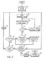
- FIG. 2is a flow chart of the steps performed with the workstation of FIG. 1 to produce a three-dimensional treatment zone image
- FIG. 3is a pictorial representation of patient reference points and a boundary point image of an exemplary treatment zone produced with the workstation of FIG. 1 ;
- FIG. 4is a pictorial representation of a treatment zone
- FIG. 5is a pictorial representation of a radiation treatment system to which three-dimensional treatment zone images produced on the workstation of FIG. 1 may be exported;
- FIG. 6is a flow chart which describes the operation of the radiation treatment system of FIG. 5 ;
- FIG. 7is a display which is produced by the radiation treatment system of FIG. 5 to assist in planning the treatment process.
- a patient 1 having a breast tumor 2will typically undergo an operation in which the tumor 2 is biopsied or resected.
- the present inventionis a method and system that enables the surgeon to mark the location of the tumor and produce an image of a region to be treated that can be conveyed and used in connection with subsequent radiation therapy.
- a surgical probe, or instrument 3is held by the surgeon and used to mark locations in the patient 1 .
- the instrument 3forms part of an optical tracking system (“OTS”) that includes a sensing unit 4 mounted above the patient 1 .
- OTSoptical tracking system
- At least two light emitting diodes 5 mounted on the handle of the surgical instrument 3emit continuous streams of pulsed infrared signals which are sensed by a plurality of infrared sensors 6 mounted on the sensing unit 4 .
- the instrument 3 and sensing unit 4are both connected to a computer workstation 7 , which controls the timing and synchronization of the pulse emissions from LEDs 5 and the recording and processing of the infrared signals received by detectors 6 .
- the computer workstation 7includes a processor 20 which executes program instructions stored in a memory 22 that forms part of a storage system 23 .
- the processor 20is a commercially available device designed to operate with one of the Microsoft Corporation Windows operating systems. It includes internal memory and I/O control to facilitate system integration and integral memory management circuitry for handling all external memory 22 .
- the processor 20also includes a PCI bus driver which provides a direct interface with a 32-bit PCI bus 24 .
- the PCI bus 24is an industry standard bus that transfers 32-bits of data between the processor 20 and a number of peripheral controller cards. These include a PCI EIDE controller 26 which provides a high-speed transfer of data to and from a CD ROM drive 28 and a disc drive 30 .
- a graphics controller 34couples the PCI bus 24 to a CRT monitor 12 through a standard VGA connection 36 , and a keyboard and mouse controller 38 receives data that is manually input through a keyboard and mouse 14 .
- the PCI bus 24also connects to a communications controller 40 .
- the controller 40connects to an intranet that links the workstation 7 to other institution systems such as imaging systems, PAC systems and treatment systems.
- the sensing unit 4interfaces with the PCI bus 24 through an optical sensor circuit 42
- the instrument 3interfaces with the PCI bus 24 through a surgical instrument circuit 44 .
- An OTS program executed by the processor 20operates the surgical instrument 3 and sensing unit 4 to generate data indicating the location and orientation of the tip of the instrument 3 with respect to its coordinate system.
- This instrument position datais produced on a real time continuous basis, so that as the surgical instrument 3 is moved, its position and orientation are continually tracked and recorded by the sensing unit 4 .
- Position and orientation dataare produced whenever a push button switch 9 on the instrument 3 is depressed.
- the OTSis preferably of the type known as the “Flash Point 3-D Optical Localizer”, which is commercially available from Image Guided Technologies of Boulder, Colo. and similar to the systems described in U.S. Pat. Nos. 5,627,857 and 5,622,170.
- the inventionis not limited, however, to the particular type of tracking system used and other modalities may also be used.
- the processor 20also executes a program which interacts with the surgeon to produce a three-dimensional treatment zone image.
- the first step in this processis to establish reference points in the patient using the instrument 3 .
- This stepcan be performed in two ways.
- the instrumentmay be moved to easily identifiable, fixed points in the patient. For example, such points might be vascular branch points and small skeletal landmarks that surround a tumor in the pelvis.
- the button 9is depressed to record and store the patient reference point.
- the surgeonmay record the identity of this anatomic landmark which is stored along with the reference point data. As shown in FIG.
- the first reference point 102serves as the origin of the OTS coordinate system and at least two additional patient reference points 104 and 106 surround the region containing the tumor 2 indicated generally at 108 .
- These patient reference pointsmay be indicated on the treatment zone image with different shaped icons so that each patient reference point can be associated with the proper anatomical landmark description.
- a second method for establishing the patient reference pointsis to implant fiducials at locations around the tumor. This method is preferred in clinical situations such as breast cancer where the tumor is surrounded by soft tissues and there are few fixed anatomical landmarks available.
- the fiducialis implanted using the instrument 3 , and when a fiducial is released, the button 9 is depressed to record its position.
- fiducialsmay be placed via a simple needle and trochar loading system. With this approach, or if surgical clips are used as fiducials, once the fiducials are placed, their locations are recorded as described above using the tip of the instrument 3 .
- fiducialsavailable and the particular type used will depend primarily on the capabilities of the planning system or treatment system to which the treatment zone image is exported.
- the fiducialsmay be opaque to x-rays if the treatment system employs a CT image to register its coordinate system with the patient.
- the fiducialsmay reflect ultrasound if an ultrasound image is used for treatment system registration.
- a radio frequency positioning systemas described in patent application publication US 2004/0133101A1 entitled “Guided Radiation Therapy System” may be used in lieu of a medical image to register the treatment system, in which case the fiducials used may be RFID tags that emit radio frequency signals when interrogated.
- the three-dimensional contour of the treatment zoneis marked using the instrument 3 .
- the tip of instrument 3is placed at a location by the surgeon and the button 9 is depressed and released to record and store the position data.
- These datarepresent the location of the boundary point as measured from the origin of the OTS coordinate system established by the first patient reference point 102 .
- an updated imageis then output to display 12 that depicts the selected boundary points that have been marked and the surrounding patient reference points 102 , 104 and 106 .
- this imagemay show only the boundary points 108 that have been identified so that it can be updated very fast. This enables the surgeon to depress and release the button 9 very rapidly to record boundary points and see their three-dimensional disposition evolve. This “boundary point” image may be revolved to view it from any angle.
- the operatoris then given an opportunity to edit the acquired data point.
- the data pointcan either be deleted, or it can be manually moved. In either case, the system loops back to update the displayed image at process block 112 . It is contemplated that the surgeon will quickly identify the outline of the treatment zone by marking from 6 to 50 points in this manner.
- the surgeonmay elect to produce a 3D treatment zone image as indicated at decision block 117 .
- a button(not shown) is depressed to do this, and as indicated at process block 119 , a cubic spline interpolation produces a 3D surface which smoothly connects the boundary points.
- This 3D treatment zone boundary surfacecan be rotated in space to view it from any desired angle.
- the maximum diameter of the 3D treatment zone boundaryis also automatically calculated and displayed.
- the surgeonis given the opportunity to accept or reject the treatment drawing at decision block 120 . If the drawing is not complete, the system loops back to mark additional boundary points at process block 110 . If the drawing is finished but not accepted, the drawing is erased as indicated at process block 122 and the system loops back to start re-acquiring boundary points for a new image.
- additional regionsmay be, for example, a region near the treatment zone previously described which contains critical tissues that should not be exposed to significant radiation.
- the systemloops back to acquire the boundary points for the additional region which are stored as a separate image. This can be repeated to produce images for additional regions if needed.
- DICOM-RTis a standard that can be exported to commercially available medical systems over the intranet.
- the treatment zone imagemay be exported and used in a number of different systems.
- One such systemis a radiation therapy planning system, which is a workstation that enables images to be imported and used to plan further treatment.
- the imported treatment zone imageis registered with another, anatomic image which is also imported into the therapy planning system.
- the fiducials that appear in both imagesare used to register them and the result is an anatomic image of the patient with the treatment zone superimposed over it.
- the transparency of the treatment zone imagecan be changed to see the underlying anatomy. It can then be used as a target structure, or an object of avoidance structure, for radiation therapy planning.
- Prior to or after exportationthe thickness of the 3D treatment zone image can be increased, symmetrically in each direction beyond the image, for better viewing within CT images.
- additional thicknesscan be added in one direction from the 3D treatment zone image.
- a surgeonmight create an image on the surface of an anatomic structure or tissue where she is concerned about her ability to fully resect, where she is concerned about the presence of microscopic residual disease, or where frozen section analysis reveals the presence of residual disease that cannot be resected.
- thicknesscan be added deep to the drawing to represent the suspected degree of invasion into the anatomic structure or tissue.
- the treatment zone imagemay also be imported by a radiation emitting system to assist in administering radiation to the patient.
- a radiation therapy systemgenerally includes a gantry which can be swiveled around a horizontal axis of rotation in the course of a therapeutic treatment.
- a linear acceleratoris located in the gantry for generating a high energy radiation beam for therapy.
- This high energy radiation beamcan be an electron beam or photon (X-ray) beam.
- this radiation beamis trained on one zone of a patient lying in the isocenter of the gantry rotation.
- a beam shielding devicesuch as a plate arrangement or a collimator, is typically provided in the trajectory of the radiation beam between the radiation source and the patient.
- a plate arrangementis a set of four plates that can be used to define an opening for the radiation beam.
- a beam shielding devicecan include multiple leaves (commonly called “multileaves”), for example, a plurality of relatively thin plates or rods, typically arranged as opposing leaf pairs.
- the platesthemselves are formed of a relatively dense and radiation impervious material and are generally independently positionable to delimit the radiation beam.
- the electron beamsare usually shaped via the placement of cylindrical electron cones, circular or elliptical, mounted in the treatment head. The size of the electron-treated area is controlled via selection of an electron cone of desired diameter.
- the beam shielding devicedefines a field on the object to which a prescribed amount of radiation is to be delivered.
- the usual treatment field shaperesults in a three-dimensional treatment volume which includes segments of normal tissue, thereby limiting the dose that can be given to a tumor located at the isocenter. Avoidance of delivery of radiation to the organs surrounding and overlying the tumor determines the dosage that can be delivered to the tumor.
- Intra-operative linear accelerator-based radiation therapygenerally involves the administration of electrons via a single direct, en face field.
- a key advantage of delivering radiation therapy intra-operativelyis the ability of the surgeon to move structures that are radiosensitive out of the direct path of the electrons and apply a heavier dose to the target tissues. Often, therefore, the surface of the anatomic structure or tissue felt to be at high risk for harboring gross or microscopic residual cancer after gross total or partial resection is exposed directly to the electron beam. Based on the thickness of the residual cancer, and the likely depth of invasion of residual gross or microscopic cancer deep to the surface of the visualized organ or tissue at risk, an electron energy is chosen that will deliver sufficient dose to the area at risk, with rapid dose fall-off deep to the area at risk.
- an electron cone of optimal diameter for coverage of the treatment zone with minimization of dose delivered to surrounding structuresis chosen and mounted to the treatment head.
- the linear acceleratoris moved into proper position to deliver an electron beam to the 3D treatment zone.
- an attemptis made to place the electron cone in position perpendicular to the surface of the exposed organ or tissue at risk. The patient is then irradiated.
- the 3D treatment zone imageis used to help aim the electron beam.
- the treatment systemincludes an alignment apparatus such as that described in the above-cited published US patent application which aligns the treatment system with the patient. This is done using the implanted fiducials. As a result, the electron cone produced by the treatment system is registered with the patient.
- the imported treatment zone imageis also aligned with the patient using the patient reference points in the image and the fiducials implanted in the patient. As a result, the treatment zone image can be registered with an image of the electron cone produced on a display located near the surgeon and radiation oncologist.
- the linear acceleratoris brought into proper position such that the 3D treatment zone depicted on the display is aligned within the displayed border of the electron cone.
- the electron coneis positioned to abut the surface of the organ or tissue to be treated and the angle of the gantry, along with the position of the linear accelerator relative to the patient is adjusted as necessary.
- the desired doseis delivered.
- the 3D treatment zone imagethus serves as a target on the display at which the liner acceleration may be aimed.
- the treatment zone imagemay also be used in a post-operative radiation therapy system.
- the post-operative delivery of radiation by a radiation therapy deviceis prescribed and approved by a radiation oncologist.
- the prescriptionis a definition of, for example, a particular volume and the level of radiation permitted to be delivered to that volume, from each of usually multiple treatment fields.
- the present inventionenables this prescription to be more accurately defined by providing a three-dimensional treatment zone image that is registered with reference points in the patient, and that can be registered with the radiation beam produced by the therapy device.
- Actual operation of the radiation equipmentis normally done by a therapist. When the therapist administers the actual delivery of the radiation treatment as prescribed by the radiation oncologist, the radiation-emitting device is programmed to deliver that specific treatment.
- a three dimensional treatment zone imageis shown.
- the amount of radiation to be delivered to the volume 130is not uniform throughout the volume, however. Typically, the amount of radiation to be delivered is highest in the center and decreases outwardly, though not necessarily uniformly. Thus, for example, voxels 130 a and 130 b could receive different levels of radiation.
- the goal of radiation therapyis to deliver as close a dosage as possible to the prescribed dosage requirements at each of the voxels 130 a , 130 b etc.
- the goal of treatment optimizationis to determine the best way to achieve this treatment fitting.
- Treatment fittingis accomplished by applying radiation at a series of different gantry angles. The leaves of a multi-leaf collimator and/or other shielding device(s) delimit the radiation beam at particular angles and thus define the radiation field for the particular gantry angle.
- the radiation treatment apparatus 201is representative of, for example, the MevatronTM series of machines available from Siemens Medical Systems, Inc.
- the radiation treatment system 201includes a beam shielding device (not shown) within a treatment head 204 , a control unit (not shown) in a housing 209 and a treatment unit 200 .
- the radiation treatment apparatus 201includes a gantry 206 which can be swiveled around a horizontal axis of rotation 208 in the course of a therapeutic treatment.
- the treatment head 204is fastened to projection of the gantry 206 .
- a linear acceleratoris located in the gantry 206 to generate the high powered radiation required for the therapy.
- the axis of the radiation bundle emitted from the linear accelerator and the gantry 206is designated by 210 . Electron, photon or any other detectable radiation can be used for the therapy. In the post-operative setting, photons are almost always used.
- the radiation beamis trained on a treatment zone 212 of a patient 213 who is to be treated and who lies at the isocenter of the gantry rotation.
- the rotational axis 208 of the gantry 206 , the rotational axis 214 of a treatment table 216 , and the beam axis 210intersect at the isocenter.
- the radiation treatment system 201also includes a central treatment processing or control unit 200 which is typically located apart from the radiation treatment apparatus 201 .
- the treatment unit 200may be a Windows NT workstation, for example.
- the radiation treatment apparatus 201is normally located in a different room to protect the therapist from radiation.
- the treatment unit 200includes output devices such as at least one visual display unit or monitor 270 and an input device such as a keyboard 219 or other input devices such as a mouse or trackball (not shown). Data can be input also through data carriers such as data storage devices or through an institutional Intranet connection. By using the keyboard 219 or other input device, the therapist enters into the treatment unit 200 the data that defines the radiation to be delivered to the patient. On the screen of a monitor 71 various data can be displayed before and during the treatment as will be described below.
- the treatment apparatus 201has an array of x-ray detectors 207 supported by the gantry 206 and positioned opposite the treatment head 4 .
- An image of the treatment zonecan be acquired and displayed on the monitor 271 by emitting a radiation beam from the treatment head 204 at a low level and detecting the attenuation of the radiation beam that passes through the patient 213 to the detectors 207 .
- the gantry 206is rotated to acquire attenuation measurements at a series of view angles, and from these measurements a three-dimensional image of the region around the system isocenter is reconstructed.
- this limited imaging capabilityis employed to produce an image of the patient that is aligned with the treatment system isocenter. Or stated another way, this image depicts the patient anatomy that is the target of the treatment system. The field of view of this image is large enough to see anatomical landmarks or implanted fiducials that surround the target tissues.
- the first step in treating a patient according to the present inventionis to place the patient on the table 216 as indicated at process block 150 and position the patient such that the tumor to be radiated is at the system isocenter. Precise alignment is not likely at this time, but at least the tumor should be in the field of view of the image to be acquired with the treatment system 201 .
- the 3D treatment zone imageis then imported over the Intranet along with any other treatment prescription data from the oncologist.
- a scanis then performed with the treatment apparatus to acquire an image of the patient. This image will depict the treatment zone and surrounding tissues as well as any anatomic landmarks that were identified or fiducials that were implanted in the patient.
- the next stepis to register the imported treatment zone image with the patient image as indicated at process block 156 . This can be done manually by right clicking and moving the 3D treatment zone image until the three or more reference points therein are aligned with the anatomical landmarks or implanted fiducials depicted in the patient image. This registration step may also be done automatically using programs such as that described in U.S. Pat. No. 6,408,107 entitled “Rapid Convolution Based Large Deformation Image Matching Via Landmark And Volume Imagery”, which is incorporated herein by reference.
- the prescribed treatment informationis then entered into the treatment unit 200 .
- the radiation treatmentis comprised of a series of exposures to a radiation field of prescribed strength, duration, gantry angle and field size.
- a corresponding icon 168 - 172is produced on the display 271 to show the radiation field that will be produced relative to the treatment zone image 166 .
- These treatment exposurescan be easily edited to insure that all portions of the treatment region receive their prescribed dose. Also, if any high risk tissues were identified by the surgeon, these will also appear in the imported image and be displayed as indicated by the region 174 . In planning the series of treatment exposures, it is relatively easy to select gantry angles and field sizes that will avoid exposing this region 174 .
- the 3D treatment zone imagemay be employed with many different treatment planning and treatment delivery systems, some of them used intra-operative and some of them used post-operative.
- the maximum clinical valueis achieved when the treatment zone image and the patient are registered with each other, with the images used for treatment planning, and with the coordinate system of the treatment device such that the treatment zone image can serve as an accurate target for treatment planning and delivery.
- the present inventionmay also be employed with systems that register the tracking system with pre-operatively obtained images of the patient.
- instrument 3is visible on display 12 intra-operatively within or relative to the pre-operative images.
- Examples of such systemsinclude the VectorVision® navigation system manufactured by BrainLAB, used for brain tumor resections, along with an intrabody navigation system that uses electromagnetic radiation to track the position of a bronchoscope relative to pre-operative images, described in U.S. Pat. No. 6,593,884 (entitled “Intrabody navigation system for medical applications”).
- the pre-operative imageis imported to the workstation 7 and presented on CRT display 12 .
- the tracking systemis registered with this image by placing the tip of instrument 3 at different landmark locations on the patient 1 and moving the displayed image until the same anatomical landmarks therein are aligned with the tracking system landmarks also displayed on the CRT 12 .
- 3D treatment zonesare drawn with the tip of the instrument 3 as described above and the resulting 3D treatment zone is visualized on display 12 with the imported image as it is being created.
- the registered pre-operative images in this alternative embodimentserve as the patient reference points and are stored as part of the treatment zone image.
- the use of fiducials or anatomic landmarks for registrationis optional but not necessary.
- the registration of the treatment zone imagewill be accomplished in the subsequent treatment system by registering the accompanying anatomical “patient reference points” image with an image acquired using an imaging system that is integral with the treatment system as described above. See also U.S. Pat. Nos. 5,418,827 and 5,661,773 which disclose the use of a CT system to perform the imaging function where better quality images of the patient are acquired. Such registration of the two anatomical images can be performed automatically using commercially available image registration software.
- the imported treatment zone imagewithout the need for acquiring an image of the patient.
- fiducialsthat passively emit radio frequency signals (each fiducial with a unique signal) may be implanted in the patient.
- the 3D treatment zone imagesmay be created and registered relative to the RF fiducials, using methods described above.
- An RF tracking systemsuch as that described in the above-cited US patent application can be used to locate the positions of the RF fiducials relative to the treatment system isocenter.
- the 3D treatment zone imagecan then be aligned with these locations using the patient reference points therein.
- the 3D treatment zone workstationcan be used exclusively for generating, registering, viewing, and exporting 3D treatment zones. Alternatively, it can exist as part of a system used for multiple cancer-related intra-operative functions. Ultrasound can be integrated with the cart containing the workstation, for intra-operative imaging. When the ultrasound probe is optically tracked, ultrasound can be used for 3D localization of the fiducials to which the 3D treatment zone is registered. In addition, however, ultrasound can also be used to identify existing structures intra-operatively for surgical management, but also for later radiation therapy or other targeting. As an example, liver metastases are often best imaged via intra-operative ultrasound.
- radio-opaque fiducialscan be implanted near the metastasis.
- the ultrasound image of the tumorcan be registered to the fiducials.
- the fiducialsare identified later in the anatomic images imported to a radiation therapy treatment planning system, the ultrasound image of the metastasis can be viewed in the images relative to the fiducials, and then targeted.
- the ultrasound image of the metastasiscan be viewed and tracked relative to the fiducials and field borders.
- the intra-operative ultrasound imagescan be similarly viewed, tracked, and targeted.
- the workstation used for 3D treatment zone generationcan also be integrated with an intra-operative soft tissue guidance system that tracks target location, orientation, and shape relative to fiducials, and relative to surgical instruments.
- an intra-operative soft tissue guidance systemthat tracks target location, orientation, and shape relative to fiducials, and relative to surgical instruments.
- the fiducials to which 3D treatment zones, ultrasound images, or other images are registeredcan change in orientation or position relative to the other fiducials.
- the position of each point used to generate the 3D treatment zoneis therefore calculated, relative to each fiducial.
- the points of the 3D treatment zoneare repositioned by software which calculates the most likely positions of the points, based on the new fiducial positions.
- the outer border of the imageis then “morphed” so that its outer surface continues to pass through the points.
- the positions of representative points forming the outer surfaces of other tumor images, such as ultrasound images,can be calculated relative to the fiducials, so that these images can be similarly morphed as the fiducials change in relative position and orientation.
- the outer borders of physiologic imagessuch as PET or MRI or SPECT images of tumors can be imported relative to the fiducials, and similarly morphed as the fiducials change in relative position and orientation.
- the internal anatomycan be similarly morphed as the fiducials change in relative position and orientation.
- the internal physiology of tumorscan be displayed isonumerically, such that voxels internal to the borders of a tumor image that are of equal or similar intensity are connected by three-dimensional contour lines.
- These contoursrepresenting the isophysiologic areas within a tumor similar to the way elevation contours represent areas of equal elevation on a topographic map, demonstrate physiologic gradients and other forms of physiologic heterogeneity within tumors.
- These internal isonumeric contourscan be similarly morphed as the fiducials change in relative position and orientation.
- physiologic imagescan be used for real time targeting of radiation therapy. However, they can also be used for surgical targeting, with the outer borders or internal contours serving as dissection planes. If desired, a selected amount of surgical margin can be added to any border or contour, and similarly morphed as the tissue is surgically manipulated. These images can also be merged with ultrasound or other images, all of which are registered to the fiducials, to form composite images, still registered to the fiducials.
Landscapes
- Health & Medical Sciences (AREA)
- Engineering & Computer Science (AREA)
- Life Sciences & Earth Sciences (AREA)
- Biomedical Technology (AREA)
- Public Health (AREA)
- Animal Behavior & Ethology (AREA)
- Veterinary Medicine (AREA)
- Nuclear Medicine, Radiotherapy & Molecular Imaging (AREA)
- Surgery (AREA)
- General Health & Medical Sciences (AREA)
- Medical Informatics (AREA)
- Molecular Biology (AREA)
- Heart & Thoracic Surgery (AREA)
- Robotics (AREA)
- Pathology (AREA)
- Radiology & Medical Imaging (AREA)
- Radiation-Therapy Devices (AREA)
- Apparatus For Radiation Diagnosis (AREA)
Abstract
Description
Claims (15)
Priority Applications (5)
| Application Number | Priority Date | Filing Date | Title |
|---|---|---|---|
| US10/910,483US8055323B2 (en) | 2003-08-05 | 2004-08-03 | Stereotactic system and method for defining a tumor treatment region |
| CA2575759ACA2575759C (en) | 2004-08-03 | 2005-08-01 | Tumor treatment identification system |
| EP05778284AEP1786517B1 (en) | 2004-08-03 | 2005-08-01 | Tumor treatment identification system |
| AT05778284TATE529161T1 (en) | 2004-08-03 | 2005-08-01 | TUMOR TREATMENT IDENTIFICATION SYSTEM |
| PCT/US2005/027393WO2006017489A2 (en) | 2004-08-03 | 2005-08-01 | Tumor treatment identification system |
Applications Claiming Priority (4)
| Application Number | Priority Date | Filing Date | Title |
|---|---|---|---|
| US49279603P | 2003-08-05 | 2003-08-05 | |
| US50811703P | 2003-10-02 | 2003-10-02 | |
| US53463304P | 2004-01-07 | 2004-01-07 | |
| US10/910,483US8055323B2 (en) | 2003-08-05 | 2004-08-03 | Stereotactic system and method for defining a tumor treatment region |
Publications (2)
| Publication Number | Publication Date |
|---|---|
| US20050033108A1 US20050033108A1 (en) | 2005-02-10 |
| US8055323B2true US8055323B2 (en) | 2011-11-08 |
Family
ID=39032310
Family Applications (1)
| Application Number | Title | Priority Date | Filing Date |
|---|---|---|---|
| US10/910,483Expired - Fee RelatedUS8055323B2 (en) | 2003-08-05 | 2004-08-03 | Stereotactic system and method for defining a tumor treatment region |
Country Status (5)
| Country | Link |
|---|---|
| US (1) | US8055323B2 (en) |
| EP (1) | EP1786517B1 (en) |
| AT (1) | ATE529161T1 (en) |
| CA (1) | CA2575759C (en) |
| WO (1) | WO2006017489A2 (en) |
Cited By (19)
| Publication number | Priority date | Publication date | Assignee | Title |
|---|---|---|---|---|
| US20100049549A1 (en)* | 2008-08-22 | 2010-02-25 | Nelms Benjamin E | Patient-customized medical treatment education system and methods |
| US20160058521A1 (en)* | 2007-11-21 | 2016-03-03 | Edda Technology, Inc. | Method and system for adjusting interactive 3d treatment zone for percutaneous treatment |
| US9408571B2 (en) | 2012-06-18 | 2016-08-09 | Carnegie Mellon University | Apparatus and method for implantation of devices into soft tissue |
| US9530219B2 (en) | 2014-07-02 | 2016-12-27 | Covidien Lp | System and method for detecting trachea |
| US9603668B2 (en) | 2014-07-02 | 2017-03-28 | Covidien Lp | Dynamic 3D lung map view for tool navigation inside the lung |
| US9754367B2 (en) | 2014-07-02 | 2017-09-05 | Covidien Lp | Trachea marking |
| US9770216B2 (en) | 2014-07-02 | 2017-09-26 | Covidien Lp | System and method for navigating within the lung |
| US9836848B2 (en) | 2014-07-02 | 2017-12-05 | Covidien Lp | System and method for segmentation of lung |
| US10709352B2 (en) | 2015-10-27 | 2020-07-14 | Covidien Lp | Method of using lung airway carina locations to improve ENB registration |
| US10772532B2 (en) | 2014-07-02 | 2020-09-15 | Covidien Lp | Real-time automatic registration feedback |
| USD916749S1 (en) | 2014-07-02 | 2021-04-20 | Covidien Lp | Display screen or portion thereof with graphical user interface |
| US10986990B2 (en) | 2015-09-24 | 2021-04-27 | Covidien Lp | Marker placement |
| US11224392B2 (en) | 2018-02-01 | 2022-01-18 | Covidien Lp | Mapping disease spread |
| US20220151688A1 (en)* | 2008-04-29 | 2022-05-19 | Virginia Tech Intellectual Properties Inc. | System and method for estimating tissue heating of a target ablation zone for electrical-energy based therapies |
| US12089902B2 (en) | 2019-07-30 | 2024-09-17 | Coviden Lp | Cone beam and 3D fluoroscope lung navigation |
| US12173280B2 (en) | 2008-04-29 | 2024-12-24 | Virginia Tech Intellectual Properties, Inc. | Methods of reducing adverse effects of non-thermal ablation |
| US12232792B2 (en) | 2011-07-15 | 2025-02-25 | Virginia Tech Intellectual Properties, Inc. | Device and method for electroporation based treatment |
| US12303182B2 (en) | 2016-11-17 | 2025-05-20 | Angiodynamics, Inc. | Techniques for irreversible electroporation using a single-pole tine-style internal device communicating with an external surface electrode |
| US12390262B2 (en) | 2018-03-13 | 2025-08-19 | Virginia Tech Intellectual Properties, Inc. | Treatment planning system for immunotherapy enhancement via non-thermal ablation |
Families Citing this family (60)
| Publication number | Priority date | Publication date | Assignee | Title |
|---|---|---|---|---|
| US20040015079A1 (en) | 1999-06-22 | 2004-01-22 | Teratech Corporation | Ultrasound probe with integrated electronics |
| US9402601B1 (en)* | 1999-06-22 | 2016-08-02 | Teratech Corporation | Methods for controlling an ultrasound imaging procedure and providing ultrasound images to an external non-ultrasound application via a network |
| US20060063998A1 (en)* | 2004-09-21 | 2006-03-23 | Von Jako Ron | Navigation and visualization of an access needle system |
| EP1827238A4 (en) | 2004-12-06 | 2009-04-22 | Cambridge Res & Instrmnt Inc | Systems and methods for in-vivo optical imaging and measurement |
| WO2007087447A2 (en)* | 2006-01-25 | 2007-08-02 | Health Beacens, Inc. | Surgical procedure |
| US20080033286A1 (en)* | 2006-08-02 | 2008-02-07 | Civco Medical Instruments Co., Inc. | Fiducial marker for imaging localization and method of using the same |
| EP1955733A1 (en)* | 2007-02-06 | 2008-08-13 | Siemens Schweiz AG | Device for the physical location of a moveable body part |
| US20090003666A1 (en)* | 2007-06-27 | 2009-01-01 | Wu Dee H | System and methods for image analysis and treatment |
| US8088072B2 (en) | 2007-10-12 | 2012-01-03 | Gynesonics, Inc. | Methods and systems for controlled deployment of needles in tissue |
| US9076203B2 (en)* | 2007-11-26 | 2015-07-07 | The Invention Science Fund I, Llc | Image guided surgery with dynamic image reconstruction |
| US8973584B2 (en) | 2009-02-13 | 2015-03-10 | Health Beacons, Inc. | Method and apparatus for locating passive integrated transponder tags |
| US8915833B1 (en)* | 2011-02-15 | 2014-12-23 | Velayudhan Sahadevan | Image guided intraoperative simultaneous several ports microbeam radiation therapy with microfocus X-ray tubes |
| US11871901B2 (en) | 2012-05-20 | 2024-01-16 | Cilag Gmbh International | Method for situational awareness for surgical network or surgical network connected device capable of adjusting function based on a sensed situation or usage |
| US8939153B1 (en) | 2013-03-15 | 2015-01-27 | Health Beacons, Inc. | Transponder strings |
| JP6604977B2 (en) | 2014-07-02 | 2019-11-13 | コヴィディエン リミテッド パートナーシップ | System that provides distance and orientation feedback during 3D navigation |
| US11227427B2 (en)* | 2014-08-11 | 2022-01-18 | Covidien Lp | Treatment procedure planning system and method |
| WO2016032910A1 (en) | 2014-08-24 | 2016-03-03 | Health Beacons, Inc. | Probe for determining magnetic marker locations |
| WO2018075935A1 (en)* | 2016-10-21 | 2018-04-26 | Mako Surgical Corp. | Systems and tools for use with surgical robotic manipulators |
| CN115715689B (en) | 2016-11-11 | 2025-01-17 | 杰尼索尼克斯公司 | Tissue controlled treatment and dynamic interaction and comparison with tissue and/or treatment data |
| US11925373B2 (en) | 2017-10-30 | 2024-03-12 | Cilag Gmbh International | Surgical suturing instrument comprising a non-circular needle |
| US11291510B2 (en) | 2017-10-30 | 2022-04-05 | Cilag Gmbh International | Method of hub communication with surgical instrument systems |
| US11510741B2 (en) | 2017-10-30 | 2022-11-29 | Cilag Gmbh International | Method for producing a surgical instrument comprising a smart electrical system |
| US11109866B2 (en) | 2017-12-28 | 2021-09-07 | Cilag Gmbh International | Method for circular stapler control algorithm adjustment based on situational awareness |
| US11864728B2 (en) | 2017-12-28 | 2024-01-09 | Cilag Gmbh International | Characterization of tissue irregularities through the use of mono-chromatic light refractivity |
| US11969216B2 (en) | 2017-12-28 | 2024-04-30 | Cilag Gmbh International | Surgical network recommendations from real time analysis of procedure variables against a baseline highlighting differences from the optimal solution |
| US12062442B2 (en) | 2017-12-28 | 2024-08-13 | Cilag Gmbh International | Method for operating surgical instrument systems |
| US12396806B2 (en) | 2017-12-28 | 2025-08-26 | Cilag Gmbh International | Adjustment of a surgical device function based on situational awareness |
| US20190201090A1 (en) | 2017-12-28 | 2019-07-04 | Ethicon Llc | Capacitive coupled return path pad with separable array elements |
| US12096916B2 (en)* | 2017-12-28 | 2024-09-24 | Cilag Gmbh International | Method of sensing particulate from smoke evacuated from a patient, adjusting the pump speed based on the sensed information, and communicating the functional parameters of the system to the hub |
| US11076921B2 (en) | 2017-12-28 | 2021-08-03 | Cilag Gmbh International | Adaptive control program updates for surgical hubs |
| US11304699B2 (en) | 2017-12-28 | 2022-04-19 | Cilag Gmbh International | Method for adaptive control schemes for surgical network control and interaction |
| US11998193B2 (en) | 2017-12-28 | 2024-06-04 | Cilag Gmbh International | Method for usage of the shroud as an aspect of sensing or controlling a powered surgical device, and a control algorithm to adjust its default operation |
| US11202570B2 (en) | 2017-12-28 | 2021-12-21 | Cilag Gmbh International | Communication hub and storage device for storing parameters and status of a surgical device to be shared with cloud based analytics systems |
| US11179175B2 (en) | 2017-12-28 | 2021-11-23 | Cilag Gmbh International | Controlling an ultrasonic surgical instrument according to tissue location |
| US11324557B2 (en) | 2017-12-28 | 2022-05-10 | Cilag Gmbh International | Surgical instrument with a sensing array |
| US11896443B2 (en) | 2017-12-28 | 2024-02-13 | Cilag Gmbh International | Control of a surgical system through a surgical barrier |
| US12127729B2 (en) | 2017-12-28 | 2024-10-29 | Cilag Gmbh International | Method for smoke evacuation for surgical hub |
| US11464559B2 (en) | 2017-12-28 | 2022-10-11 | Cilag Gmbh International | Estimating state of ultrasonic end effector and control system therefor |
| US11612444B2 (en) | 2017-12-28 | 2023-03-28 | Cilag Gmbh International | Adjustment of a surgical device function based on situational awareness |
| US11257589B2 (en) | 2017-12-28 | 2022-02-22 | Cilag Gmbh International | Real-time analysis of comprehensive cost of all instrumentation used in surgery utilizing data fluidity to track instruments through stocking and in-house processes |
| US11832899B2 (en) | 2017-12-28 | 2023-12-05 | Cilag Gmbh International | Surgical systems with autonomously adjustable control programs |
| US11969142B2 (en) | 2017-12-28 | 2024-04-30 | Cilag Gmbh International | Method of compressing tissue within a stapling device and simultaneously displaying the location of the tissue within the jaws |
| US11896322B2 (en) | 2017-12-28 | 2024-02-13 | Cilag Gmbh International | Sensing the patient position and contact utilizing the mono-polar return pad electrode to provide situational awareness to the hub |
| US11633237B2 (en) | 2017-12-28 | 2023-04-25 | Cilag Gmbh International | Usage and technique analysis of surgeon / staff performance against a baseline to optimize device utilization and performance for both current and future procedures |
| US11311306B2 (en) | 2017-12-28 | 2022-04-26 | Cilag Gmbh International | Surgical systems for detecting end effector tissue distribution irregularities |
| US11013563B2 (en) | 2017-12-28 | 2021-05-25 | Ethicon Llc | Drive arrangements for robot-assisted surgical platforms |
| US20190201112A1 (en) | 2017-12-28 | 2019-07-04 | Ethicon Llc | Computer implemented interactive surgical systems |
| WO2019133144A1 (en) | 2017-12-28 | 2019-07-04 | Ethicon Llc | Detection and escalation of security responses of surgical instruments to increasing severity threats |
| US11026751B2 (en) | 2017-12-28 | 2021-06-08 | Cilag Gmbh International | Display of alignment of staple cartridge to prior linear staple line |
| US11857152B2 (en) | 2017-12-28 | 2024-01-02 | Cilag Gmbh International | Surgical hub spatial awareness to determine devices in operating theater |
| US20190206569A1 (en) | 2017-12-28 | 2019-07-04 | Ethicon Llc | Method of cloud based data analytics for use with the hub |
| US11534196B2 (en) | 2018-03-08 | 2022-12-27 | Cilag Gmbh International | Using spectroscopy to determine device use state in combo instrument |
| US11259830B2 (en) | 2018-03-08 | 2022-03-01 | Cilag Gmbh International | Methods for controlling temperature in ultrasonic device |
| US11986233B2 (en) | 2018-03-08 | 2024-05-21 | Cilag Gmbh International | Adjustment of complex impedance to compensate for lost power in an articulating ultrasonic device |
| US11090047B2 (en) | 2018-03-28 | 2021-08-17 | Cilag Gmbh International | Surgical instrument comprising an adaptive control system |
| US11331100B2 (en) | 2019-02-19 | 2022-05-17 | Cilag Gmbh International | Staple cartridge retainer system with authentication keys |
| US20200273563A1 (en) | 2019-02-21 | 2020-08-27 | Theator inc. | Adjusting an operating room schedule |
| EP4235691A3 (en) | 2019-02-21 | 2023-12-27 | Theator Inc. | Systems and methods to enable automatically populating a post-operative report of a surgical procedure |
| US20210093227A1 (en)* | 2019-09-26 | 2021-04-01 | Canon Kabushiki Kaisha | Image processing system and control method thereof |
| US11348682B2 (en) | 2020-04-05 | 2022-05-31 | Theator, Inc. | Automated assessment of surgical competency from video analyses |
Citations (34)
| Publication number | Priority date | Publication date | Assignee | Title |
|---|---|---|---|---|
| US4736307A (en) | 1982-04-21 | 1988-04-05 | Neuroscience, Inc. | Microcomputer-based system for the on-line analysis and topographic display of human brain electrical activity |
| US5373844A (en) | 1993-06-14 | 1994-12-20 | The Regents Of The University Of California | Inverse treatment planning method and apparatus for stereotactic radiosurgery |
| US5418827A (en) | 1993-06-18 | 1995-05-23 | Wisconsin Alumino Research Foundation | Method for radiation therapy planning |
| US5517990A (en)* | 1992-11-30 | 1996-05-21 | The Cleveland Clinic Foundation | Stereotaxy wand and tool guide |
| US5622187A (en) | 1994-09-30 | 1997-04-22 | Nomos Corporation | Method and apparatus for patient positioning for radiation therapy |
| US5661773A (en) | 1992-03-19 | 1997-08-26 | Wisconsin Alumni Research Foundation | Interface for radiation therapy machine |
| US5740802A (en) | 1993-04-20 | 1998-04-21 | General Electric Company | Computer graphic and live video system for enhancing visualization of body structures during surgery |
| US5859891A (en) | 1997-03-07 | 1999-01-12 | Hibbard; Lyn | Autosegmentation/autocontouring system and method for use with three-dimensional radiation therapy treatment planning |
| US5868673A (en) | 1995-03-28 | 1999-02-09 | Sonometrics Corporation | System for carrying out surgery, biopsy and ablation of a tumor or other physical anomaly |
| US5871018A (en) | 1995-12-26 | 1999-02-16 | Delp; Scott L. | Computer-assisted surgical method |
| US6067372A (en) | 1996-02-22 | 2000-05-23 | University Of Pittsburgh | Method and system to enhance robust identification of abnormal regions in radiographs |
| US6104779A (en) | 1994-05-10 | 2000-08-15 | Shepherd; Joseph S. | Radiation therapy and radiation surgery treatment system and methods of use of same |
| US6112112A (en) | 1998-09-18 | 2000-08-29 | Arch Development Corporation | Method and system for the assessment of tumor extent in magnetic resonance images |
| US6167296A (en) | 1996-06-28 | 2000-12-26 | The Board Of Trustees Of The Leland Stanford Junior University | Method for volumetric image navigation |
| US6222544B1 (en) | 1997-10-17 | 2001-04-24 | Siemens Medical Systems, Inc. | Graphical user interface for radiation therapy treatment apparatus |
| US6226352B1 (en) | 1998-09-08 | 2001-05-01 | Veritas Pharmaceuticals, Inc. | System and method for radiographic imaging of tissue |
| US6236875B1 (en) | 1994-10-07 | 2001-05-22 | Surgical Navigation Technologies | Surgical navigation systems including reference and localization frames |
| US6239724B1 (en) | 1997-12-30 | 2001-05-29 | Remon Medical Technologies, Ltd. | System and method for telemetrically providing intrabody spatial position |
| US6258104B1 (en) | 1998-11-04 | 2001-07-10 | Hologic, Inc. | Method and apparatus for removing tissue from a region of interest using stereotactic radiographic guidance |
| US6292578B1 (en) | 1998-02-18 | 2001-09-18 | International Business Machines Corporation | System and method for restoring, describing and graphically displaying noise-corrupted boundaries in tomography images |
| US6335980B1 (en) | 1997-07-25 | 2002-01-01 | Arch Development Corporation | Method and system for the segmentation of lung regions in lateral chest radiographs |
| US6347240B1 (en) | 1990-10-19 | 2002-02-12 | St. Louis University | System and method for use in displaying images of a body part |
| US6398710B1 (en) | 1999-01-06 | 2002-06-04 | Ball Semiconductor, Inc. | Radiation dosimetry system |
| US6405072B1 (en)* | 1991-01-28 | 2002-06-11 | Sherwood Services Ag | Apparatus and method for determining a location of an anatomical target with reference to a medical apparatus |
| US6470207B1 (en) | 1999-03-23 | 2002-10-22 | Surgical Navigation Technologies, Inc. | Navigational guidance via computer-assisted fluoroscopic imaging |
| US6546073B1 (en) | 1999-11-05 | 2003-04-08 | Georgia Tech Research Corporation | Systems and methods for global optimization of treatment planning for external beam radiation therapy |
| US6556695B1 (en) | 1999-02-05 | 2003-04-29 | Mayo Foundation For Medical Education And Research | Method for producing high resolution real-time images, of structure and function during medical procedures |
| US20030211036A1 (en) | 2002-05-07 | 2003-11-13 | Hadassa Degani | Method and apparatus for monitoring and quantitatively evaluating tumor perfusion |
| US6669635B2 (en) | 1999-10-28 | 2003-12-30 | Surgical Navigation Technologies, Inc. | Navigation information overlay onto ultrasound imagery |
| US6675810B2 (en) | 1998-05-14 | 2004-01-13 | Calypso Medical Technologies, Inc. | System and method for bracketing and removing tissue |
| US6681129B2 (en) | 2000-09-29 | 2004-01-20 | Olympus Optical Co., Ltd. | Surgical operation navigation apparatus and method |
| US6694057B1 (en) | 1999-01-27 | 2004-02-17 | Washington University | Method and apparatus for processing images with curves |
| WO2004033041A1 (en) | 2002-10-07 | 2004-04-22 | Nomos Corporation | Method and apparatus for target position verification |
| US20040138556A1 (en) | 1991-01-28 | 2004-07-15 | Cosman Eric R. | Optical object tracking system |
- 2004
- 2004-08-03USUS10/910,483patent/US8055323B2/ennot_activeExpired - Fee Related
- 2005
- 2005-08-01ATAT05778284Tpatent/ATE529161T1/ennot_activeIP Right Cessation
- 2005-08-01WOPCT/US2005/027393patent/WO2006017489A2/enactiveApplication Filing
- 2005-08-01CACA2575759Apatent/CA2575759C/ennot_activeExpired - Fee Related
- 2005-08-01EPEP05778284Apatent/EP1786517B1/ennot_activeExpired - Lifetime
Patent Citations (37)
| Publication number | Priority date | Publication date | Assignee | Title |
|---|---|---|---|---|
| US4736307A (en) | 1982-04-21 | 1988-04-05 | Neuroscience, Inc. | Microcomputer-based system for the on-line analysis and topographic display of human brain electrical activity |
| US6434415B1 (en) | 1990-10-19 | 2002-08-13 | St. Louis University | System for use in displaying images of a body part |
| US6347240B1 (en) | 1990-10-19 | 2002-02-12 | St. Louis University | System and method for use in displaying images of a body part |
| US20040122311A1 (en) | 1991-01-28 | 2004-06-24 | Cosman Eric R. | Surgical positioning system |
| US6405072B1 (en)* | 1991-01-28 | 2002-06-11 | Sherwood Services Ag | Apparatus and method for determining a location of an anatomical target with reference to a medical apparatus |
| US20040138556A1 (en) | 1991-01-28 | 2004-07-15 | Cosman Eric R. | Optical object tracking system |
| US5661773A (en) | 1992-03-19 | 1997-08-26 | Wisconsin Alumni Research Foundation | Interface for radiation therapy machine |
| US5517990A (en)* | 1992-11-30 | 1996-05-21 | The Cleveland Clinic Foundation | Stereotaxy wand and tool guide |
| US5740802A (en) | 1993-04-20 | 1998-04-21 | General Electric Company | Computer graphic and live video system for enhancing visualization of body structures during surgery |
| US5373844A (en) | 1993-06-14 | 1994-12-20 | The Regents Of The University Of California | Inverse treatment planning method and apparatus for stereotactic radiosurgery |
| US5418827A (en) | 1993-06-18 | 1995-05-23 | Wisconsin Alumino Research Foundation | Method for radiation therapy planning |
| US6104779A (en) | 1994-05-10 | 2000-08-15 | Shepherd; Joseph S. | Radiation therapy and radiation surgery treatment system and methods of use of same |
| US6422748B1 (en) | 1994-05-10 | 2002-07-23 | Joseph S. Shepherd | Radiation therapy and radiation surgery treatment system and methods of use of same |
| US5622187A (en) | 1994-09-30 | 1997-04-22 | Nomos Corporation | Method and apparatus for patient positioning for radiation therapy |
| US6236875B1 (en) | 1994-10-07 | 2001-05-22 | Surgical Navigation Technologies | Surgical navigation systems including reference and localization frames |
| US5868673A (en) | 1995-03-28 | 1999-02-09 | Sonometrics Corporation | System for carrying out surgery, biopsy and ablation of a tumor or other physical anomaly |
| US5871018A (en) | 1995-12-26 | 1999-02-16 | Delp; Scott L. | Computer-assisted surgical method |
| US6067372A (en) | 1996-02-22 | 2000-05-23 | University Of Pittsburgh | Method and system to enhance robust identification of abnormal regions in radiographs |
| US6167296A (en) | 1996-06-28 | 2000-12-26 | The Board Of Trustees Of The Leland Stanford Junior University | Method for volumetric image navigation |
| US5859891A (en) | 1997-03-07 | 1999-01-12 | Hibbard; Lyn | Autosegmentation/autocontouring system and method for use with three-dimensional radiation therapy treatment planning |
| US6335980B1 (en) | 1997-07-25 | 2002-01-01 | Arch Development Corporation | Method and system for the segmentation of lung regions in lateral chest radiographs |
| US6222544B1 (en) | 1997-10-17 | 2001-04-24 | Siemens Medical Systems, Inc. | Graphical user interface for radiation therapy treatment apparatus |
| US6239724B1 (en) | 1997-12-30 | 2001-05-29 | Remon Medical Technologies, Ltd. | System and method for telemetrically providing intrabody spatial position |
| US6292578B1 (en) | 1998-02-18 | 2001-09-18 | International Business Machines Corporation | System and method for restoring, describing and graphically displaying noise-corrupted boundaries in tomography images |
| US6675810B2 (en) | 1998-05-14 | 2004-01-13 | Calypso Medical Technologies, Inc. | System and method for bracketing and removing tissue |
| US6226352B1 (en) | 1998-09-08 | 2001-05-01 | Veritas Pharmaceuticals, Inc. | System and method for radiographic imaging of tissue |
| US6112112A (en) | 1998-09-18 | 2000-08-29 | Arch Development Corporation | Method and system for the assessment of tumor extent in magnetic resonance images |
| US6258104B1 (en) | 1998-11-04 | 2001-07-10 | Hologic, Inc. | Method and apparatus for removing tissue from a region of interest using stereotactic radiographic guidance |
| US6398710B1 (en) | 1999-01-06 | 2002-06-04 | Ball Semiconductor, Inc. | Radiation dosimetry system |
| US6694057B1 (en) | 1999-01-27 | 2004-02-17 | Washington University | Method and apparatus for processing images with curves |
| US6556695B1 (en) | 1999-02-05 | 2003-04-29 | Mayo Foundation For Medical Education And Research | Method for producing high resolution real-time images, of structure and function during medical procedures |
| US6470207B1 (en) | 1999-03-23 | 2002-10-22 | Surgical Navigation Technologies, Inc. | Navigational guidance via computer-assisted fluoroscopic imaging |
| US6669635B2 (en) | 1999-10-28 | 2003-12-30 | Surgical Navigation Technologies, Inc. | Navigation information overlay onto ultrasound imagery |
| US6546073B1 (en) | 1999-11-05 | 2003-04-08 | Georgia Tech Research Corporation | Systems and methods for global optimization of treatment planning for external beam radiation therapy |
| US6681129B2 (en) | 2000-09-29 | 2004-01-20 | Olympus Optical Co., Ltd. | Surgical operation navigation apparatus and method |
| US20030211036A1 (en) | 2002-05-07 | 2003-11-13 | Hadassa Degani | Method and apparatus for monitoring and quantitatively evaluating tumor perfusion |
| WO2004033041A1 (en) | 2002-10-07 | 2004-04-22 | Nomos Corporation | Method and apparatus for target position verification |
Cited By (50)
| Publication number | Priority date | Publication date | Assignee | Title |
|---|---|---|---|---|
| US20160058521A1 (en)* | 2007-11-21 | 2016-03-03 | Edda Technology, Inc. | Method and system for adjusting interactive 3d treatment zone for percutaneous treatment |
| US11264139B2 (en)* | 2007-11-21 | 2022-03-01 | Edda Technology, Inc. | Method and system for adjusting interactive 3D treatment zone for percutaneous treatment |
| US12390268B2 (en)* | 2008-04-29 | 2025-08-19 | Virginia Tech Intellectual Properties, Inc. | System and method for estimating tissue heating of a target ablation zone for electrical-energy based therapies |
| US12173280B2 (en) | 2008-04-29 | 2024-12-24 | Virginia Tech Intellectual Properties, Inc. | Methods of reducing adverse effects of non-thermal ablation |
| US20220151688A1 (en)* | 2008-04-29 | 2022-05-19 | Virginia Tech Intellectual Properties Inc. | System and method for estimating tissue heating of a target ablation zone for electrical-energy based therapies |
| US20100049549A1 (en)* | 2008-08-22 | 2010-02-25 | Nelms Benjamin E | Patient-customized medical treatment education system and methods |
| US12232792B2 (en) | 2011-07-15 | 2025-02-25 | Virginia Tech Intellectual Properties, Inc. | Device and method for electroporation based treatment |
| US9408571B2 (en) | 2012-06-18 | 2016-08-09 | Carnegie Mellon University | Apparatus and method for implantation of devices into soft tissue |
| US10350021B2 (en)* | 2012-06-18 | 2019-07-16 | Carnegie Mellon University | Apparatus and method for implantation of devices into soft tissue |
| US10878573B2 (en) | 2014-07-02 | 2020-12-29 | Covidien Lp | System and method for segmentation of lung |
| USD916750S1 (en) | 2014-07-02 | 2021-04-20 | Covidien Lp | Display screen or portion thereof with graphical user interface |
| US9836848B2 (en) | 2014-07-02 | 2017-12-05 | Covidien Lp | System and method for segmentation of lung |
| US9848953B2 (en) | 2014-07-02 | 2017-12-26 | Covidien Lp | Dynamic 3D lung map view for tool navigation inside the lung |
| US9990721B2 (en) | 2014-07-02 | 2018-06-05 | Covidien Lp | System and method for detecting trachea |
| US10062166B2 (en) | 2014-07-02 | 2018-08-28 | Covidien Lp | Trachea marking |
| US10074185B2 (en) | 2014-07-02 | 2018-09-11 | Covidien Lp | System and method for segmentation of lung |
| US10105185B2 (en) | 2014-07-02 | 2018-10-23 | Covidien Lp | Dynamic 3D lung map view for tool navigation |
| US10460441B2 (en) | 2014-07-02 | 2019-10-29 | Covidien Lp | Trachea marking |
| US10646277B2 (en) | 2014-07-02 | 2020-05-12 | Covidien Lp | Methods of providing a map view of a lung or luminal network using a 3D model |
| US10653485B2 (en) | 2014-07-02 | 2020-05-19 | Covidien Lp | System and method of intraluminal navigation using a 3D model |
| US10660708B2 (en) | 2014-07-02 | 2020-05-26 | Covidien Lp | Dynamic 3D lung map view for tool navigation inside the lung |
| US10772532B2 (en) | 2014-07-02 | 2020-09-15 | Covidien Lp | Real-time automatic registration feedback |
| US10776914B2 (en) | 2014-07-02 | 2020-09-15 | Covidien Lp | System and method for detecting trachea |
| US10799297B2 (en) | 2014-07-02 | 2020-10-13 | Covidien Lp | Dynamic 3D lung map view for tool navigation inside the lung |
| US9754367B2 (en) | 2014-07-02 | 2017-09-05 | Covidien Lp | Trachea marking |
| USD916749S1 (en) | 2014-07-02 | 2021-04-20 | Covidien Lp | Display screen or portion thereof with graphical user interface |
| US11877804B2 (en) | 2014-07-02 | 2024-01-23 | Covidien Lp | Methods for navigation of catheters inside lungs |
| US11026644B2 (en) | 2014-07-02 | 2021-06-08 | Covidien Lp | System and method for navigating within the lung |
| US11172989B2 (en) | 2014-07-02 | 2021-11-16 | Covidien Lp | Dynamic 3D lung map view for tool navigation inside the lung |
| US9530219B2 (en) | 2014-07-02 | 2016-12-27 | Covidien Lp | System and method for detecting trachea |
| US9603668B2 (en) | 2014-07-02 | 2017-03-28 | Covidien Lp | Dynamic 3D lung map view for tool navigation inside the lung |
| US9741115B2 (en) | 2014-07-02 | 2017-08-22 | Covidien Lp | System and method for detecting trachea |
| US11361439B2 (en) | 2014-07-02 | 2022-06-14 | Covidien Lp | System and method for detecting trachea |
| US11389247B2 (en) | 2014-07-02 | 2022-07-19 | Covidien Lp | Methods for navigation of a probe inside a lung |
| US11529192B2 (en) | 2014-07-02 | 2022-12-20 | Covidien Lp | Dynamic 3D lung map view for tool navigation inside the lung |
| US11547485B2 (en) | 2014-07-02 | 2023-01-10 | Covidien Lp | Dynamic 3D lung map view for tool navigation inside the lung |
| US11576556B2 (en) | 2014-07-02 | 2023-02-14 | Covidien Lp | System and method for navigating within the lung |
| US9607395B2 (en) | 2014-07-02 | 2017-03-28 | Covidien Lp | System and method for detecting trachea |
| US11583205B2 (en) | 2014-07-02 | 2023-02-21 | Covidien Lp | Real-time automatic registration feedback |
| US11607276B2 (en) | 2014-07-02 | 2023-03-21 | Covidien Lp | Dynamic 3D lung map view for tool navigation inside the lung |
| US9770216B2 (en) | 2014-07-02 | 2017-09-26 | Covidien Lp | System and method for navigating within the lung |
| US11823431B2 (en) | 2014-07-02 | 2023-11-21 | Covidien Lp | System and method for detecting trachea |
| US11672415B2 (en) | 2015-09-24 | 2023-06-13 | Covidien Lp | Marker placement |
| US10986990B2 (en) | 2015-09-24 | 2021-04-27 | Covidien Lp | Marker placement |
| US11576588B2 (en) | 2015-10-27 | 2023-02-14 | Covidien Lp | Method of using lung airway carina locations to improve ENB registration |
| US10709352B2 (en) | 2015-10-27 | 2020-07-14 | Covidien Lp | Method of using lung airway carina locations to improve ENB registration |
| US12303182B2 (en) | 2016-11-17 | 2025-05-20 | Angiodynamics, Inc. | Techniques for irreversible electroporation using a single-pole tine-style internal device communicating with an external surface electrode |
| US11224392B2 (en) | 2018-02-01 | 2022-01-18 | Covidien Lp | Mapping disease spread |
| US12390262B2 (en) | 2018-03-13 | 2025-08-19 | Virginia Tech Intellectual Properties, Inc. | Treatment planning system for immunotherapy enhancement via non-thermal ablation |
| US12089902B2 (en) | 2019-07-30 | 2024-09-17 | Coviden Lp | Cone beam and 3D fluoroscope lung navigation |
Also Published As
| Publication number | Publication date |
|---|---|
| WO2006017489A3 (en) | 2007-05-10 |
| CA2575759C (en) | 2014-11-18 |
| WO2006017489A2 (en) | 2006-02-16 |
| US20050033108A1 (en) | 2005-02-10 |
| CA2575759A1 (en) | 2006-02-16 |
| EP1786517B1 (en) | 2011-10-19 |
| EP1786517A2 (en) | 2007-05-23 |
| EP1786517A4 (en) | 2008-04-09 |
| ATE529161T1 (en) | 2011-11-15 |
Similar Documents
| Publication | Publication Date | Title |
|---|---|---|
| US8055323B2 (en) | Stereotactic system and method for defining a tumor treatment region | |
| US9202387B2 (en) | Methods for planning and performing percutaneous needle procedures | |
| US11026750B2 (en) | Real-time surgical navigation | |
| US6505065B1 (en) | Methods and apparatus for planning and executing minimally invasive procedures for in-vivo placement of objects | |
| CN1672651B (en) | System and method for patient positioning for radiotherapy in the presence of respiratory motion | |
| JP5264075B2 (en) | Target location using in vivo markers | |
| US7831293B2 (en) | Method of defining a biological target for treatment | |
| EP1795142B1 (en) | Medical tracking system using a gamma camera | |
| Abi-Jaoudeh et al. | Multimodality image fusion–guided procedures: technique, accuracy, and applications | |
| US20230355321A1 (en) | Systems, methods, and devices for registering and tracking organs during interventional procedures | |
| US6662036B2 (en) | Surgical positioning system | |
| US7438685B2 (en) | Apparatus and method for registration, guidance and targeting of external beam radiation therapy | |
| KR20190058528A (en) | Systems for Guided Procedures | |
| EP1392171A2 (en) | Seed localization system and method in ultrasound by fluoroscopy and ultrasound fusion | |
| JP2009504245A (en) | Patient tracking using virtual images | |
| Krempien et al. | Projector-based augmented reality for intuitive intraoperative guidance in image-guided 3D interstitial brachytherapy | |
| CN109152929B (en) | Image-guided treatment delivery | |
| US20200022774A1 (en) | Implantable markers to aid surgical operations | |
| Janssen et al. | Real-time wireless tumor tracking during breast conserving surgery | |
| CN103705262A (en) | Navigation device for brachytherapy and method for operating the navigation device | |
| Krempien et al. | Frameless image guidance improves accuracy in three-dimensional interstitial brachytherapy needle placement | |
| French et al. | Computing intraoperative dosimetry for prostate brachytherapy using TRUS and fluoroscopy1 | |
| Lin et al. | Robot-assisted minimally invasive brachytherapy for lung cancer | |
| US20250135235A1 (en) | Intra-operative radiation dose feedback system | |
| Mehrtash | Needle Navigation for Image Guided Brachytherapy of Gynecologic Cancer |
Legal Events
| Date | Code | Title | Description |
|---|---|---|---|
| AS | Assignment | Owner name:IMQUANT, INC., IDAHO Free format text:ASSIGNMENT OF ASSIGNORS INTEREST;ASSIGNOR:SAWYER, TIMOTHY E.;REEL/FRAME:016589/0312 Effective date:20050509 | |
| ZAAA | Notice of allowance and fees due | Free format text:ORIGINAL CODE: NOA | |
| ZAAB | Notice of allowance mailed | Free format text:ORIGINAL CODE: MN/=. | |
| STCF | Information on status: patent grant | Free format text:PATENTED CASE | |
| FPAY | Fee payment | Year of fee payment:4 | |
| MAFP | Maintenance fee payment | Free format text:PAYMENT OF MAINTENANCE FEE, 8TH YR, SMALL ENTITY (ORIGINAL EVENT CODE: M2552); ENTITY STATUS OF PATENT OWNER: SMALL ENTITY Year of fee payment:8 | |
| FEPP | Fee payment procedure | Free format text:MAINTENANCE FEE REMINDER MAILED (ORIGINAL EVENT CODE: REM.); ENTITY STATUS OF PATENT OWNER: SMALL ENTITY | |
| LAPS | Lapse for failure to pay maintenance fees | Free format text:PATENT EXPIRED FOR FAILURE TO PAY MAINTENANCE FEES (ORIGINAL EVENT CODE: EXP.); ENTITY STATUS OF PATENT OWNER: SMALL ENTITY | |
| STCH | Information on status: patent discontinuation | Free format text:PATENT EXPIRED DUE TO NONPAYMENT OF MAINTENANCE FEES UNDER 37 CFR 1.362 | |
| FP | Lapsed due to failure to pay maintenance fee | Effective date:20231108 |