US8054239B2 - Honeycomb-backed armored radome - Google Patents
Honeycomb-backed armored radomeDownload PDFInfo
- Publication number
- US8054239B2 US8054239B2US12/258,209US25820908AUS8054239B2US 8054239 B2US8054239 B2US 8054239B2US 25820908 AUS25820908 AUS 25820908AUS 8054239 B2US8054239 B2US 8054239B2
- Authority
- US
- United States
- Prior art keywords
- layer
- ballistic
- radome
- resistant layer
- rigid
- Prior art date
- Legal status (The legal status is an assumption and is not a legal conclusion. Google has not performed a legal analysis and makes no representation as to the accuracy of the status listed.)
- Active, expires
Links
- 239000000463materialSubstances0.000claimsabstractdescription25
- 229940024548aluminum oxideDrugs0.000claimsdescription7
- 239000006261foam materialSubstances0.000claimsdescription7
- TWNQGVIAIRXVLR-UHFFFAOYSA-Noxo(oxoalumanyloxy)alumaneChemical compoundO=[Al]O[Al]=OTWNQGVIAIRXVLR-UHFFFAOYSA-N0.000claimsdescription7
- 229910010293ceramic materialInorganic materials0.000claimsdescription3
- 239000004643cyanate esterSubstances0.000claimsdescription3
- 239000010453quartzSubstances0.000claimsdescription3
- VYPSYNLAJGMNEJ-UHFFFAOYSA-Nsilicon dioxideInorganic materialsO=[Si]=OVYPSYNLAJGMNEJ-UHFFFAOYSA-N0.000claimsdescription3
- 229920002678cellulosePolymers0.000claimsdescription2
- 239000001913celluloseSubstances0.000claimsdescription2
- 230000005670electromagnetic radiationEffects0.000description9
- 230000005855radiationEffects0.000description8
- 230000007613environmental effectEffects0.000description5
- 230000008901benefitEffects0.000description4
- 239000000919ceramicSubstances0.000description3
- 239000000470constituentSubstances0.000description3
- 238000003780insertionMethods0.000description3
- 230000037431insertionEffects0.000description3
- 238000012986modificationMethods0.000description3
- 230000004048modificationEffects0.000description3
- 238000001556precipitationMethods0.000description3
- 230000004075alterationEffects0.000description2
- 230000009466transformationEffects0.000description2
- NIXOWILDQLNWCW-UHFFFAOYSA-MAcrylateChemical compound[O-]C(=O)C=CNIXOWILDQLNWCW-UHFFFAOYSA-M0.000description1
- 239000004952PolyamideSubstances0.000description1
- 229920002873PolyethyleniminePolymers0.000description1
- 229910052581Si3N4Inorganic materials0.000description1
- 238000007792additionMethods0.000description1
- 238000003491arrayMethods0.000description1
- 230000005540biological transmissionEffects0.000description1
- 239000007767bonding agentSubstances0.000description1
- 238000000576coating methodMethods0.000description1
- 239000002131composite materialSubstances0.000description1
- 238000005336crackingMethods0.000description1
- 230000003247decreasing effectEffects0.000description1
- 239000000428dustSubstances0.000description1
- 230000005672electromagnetic fieldEffects0.000description1
- 239000011159matrix materialSubstances0.000description1
- 239000004005microsphereSubstances0.000description1
- 239000000203mixtureSubstances0.000description1
- 229920002647polyamidePolymers0.000description1
- HQVNEWCFYHHQES-UHFFFAOYSA-Nsilicon nitrideChemical compoundN12[Si]34N5[Si]62N3[Si]51N64HQVNEWCFYHHQES-UHFFFAOYSA-N0.000description1
- 238000000844transformationMethods0.000description1
- XLYOFNOQVPJJNP-UHFFFAOYSA-NwaterSubstancesOXLYOFNOQVPJJNP-UHFFFAOYSA-N0.000description1
Images


Classifications
- B—PERFORMING OPERATIONS; TRANSPORTING
- B32—LAYERED PRODUCTS
- B32B—LAYERED PRODUCTS, i.e. PRODUCTS BUILT-UP OF STRATA OF FLAT OR NON-FLAT, e.g. CELLULAR OR HONEYCOMB, FORM
- B32B33/00—Layered products characterised by particular properties or particular surface features, e.g. particular surface coatings; Layered products designed for particular purposes not covered by another single class
- H—ELECTRICITY
- H01—ELECTRIC ELEMENTS
- H01Q—ANTENNAS, i.e. RADIO AERIALS
- H01Q1/00—Details of, or arrangements associated with, antennas
- H01Q1/002—Protection against seismic waves, thermal radiation or other disturbances, e.g. nuclear explosion; Arrangements for improving the power handling capability of an antenna
- H—ELECTRICITY
- H01—ELECTRIC ELEMENTS
- H01Q—ANTENNAS, i.e. RADIO AERIALS
- H01Q1/00—Details of, or arrangements associated with, antennas
- H01Q1/42—Housings not intimately mechanically associated with radiating elements, e.g. radome
- H01Q1/422—Housings not intimately mechanically associated with radiating elements, e.g. radome comprising two or more layers of dielectric material
- B—PERFORMING OPERATIONS; TRANSPORTING
- B32—LAYERED PRODUCTS
- B32B—LAYERED PRODUCTS, i.e. PRODUCTS BUILT-UP OF STRATA OF FLAT OR NON-FLAT, e.g. CELLULAR OR HONEYCOMB, FORM
- B32B2305/00—Condition, form or state of the layers or laminate
- B32B2305/02—Cellular or porous
- B32B2305/024—Honeycomb
- B—PERFORMING OPERATIONS; TRANSPORTING
- B32—LAYERED PRODUCTS
- B32B—LAYERED PRODUCTS, i.e. PRODUCTS BUILT-UP OF STRATA OF FLAT OR NON-FLAT, e.g. CELLULAR OR HONEYCOMB, FORM
- B32B2307/00—Properties of the layers or laminate
- B32B2307/50—Properties of the layers or laminate having particular mechanical properties
- B32B2307/558—Impact strength, toughness
Definitions
- This disclosuregenerally relates to radomes, and more particularly, to an armored radome that is configured to extend over an opening of an antenna for protection of its radiating elements and associated electronics.
- Antennassuch as those that operate at microwave frequencies, typically have multiple radiating elements having relatively precise structural characteristics.
- a covering referred to as a radomemay be configured between the elements and the ambient environment. These radomes shield the radiating elements of the antenna from various environmental aspects, such as precipitation, humidity, solar radiation, or other forms of debris that may compromise the performance of the antenna.
- radomesmay also possess relatively good electrical properties for allowing transmission of electro-magnetic radiation through its structure.
- a radomeis configured to extend over an opening of an antenna and includes a rigid layer overlying a ballistic-resistant layer.
- the rigid layerincludes a honeycomb base material having a plurality of holes that extend transversely to the surface of the ballistic-resistant layer.
- one embodiment of the armored radomemay include a rigid layer made of a honeycomb base material that provides enhanced protection from armament, such as bullets or shrapnel while impedance matching ballistic-resistant layer to antenna over any suitable frequency range.
- the honeycomb base materialhas a plurality of holes that may be filled with a syntactic foam material with a relatively low dielectric constant value.
- the combined dielectric constant values of the rigid layer and the ballistic-resistant layermay be adjusted to match the effective impedance of the armored radome to its associated antenna over a suitable frequency range.
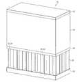
- FIG. 1Ais a perspective view of one embodiment of an armored radome according to the teachings of the present disclosure that is configured over the opening of an antenna;
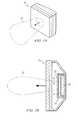
- FIG. 1Bis a cross-sectional, side elevational view of the radome and antenna of FIG. 1A ;
- FIG. 2is an enlarged, cross-sectional view of the various layers comprising the armored radome of FIGS. 1A and 1B ;
- FIGS. 3A and 3Bare graphs showing calculated insertion loss values of perpendicular and parallel components of electromagnetic radiation at various angles of incidence through the armored radome of FIG. 2 ;
- FIG. 3Cis the loss magnitude bar associated with FIGS. 3A and 3B .
- radomesthat are used to propagate electromagnetic radiation are often covered with radomes for protection from damage due to operation in uncontrolled environments.
- the radomesmay be positioned over an opening of the antenna array such that electro-magnetic radiation passes through freely while shielding its relatively delicate elements and associated electronics from the ambient environment.
- radomestypically include low radio-frequency (RF) loss materials, such as ceramics to not unduly affect the radiation pattern of the antenna.
- RFradio-frequency
- radomesshould have a generally robust structure to withstand impacts from bullets, shrapnel, and other similar forms of damaging projectiles. These characteristics may limit the type of materials from which radomes are made.
- FIGS. 1A and 1Bshow one embodiment of an armored radome 10 that may provide a solution to this problem and other problems.
- Armored radome 10is disposed over an antenna electronic unit 14 .
- Antenna electronic unit 14has a plurality of radiating elements 16 , associated electronics 18 , and an environmental radome 22 .
- Radiating elements 16are configured to transmit and/or receive electromagnetic radiation in the form of a radiation pattern 20 through armored radome 10 .
- Radiation pattern 20generally represents a relative electro-magnetic field intensity level at a locus of angular orientations relative to radiating elements 16 .
- An environmental radome 22may be included that is disposed between armored radome 10 and radiating elements 16 for protection from airborne debris, such as precipitation or dust.
- armored radome 10has a physically robust structure for protecting antenna electronic unit 14 from ballistic impact through its aperture 12 while not unduly affecting the radiation pattern 20 generated by antenna electronic unit 14 .
- antenna electronic unit 14is a microwave antenna array, such as an active electronically scanned array (AESA) in which its radiating elements 16 generate a radiation pattern 20 according to the combined radiation patterns of each of its radiating elements 16 .
- AESAactive electronically scanned array
- antenna electronic unit 14may be any device that is adapted to transmit or receive electromagnetic radiation at any desired frequency.
- armored radome 10is generally flat; however, armored radome 10 may have other shapes, such as a curved shape for enhanced scan angle deviation of antenna electronic unit 14 or for enhanced rigidity of radome's 10 structure.
- FIG. 2is an enlarged, cross-sectional, perspective view of a portion of armored radome 10 of FIG. 1 .
- Armored radome 10includes a ballistic-resistant layer 24 and a rigid layer 26 that are disposed adjacent each other through an intermediate layer 28 and bounded by backing layers 30 and 32 .
- Ballistic-resistant layer 24provides impact resistance for armored radome 10 while rigid layer 26 enhances the stiffness of ballistic-resistant layer 24 .
- Intermediate layer 28 and/or backing layers 30 and 32are optional and may be provided for impedance matching of radome 10 according to one or more desired operating frequency ranges.
- intermediate layer 28 , backing layer 30 , and backing layer 32may have a tensile strength that reduces cracking of ballistic-resistant layer 24 and/or rigid layer 26 due to impact by a projectile, such as a bullet or shrapnel.
- Ballistic-resistant layer 24may be formed of any structurally robust material having a relatively high dielectric constant, such as aluminum-oxide or silicon-nitride. Known ceramics including aluminum-oxide as a constituent material generally have relatively high dielectric constant values that may be greater than six. Aluminum-oxide is relatively impermeable to water, a characteristic that may enhance its resistance to changes in permittivity due to exposure to precipitation or other types of moisture that may collect on armored radome 10 . According to one particular embodiment, ballistic-resistant layer 24 may be approximately 1.0 inch thick to provide sufficient resistance from projectiles. Ballistic-resistant layer 24 , however, may have any thickness suitable for resisting impacts from projectiles while not unduly affecting radiation pattern 20 of antenna electronic unit 14 .
- Rigid layer 26is a composite structure having a honeycomb base material including a plurality of holes 40 that extend transversely relative to the surface of ballistic-resistant layer 24 .
- This structure of honeycomb base materialmay provide enhanced stiffness of armored radome 10 in a direction normal to its surface.
- holes 40are approximately 1 ⁇ 8 inch wide having a cross-sectional shape that is essentially hexagonal; however, other embodiments of honeycomb base material may have holes 40 of any suitable size with a circular, square, rectangular, or other suitable cross-sectional shape.
- syntactic foam material 42displaces air from holes 40 , which may reduce the armored radome's 10 susceptibility to changes in permittivity due to changes in ambient humidity or exposure to other forms of moisture.
- syntactic foam material 42is a closed-cell matrix including a plurality of microspheres that are bonded together with a suitable bonding agent, such as polyamide, polyethylenimine, or acrylate. Syntactic foam materials 42 of this type may enhance the relative stiffness of rigid layer 26 while maintaining a dielectric constant relatively close to that of air.
- the thicknesses and constituent materials forming the ballistic-resistant layer 24 , rigid layer 26 , intermediate layer 28 , backing layer 30 , and backing layer 32may be selected for a desired frequency band of operation. That is, the insertion loss and dielectric constant exhibited by each layer may be tailored by adjusting its thickness or constituent material such that armored radome 10 exhibits an overall loss tangent and impedance that is acceptable within the desired frequency range. In one example, the radome's resistance to a particular type of ballistic threat, such as shrapnel generated from a grenade blast, may be improved by increasing the relative thickness of rigid layer 26 .
- This incremental increase in thicknessmay cause the overall loss tangent of armored radome 10 to exceed acceptable limits at a particular frequency range.
- the thickness or composition of ballistic-resistant layer 24therefore, may be decreased to maintain the overall loss tangent of armored radome 10 within acceptable limits.
- Intermediate layer 28 , backing layer 30 , and/or backing layer 32may be made of a material having an intrinsic dielectric constant that is relatively less than the material from which ballistic-resistant layer 24 is formed for impedance matching armored radome 10 to its associated antenna electronic unit 14 .
- a particular ballistic-resistant layer 24 formed of a ceramic material including aluminum-oxidemay have a dielectric constant greater than six.
- intermediate layer 28 , backing layer 30 , and backing layer 32may be made of a material, such as cyanate ester/quartz having a dielectric constant that is less than approximately three.
- the thickness of intermediate layer 28 , backing layer 30 , and/or backing layer 30may be chosen to achieve an overall impedance of armored radome 10 matching that of its associated antenna electronic unit 14 .
- armored radome 10is designed for operation within the Ka-band, which may include frequencies in the range of approximately 32 to 37 Giga-Hertz.
- ballistic-resistant layer 24may be formed of a 1.0 inch thick layer of ceramic including aluminum-oxide as a base material
- rigid layer 26may be formed of a 0.25 inch thick layer of honeycomb base material made of cellulose and filled with syntactic foam material 42
- intermediate layer 28 , backing layer 30 , and backing layer 32may include a cyanate ester/quartz material that are 0.05 inches, 0.10 inches, and 0.05 inches thick, respectively.
- FIGS. 3A , 3 B, and 3 Care graphs showing calculated insertion loss values of electromagnetic radiation at various angles of incidence through a particular armored radome 10 constructed according to the previously described characteristics.
- FIG. 3Ashows an expected loss tangent of electromagnetic radiation perpendicular to armored radome 10
- FIG. 3Bshows an expected loss tangent parallel to the surface of armored radome 10
- FIG. 3Cis a linear chart that relates the various shading levels to their associated loss tangent values.
- the particular armored radome 10exhibits relatively little attenuation of electromagnetic radiation within the Ka-band of operation.
- armored radome 10may be integrated or separated.
- backing layers 30 and 32may each include multiple layers of differing types of material that may be combined together or may include one or more coatings of a suitable material that are applied prior to assembly on armored radome 10 .
- the operations of armored radome 10may be performed by more, fewer, or other components.
- environmental radome 22is included for additional protection of antenna electronic unit 14 ; however, environmental radome 22 may be omitted if this additional protection is not needed or desired.
Landscapes
- Details Of Aerials (AREA)
Abstract
Description
Claims (6)
Priority Applications (1)
| Application Number | Priority Date | Filing Date | Title |
|---|---|---|---|
| US12/258,209US8054239B2 (en) | 2008-10-24 | 2008-10-24 | Honeycomb-backed armored radome |
Applications Claiming Priority (1)
| Application Number | Priority Date | Filing Date | Title |
|---|---|---|---|
| US12/258,209US8054239B2 (en) | 2008-10-24 | 2008-10-24 | Honeycomb-backed armored radome |
Publications (2)
| Publication Number | Publication Date |
|---|---|
| US20100103072A1 US20100103072A1 (en) | 2010-04-29 |
| US8054239B2true US8054239B2 (en) | 2011-11-08 |
Family
ID=42116984
Family Applications (1)
| Application Number | Title | Priority Date | Filing Date |
|---|---|---|---|
| US12/258,209Active2029-10-24US8054239B2 (en) | 2008-10-24 | 2008-10-24 | Honeycomb-backed armored radome |
Country Status (1)
| Country | Link |
|---|---|
| US (1) | US8054239B2 (en) |
Cited By (9)
| Publication number | Priority date | Publication date | Assignee | Title |
|---|---|---|---|---|
| US20100295717A1 (en)* | 2008-01-29 | 2010-11-25 | Rourk Christopher J | Weapon detection and elimination system |
| US9116222B1 (en)* | 2010-11-18 | 2015-08-25 | Raytheon Company | Modular architecture for scalable phased array radars |
| US9236652B2 (en) | 2012-08-21 | 2016-01-12 | Raytheon Company | Broadband array antenna enhancement with spatially engineered dielectrics |
| US10153547B2 (en) | 2015-07-15 | 2018-12-11 | Raytheon Company | Armored radome |
| US10290935B2 (en) | 2016-06-27 | 2019-05-14 | Atc Materials Inc. | Low loss tri-band protective armor radome |
| CN111146583A (en)* | 2020-01-20 | 2020-05-12 | Oppo广东移动通信有限公司 | Antenna assembly and electronic equipment |
| CN111146582A (en)* | 2020-01-20 | 2020-05-12 | Oppo广东移动通信有限公司 | Antenna assembly and electronic equipment |
| RU2722559C2 (en)* | 2017-10-26 | 2020-06-01 | Общество с ограниченной ответственностью "Специальное Конструкторско-Технологическое Бюро "Пластик" | Structure of broad-band radioparent radome and method of its manufacture |
| US10693223B1 (en) | 2016-06-27 | 2020-06-23 | Atc Materials Inc. | Low loss tri-band protective armor radome |
Families Citing this family (8)
| Publication number | Priority date | Publication date | Assignee | Title |
|---|---|---|---|---|
| EP2571756B1 (en)* | 2010-05-17 | 2018-05-16 | Pepperl+Fuchs Gmbh | Radome |
| EP2747202A1 (en)* | 2012-12-18 | 2014-06-25 | EADS Deutschland GmbH | Radome wall |
| EP2811574B1 (en)* | 2013-06-03 | 2018-08-22 | Alcatel- Lucent Shanghai Bell Co., Ltd | Rigid radome for a concave reflector antenna |
| US11121447B2 (en)* | 2017-09-27 | 2021-09-14 | Apple Inc. | Dielectric covers for antennas |
| ES2951209T3 (en)* | 2018-01-10 | 2023-10-18 | Zanini Auto Grup Sa | Radome for vehicles |
| WO2020065714A1 (en)* | 2018-09-25 | 2020-04-02 | 三菱電機株式会社 | Radar device |
| WO2020147960A1 (en)* | 2019-01-18 | 2020-07-23 | Telefonaktiebolaget Lm Ericsson (Publ) | Combined antenna and radome arrangement |
| FR3099132B1 (en)* | 2019-07-26 | 2022-01-28 | Mbda France | HOOD FOR A VEHICLE, IN PARTICULAR FOR A SUPERSONIC OR HYPERSONIC VEHICLE |
Citations (20)
| Publication number | Priority date | Publication date | Assignee | Title |
|---|---|---|---|---|
| US2854374A (en) | 1953-06-09 | 1958-09-30 | Philips Corp | Method of killing insects using chlorophenyl-n,n-dimethylcarbamates |
| DE1107299B (en) | 1953-08-03 | 1961-05-25 | Edward Bellamy Mcmillan | Dielectric wall permeable to electromagnetic waves |
| US3780374A (en) | 1971-03-11 | 1973-12-18 | Sumitomo Electric Industries | Radome with matching layers |
| US4358772A (en) | 1980-04-30 | 1982-11-09 | Hughes Aircraft Company | Ceramic broadband radome |
| US4613540A (en) | 1984-10-09 | 1986-09-23 | Rogers Corporation | Window for broad bandwidth electromagnetic signal transmission, and method of construction thereof |
| US4783666A (en)* | 1987-05-21 | 1988-11-08 | General Electric Company | Protective shield for an antenna array |
| US4797683A (en)* | 1986-10-01 | 1989-01-10 | United Technologies Corporation | Multi-spectral radome |
| US4868040A (en) | 1988-10-20 | 1989-09-19 | Canadian Patents & Development Limited | Antiballistic composite armor |
| US5182155A (en)* | 1991-04-15 | 1993-01-26 | Itt Corporation | Radome structure providing high ballistic protection with low signal loss |
| US5408244A (en) | 1991-01-14 | 1995-04-18 | Norton Company | Radome wall design having broadband and mm-wave characteristics |
| GB2336807A (en) | 1998-04-27 | 1999-11-03 | David Adie | Ceramic sandwich material for ballistic protection |
| US6107976A (en)* | 1999-03-25 | 2000-08-22 | Bradley B. Teel | Hybrid core sandwich radome |
| US20020113168A1 (en)* | 2000-08-03 | 2002-08-22 | Rukavina Thomas G. | Switchable electrochromic devices for use in aircraft transparency windows |
| DE10257370B3 (en) | 2002-12-04 | 2004-06-17 | Fuß, Torsten, Dr. | Reflection-optimized antenna cladding for radio antenna operated in microwave frequency range using multi-layer dielectric cross-sectional structure |
| US6767606B2 (en)* | 2002-08-29 | 2004-07-27 | The Boeing Company | Vented cell structure and fabrication method |
| US20040246195A1 (en) | 2003-06-09 | 2004-12-09 | Mitsubishi Denki Kabushiki Kaisha | Radome |
| WO2006011133A1 (en) | 2004-07-25 | 2006-02-02 | Anafa-Electromagnetic Solutions Ltd. | Ballistic protective radome |
| EP1710218A1 (en) | 2005-04-06 | 2006-10-11 | Michael Cohen | Silicon nitride compositions |
| EP1796210A1 (en) | 2005-12-08 | 2007-06-13 | Raython Company | Broadband ballistic resistant radome |
| US20090286040A1 (en)* | 2008-05-13 | 2009-11-19 | The Boeing Company | Impact Resistant Core |
- 2008
- 2008-10-24USUS12/258,209patent/US8054239B2/enactiveActive
Patent Citations (22)
| Publication number | Priority date | Publication date | Assignee | Title |
|---|---|---|---|---|
| US2854374A (en) | 1953-06-09 | 1958-09-30 | Philips Corp | Method of killing insects using chlorophenyl-n,n-dimethylcarbamates |
| DE1107299B (en) | 1953-08-03 | 1961-05-25 | Edward Bellamy Mcmillan | Dielectric wall permeable to electromagnetic waves |
| US3780374A (en) | 1971-03-11 | 1973-12-18 | Sumitomo Electric Industries | Radome with matching layers |
| US4358772A (en) | 1980-04-30 | 1982-11-09 | Hughes Aircraft Company | Ceramic broadband radome |
| US4613540A (en) | 1984-10-09 | 1986-09-23 | Rogers Corporation | Window for broad bandwidth electromagnetic signal transmission, and method of construction thereof |
| US4797683A (en)* | 1986-10-01 | 1989-01-10 | United Technologies Corporation | Multi-spectral radome |
| US4783666A (en)* | 1987-05-21 | 1988-11-08 | General Electric Company | Protective shield for an antenna array |
| US4868040A (en) | 1988-10-20 | 1989-09-19 | Canadian Patents & Development Limited | Antiballistic composite armor |
| US5408244A (en) | 1991-01-14 | 1995-04-18 | Norton Company | Radome wall design having broadband and mm-wave characteristics |
| US5182155A (en)* | 1991-04-15 | 1993-01-26 | Itt Corporation | Radome structure providing high ballistic protection with low signal loss |
| GB2336807A (en) | 1998-04-27 | 1999-11-03 | David Adie | Ceramic sandwich material for ballistic protection |
| US6107976A (en)* | 1999-03-25 | 2000-08-22 | Bradley B. Teel | Hybrid core sandwich radome |
| US20020113168A1 (en)* | 2000-08-03 | 2002-08-22 | Rukavina Thomas G. | Switchable electrochromic devices for use in aircraft transparency windows |
| US6767606B2 (en)* | 2002-08-29 | 2004-07-27 | The Boeing Company | Vented cell structure and fabrication method |
| DE10257370B3 (en) | 2002-12-04 | 2004-06-17 | Fuß, Torsten, Dr. | Reflection-optimized antenna cladding for radio antenna operated in microwave frequency range using multi-layer dielectric cross-sectional structure |
| US20040246195A1 (en) | 2003-06-09 | 2004-12-09 | Mitsubishi Denki Kabushiki Kaisha | Radome |
| WO2006011133A1 (en) | 2004-07-25 | 2006-02-02 | Anafa-Electromagnetic Solutions Ltd. | Ballistic protective radome |
| US7688278B2 (en)* | 2004-07-25 | 2010-03-30 | Avraham Frenkel | Ballistic protective radome |
| EP1710218A1 (en) | 2005-04-06 | 2006-10-11 | Michael Cohen | Silicon nitride compositions |
| EP1796210A1 (en) | 2005-12-08 | 2007-06-13 | Raython Company | Broadband ballistic resistant radome |
| US7817099B2 (en)* | 2005-12-08 | 2010-10-19 | Raytheon Company | Broadband ballistic resistant radome |
| US20090286040A1 (en)* | 2008-05-13 | 2009-11-19 | The Boeing Company | Impact Resistant Core |
Non-Patent Citations (4)
| Title |
|---|
| European Search Report for Application No. 06256063.6-2220, 9 pages, Mar. 9, 2007. |
| European Search Report for Application No. 09150813.5-2220/2081252, 8 pages, Dec. 22, 2009. |
| Wu, et al.; U.S. Appl. No. 11/297,999; entitled "Broadband Ballistic Resistant Radome";(Spec-22 pages and Drawings-7 pages), Dec. 8, 2005. |
| Wu, et al.;U.S. Appl. No. 12/016,867; entitled "Broadband Ballistic Resistant Radome"; (Spec-30 pages and Drawings-10 pages), Jan. 18, 2008. |
Cited By (11)
| Publication number | Priority date | Publication date | Assignee | Title |
|---|---|---|---|---|
| US20100295717A1 (en)* | 2008-01-29 | 2010-11-25 | Rourk Christopher J | Weapon detection and elimination system |
| US9116222B1 (en)* | 2010-11-18 | 2015-08-25 | Raytheon Company | Modular architecture for scalable phased array radars |
| US9236652B2 (en) | 2012-08-21 | 2016-01-12 | Raytheon Company | Broadband array antenna enhancement with spatially engineered dielectrics |
| US10153547B2 (en) | 2015-07-15 | 2018-12-11 | Raytheon Company | Armored radome |
| US10290935B2 (en) | 2016-06-27 | 2019-05-14 | Atc Materials Inc. | Low loss tri-band protective armor radome |
| US10693223B1 (en) | 2016-06-27 | 2020-06-23 | Atc Materials Inc. | Low loss tri-band protective armor radome |
| RU2722559C2 (en)* | 2017-10-26 | 2020-06-01 | Общество с ограниченной ответственностью "Специальное Конструкторско-Технологическое Бюро "Пластик" | Structure of broad-band radioparent radome and method of its manufacture |
| CN111146583A (en)* | 2020-01-20 | 2020-05-12 | Oppo广东移动通信有限公司 | Antenna assembly and electronic equipment |
| CN111146582A (en)* | 2020-01-20 | 2020-05-12 | Oppo广东移动通信有限公司 | Antenna assembly and electronic equipment |
| CN111146582B (en)* | 2020-01-20 | 2021-10-08 | Oppo广东移动通信有限公司 | Antenna components and electronic equipment |
| CN111146583B (en)* | 2020-01-20 | 2021-10-08 | Oppo广东移动通信有限公司 | Antenna assembly and electronic equipment |
Also Published As
| Publication number | Publication date |
|---|---|
| US20100103072A1 (en) | 2010-04-29 |
Similar Documents
| Publication | Publication Date | Title |
|---|---|---|
| US8054239B2 (en) | Honeycomb-backed armored radome | |
| US7817099B2 (en) | Broadband ballistic resistant radome | |
| US8368610B2 (en) | Shaped ballistic radome | |
| US5182155A (en) | Radome structure providing high ballistic protection with low signal loss | |
| CN111418113B (en) | Radome structure, protected radioactive active system and methods of use thereof | |
| US8497812B2 (en) | Composite radome and radiator structure | |
| US8599095B2 (en) | Broadband ballistic resistant radome | |
| US9385423B2 (en) | Protective ballistic radome for a satellite antenna | |
| JP2010506453A5 (en) | ||
| US11095025B2 (en) | Radome wall for communication applications | |
| US8854269B2 (en) | Compact embedded antenna | |
| EP0742095B1 (en) | Composite material structure able to absorb and dissipate incident electromagnetic radiation power, in particular for air, water and land craft and for fixed ground installations | |
| EP3619041A1 (en) | Aircraft radomes with broadband transparency | |
| US8151686B2 (en) | Armor module | |
| US7817100B2 (en) | Ballistic resistant antenna assembly | |
| US11646486B2 (en) | Antenna device | |
| US7671801B2 (en) | Armor for an electronically scanned array | |
| KR102008505B1 (en) | Flexible amor and manufacturing method thereof | |
| JP2011041130A (en) | Radome and flying object | |
| US20140060301A1 (en) | Advancement to the Effectiveness of Body Armor | |
| KR102558314B1 (en) | Composite Panel having an Electromagnetic Wave Absorption Function and Structure including the Same | |
| RU2400882C1 (en) | Radar antenna with decreased effective scattering area | |
| RU178356U1 (en) | COURSE LANDING RADIO BEACON | |
| KR20230082285A (en) | Microwave absorbing form based sandwich composite with metallic lightning protection layer | |
| WO2015084207A1 (en) | Radio-transparent armor |
Legal Events
| Date | Code | Title | Description |
|---|---|---|---|
| AS | Assignment | Owner name:RAYTHEON COMPANY,MASSACHUSETTS Free format text:ASSIGNMENT OF ASSIGNORS INTEREST;ASSIGNORS:WU, KUANG-YUH (NMI);PRUETT, JAMES A.;WAHLQUIST, GARY F.;AND OTHERS;SIGNING DATES FROM 20081212 TO 20081229;REEL/FRAME:022091/0715 Owner name:RAYTHEON COMPANY, MASSACHUSETTS Free format text:ASSIGNMENT OF ASSIGNORS INTEREST;ASSIGNORS:WU, KUANG-YUH (NMI);PRUETT, JAMES A.;WAHLQUIST, GARY F.;AND OTHERS;SIGNING DATES FROM 20081212 TO 20081229;REEL/FRAME:022091/0715 | |
| AS | Assignment | Owner name:RAYTHEON COMPANY,MASSACHUSETTS Free format text:ASSIGNMENT OF ASSIGNORS INTEREST;ASSIGNORS:WU, KUANG-YUH (NMI);PRUETT, JAMES A.;WAHLQUIST, GARY F.;AND OTHERS;SIGNING DATES FROM 20100316 TO 20100319;REEL/FRAME:024187/0339 Owner name:RAYTHEON COMPANY, MASSACHUSETTS Free format text:ASSIGNMENT OF ASSIGNORS INTEREST;ASSIGNORS:WU, KUANG-YUH (NMI);PRUETT, JAMES A.;WAHLQUIST, GARY F.;AND OTHERS;SIGNING DATES FROM 20100316 TO 20100319;REEL/FRAME:024187/0339 | |
| FEPP | Fee payment procedure | Free format text:PAYOR NUMBER ASSIGNED (ORIGINAL EVENT CODE: ASPN); ENTITY STATUS OF PATENT OWNER: LARGE ENTITY | |
| STCF | Information on status: patent grant | Free format text:PATENTED CASE | |
| FPAY | Fee payment | Year of fee payment:4 | |
| MAFP | Maintenance fee payment | Free format text:PAYMENT OF MAINTENANCE FEE, 8TH YEAR, LARGE ENTITY (ORIGINAL EVENT CODE: M1552); ENTITY STATUS OF PATENT OWNER: LARGE ENTITY Year of fee payment:8 | |
| MAFP | Maintenance fee payment | Free format text:PAYMENT OF MAINTENANCE FEE, 12TH YEAR, LARGE ENTITY (ORIGINAL EVENT CODE: M1553); ENTITY STATUS OF PATENT OWNER: LARGE ENTITY Year of fee payment:12 |