US8054049B1 - Using battery orientation to control mode of operation - Google Patents
Using battery orientation to control mode of operationDownload PDFInfo
- Publication number
- US8054049B1 US8054049B1US11/847,924US84792407AUS8054049B1US 8054049 B1US8054049 B1US 8054049B1US 84792407 AUS84792407 AUS 84792407AUS 8054049 B1US8054049 B1US 8054049B1
- Authority
- US
- United States
- Prior art keywords
- battery
- polarity
- mode
- control signal
- orientation
- Prior art date
- Legal status (The legal status is an assumption and is not a legal conclusion. Google has not performed a legal analysis and makes no representation as to the accuracy of the status listed.)
- Active, expires
Links
Images


Classifications
- H—ELECTRICITY
- H02—GENERATION; CONVERSION OR DISTRIBUTION OF ELECTRIC POWER
- H02J—CIRCUIT ARRANGEMENTS OR SYSTEMS FOR SUPPLYING OR DISTRIBUTING ELECTRIC POWER; SYSTEMS FOR STORING ELECTRIC ENERGY
- H02J7/00—Circuit arrangements for charging or depolarising batteries or for supplying loads from batteries
- H02J7/0029—Circuit arrangements for charging or depolarising batteries or for supplying loads from batteries with safety or protection devices or circuits
- H02J7/0034—Circuit arrangements for charging or depolarising batteries or for supplying loads from batteries with safety or protection devices or circuits using reverse polarity correcting or protecting circuits
- H—ELECTRICITY
- H02—GENERATION; CONVERSION OR DISTRIBUTION OF ELECTRIC POWER
- H02J—CIRCUIT ARRANGEMENTS OR SYSTEMS FOR SUPPLYING OR DISTRIBUTING ELECTRIC POWER; SYSTEMS FOR STORING ELECTRIC ENERGY
- H02J7/00—Circuit arrangements for charging or depolarising batteries or for supplying loads from batteries
- H02J7/0029—Circuit arrangements for charging or depolarising batteries or for supplying loads from batteries with safety or protection devices or circuits
- H02J7/0036—Circuit arrangements for charging or depolarising batteries or for supplying loads from batteries with safety or protection devices or circuits using connection detecting circuits
- H—ELECTRICITY
- H02—GENERATION; CONVERSION OR DISTRIBUTION OF ELECTRIC POWER
- H02J—CIRCUIT ARRANGEMENTS OR SYSTEMS FOR SUPPLYING OR DISTRIBUTING ELECTRIC POWER; SYSTEMS FOR STORING ELECTRIC ENERGY
- H02J7/00—Circuit arrangements for charging or depolarising batteries or for supplying loads from batteries
- H02J7/0063—Circuit arrangements for charging or depolarising batteries or for supplying loads from batteries with circuits adapted for supplying loads from the battery
- G—PHYSICS
- G01—MEASURING; TESTING
- G01R—MEASURING ELECTRIC VARIABLES; MEASURING MAGNETIC VARIABLES
- G01R19/00—Arrangements for measuring currents or voltages or for indicating presence or sign thereof
- G01R19/14—Indicating direction of current; Indicating polarity of voltage
Definitions
- An exemplary embodiment of the present inventionis directed toward battery-powered devices, and more specifically for controlling the operating mode of a battery-powered device.
- Battery polarity identification circuitsare well known.
- U.S. Pat. No. 5,838,143is directed toward an automatic battery polarity identification circuit having a first electroplate and a second electroplate adapted for receiving two opposite ends of a battery.
- the circuitfurther comprises a capacitor having a first end and a second end, and at least one relay, each of the at least one relay having a coil, the coil having a first end connected to the first end of the capacitor and a second end, a second fixed contact and a third fixed contact connected between the first electroplate and the second end of the coil, the first fixed contact and a fourth fixed contact connected to the second electrode.
- An exemplary embodiment of the present inventionis generally directed toward reconfiguration of a device, such as a battery-powered device, based on the manner in which a battery(s) is installed.
- the electrical contacts in the battery compartment of the devicewill permit the battery to be inserted with the “+” pole of the battery against either one of the two contacts, with the “ ⁇ ” pole of the battery positioned against the other contact.
- a polarity-sensing circuitdetects the battery's orientation. If a first orientation is detected, i.e., where the “+” pole of the battery is touching Contact A and “ ⁇ ” pole of the battery is touching Contact B, the polarity-sensing circuit mode-of-operation 1 will be selected.
- polarity-sensing circuit mode-of-operation 2will be selected.
- a bridge rectifier, downstream from the polarity sensor,can ensure that the other circuits in the device continue to receive power that is polarized correctly regardless of battery orientation.
- the polarity detection mechanism and bridge rectifiercan be implemented with no moving parts, rather than an electro-mechanical switch as the user interface for selecting between available modes-of-operation.
- Different constructs of the deviceallow different types of polarity detectors to be used, along with different configurations of polarity detectors with, for example, the ability to activate a low battery indicator upon the inability to, for example, detect current.
- Still further exemplary embodiments of the inventionrelate to the ability to switch a device, illustratively a telephone handset between a first mode of operation (e.g., a “press to amplify” mode) and a second mode of operation (e.g., a “press to talk” mode) based on battery orientation.
- a first mode of operatione.g., a “press to amplify” mode
- a second mode of operatione.g., a “press to talk” mode
- Exemplary embodiments of the inventionalso relate to the ability to switch a device, such as a toy, or in general any device, between a first mode of operation and a second mode of operation based on battery orientation.
- Additional aspects of the inventionrelate to the ability to control the mode of operation of a portion of a device based on the polarity sensing circuit(s) while not affecting the mode of operation of another portion of the device.
- FIG. 1illustrates an exemplary embodiment of a battery orientation operational control circuit according to this invention
- FIG. 2illustrates an alternative configuration of the battery orientation operational control circuit of FIG. 1 ;
- FIG. 3illustrates a second exemplary embodiment of a battery orientation operational control circuit according to this invention
- FIG. 4illustrates a third exemplary embodiment of a battery orientation operational control circuit according to this invention
- FIG. 5illustrates a fourth exemplary embodiment of a battery orientation operational control circuit according to this invention
- FIG. 6is a flowchart outlining an exemplary method for operating a battery orientation operational control circuit according to this invention.
- FIG. 7is a flowchart illustrating an alternative exemplary embodiment for operating a battery orientation operational control circuit according to this invention.
- FIG. 8is a flowchart illustrating another method for operating a battery orientation operational control circuit according to this invention.
- the exemplary embodiments of this inventionwill be described in relation to a battery orientation operational control circuit and associated components. However, it should be appreciated that in general, the systems and methods of this invention work well in a plurality of environments, including AC, DC, and can be extended to include one or more batteries. In multi-battery configurations, the batteries themselves may be in series, in parallel, or a combination of the two.
- modulecan refer to any known or later developed hardware, software, firmware, or combination thereof that is capable of performing the functionality associated with that element.
- the terms determine, calculate and compute, and variations thereof, as used hereinare used interchangeably and include any type of methodology, process, mathematical operation or technique.
- the term “a” or “an” entityrefers to one or more of that entity.
- the terms “a” (or “an”), “one or more” and “at least one”can be used interchangeably herein.
- the terms “comprising”, “including” and “having”can be used interchangeably.
- each of the expressions “at least one of A, B and C”, “at least one of A, B, or C”, “one or more of A, B, and C”, “one or more of A, B, or C” and “A, B, and/or C”means A alone, B alone, C alone, A and B together, A and C together, B and C together, or A, B and C together.
- FIGS. 1 and 2illustrate an exemplary embodiment of a battery orientation operational control circuit 100 according to this invention.
- the battery orientation operational control circuit 100comprises a battery 110 , a polarity detector 120 , a bridge rectifier 130 and a device 140 .
- the battery 100is oriented in a first direction.
- the polarity detector 120detects the battery orientation and, with the cooperation of the polarity detector 120 , outputs a polarity detection signal.
- the polarity detection circuit 120outputs a polarity detection signal indicating the battery is in “Orientation 1 .” This polarity detection signal can be used to control the operational mode of the device 140 based on the battery's orientation.
- the battery 110is in a second orientation. Similar to the operation of FIG. 1 , the polarity detector 120 detects the orientation of the battery 110 and outputs a polarity detection signal, which in this case indicates the operational mode should be in accordance with “Orientation 2 ” based on the change in polarity of the battery 110 .
- FIG. 3illustrates another alternative embodiment of a battery orientation operational control circuit 300 .
- the battery orientation operational control circuit 300comprises a battery 310 , a polarity detector 320 , a bridge rectifier 330 , a switch 340 , polarity detection signals 350 and device 360 .
- the battery 310is oriented in a first position, which corresponds to Operating Mode 1 . More specifically, the polarity detector 320 detects the battery orientation and outputs a polarity detection signal which is forwarded to switch 340 . The polarity detection signal controls the switch 340 to select between Operating Mode 1 and Operating Mode 2 . Thus, since the battery 310 is in a first orientation, the polarity detection signal switches the switch 340 to position “ 1 ” which subsequently outputs or selects Operating Mode 1 of, for example, device 360 . It should be appreciated however, that while the selection of operational mode is discussed in relation to, for example, device 360 , the operating mode control signal can be used to control any one or more devices (not shown) and is not limited to device 360 .
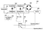
- FIG. 4illustrates another exemplary embodiment of a battery orientation operational control circuit 400 .
- the battery orientation operational control circuit 400comprises a battery 410 , a first polarity detection circuit including current detector 420 , diode 430 and resistor 440 , a second polarity detection circuit including resistor 450 , diode 460 and current detector 470 , bridge rectifier 480 , switch 485 and device 490 .
- the battery orientation operational control circuit 400can also optionally include a low battery indicator module 495 .
- currentis detected at one of the current detectors 420 and 470 .
- one of the current detectors 420 and 470outputs a polarity detection signal, 402 and 404 , respectively.
- the current detector 420outputs the polarity detection signal 402 to switch 485 .
- the polarity detection signal 402enables the switch 485 to select Operating Mode 1 which corresponds to a first operational mode of device 490 .
- polarity detection signal 404is output to switch 485 .
- polarity detection signal 404switches switch 485 to select Operating Mode 2 which corresponds to a second operational mode of device 490 .
- the battery orientation operational control circuit 400can also include a low battery indicator module 495 .
- the low battery indicator module 495can be connected to outputs of the current detectors 420 and 47 . In the event that neither current detector is producing an output, the low battery indicator module 495 can provide an indication that the battery 410 is low on power.
- FIG. 5illustrates an alternative exemplary embodiment of a battery orientation operational control circuit 500 .
- the battery orientation operational control circuit 500comprises a battery 510 , a current detector 520 , one or more resistors 530 (which, similar to the other embodiments, can optionally be placed on one or more sides of the diode), diode 535 , bridge rectifier 540 , switch 550 and device 560 .
- a determinationis made whether current is detected at the current detector 520 .
- current detector 520In this particular configuration, with the battery 510 oriented in a first direction, current will not be detected at current detector 520 . However, when the battery orientation is switched, current will be detected at current detector 520 and a corresponding polarity detection signal 502 output to switch 550 .
- the polarity detection signal 502controls the switch such that if current is detected, switch 550 is in an open position (which may correspond to Operating Mode 1 ) and if no current is detected, switch 550 switches to a closed position, which for example, corresponds to Operating Mode 2 of device 560 .
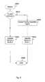
- FIG. 6illustrates an exemplary mode of operation of a battery operational control circuit.
- controlbegins in step S 600 and continues to step S 610 .
- step S 610battery orientation is detected.
- step S 620a polarity detection signal is output.
- step S 630a determination is made which operational mode the battery orientation operational control circuit should operate in. If a first polarity detection signal is detected, battery orientation operational control circuit operates in mode 1 (step S 650 ) with control continuing step S 660 where the control sequence ends.
- step S 640the battery orientation operational control circuit operates in mode 2 (step S 640 ) with control continuing to step S 660 where the control sequence ends.
- FIG. 7outlines a second exemplary method of operation of a battery orientation operational control circuit.
- controlbegins at step S 700 and continues to step S 710 .
- step S 710current at one of a plurality of current detectors is detected.
- step S 720a polarity detection signal is output from the current detector where the current is detected.
- step S 730a determination is made whether current has been detected at a first current detector. If current has been detected, control continues to step S 770 where the control signal places the device into a first mode of operation. However, if no current is detected, control continues to step S 740 where a determination is made whether current is detected at the second current detector. If current is detected at the second current detector, control continues to step S 760 where the control signal places the device in a second mode of operation, with control continuing to step S 780 .
- step 750can activate a low battery indicator with control continuing to step S 780 where the control sequence ends.
- the detection of current in many devicesis not a simple yes/no test of whether an electrical current is present, but is instead a determination of whether the current in the circuit exceeds a threshold value.
- the detection of currentis intended to include cases in which there is no current as well as cases in which the current must exceed a non-zero value in order to be regarded as detected.
- FIG. 8outlines another exemplary embodiment of controlling a battery orientation operational control circuit according to this invention.
- Controlbegins at S 800 and continues to step S 810 .
- step S 810a determination is made whether current is detected. If current is not detected, control continues to step S 820 where the device operates in a second mode of operation with control continue to step S 850 where the control sequence ends.
- step S 830a polarity detection signal is output.
- this polarity detection signalis used to place the device in a first mode of operation with control continuing to step S 850 where the control sequence ends.
- the present inventionin various embodiments, includes components, methods, processes, systems and/or apparatus substantially as depicted and described herein, including various embodiments, subcombinations and subsets thereof. Those of skill in the art will understand how to make and use the present invention after understanding the present disclosure.
- the present inventionin various embodiments, includes providing devices and processes in the absence of items not depicted and/or described herein or in various embodiments hereof, including in the absence of such items as may have been used in previous devices or processes, e.g., for improving performance, achieving ease and ⁇ or reducing cost of implementation.
Landscapes
- Engineering & Computer Science (AREA)
- Power Engineering (AREA)
- Charge And Discharge Circuits For Batteries Or The Like (AREA)
Abstract
Description
Claims (20)
Priority Applications (1)
| Application Number | Priority Date | Filing Date | Title |
|---|---|---|---|
| US11/847,924US8054049B1 (en) | 2007-08-30 | 2007-08-30 | Using battery orientation to control mode of operation |
Applications Claiming Priority (1)
| Application Number | Priority Date | Filing Date | Title |
|---|---|---|---|
| US11/847,924US8054049B1 (en) | 2007-08-30 | 2007-08-30 | Using battery orientation to control mode of operation |
Publications (1)
| Publication Number | Publication Date |
|---|---|
| US8054049B1true US8054049B1 (en) | 2011-11-08 |
Family
ID=44882505
Family Applications (1)
| Application Number | Title | Priority Date | Filing Date |
|---|---|---|---|
| US11/847,924Active2028-06-13US8054049B1 (en) | 2007-08-30 | 2007-08-30 | Using battery orientation to control mode of operation |
Country Status (1)
| Country | Link |
|---|---|
| US (1) | US8054049B1 (en) |
Cited By (10)
| Publication number | Priority date | Publication date | Assignee | Title |
|---|---|---|---|---|
| US20120326776A1 (en)* | 2011-06-25 | 2012-12-27 | Jlj, Inc. | Battery polarity control system |
| WO2015002718A1 (en)* | 2013-07-01 | 2015-01-08 | Apple Inc. | Polarity sensing circuit |
| WO2015036437A1 (en)* | 2013-09-13 | 2015-03-19 | Tanktwo Oy | Batteries and battery systems for storing electrical energy |
| WO2015036438A1 (en)* | 2013-09-13 | 2015-03-19 | Tanktwo Oy | Electric energy storage and supply system |
| WO2015074689A1 (en)* | 2013-11-20 | 2015-05-28 | Siemens Aktiengesellschaft | A high voltage converter circuit equipped with a voltage monitoring device |
| US20160106424A1 (en)* | 2014-10-15 | 2016-04-21 | Ethicon Endo-Surgery, Inc. | Surgical instrument battery pack with voltage polling |
| WO2017173221A1 (en)* | 2016-03-31 | 2017-10-05 | Elitise Llc | Battery module with orientation detection for alternate operative states |
| US10229552B2 (en) | 2013-09-13 | 2019-03-12 | Tanktwo Oy | Methods and systems for delivering electric energy |
| US11026682B2 (en) | 2014-10-15 | 2021-06-08 | Cilag Gmbh International | Surgical instrument battery pack with voltage polling |
| US20210376617A1 (en)* | 2018-12-06 | 2021-12-02 | Fdk Corporation | Battery polarity determination circuit, charger, and electronic device |
Citations (19)
| Publication number | Priority date | Publication date | Assignee | Title |
|---|---|---|---|---|
| US2869717A (en)* | 1953-06-24 | 1959-01-20 | Mergenthaler Linotype Gmbh | Typographical composing machine |
| US3434034A (en)* | 1967-03-14 | 1969-03-18 | Hewlett Packard Co | Universal ac or dc to dc converter |
| US3700999A (en)* | 1972-01-11 | 1972-10-24 | Us Army | Automatic battery polarizing circuit |
| US3819951A (en)* | 1972-11-28 | 1974-06-25 | Microsystems Int Ltd | Polarity guard |
| US3860868A (en)* | 1973-09-26 | 1975-01-14 | Joseph S Lindell | Voltage polarity sensor indicator and director circuit device |
| US4027223A (en)* | 1976-07-06 | 1977-05-31 | Renz Frank G | Transceiver polarity protector |
| US4139880A (en)* | 1977-10-03 | 1979-02-13 | Motorola, Inc. | CMOS polarity reversal circuit |
| US4420786A (en)* | 1981-11-16 | 1983-12-13 | Motorola, Inc. | Polarity guard circuit |
| US4423456A (en)* | 1981-11-13 | 1983-12-27 | Medtronic, Inc. | Battery reversal protection |
| US4473757A (en)* | 1981-12-08 | 1984-09-25 | Intersil, Inc. | Circuit means for converting a bipolar input to a unipolar output |
| US5161879A (en)* | 1991-04-10 | 1992-11-10 | Mcdermott Kevin | Flashlight for covert applications |
| US5343138A (en)* | 1990-08-27 | 1994-08-30 | Harvey W. O'Conor | Battery discharging and charging |
| US5343135A (en)* | 1988-05-20 | 1994-08-30 | Matson Automotive Industries Pty Ltd | Voltage limiting and indicating device |
| US5623550A (en)* | 1995-03-08 | 1997-04-22 | Etymotic Research, Inc. | Battery power supply circuit which supplies correct power polarity irrespective of battery orientation |
| US6023418A (en)* | 1999-04-29 | 2000-02-08 | Cardiac Evaluation Center, Inc. | Low voltage polarity correcting DC to DC converter |
| JP2000138982A (en)* | 1998-10-30 | 2000-05-16 | Aiphone Co Ltd | Infrared remote controller |
| US20050269480A1 (en)* | 2003-10-23 | 2005-12-08 | Ford Timothy D | Multifunction multi-spectrum signalling device |
| US20060146724A1 (en)* | 2004-12-17 | 2006-07-06 | Motorola, Inc. | Method and system for multi-function push-to-activate |
| US20060173651A1 (en)* | 2003-07-16 | 2006-08-03 | Andrea Ferrari | System and method for the dimension checking of mechanical pieces |
- 2007
- 2007-08-30USUS11/847,924patent/US8054049B1/enactiveActive
Patent Citations (19)
| Publication number | Priority date | Publication date | Assignee | Title |
|---|---|---|---|---|
| US2869717A (en)* | 1953-06-24 | 1959-01-20 | Mergenthaler Linotype Gmbh | Typographical composing machine |
| US3434034A (en)* | 1967-03-14 | 1969-03-18 | Hewlett Packard Co | Universal ac or dc to dc converter |
| US3700999A (en)* | 1972-01-11 | 1972-10-24 | Us Army | Automatic battery polarizing circuit |
| US3819951A (en)* | 1972-11-28 | 1974-06-25 | Microsystems Int Ltd | Polarity guard |
| US3860868A (en)* | 1973-09-26 | 1975-01-14 | Joseph S Lindell | Voltage polarity sensor indicator and director circuit device |
| US4027223A (en)* | 1976-07-06 | 1977-05-31 | Renz Frank G | Transceiver polarity protector |
| US4139880A (en)* | 1977-10-03 | 1979-02-13 | Motorola, Inc. | CMOS polarity reversal circuit |
| US4423456A (en)* | 1981-11-13 | 1983-12-27 | Medtronic, Inc. | Battery reversal protection |
| US4420786A (en)* | 1981-11-16 | 1983-12-13 | Motorola, Inc. | Polarity guard circuit |
| US4473757A (en)* | 1981-12-08 | 1984-09-25 | Intersil, Inc. | Circuit means for converting a bipolar input to a unipolar output |
| US5343135A (en)* | 1988-05-20 | 1994-08-30 | Matson Automotive Industries Pty Ltd | Voltage limiting and indicating device |
| US5343138A (en)* | 1990-08-27 | 1994-08-30 | Harvey W. O'Conor | Battery discharging and charging |
| US5161879A (en)* | 1991-04-10 | 1992-11-10 | Mcdermott Kevin | Flashlight for covert applications |
| US5623550A (en)* | 1995-03-08 | 1997-04-22 | Etymotic Research, Inc. | Battery power supply circuit which supplies correct power polarity irrespective of battery orientation |
| JP2000138982A (en)* | 1998-10-30 | 2000-05-16 | Aiphone Co Ltd | Infrared remote controller |
| US6023418A (en)* | 1999-04-29 | 2000-02-08 | Cardiac Evaluation Center, Inc. | Low voltage polarity correcting DC to DC converter |
| US20060173651A1 (en)* | 2003-07-16 | 2006-08-03 | Andrea Ferrari | System and method for the dimension checking of mechanical pieces |
| US20050269480A1 (en)* | 2003-10-23 | 2005-12-08 | Ford Timothy D | Multifunction multi-spectrum signalling device |
| US20060146724A1 (en)* | 2004-12-17 | 2006-07-06 | Motorola, Inc. | Method and system for multi-function push-to-activate |
Cited By (25)
| Publication number | Priority date | Publication date | Assignee | Title |
|---|---|---|---|---|
| US20120326776A1 (en)* | 2011-06-25 | 2012-12-27 | Jlj, Inc. | Battery polarity control system |
| US8654549B2 (en)* | 2011-06-25 | 2014-02-18 | Jlj, Inc. | Battery polarity control system |
| WO2015002718A1 (en)* | 2013-07-01 | 2015-01-08 | Apple Inc. | Polarity sensing circuit |
| US9506955B2 (en) | 2013-07-01 | 2016-11-29 | Apple Inc. | Polarity sensing circuit |
| WO2015036437A1 (en)* | 2013-09-13 | 2015-03-19 | Tanktwo Oy | Batteries and battery systems for storing electrical energy |
| WO2015036438A1 (en)* | 2013-09-13 | 2015-03-19 | Tanktwo Oy | Electric energy storage and supply system |
| CN105722718A (en)* | 2013-09-13 | 2016-06-29 | 汤克图公司 | Batteries and battery systems for storing electrical energy |
| CN105722717A (en)* | 2013-09-13 | 2016-06-29 | 汤克图公司 | Electric energy storage and supply system |
| US9450220B2 (en) | 2013-09-13 | 2016-09-20 | Tanktwo Oy | Electric energy storage and supply system |
| US9806318B2 (en) | 2013-09-13 | 2017-10-31 | Tanktwo Oy | Batteries and battery systems for storing electrical energy |
| CN105722717B (en)* | 2013-09-13 | 2017-08-15 | 汤克图公司 | Power storage and supply system and the electric vehicle including the system |
| US10229552B2 (en) | 2013-09-13 | 2019-03-12 | Tanktwo Oy | Methods and systems for delivering electric energy |
| WO2015074689A1 (en)* | 2013-11-20 | 2015-05-28 | Siemens Aktiengesellschaft | A high voltage converter circuit equipped with a voltage monitoring device |
| US20160106424A1 (en)* | 2014-10-15 | 2016-04-21 | Ethicon Endo-Surgery, Inc. | Surgical instrument battery pack with voltage polling |
| US9974539B2 (en)* | 2014-10-15 | 2018-05-22 | Ethicon Llc | Surgical instrument battery pack with voltage polling |
| CN108370072A (en)* | 2014-10-15 | 2018-08-03 | 伊西康有限责任公司 | Surgical instruments battery pack with voltage poll |
| CN108601593A (en)* | 2014-10-15 | 2018-09-28 | 伊西康有限责任公司 | Surgical instruments battery pack with power specification emulation |
| US11026682B2 (en) | 2014-10-15 | 2021-06-08 | Cilag Gmbh International | Surgical instrument battery pack with voltage polling |
| CN108370072B (en)* | 2014-10-15 | 2021-09-03 | 伊西康有限责任公司 | Surgical instrument battery pack with voltage polling |
| US11517307B2 (en) | 2014-10-15 | 2022-12-06 | Cilag Gmbh International | Surgical instrument battery pack with voltage polling |
| US12193672B2 (en) | 2014-10-15 | 2025-01-14 | Cilag Gmbh International | Surgical instrument battery pack with voltage polling |
| US20190027791A1 (en)* | 2016-03-31 | 2019-01-24 | Elitise Llc | Battery module with orientation detection for alternate operative states |
| WO2017173221A1 (en)* | 2016-03-31 | 2017-10-05 | Elitise Llc | Battery module with orientation detection for alternate operative states |
| US20210376617A1 (en)* | 2018-12-06 | 2021-12-02 | Fdk Corporation | Battery polarity determination circuit, charger, and electronic device |
| US11936223B2 (en)* | 2018-12-06 | 2024-03-19 | Fdk Corporation | Battery polarity determination circuit, charger, and electronic device |
Similar Documents
| Publication | Publication Date | Title |
|---|---|---|
| US8054049B1 (en) | Using battery orientation to control mode of operation | |
| US9024646B2 (en) | Circuit for measuring insulation resistance | |
| US9118193B2 (en) | Bidirectional wireless charging/discharging device for portable electronic device | |
| US9036385B2 (en) | Power supply, power management device applied to a power supply, and method for performing brown-out protection and overheat protection of a power management device | |
| CN114696432B (en) | Wireless charging circuit and related device | |
| US9660456B2 (en) | Switching of conductor pair in power over ethernet system | |
| US9800239B2 (en) | Electronic circuit | |
| EP1928082A3 (en) | Power system fault characterization using transformed values | |
| JP2008259416A5 (en) | ||
| EP2557655A3 (en) | Electrical storage apparatus | |
| WO2006081046A3 (en) | Dual-mode detection of powered device in power over ethernet system | |
| US20130026974A1 (en) | Charging circuit and charging control method | |
| CN101355263B (en) | Battery charger | |
| US8913361B2 (en) | Overvoltage protection circuit and portable electronic device comprising same | |
| KR20140017631A (en) | Device for measuring a supply voltage in electric vehicles | |
| US9864130B2 (en) | Power supply system | |
| US20160118840A1 (en) | Battery pack and portable electronic apparatus | |
| CN102959864A (en) | Sensor device and method for the detection of gripping of hand-held device as well as hand-held device | |
| JP2006340505A5 (en) | ||
| US20120126819A1 (en) | Detecting device and method for detecting battery storage capacity | |
| TW200941893A (en) | Charger control circuit and charger control method | |
| WO2008070382A3 (en) | Electric motor controller with brush position detector | |
| CN109245027B (en) | Train, train power supply system and its leakage detection and recovery device and method | |
| JP2008131675A (en) | Power supply apparatus and leakage detecting method | |
| US20140339921A1 (en) | Light Load Current Detection System |
Legal Events
| Date | Code | Title | Description |
|---|---|---|---|
| AS | Assignment | Owner name:AVAYA TECHNOLOGY LLC, NEW JERSEY Free format text:ASSIGNMENT OF ASSIGNORS INTEREST;ASSIGNOR:MICHAELIS, PAUL ROLLER;REEL/FRAME:019769/0760 Effective date:20070828 | |
| AS | Assignment | Owner name:AVAYA INC, NEW JERSEY Free format text:REASSIGNMENT;ASSIGNOR:AVAYA TECHNOLOGY LLC;REEL/FRAME:021156/0734 Effective date:20080625 | |
| FEPP | Fee payment procedure | Free format text:PAYOR NUMBER ASSIGNED (ORIGINAL EVENT CODE: ASPN); ENTITY STATUS OF PATENT OWNER: LARGE ENTITY | |
| AS | Assignment | Owner name:BANK OF NEW YORK MELLON TRUST, NA, AS NOTES COLLATERAL AGENT, THE, PENNSYLVANIA Free format text:SECURITY AGREEMENT;ASSIGNOR:AVAYA INC., A DELAWARE CORPORATION;REEL/FRAME:025863/0535 Effective date:20110211 Owner name:BANK OF NEW YORK MELLON TRUST, NA, AS NOTES COLLAT Free format text:SECURITY AGREEMENT;ASSIGNOR:AVAYA INC., A DELAWARE CORPORATION;REEL/FRAME:025863/0535 Effective date:20110211 | |
| STCF | Information on status: patent grant | Free format text:PATENTED CASE | |
| AS | Assignment | Owner name:BANK OF NEW YORK MELLON TRUST COMPANY, N.A., THE, PENNSYLVANIA Free format text:SECURITY AGREEMENT;ASSIGNOR:AVAYA, INC.;REEL/FRAME:030083/0639 Effective date:20130307 Owner name:BANK OF NEW YORK MELLON TRUST COMPANY, N.A., THE, Free format text:SECURITY AGREEMENT;ASSIGNOR:AVAYA, INC.;REEL/FRAME:030083/0639 Effective date:20130307 | |
| FPAY | Fee payment | Year of fee payment:4 | |
| AS | Assignment | Owner name:CITIBANK, N.A., AS ADMINISTRATIVE AGENT, NEW YORK Free format text:SECURITY INTEREST;ASSIGNORS:AVAYA INC.;AVAYA INTEGRATED CABINET SOLUTIONS INC.;OCTEL COMMUNICATIONS CORPORATION;AND OTHERS;REEL/FRAME:041576/0001 Effective date:20170124 | |
| AS | Assignment | Owner name:OCTEL COMMUNICATIONS LLC (FORMERLY KNOWN AS OCTEL COMMUNICATIONS CORPORATION), CALIFORNIA Free format text:BANKRUPTCY COURT ORDER RELEASING ALL LIENS INCLUDING THE SECURITY INTEREST RECORDED AT REEL/FRAME 041576/0001;ASSIGNOR:CITIBANK, N.A.;REEL/FRAME:044893/0531 Effective date:20171128 Owner name:AVAYA INTEGRATED CABINET SOLUTIONS INC., CALIFORNIA Free format text:BANKRUPTCY COURT ORDER RELEASING ALL LIENS INCLUDING THE SECURITY INTEREST RECORDED AT REEL/FRAME 041576/0001;ASSIGNOR:CITIBANK, N.A.;REEL/FRAME:044893/0531 Effective date:20171128 Owner name:AVAYA INC., CALIFORNIA Free format text:BANKRUPTCY COURT ORDER RELEASING ALL LIENS INCLUDING THE SECURITY INTEREST RECORDED AT REEL/FRAME 025863/0535;ASSIGNOR:THE BANK OF NEW YORK MELLON TRUST, NA;REEL/FRAME:044892/0001 Effective date:20171128 Owner name:AVAYA INC., CALIFORNIA Free format text:BANKRUPTCY COURT ORDER RELEASING ALL LIENS INCLUDING THE SECURITY INTEREST RECORDED AT REEL/FRAME 041576/0001;ASSIGNOR:CITIBANK, N.A.;REEL/FRAME:044893/0531 Effective date:20171128 Owner name:AVAYA INTEGRATED CABINET SOLUTIONS INC., CALIFORNI Free format text:BANKRUPTCY COURT ORDER RELEASING ALL LIENS INCLUDING THE SECURITY INTEREST RECORDED AT REEL/FRAME 041576/0001;ASSIGNOR:CITIBANK, N.A.;REEL/FRAME:044893/0531 Effective date:20171128 Owner name:OCTEL COMMUNICATIONS LLC (FORMERLY KNOWN AS OCTEL Free format text:BANKRUPTCY COURT ORDER RELEASING ALL LIENS INCLUDING THE SECURITY INTEREST RECORDED AT REEL/FRAME 041576/0001;ASSIGNOR:CITIBANK, N.A.;REEL/FRAME:044893/0531 Effective date:20171128 Owner name:VPNET TECHNOLOGIES, INC., CALIFORNIA Free format text:BANKRUPTCY COURT ORDER RELEASING ALL LIENS INCLUDING THE SECURITY INTEREST RECORDED AT REEL/FRAME 041576/0001;ASSIGNOR:CITIBANK, N.A.;REEL/FRAME:044893/0531 Effective date:20171128 Owner name:AVAYA INC., CALIFORNIA Free format text:BANKRUPTCY COURT ORDER RELEASING ALL LIENS INCLUDING THE SECURITY INTEREST RECORDED AT REEL/FRAME 030083/0639;ASSIGNOR:THE BANK OF NEW YORK MELLON TRUST COMPANY, N.A.;REEL/FRAME:045012/0666 Effective date:20171128 | |
| AS | Assignment | Owner name:GOLDMAN SACHS BANK USA, AS COLLATERAL AGENT, NEW YORK Free format text:SECURITY INTEREST;ASSIGNORS:AVAYA INC.;AVAYA INTEGRATED CABINET SOLUTIONS LLC;OCTEL COMMUNICATIONS LLC;AND OTHERS;REEL/FRAME:045034/0001 Effective date:20171215 Owner name:GOLDMAN SACHS BANK USA, AS COLLATERAL AGENT, NEW Y Free format text:SECURITY INTEREST;ASSIGNORS:AVAYA INC.;AVAYA INTEGRATED CABINET SOLUTIONS LLC;OCTEL COMMUNICATIONS LLC;AND OTHERS;REEL/FRAME:045034/0001 Effective date:20171215 | |
| AS | Assignment | Owner name:CITIBANK, N.A., AS COLLATERAL AGENT, NEW YORK Free format text:SECURITY INTEREST;ASSIGNORS:AVAYA INC.;AVAYA INTEGRATED CABINET SOLUTIONS LLC;OCTEL COMMUNICATIONS LLC;AND OTHERS;REEL/FRAME:045124/0026 Effective date:20171215 | |
| MAFP | Maintenance fee payment | Free format text:PAYMENT OF MAINTENANCE FEE, 8TH YEAR, LARGE ENTITY (ORIGINAL EVENT CODE: M1552); ENTITY STATUS OF PATENT OWNER: LARGE ENTITY Year of fee payment:8 | |
| AS | Assignment | Owner name:WILMINGTON TRUST, NATIONAL ASSOCIATION, MINNESOTA Free format text:SECURITY INTEREST;ASSIGNORS:AVAYA INC.;AVAYA MANAGEMENT L.P.;INTELLISIST, INC.;AND OTHERS;REEL/FRAME:053955/0436 Effective date:20200925 | |
| AS | Assignment | Owner name:WILMINGTON TRUST, NATIONAL ASSOCIATION, AS COLLATERAL AGENT, DELAWARE Free format text:INTELLECTUAL PROPERTY SECURITY AGREEMENT;ASSIGNORS:AVAYA INC.;INTELLISIST, INC.;AVAYA MANAGEMENT L.P.;AND OTHERS;REEL/FRAME:061087/0386 Effective date:20220712 | |
| AS | Assignment | Owner name:AVAYA INTEGRATED CABINET SOLUTIONS LLC, NEW JERSEY Free format text:RELEASE OF SECURITY INTEREST IN PATENTS AT REEL 45124/FRAME 0026;ASSIGNOR:CITIBANK, N.A., AS COLLATERAL AGENT;REEL/FRAME:063457/0001 Effective date:20230403 Owner name:AVAYA MANAGEMENT L.P., NEW JERSEY Free format text:RELEASE OF SECURITY INTEREST IN PATENTS AT REEL 45124/FRAME 0026;ASSIGNOR:CITIBANK, N.A., AS COLLATERAL AGENT;REEL/FRAME:063457/0001 Effective date:20230403 Owner name:AVAYA INC., NEW JERSEY Free format text:RELEASE OF SECURITY INTEREST IN PATENTS AT REEL 45124/FRAME 0026;ASSIGNOR:CITIBANK, N.A., AS COLLATERAL AGENT;REEL/FRAME:063457/0001 Effective date:20230403 Owner name:AVAYA HOLDINGS CORP., NEW JERSEY Free format text:RELEASE OF SECURITY INTEREST IN PATENTS AT REEL 45124/FRAME 0026;ASSIGNOR:CITIBANK, N.A., AS COLLATERAL AGENT;REEL/FRAME:063457/0001 Effective date:20230403 | |
| AS | Assignment | Owner name:WILMINGTON SAVINGS FUND SOCIETY, FSB (COLLATERAL AGENT), DELAWARE Free format text:INTELLECTUAL PROPERTY SECURITY AGREEMENT;ASSIGNORS:AVAYA MANAGEMENT L.P.;AVAYA INC.;INTELLISIST, INC.;AND OTHERS;REEL/FRAME:063742/0001 Effective date:20230501 | |
| AS | Assignment | Owner name:CITIBANK, N.A., AS COLLATERAL AGENT, NEW YORK Free format text:INTELLECTUAL PROPERTY SECURITY AGREEMENT;ASSIGNORS:AVAYA INC.;AVAYA MANAGEMENT L.P.;INTELLISIST, INC.;REEL/FRAME:063542/0662 Effective date:20230501 | |
| MAFP | Maintenance fee payment | Free format text:PAYMENT OF MAINTENANCE FEE, 12TH YEAR, LARGE ENTITY (ORIGINAL EVENT CODE: M1553); ENTITY STATUS OF PATENT OWNER: LARGE ENTITY Year of fee payment:12 | |
| AS | Assignment | Owner name:AVAYA MANAGEMENT L.P., NEW JERSEY Free format text:RELEASE OF SECURITY INTEREST IN PATENTS (REEL/FRAME 045034/0001);ASSIGNOR:GOLDMAN SACHS BANK USA., AS COLLATERAL AGENT;REEL/FRAME:063779/0622 Effective date:20230501 Owner name:CAAS TECHNOLOGIES, LLC, NEW JERSEY Free format text:RELEASE OF SECURITY INTEREST IN PATENTS (REEL/FRAME 045034/0001);ASSIGNOR:GOLDMAN SACHS BANK USA., AS COLLATERAL AGENT;REEL/FRAME:063779/0622 Effective date:20230501 Owner name:HYPERQUALITY II, LLC, NEW JERSEY Free format text:RELEASE OF SECURITY INTEREST IN PATENTS (REEL/FRAME 045034/0001);ASSIGNOR:GOLDMAN SACHS BANK USA., AS COLLATERAL AGENT;REEL/FRAME:063779/0622 Effective date:20230501 Owner name:HYPERQUALITY, INC., NEW JERSEY Free format text:RELEASE OF SECURITY INTEREST IN PATENTS (REEL/FRAME 045034/0001);ASSIGNOR:GOLDMAN SACHS BANK USA., AS COLLATERAL AGENT;REEL/FRAME:063779/0622 Effective date:20230501 Owner name:ZANG, INC. (FORMER NAME OF AVAYA CLOUD INC.), NEW JERSEY Free format text:RELEASE OF SECURITY INTEREST IN PATENTS (REEL/FRAME 045034/0001);ASSIGNOR:GOLDMAN SACHS BANK USA., AS COLLATERAL AGENT;REEL/FRAME:063779/0622 Effective date:20230501 Owner name:VPNET TECHNOLOGIES, INC., NEW JERSEY Free format text:RELEASE OF SECURITY INTEREST IN PATENTS (REEL/FRAME 045034/0001);ASSIGNOR:GOLDMAN SACHS BANK USA., AS COLLATERAL AGENT;REEL/FRAME:063779/0622 Effective date:20230501 Owner name:OCTEL COMMUNICATIONS LLC, NEW JERSEY Free format text:RELEASE OF SECURITY INTEREST IN PATENTS (REEL/FRAME 045034/0001);ASSIGNOR:GOLDMAN SACHS BANK USA., AS COLLATERAL AGENT;REEL/FRAME:063779/0622 Effective date:20230501 Owner name:AVAYA INTEGRATED CABINET SOLUTIONS LLC, NEW JERSEY Free format text:RELEASE OF SECURITY INTEREST IN PATENTS (REEL/FRAME 045034/0001);ASSIGNOR:GOLDMAN SACHS BANK USA., AS COLLATERAL AGENT;REEL/FRAME:063779/0622 Effective date:20230501 Owner name:INTELLISIST, INC., NEW JERSEY Free format text:RELEASE OF SECURITY INTEREST IN PATENTS (REEL/FRAME 045034/0001);ASSIGNOR:GOLDMAN SACHS BANK USA., AS COLLATERAL AGENT;REEL/FRAME:063779/0622 Effective date:20230501 Owner name:AVAYA INC., NEW JERSEY Free format text:RELEASE OF SECURITY INTEREST IN PATENTS (REEL/FRAME 045034/0001);ASSIGNOR:GOLDMAN SACHS BANK USA., AS COLLATERAL AGENT;REEL/FRAME:063779/0622 Effective date:20230501 Owner name:AVAYA INTEGRATED CABINET SOLUTIONS LLC, NEW JERSEY Free format text:RELEASE OF SECURITY INTEREST IN PATENTS (REEL/FRAME 53955/0436);ASSIGNOR:WILMINGTON TRUST, NATIONAL ASSOCIATION, AS NOTES COLLATERAL AGENT;REEL/FRAME:063705/0023 Effective date:20230501 Owner name:INTELLISIST, INC., NEW JERSEY Free format text:RELEASE OF SECURITY INTEREST IN PATENTS (REEL/FRAME 53955/0436);ASSIGNOR:WILMINGTON TRUST, NATIONAL ASSOCIATION, AS NOTES COLLATERAL AGENT;REEL/FRAME:063705/0023 Effective date:20230501 Owner name:AVAYA INC., NEW JERSEY Free format text:RELEASE OF SECURITY INTEREST IN PATENTS (REEL/FRAME 53955/0436);ASSIGNOR:WILMINGTON TRUST, NATIONAL ASSOCIATION, AS NOTES COLLATERAL AGENT;REEL/FRAME:063705/0023 Effective date:20230501 Owner name:AVAYA MANAGEMENT L.P., NEW JERSEY Free format text:RELEASE OF SECURITY INTEREST IN PATENTS (REEL/FRAME 53955/0436);ASSIGNOR:WILMINGTON TRUST, NATIONAL ASSOCIATION, AS NOTES COLLATERAL AGENT;REEL/FRAME:063705/0023 Effective date:20230501 Owner name:AVAYA INTEGRATED CABINET SOLUTIONS LLC, NEW JERSEY Free format text:RELEASE OF SECURITY INTEREST IN PATENTS (REEL/FRAME 61087/0386);ASSIGNOR:WILMINGTON TRUST, NATIONAL ASSOCIATION, AS NOTES COLLATERAL AGENT;REEL/FRAME:063690/0359 Effective date:20230501 Owner name:INTELLISIST, INC., NEW JERSEY Free format text:RELEASE OF SECURITY INTEREST IN PATENTS (REEL/FRAME 61087/0386);ASSIGNOR:WILMINGTON TRUST, NATIONAL ASSOCIATION, AS NOTES COLLATERAL AGENT;REEL/FRAME:063690/0359 Effective date:20230501 Owner name:AVAYA INC., NEW JERSEY Free format text:RELEASE OF SECURITY INTEREST IN PATENTS (REEL/FRAME 61087/0386);ASSIGNOR:WILMINGTON TRUST, NATIONAL ASSOCIATION, AS NOTES COLLATERAL AGENT;REEL/FRAME:063690/0359 Effective date:20230501 Owner name:AVAYA MANAGEMENT L.P., NEW JERSEY Free format text:RELEASE OF SECURITY INTEREST IN PATENTS (REEL/FRAME 61087/0386);ASSIGNOR:WILMINGTON TRUST, NATIONAL ASSOCIATION, AS NOTES COLLATERAL AGENT;REEL/FRAME:063690/0359 Effective date:20230501 | |
| AS | Assignment | Owner name:AVAYA LLC, DELAWARE Free format text:(SECURITY INTEREST) GRANTOR'S NAME CHANGE;ASSIGNOR:AVAYA INC.;REEL/FRAME:065019/0231 Effective date:20230501 |