US8053745B2 - Device and method for administering particle beam therapy - Google Patents
Device and method for administering particle beam therapyDownload PDFInfo
- Publication number
- US8053745B2 US8053745B2US12/391,831US39183109AUS8053745B2US 8053745 B2US8053745 B2US 8053745B2US 39183109 AUS39183109 AUS 39183109AUS 8053745 B2US8053745 B2US 8053745B2
- Authority
- US
- United States
- Prior art keywords
- angle
- axis
- cone
- rotation
- path
- Prior art date
- Legal status (The legal status is an assumption and is not a legal conclusion. Google has not performed a legal analysis and makes no representation as to the accuracy of the status listed.)
- Expired - Fee Related, expires
Links
- 239000002245particleSubstances0.000titleclaimsdescription17
- 238000000034methodMethods0.000titleclaimsdescription9
- 238000002560therapeutic procedureMethods0.000titleclaimsdescription3
- 206010028980NeoplasmDiseases0.000claimsdescription18
- 241001272567HominoideaSpecies0.000claims1
- 238000002727particle therapyMethods0.000description4
- 201000011510cancerDiseases0.000description2
- 230000006870functionEffects0.000description2
- 239000000463materialSubstances0.000description2
- 230000005855radiationEffects0.000description2
- 230000001360synchronised effectEffects0.000description2
- OKTJSMMVPCPJKN-UHFFFAOYSA-NCarbonChemical compound[C]OKTJSMMVPCPJKN-UHFFFAOYSA-N0.000description1
- 230000000712assemblyEffects0.000description1
- 238000000429assemblyMethods0.000description1
- 238000009412basement excavationMethods0.000description1
- 229910052799carbonInorganic materials0.000description1
- -1carbon)Chemical class0.000description1
- 238000002591computed tomographyMethods0.000description1
- 230000000694effectsEffects0.000description1
- 150000002500ionsChemical class0.000description1
- 230000001788irregularEffects0.000description1
- 239000002184metalSubstances0.000description1
- 230000003287optical effectEffects0.000description1
- 238000001959radiotherapyMethods0.000description1
- 238000005303weighingMethods0.000description1
Images


Classifications
- G—PHYSICS
- G21—NUCLEAR PHYSICS; NUCLEAR ENGINEERING
- G21K—TECHNIQUES FOR HANDLING PARTICLES OR IONISING RADIATION NOT OTHERWISE PROVIDED FOR; IRRADIATION DEVICES; GAMMA RAY OR X-RAY MICROSCOPES
- G21K5/00—Irradiation devices
- G21K5/04—Irradiation devices with beam-forming means
- A—HUMAN NECESSITIES
- A61—MEDICAL OR VETERINARY SCIENCE; HYGIENE
- A61N—ELECTROTHERAPY; MAGNETOTHERAPY; RADIATION THERAPY; ULTRASOUND THERAPY
- A61N5/00—Radiation therapy
- A61N5/10—X-ray therapy; Gamma-ray therapy; Particle-irradiation therapy
- A—HUMAN NECESSITIES
- A61—MEDICAL OR VETERINARY SCIENCE; HYGIENE
- A61N—ELECTROTHERAPY; MAGNETOTHERAPY; RADIATION THERAPY; ULTRASOUND THERAPY
- A61N5/00—Radiation therapy
- A61N5/10—X-ray therapy; Gamma-ray therapy; Particle-irradiation therapy
- A61N5/1077—Beam delivery systems
- A—HUMAN NECESSITIES
- A61—MEDICAL OR VETERINARY SCIENCE; HYGIENE
- A61N—ELECTROTHERAPY; MAGNETOTHERAPY; RADIATION THERAPY; ULTRASOUND THERAPY
- A61N5/00—Radiation therapy
- A61N5/10—X-ray therapy; Gamma-ray therapy; Particle-irradiation therapy
- A61N5/1077—Beam delivery systems
- A61N5/1081—Rotating beam systems with a specific mechanical construction, e.g. gantries
- G—PHYSICS
- G21—NUCLEAR PHYSICS; NUCLEAR ENGINEERING
- G21K—TECHNIQUES FOR HANDLING PARTICLES OR IONISING RADIATION NOT OTHERWISE PROVIDED FOR; IRRADIATION DEVICES; GAMMA RAY OR X-RAY MICROSCOPES
- G21K1/00—Arrangements for handling particles or ionising radiation, e.g. focusing or moderating
- G21K1/08—Deviation, concentration or focusing of the beam by electric or magnetic means
- G21K1/093—Deviation, concentration or focusing of the beam by electric or magnetic means by magnetic means
- A—HUMAN NECESSITIES
- A61—MEDICAL OR VETERINARY SCIENCE; HYGIENE
- A61N—ELECTROTHERAPY; MAGNETOTHERAPY; RADIATION THERAPY; ULTRASOUND THERAPY
- A61N5/00—Radiation therapy
- A61N5/06—Radiation therapy using light
- A61N2005/0635—Radiation therapy using light characterised by the body area to be irradiated
- A61N2005/0636—Irradiating the whole body
- A61N2005/064—Irradiating the whole body in a vertical position
- A61N2005/0641—Irradiating the whole body in a vertical position with rotation of the patient
- A—HUMAN NECESSITIES
- A61—MEDICAL OR VETERINARY SCIENCE; HYGIENE
- A61N—ELECTROTHERAPY; MAGNETOTHERAPY; RADIATION THERAPY; ULTRASOUND THERAPY
- A61N5/00—Radiation therapy
- A61N5/10—X-ray therapy; Gamma-ray therapy; Particle-irradiation therapy
- A61N2005/1085—X-ray therapy; Gamma-ray therapy; Particle-irradiation therapy characterised by the type of particles applied to the patient
- A61N2005/1087—Ions; Protons
Definitions
- Particle therapyhas an advantage over traditional radiation therapy in that the particle beam can be directed to a particular depth within a patient's body; because, unlike an x-ray beam, the particle beam deposits little energy in the tissue through which it passes, but deposits a large amount of energy at its end point, the beam can kill cancer cells with minimal damage to intervening tissue. Dose to the tissue surrounding the tumor is further reduced by arranging for the beam to reach the tumor from many different directions, such as over an arc of up to 360 degrees.
- Conventional particle therapyinvolves generating a beam of fast-moving particles in a particle accelerator or a cyclotron. The beam is then directed along a desired path toward a patient. Because the beam must be delivered to the entire circumference of the target site, current systems direct the beam at the patient from a gantry rotating around the patient.
- FIG. 1is an isometric view of an embodiment of the system of the present invention, showing the rotation of the beam through a treatment cycle but not showing rotation of the patient;
- FIG. 2Ais a side view of an embodiment of the system of FIG. 1 , showing the position of the beam and the patient at one point in a treatment cycle;
- FIG. 2Bis a second side view of an embodiment of the system of FIG. 1 , showing the position of the beam and the patient at a second point in the cycle;
- FIG. 2Cis a top view of an embodiment of the system of FIG. 1 , showing the position of the beam and the patient at a third point in the cycle;
- FIG. 2Dis a front view of the position of the beam and the patient at the point in the cycle shown in FIG. 2C ;
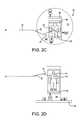
- FIG. 3Ais a side view of an embodiment of the system of FIG. 1 , showing the patient in a first treatment position;
- FIG. 3Bis a side view of an embodiment of the system of FIG. 1 , showing the patient in a second treatment position;
- FIG. 4Ais a side view of an embodiment of the system of FIG. 1 , showing the patient table in relation to the beam, and showing the motion of the beam through the treatment cycle, but not showing rotation of the table;
- FIG. 4Bis a top view of an embodiment of the patient table of FIG. 4A ;
- FIG. 5is a side view of another embodiment of the system of the present invention.
- FIG. 6is a graph showing the respective angles of rotation of the beam and the platform, in which each function line shows a different direction of rotation.
- FIG. 1shows a representation of an embodiment of the system 10 of the present invention.
- a beam 12is generated by a beam generator 14 , which may be a cyclotron or similar device. While the beam may be any type of beam, including optical and particle beams, “beam” or “particle beam” as used herein is intended to describe any suitable type of beam.
- the beamis directed along a path 16 by path guides 18 , which are preferably magnets for a particle beam, but which may be any device suitable for deflecting the path of a given type of beam. As shown in FIGS. 2A-2D , the path 16 is bent at a first angle ⁇ and a second angle ⁇ .
- the beam pathvaries in a rotation around axis B, which is coaxial with the path of the beam 12 prior to deflection at the first angle ⁇ , as shown in FIGS. 1 and 4A .
- the angles ⁇ and ⁇can be any angles that provide the desired system geometry.
- the rotation of the beam pathforms a cone 20 with a fixed isocenter 22 at its apex and located along the axis B. The rotation may occur in either the clockwise or counterclockwise direction.
- the beam pathvaries, the beam continually passes through the isocenter, which is positioned at a target site 24 located within or on a body 26 , including but not limited to the site of a tumor inside the patient's body.
- the systemmay be used to direct a beam of any type to a target site on a body generally, the system will be generally described herein in the context of the treatment of a tumor in a human patient.
- the assembly 30includes a rotating platform 32 and a patient cradle 34 .
- the cradleincludes a patient tray 36 mounted to a frame 38 .
- the frame and trayare movable in multiple degrees of freedom, and may be moved by motors 40 - 46 positioned to adjust the position of the tray in any number of desired directions, in order that the target within the patient remains at the isocenter 22 during rotation of the patient assembly 30 .
- motors 40 - 46positioned to adjust the position of the tray in any number of desired directions, in order that the target within the patient remains at the isocenter 22 during rotation of the patient assembly 30 .
- motor 40moves the frame 38 in a direction X; motor 42 moves the frame 38 in a direction Y perpendicular to direction X, and motor 44 moves the tray 36 in along axis P.
- Motor 46allows the angle ⁇ , shown in FIG. 3B , to be adjusted if needed; e.g., to compensate for deflection of the patient cradle or tray, or to adjust the angle at which the beam enters the patient's body. These degrees of freedom allow the patient to be positioned so that the platform's axis of rotation Z passes through the tumor located at target site 24 .
- the rotation of the assembly 30 about axis Zmay be in either the clockwise or counterclockwise direction, and corresponds with the rotation of the beam path 16 about axis B.
- the respective rotationsare synchronized so that the beam 12 always contacts the patient 26 at roughly a right angle to the patient's body without the use of an large-diameter gantry structure, as is the case for a horizontal patient.
- the respective rates of rotation of the assembly and beam pathneed not be constant.
- the relationship between the rates of rotation of the assembly and the beam, respectivelyneed not be linear.
- FIG. 6One embodiment of the relationship between the rates of rotation is shown in FIG. 6 , wherein each function line depicts a different direction of rotation of the beam path.
- FIGS. 2A-2Dshow how the beam 12 contacts the patient's body at various times during a treatment cycle.
- FIG. 2Ais a side view of the arrangement at a first point in the cycle.
- the patientis located on the tray 36 of the assembly 30 .
- the beam 12is directed through first and second angles ⁇ and ⁇ , respectively, and contacts the tumor located at target site 24 .
- the position of the patientmay be varied in order to maintain the target site in a constant location in space, and to maintain beam contact with the site throughout the treatment cycle.
- FIG. 2Bis a side view of a second point in the cycle. As shown in FIGS. 2A and 2B , the beam contacts the target site 24 at approximately 90 degrees from the axis P.
- FIG. 1is a side view of the arrangement at a first point in the cycle.
- the patientis located on the tray 36 of the assembly 30 .
- the beam 12is directed through first and second angles ⁇ and ⁇ , respectively, and contacts the tumor located at target site 24
- FIG. 2Cis a view of a third point in the treatment cycle, as seen from the same location in space as FIGS. 2A and 2B .
- the assembly 30has rotated 90 degrees around axis Z, which runs through roughly the center of the tumor located at the target site 24 . Because the assembly preferably rotates around an axis passing through the center of the target site, the target site's spatial orientation preferably remains constant; i.e., the site does not move laterally, but rather merely rotates in place.
- the rates of rotationare synchronized in a non-linear fashion, so that the beam is still contacting the target site at an angle of roughly 90 degrees from the axis P. As seen in FIG.
- the assembly 30has rotated 180 degrees from its orientation shown in FIG. 2A .
- the beam 12has also rotated a corresponding amount, and still contacts the target site 24 at approximately 90 degrees from the axis P.
- the beam isocenter 22remains aligned with the target site 24 throughout the treatment cycle.
- the assembly 30In order to properly position the patient for treatment and ensure that the beam isocenter remains fixed on the target site, the assembly 30 should be highly adjustable. As seen in FIGS. 3A , 3 B, and 4 B, the cradle 34 , frame 38 , and tray 36 may all be adjusted for position.
- the assembly 30includes a platform 32 , which rotates around an axis Z passing vertically through the target site's approximate center. In order to accomplish this, the frame 38 can be adjusted in directions X and Y, and the tray 36 can be adjusted along axis P to compensate for location of the target site within the body.
- the rotating platform 32preferably rotates about its own center axis.
- the motor 40is used to position the frame 38 in the X direction.
- the motor 42is used to position the frame in the Y-direction.
- the motor 44is used to position the tray 36 along the axis P, and the motor 46 is used to set the angle ⁇ of the tray.
- the traymay be set at any desired angle ⁇ at which the patient is comfortable, but the angle ⁇ is preferably maintained at an angle corresponding to the chosen ⁇ and ⁇ angles so that the beam enters the patient's body at the desired angle. While the beam preferably enters the patient's body at a roughly 90-degree angle, any suitable angle may be chosen to minimize potential damage to healthy intermediate tissue.
- the angle ⁇will generally be set between approximately 30 and 60 degrees, as shown in FIG. 5 .
- the adjustability of angle ⁇may also be used to compensate for deflection of the cradle 34 or frame 38 under a range of patient sizes or weights.
- the frameis sturdy enough to support the weight of the patient, and may be made of any suitable material, including metal or plastic. While the frame is depicted as being supported at its lower edge, it and the cradle 34 may be any shape or material that does not interfere with the beam path 16 .
- the beam pathmay be adjusted to ensure full coverage of the target site.
- the path followed by the particles or other particlesmay be varied in either or both of two ways for the purpose of accurately covering the full volume of an extended tumor, whose center may lie at the nominal isocenter of the beam.
- One variationis to introduce a computer-controlled variable-thickness “wedge”, whose effect will be to alter slightly the depth at which the beam deposits its energy, thus reaching from the near side to the far side of the tumor at each angle by which it is irradiated.
- the other variationis to apply an additional small magnetic field or other deflecting method, so as to move the beam slightly from side to side or in a raster pattern, thus covering the (possibly irregular) width of the tumor.
- FIG. 5shows an alternative embodiment of the invention, in which the invention is used to perform a scan, such as a CT scan, of a patient's body.
- the beamcan be any type of beam necessary to perform the scan.
- a detecting device 50can be included in the apparatus. If a 360 degree scan is needed, the detecting device 50 can rotate about an axis M so as to maintain alignment with the beam 12 , which may be a thin “pencil” beam, or a beam that forms a cone shape as shown in FIG. 5 .
- the beammay be a particle beam, or it may be another type of beam, such as an x-ray beam generated by a device included along the path of the particle beam.
- the detectormay be any type that is suitable for detecting the beam generated.
- the beam and patientrotate in a manner identical to that expected to be used during therapy; however, the patient may or may not rotate, depending on the type of image desired.
- the scanis a linear scan, i.e., along a length of the patient's body, the assembly may remain stationary, and the frame or tray may be moved to ensure proper coverage by the beam of the area to be scanned.
- any or all of the angles ⁇ , ⁇ , or ⁇may be varied to change the location in which the beam contacts the patient's body, and the detector may move in a corresponding manner.
- the scanmay be performed using the same method or device on any object requiring a 3-D scan.
- FIG. 6shows a graphical representation of the relation between the conical rotation of the beam about its horizontal axis and the rotation of the patient about its vertical axis, as required to have the beam traverse the exact circumference of the body.
- intentional, controlled variation from the angles depicted in FIG. 6can widen the points of entry to a belt of varying width, further reducing the dose to the intervening tissue, while still being focused on the target tumor.
- the beamintersects the patient body at the front.
- the beamintersects the patient body at the back.
- the intermediate casesare less simple, as two positions of the beam are possible. To clarify this, consider a small counterclockwise rotation (as seen from above) of the patient from the position in FIG. 2A toward the viewer. There are then two points on the circumference of the body that intersect the cone 20 , one corresponding to a point closer to the viewer, and the other to a point away from the viewer.
- the formerentails a counter-clockwise rotation of the beam around the cone (as seen from the patient), and the other entails a clockwise rotation.
- the beammust be somewhat above or somewhat below the horizontal.
- the relationship between the two anglesis non-linear in the manner shown in FIG. 6 . Either of the curved paths may be followed, as long as the one chosen is consistent for the full 360° or 2 ⁇ radians of rotation.
Landscapes
- Health & Medical Sciences (AREA)
- Engineering & Computer Science (AREA)
- Biomedical Technology (AREA)
- Physics & Mathematics (AREA)
- General Health & Medical Sciences (AREA)
- Pathology (AREA)
- Nuclear Medicine, Radiotherapy & Molecular Imaging (AREA)
- Radiology & Medical Imaging (AREA)
- Life Sciences & Earth Sciences (AREA)
- Animal Behavior & Ethology (AREA)
- Public Health (AREA)
- Veterinary Medicine (AREA)
- High Energy & Nuclear Physics (AREA)
- General Engineering & Computer Science (AREA)
- Spectroscopy & Molecular Physics (AREA)
- Radiation-Therapy Devices (AREA)
Abstract
Description
Claims (16)
Priority Applications (4)
| Application Number | Priority Date | Filing Date | Title |
|---|---|---|---|
| US12/391,831US8053745B2 (en) | 2009-02-24 | 2009-02-24 | Device and method for administering particle beam therapy |
| PCT/US2010/020208WO2010098894A1 (en) | 2009-02-24 | 2010-01-06 | Device and method for administering particle beam therapy |
| EP10746578.3AEP2401034A4 (en) | 2009-02-24 | 2010-01-06 | Device and method for administering particle beam therapy |
| JP2011551077AJP5307903B2 (en) | 2009-02-24 | 2010-01-06 | Apparatus and method for performing particle beam therapy |
Applications Claiming Priority (1)
| Application Number | Priority Date | Filing Date | Title |
|---|---|---|---|
| US12/391,831US8053745B2 (en) | 2009-02-24 | 2009-02-24 | Device and method for administering particle beam therapy |
Publications (2)
| Publication Number | Publication Date |
|---|---|
| US20100213385A1 US20100213385A1 (en) | 2010-08-26 |
| US8053745B2true US8053745B2 (en) | 2011-11-08 |
Family
ID=42630148
Family Applications (1)
| Application Number | Title | Priority Date | Filing Date |
|---|---|---|---|
| US12/391,831Expired - Fee RelatedUS8053745B2 (en) | 2009-02-24 | 2009-02-24 | Device and method for administering particle beam therapy |
Country Status (4)
| Country | Link |
|---|---|
| US (1) | US8053745B2 (en) |
| EP (1) | EP2401034A4 (en) |
| JP (1) | JP5307903B2 (en) |
| WO (1) | WO2010098894A1 (en) |
Cited By (29)
| Publication number | Priority date | Publication date | Assignee | Title |
|---|---|---|---|---|
| US8309941B2 (en)* | 2008-05-22 | 2012-11-13 | Vladimir Balakin | Charged particle cancer therapy and patient breath monitoring method and apparatus |
| US8791656B1 (en) | 2013-05-31 | 2014-07-29 | Mevion Medical Systems, Inc. | Active return system |
| US8907311B2 (en) | 2005-11-18 | 2014-12-09 | Mevion Medical Systems, Inc. | Charged particle radiation therapy |
| US8927950B2 (en) | 2012-09-28 | 2015-01-06 | Mevion Medical Systems, Inc. | Focusing a particle beam |
| US8933650B2 (en) | 2007-11-30 | 2015-01-13 | Mevion Medical Systems, Inc. | Matching a resonant frequency of a resonant cavity to a frequency of an input voltage |
| US8941083B2 (en) | 2007-10-11 | 2015-01-27 | Mevion Medical Systems, Inc. | Applying a particle beam to a patient |
| US8952634B2 (en) | 2004-07-21 | 2015-02-10 | Mevion Medical Systems, Inc. | Programmable radio frequency waveform generator for a synchrocyclotron |
| US8970137B2 (en) | 2007-11-30 | 2015-03-03 | Mevion Medical Systems, Inc. | Interrupted particle source |
| US9155186B2 (en) | 2012-09-28 | 2015-10-06 | Mevion Medical Systems, Inc. | Focusing a particle beam using magnetic field flutter |
| US9185789B2 (en) | 2012-09-28 | 2015-11-10 | Mevion Medical Systems, Inc. | Magnetic shims to alter magnetic fields |
| US9274067B2 (en) | 2011-03-07 | 2016-03-01 | Loma Linda University Medical Center | Systems, devices and methods related to calibration of a proton computed tomography scanner |
| US9301384B2 (en) | 2012-09-28 | 2016-03-29 | Mevion Medical Systems, Inc. | Adjusting energy of a particle beam |
| US9545528B2 (en) | 2012-09-28 | 2017-01-17 | Mevion Medical Systems, Inc. | Controlling particle therapy |
| US9622335B2 (en) | 2012-09-28 | 2017-04-11 | Mevion Medical Systems, Inc. | Magnetic field regenerator |
| US9661736B2 (en) | 2014-02-20 | 2017-05-23 | Mevion Medical Systems, Inc. | Scanning system for a particle therapy system |
| US9681531B2 (en) | 2012-09-28 | 2017-06-13 | Mevion Medical Systems, Inc. | Control system for a particle accelerator |
| US9723705B2 (en) | 2012-09-28 | 2017-08-01 | Mevion Medical Systems, Inc. | Controlling intensity of a particle beam |
| US9730308B2 (en) | 2013-06-12 | 2017-08-08 | Mevion Medical Systems, Inc. | Particle accelerator that produces charged particles having variable energies |
| US9950194B2 (en) | 2014-09-09 | 2018-04-24 | Mevion Medical Systems, Inc. | Patient positioning system |
| US9962560B2 (en) | 2013-12-20 | 2018-05-08 | Mevion Medical Systems, Inc. | Collimator and energy degrader |
| US10254739B2 (en) | 2012-09-28 | 2019-04-09 | Mevion Medical Systems, Inc. | Coil positioning system |
| US10258810B2 (en) | 2013-09-27 | 2019-04-16 | Mevion Medical Systems, Inc. | Particle beam scanning |
| US10646728B2 (en) | 2015-11-10 | 2020-05-12 | Mevion Medical Systems, Inc. | Adaptive aperture |
| US10653892B2 (en) | 2017-06-30 | 2020-05-19 | Mevion Medical Systems, Inc. | Configurable collimator controlled using linear motors |
| US10675487B2 (en) | 2013-12-20 | 2020-06-09 | Mevion Medical Systems, Inc. | Energy degrader enabling high-speed energy switching |
| US10925147B2 (en) | 2016-07-08 | 2021-02-16 | Mevion Medical Systems, Inc. | Treatment planning |
| US11103730B2 (en) | 2017-02-23 | 2021-08-31 | Mevion Medical Systems, Inc. | Automated treatment in particle therapy |
| US11291861B2 (en) | 2019-03-08 | 2022-04-05 | Mevion Medical Systems, Inc. | Delivery of radiation by column and generating a treatment plan therefor |
| US12245355B2 (en) | 2021-02-19 | 2025-03-04 | Mevion Medical Systems, Inc. | Gantry for a particle therapy system |
Families Citing this family (1)
| Publication number | Priority date | Publication date | Assignee | Title |
|---|---|---|---|---|
| EP3573075B1 (en) | 2018-05-21 | 2022-01-26 | CERN - European Organization For Nuclear Research | A gantry and apparatus for focussing beams of charged particles |
Citations (30)
| Publication number | Priority date | Publication date | Assignee | Title |
|---|---|---|---|---|
| US3257556A (en) | 1963-10-03 | 1966-06-21 | American Sterilizer Co | Tiltable surgical table suited for radiograph-urology procedures |
| US3986026A (en) | 1975-11-14 | 1976-10-12 | The United States Of America As Represented By The United States Energy Research And Development Administration | Apparatus for proton radiography |
| US5117829A (en) | 1989-03-31 | 1992-06-02 | Loma Linda University Medical Center | Patient alignment system and procedure for radiation treatment |
| US5760395A (en) | 1996-04-18 | 1998-06-02 | Universities Research Assoc., Inc. | Method and apparatus for laser-controlled proton beam radiology |
| US5847401A (en) | 1996-11-01 | 1998-12-08 | Atomic Energy Of Canada Limited | Simultaneous double sided irradiation |
| US5895926A (en) | 1995-02-15 | 1999-04-20 | Loma Linda University Medical Center | Beamline control and security system for a radiation treatment facility |
| US6087670A (en) | 1996-12-03 | 2000-07-11 | Hitachi, Ltd. | Synchrotron type accelerator and medical treatment system employing the same |
| US6275564B1 (en) | 1998-08-05 | 2001-08-14 | Moshe Ein-Gal | Positioner for radiation treatment |
| US6639234B1 (en) | 1999-02-19 | 2003-10-28 | Gesellschaft Fuer Schwerionenforschung Mbh | Method for checking beam steering in an ion beam therapy system |
| US6683318B1 (en) | 1998-09-11 | 2004-01-27 | Gesellschaft Fuer Schwerionenforschung Mbh | Ion beam therapy system and a method for operating the system |
| US6730921B2 (en) | 2000-03-07 | 2004-05-04 | Gesellschaft Fuer Schwerionenforschung Mbh | Ion beam system for irradiating tumor tissues |
| US6809325B2 (en) | 2001-02-05 | 2004-10-26 | Gesellschaft Fuer Schwerionenforschung Mbh | Apparatus for generating and selecting ions used in a heavy ion cancer therapy facility |
| US6814694B1 (en) | 1999-06-25 | 2004-11-09 | Paul Scherrer Institut | Device for carrying out proton therapy |
| US20060050847A1 (en) | 2000-02-18 | 2006-03-09 | William Beaumont Hospital | Cone beam computed tomography with a flat panel imager |
| US20060159220A1 (en)* | 2003-07-15 | 2006-07-20 | Heuscher Dominic J | Computed tomograhpy with large gantry bore |
| US7084410B2 (en) | 2003-01-02 | 2006-08-01 | Loma Linda University Medical Center | Configuration management and retrieval system for proton beam therapy system |
| US7154108B2 (en) | 2003-10-24 | 2006-12-26 | Hitachi, Ltd. | Particle therapy system |
| US20070034812A1 (en) | 2003-12-02 | 2007-02-15 | Chang-Ming Ma | Method of modulating laser-accelerated protons for radiation therapy |
| US20070176125A1 (en) | 2004-07-28 | 2007-08-02 | Takayoshi Natori | Particle beam therapy system and control system for particle beam therapy |
| US7280633B2 (en) | 2003-08-12 | 2007-10-09 | Loma Linda University Medical Center | Path planning and collision avoidance for movement of instruments in a radiation therapy environment |
| US7317192B2 (en) | 2003-06-02 | 2008-01-08 | Fox Chase Cancer Center | High energy polyenergetic ion selection systems, ion beam therapy systems, and ion beam treatment centers |
| US20080009717A1 (en)* | 2006-05-05 | 2008-01-10 | Klaus Herrmann | Method for generating a medical image and a medical imaging system |
| US7345292B2 (en) | 2003-03-07 | 2008-03-18 | Hitachi, Ltd. | Particle beam therapy system |
| US20080093567A1 (en) | 2005-11-18 | 2008-04-24 | Kenneth Gall | Charged particle radiation therapy |
| US20080137805A1 (en) | 2006-07-28 | 2008-06-12 | Jan Forster | Computer tomograph |
| US20080161676A1 (en) | 2003-03-18 | 2008-07-03 | Esaote S.P.A. | Magnetic resonance imaging apparatus |
| US20080234531A1 (en)* | 2007-03-23 | 2008-09-25 | Nanolife Holdings, Llc | Bi-polar treatment facility for treating target cells with both positive and negative ions |
| US20080317216A1 (en) | 2007-05-24 | 2008-12-25 | Leon Lifshitz | Method and apparatus for teletherapy positioning and validation |
| US20090202045A1 (en)* | 2008-02-12 | 2009-08-13 | Varian Medical Systems Technologies, Inc. | Treatment booth for radiation therapy |
| US20100329422A1 (en)* | 2007-10-24 | 2010-12-30 | Elekta Ab (Publ) | Radiotherapeutic apparatus |
- 2009
- 2009-02-24USUS12/391,831patent/US8053745B2/ennot_activeExpired - Fee Related
- 2010
- 2010-01-06WOPCT/US2010/020208patent/WO2010098894A1/enactiveApplication Filing
- 2010-01-06EPEP10746578.3Apatent/EP2401034A4/ennot_activeWithdrawn
- 2010-01-06JPJP2011551077Apatent/JP5307903B2/ennot_activeExpired - Fee Related
Patent Citations (33)
| Publication number | Priority date | Publication date | Assignee | Title |
|---|---|---|---|---|
| US3257556A (en) | 1963-10-03 | 1966-06-21 | American Sterilizer Co | Tiltable surgical table suited for radiograph-urology procedures |
| US3986026A (en) | 1975-11-14 | 1976-10-12 | The United States Of America As Represented By The United States Energy Research And Development Administration | Apparatus for proton radiography |
| US5117829A (en) | 1989-03-31 | 1992-06-02 | Loma Linda University Medical Center | Patient alignment system and procedure for radiation treatment |
| US5895926A (en) | 1995-02-15 | 1999-04-20 | Loma Linda University Medical Center | Beamline control and security system for a radiation treatment facility |
| US5760395A (en) | 1996-04-18 | 1998-06-02 | Universities Research Assoc., Inc. | Method and apparatus for laser-controlled proton beam radiology |
| US5847401A (en) | 1996-11-01 | 1998-12-08 | Atomic Energy Of Canada Limited | Simultaneous double sided irradiation |
| US6087670A (en) | 1996-12-03 | 2000-07-11 | Hitachi, Ltd. | Synchrotron type accelerator and medical treatment system employing the same |
| US6275564B1 (en) | 1998-08-05 | 2001-08-14 | Moshe Ein-Gal | Positioner for radiation treatment |
| US6683318B1 (en) | 1998-09-11 | 2004-01-27 | Gesellschaft Fuer Schwerionenforschung Mbh | Ion beam therapy system and a method for operating the system |
| US6639234B1 (en) | 1999-02-19 | 2003-10-28 | Gesellschaft Fuer Schwerionenforschung Mbh | Method for checking beam steering in an ion beam therapy system |
| US6814694B1 (en) | 1999-06-25 | 2004-11-09 | Paul Scherrer Institut | Device for carrying out proton therapy |
| US20060050847A1 (en) | 2000-02-18 | 2006-03-09 | William Beaumont Hospital | Cone beam computed tomography with a flat panel imager |
| US6730921B2 (en) | 2000-03-07 | 2004-05-04 | Gesellschaft Fuer Schwerionenforschung Mbh | Ion beam system for irradiating tumor tissues |
| US6809325B2 (en) | 2001-02-05 | 2004-10-26 | Gesellschaft Fuer Schwerionenforschung Mbh | Apparatus for generating and selecting ions used in a heavy ion cancer therapy facility |
| US7368740B2 (en) | 2003-01-02 | 2008-05-06 | Loma Linda University Medical Center | Configuration management and retrieval system for proton beam therapy system |
| US7084410B2 (en) | 2003-01-02 | 2006-08-01 | Loma Linda University Medical Center | Configuration management and retrieval system for proton beam therapy system |
| US7345292B2 (en) | 2003-03-07 | 2008-03-18 | Hitachi, Ltd. | Particle beam therapy system |
| US20080161676A1 (en) | 2003-03-18 | 2008-07-03 | Esaote S.P.A. | Magnetic resonance imaging apparatus |
| US7317192B2 (en) | 2003-06-02 | 2008-01-08 | Fox Chase Cancer Center | High energy polyenergetic ion selection systems, ion beam therapy systems, and ion beam treatment centers |
| US20060159220A1 (en)* | 2003-07-15 | 2006-07-20 | Heuscher Dominic J | Computed tomograhpy with large gantry bore |
| US7280633B2 (en) | 2003-08-12 | 2007-10-09 | Loma Linda University Medical Center | Path planning and collision avoidance for movement of instruments in a radiation therapy environment |
| US7247869B2 (en) | 2003-10-24 | 2007-07-24 | Hitachi, Ltd. | Particle therapy system |
| US7154108B2 (en) | 2003-10-24 | 2006-12-26 | Hitachi, Ltd. | Particle therapy system |
| US7268358B2 (en) | 2003-12-02 | 2007-09-11 | Fox Chase Cancer Center | Method of modulating laser-accelerated protons for radiation therapy |
| US20070034812A1 (en) | 2003-12-02 | 2007-02-15 | Chang-Ming Ma | Method of modulating laser-accelerated protons for radiation therapy |
| US20070176125A1 (en) | 2004-07-28 | 2007-08-02 | Takayoshi Natori | Particle beam therapy system and control system for particle beam therapy |
| US20080093567A1 (en) | 2005-11-18 | 2008-04-24 | Kenneth Gall | Charged particle radiation therapy |
| US20080009717A1 (en)* | 2006-05-05 | 2008-01-10 | Klaus Herrmann | Method for generating a medical image and a medical imaging system |
| US20080137805A1 (en) | 2006-07-28 | 2008-06-12 | Jan Forster | Computer tomograph |
| US20080234531A1 (en)* | 2007-03-23 | 2008-09-25 | Nanolife Holdings, Llc | Bi-polar treatment facility for treating target cells with both positive and negative ions |
| US20080317216A1 (en) | 2007-05-24 | 2008-12-25 | Leon Lifshitz | Method and apparatus for teletherapy positioning and validation |
| US20100329422A1 (en)* | 2007-10-24 | 2010-12-30 | Elekta Ab (Publ) | Radiotherapeutic apparatus |
| US20090202045A1 (en)* | 2008-02-12 | 2009-08-13 | Varian Medical Systems Technologies, Inc. | Treatment booth for radiation therapy |
Cited By (51)
| Publication number | Priority date | Publication date | Assignee | Title |
|---|---|---|---|---|
| US8952634B2 (en) | 2004-07-21 | 2015-02-10 | Mevion Medical Systems, Inc. | Programmable radio frequency waveform generator for a synchrocyclotron |
| USRE48047E1 (en) | 2004-07-21 | 2020-06-09 | Mevion Medical Systems, Inc. | Programmable radio frequency waveform generator for a synchrocyclotron |
| US8916843B2 (en) | 2005-11-18 | 2014-12-23 | Mevion Medical Systems, Inc. | Inner gantry |
| US9452301B2 (en) | 2005-11-18 | 2016-09-27 | Mevion Medical Systems, Inc. | Inner gantry |
| US10722735B2 (en) | 2005-11-18 | 2020-07-28 | Mevion Medical Systems, Inc. | Inner gantry |
| US8907311B2 (en) | 2005-11-18 | 2014-12-09 | Mevion Medical Systems, Inc. | Charged particle radiation therapy |
| US10279199B2 (en) | 2005-11-18 | 2019-05-07 | Mevion Medical Systems, Inc. | Inner gantry |
| US9925395B2 (en) | 2005-11-18 | 2018-03-27 | Mevion Medical Systems, Inc. | Inner gantry |
| US8941083B2 (en) | 2007-10-11 | 2015-01-27 | Mevion Medical Systems, Inc. | Applying a particle beam to a patient |
| US8933650B2 (en) | 2007-11-30 | 2015-01-13 | Mevion Medical Systems, Inc. | Matching a resonant frequency of a resonant cavity to a frequency of an input voltage |
| US8970137B2 (en) | 2007-11-30 | 2015-03-03 | Mevion Medical Systems, Inc. | Interrupted particle source |
| USRE48317E1 (en) | 2007-11-30 | 2020-11-17 | Mevion Medical Systems, Inc. | Interrupted particle source |
| US8309941B2 (en)* | 2008-05-22 | 2012-11-13 | Vladimir Balakin | Charged particle cancer therapy and patient breath monitoring method and apparatus |
| US9274067B2 (en) | 2011-03-07 | 2016-03-01 | Loma Linda University Medical Center | Systems, devices and methods related to calibration of a proton computed tomography scanner |
| US9880301B2 (en) | 2011-03-07 | 2018-01-30 | Loma Linda University Medical Center | Systems, devices and methods related to calibration of a proton computed tomography scanner |
| US10368429B2 (en) | 2012-09-28 | 2019-07-30 | Mevion Medical Systems, Inc. | Magnetic field regenerator |
| US10254739B2 (en) | 2012-09-28 | 2019-04-09 | Mevion Medical Systems, Inc. | Coil positioning system |
| US9681531B2 (en) | 2012-09-28 | 2017-06-13 | Mevion Medical Systems, Inc. | Control system for a particle accelerator |
| US9706636B2 (en) | 2012-09-28 | 2017-07-11 | Mevion Medical Systems, Inc. | Adjusting energy of a particle beam |
| US9723705B2 (en) | 2012-09-28 | 2017-08-01 | Mevion Medical Systems, Inc. | Controlling intensity of a particle beam |
| US8927950B2 (en) | 2012-09-28 | 2015-01-06 | Mevion Medical Systems, Inc. | Focusing a particle beam |
| US9622335B2 (en) | 2012-09-28 | 2017-04-11 | Mevion Medical Systems, Inc. | Magnetic field regenerator |
| US9301384B2 (en) | 2012-09-28 | 2016-03-29 | Mevion Medical Systems, Inc. | Adjusting energy of a particle beam |
| US9155186B2 (en) | 2012-09-28 | 2015-10-06 | Mevion Medical Systems, Inc. | Focusing a particle beam using magnetic field flutter |
| US9545528B2 (en) | 2012-09-28 | 2017-01-17 | Mevion Medical Systems, Inc. | Controlling particle therapy |
| US9185789B2 (en) | 2012-09-28 | 2015-11-10 | Mevion Medical Systems, Inc. | Magnetic shims to alter magnetic fields |
| US10155124B2 (en) | 2012-09-28 | 2018-12-18 | Mevion Medical Systems, Inc. | Controlling particle therapy |
| US8791656B1 (en) | 2013-05-31 | 2014-07-29 | Mevion Medical Systems, Inc. | Active return system |
| US9730308B2 (en) | 2013-06-12 | 2017-08-08 | Mevion Medical Systems, Inc. | Particle accelerator that produces charged particles having variable energies |
| US10456591B2 (en) | 2013-09-27 | 2019-10-29 | Mevion Medical Systems, Inc. | Particle beam scanning |
| US10258810B2 (en) | 2013-09-27 | 2019-04-16 | Mevion Medical Systems, Inc. | Particle beam scanning |
| US9962560B2 (en) | 2013-12-20 | 2018-05-08 | Mevion Medical Systems, Inc. | Collimator and energy degrader |
| US10675487B2 (en) | 2013-12-20 | 2020-06-09 | Mevion Medical Systems, Inc. | Energy degrader enabling high-speed energy switching |
| US9661736B2 (en) | 2014-02-20 | 2017-05-23 | Mevion Medical Systems, Inc. | Scanning system for a particle therapy system |
| US10434331B2 (en) | 2014-02-20 | 2019-10-08 | Mevion Medical Systems, Inc. | Scanning system |
| US11717700B2 (en) | 2014-02-20 | 2023-08-08 | Mevion Medical Systems, Inc. | Scanning system |
| US9950194B2 (en) | 2014-09-09 | 2018-04-24 | Mevion Medical Systems, Inc. | Patient positioning system |
| US10646728B2 (en) | 2015-11-10 | 2020-05-12 | Mevion Medical Systems, Inc. | Adaptive aperture |
| US11213697B2 (en) | 2015-11-10 | 2022-01-04 | Mevion Medical Systems, Inc. | Adaptive aperture |
| US10786689B2 (en) | 2015-11-10 | 2020-09-29 | Mevion Medical Systems, Inc. | Adaptive aperture |
| US11786754B2 (en) | 2015-11-10 | 2023-10-17 | Mevion Medical Systems, Inc. | Adaptive aperture |
| US12150235B2 (en) | 2016-07-08 | 2024-11-19 | Mevion Medical Systems, Inc. | Treatment planning |
| US10925147B2 (en) | 2016-07-08 | 2021-02-16 | Mevion Medical Systems, Inc. | Treatment planning |
| US11103730B2 (en) | 2017-02-23 | 2021-08-31 | Mevion Medical Systems, Inc. | Automated treatment in particle therapy |
| US10653892B2 (en) | 2017-06-30 | 2020-05-19 | Mevion Medical Systems, Inc. | Configurable collimator controlled using linear motors |
| US11291861B2 (en) | 2019-03-08 | 2022-04-05 | Mevion Medical Systems, Inc. | Delivery of radiation by column and generating a treatment plan therefor |
| US11311746B2 (en) | 2019-03-08 | 2022-04-26 | Mevion Medical Systems, Inc. | Collimator and energy degrader for a particle therapy system |
| US11717703B2 (en) | 2019-03-08 | 2023-08-08 | Mevion Medical Systems, Inc. | Delivery of radiation by column and generating a treatment plan therefor |
| US12161885B2 (en) | 2019-03-08 | 2024-12-10 | Mevion Medical Systems, Inc. | Delivery of radiation by column and generating a treatment plan therefor |
| US12168147B2 (en) | 2019-03-08 | 2024-12-17 | Mevion Medical Systems, Inc. | Collimator and energy degrader for a particle therapy system |
| US12245355B2 (en) | 2021-02-19 | 2025-03-04 | Mevion Medical Systems, Inc. | Gantry for a particle therapy system |
Also Published As
| Publication number | Publication date |
|---|---|
| JP2012518466A (en) | 2012-08-16 |
| EP2401034A1 (en) | 2012-01-04 |
| US20100213385A1 (en) | 2010-08-26 |
| JP5307903B2 (en) | 2013-10-02 |
| EP2401034A4 (en) | 2013-09-25 |
| WO2010098894A1 (en) | 2010-09-02 |
Similar Documents
| Publication | Publication Date | Title |
|---|---|---|
| US8053745B2 (en) | Device and method for administering particle beam therapy | |
| US9283407B2 (en) | Compact proton therapy system with energy selection onboard a rotatable gantry | |
| US7659528B2 (en) | Particle beam irradiation system | |
| US20140066755A1 (en) | Simultaneous Imaging and Particle Therapy Treatment system and Method | |
| JP2001346893A (en) | Radiotherapy equipment | |
| EP2353648B1 (en) | Particle beam treatment apparatus and irradiation nozzle apparatus | |
| US20140319383A1 (en) | Charged particle beam irradiation system | |
| JP2019524309A (en) | Gantry for particle beam therapy as an arm rotating on a vertical plane | |
| US20140048718A1 (en) | Charged particle beam irradiation apparatus | |
| US20220093285A1 (en) | Adaptive focus collimation of x-ray beams | |
| US10071263B1 (en) | Pivoting multileaf collimator and method for large field coverage | |
| US10179252B2 (en) | Irradiation device and method | |
| JP5700550B2 (en) | Charged particle beam irradiation equipment | |
| JP7677752B2 (en) | Particle beam irradiation system and particle beam irradiation facility | |
| JP4348470B2 (en) | Particle beam irradiation equipment | |
| CN108686307B (en) | Gantry system for particle beam therapy | |
| US10653895B2 (en) | Radiotherapy apparatus | |
| JP2024092424A (en) | Radiation Therapy Equipment | |
| JP2024097185A (en) | Particle beam irradiation system and X-ray imaging device arrangement method |
Legal Events
| Date | Code | Title | Description |
|---|---|---|---|
| ZAAA | Notice of allowance and fees due | Free format text:ORIGINAL CODE: NOA | |
| ZAAB | Notice of allowance mailed | Free format text:ORIGINAL CODE: MN/=. | |
| REMI | Maintenance fee reminder mailed | ||
| LAPS | Lapse for failure to pay maintenance fees | ||
| FP | Lapsed due to failure to pay maintenance fee | Effective date:20151108 | |
| FEPP | Fee payment procedure | Free format text:ENTITY STATUS SET TO UNDISCOUNTED (ORIGINAL EVENT CODE: BIG.); ENTITY STATUS OF PATENT OWNER: LARGE ENTITY Free format text:PETITION RELATED TO MAINTENANCE FEES FILED (ORIGINAL EVENT CODE: PMFP) | |
| MAFP | Maintenance fee payment | Free format text:PAYMENT OF MAINTENANCE FEE, 4TH YR, SMALL ENTITY (ORIGINAL EVENT CODE: M2551); ENTITY STATUS OF PATENT OWNER: LARGE ENTITY Year of fee payment:4 Free format text:PAYMENT OF MAINTENANCE FEE UNDER 1.28(C) (ORIGINAL EVENT CODE: M1559); ENTITY STATUS OF PATENT OWNER: LARGE ENTITY | |
| PRDP | Patent reinstated due to the acceptance of a late maintenance fee | Effective date:20180531 | |
| FEPP | Fee payment procedure | Free format text:SURCHARGE, PETITION TO ACCEPT PYMT AFTER EXP, UNINTENTIONAL. (ORIGINAL EVENT CODE: M2558); ENTITY STATUS OF PATENT OWNER: SMALL ENTITY | |
| FEPP | Fee payment procedure | Free format text:PETITION RELATED TO MAINTENANCE FEES GRANTED (ORIGINAL EVENT CODE: PMFG) | |
| STCF | Information on status: patent grant | Free format text:PATENTED CASE | |
| AS | Assignment | Owner name:JOHN FITZALLEN MOORE TRUST, ILLINOIS Free format text:DECREE OF DISTRIBUTION;ASSIGNOR:MOORE, JOHN FITZALLEN;REEL/FRAME:050259/0978 Effective date:20190822 | |
| AS | Assignment | Owner name:MOORE FAMILY PROPERTIES, LLC, ILLINOIS Free format text:ASSIGNMENT OF ASSIGNORS INTEREST;ASSIGNOR:JOHN FITZALLEN MOORE TRUST;REEL/FRAME:050774/0917 Effective date:20190916 | |
| FEPP | Fee payment procedure | Free format text:ENTITY STATUS SET TO SMALL (ORIGINAL EVENT CODE: SMAL); ENTITY STATUS OF PATENT OWNER: SMALL ENTITY | |
| FEPP | Fee payment procedure | Free format text:7.5 YR SURCHARGE - LATE PMT W/IN 6 MO, SMALL ENTITY (ORIGINAL EVENT CODE: M2555); ENTITY STATUS OF PATENT OWNER: SMALL ENTITY | |
| MAFP | Maintenance fee payment | Free format text:PAYMENT OF MAINTENANCE FEE, 8TH YR, SMALL ENTITY (ORIGINAL EVENT CODE: M2552); ENTITY STATUS OF PATENT OWNER: SMALL ENTITY Year of fee payment:8 | |
| FEPP | Fee payment procedure | Free format text:MAINTENANCE FEE REMINDER MAILED (ORIGINAL EVENT CODE: REM.); ENTITY STATUS OF PATENT OWNER: SMALL ENTITY | |
| LAPS | Lapse for failure to pay maintenance fees | Free format text:PATENT EXPIRED FOR FAILURE TO PAY MAINTENANCE FEES (ORIGINAL EVENT CODE: EXP.); ENTITY STATUS OF PATENT OWNER: SMALL ENTITY | |
| STCH | Information on status: patent discontinuation | Free format text:PATENT EXPIRED DUE TO NONPAYMENT OF MAINTENANCE FEES UNDER 37 CFR 1.362 | |
| FP | Lapsed due to failure to pay maintenance fee | Effective date:20231108 |