US8053691B2 - Park inhibition solenoid assembly - Google Patents
Park inhibition solenoid assemblyDownload PDFInfo
- Publication number
- US8053691B2 US8053691B2US12/326,561US32656108AUS8053691B2US 8053691 B2US8053691 B2US 8053691B2US 32656108 AUS32656108 AUS 32656108AUS 8053691 B2US8053691 B2US 8053691B2
- Authority
- US
- United States
- Prior art keywords
- armature
- detent
- assembly
- inner sleeve
- bearing element
- Prior art date
- Legal status (The legal status is an assumption and is not a legal conclusion. Google has not performed a legal analysis and makes no representation as to the accuracy of the status listed.)
- Expired - Fee Related, expires
Links
Images


Classifications
- F—MECHANICAL ENGINEERING; LIGHTING; HEATING; WEAPONS; BLASTING
- F16—ENGINEERING ELEMENTS AND UNITS; GENERAL MEASURES FOR PRODUCING AND MAINTAINING EFFECTIVE FUNCTIONING OF MACHINES OR INSTALLATIONS; THERMAL INSULATION IN GENERAL
- F16H—GEARING
- F16H63/00—Control outputs from the control unit to change-speed- or reversing-gearings for conveying rotary motion or to other devices than the final output mechanism
- F16H63/02—Final output mechanisms therefor; Actuating means for the final output mechanisms
- F16H63/30—Constructional features of the final output mechanisms
- F16H63/34—Locking or disabling mechanisms
- F16H63/3416—Parking lock mechanisms or brakes in the transmission
- F16H63/3458—Parking lock mechanisms or brakes in the transmission with electric actuating means, e.g. shift by wire
- F16H63/3475—Parking lock mechanisms or brakes in the transmission with electric actuating means, e.g. shift by wire using solenoids
- F—MECHANICAL ENGINEERING; LIGHTING; HEATING; WEAPONS; BLASTING
- F16—ENGINEERING ELEMENTS AND UNITS; GENERAL MEASURES FOR PRODUCING AND MAINTAINING EFFECTIVE FUNCTIONING OF MACHINES OR INSTALLATIONS; THERMAL INSULATION IN GENERAL
- F16H—GEARING
- F16H61/00—Control functions within control units of change-speed- or reversing-gearings for conveying rotary motion ; Control of exclusively fluid gearing, friction gearing, gearings with endless flexible members or other particular types of gearing
- F16H61/22—Locking of the control input devices
- F16H2061/223—Electrical gear shift lock, e.g. locking of lever in park or neutral position by electric means if brake is not applied; Key interlock, i.e. locking the key if lever is not in park position
- Y—GENERAL TAGGING OF NEW TECHNOLOGICAL DEVELOPMENTS; GENERAL TAGGING OF CROSS-SECTIONAL TECHNOLOGIES SPANNING OVER SEVERAL SECTIONS OF THE IPC; TECHNICAL SUBJECTS COVERED BY FORMER USPC CROSS-REFERENCE ART COLLECTIONS [XRACs] AND DIGESTS
- Y10—TECHNICAL SUBJECTS COVERED BY FORMER USPC
- Y10T—TECHNICAL SUBJECTS COVERED BY FORMER US CLASSIFICATION
- Y10T74/00—Machine element or mechanism
- Y10T74/20—Control lever and linkage systems
- Y10T74/20012—Multiple controlled elements
- Y10T74/20018—Transmission control
- Y10T74/20085—Restriction of shift, gear selection, or gear engagement
- Y10T74/20104—Shift element interlock
- Y10T74/2011—Shift element interlock with detent, recess, notch, or groove
Definitions
- the inventionrelates generally to a park inhibition solenoid assembly for a motor vehicle, and more particularly to a park inhibition solenoid assembly having a locking collar to prevent a motor vehicle from shifting into a Park mode.
- a typical multiple speed transmissionuses a combination of torque transmitting devices and gear sets to achieve a plurality of driving modes that include a plurality of out-of-Park driving modes and a Park mode.
- the out-of-Park driving modesgenerally include forward gear or speed ratios (i.e. a Drive mode), at least one reverse gear or speed ratio (i.e. a Reverse mode), and a Neutral mode.
- Selection of the various driving modesis typically accomplished by engaging a shift lever or other driver interface device that is connected by a shifting cable or other mechanical connection to the transmission.
- the selection of a driving modemay be controlled by an electronic transmission range selection (ETRS) system, also known as a “shift by wire” system.
- ETSelectronic transmission range selection
- ETRSIn an ETRS system, selection of the driving modes is accomplished through electronic signals communicated between the driver interface device and the transmission.
- the ETRS systemreduces mechanical components, increases instrument panel space, enhances styling options, and eliminates the possibility of shifting cable misalignment with transmission range selection levers.
- the ETRS systemincludes various components to engage the out-of-Park mode and Park mode, including a Park inhibition solenoid.
- the Park inhibition solenoidis operable to prevent the transmission from undesirably shifting from the out-of-Park mode to the Park mode. While typical Park inhibition solenoids are useful for their intended purpose, the employment of ETRS systems within applications having heavier fluid pressures and forces, such as trucks and sport utility vehicles, requires an increased ability to prevent undesirable engagement of the Park mode. Accordingly, there is room in the art for a Park inhibition solenoid assembly having locking features to prevent undesirable engagement of the Park mode while minimizing the size and weight of the solenoid.
- the present inventionprovides a Park inhibition solenoid assembly for preventing the undesirable shifting of a transmission from an out-of-Park mode to a Park mode.
- the Park inhibition solenoid assemblyincludes a follower and an armature slidably disposed within a valve body or housing and within a solenoid.
- the followeris moveable between an out-of-Park position and a Park position and the armature is moveable between an unlocked position and a locked position.
- the follower and armatureinclude detents for supporting a bearing or series of bearings about the circumference. The armature and bearing prevent the follower from moving from the out-of-Park position to the Park position when the armature is held in place in the locked position by the solenoid.
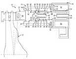
- FIG. 1is a schematic cross-sectional diagram of an embodiment of a Park inhibition solenoid assembly in a Park position according to the principles of the present invention
- FIG. 2is a schematic cross-sectional diagram of an embodiment of a Park inhibition solenoid assembly in a transitional position according to the principles of the present invention.
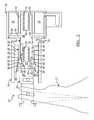
- FIG. 3is a schematic cross-sectional diagram of an embodiment of a Park inhibition solenoid assembly in an out-of-Park position according to the principles of the present invention.
- a Park inhibition solenoid assembly for use in a motor vehicleis generally indicated by reference number 10 .
- the Park inhibition solenoid assembly 10is preferably employed in an electronic range selection (ETRS) system in a transmission.
- ETRSelectronic range selection
- An exemplary ETRS system for use with the present inventionis disclosed in commonly assigned U.S. Pat. No. 6,983,668, hereby incorporated by reference as if fully disclosed herein. This design is an extension of that invention to handle applications with new fluid pressures and forces.
- the ETRS systemgenerally includes a plurality of servos, solenoids, valves, and a detent lever.
- An exemplary detent lever for use with the Park inhibition solenoid assembly 10is generally indicated by reference number 12 .
- the components of the ETRS systemcooperate to shift the transmission between an out-of-Park mode that preferably includes a Neutral, forward, and reverse speed ratios and a Park mode.
- the Park modeis intended to prevent movement of the motor vehicle.
- the Park inhibition solenoid assembly 10is operable to prevent the detent lever 12 from undesirably or unintentionally shifting between the out-of-Park mode and the Park mode, as will be described in greater detail below.
- the Park inhibition solenoid assembly 10includes a valve body or housing 14 , an inner sleeve 16 , a solenoid body 18 , an armature 20 , and a follower or outer sleeve 22 .
- the valve body/housing 14is generally cylindrical in shape and includes a bore surface 26 that defines a valve bore 28 .
- the valve body/housing 14further includes a first open end 30 that communicates with the valve bore 28 and a second open end 32 that communicates with the valve bore 28 opposite the first open end 30 .
- the inner sleeve 16includes a body portion 34 and a sleeve extension 36 that extends axially from the body portion 34 .
- the inner sleeve 16also includes an inner sleeve surface 38 that defines a bore 40 .
- the bore 40extends through the sleeve extension 36 and the body portion 34 .
- a first opening 42is located on an end of the sleeve extension 36 and communicates with the bore 40 and a second opening 44 is located on an end of the body portion 34 and communicates with the bore 40 .
- the sleeve extension 36includes a plurality of holes 46 that extend through the sleeve extension 36 and communicate with the bore 40 .
- a plurality of bearings 48are located within the holes 46 .
- the bearings 48are preferably ball bearings, though other types of bearings may be employed without departing from the scope of the present invention. Additionally, while only two bearings 48 are illustrated throughout the several views, it should be appreciated that any number of bearings 48 may be employed without departing from the scope of the present invention.
- the inner sleeve 16is attached or otherwise coupled to the valve body/housing 14 such that the inner sleeve 16 and the valve body/housing 14 are coaxial. More specifically, the sleeve extension 36 extends into the valve bore 28 of the valve body/housing 14 and the body portion 34 is at least partially located within the second opening 32 of the valve body/housing 14 .
- the solenoid body 18is attached or otherwise coupled to the body portion 34 of the inner sleeve 16 .
- the solenoid body 18 and the body portion 34cooperate to define a central cavity 50 within the solenoid body 18 .
- a solenoid coil 52is located within the central cavity 50 .
- the solenoid coil 52is selectively energizeable to produce a magnetic force, as is known in the art.
- the solenoid coil 52is supported within the cavity 50 by a hollow cylindrical shaft 54 coupled at an end thereof to the solenoid body 18 .
- the hollow cylindrical shaft 54is preferably coaxial with the valve body/housing 14 and the inner sleeve 16 .
- the armature 20includes a longitudinal body 58 and an arm 60 .
- the arm 60extends radially from the body 58 and is located between a first end 62 of the body 58 and a second end 64 of the body 58 .
- the first end 62includes a first aperture 66 that is coaxial with and extends into the body 58 .
- a tolerance piston 70is slidably disposed within the first aperture 66 .
- a tolerance spring 72is located within the first aperture 66 between the body 58 and the tolerance piston 70 . While the tolerance spring 72 is illustrated as a coiled spring in the present embodiment, it should be appreciated that any kind of biasing member may be employed without departing from the scope of the present invention.
- the tolerance spring 72 and tolerance piston 70cooperate to account for axial misalignment of the Park inhibition solenoid assembly 10 with respect to the detent lever 12 , as will be described in greater detail below.
- the second end 64includes a second aperture 68 that is coaxial with and extends into the body 58 .
- An armature spring 74is at least partially located within the second aperture 68 . While the armature spring 74 is illustrated as a coiled spring in the present embodiment, it should be appreciated that any kind of biasing member may be employed without departing from the scope of the present invention.
- the armature spring 74engages the solenoid body 18 , as will be described in greater detail below.
- the armature spring 74preferably has a stiffness less than that of the tolerance spring 72 .
- the armature 20also includes a detent 76 located on an outer surface 78 of the body 58 proximate to the first end 62 .
- the detent 76includes an angled front face 80 and an angled back face 82 .
- the detent 76is sized to accommodate the bearing 46 , as will be described in greater detail below.
- the detent 76may be a single circumferential groove that extends along the entire circumference of the body 58 or a plurality of discrete detents without departing from the scope of the present invention.
- the armature 20is slidably disposed within the bore 40 of the inner sleeve 16 such that the first end 62 extends from the first opening 42 of the inner sleeve 16 and is slidably disposed within the shaft 54 of the solenoid body 18 such that the second end 64 is located within the shaft 54 and the arm 60 extends into the cavity 50 .
- the armature 20is moveable relative to the valve body/housing 14 , the inner sleeve 16 , and the solenoid body 18 between a first or unlocked position, as illustrated in FIG. 1 , and a second or locked position, as illustrated in FIG. 3 .
- the armature spring 74is operable to bias the armature 20 to the unlocked position.
- the follower 22includes a head portion 84 and a collar 86 .
- the head portion 84is coupled or otherwise attached to the detent lever 12 .
- the collar 86extends longitudinally from the head portion 84 and includes an inner surface 88 .
- the inner surface 88defines a bore 90 .
- the follower 22further includes a detent 92 located on the inner surface 88 proximate to the head portion 84 .
- the detent 92includes a front face 94 and an angled back face 96 .
- the detent 92may be a single circumferential groove extending around the inner circumference of the collar 86 or a plurality of discrete detents without departing from the scope of the present invention.
- the follower 22is slidably disposed within the valve bore 28 of the valve body/housing 14 . More specifically, the head portion 84 extends out from the first open end 30 of the valve body/housing 14 and the collar 86 extends into the valve bore 28 between the valve body/housing 14 and the sleeve extension 36 of the inner sleeve 16 .
- the follower 22is moveable relative to the valve body/housing 14 , the inner sleeve 16 , and the solenoid body 18 between a Park position, as illustrated in FIG. 1 , and an out-of-Park position, as illustrated in FIG. 3 .
- the Park position and out-of-Park position of the follower 22correlate to the Park and out-of-Park positions of the detent lever 12 .
- the detent lever 12is moved by the ETRS system between the Park position and the out-of-Park position and the Park inhibition solenoid assembly 10 is operable to selectively lock the detent lever 12 in the out-of-Park position.
- the detent lever 12is positioned as shown in FIG. 1 .
- the detent lever 12in turn positions the follower 22 into the Park position such that the follower 22 does not engage the armature 20 .
- the armature 20is biased by the armature spring 74 into the unlocked position.
- the Park inhibit solenoid assembly 10does not inhibit the movement of the follower 22 and the detent lever 12 when the detent lever 12 and follower 22 are in the Park position.
- the detent lever 12begins to move the follower 22 to the out-of-Park position, as shown in FIG. 2 .
- the collar 86slides along the bearings 48 between the valve body/housing 14 and the inner sleeve 16 and the head portion 84 engages the tolerance piston 70 .
- the bearings 48are depressed into the detents 76 located in the armature 20 .
- the tolerance piston 70attempts to compresses the tolerance spring 72 .
- the stiffness of the tolerance spring 72is greater than that of the armature spring 74 and accordingly as the follower 22 moves to the out-of-Park position, the head portion urges the armature 20 to the locked position by compressing the armature spring 74 .
- the detent lever 12moves back to the Park position. Accordingly, the detent lever 12 moves the follower 22 back to the Park position and the armature spring 74 urges the armature 20 back to the unlocked position.
- the angled back face 96 of the detent 92engages the bearings 48 , and the bearings 48 in turn are moved downward into the detents 76 on the armature 20 .
- the solenoid coil 52is energized such that the arm 60 is magnetically drawn towards the solenoid coil 52 and therefore the armature 20 is held in place in the locked position. Accordingly, as the follower 22 is moved to the Park position by the detent lever 12 , the bearings 48 engage the angled back face 96 of the detent 92 . However, the bearings 48 are not urged into the detents 76 of the armature 20 since the armature 20 is locked from moving.
- the Park inhibition solenoid assembly 10is operable to selectively inhibit the movement of the detent lever 12 to the Park position during preselected conditions.
Landscapes
- Engineering & Computer Science (AREA)
- General Engineering & Computer Science (AREA)
- Mechanical Engineering (AREA)
- Gear-Shifting Mechanisms (AREA)
Abstract
Description
Claims (19)
Priority Applications (3)
| Application Number | Priority Date | Filing Date | Title |
|---|---|---|---|
| US12/326,561US8053691B2 (en) | 2007-12-21 | 2008-12-02 | Park inhibition solenoid assembly |
| DE102008062541.8ADE102008062541B4 (en) | 2007-12-21 | 2008-12-16 | Parking prevention solenoid assembly |
| CN200810188431XACN101469768B (en) | 2007-12-21 | 2008-12-22 | Park inhibition solenoid assembly |
Applications Claiming Priority (2)
| Application Number | Priority Date | Filing Date | Title |
|---|---|---|---|
| US1569007P | 2007-12-21 | 2007-12-21 | |
| US12/326,561US8053691B2 (en) | 2007-12-21 | 2008-12-02 | Park inhibition solenoid assembly |
Publications (2)
| Publication Number | Publication Date |
|---|---|
| US20090158877A1 US20090158877A1 (en) | 2009-06-25 |
| US8053691B2true US8053691B2 (en) | 2011-11-08 |
Family
ID=40787053
Family Applications (1)
| Application Number | Title | Priority Date | Filing Date |
|---|---|---|---|
| US12/326,561Expired - Fee RelatedUS8053691B2 (en) | 2007-12-21 | 2008-12-02 | Park inhibition solenoid assembly |
Country Status (3)
| Country | Link |
|---|---|
| US (1) | US8053691B2 (en) |
| CN (1) | CN101469768B (en) |
| DE (1) | DE102008062541B4 (en) |
Cited By (17)
| Publication number | Priority date | Publication date | Assignee | Title |
|---|---|---|---|---|
| US20130019709A1 (en)* | 2011-07-21 | 2013-01-24 | Hyundai Motor Company | Locking apparatus for parking brake |
| US20130199326A1 (en)* | 2010-06-04 | 2013-08-08 | Andreas Giefer | Shift-by-wire shifting device having mechanical parking lock actuation |
| US20140123799A1 (en)* | 2012-11-07 | 2014-05-08 | GM Global Technology Operations LLC | Valve integrated park inhibit solenoid assembly |
| US8763764B2 (en) | 2011-07-21 | 2014-07-01 | Hyundai Motor Company | Locking apparatus for parking brake |
| US8978862B2 (en) | 2013-02-07 | 2015-03-17 | Ford Global Technologies, Llc | Park brake actuator |
| US9080666B2 (en) | 2012-05-29 | 2015-07-14 | Gm Global Technology Operations, Inc. | Discrete mechanism for electronic transmission range selection |
| US20150239333A1 (en)* | 2014-02-25 | 2015-08-27 | GM Global Technology Operations LLC | Hybrid vehicle internal combustion engine |
| US9193336B2 (en) | 2012-11-28 | 2015-11-24 | Ford Global Technologies, Llc | Shift-by-wire system for actuating a vehicle park brake |
| US10161518B2 (en) | 2016-10-07 | 2018-12-25 | GM Global Technology Operations LLC | Park control system for a vehicle transmission |
| US10190685B2 (en) | 2016-10-17 | 2019-01-29 | GM Global Technology Operations LLC | Park control system for a vehicle transmission |
| US10377353B2 (en) | 2016-08-16 | 2019-08-13 | Ford Global Technologies, Llc | Park lock system for a hybrid electric vehicle |
| US10424429B2 (en) | 2017-12-18 | 2019-09-24 | GM Global Technology Operations LLC | Long stroke linear solenoid |
| US10495223B2 (en) | 2018-01-11 | 2019-12-03 | GM Global Technology Operations LLC | Shift by wire parking system |
| US10914378B2 (en) | 2019-05-07 | 2021-02-09 | GM Global Technology Operations LLC | Roller-gear shift by wire parking system |
| US20210172522A1 (en)* | 2019-12-05 | 2021-06-10 | Zf Friedrichshafen Ag | Device for Locking a Piston Rod of a Piston of an Actuator Which is Pressurizable in Order to Disengage a Parking Lock and is Spring-Loaded in Order to Engage the Parking Lock |
| US11261967B2 (en) | 2019-12-05 | 2022-03-01 | Zf Friedrichshafen Ag | Device for locking a piston rod of a piston of an actuator which is pressurizable in order to disengage a parking lock and is spring-loaded in order to engage the parking lock |
| US11984794B2 (en) | 2021-10-08 | 2024-05-14 | Dana Heavy Vehicle Systems Group, Llc | Cooling and lubrication system for an electric motor and gearbox assembly |
Families Citing this family (15)
| Publication number | Priority date | Publication date | Assignee | Title |
|---|---|---|---|---|
| JP4412355B2 (en)* | 2007-06-08 | 2010-02-10 | 株式会社デンソー | Shift range switching device |
| US9194401B2 (en)* | 2010-09-22 | 2015-11-24 | Nrg Enterprises, Inc. | Ultra lightweight and compact accumulator |
| US8567444B2 (en)* | 2010-10-08 | 2013-10-29 | GM Global Technology Operations LLC | Accumulator assembly |
| JP5503499B2 (en)* | 2010-11-01 | 2014-05-28 | ボッシュ株式会社 | Change lever lock control device, change lever unit equipped with the same, and change lever lock control method |
| DE102012013373A1 (en)* | 2012-07-04 | 2014-01-09 | Audi Ag | Adjustment device for a parking lock operation |
| CN103791077B (en)* | 2012-10-30 | 2016-03-30 | 上海索达传动机械有限公司 | The lockable mechanism of odd-side protective system after a kind of gearbox |
| KR101516176B1 (en)* | 2013-06-24 | 2015-05-04 | 에스엘 주식회사 | Solenoid apparatus for shift lever |
| US9394991B2 (en)* | 2013-11-26 | 2016-07-19 | GM Global Technology Operations LLC | Mechanism for vehicle transmission default to park |
| JP5863884B2 (en)* | 2014-06-05 | 2016-02-17 | 三菱電機株式会社 | Pressure accumulator |
| DE102017210068A1 (en)* | 2017-06-14 | 2018-12-20 | Zf Friedrichshafen Ag | Parking lock for an automatic transmission in a motor vehicle |
| CN107507712B (en)* | 2017-08-14 | 2019-09-27 | 江西亚欣澜宇科技有限公司 | A kind of electromagnetic switch that closure is firm |
| JP7393125B2 (en)* | 2018-03-13 | 2023-12-06 | フスコ オートモーティブ ホールディングス エル・エル・シー | Bistable solenoid with intermediate states |
| DE102018130485B4 (en)* | 2018-11-30 | 2020-06-18 | Schaeffler Technologies AG & Co. KG | Parking lock device for a transmission with a parking lock wheel |
| DE102019103105B3 (en) | 2019-02-08 | 2020-08-06 | Schaeffler Technologies AG & Co. KG | Locking device for a parking lock of a motor vehicle |
| CN112576704A (en)* | 2020-12-02 | 2021-03-30 | 重庆市农业科学院 | Gear shifting mechanism, speed change mechanism and power output mechanism |
Citations (9)
| Publication number | Priority date | Publication date | Assignee | Title |
|---|---|---|---|---|
| US3840088A (en)* | 1971-11-16 | 1974-10-08 | Nissan Motor | Inertia-responsive switching device |
| JPS61253224A (en) | 1985-04-30 | 1986-11-11 | Mazda Motor Corp | Vehicle automatic speed change gear |
| JPH01199035A (en) | 1988-02-01 | 1989-08-10 | Mitsubishi Agricult Mach Co Ltd | Hydraulic clutch actuating circuit for moving agricultural machine |
| US5078242A (en) | 1988-06-13 | 1992-01-07 | United Technologies Automotive, Inc. | Solenoid system for, for example, a brake/shift interlock for vehicular transmission control |
| US5179868A (en) | 1992-03-02 | 1993-01-19 | Roland Thibeault | Drive train enable-disable vehicle use device |
| US20040011609A1 (en) | 2000-08-02 | 2004-01-22 | Wolfgang Schmid | Parking brake, especially for an automotive gearbox |
| US6698555B2 (en) | 2000-10-19 | 2004-03-02 | Deere & Company | Motor vehicle parking brake control device |
| US6701797B2 (en) | 2001-01-04 | 2004-03-09 | Ford Global Technologies, Llc | Parking assembly |
| US6983668B2 (en) | 2003-06-03 | 2006-01-10 | General Motors Corporation | Park solenoid assembly for an internal electronic transmission range selection (ETRS) system |
Family Cites Families (3)
| Publication number | Priority date | Publication date | Assignee | Title |
|---|---|---|---|---|
| JP3849615B2 (en)* | 2002-08-27 | 2006-11-22 | トヨタ自動車株式会社 | Vehicle control device |
| DE102004012952A1 (en)* | 2004-03-17 | 2005-12-01 | Robert Bosch Gmbh | Spring-operated parking brake device |
| US7469610B2 (en)* | 2005-08-26 | 2008-12-30 | Gm Global Technology Operations, Inc. | Reverse and park inhibitor apparatus in a transmission control mechanism |
- 2008
- 2008-12-02USUS12/326,561patent/US8053691B2/ennot_activeExpired - Fee Related
- 2008-12-16DEDE102008062541.8Apatent/DE102008062541B4/ennot_activeExpired - Fee Related
- 2008-12-22CNCN200810188431XApatent/CN101469768B/ennot_activeExpired - Fee Related
Patent Citations (9)
| Publication number | Priority date | Publication date | Assignee | Title |
|---|---|---|---|---|
| US3840088A (en)* | 1971-11-16 | 1974-10-08 | Nissan Motor | Inertia-responsive switching device |
| JPS61253224A (en) | 1985-04-30 | 1986-11-11 | Mazda Motor Corp | Vehicle automatic speed change gear |
| JPH01199035A (en) | 1988-02-01 | 1989-08-10 | Mitsubishi Agricult Mach Co Ltd | Hydraulic clutch actuating circuit for moving agricultural machine |
| US5078242A (en) | 1988-06-13 | 1992-01-07 | United Technologies Automotive, Inc. | Solenoid system for, for example, a brake/shift interlock for vehicular transmission control |
| US5179868A (en) | 1992-03-02 | 1993-01-19 | Roland Thibeault | Drive train enable-disable vehicle use device |
| US20040011609A1 (en) | 2000-08-02 | 2004-01-22 | Wolfgang Schmid | Parking brake, especially for an automotive gearbox |
| US6698555B2 (en) | 2000-10-19 | 2004-03-02 | Deere & Company | Motor vehicle parking brake control device |
| US6701797B2 (en) | 2001-01-04 | 2004-03-09 | Ford Global Technologies, Llc | Parking assembly |
| US6983668B2 (en) | 2003-06-03 | 2006-01-10 | General Motors Corporation | Park solenoid assembly for an internal electronic transmission range selection (ETRS) system |
Cited By (22)
| Publication number | Priority date | Publication date | Assignee | Title |
|---|---|---|---|---|
| US20130199326A1 (en)* | 2010-06-04 | 2013-08-08 | Andreas Giefer | Shift-by-wire shifting device having mechanical parking lock actuation |
| US9382999B2 (en)* | 2010-06-04 | 2016-07-05 | Zf Friedrichshafen Ag | Shift-by-wire shifting device having mechanical parking lock actuation |
| US20130019709A1 (en)* | 2011-07-21 | 2013-01-24 | Hyundai Motor Company | Locking apparatus for parking brake |
| US8763764B2 (en) | 2011-07-21 | 2014-07-01 | Hyundai Motor Company | Locking apparatus for parking brake |
| US8844703B2 (en)* | 2011-07-21 | 2014-09-30 | Hyundai Motor Company | Locking apparatus for parking brake |
| US9080666B2 (en) | 2012-05-29 | 2015-07-14 | Gm Global Technology Operations, Inc. | Discrete mechanism for electronic transmission range selection |
| US20140123799A1 (en)* | 2012-11-07 | 2014-05-08 | GM Global Technology Operations LLC | Valve integrated park inhibit solenoid assembly |
| US9321435B2 (en)* | 2012-11-07 | 2016-04-26 | Gm Global Technology Operations Inc. | Valve integrated park inhibit solenoid assembly |
| US9193336B2 (en) | 2012-11-28 | 2015-11-24 | Ford Global Technologies, Llc | Shift-by-wire system for actuating a vehicle park brake |
| US8978862B2 (en) | 2013-02-07 | 2015-03-17 | Ford Global Technologies, Llc | Park brake actuator |
| US9381799B2 (en)* | 2014-02-25 | 2016-07-05 | GM Global Technology Operations LLC | Hybrid vehicle internal combustion engine |
| US20150239333A1 (en)* | 2014-02-25 | 2015-08-27 | GM Global Technology Operations LLC | Hybrid vehicle internal combustion engine |
| US10377353B2 (en) | 2016-08-16 | 2019-08-13 | Ford Global Technologies, Llc | Park lock system for a hybrid electric vehicle |
| US10161518B2 (en) | 2016-10-07 | 2018-12-25 | GM Global Technology Operations LLC | Park control system for a vehicle transmission |
| US10190685B2 (en) | 2016-10-17 | 2019-01-29 | GM Global Technology Operations LLC | Park control system for a vehicle transmission |
| US10424429B2 (en) | 2017-12-18 | 2019-09-24 | GM Global Technology Operations LLC | Long stroke linear solenoid |
| US10495223B2 (en) | 2018-01-11 | 2019-12-03 | GM Global Technology Operations LLC | Shift by wire parking system |
| US10914378B2 (en) | 2019-05-07 | 2021-02-09 | GM Global Technology Operations LLC | Roller-gear shift by wire parking system |
| US20210172522A1 (en)* | 2019-12-05 | 2021-06-10 | Zf Friedrichshafen Ag | Device for Locking a Piston Rod of a Piston of an Actuator Which is Pressurizable in Order to Disengage a Parking Lock and is Spring-Loaded in Order to Engage the Parking Lock |
| US11261967B2 (en) | 2019-12-05 | 2022-03-01 | Zf Friedrichshafen Ag | Device for locking a piston rod of a piston of an actuator which is pressurizable in order to disengage a parking lock and is spring-loaded in order to engage the parking lock |
| US11767914B2 (en)* | 2019-12-05 | 2023-09-26 | Zf Friedrichshafen Ag | Device for locking a piston rod of a piston of an actuator which is pressurizable in order to disengage a parking lock and is spring-loaded in order to engage the parking lock |
| US11984794B2 (en) | 2021-10-08 | 2024-05-14 | Dana Heavy Vehicle Systems Group, Llc | Cooling and lubrication system for an electric motor and gearbox assembly |
Also Published As
| Publication number | Publication date |
|---|---|
| CN101469768B (en) | 2013-01-02 |
| DE102008062541B4 (en) | 2020-03-05 |
| US20090158877A1 (en) | 2009-06-25 |
| DE102008062541A1 (en) | 2009-08-06 |
| CN101469768A (en) | 2009-07-01 |
Similar Documents
| Publication | Publication Date | Title |
|---|---|---|
| US8053691B2 (en) | Park inhibition solenoid assembly | |
| US9321435B2 (en) | Valve integrated park inhibit solenoid assembly | |
| US6983668B2 (en) | Park solenoid assembly for an internal electronic transmission range selection (ETRS) system | |
| US8316734B2 (en) | Operating device with a locking assembly | |
| US9810314B2 (en) | Rotary shifter assembly | |
| US4987968A (en) | In-line solenoid transmission interlock device | |
| US11168754B2 (en) | Parking mechanism | |
| US7270027B2 (en) | Detent lever assembly for an internal electronic transmission range selection (ETRS) system | |
| US7082851B2 (en) | Hydraulic servo assembly for an internal electronic transmission range selection (ETRS) system | |
| US6880419B2 (en) | Internal electronic transmission range selection (ETRS) system for an automatic transmission | |
| US20100275715A1 (en) | Shift cable assembly and connector therefor | |
| US6065581A (en) | Camming manual lever for pull-out load | |
| US6336373B1 (en) | Rotary electromagnetic actuator | |
| US7069807B2 (en) | Adjustable shift detent assembly | |
| US3361234A (en) | Transmission control mechanism | |
| CN109398268B (en) | Method for supporting a vehicle wash mode of a vehicle with internal electronic transmission range selection | |
| EP3246600A1 (en) | Transmission shifter with multi-position lockout | |
| US11543028B2 (en) | Transmission for a vehicle | |
| US10458542B2 (en) | Brake transmission shift interface pin assembly | |
| CN212106895U (en) | Hydraulic gear-shifting parking system of automatic transmission | |
| US20180202547A1 (en) | Actuator apparatus | |
| EP0356769B1 (en) | In-line solenoid transmission interlock device | |
| CA2106427A1 (en) | Removable overdrive lockout | |
| US10753468B2 (en) | Auxiliary transmission actuation mechanism in a manual dual clutch power transmission unit of a vehicle | |
| JPH02179573A (en) | Parking mechanism of automatic transmission |
Legal Events
| Date | Code | Title | Description |
|---|---|---|---|
| AS | Assignment | Owner name:GM GLOBAL TECHNOLOGY OPERATIONS, INC.,MICHIGAN Free format text:ASSIGNMENT OF ASSIGNORS INTEREST;ASSIGNORS:VERNACCHIA, MARK A.;POWELL, STEPHEN W.;REEL/FRAME:021917/0731 Effective date:20081201 Owner name:GM GLOBAL TECHNOLOGY OPERATIONS, INC., MICHIGAN Free format text:ASSIGNMENT OF ASSIGNORS INTEREST;ASSIGNORS:VERNACCHIA, MARK A.;POWELL, STEPHEN W.;REEL/FRAME:021917/0731 Effective date:20081201 | |
| AS | Assignment | Owner name:UNITED STATES DEPARTMENT OF THE TREASURY,DISTRICT Free format text:SECURITY AGREEMENT;ASSIGNOR:GM GLOBAL TECHNOLOGY OPERATIONS, INC.;REEL/FRAME:022201/0405 Effective date:20081231 Owner name:UNITED STATES DEPARTMENT OF THE TREASURY, DISTRICT Free format text:SECURITY AGREEMENT;ASSIGNOR:GM GLOBAL TECHNOLOGY OPERATIONS, INC.;REEL/FRAME:022201/0405 Effective date:20081231 | |
| AS | Assignment | Owner name:GM GLOBAL TECHNOLOGY OPERATIONS, INC.,MICHIGAN Free format text:CORRECTIVE ASSIGNMENT TO CORRECT THE THE FILING DATE FOR THE APPLICATION ON THE ASSIGNMENT SHOULD BE 02-DECEMBER-2008 PREVIOUSLY RECORDED ON REEL 021917 FRAME 0731. ASSIGNOR(S) HEREBY CONFIRMS THE THE FILING DATE FOR THE APPLICATION ON THE ASSIGNMENT STATES 01-DECEMBER-2008 AND IS INCORRECT;ASSIGNORS:VERNACCHIA, MARK A.;POWELL, STEPHEN W.;REEL/FRAME:022269/0889 Effective date:20081201 Owner name:GM GLOBAL TECHNOLOGY OPERATIONS, INC., MICHIGAN Free format text:CORRECTIVE ASSIGNMENT TO CORRECT THE THE FILING DATE FOR THE APPLICATION ON THE ASSIGNMENT SHOULD BE 02-DECEMBER-2008 PREVIOUSLY RECORDED ON REEL 021917 FRAME 0731. ASSIGNOR(S) HEREBY CONFIRMS THE THE FILING DATE FOR THE APPLICATION ON THE ASSIGNMENT STATES 01-DECEMBER-2008 AND IS INCORRECT;ASSIGNORS:VERNACCHIA, MARK A.;POWELL, STEPHEN W.;REEL/FRAME:022269/0889 Effective date:20081201 | |
| AS | Assignment | Owner name:CITICORP USA, INC. AS AGENT FOR BANK PRIORITY SECU Free format text:SECURITY AGREEMENT;ASSIGNOR:GM GLOBAL TECHNOLOGY OPERATIONS, INC.;REEL/FRAME:022554/0538 Effective date:20090409 Owner name:CITICORP USA, INC. AS AGENT FOR HEDGE PRIORITY SEC Free format text:SECURITY AGREEMENT;ASSIGNOR:GM GLOBAL TECHNOLOGY OPERATIONS, INC.;REEL/FRAME:022554/0538 Effective date:20090409 | |
| AS | Assignment | Owner name:GM GLOBAL TECHNOLOGY OPERATIONS, INC., MICHIGAN Free format text:RELEASE BY SECURED PARTY;ASSIGNOR:UNITED STATES DEPARTMENT OF THE TREASURY;REEL/FRAME:023126/0914 Effective date:20090709 Owner name:GM GLOBAL TECHNOLOGY OPERATIONS, INC., MICHIGAN Free format text:RELEASE BY SECURED PARTY;ASSIGNORS:CITICORP USA, INC. AS AGENT FOR BANK PRIORITY SECURED PARTIES;CITICORP USA, INC. AS AGENT FOR HEDGE PRIORITY SECURED PARTIES;REEL/FRAME:023155/0769 Effective date:20090814 Owner name:GM GLOBAL TECHNOLOGY OPERATIONS, INC.,MICHIGAN Free format text:RELEASE BY SECURED PARTY;ASSIGNOR:UNITED STATES DEPARTMENT OF THE TREASURY;REEL/FRAME:023126/0914 Effective date:20090709 Owner name:GM GLOBAL TECHNOLOGY OPERATIONS, INC.,MICHIGAN Free format text:RELEASE BY SECURED PARTY;ASSIGNORS:CITICORP USA, INC. AS AGENT FOR BANK PRIORITY SECURED PARTIES;CITICORP USA, INC. AS AGENT FOR HEDGE PRIORITY SECURED PARTIES;REEL/FRAME:023155/0769 Effective date:20090814 | |
| AS | Assignment | Owner name:UNITED STATES DEPARTMENT OF THE TREASURY, DISTRICT Free format text:SECURITY AGREEMENT;ASSIGNOR:GM GLOBAL TECHNOLOGY OPERATIONS, INC.;REEL/FRAME:023156/0313 Effective date:20090710 Owner name:UNITED STATES DEPARTMENT OF THE TREASURY,DISTRICT Free format text:SECURITY AGREEMENT;ASSIGNOR:GM GLOBAL TECHNOLOGY OPERATIONS, INC.;REEL/FRAME:023156/0313 Effective date:20090710 | |
| AS | Assignment | Owner name:UAW RETIREE MEDICAL BENEFITS TRUST, MICHIGAN Free format text:SECURITY AGREEMENT;ASSIGNOR:GM GLOBAL TECHNOLOGY OPERATIONS, INC.;REEL/FRAME:023162/0237 Effective date:20090710 Owner name:UAW RETIREE MEDICAL BENEFITS TRUST,MICHIGAN Free format text:SECURITY AGREEMENT;ASSIGNOR:GM GLOBAL TECHNOLOGY OPERATIONS, INC.;REEL/FRAME:023162/0237 Effective date:20090710 | |
| FEPP | Fee payment procedure | Free format text:PAYOR NUMBER ASSIGNED (ORIGINAL EVENT CODE: ASPN); ENTITY STATUS OF PATENT OWNER: LARGE ENTITY | |
| AS | Assignment | Owner name:GM GLOBAL TECHNOLOGY OPERATIONS, INC., MICHIGAN Free format text:RELEASE BY SECURED PARTY;ASSIGNOR:UNITED STATES DEPARTMENT OF THE TREASURY;REEL/FRAME:025245/0909 Effective date:20100420 | |
| AS | Assignment | Owner name:GM GLOBAL TECHNOLOGY OPERATIONS, INC., MICHIGAN Free format text:RELEASE BY SECURED PARTY;ASSIGNOR:UAW RETIREE MEDICAL BENEFITS TRUST;REEL/FRAME:025315/0046 Effective date:20101026 | |
| AS | Assignment | Owner name:WILMINGTON TRUST COMPANY, DELAWARE Free format text:SECURITY AGREEMENT;ASSIGNOR:GM GLOBAL TECHNOLOGY OPERATIONS, INC.;REEL/FRAME:025324/0515 Effective date:20101027 | |
| AS | Assignment | Owner name:GM GLOBAL TECHNOLOGY OPERATIONS LLC, MICHIGAN Free format text:CHANGE OF NAME;ASSIGNOR:GM GLOBAL TECHNOLOGY OPERATIONS, INC.;REEL/FRAME:025781/0245 Effective date:20101202 | |
| ZAAA | Notice of allowance and fees due | Free format text:ORIGINAL CODE: NOA | |
| ZAAB | Notice of allowance mailed | Free format text:ORIGINAL CODE: MN/=. | |
| STCF | Information on status: patent grant | Free format text:PATENTED CASE | |
| AS | Assignment | Owner name:GM GLOBAL TECHNOLOGY OPERATIONS LLC, MICHIGAN Free format text:RELEASE BY SECURED PARTY;ASSIGNOR:WILMINGTON TRUST COMPANY;REEL/FRAME:034384/0758 Effective date:20141017 | |
| FPAY | Fee payment | Year of fee payment:4 | |
| MAFP | Maintenance fee payment | Free format text:PAYMENT OF MAINTENANCE FEE, 8TH YEAR, LARGE ENTITY (ORIGINAL EVENT CODE: M1552); ENTITY STATUS OF PATENT OWNER: LARGE ENTITY Year of fee payment:8 | |
| FEPP | Fee payment procedure | Free format text:MAINTENANCE FEE REMINDER MAILED (ORIGINAL EVENT CODE: REM.); ENTITY STATUS OF PATENT OWNER: LARGE ENTITY | |
| LAPS | Lapse for failure to pay maintenance fees | Free format text:PATENT EXPIRED FOR FAILURE TO PAY MAINTENANCE FEES (ORIGINAL EVENT CODE: EXP.); ENTITY STATUS OF PATENT OWNER: LARGE ENTITY | |
| STCH | Information on status: patent discontinuation | Free format text:PATENT EXPIRED DUE TO NONPAYMENT OF MAINTENANCE FEES UNDER 37 CFR 1.362 | |
| FP | Lapsed due to failure to pay maintenance fee | Effective date:20231108 |