US8052760B2 - Suspension liner system with seal - Google Patents
Suspension liner system with sealDownload PDFInfo
- Publication number
- US8052760B2 US8052760B2US12/960,906US96090610AUS8052760B2US 8052760 B2US8052760 B2US 8052760B2US 96090610 AUS96090610 AUS 96090610AUS 8052760 B2US8052760 B2US 8052760B2
- Authority
- US
- United States
- Prior art keywords
- liner sleeve
- liner
- socket
- seal element
- distal end
- Prior art date
- Legal status (The legal status is an assumption and is not a legal conclusion. Google has not performed a legal analysis and makes no representation as to the accuracy of the status listed.)
- Expired - Fee Related
Links
- 239000000725suspensionSubstances0.000titleclaimsabstractdescription13
- 238000007789sealingMethods0.000claimsabstractdescription42
- 239000000463materialSubstances0.000claimsdescription39
- 230000002787reinforcementEffects0.000claimsdescription26
- 229920001296polysiloxanePolymers0.000claimsdescription14
- 239000000853adhesiveSubstances0.000claimsdescription4
- 230000001070adhesive effectEffects0.000claimsdescription4
- 210000003414extremityAnatomy0.000description32
- 229920001971elastomerPolymers0.000description16
- 239000000806elastomerSubstances0.000description15
- 230000002093peripheral effectEffects0.000description14
- 239000000203mixtureSubstances0.000description5
- 230000000694effectsEffects0.000description4
- 238000000034methodMethods0.000description4
- 239000004753textileSubstances0.000description4
- 230000008901benefitEffects0.000description2
- 230000006835compressionEffects0.000description2
- 238000007906compressionMethods0.000description2
- 238000003780insertionMethods0.000description2
- 230000037431insertionEffects0.000description2
- 210000003127kneeAnatomy0.000description2
- 238000004519manufacturing processMethods0.000description2
- 238000004891communicationMethods0.000description1
- 238000009826distributionMethods0.000description1
- 239000013536elastomeric materialSubstances0.000description1
- 230000001788irregularEffects0.000description1
- 238000002955isolationMethods0.000description1
- 238000012423maintenanceMethods0.000description1
- 230000014759maintenance of locationEffects0.000description1
- 238000000465mouldingMethods0.000description1
- 231100000344non-irritatingToxicity0.000description1
- 229920000642polymerPolymers0.000description1
- 238000005086pumpingMethods0.000description1
- 238000010926purgeMethods0.000description1
- 230000000717retained effectEffects0.000description1
- 239000005060rubberSubstances0.000description1
- 238000013022ventingMethods0.000description1
Images


Classifications
- A—HUMAN NECESSITIES
- A61—MEDICAL OR VETERINARY SCIENCE; HYGIENE
- A61F—FILTERS IMPLANTABLE INTO BLOOD VESSELS; PROSTHESES; DEVICES PROVIDING PATENCY TO, OR PREVENTING COLLAPSING OF, TUBULAR STRUCTURES OF THE BODY, e.g. STENTS; ORTHOPAEDIC, NURSING OR CONTRACEPTIVE DEVICES; FOMENTATION; TREATMENT OR PROTECTION OF EYES OR EARS; BANDAGES, DRESSINGS OR ABSORBENT PADS; FIRST-AID KITS
- A61F2/00—Filters implantable into blood vessels; Prostheses, i.e. artificial substitutes or replacements for parts of the body; Appliances for connecting them with the body; Devices providing patency to, or preventing collapsing of, tubular structures of the body, e.g. stents
- A61F2/50—Prostheses not implantable in the body
- A61F2/78—Means for protecting prostheses or for attaching them to the body, e.g. bandages, harnesses, straps, or stockings for the limb stump
- A61F2/7812—Interface cushioning members placed between the limb stump and the socket, e.g. bandages or stockings for the limb stump
- A—HUMAN NECESSITIES
- A61—MEDICAL OR VETERINARY SCIENCE; HYGIENE
- A61F—FILTERS IMPLANTABLE INTO BLOOD VESSELS; PROSTHESES; DEVICES PROVIDING PATENCY TO, OR PREVENTING COLLAPSING OF, TUBULAR STRUCTURES OF THE BODY, e.g. STENTS; ORTHOPAEDIC, NURSING OR CONTRACEPTIVE DEVICES; FOMENTATION; TREATMENT OR PROTECTION OF EYES OR EARS; BANDAGES, DRESSINGS OR ABSORBENT PADS; FIRST-AID KITS
- A61F2/00—Filters implantable into blood vessels; Prostheses, i.e. artificial substitutes or replacements for parts of the body; Appliances for connecting them with the body; Devices providing patency to, or preventing collapsing of, tubular structures of the body, e.g. stents
- A61F2/50—Prostheses not implantable in the body
- A61F2/78—Means for protecting prostheses or for attaching them to the body, e.g. bandages, harnesses, straps, or stockings for the limb stump
- A61F2/80—Sockets, e.g. of suction type
- A61F2002/802—Suction sockets, i.e. utilizing differential air pressure to retain the prosthesis on the stump
- A61F2002/805—Suction sockets, i.e. utilizing differential air pressure to retain the prosthesis on the stump having an air valve
- A—HUMAN NECESSITIES
- A61—MEDICAL OR VETERINARY SCIENCE; HYGIENE
- A61F—FILTERS IMPLANTABLE INTO BLOOD VESSELS; PROSTHESES; DEVICES PROVIDING PATENCY TO, OR PREVENTING COLLAPSING OF, TUBULAR STRUCTURES OF THE BODY, e.g. STENTS; ORTHOPAEDIC, NURSING OR CONTRACEPTIVE DEVICES; FOMENTATION; TREATMENT OR PROTECTION OF EYES OR EARS; BANDAGES, DRESSINGS OR ABSORBENT PADS; FIRST-AID KITS
- A61F2250/00—Special features of prostheses classified in groups A61F2/00 - A61F2/26 or A61F2/82 or A61F9/00 or A61F11/00 or subgroups thereof
- A61F2250/0014—Special features of prostheses classified in groups A61F2/00 - A61F2/26 or A61F2/82 or A61F9/00 or A61F11/00 or subgroups thereof having different values of a given property or geometrical feature, e.g. mechanical property or material property, at different locations within the same prosthesis
- A61F2250/0018—Special features of prostheses classified in groups A61F2/00 - A61F2/26 or A61F2/82 or A61F9/00 or A61F11/00 or subgroups thereof having different values of a given property or geometrical feature, e.g. mechanical property or material property, at different locations within the same prosthesis differing in elasticity, stiffness or compressibility
Definitions
- This inventionrelates to suspension liner sleeves adapted to provide an interface between a residual limb and a prosthetic socket.
- suspension liner sleevesadapted to provide a soft, flexible interface between a residual limb of an amputee and a hard socket to which a prosthetic device is secured is known in the art generally, as exemplified by U.S. Pat. No. 4,923,474 granted May 8, 1990 to Klasson and Kristinsson.
- Such liner sleevesare typically made of an air impermeable elastomer material such as silicone and may include a reinforcement layer intermediate the inner and outer surfaces of the liner sleeve body portion or externally thereof to provide resistance against axial elongation of the elastomer constituting the liner sleeve body. Such reinforcement typically does not restrict radial distension or stretching of the liner sleeve body.
- such liner sleevesmay function to secure the residual limb within the prosthetic socket member once the residual limb and sleeve are inserted into the socket in close-fitting relationship by isolating the distal end area of the hard socket from the atmosphere.
- a suctionis created in the distal end of the socket tending to retain the liner sleeve within the socket.
- Appropriate devicesare usually provided to enable expulsion of air between the distal end of the liner sleeve and the hard socket, and to isolate the distal end of the hard socket member from the atmosphere after the liner sleeve with a residual limb has been fully inserted within the socket member.
- the liner sleeveis provided with an umbrella at its distal end and a threaded socket for receiving a prosthetic securing pin member which then extends through an axial opening in the distal end of the hard socket member for securing the socket member relative to a prosthetic device mounted to the distal end of the socket member.
- the prosthetic deviceis secured to the exterior of the distal end of the hard socket member and the sleeve member is fully contained within the hard socket member.
- the elastomer constituting the liner sleeve memberfrictionally engages and remains attached to the skin of a residual limb so that the limb is retained within the hard socket member in a comfortable, non-irritating manner.
- the liner sleevemay be thickened to provide cushioning effect between the residual limb and the hard socket, which is typically custom made to closely fit the residual limb.
- Liner sleeves of this kindare used for both trans-tibial (TT) amputees as well as trans-femoral (TF) amputees. That is, the liner sleeves may be utilized for applications above the knee or below the knee of the amputee.
- hypobaric pressurewithin the distal end of the hard socket between such distal end and the distal end of a liner sleeve inserted into the socket with a residual limb contained within the liner sleeve.
- the hypobaric pressuremay be maintained at the distal end of the hard socket and the interior of the socket at its distal end will be isolated from atmosphere during normal retention of the sleeve liner within the socket. Opening the distal end of the socket to atmosphere releases the vacuum or hypobaric pressure within the socket to enable simple withdrawal of a residual limb with a liner sleeve thereon from the socket.
- a pump or other devicemay be utilized to evacuate the distal end of the socket between the distal end of a liner sleeve and the distal end of a socket.
- a valve or other appropriate devicetypically is used to open and close the distal end of a socket to surrounding atmosphere.
- the sealing between a liner sleeve and a socketis generally simpler and easier to execute than sealing a trans-tibial liner sleeve against the inner surface of a socket because in the latter situation, the residual limb contains more bony protuberances and irregular shapes that are difficult to effectively seal, particularly if it is desired to simply use the material of the elastomeric liner sleeve as the sealing element.
- an elastomeric liner sleevehaving an elongate, generally conical, air impermeable body portion that is typically freely radially elastically distensible from a relaxed non-extended condition and including proximal and distal end areas is provided with a resilient seal element protruding radially from a liner sleeve body portion between its proximal and distal end areas, such resilient seal element extending around an entire peripheral portion of the liner sleeve body portion.
- a suspension liner systemadapted to provide an interface between a residual limb and a prosthetic socket, the liner sleeve including an elongate generally conical liner sleeve including proximal and distal end areas, and a sealing member arranged to removably fit onto the distal end area of the liner sleeve.
- the sealing memberhas proximal and distal end areas, and defines a resilient seal element located at the proximal end area and a receiving portion formed from the distal end area. The seal element outwardly protrudes relative to the receiving portion of the liner sleeve and is arranged for deflection against the liner sleeve.
- the liner sleevemay have a recessed portion extending around at least a peripheral portion of the liner sleeve to accommodate the seal element of the sealing member.
- the liner sleevemay be provided with reinforcement material that corresponds to the distal end area of the liner sleeve.
- a residual limbis placed within the liner sleeve body portion according to the invention and both the residual limb and the liner sleeve body portion are inserted within a hard socket of a prosthetic system so that the peripheral seal element engages an inner wall of the hard socket to isolate the distal end area of the hard socket from surrounding atmosphere.
- the suctionmay be released between the hard socket and the liner sleeve simply by exposing the interior distal end area of the hard socket to atmosphere.
- the seal elementserves to provide a positive sealing effect by its resilient compression between the inner wall of the hard socket and the liner sleeve body portion due to the radial force of the residual limb within the liner sleeve body portion.
- the peripherally extending sealtakes up irregularities between the exterior of the liner sleeve and the interior of the socket irrespective of bony protuberances, irregularities and non-cylindrical forms of the residual limb. Because the socket is already configured to closely approximate the exterior shape of the residual limb, the seal simply follows the contour of the inner surface of the socket to isolate the distal end of the socket from atmosphere when the liner sleeve is inserted into the socket.
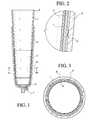
- FIG. 1is a vertical sectional view of a prosthesis system including a hard socket, an elastomer liner sleeve having a reinforcement material embedded in the liner sleeve body portion and further including a peripheral seal element integrated with the elastomer liner sleeve.
- FIG. 2is a sectional view corresponding to detail A in FIG. 1 .
- FIG. 3is a cross-sectional view taken along line III-III in FIG. 1 .
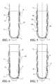
- FIGS. 4-10are vertical sectional views of a prosthesis system corresponding to FIG. 1 wherein alternate forms of peripheral seal elements are illustrated.
- FIGS. 11-16are sectional views corresponding respectively with sections B, C, D, E, F, and G of FIGS. 4 , 6 , 7 , 8 , 9 and 10 .
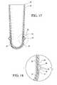
- FIG. 17is a vertical sectional view of an alternate form of an elastomer liner sleeve including a reinforcement material embedded in the liner sleeve body portion and a peripheral seal element secured to the elastomer liner sleeve in a recessed portion of the elastomer liner sleeve.
- FIG. 18is a sectional view corresponding to detail H in FIG. 17 .
- FIG. 19is a vertical sectional view of an alternate prosthesis system including the liner sleeve of FIG. 17 .
- FIG. 20is a sectional view corresponding to detail I in FIG. 19 .
- FIGS. 21-35are vertical sectional views of alternate forms of the peripheral seal element illustrated in FIG. 17 .
- FIG. 36is an elevational view of another embodiment of a prosthetic liner.
- FIG. 37is an elevational view of an embodiment of an embodiment of a sealing member.
- FIG. 38is a sectional view taken along line XXXVIII-XXXVIII in FIG. 37 .
- FIG. 39is a vertical sectional view of an alternate prosthesis system including the liner sleeve of FIG. 36 .
- FIG. 40is a sectional view corresponding to detail J in FIG. 39 .
- FIG. 41is a vertical sectional view of an alternate sealing member and prosthetic liner.
- FIG. 42is a sectional view corresponding to detail K in FIG. 41 .
- an elastomer liner sleeve body portion 1is formed as an elongate, generally conical member as is well known in the art and as is further described in U.S. Pat. No. 4,923,474, the entirety of which is incorporated herein by reference.
- the liner sleeve body portionmay be formed of various elastomer materials that are known to those skilled in the art and that are typically used for the manufacture of prosthetic liner sleeves.
- the liner sleeveextends between a proximal end 2 and a distal end area 3 .
- the liner sleeve body portionis soft and at least radially distensible elastically.
- the liner sleevealso may be elastically distensible axially or may have limited axial elasticity or at least a greater elastic stiffness (resistance to distension) in an axial sense as compared with its radial elasticity, but such anisotropy is optional.
- a reinforcement material 4is integrated into the elastomer of the liner sleeve body portion, for example in the manner described in U.S. Pat. No. 4,923,474.
- Various reinforcement materialsmay be utilized to limit axial distension of the liner sleeve body portion and typically a material that is axially stiff but radially compliant is preferred.
- the combination of the elastomer material constituting the liner sleeve body portion and the reinforcement body materialresults in a liner sleeve that resists elongation in the axial direction in the event that tension is applied to the liner sleeve material while the sleeve is fully radially compliant elastically so as not to unduly compress a residual limb contained within the liner sleeve or restrict its ability to fill the hard socket member.
- the reinforcement material 4alternatively may be located externally of the elastomer, such as a textile cover on the elastomer liner sleeve body, for example.
- the liner sleeve 1is typically donned on a residual limb and the limb and sleeve are then inserted into the prosthetic socket 5 which is typically rigid or hard in order to carry loads transferred from a prosthetic device attached to the socket to the residual limb and vice-versa.
- the softer elastomer of the liner sleeve body portionadheres to the skin of a residual limb frictionally to thereby secure the limb within the sleeve.
- the liner sleeveremains contained within the hard socket 5 after it has been fully inserted to the distal end area of the hard socket by effectively isolating the interior of the hard socket 5 from atmosphere.
- any pulling forces applied to the liner sleevewill result in a suction being created between the distal end of the liner sleeve and the interior of the hard socket at its distal end area.
- the increased stiffness in an axial sense created by the reinforcement materialminimizes pumping action on the residual limb and creates a stiffer interface between the residual limb and the liner sleeve in the area occupied by the reinforcement material.
- the reinforcement material 4extends over a limited distal end area of the liner sleeve, but could extend fully around the distal end area of the liner sleeve, if desired, as shown, for example, in U.S. Pat. No. 4,923,474, and up to the proximal end 2 of the liner sleeve.
- a seal element 6 associated with the liner sleeveis provided.
- the seal element 6could be formed of the same silicone material as the liner sleeve body portion 1 and created integrally in one piece with the liner sleeve body portion 1 during molding or forming of the liner sleeve body portion 1 , or, alternatively, could be formed separately of a softer or stiffer material or a material more suitable for a seal than the material forming the liner sleeve body portion, and then secured to the liner sleeve.
- the seal element 6may be tapered outwardly from its distal end towards its proximal end to facilitate insertion of the liner sleeve body portion 1 into the hard socket 5 and tends to resist outward movement of the liner sleeve from the hard socket. Also, the form of seal element 6 preferably provides an increased sealing force between the liner sleeve 1 and the hard socket 5 when the liner sleeve 1 is moved in a direction tending to withdraw it from the hard socket, or in other words, the seal element 6 seals more effectively in a direction towards the liner sleeve distal end when subjected to a pressure differential where a lower pressure exists towards the distal side of the seal as compared to the proximal side thereof.
- the seal element 6could be formed as a separate element or assembly of elements attached to or otherwise secured to the liner sleeve body portion 1 , as will be described below. It will be apparent that any manufacturing technique known to those skilled in the art could be utilized to create an enlarged seal element 6 surrounding the peripheral area of the liner sleeve body portion 1 at an area thereof between the proximal and distal end areas 2 , 3 of the liner sleeve body portion 1 so that, upon insertion of the liner sleeve body portion into a hard socket 5 , the seal 6 isolates the distal end area of the interior of the hard socket 5 from atmosphere between the seal 6 and the distal end area of the hard socket 5 . While a single seal element may be utilized in accordance with the present invention, a plurality of seal rings 6 secured to the liner sleeve could be utilized to provide enhanced sealing effect, as will be described below.
- the seal 6When the liner sleeve body portion 1 is fully inserted into the socket 5 , the seal 6 fully isolates the interior of the socket distal end area from atmosphere until communication is provided between the interior of the socket distal end and atmosphere.
- an appropriate one way valve element 7may be provided, or a valve capable of opening and closing manually may be used to isolate the interior of the distal end of the socket 5 from atmosphere.
- the presence of the reinforcement material in the vicinity of the seal 6further enhances the function of the seal element 6 in maintaining the distal end area of the socket 5 isolated from atmosphere when the residual limb and its associated liner sleeve body portion 1 have been fully inserted into the socket due to better distribution of loads between the socket 5 , the liner sleeve body portion, and a residual limb.
- a hypobaric pressurecould be created between the distal end area of the liner sleeve body portion 1 and the distal end of the socket 5 by attaching a pump or other device that enables evacuation of atmosphere between the seal 6 and the distal end of the socket 5 .
- liner sleeve body portion 8comprising an air-impermeable elastomeric material such as silicone is provided with a peripheral seal element 9 shown in more detail in FIG. 11 .
- the seal element 9is formed as a separate element from the liner sleeve body portion 8 and is securely attached thereto by appropriate bonding techniques that may include adhesive, heat seal, etc.
- the hard socket 5 ais provided with a slightly stepped portion 10 that enhances cooperation between the interior of the hard socket 5 a and the seal element 9 .
- the stepped portion 10is not required but is optional.
- the seal element 9includes a cantilevered end portion facing towards the proximal side of the liner sleeve body portion 8 to thereby enhance the ability of the seal element 9 to freely flex when a pressure differential exists on either side of the seal element 9 . It will be apparent that when a higher pressure exists on the proximal side of the seal element 9 as compared with the distal side thereof, the seal element 9 will tend to expand outwardly against the interior surface of the hard socket 5 a and a radial sealing force exerted by the seal will increase commensurately with the pressure differential.
- the properties of the seal and the interior wall of the hard socket 5 aare such that the amputee may readily withdraw the liner sleeve body portion 8 from the hard socket 5 a upon gentle pulling of the liner sleeve away from the hard socket, optionally while opening valve 7 to expose the isolated region 11 between the distal portion of the liner sleeve body portion 8 and the distal end area of the hard socket 5 a to atmosphere.
- liner sleeve body portion 12is provided with multiple, axially spaced seal elements 9 a corresponding to seal element 9 in FIG. 4 .
- Thisprovides enhanced sealing between the liner sleeve body portion 12 and the interior of the hard socket 5 b due to the multiple sealing surfaces provided and furthermore provides additional spaces 11 a that are isolated from atmosphere to thereby enhance the suction effect between the liner sleeve body portion 12 and the hard socket 5 b .
- the stepped portion 10 a of the hard socket interior wallis located at a more distal region of the hard socket as compared with the stepped portion 10 in FIG. 4 .
- liner sleeve body portion 13is provided with a single peripherally extending seal element 14 located towards the distal region of the liner sleeve body portion 13 .
- the seal element 14is formed separately from the liner sleeve body portion 13 and is secured thereto in the manner described above with respect to seal element 9 in FIG. 4 .
- a reinforcement material 4 as described above in the example shown in FIG. 1is provided to limit axial distension of the liner sleeve body portion 13 , the reinforcement material being located in the vicinity of the seal element 14 and extending in a proximal direction relative thereto within the liner sleeve body portion 13 .
- the seal element 14 and its relationship with the hard socket 5 c in this example, the liner sleeve body portion 13 and the reinforcement material 4are shown in more detail in FIG. 12 .
- liner sleeve body portion 15is provided with a seal assembly 16 which is shown in more detail in FIG. 13 .
- the sleeve element 16may be formed as a strip of material having radially bendable flaps constituting seal surfaces that, when exposed to differential pressure, will bend radially outwardly to engage the interior of the hard socket 5 , which may correspond in shape to the hard socket 5 illustrated in FIG. 1 .
- the seal element 16may be secured to the liner sleeve body portion 15 by bonding, heat sealing, or any other appropriate bonding technique that will be readily apparent to a person skilled in the art.
- liner sleeve body portion 17is provided with a peripheral seal element 16 which is similar to the seal element described in FIG. 13 , and a reinforcement material 4 is provided in the liner sleeve body portion 17 in a manner corresponding to that described previously with regard to FIG. 6 .
- liner sleeve body portion 18is provided with an integral peripherally extending seal element 19 that is shown in more detail in FIG. 15 .
- the seal element 19is integrally formed in one piece with the liner sleeve body portion 18 and comprises multiple sealing surfaces inclined radially outwardly and upwardly as shown in FIG. 15 .
- Each radially outwardly extending elementincludes a sealing surface that engages the interior wall of the hard socket 5 in a manner similar to that described previously in connection with the seal elements 9 , 9 a , 15 and 16 .
- a reinforcement material 4is provided in the liner sleeve body portion 18 in the vicinity of the peripheral seal 19 and extending proximally relative thereto.
- liner sleeve body portion 20is provided with a peripheral seal 21 corresponding to seal 19 described above in connection with FIG. 9 .
- a reinforcement materialis not provided in this example.
- the interior of the hard socket 5is not provided with a stepped portion in this example, although a stepped portion corresponding to the stepped portion 10 could be provided at the distal end area of the seal 21 when the liner sleeve body portion 20 is fully inserted in the hard socket 5 if desired.
- FIGS. 17-20an alternative preferred form of a liner sleeve and seal element is illustrated.
- liner sleeve body portion 22 having a proximal end 24 and a distal end area 26is provided with a recessed portion 28 and a peripheral seal element 30 radially protruding from the recessed portion 28 .
- the recessed portion 28extends continuously around a peripheral portion of the liner sleeve body portion 22 between the proximal and distal end areas 24 , 26 .
- the recessed portion 28 of the liner sleeve body portion 22is configured with a length, width and depth to accommodate compression of the seal element 30 .
- the liner sleeve body portion 22may include a reinforcement material 32 that extends substantially around the distal area 26 of the liner sleeve body portion 22 and preferably extends at least to the seal element 30 .
- the placement of the reinforcement material 32is not limited to the distal end area of the liner sleeve body portion, and may extend upwardly to the proximal end 24 of the liner sleeve body portion 22 .
- the seal element 30 of this embodimentis formed as a separate element from the liner sleeve body portion 22 , and is provided with a base member 34 that is positioned within the recessed portion 28 and is securely attached to the liner sleeve body portion 22 by appropriate bonding techniques that may include adhesive, heat seal, etc.
- the base member 34is preferably parallel to the outer periphery of the liner sleeve body portion; however it will be understood that it is not limited to this orientation.
- the seal element 30includes a radially outwardly pitched member 36 that extends from a proximal end of the base member 34 and is directed towards the proximal end 24 of the liner sleeve body portion 22 at an angle relative to the base member 34 .
- the seal element 30also includes a radially inwardly pitched member 38 that connects to a proximal end of the outwardly pitched member 36 , and is directed towards the proximal end 24 of the liner sleeve body portion 22 at an angle relative to the base member 34 .
- the liner sleeve body portion 22is shown as being donned on a residual limb and the limb and liner sleeve body portion are inserted into a prosthetic hard socket 40 .
- the hard socket 40includes a valve 7 located at a distal end area thereof that is of the type described above in the preceding embodiments of the present invention.
- the seal element 30is compressed so as to lie at least partially within the recessed portion 28 and bridges a seal between the liner sleeve body portion 22 and the hard socket 40 .
- the angles at which the outwardly and inwardly pitched members 36 , 38 of the seal element 30 extend relative to the base member 34are substantially less than when the liner sleeve body portion 22 is not inserted into the hard socket 40 .
- seal elementwhen compressed, at least a portion of the seal element should radially distend at least a distance from the recessed portion to sufficiently bridge the seal between the liner sleeve body portion and a hard socket.
- the recessed portion 28may have a depth with a dimension generally corresponding at least to the thickness of the base member 34 .
- the length of the recessed portionmay be configured so as to have a length that is less than the combined length of the base, outwardly and inwardly members so as to prevent the seal element from becoming completely flat when the sleeve liner is inserted into a hard socket.
- FIGS. 21-35alternative preferred forms of the seal element shown in FIGS. 17-20 are illustrated.
- the alternative seal elementsmay be positioned within the recessed portion of the liner sleeve body portion or along the exterior of the liner sleeve body portion.
- a seal element 42may have radially pitched members having different lengths, thicknesses and widths, extending at different angles relative to the base member, or may be connected to one another by a connecting member 44 generally parallel with the base member.
- the inwardly pitched membermay include at its proximal end an extension member 46 extending generally parallel with the base portion detached from the liner sleeve body portion, or in the alternative, may extend distally beyond the connection to the outwardly pitched member.
- distal portion 48 of the inwardly pitched membermay have a curved, straight, or a combination of curved and straight profiles.
- the outwardly pitched membermay also extend proximally beyond the connection to the inwardly pitched member and such proximal portion 50 thereof may have a curved, straight, or a combination of curved and straight profiles.
- the radially outwardly and inwardly pitched membersmay be replaced by a curved member 52 that extends from the base member of the seal element.
- Said curved membermay be defined as extending outwardly from the liner sleeve body portion to an apex and then extending inwardly towards the liner sleeve body portion a predetermined distance.
- the inwardly extending portion of the curved membermay extend a distance from the apex short of the outer periphery of the liner sleeve body portion.
- the curved membermay include at its proximal end an extension member 54 that is detached from the liner sleeve body portion and substantially parallel with the base portion.
- the seal elementmay include a tapered segment 56 that extends proximally from the base member and under an outwardly pitched member or curved member.
- the extension member 46may also include a tapered portion 56 distally extending under an inwardly pitched member or curved member of the seal element.
- a liner sleeve 110which includes two main sections, proximal section 112 , and distal section 114 .
- the proximal section 112comprises a textile having an inner surface that is coated with a silicone composition.
- the distal section 114comprises an outer surface that is a silicone composition.
- the distal sectionconsists a silicone composition.
- the distal sectioncomprises a textile that is coated on both its inner and outer surfaces with a silicone composition.
- the outer surface of the distal sectionmay be substantially smooth, and may have an inherent tackiness.
- the liner sleeve 110may include a reinforcement material that is associated with the liner sleeve and located over a length at least coinciding with the location of a sealing member 116 when fitted onto the liner sleeve 110 .
- the sealing member 116is provided that is separate from the liner sleeve 110 .
- the sealing member 116includes a seal element 118 provided at a proximal end area of the sealing member 116 .
- the sealing member 116also includes a receiving portion 120 located at the distal end area of the sealing member 116 .
- the seal element 118may have inwardly pitched members 124 , 126 which meet at peak 128 which forms a radially extending annular ring about the sealing member 116 .
- the seal element 118may have any configuration shown in FIGS. 17-35 .
- the seal element 118 of the sealing member 116may include a lip 122 extending from the receiving portion towards the proximal end of the sealing member 116 .
- the lip 122is adapted to extend generally parallel to the outer wall of the liner sleeve 110 .
- the receiving portion 120 of the sealing member 116is adapted to correspond to the shape of the distal end area of the liner sleeve 110 . As shown in FIGS. 37-38 , the receiving portion 120 is generally cup-shaped and spherical in nature, and the seal element 118 extends radially outwardly relative to the outer wall of the receiving portion 120 .
- the receiving portionis not limited to a cup-shaped configuration and any suitable configuration that will correspond to a distal end area of a liner sleeve may be used.
- the sealing member 116may be constructed from a variety of materials, such as polymers, rubbers, coated textiles and any other suitable material. According to the embodiment of FIGS. 36-39 , the sealing member 116 is constructed from a silicone composition such that along with the silicone outer surface of the liner sleeve 110 , the sealing member 116 and the liner sleeve 110 will frictionally fit with one another due to their inherent tackiness when they are contiguous.
- the sealing member 116is fitted onto the distal end area of the liner sleeve, air is expelled so as to enable the sealing member 116 to remain on the distal end area of the liner sleeve 110 , and form an air-tight seal at portions corresponding to the receiving portion 120 .
- the lip 122serves to divide the air-tight seal of the receiving portion 120 from the seal element 116 , so the seal element 116 can form an air-tight seal between the hard socket 132 and the liner sleeve 110 .
- the liner sleeve 110 and the sealing member 116form part of a prosthesis system that further includes the hard socket 132 having a one-way distal valve 134 .
- the combination of the liner sleeve 110 and sealing member 116conform to the shape of the internal socket wall, providing an airtight seal.
- airis expelled through the distal valve 134 , thereby creating hypobaric suction below the seal.
- the reinforcement material 130 of the liner sleeve 110is provided to prevent elongation of tissue of the residual limb fitted with the socket.
- the liner sleeve 136includes a recessed portion 138 that extends from a distal area of the liner sleeve to the distal end of the liner sleeve.
- the extent of the recessed portion 138is governed by the size of the sealing member 116 so that the seal element can be deflected into the recessed portion 138 , and so that the receiving portion 120 forms an air-tight seal over the recessed portion 138 below the region in which the seal element 118 may be deflected.
- the recessed portion 138is reinforced with reinforcement material 130 as in other embodiments described herein.
- the recessed portion 138may merely comprise an annular recess that does not form the entirety of the distal end area. An example of such a recessed portion may be found in the embodiment of FIG. 17 .
Landscapes
- Health & Medical Sciences (AREA)
- Cardiology (AREA)
- Oral & Maxillofacial Surgery (AREA)
- Transplantation (AREA)
- Engineering & Computer Science (AREA)
- Biomedical Technology (AREA)
- Heart & Thoracic Surgery (AREA)
- Vascular Medicine (AREA)
- Life Sciences & Earth Sciences (AREA)
- Animal Behavior & Ethology (AREA)
- General Health & Medical Sciences (AREA)
- Public Health (AREA)
- Veterinary Medicine (AREA)
- Prostheses (AREA)
Abstract
Description
Claims (17)
Priority Applications (1)
| Application Number | Priority Date | Filing Date | Title |
|---|---|---|---|
| US12/960,906US8052760B2 (en) | 2002-12-20 | 2010-12-06 | Suspension liner system with seal |
Applications Claiming Priority (5)
| Application Number | Priority Date | Filing Date | Title |
|---|---|---|---|
| US43466902P | 2002-12-20 | 2002-12-20 | |
| US10/690,545US7025793B2 (en) | 2002-12-20 | 2003-10-23 | Suspension liner with seal |
| US11/135,354US7749281B2 (en) | 2002-12-20 | 2005-05-24 | Suspension liner with seal |
| US11/516,500US7909884B2 (en) | 2002-12-20 | 2006-09-07 | Suspension liner system with seal |
| US12/960,906US8052760B2 (en) | 2002-12-20 | 2010-12-06 | Suspension liner system with seal |
Related Parent Applications (1)
| Application Number | Title | Priority Date | Filing Date |
|---|---|---|---|
| US11/516,500ContinuationUS7909884B2 (en) | 2002-12-20 | 2006-09-07 | Suspension liner system with seal |
Publications (2)
| Publication Number | Publication Date |
|---|---|
| US20110077748A1 US20110077748A1 (en) | 2011-03-31 |
| US8052760B2true US8052760B2 (en) | 2011-11-08 |
Family
ID=46326045
Family Applications (2)
| Application Number | Title | Priority Date | Filing Date |
|---|---|---|---|
| US11/516,500Active2026-03-05US7909884B2 (en) | 2002-12-20 | 2006-09-07 | Suspension liner system with seal |
| US12/960,906Expired - Fee RelatedUS8052760B2 (en) | 2002-12-20 | 2010-12-06 | Suspension liner system with seal |
Family Applications Before (1)
| Application Number | Title | Priority Date | Filing Date |
|---|---|---|---|
| US11/516,500Active2026-03-05US7909884B2 (en) | 2002-12-20 | 2006-09-07 | Suspension liner system with seal |
Country Status (1)
| Country | Link |
|---|---|
| US (2) | US7909884B2 (en) |
Cited By (56)
| Publication number | Priority date | Publication date | Assignee | Title |
|---|---|---|---|---|
| US8287477B1 (en) | 2003-09-25 | 2012-10-16 | Massachusetts Institute Of Technology | Active ankle foot orthosis |
| US8419804B2 (en) | 2008-09-04 | 2013-04-16 | Iwalk, Inc. | Hybrid terrain-adaptive lower-extremity systems |
| US8500823B2 (en) | 2005-03-31 | 2013-08-06 | Massachusetts Institute Of Technology | Powered artificial knee with agonist-antagonist actuation |
| US8512415B2 (en) | 2005-03-31 | 2013-08-20 | Massachusetts Institute Of Technology | Powered ankle-foot prothesis |
| US8551184B1 (en) | 2002-07-15 | 2013-10-08 | Iwalk, Inc. | Variable mechanical-impedance artificial legs |
| WO2013165909A1 (en) | 2012-04-30 | 2013-11-07 | Ossur Hf | Prosthetic device, system and method for increasing vacuum attachment |
| DE102012017214A1 (en) | 2012-08-31 | 2014-05-15 | Otto Bock Healthcare Gmbh | Prosthesis liner and prosthetic socket system with prosthetic liner and prosthetic socket |
| US8734528B2 (en) | 2005-03-31 | 2014-05-27 | Massachusetts Institute Of Technology | Artificial ankle-foot system with spring, variable-damping, and series-elastic actuator components |
| US20140257522A1 (en)* | 2002-12-20 | 2014-09-11 | Ossur Hf | Suspension liner system with seal |
| US8864846B2 (en) | 2005-03-31 | 2014-10-21 | Massachusetts Institute Of Technology | Model-based neuromechanical controller for a robotic leg |
| US8870967B2 (en) | 2005-03-31 | 2014-10-28 | Massachusetts Institute Of Technology | Artificial joints using agonist-antagonist actuators |
| WO2015041913A1 (en) | 2013-09-17 | 2015-03-26 | Ossur Hf | Silicone-based prosthetic and orthotic liners with antiperspirant and methods of forming the same |
| US9028558B2 (en) | 2009-11-17 | 2015-05-12 | Ossur Hf | Suspension liner having multiple component system |
| US9032635B2 (en) | 2011-12-15 | 2015-05-19 | Massachusetts Institute Of Technology | Physiological measurement device or wearable device interface simulator and method of use |
| US9060883B2 (en) | 2011-03-11 | 2015-06-23 | Iwalk, Inc. | Biomimetic joint actuators |
| WO2015108841A1 (en) | 2014-01-15 | 2015-07-23 | Ossur Hf | Bodysuit with sealing components |
| WO2015127337A1 (en) | 2014-02-21 | 2015-08-27 | Ossur Hf | Prosthetic socket system |
| US9198780B2 (en) | 2012-02-14 | 2015-12-01 | Ossur Hf | Vacuum assisted suspension system |
| US9221177B2 (en) | 2012-04-18 | 2015-12-29 | Massachusetts Institute Of Technology | Neuromuscular model-based sensing and control paradigm for a robotic leg |
| DE102014011374A1 (en) | 2014-08-05 | 2016-02-11 | Otto Bock Healthcare Gmbh | liner |
| US9333097B2 (en) | 2005-03-31 | 2016-05-10 | Massachusetts Institute Of Technology | Artificial human limbs and joints employing actuators, springs, and variable-damper elements |
| US9364348B2 (en) | 2013-03-01 | 2016-06-14 | Ossur Hf | Vacuum suspension system |
| US9498355B2 (en) | 2009-11-17 | 2016-11-22 | Ossur Hf | Suspension liner having multiple component system |
| US9566175B2 (en) | 2011-08-22 | 2017-02-14 | Ossur Hf | Suspension liner with seal component |
| US9603726B2 (en) | 2002-12-20 | 2017-03-28 | Ossur Hf | Adjustable seal system, seal component and method for using the same |
| US9664580B2 (en) | 2012-03-05 | 2017-05-30 | Otto Bock Healthcare Gmbh | Pressure indicating liner and method of use |
| US9687377B2 (en) | 2011-01-21 | 2017-06-27 | Bionx Medical Technologies, Inc. | Terrain adaptive powered joint orthosis |
| US9693883B2 (en) | 2010-04-05 | 2017-07-04 | Bionx Medical Technologies, Inc. | Controlling power in a prosthesis or orthosis based on predicted walking speed or surrogate for same |
| US9737419B2 (en) | 2011-11-02 | 2017-08-22 | Bionx Medical Technologies, Inc. | Biomimetic transfemoral prosthesis |
| US9757256B2 (en) | 2014-07-01 | 2017-09-12 | Ossur Hf | Pump mechanism for vacuum suspension system |
| US9839552B2 (en) | 2011-01-10 | 2017-12-12 | Bionx Medical Technologies, Inc. | Powered joint orthosis |
| US9925072B2 (en) | 2015-08-25 | 2018-03-27 | Ossur Iceland Ehf | Prosthetic system for removing fluid or sweat from inside of a liner with first and second independently sealed volumes |
| US9943421B2 (en) | 2015-05-21 | 2018-04-17 | Ossur Iceland Ehf | Membrane pump system for use with a prosthetic system |
| US10028845B2 (en) | 2015-01-08 | 2018-07-24 | Ossur Iceland Ehf | Pump mechanism |
| US10080672B2 (en) | 2005-03-31 | 2018-09-25 | Bionx Medical Technologies, Inc. | Hybrid terrain-adaptive lower-extremity systems |
| US10159585B2 (en) | 2016-04-25 | 2018-12-25 | Ossur Iceland Ehf | Prosthetic liner |
| US10179055B2 (en) | 2015-05-29 | 2019-01-15 | Ossur Iceland Ehf | Pump system for use with a prosthetic device |
| US10285828B2 (en) | 2008-09-04 | 2019-05-14 | Bionx Medical Technologies, Inc. | Implementing a stand-up sequence using a lower-extremity prosthesis or orthosis |
| US10307272B2 (en) | 2005-03-31 | 2019-06-04 | Massachusetts Institute Of Technology | Method for using a model-based controller for a robotic leg |
| US10322016B2 (en) | 2002-12-20 | 2019-06-18 | Ossur Iceland Ehf | Adjustable seal system, seal component and method for using the same |
| US10413429B2 (en) | 2015-08-27 | 2019-09-17 | Ossur Iceland Ehf | Pump system |
| US10420657B2 (en) | 2015-10-15 | 2019-09-24 | Ossur Iceland Ehf | Adjustable seal system |
| US10485681B2 (en) | 2005-03-31 | 2019-11-26 | Massachusetts Institute Of Technology | Exoskeletons for running and walking |
| US10512554B2 (en) | 2016-08-26 | 2019-12-24 | Ossur Iceland Ehf | Pump system |
| US10531965B2 (en) | 2012-06-12 | 2020-01-14 | Bionx Medical Technologies, Inc. | Prosthetic, orthotic or exoskeleton device |
| US10537449B2 (en) | 2011-01-12 | 2020-01-21 | Bionx Medical Technologies, Inc. | Controlling powered human augmentation devices |
| US20200060846A1 (en)* | 2017-04-26 | 2020-02-27 | Ottobock Se & Co. Kgaa | Liner system and method for applying a liner system |
| US10842653B2 (en) | 2007-09-19 | 2020-11-24 | Ability Dynamics, Llc | Vacuum system for a prosthetic foot |
| US10945865B2 (en) | 2017-11-01 | 2021-03-16 | Ossur Iceland Ehf | Prosthetic socket sealing system |
| US11090171B2 (en) | 2015-02-26 | 2021-08-17 | Romedis Gmbh | Apparatus, set and method for creating a plaster impression of a limb stump of a patient for manufacturing a prosthesis shaft and adaptor |
| US11116649B2 (en) | 2017-08-03 | 2021-09-14 | Nettwork Manufacturing, Inc. | Socket liner interface system |
| US11202716B2 (en) | 2017-10-20 | 2021-12-21 | Ossur Iceland Ehf | Heat and sweat management system |
| US11278433B2 (en) | 2005-03-31 | 2022-03-22 | Massachusetts Institute Of Technology | Powered ankle-foot prosthesis |
| US11298249B2 (en) | 2018-06-07 | 2022-04-12 | Ossur Iceland Ehf | Prosthetic interface |
| US11311393B2 (en) | 2017-08-06 | 2022-04-26 | Dbm, Llc | Universal digit |
| US11510793B2 (en) | 2017-11-28 | 2022-11-29 | Ossur Iceland Ehf | Adjustable seal system, seal component and method for using the same |
Families Citing this family (17)
| Publication number | Priority date | Publication date | Assignee | Title |
|---|---|---|---|---|
| US11523917B2 (en) | 2002-12-20 | 2022-12-13 | Ossur Hf | Suspension liner system with seal |
| US8343233B2 (en)* | 2005-09-24 | 2013-01-01 | Matt Perkins | Valve system for prosthetics |
| US9408724B2 (en) | 2005-09-24 | 2016-08-09 | Coyote Design And Manufacturing, Inc. | Air valve for external prosthesis |
| USD693926S1 (en) | 2006-09-25 | 2013-11-19 | Matt Perkins | Air valve |
| EP2170229A2 (en) | 2007-08-02 | 2010-04-07 | Össur HF | Liner for prosthetic and orthopedic systems |
| US8679194B2 (en) | 2009-01-21 | 2014-03-25 | Evolution Industries, Inc. | Expulsion liner for prosthetic or orthotic devices and associated methods |
| WO2010085336A1 (en) | 2009-01-21 | 2010-07-29 | Craig Mackenzie | Sealing sheath for prosthetic liner and related methods |
| US8123818B2 (en)* | 2009-03-27 | 2012-02-28 | Ossur Hf | Prosthetic liner with continuous distal end area |
| US8308816B2 (en)* | 2009-07-23 | 2012-11-13 | Prosthetic Design, Inc. | Sealing liner and lock for prosthetic limb |
| US8920518B2 (en)* | 2010-10-15 | 2014-12-30 | Evolution Industries, Inc. | Socket system including a vacuum liner for prosthetic or orthotic devices and associated methods |
| US20120150319A1 (en)* | 2010-12-14 | 2012-06-14 | Dallos Laszlo | Limb prosthesis with a sealing member between a liner and a socket |
| US9155636B1 (en) | 2011-06-01 | 2015-10-13 | Ray Fikes | Prosthetic socket liner |
| USD711510S1 (en) | 2013-03-01 | 2014-08-19 | Ossur Hf | Valve |
| US20160338858A1 (en)* | 2015-05-19 | 2016-11-24 | Lim Innovations, Inc. | Prosthetic socket liner garment |
| GB2554391B (en) | 2016-09-23 | 2019-09-11 | Blatchford Products Ltd | Prosthesis suspension liner sealing cap and prosthesis suspension system |
| WO2018187115A1 (en) | 2017-04-06 | 2018-10-11 | Ossur Iceland Ehf | Adjustable seal system, seal component and method for using the same |
| WO2019126119A1 (en) | 2017-12-20 | 2019-06-27 | Ossur Iceland Ehf | Liner having different regions of elongation |
Citations (72)
| Publication number | Priority date | Publication date | Assignee | Title |
|---|---|---|---|---|
| US980457A (en) | 1910-01-13 | 1911-01-03 | Justin Kay Toles | Artificial limb. |
| US1389824A (en) | 1920-04-07 | 1921-09-06 | Continsouza Sa Ets | Arpangement for registering images in cinematographic projecting apparatus |
| GB267988A (en) | 1925-09-18 | 1927-03-18 | Charles Albert Blatchford | Improvements in or connected with artificial limbs |
| US1893853A (en) | 1931-12-15 | 1933-01-10 | Amos E Tullis | Artificial limb |
| DE745981C (en) | 1940-09-21 | 1944-05-22 | Alois Geisen | Artificial leg with a sleeve to be attached to the leg stump by suction |
| US2530285A (en) | 1947-12-11 | 1950-11-14 | John G Catranis | Artificial leg |
| US2533404A (en) | 1948-08-13 | 1950-12-12 | Sharp Oscar | Artificial limb and valve therefor |
| DE813190C (en) | 1948-10-02 | 1951-09-10 | Franz Clouth | Suction prosthesis |
| US2634424A (en) | 1950-09-19 | 1953-04-14 | Thomas C O'gorman | Artificial leg |
| US2671225A (en) | 1951-11-05 | 1954-03-09 | Bardach Schoene Company Inc | Artificial limb stump socket |
| US2808593A (en) | 1956-02-07 | 1957-10-08 | Andersen Algot | Artificial limbs |
| US3393407A (en) | 1965-12-16 | 1968-07-23 | Edward J. Kandel | Artificial limb with end-bearing socket and method of making |
| DE2060239A1 (en) | 1970-12-08 | 1972-06-15 | Walter Dr Surerus | Support insert for artificial leg shanks |
| US3671980A (en) | 1971-02-19 | 1972-06-27 | Lincoln F Baird | Fluid pressure clamp for prosthetic appliance |
| DE2540138A1 (en) | 1975-09-09 | 1977-03-10 | Walter Dr Med Surerus | Annular liner for amputee stump - has detachable elastomer liner centred on screw adjustable support in prosthesis shaft |
| DE1795809B1 (en) | 1967-06-08 | 1977-12-22 | Merck Patent Gmbh | 2-METHYL-3-HYDROXY-4-HYDROXYMETHYL-5-ALKYL-MERCAPTOMETHYL-PYRIDINE |
| GB2069847A (en) | 1980-02-22 | 1981-09-03 | Blatchford & Sons Ltd | Artificial limb |
| GB2087727A (en) | 1980-10-14 | 1982-06-03 | Steeper Hugh Ltd | Manufacture of a prosthetics socket |
| DE3221920A1 (en) | 1982-06-11 | 1983-04-07 | Surerus, Walter, Dr., 7016 Gerlingen | Prosthesis stem |
| DE3508919A1 (en) | 1985-03-13 | 1986-09-18 | Surerus, Walter, Dr.Med., 7016 Gerlingen | Prosthetic shaft |
| US4923474A (en) | 1986-06-26 | 1990-05-08 | Ossur Hf | Sleeve-shaped article, particularly for amputation stumps |
| US5007937A (en) | 1988-03-31 | 1991-04-16 | New York University Medical Center | Structure for enhanced retention of artificial limbs and method of fabrication |
| US5139523A (en) | 1991-07-12 | 1992-08-18 | Paton Matthew T | Artificial limb socket apparatus |
| US5163965A (en) | 1991-07-29 | 1992-11-17 | Becker Orthopedic Appliance Company | Prosthetic attachment device and method |
| US5226918A (en) | 1992-07-13 | 1993-07-13 | Howard Silagy | Prosthesis with adjustable fitting clearance |
| US5314496A (en) | 1992-12-31 | 1994-05-24 | Harris Bertram H | Stump sock arrangement |
| US5376129A (en) | 1990-12-04 | 1994-12-27 | Board Of Regents, The University Of Texas System | Method and apparatus for making prosthetic socket preforms, prosthetic sockets, and socket attachment component |
| US5376131A (en)* | 1993-07-01 | 1994-12-27 | Manhasset Orthotics And Prosthetics, Ltd. | Suction socket for artificial limb |
| DE9419208U1 (en) | 1994-11-30 | 1995-01-26 | Carstens, Felix, 67433 Neustadt | Artificial link |
| US5387245A (en) | 1991-12-23 | 1995-02-07 | Fay; John N. | Inflatable prosthesis liner |
| JPH07155343A (en) | 1993-12-03 | 1995-06-20 | Nara Gishi:Kk | Mounting structure of artificial foot or artificial hand |
| US5549709A (en) | 1995-07-26 | 1996-08-27 | Caspers; Carl A. | Hypobarically-Controlled artificial limb for amputees |
| US5571208A (en)* | 1990-07-13 | 1996-11-05 | Caspers; Carl A. | Reinforced prosthetic polyurethane hypobaric sleeve |
| US5658353A (en) | 1995-10-31 | 1997-08-19 | Layton; Harry W. | Method for donning or doffing an artificial limb |
| WO1997034548A2 (en) | 1996-03-18 | 1997-09-25 | Haberman Louis J | Prosthesis liner for below-knee amputees |
| US5702489A (en) | 1995-08-18 | 1997-12-30 | Materials Engineering And Development, Inc. | Valve assembly for a prosthetic limb |
| US5718925A (en) | 1995-11-15 | 1998-02-17 | Ossur Hf. | Apparatus for making a prosthesis socket |
| US5728170A (en) | 1995-09-08 | 1998-03-17 | Otto Bock Orthopaedische Industrie Besitz- und Verwaltungs-Kommanditgesel lschaft | Below-knee prosthesis |
| US5735906A (en) | 1995-07-26 | 1998-04-07 | Caspers; Carl A. | Hypobarically-controlled artificial limb with detents for amputees |
| US5888230A (en)* | 1997-04-01 | 1999-03-30 | Helmy; Nashat N. | Modular liner for limb stump prosthesis |
| US5931872A (en) | 1995-01-11 | 1999-08-03 | Lohmann; Klaus H. | Prosthetic sock for reducing movement between residual limb and prosthesis and method for use |
| US6149691A (en) | 1998-06-26 | 2000-11-21 | Fay; John N. | Self-inflating socket having encased gel |
| WO2000074611A2 (en) | 1999-06-03 | 2000-12-14 | Caspers-Schneider Technologies,Inc. | Hypobarically-controlled socket for artificial limb |
| US6231617B1 (en) | 1999-07-14 | 2001-05-15 | John N. Fay | Prosthetic liner having longitudinal inelasticity |
| US20010005798A1 (en) | 1999-06-03 | 2001-06-28 | Caspers Carl A. | Vacuum apparatus and method for managing residual limb volume in an artificial limb |
| WO2001054631A1 (en) | 2000-01-27 | 2001-08-02 | Caspers-Schneider Technologies, Inc. Doing Business As Tec Interface Systems | Socket liner for artificial limb |
| US6273918B1 (en) | 1999-08-26 | 2001-08-14 | Jason R. Yuhasz | Magnetic detachment system for prosthetics |
| US20010016781A1 (en) | 1999-06-03 | 2001-08-23 | Caspers Carl A. | Osmotic membrane and vacuum system for artificial limb |
| US6287345B1 (en) | 1995-08-18 | 2001-09-11 | The Ohio Willow Wood Company | Valve assembly for a prosthetic limb |
| US6361568B1 (en) | 1999-02-09 | 2002-03-26 | Alps South Corporation | Prosthetic sleeve with air outlet valve |
| WO2002026158A2 (en) | 2000-09-27 | 2002-04-04 | Caspers Schneider Technologies | Socket liner for artificial limb |
| US20020040248A1 (en) | 2000-10-04 | 2002-04-04 | Karason Gudjon G. | Artificial limb socket containing volume control pad |
| US20020087215A1 (en) | 1999-06-03 | 2002-07-04 | Caspers Carl A. | Vacuum pump and shock absorber for artificial limb |
| US20020091449A1 (en) | 1999-06-03 | 2002-07-11 | Caspers Carl A. | Plate/socket attachment for artificial limb vacuum pump |
| US20020099450A1 (en) | 2000-04-25 | 2002-07-25 | Dean Robert C. | Dynamic variable geometry fitting system for use with a body appliance |
| WO2003024367A2 (en) | 2001-08-30 | 2003-03-27 | össur hf | Sealing assembly comprising lips for prosthetic shafts |
| WO2003024370A1 (en) | 2001-08-30 | 2003-03-27 | össur hf | Prosthesis shaft comprising a seal |
| WO2003039398A2 (en) | 2001-11-05 | 2003-05-15 | össur hf | Prosthesis shaft with seal at the distal end |
| US20030191539A1 (en) | 1999-06-03 | 2003-10-09 | Caspers Carl A. | Vacuum pump and shock absorber for artificial limb |
| WO2003099173A1 (en) | 2002-05-23 | 2003-12-04 | Otto Bock Healthcare Lp | Pulsating pressure chamber in a prosthetic limb |
| US20040030411A1 (en) | 1999-06-03 | 2004-02-12 | Caspers Carl A. | Pulsating pressure chamber and method for fluid management |
| US20040098136A1 (en) | 1999-06-03 | 2004-05-20 | Caspers Carl A. | Socket liner for artificial limb with permanent attachment to socket |
| US20040122528A1 (en) | 2002-12-20 | 2004-06-24 | Egilsson Egill Sveinbjorn | Suspension liner with seal |
| US20040167638A1 (en) | 2002-11-01 | 2004-08-26 | Caspers Carl A. | Pressure/temperature monitoring device for prosthetics |
| US20050101693A1 (en) | 2003-11-06 | 2005-05-12 | Ohio Willow Wood Company | Gel and cushioning devices |
| US6964688B1 (en) | 1996-07-31 | 2005-11-15 | Ohio Willow Wood Company | Tube sock-shaped covering |
| US20050267598A1 (en)* | 2004-05-28 | 2005-12-01 | Bjarnason Asmundur B | Prosthetic or orthotic sleeve having external surface peripheral profiles |
| US20060212128A1 (en)* | 2005-03-16 | 2006-09-21 | Jaems E. And Joyce E. Smith | Artificial limb assembly having microprocessor-controlled vacuum pump |
| US20070123998A1 (en)* | 2002-12-20 | 2007-05-31 | Egilsson Egill S | Suspension liner system with seal |
| US20080221705A1 (en)* | 2007-03-05 | 2008-09-11 | Scussel Sbj Systems, Llc | Vacuum assisted prosthetic sleeve and socket |
| US20080221706A1 (en)* | 2007-03-05 | 2008-09-11 | Scussel S.B.J. Systems, Llc | Vacuum assisted prosthetic sleeve and socket utilizing a double membrane liner |
| US20100249950A1 (en)* | 2007-11-13 | 2010-09-30 | Otto Bock Healthcare Gmbh | Liner for vacuum sockets, and use of the liner |
Family Cites Families (2)
| Publication number | Priority date | Publication date | Assignee | Title |
|---|---|---|---|---|
| TW444922U (en)* | 1994-09-29 | 2001-07-01 | Tokyo Electron Ltd | Heating device and the processing device using the same |
| IT1275654B1 (en)* | 1994-11-09 | 1997-10-17 | Riva Calzoni Spa | MODULAR STRUCTURE OF SUPPORT AND GUIDE FOR SLIDING RODS ESPECIALLY FOR SUBMARINE TURRETS. |
- 2006
- 2006-09-07USUS11/516,500patent/US7909884B2/enactiveActive
- 2010
- 2010-12-06USUS12/960,906patent/US8052760B2/ennot_activeExpired - Fee Related
Patent Citations (90)
| Publication number | Priority date | Publication date | Assignee | Title |
|---|---|---|---|---|
| US980457A (en) | 1910-01-13 | 1911-01-03 | Justin Kay Toles | Artificial limb. |
| US1389824A (en) | 1920-04-07 | 1921-09-06 | Continsouza Sa Ets | Arpangement for registering images in cinematographic projecting apparatus |
| GB267988A (en) | 1925-09-18 | 1927-03-18 | Charles Albert Blatchford | Improvements in or connected with artificial limbs |
| US1893853A (en) | 1931-12-15 | 1933-01-10 | Amos E Tullis | Artificial limb |
| DE745981C (en) | 1940-09-21 | 1944-05-22 | Alois Geisen | Artificial leg with a sleeve to be attached to the leg stump by suction |
| US2530285A (en) | 1947-12-11 | 1950-11-14 | John G Catranis | Artificial leg |
| US2533404A (en) | 1948-08-13 | 1950-12-12 | Sharp Oscar | Artificial limb and valve therefor |
| DE813190C (en) | 1948-10-02 | 1951-09-10 | Franz Clouth | Suction prosthesis |
| US2634424A (en) | 1950-09-19 | 1953-04-14 | Thomas C O'gorman | Artificial leg |
| US2671225A (en) | 1951-11-05 | 1954-03-09 | Bardach Schoene Company Inc | Artificial limb stump socket |
| US2808593A (en) | 1956-02-07 | 1957-10-08 | Andersen Algot | Artificial limbs |
| US3393407A (en) | 1965-12-16 | 1968-07-23 | Edward J. Kandel | Artificial limb with end-bearing socket and method of making |
| DE1795809B1 (en) | 1967-06-08 | 1977-12-22 | Merck Patent Gmbh | 2-METHYL-3-HYDROXY-4-HYDROXYMETHYL-5-ALKYL-MERCAPTOMETHYL-PYRIDINE |
| DE2060239A1 (en) | 1970-12-08 | 1972-06-15 | Walter Dr Surerus | Support insert for artificial leg shanks |
| US3671980A (en) | 1971-02-19 | 1972-06-27 | Lincoln F Baird | Fluid pressure clamp for prosthetic appliance |
| DE2540138A1 (en) | 1975-09-09 | 1977-03-10 | Walter Dr Med Surerus | Annular liner for amputee stump - has detachable elastomer liner centred on screw adjustable support in prosthesis shaft |
| GB2069847A (en) | 1980-02-22 | 1981-09-03 | Blatchford & Sons Ltd | Artificial limb |
| GB2087727A (en) | 1980-10-14 | 1982-06-03 | Steeper Hugh Ltd | Manufacture of a prosthetics socket |
| DE3221920A1 (en) | 1982-06-11 | 1983-04-07 | Surerus, Walter, Dr., 7016 Gerlingen | Prosthesis stem |
| DE3508919A1 (en) | 1985-03-13 | 1986-09-18 | Surerus, Walter, Dr.Med., 7016 Gerlingen | Prosthetic shaft |
| US4923474A (en) | 1986-06-26 | 1990-05-08 | Ossur Hf | Sleeve-shaped article, particularly for amputation stumps |
| US5007937A (en) | 1988-03-31 | 1991-04-16 | New York University Medical Center | Structure for enhanced retention of artificial limbs and method of fabrication |
| US5571208A (en)* | 1990-07-13 | 1996-11-05 | Caspers; Carl A. | Reinforced prosthetic polyurethane hypobaric sleeve |
| US5376129A (en) | 1990-12-04 | 1994-12-27 | Board Of Regents, The University Of Texas System | Method and apparatus for making prosthetic socket preforms, prosthetic sockets, and socket attachment component |
| US5139523A (en) | 1991-07-12 | 1992-08-18 | Paton Matthew T | Artificial limb socket apparatus |
| US5163965A (en) | 1991-07-29 | 1992-11-17 | Becker Orthopedic Appliance Company | Prosthetic attachment device and method |
| US5387245A (en) | 1991-12-23 | 1995-02-07 | Fay; John N. | Inflatable prosthesis liner |
| US5226918A (en) | 1992-07-13 | 1993-07-13 | Howard Silagy | Prosthesis with adjustable fitting clearance |
| US5314496A (en) | 1992-12-31 | 1994-05-24 | Harris Bertram H | Stump sock arrangement |
| EP0631765A1 (en) | 1993-07-01 | 1995-01-04 | Manhasset Orthotics and Prosthetics, Ltd. | A stump-receiving socket for an artificial limb |
| US5376131A (en)* | 1993-07-01 | 1994-12-27 | Manhasset Orthotics And Prosthetics, Ltd. | Suction socket for artificial limb |
| JPH07155343A (en) | 1993-12-03 | 1995-06-20 | Nara Gishi:Kk | Mounting structure of artificial foot or artificial hand |
| DE9419208U1 (en) | 1994-11-30 | 1995-01-26 | Carstens, Felix, 67433 Neustadt | Artificial link |
| US5931872A (en) | 1995-01-11 | 1999-08-03 | Lohmann; Klaus H. | Prosthetic sock for reducing movement between residual limb and prosthesis and method for use |
| US5549709A (en) | 1995-07-26 | 1996-08-27 | Caspers; Carl A. | Hypobarically-Controlled artificial limb for amputees |
| US5735906A (en) | 1995-07-26 | 1998-04-07 | Caspers; Carl A. | Hypobarically-controlled artificial limb with detents for amputees |
| US6287345B1 (en) | 1995-08-18 | 2001-09-11 | The Ohio Willow Wood Company | Valve assembly for a prosthetic limb |
| US5702489A (en) | 1995-08-18 | 1997-12-30 | Materials Engineering And Development, Inc. | Valve assembly for a prosthetic limb |
| US5728170A (en) | 1995-09-08 | 1998-03-17 | Otto Bock Orthopaedische Industrie Besitz- und Verwaltungs-Kommanditgesel lschaft | Below-knee prosthesis |
| US5658353A (en) | 1995-10-31 | 1997-08-19 | Layton; Harry W. | Method for donning or doffing an artificial limb |
| US5972036A (en) | 1995-11-15 | 1999-10-26 | Ossur Usa Inc. | Process and apparatus for making prosthesis socket and prosthesis socket made thereby |
| US5718925A (en) | 1995-11-15 | 1998-02-17 | Ossur Hf. | Apparatus for making a prosthesis socket |
| WO1997034548A2 (en) | 1996-03-18 | 1997-09-25 | Haberman Louis J | Prosthesis liner for below-knee amputees |
| US5888216A (en) | 1996-03-18 | 1999-03-30 | Haberman; Louis J. | Prosthesis liner for below-knee amputees |
| US5904722A (en) | 1996-06-11 | 1999-05-18 | Caspers; Carl A. | Hypobarically-controlled, double-socket artificial limb with mechanical interlock |
| US6964688B1 (en) | 1996-07-31 | 2005-11-15 | Ohio Willow Wood Company | Tube sock-shaped covering |
| US5888230A (en)* | 1997-04-01 | 1999-03-30 | Helmy; Nashat N. | Modular liner for limb stump prosthesis |
| US6231616B1 (en) | 1997-04-01 | 2001-05-15 | Nashat N. Helmy | Modular liner for limb stump prosthesis |
| US6149691A (en) | 1998-06-26 | 2000-11-21 | Fay; John N. | Self-inflating socket having encased gel |
| US6361568B1 (en) | 1999-02-09 | 2002-03-26 | Alps South Corporation | Prosthetic sleeve with air outlet valve |
| US20040143345A1 (en) | 1999-06-03 | 2004-07-22 | Barbara Caspers | Socket liner for artificial limb |
| US6554868B1 (en) | 1999-06-03 | 2003-04-29 | Carl A. Caspers | Vacuum pump and shock absorber for artificial limb |
| US20010016781A1 (en) | 1999-06-03 | 2001-08-23 | Caspers Carl A. | Osmotic membrane and vacuum system for artificial limb |
| US6645253B2 (en) | 1999-06-03 | 2003-11-11 | Carl A. Caspers | Vacuum pump and shock absorber for artificial limb |
| US20010005798A1 (en) | 1999-06-03 | 2001-06-28 | Caspers Carl A. | Vacuum apparatus and method for managing residual limb volume in an artificial limb |
| US20030191539A1 (en) | 1999-06-03 | 2003-10-09 | Caspers Carl A. | Vacuum pump and shock absorber for artificial limb |
| US20040181290A1 (en) | 1999-06-03 | 2004-09-16 | Otto Bock Healthcare Lp | Vacuum apparatus and method for managing residual limb volume in an artificial limb |
| US20020087215A1 (en) | 1999-06-03 | 2002-07-04 | Caspers Carl A. | Vacuum pump and shock absorber for artificial limb |
| US20020091449A1 (en) | 1999-06-03 | 2002-07-11 | Caspers Carl A. | Plate/socket attachment for artificial limb vacuum pump |
| US20040030411A1 (en) | 1999-06-03 | 2004-02-12 | Caspers Carl A. | Pulsating pressure chamber and method for fluid management |
| US6508842B1 (en) | 1999-06-03 | 2003-01-21 | Barbara J. Caspers | Socket liner for artificial limb |
| US6761742B2 (en) | 1999-06-03 | 2004-07-13 | Otto Bock Healthcare Lp | Vacuum pump and shock absorber for artificial limb |
| US20040098136A1 (en) | 1999-06-03 | 2004-05-20 | Caspers Carl A. | Socket liner for artificial limb with permanent attachment to socket |
| WO2000074611A2 (en) | 1999-06-03 | 2000-12-14 | Caspers-Schneider Technologies,Inc. | Hypobarically-controlled socket for artificial limb |
| US6726726B2 (en) | 1999-06-03 | 2004-04-27 | Otto Bock Healthcare Lp | Vacuum apparatus and method for managing residual limb volume in an artificial limb |
| US6231617B1 (en) | 1999-07-14 | 2001-05-15 | John N. Fay | Prosthetic liner having longitudinal inelasticity |
| US6273918B1 (en) | 1999-08-26 | 2001-08-14 | Jason R. Yuhasz | Magnetic detachment system for prosthetics |
| WO2001054631A1 (en) | 2000-01-27 | 2001-08-02 | Caspers-Schneider Technologies, Inc. Doing Business As Tec Interface Systems | Socket liner for artificial limb |
| US6585774B2 (en) | 2000-04-25 | 2003-07-01 | Simbex, Llc | Dynamic variable geometry fitting system for use with a body appliance |
| US20020099450A1 (en) | 2000-04-25 | 2002-07-25 | Dean Robert C. | Dynamic variable geometry fitting system for use with a body appliance |
| WO2002026158A2 (en) | 2000-09-27 | 2002-04-04 | Caspers Schneider Technologies | Socket liner for artificial limb |
| US20020040248A1 (en) | 2000-10-04 | 2002-04-04 | Karason Gudjon G. | Artificial limb socket containing volume control pad |
| US20040243252A1 (en) | 2001-08-30 | 2004-12-02 | Felix Carstens | Sealing arrangement comprising lips for prosthetic shafts |
| WO2003024370A1 (en) | 2001-08-30 | 2003-03-27 | össur hf | Prosthesis shaft comprising a seal |
| WO2003024367A2 (en) | 2001-08-30 | 2003-03-27 | össur hf | Sealing assembly comprising lips for prosthetic shafts |
| US20040236434A1 (en) | 2001-08-30 | 2004-11-25 | Felix Carstens | Prosthesis shaft comprising a seal |
| WO2003039398A2 (en) | 2001-11-05 | 2003-05-15 | össur hf | Prosthesis shaft with seal at the distal end |
| US20040243251A1 (en) | 2001-11-05 | 2004-12-02 | Felix Carstens | Prosthesis shaft with seal at the distal end |
| WO2003099173A1 (en) | 2002-05-23 | 2003-12-04 | Otto Bock Healthcare Lp | Pulsating pressure chamber in a prosthetic limb |
| US20040167638A1 (en) | 2002-11-01 | 2004-08-26 | Caspers Carl A. | Pressure/temperature monitoring device for prosthetics |
| US20100318196A1 (en)* | 2002-12-20 | 2010-12-16 | Egill Sveinbjorn Egilsson | Suspension liner with seal |
| US20040122528A1 (en) | 2002-12-20 | 2004-06-24 | Egilsson Egill Sveinbjorn | Suspension liner with seal |
| US20070123998A1 (en)* | 2002-12-20 | 2007-05-31 | Egilsson Egill S | Suspension liner system with seal |
| US20050101693A1 (en) | 2003-11-06 | 2005-05-12 | Ohio Willow Wood Company | Gel and cushioning devices |
| US20050267598A1 (en)* | 2004-05-28 | 2005-12-01 | Bjarnason Asmundur B | Prosthetic or orthotic sleeve having external surface peripheral profiles |
| US7118602B2 (en)* | 2004-05-28 | 2006-10-10 | Ossur Hf | Suspension liner having external surface peripheral profiles |
| US20060212128A1 (en)* | 2005-03-16 | 2006-09-21 | Jaems E. And Joyce E. Smith | Artificial limb assembly having microprocessor-controlled vacuum pump |
| US20080221706A1 (en)* | 2007-03-05 | 2008-09-11 | Scussel S.B.J. Systems, Llc | Vacuum assisted prosthetic sleeve and socket utilizing a double membrane liner |
| US20080221705A1 (en)* | 2007-03-05 | 2008-09-11 | Scussel Sbj Systems, Llc | Vacuum assisted prosthetic sleeve and socket |
| US20100249950A1 (en)* | 2007-11-13 | 2010-09-30 | Otto Bock Healthcare Gmbh | Liner for vacuum sockets, and use of the liner |
Non-Patent Citations (2)
| Title |
|---|
| EP O3 78 9861-Supplementary European Search Report. |
| EP O3 78 9861—Supplementary European Search Report. |
Cited By (115)
| Publication number | Priority date | Publication date | Assignee | Title |
|---|---|---|---|---|
| US8551184B1 (en) | 2002-07-15 | 2013-10-08 | Iwalk, Inc. | Variable mechanical-impedance artificial legs |
| US9295567B2 (en)* | 2002-12-20 | 2016-03-29 | Ossur Hf | Suspension liner system with seal |
| US10342682B2 (en) | 2002-12-20 | 2019-07-09 | Ossur Hf | Suspension liner system with seal |
| US9707106B2 (en) | 2002-12-20 | 2017-07-18 | Ossur Hf | Adjustable seal system, seal component and method for using the same |
| US10828179B2 (en) | 2002-12-20 | 2020-11-10 | Ossur Iceland Ehf | Adjustable seal system, seal component and method for using the same |
| US10898352B2 (en) | 2002-12-20 | 2021-01-26 | Ossur Hf | Suspension liner system with seal |
| US9603726B2 (en) | 2002-12-20 | 2017-03-28 | Ossur Hf | Adjustable seal system, seal component and method for using the same |
| US9877851B2 (en) | 2002-12-20 | 2018-01-30 | Ossur Hf | Adjustable seal system, seal component and method for using the same |
| US20140257522A1 (en)* | 2002-12-20 | 2014-09-11 | Ossur Hf | Suspension liner system with seal |
| US10322016B2 (en) | 2002-12-20 | 2019-06-18 | Ossur Iceland Ehf | Adjustable seal system, seal component and method for using the same |
| US8808214B2 (en) | 2003-09-25 | 2014-08-19 | Massachusetts Institute Of Technology | Active ankle foot orthosis |
| US8551029B1 (en) | 2003-09-25 | 2013-10-08 | Massachusetts Institute Of Technology | Active ankle foot orthosis |
| US8376971B1 (en) | 2003-09-25 | 2013-02-19 | Massachusetts Institute Of Technology | Active ankle foot orthosis |
| US8287477B1 (en) | 2003-09-25 | 2012-10-16 | Massachusetts Institute Of Technology | Active ankle foot orthosis |
| US10695256B2 (en) | 2003-09-25 | 2020-06-30 | Massachusetts Institute Of Technology | Motorized limb assistance device |
| US9668888B2 (en) | 2003-09-25 | 2017-06-06 | Massachusetts Institute Of Technology | Active ankle foot orthosis |
| US8870967B2 (en) | 2005-03-31 | 2014-10-28 | Massachusetts Institute Of Technology | Artificial joints using agonist-antagonist actuators |
| US8500823B2 (en) | 2005-03-31 | 2013-08-06 | Massachusetts Institute Of Technology | Powered artificial knee with agonist-antagonist actuation |
| US10080672B2 (en) | 2005-03-31 | 2018-09-25 | Bionx Medical Technologies, Inc. | Hybrid terrain-adaptive lower-extremity systems |
| US10137011B2 (en) | 2005-03-31 | 2018-11-27 | Massachusetts Institute Of Technology | Powered ankle-foot prosthesis |
| US11273060B2 (en) | 2005-03-31 | 2022-03-15 | Massachusetts Institute Of Technology | Artificial ankle-foot system with spring, variable-damping, and series-elastic actuator components |
| US10307272B2 (en) | 2005-03-31 | 2019-06-04 | Massachusetts Institute Of Technology | Method for using a model-based controller for a robotic leg |
| US9149370B2 (en) | 2005-03-31 | 2015-10-06 | Massachusetts Institute Of Technology | Powered artificial knee with agonist-antagonist actuation |
| US8512415B2 (en) | 2005-03-31 | 2013-08-20 | Massachusetts Institute Of Technology | Powered ankle-foot prothesis |
| US11491032B2 (en) | 2005-03-31 | 2022-11-08 | Massachusetts Institute Of Technology | Artificial joints using agonist-antagonist actuators |
| US10588759B2 (en) | 2005-03-31 | 2020-03-17 | Massachusetts Institute Of Technology | Artificial human limbs and joints employing actuators, springs and variable-damper elements |
| US11278433B2 (en) | 2005-03-31 | 2022-03-22 | Massachusetts Institute Of Technology | Powered ankle-foot prosthesis |
| US8864846B2 (en) | 2005-03-31 | 2014-10-21 | Massachusetts Institute Of Technology | Model-based neuromechanical controller for a robotic leg |
| US9333097B2 (en) | 2005-03-31 | 2016-05-10 | Massachusetts Institute Of Technology | Artificial human limbs and joints employing actuators, springs, and variable-damper elements |
| US9339397B2 (en) | 2005-03-31 | 2016-05-17 | Massachusetts Institute Of Technology | Artificial ankle-foot system with spring, variable-damping, and series-elastic actuator components |
| US8734528B2 (en) | 2005-03-31 | 2014-05-27 | Massachusetts Institute Of Technology | Artificial ankle-foot system with spring, variable-damping, and series-elastic actuator components |
| US10342681B2 (en) | 2005-03-31 | 2019-07-09 | Massachusetts Institute Of Technology | Artificial ankle-foot system with spring, variable-damping, and series-elastic actuator components |
| US10485681B2 (en) | 2005-03-31 | 2019-11-26 | Massachusetts Institute Of Technology | Exoskeletons for running and walking |
| US9539117B2 (en) | 2005-03-31 | 2017-01-10 | Massachusetts Institute Of Technology | Method for controlling a robotic limb joint |
| US10842653B2 (en) | 2007-09-19 | 2020-11-24 | Ability Dynamics, Llc | Vacuum system for a prosthetic foot |
| US9211201B2 (en) | 2008-09-04 | 2015-12-15 | Iwalk, Inc. | Hybrid terrain-adaptive lower-extremity systems |
| US8419804B2 (en) | 2008-09-04 | 2013-04-16 | Iwalk, Inc. | Hybrid terrain-adaptive lower-extremity systems |
| US9351856B2 (en) | 2008-09-04 | 2016-05-31 | Iwalk, Inc. | Hybrid terrain-adaptive lower-extremity systems |
| US9345592B2 (en) | 2008-09-04 | 2016-05-24 | Bionx Medical Technologies, Inc. | Hybrid terrain-adaptive lower-extremity systems |
| US10105244B2 (en) | 2008-09-04 | 2018-10-23 | Bionx Medical Technologies, Inc. | Hybrid terrain-adaptive lower-extremity systems |
| US10285828B2 (en) | 2008-09-04 | 2019-05-14 | Bionx Medical Technologies, Inc. | Implementing a stand-up sequence using a lower-extremity prosthesis or orthosis |
| US10070974B2 (en) | 2008-09-04 | 2018-09-11 | Bionx Medical Technologies, Inc. | Hybrid terrain-adaptive lower-extremity systems |
| US9554922B2 (en) | 2008-09-04 | 2017-01-31 | Bionx Medical Technologies, Inc. | Hybrid terrain-adaptive lower-extremity systems |
| US8900325B2 (en) | 2008-09-04 | 2014-12-02 | Iwalk, Inc. | Hybrid terrain-adaptive lower-extremity systems |
| US9028558B2 (en) | 2009-11-17 | 2015-05-12 | Ossur Hf | Suspension liner having multiple component system |
| US9498355B2 (en) | 2009-11-17 | 2016-11-22 | Ossur Hf | Suspension liner having multiple component system |
| US9788977B2 (en) | 2009-11-17 | 2017-10-17 | Ossur Hf | Suspension liner having multiple component system |
| US9693883B2 (en) | 2010-04-05 | 2017-07-04 | Bionx Medical Technologies, Inc. | Controlling power in a prosthesis or orthosis based on predicted walking speed or surrogate for same |
| US10406002B2 (en) | 2010-04-05 | 2019-09-10 | Bionx Medical Technologies, Inc. | Controlling torque in a prosthesis or orthosis based on a deflection of series elastic element |
| US9839552B2 (en) | 2011-01-10 | 2017-12-12 | Bionx Medical Technologies, Inc. | Powered joint orthosis |
| US10537449B2 (en) | 2011-01-12 | 2020-01-21 | Bionx Medical Technologies, Inc. | Controlling powered human augmentation devices |
| US9687377B2 (en) | 2011-01-21 | 2017-06-27 | Bionx Medical Technologies, Inc. | Terrain adaptive powered joint orthosis |
| US9872782B2 (en) | 2011-03-11 | 2018-01-23 | Bionx Medical Technologies, Inc. | Biomimetic joint actuators |
| US9060883B2 (en) | 2011-03-11 | 2015-06-23 | Iwalk, Inc. | Biomimetic joint actuators |
| US10660768B2 (en) | 2011-08-22 | 2020-05-26 | Ossur Hf | Suspension liner with seal component |
| US9566175B2 (en) | 2011-08-22 | 2017-02-14 | Ossur Hf | Suspension liner with seal component |
| US10213325B2 (en) | 2011-08-22 | 2019-02-26 | Ossur Hf | Suspension liner with seal component |
| US11399968B2 (en) | 2011-08-22 | 2022-08-02 | Ossur Hf | Suspension liner with seal component |
| US9737419B2 (en) | 2011-11-02 | 2017-08-22 | Bionx Medical Technologies, Inc. | Biomimetic transfemoral prosthesis |
| US9032635B2 (en) | 2011-12-15 | 2015-05-19 | Massachusetts Institute Of Technology | Physiological measurement device or wearable device interface simulator and method of use |
| US10617537B2 (en) | 2012-02-14 | 2020-04-14 | Ossur Hf | Vacuum assisted suspension system |
| US9198780B2 (en) | 2012-02-14 | 2015-12-01 | Ossur Hf | Vacuum assisted suspension system |
| US9889025B2 (en) | 2012-02-14 | 2018-02-13 | Ossur Hf | Vacuum assisted suspension system |
| US9664580B2 (en) | 2012-03-05 | 2017-05-30 | Otto Bock Healthcare Gmbh | Pressure indicating liner and method of use |
| US9221177B2 (en) | 2012-04-18 | 2015-12-29 | Massachusetts Institute Of Technology | Neuromuscular model-based sensing and control paradigm for a robotic leg |
| US9975249B2 (en) | 2012-04-18 | 2018-05-22 | Massachusetts Institute Of Technology | Neuromuscular model-based sensing and control paradigm for a robotic leg |
| US11141294B2 (en) | 2012-04-30 | 2021-10-12 | Ossur Hf | Prosthetic device, system and method for increasing vacuum attachment |
| US11058561B2 (en) | 2012-04-30 | 2021-07-13 | Ossur Hf | Prosthetic device, system and method for increasing vacuum attachment |
| WO2013165909A1 (en) | 2012-04-30 | 2013-11-07 | Ossur Hf | Prosthetic device, system and method for increasing vacuum attachment |
| US9615946B2 (en) | 2012-04-30 | 2017-04-11 | Ossur Hf | Prosthetic device, system and method for increasing vacuum attachment |
| US10369018B2 (en) | 2012-04-30 | 2019-08-06 | Ossur Hf | Prosthetic device, system and method for increasing vacuum attachment |
| US9486335B2 (en) | 2012-04-30 | 2016-11-08 | Ossur Hf | Prosthetic device, system and method for increasing vacuum attachment |
| US9072617B2 (en) | 2012-04-30 | 2015-07-07 | Ossur Hf | Prosthetic device, system and method for increasing vacuum attachment |
| US10531965B2 (en) | 2012-06-12 | 2020-01-14 | Bionx Medical Technologies, Inc. | Prosthetic, orthotic or exoskeleton device |
| US9968469B2 (en) | 2012-08-31 | 2018-05-15 | Otto Bock Healthcare Gmbh | Prosthesis liner with suction cup and vacuum lock mechanism |
| DE102012017214A1 (en) | 2012-08-31 | 2014-05-15 | Otto Bock Healthcare Gmbh | Prosthesis liner and prosthetic socket system with prosthetic liner and prosthetic socket |
| US9820873B2 (en) | 2013-03-01 | 2017-11-21 | Ossur Hf | Vacuum suspension system |
| US9364348B2 (en) | 2013-03-01 | 2016-06-14 | Ossur Hf | Vacuum suspension system |
| WO2015041913A1 (en) | 2013-09-17 | 2015-03-26 | Ossur Hf | Silicone-based prosthetic and orthotic liners with antiperspirant and methods of forming the same |
| WO2015108841A1 (en) | 2014-01-15 | 2015-07-23 | Ossur Hf | Bodysuit with sealing components |
| US9993357B2 (en) | 2014-02-21 | 2018-06-12 | Ossur Hf | Prosthetic socket system |
| WO2015127337A1 (en) | 2014-02-21 | 2015-08-27 | Ossur Hf | Prosthetic socket system |
| US9757256B2 (en) | 2014-07-01 | 2017-09-12 | Ossur Hf | Pump mechanism for vacuum suspension system |
| US10729568B2 (en) | 2014-07-01 | 2020-08-04 | Ossur Hf | Pump mechanism for vacuum suspension system |
| DE102014011374A1 (en) | 2014-08-05 | 2016-02-11 | Otto Bock Healthcare Gmbh | liner |
| US11679012B2 (en) | 2015-01-08 | 2023-06-20 | Ossur Iceland Ehf | Pump mechanism |
| US10695198B2 (en) | 2015-01-08 | 2020-06-30 | Ossur Iceland Ehf | Pump mechanism |
| US10028845B2 (en) | 2015-01-08 | 2018-07-24 | Ossur Iceland Ehf | Pump mechanism |
| US11090171B2 (en) | 2015-02-26 | 2021-08-17 | Romedis Gmbh | Apparatus, set and method for creating a plaster impression of a limb stump of a patient for manufacturing a prosthesis shaft and adaptor |
| US10561508B2 (en) | 2015-05-21 | 2020-02-18 | Ossur Iceland Ehf | Vacuum pump system with heel pump for a prosthetic leg |
| US9943421B2 (en) | 2015-05-21 | 2018-04-17 | Ossur Iceland Ehf | Membrane pump system for use with a prosthetic system |
| US11246725B2 (en) | 2015-05-21 | 2022-02-15 | Ossur Iceland Ehf | Pump system |
| US10179055B2 (en) | 2015-05-29 | 2019-01-15 | Ossur Iceland Ehf | Pump system for use with a prosthetic device |
| US10624767B2 (en) | 2015-08-25 | 2020-04-21 | Ossur Iceland Ehf | Prosthetic system for sweat management |
| US9925072B2 (en) | 2015-08-25 | 2018-03-27 | Ossur Iceland Ehf | Prosthetic system for removing fluid or sweat from inside of a liner with first and second independently sealed volumes |
| US10413429B2 (en) | 2015-08-27 | 2019-09-17 | Ossur Iceland Ehf | Pump system |
| US11357647B2 (en) | 2015-08-27 | 2022-06-14 | Ossur Iceland Ehf | Pump system |
| US12220329B2 (en) | 2015-08-27 | 2025-02-11 | Ossur Iceland Ehf | Pump system |
| US11844709B2 (en) | 2015-10-15 | 2023-12-19 | Ossur Iceland Ehf | Adjustable seal system |
| US10420657B2 (en) | 2015-10-15 | 2019-09-24 | Ossur Iceland Ehf | Adjustable seal system |
| US12167974B2 (en) | 2016-04-25 | 2024-12-17 | Ossur Iceland Ehf | Prosthetic liner |
| US10159585B2 (en) | 2016-04-25 | 2018-12-25 | Ossur Iceland Ehf | Prosthetic liner |
| US11123203B2 (en) | 2016-04-25 | 2021-09-21 | Ossur Iceland Ehf | Prosthetic liner |
| US11376139B2 (en) | 2016-08-26 | 2022-07-05 | Ossur Iceland Ehf | Pump system |
| US10512554B2 (en) | 2016-08-26 | 2019-12-24 | Ossur Iceland Ehf | Pump system |
| US12004972B2 (en) | 2016-08-26 | 2024-06-11 | Ossur Iceland Ehf | Pump system |
| US20200060846A1 (en)* | 2017-04-26 | 2020-02-27 | Ottobock Se & Co. Kgaa | Liner system and method for applying a liner system |
| US12232986B2 (en)* | 2017-04-26 | 2025-02-25 | Ottobock Se & Co. Kgaa | Liner system and method for applying a liner system |
| US11116649B2 (en) | 2017-08-03 | 2021-09-14 | Nettwork Manufacturing, Inc. | Socket liner interface system |
| US11311393B2 (en) | 2017-08-06 | 2022-04-26 | Dbm, Llc | Universal digit |
| US11202716B2 (en) | 2017-10-20 | 2021-12-21 | Ossur Iceland Ehf | Heat and sweat management system |
| US10945865B2 (en) | 2017-11-01 | 2021-03-16 | Ossur Iceland Ehf | Prosthetic socket sealing system |
| US11510793B2 (en) | 2017-11-28 | 2022-11-29 | Ossur Iceland Ehf | Adjustable seal system, seal component and method for using the same |
| US11298249B2 (en) | 2018-06-07 | 2022-04-12 | Ossur Iceland Ehf | Prosthetic interface |
| US12036137B2 (en) | 2018-06-07 | 2024-07-16 | Ossur Iceland Ehf | Prosthetic interface |
Also Published As
| Publication number | Publication date |
|---|---|
| US20070005149A1 (en) | 2007-01-04 |
| US20110077748A1 (en) | 2011-03-31 |
| US7909884B2 (en) | 2011-03-22 |
Similar Documents
| Publication | Publication Date | Title |
|---|---|---|
| US8052760B2 (en) | Suspension liner system with seal | |
| US10898352B2 (en) | Suspension liner system with seal | |
| US7749281B2 (en) | Suspension liner with seal | |
| US9877851B2 (en) | Adjustable seal system, seal component and method for using the same | |
| US7169188B2 (en) | Sealing sleeve for sealing residual limb in a prosthetic socket | |
| US8679194B2 (en) | Expulsion liner for prosthetic or orthotic devices and associated methods | |
| US20210361448A1 (en) | Suspension liner system with seal |
Legal Events
| Date | Code | Title | Description |
|---|---|---|---|
| AS | Assignment | Owner name:ARION BANK HF, ICELAND Free format text:SECURITY AGREEMENT;ASSIGNOR:OSSUR HF;REEL/FRAME:025445/0539 Effective date:20080630 Owner name:OSSUR HF, ICELAND Free format text:ASSIGNMENT OF ASSIGNORS INTEREST;ASSIGNORS:EGILSSON, EGILL SVEINBJORN;ASGEIRSSON, SIGURDUR;SIGNING DATES FROM 20060831 TO 20060901;REEL/FRAME:025456/0392 | |
| AS | Assignment | Owner name:OSSUR HF, ICELAND Free format text:RELEASE BY SECURED PARTY;ASSIGNOR:ARION BANK HF;REEL/FRAME:026173/0297 Effective date:20110311 | |
| ZAAA | Notice of allowance and fees due | Free format text:ORIGINAL CODE: NOA | |
| ZAAB | Notice of allowance mailed | Free format text:ORIGINAL CODE: MN/=. | |
| STCF | Information on status: patent grant | Free format text:PATENTED CASE | |
| CC | Certificate of correction | ||
| CC | Certificate of correction | ||
| CC | Certificate of correction | ||
| FPAY | Fee payment | Year of fee payment:4 | |
| MAFP | Maintenance fee payment | Free format text:PAYMENT OF MAINTENANCE FEE, 8TH YEAR, LARGE ENTITY (ORIGINAL EVENT CODE: M1552); ENTITY STATUS OF PATENT OWNER: LARGE ENTITY Year of fee payment:8 | |
| FEPP | Fee payment procedure | Free format text:MAINTENANCE FEE REMINDER MAILED (ORIGINAL EVENT CODE: REM.); ENTITY STATUS OF PATENT OWNER: LARGE ENTITY | |
| LAPS | Lapse for failure to pay maintenance fees | Free format text:PATENT EXPIRED FOR FAILURE TO PAY MAINTENANCE FEES (ORIGINAL EVENT CODE: EXP.); ENTITY STATUS OF PATENT OWNER: LARGE ENTITY | |
| STCH | Information on status: patent discontinuation | Free format text:PATENT EXPIRED DUE TO NONPAYMENT OF MAINTENANCE FEES UNDER 37 CFR 1.362 | |
| FP | Lapsed due to failure to pay maintenance fee | Effective date:20231108 |