US8052702B2 - Vessel harvesting retractor with bilateral electrosurgical ligation - Google Patents
Vessel harvesting retractor with bilateral electrosurgical ligationDownload PDFInfo
- Publication number
- US8052702B2 US8052702B2US10/816,024US81602404AUS8052702B2US 8052702 B2US8052702 B2US 8052702B2US 81602404 AUS81602404 AUS 81602404AUS 8052702 B2US8052702 B2US 8052702B2
- Authority
- US
- United States
- Prior art keywords
- vessel
- harvesting device
- vessel harvesting
- electrodes
- endoscopic
- Prior art date
- Legal status (The legal status is an assumption and is not a legal conclusion. Google has not performed a legal analysis and makes no representation as to the accuracy of the status listed.)
- Expired - Fee Related, expires
Links
- 238000003306harvestingMethods0.000titleclaimsabstractdescription56
- 230000002146bilateral effectEffects0.000title1
- 238000002224dissectionMethods0.000claimsabstractdescription27
- 230000006835compressionEffects0.000claimsdescription9
- 238000007906compressionMethods0.000claimsdescription9
- 230000037361pathwayEffects0.000claims1
- 238000000034methodMethods0.000abstractdescription27
- 210000004204blood vesselAnatomy0.000abstractdescription3
- 210000003752saphenous veinAnatomy0.000description16
- 238000003780insertionMethods0.000description9
- 230000037431insertionEffects0.000description9
- 230000015271coagulationEffects0.000description4
- 238000005345coagulationMethods0.000description4
- 229920003023plasticPolymers0.000description4
- 210000003462veinAnatomy0.000description4
- 239000004033plasticSubstances0.000description3
- 238000000576coating methodMethods0.000description2
- 238000012986modificationMethods0.000description2
- 230000004048modificationEffects0.000description2
- 238000013519translationMethods0.000description2
- 208000012260Accidental injuryDiseases0.000description1
- 210000001015abdomenAnatomy0.000description1
- 210000001367arteryAnatomy0.000description1
- 239000011248coating agentSubstances0.000description1
- 239000012141concentrateSubstances0.000description1
- 239000004020conductorSubstances0.000description1
- 238000010276constructionMethods0.000description1
- 210000002815epigastric arteryAnatomy0.000description1
- 208000014674injuryDiseases0.000description1
- 239000002184metalSubstances0.000description1
- 239000004417polycarbonateSubstances0.000description1
- 229920000515polycarbonatePolymers0.000description1
- 210000002321radial arteryAnatomy0.000description1
- 229910001220stainless steelInorganic materials0.000description1
- 239000010935stainless steelSubstances0.000description1
- 238000001356surgical procedureMethods0.000description1
- 230000001960triggered effectEffects0.000description1
- 238000012800visualizationMethods0.000description1
- 238000003466weldingMethods0.000description1
Images


Classifications
- A—HUMAN NECESSITIES
- A61—MEDICAL OR VETERINARY SCIENCE; HYGIENE
- A61B—DIAGNOSIS; SURGERY; IDENTIFICATION
- A61B17/00—Surgical instruments, devices or methods
- A61B17/00008—Vein tendon strippers
- A—HUMAN NECESSITIES
- A61—MEDICAL OR VETERINARY SCIENCE; HYGIENE
- A61B—DIAGNOSIS; SURGERY; IDENTIFICATION
- A61B17/00—Surgical instruments, devices or methods
- A61B17/32—Surgical cutting instruments
- A—HUMAN NECESSITIES
- A61—MEDICAL OR VETERINARY SCIENCE; HYGIENE
- A61B—DIAGNOSIS; SURGERY; IDENTIFICATION
- A61B18/00—Surgical instruments, devices or methods for transferring non-mechanical forms of energy to or from the body
- A61B18/04—Surgical instruments, devices or methods for transferring non-mechanical forms of energy to or from the body by heating
- A61B18/12—Surgical instruments, devices or methods for transferring non-mechanical forms of energy to or from the body by heating by passing a current through the tissue to be heated, e.g. high-frequency current
- A61B18/14—Probes or electrodes therefor
- A61B18/1442—Probes having pivoting end effectors, e.g. forceps
- A—HUMAN NECESSITIES
- A61—MEDICAL OR VETERINARY SCIENCE; HYGIENE
- A61B—DIAGNOSIS; SURGERY; IDENTIFICATION
- A61B17/00—Surgical instruments, devices or methods
- A61B17/12—Surgical instruments, devices or methods for ligaturing or otherwise compressing tubular parts of the body, e.g. blood vessels or umbilical cord
- A61B17/122—Clamps or clips, e.g. for the umbilical cord
- A61B2017/1225—Clamps or clips, e.g. for the umbilical cord for clipping and cutting in a single operation
- A—HUMAN NECESSITIES
- A61—MEDICAL OR VETERINARY SCIENCE; HYGIENE
- A61B—DIAGNOSIS; SURGERY; IDENTIFICATION
- A61B18/00—Surgical instruments, devices or methods for transferring non-mechanical forms of energy to or from the body
- A61B2018/00571—Surgical instruments, devices or methods for transferring non-mechanical forms of energy to or from the body for achieving a particular surgical effect
- A61B2018/0063—Sealing
Definitions
- This inventionrelates to surgical devices and methods for dissection and removal of blood vessels from a patients body.
- this inventionrelates to endoscopic vessel harvesting devices and methods.
- CABGCardio Artery Bypass Grafting
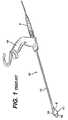
- a hollow shaft 12connected to a concave headpiece 16 located at the distal end of the shaft which provides a workspace 18 .
- An endoscope 5is typically inserted in the shaft so that the surgeon may view workspace.
- the leading edge of the headpiece 16is used for dissecting the vessel from the surrounding tissue.
- the devicemay also have guides located on the underside of the device which allow for the entry of other devices such as dissectors, ligation tools, and cutting tools, into the workspace.
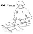
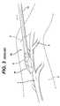
- FIGS. 2 and 3The traditional method for removal of a vessel section is shown in FIGS. 2 and 3 .
- an incision 3is made and the vessel 7 is located.
- the vesselis dissected from the surrounding tissue using the leading edge of the headpiece 16 of the device to separate the tissue from the vessel 7 .
- there is sufficient space created around the vessel 7so that other instruments can be inserted into the incision 3 via the guides located on the underside of the device.
- These instrumentsinclude ligation tools for securing side branch vessels 9 , vessel dissectors for performing a more complete dissection of the vessel 7 which is to be removed, and laproscopic scissors for the transection of both the side branch vessels 9 and the vessel 7 which is to be removed.
- the blunt dissectionis performed using the headpiece 16 of the device, and then any dissection to be performed under the device must be performed using other tools which must be inserted into the patient following the original incision 3 .
- any dissection to be performed under the devicemust be performed using other tools which must be inserted into the patient following the original incision 3 .
- a side branch vessel 9still further tools must be inserted into the incision 3 for performing the ligation and transection function.
- the present inventionovercomes the limitations of the devices of the prior art by providing a means by which a user can dissect both above and below the vessel which is to be removed using only a single tool. Further, the device is capable of ligating any side branch vessels without the insertion of any extra tools.
- the device of the present inventionminimizes the number of tool exchanges, the total number of tools required, and increases the users efficiency.
- a vessel harvesting devicecomprises a shaft having a lumen for insertion of an endoscope therethrough.
- the devicehas a handle located on a proximate end of the shaft for allowing an operator to manipulate the device.
- the deviceis also equipped with a headpiece connected to a distal end of the shaft, the headpiece has a top and a bottom portion, these two portions define a gap that surrounds a vessel inserted therein. The two portions of the headpiece are used to dissect above and below the vessel.
- the devicehas means for reciprocating either the top or the bottom portion relative to the other.
- the headpiecehas a first opening for receiving a dissected portion of the vessel and one or more second openings allowing a dissected portion of a vessel to exit the headpiece.
- the vesselis dissected from the surrounding tissue by reciprocating one of the top and bottom portions as the headpiece is advanced along the length of the vessel.
- the devicemay be fit with electro-surgical ligation electrodes for ligation of side branch vessels.
- the electrodescan be energized by an energizing means to ligate side branch vessels.
- the devicemay also be fit with a transection element.
- the transection elementmay be a raised portion of one of the upper and lower portions of the headpiece.
- the headpiecefor an endoscopic vessel harvesting device.
- the headpiececomprises a top portion for dissecting the tissue above a vessel which is to be removed.
- the top portionis typically rigidly attached to the endoscopic harvesting device.
- the devicefurther comprises a bottom portion for dissecting the tissue below the vessel to be removed.
- the bottom portionis connected to the endoscopic harvesting device by an articulated connection.
- the top and bottom portionsdefine a gap into which a vessel is inserted, the top and bottom portions then surround the vessel.
- There is an opening in the headpiecefor receiving a dissected portion of the vessel and one or more openings in the headpiece allowing a dissected portion of the vessel to exit the headpiece after dissection.
- the devicedissects a vessel from the surrounding tissue by reciprocating the bottom portion relative to the top portion while traversing the length of the vessel.
- the headpiecemay be fit with electro-surgical ligation electrodes for ligation of side branch vessels.
- the electrodescan be energized by an energizing means to ligate side branch vessels.
- the headpiecemay also be fit with a transection element.
- the transection elementmay be a raised portion of one of the upper and lower portions of the headpiece.
- a method of vessel dissectioncomprising a series of steps. Initially, the vessel to be harvested must be located, then an incision to expose the vessel must be made. Next, the surgeon must pre-dissect the vessel from tissue above the vessel. Then, the surgeon must pre-dissect below the vessel. Upon having a portion of the vessel dissected both above and below, a portion of the vessel which has been pre-dissected is inserted into a two piece headpiece of the vessel harvesting device so that a top and a bottom portion of the headpiece surround the vessel. Then the vessel is dissected from the tissue by projecting the top portion of the headpiece along the vessel and by simultaneously reciprocating the bottom portion of the headpiece.
- Dissectionis accomplished by repeating the previous two steps while traversing the length of the vessel. Finally the vessel is ligated, transected and removed. When a side branch vessel is uncovered it too must be ligated and transected using the ligation and transection means of the vessel harvesting device.
- FIG. 1illustrates a perspective view of an endoscopic vessel harvesting device of the prior art.
- FIG. 2illustrates a perspective view of a surgeon and an endoscopic vessel harvesting device of the prior art harvesting a vein located in a persons leg.
- FIG. 3illustrates an enlarged perspective view of the endoscopic vessel harvesting of FIG. 1 inserted into a patient during a procedure to harvest a vein.
- FIG. 4illustrates a perspective view of a preferred implementation of an endoscopic vessel harvesting device of the present invention.
- FIG. 5illustrates a perspective view of the endoscopic vessel harvesting device of FIG. 4 having the bottom portion of the headpiece retracted.
- FIG. 6illustrates an enlarged view of the two portion headpiece of the endoscopic harvesting device of FIG. 4 in which the bottom portion is extended.
- FIG. 7illustrates an enlarged view of the two portion headpiece of the endoscopic harvesting device of FIG. 4 in which the bottom portion is partially retracted.
- FIG. 8illustrates cross sectional view of a two portion headpiece for the endoscopic harvesting device of FIG. 7 , taken along line 8 - 8 .
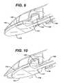
- FIG. 9illustrates a lower perspective view of the two portion headpiece f the endoscopic vessel harvesting device of FIG. 4 .
- FIG. 10illustrates a lower perspective view of the two portion headpiece of the endoscopic vessel harvesting device of FIG. 4 in which the lower portion is fully retracted.
- blunt dissection of the saphenous veinis performed on the anterior or upper side of the vessel upon insertion of a vessel harvesting device.
- a work spaceis created allowing further tools to be inserted into the patient so that the vessel can be further dissected, any side branch vessels can be ligated and transected and the vessel can be removed.
- the dissection of the vessels from tissues on the posterior or under side of the vesselsis performed using a variety of devices and can be a time consuming procedure requiring a great deal of skill to perform.
- the present inventiongreatly reduces the number of tools required to perform this very same task and provides an easier method for the removal of a vein from the patient.
- an endoscopic vessel harvesting devicefor the removal of blood vessels from a patient, generally referred to by the reference number 100 .
- this EVH device 100is often used for the removal of the saphenous vein from the leg of a person undergoing a CABG procedure.
- the embodiments discussed hereinare directed to the removal of such a vein however, the removal of the saphenous vein is only used by way of example only and not to limit the scope and spirit of the present invention.
- the EVH 100can be utilized for the removal of a number of vessels from a patient, including the radial artery of the lower arm, the lesser saphenous vein in the leg, and the interior epigastric artery in the abdomen.
- the EVH 100 deviceincludes, a headpiece 114 situated on the distal end 160 of a hollow shaft 116 .
- the hollow shaft 116is preferably a medical grade metal such as stainless steel.
- the headpiece 114is used for blunt vessel dissection, which is the separating of tissues connected to the vessel.
- the headpiece 114comprises a top portion 110 and a bottom portion 112 .
- the headpiece 114may be made of a medical grade transparent plastic such as a polycarbonate.
- the top and bottom portionscompletely surround a vessel which is inserted into the device.
- the top portion 110has an entry hole 132 (shown more clearly in FIG. 7 ) on the leading edge of the headpiece 114 .
- the entry hole 132provides a path for the vessel to enter the headpiece 114 .
- the headpiece 114also has holes 126 (also shown more clearly in FIG. 7 ) for the exiting of the vessel from the headpiece 114 after it has been dissected.
- the entry and exit holes 132 and 126are shown by way of example on the top and bottom portion 110 and 112 , respectively. However, the location of the entry and exit holes can be switched or both can be on one portion.
- bi-polar ligation electrodes 136 and 128are preferably affixed inside of the headpiece 114 for ligating side branch vessels.
- the location of the electrodes 136 , 128 in the headpiece 114allows the user of the device to ligate side branch vessels upon their discovery without the insertion of other tools. This increases the efficiency of the overall process.
- FIGS. 6-8show the relationship of the electrodes 128 and 136 to each other and other features of the headpiece 116 .
- Electrodes 128are attached to the shaft 116 of the device, these may be either manufactured as part of the shaft 116 , or they may be separately made and affixed, by welding for example.
- Electrodes 136are located on the bottom portion 112 of the headpiece 114 .
- the electrodes 136 and 128are not located in the same vertical plane but rather are off-set from one another, by an off-set distance of X the offset distance has been determined to be in the range of approximately 1-3 mm and preferably 2 mm. This position insures that the electrodes cannot touch as this would result in a shorted circuit.
- FIGS. 6 and 7show two pairs of electrodes, each off-set to a side of the headpiece 114 . By having two sets of electrodes 128 and 136 the device is capable of ligating side branch vessels on either side of the saphenous vein.
- the electrodes 136 , 128are preferably comprised of a positive and a negative terminal. One being located in the top portion and the second located in the bottom portion of the headpiece. They may be constantly energized or may be energized at will by the user.
- the triggering meansis located either in the handle 103 of the device, or in a foot pedal (not shown).
- the electrodesare connected to a conventional bi-polar RF generating device.
- FIG. 9shows the slide 138 having an electrically conductive portion 137 . This electrically conductive portion 137 connects to the lower electrodes 136 of the ligation means.
- the upper electrodes 128are connected to the shaft 116 .
- the shaft 116is connected to the RF energy generating means as is known in the art.
- the conductive portion 137 of the slide 138is insulated with an insulative coating to prevent inadvertent discharge of energy to surrounding tissue. Suitable insulative coatings are well known in the art, such as parylene-n.
- the vesselUpon entry of a side branch vessel between the two electrodes 128 , 136 the vessel is compressed by the proximity of the top and bottom portions 110 , 112 of the headpiece 114 . The vessel is then coagulated by the energized electrodes 128 , 136 . The coagulation results in effective ligation of the side branch vessel. Because the coagulation zone is limited to the small distance X, approximately 1-3 mm, the RF energy does not spread to the harvested vessel. These ligated sections may then be transected, freeing the saphenous vein from the side branch vessels. As shown in FIGS. 6-8 the transection means is preferably sharply raised cutting sections 134 located on the bottom portion 112 between the electrodes 128 and 136 .
- the cutting section 134transects the ligated vessel as the lower portion 112 is articulated back and forth over the side branch vessel.
- the cutting section 134also creates a high spot in the bottom portion 112 . This high spot assists in the compression of the side branch vessel for coagulation and ligation.
- the cutting section 134aligns with a cutting groove 135 in the top portion 110 to align the upper and lower portions of the headpiece 114 (as shown in FIG. 8 ), and to hold concentrate the compression at a tip of the cutting element 134 for dividing tissue when lower portion 112 is moved reciprocally relative to the upper portion 110 .
- the lower portion 112is springably held against the upper portion 110 so that various thickness of vessels may be captured in a compression zone between the cutting element and the cutting groove 135 .
- the transection means 134is fabricated from hard plastic the transection of vessels can be perform without the introduction of sharp metallic cutting instruments into the incision. This greatly reduces the chances of accidental injury in the surgical site.
- the compression zone Xis a sliding compression zone, and is used in combination with RF energizing of the electrodes 128 , 136 , ligation of the vessels can be done hemostatically. This is particularly assisted by a high compression zone formed at the tip of the cutting means 134 which allows the coagulation to occur simultaneously with the cutting of the vessel.
- the shaft 116may be inserted into a molded sheath of plastic 130 .
- This sheath of plastic 130extends the length of the shaft and may incorporate the upper portion 110 of the headpiece 114 . This allows for single component construction of a large section of the EVH 100 .
- the molded sheath 130also comprises an affixing means which connects the sheath 130 to the handle 102 .
- On the upper surface of the molded sheathis preferably a stop 106 which is used in connection with an actuation means 104 .
- On the underside of the molded sheathis a track 140 . Track 140 allows for the insertion of a slide 138 which can be connected to the actuator 104 of the articulation means.
- the track 140may be constructed so that when viewed in the cross section the opening is smaller than the width of the slide 138 . This configuration insures that the slide 138 cannot fall out of the track 140 .
- the bottom portion 112may be connected to the slide 138 and a handle of an articulating means 104 of the EVH 100 .
- the articulating meansallows the bottom portion 112 to move independently of the top portion 110 .
- the molded sheath 130could separate from the headpiece 114 .
- the top portion 110may be rigidly affixed to the shaft 116 of an EVH 100 .
- One method of articulation of the bottom portion 112is to attach an actuator 104 connected to a slide 138 the slide 138 in turn connects to the bottom portion 112 of the headpiece 114 .
- the slide 138runs in a track 140 located on the underside of the EVH 100 .
- the actuator 104provides the actuation means and the slide 138 allows for the translation of force from the actuator 104 to the bottom portion 112 of the headpiece 114 .
- the actuator 104is biased in the distal direction 160 by a spring 108 , which is forced against a stop 106 . By squeezing the actuator 104 the bottom portion 112 is moved towards the proximal end 150 of the EVH 100 .
- the slide 138Upon release of pressure on the actuator 104 the stored spring force moves the bottom portion 112 towards the distal end 160 of the EVH 100 .
- Another feature of the slide 138is that it may be constructed at least partially of an electrically conductive material. In the preferred implementation the slide 138 supplies RF energy to the electrode 136 .
- the actuation of the articulation meansmay be manually performed or it may be motorized. In the device shown in FIGS. 4 and 5 , the device is manually articulated.
- the articulation meansmay provide for variable stroke or longitudinal translation pf the lower portion 112 with respect to the upper portion 110 , preferably in the range of 0.1 mm to 5 mm, for either manual or motorized actuation means.
- the rate of articulationmay also be variable. Those skilled in the art can appreciate that a relatively high rate, such as 10 reciprocations/sec with a small stroke such as 0.2 mm may be provided via a motorized means, and variably controlled by the operator.
- FIG. 5there is shown a preventing means 118 for preventing the articulated portion of headpiece 114 from moving. This is preferably accomplished by preventing the articulating means from functioning.
- the handle 104is prevented from moving towards the distal end 160 of the device by the preventing means 118 , this in turn prevents the bottom portion 112 from moving in the same distal direction 160 .
- the Preventing means 118is a U-shaped clip which attaches to the molded sheath 130 in cooperation with a slot in the molded sheath 130 .
- the preventing meanscan be any means which prevents the spring 108 from acting on the handle 104 and moving the bottom portion 112 in the distal direction 160 .
- the bottom portion 112can be projected under the saphenous vein in a reciprocating fashion while the upper portion 110 is forced over the saphenous vein. This results in the effective dissection of both the upper and lower sides of the vessel without the use of extra tools. However, before this can occur the vessel must be inserted into the device.
- Insertion of the vesselis performed by extending the bottom portion 112 of the headpiece 114 in a manner as shown in FIG. 6 .
- a pre-dissected portion of the vesselcan be inserted into the headpiece 114 .
- the extended bottom portion 112is positioned under the vessel and the top portion 110 is drawn over the top of the vessel.
- a proximate portion of the vesselis allowed to sit in a notch 124 of the bottom portion 112 .
- the top portion 110is drawn over the lower portion that section of the vessel which was formerly located in notch 124 will then be positioned in the exit opening 126 .
- a distal portion of the vesselis positioned in the entry hole 132 . At this point the device is in position to begin operation.
- the headpiece 114is shown and discussed as an integral portion of the EVH 100 , alternatively it can be separately provided to fit onto existing vessel harvesting instruments.
- the dissection of the saphenous vein from the surrounding tissueis done in an efficient and expedient manner and requires a limited number of tools and with a minimum number of tool exchanges using the EVH 100 described above.
- the present methodstarts as is common for endoscopic vessel harvesting by locating the vessel which is to be removed. Next an incision is made to accommodate the insertion of the EVH 100 . Upon insertion of the leading edge of the EVH 100 blunt dissection of the tissue on the anterior or upper side of the vessel is performed.
- pre-dissection of a section of the vesselis performed.
- This pre-dissectionis performed so that a portion of the vessel can be fully exposed, of particular interest is the tissue located on the posterior or underside of the vessel.
- the pre-dissectioncan be performed using the EVH 100 , or with the use of specialized tools such as those known in the art.
- the vesselcan be inserted into the headpiece 114 of the EVH 100 . This insertion is performed as discussed above.
- the vessel's dissection from the surrounding tissueis continued by the movement of one of the top and bottom portions being thrust in the direction of the distal end 160 of the device. This movement is independent of the other of the top and bottom portions.
- One variation of dissectioncould be to alternate the movement of the top and bottom section so that dissection only occurs on one surface of the vessel at a time.
- a second variation of use of the EVH 100would be to repeatedly compress the handle 104 and release it. This causes the lower portion 112 of the headpiece 114 to continually dissect a short section of the underside of the saphenous vein. This repeated compression is performed while the upper portion 110 of the headpiece 114 is continually advanced along the upper side of the saphenous vein to dissect that surface. In either variation the actuation of the device is continued, dissecting above and below the vessel until sufficient length of the vessel is dissected.
- the saphenous veinwill invariably be connected to a series of side branch vessels. In order to remove the saphenous vein for further use these side branch vessels must be individually ligated and transected.
- the EVH deviceis equipped with bi-polar electrodes 128 , 136 located in the headpiece 114 . These electrodes are triggered by the user upon the placement of a side branch vessel between the two electrodes. These electrodes effectively ligate the side branch vessels and allow them to be transected. In the present invention, this is performed during the dissection of the vessel. For example, the lower portion 112 of the headpiece 114 dissects below the vessel and uncovers a side branch vessel.
- the side branch vesselUpon the movement of the upper portion to meet the lower portion, the side branch vessel will be forced between the electrodes 128 and 136 .
- One electrode 128being on the bottom portion 112 and the other electrode 136 being housed in the upper portion 110 of the headpiece 114 .
- the side branch vesselAs the upper portion 110 is slid over the bottom portion 112 the side branch vessel is compressed between the two electrodes 128 and 136 and the cutting means 134 .
- the userthen triggers the bi-polar electrodes either 128 or 136 and the side branch vessel is ligated.
- the side branch vesselis transected using the cutting means 134 by the reciprocating motion of the bottom portion 112 .
- the operatormay energize RF energy continuously while advancing the headpiece 114 of the device along the vessel, while maintaining visualization of the vessel and the side branches within the working space.
- the saphenous veinAfter sufficient length of the saphenous vein is dissected and the side branch vessels are ligated, the saphenous vein itself is ligated on both the distal and proximate ends. Once this is performed and the vessel is not attached to any of the other surrounding tissue it can be removed and used in further procedures, such as CABG.
Landscapes
- Health & Medical Sciences (AREA)
- Surgery (AREA)
- Life Sciences & Earth Sciences (AREA)
- Biomedical Technology (AREA)
- Nuclear Medicine, Radiotherapy & Molecular Imaging (AREA)
- Engineering & Computer Science (AREA)
- Rheumatology (AREA)
- Heart & Thoracic Surgery (AREA)
- Medical Informatics (AREA)
- Molecular Biology (AREA)
- Animal Behavior & Ethology (AREA)
- General Health & Medical Sciences (AREA)
- Public Health (AREA)
- Veterinary Medicine (AREA)
- Surgical Instruments (AREA)
Abstract
Description
Claims (18)
Priority Applications (1)
| Application Number | Priority Date | Filing Date | Title |
|---|---|---|---|
| US10/816,024US8052702B2 (en) | 2001-09-28 | 2004-04-01 | Vessel harvesting retractor with bilateral electrosurgical ligation |
Applications Claiming Priority (2)
| Application Number | Priority Date | Filing Date | Title |
|---|---|---|---|
| US09/967,205US6740102B2 (en) | 2001-09-28 | 2001-09-28 | Vessel harvesting retractor with bilateral electrosurgical ligation |
| US10/816,024US8052702B2 (en) | 2001-09-28 | 2004-04-01 | Vessel harvesting retractor with bilateral electrosurgical ligation |
Related Parent Applications (1)
| Application Number | Title | Priority Date | Filing Date |
|---|---|---|---|
| US09/967,205ContinuationUS6740102B2 (en) | 2001-09-28 | 2001-09-28 | Vessel harvesting retractor with bilateral electrosurgical ligation |
Publications (2)
| Publication Number | Publication Date |
|---|---|
| US20040186492A1 US20040186492A1 (en) | 2004-09-23 |
| US8052702B2true US8052702B2 (en) | 2011-11-08 |
Family
ID=25512456
Family Applications (2)
| Application Number | Title | Priority Date | Filing Date |
|---|---|---|---|
| US09/967,205Expired - Fee RelatedUS6740102B2 (en) | 2001-09-28 | 2001-09-28 | Vessel harvesting retractor with bilateral electrosurgical ligation |
| US10/816,024Expired - Fee RelatedUS8052702B2 (en) | 2001-09-28 | 2004-04-01 | Vessel harvesting retractor with bilateral electrosurgical ligation |
Family Applications Before (1)
| Application Number | Title | Priority Date | Filing Date |
|---|---|---|---|
| US09/967,205Expired - Fee RelatedUS6740102B2 (en) | 2001-09-28 | 2001-09-28 | Vessel harvesting retractor with bilateral electrosurgical ligation |
Country Status (1)
| Country | Link |
|---|---|
| US (2) | US6740102B2 (en) |
Cited By (17)
| Publication number | Priority date | Publication date | Assignee | Title |
|---|---|---|---|---|
| US20170245845A1 (en)* | 2016-02-29 | 2017-08-31 | Terumo Kabushiki Kaisha | Dissecting device |
| US20170245922A1 (en)* | 2016-02-29 | 2017-08-31 | Terumo Kabushiki Kaisha | Dissecting device and dissecting system |
| US10687793B2 (en) | 2017-07-18 | 2020-06-23 | Obp Medical Corporation | Minimally invasive no touch (MINT) procedure for harvesting the great saphenous vein (GSV) and venous hydrodissector and retractor for use during the MINT procedure |
| US10722621B2 (en) | 2016-07-11 | 2020-07-28 | Obp Medical Corporation | Illuminated suction device |
| US10799229B2 (en) | 2018-02-20 | 2020-10-13 | Obp Medical Corporation | Illuminated medical devices |
| USD904607S1 (en) | 2019-05-07 | 2020-12-08 | Obp Medical Corporation | Nasal retractor |
| US10881387B2 (en) | 2015-06-03 | 2021-01-05 | Obp Medical Corporation | Retractor |
| US10912455B2 (en) | 2017-10-19 | 2021-02-09 | Obp Medical Corporation | Medical devices with battery removal |
| USD911521S1 (en) | 2019-02-19 | 2021-02-23 | Obp Medical Corporation | Handle for medical devices including surgical retractors |
| US10939899B2 (en) | 2015-06-03 | 2021-03-09 | Obp Medical Corporation | End cap assembly for retractor and other medical devices |
| US10952712B2 (en) | 2015-06-03 | 2021-03-23 | Obp Medical Corporation | Retractor |
| US10959609B1 (en) | 2020-01-31 | 2021-03-30 | Obp Medical Corporation | Illuminated suction device |
| US10966702B1 (en) | 2020-02-25 | 2021-04-06 | Obp Medical Corporation | Illuminated dual-blade retractor |
| US11197662B2 (en) | 2015-02-05 | 2021-12-14 | Obp Surgical Corporation | Illuminated surgical retractor |
| US11744454B2 (en) | 2010-09-28 | 2023-09-05 | Obp Medical Corporation | Speculum |
| US12089829B2 (en) | 2015-02-05 | 2024-09-17 | Obp Surgical Corporation | Illuminated surgical retractor |
| US12318080B2 (en) | 2023-07-21 | 2025-06-03 | Coopersurgical, Inc. | Illuminated surgical retractor capable of hand-held operation and of being mounted to a fixed frame |
Families Citing this family (62)
| Publication number | Priority date | Publication date | Assignee | Title |
|---|---|---|---|---|
| US5601581A (en)* | 1995-05-19 | 1997-02-11 | General Surgical Innovations, Inc. | Methods and devices for blood vessel harvesting |
| EP0979635A2 (en) | 1998-08-12 | 2000-02-16 | Origin Medsystems, Inc. | Tissue dissector apparatus |
| US6953461B2 (en) | 2002-05-16 | 2005-10-11 | Tissuelink Medical, Inc. | Fluid-assisted medical devices, systems and methods |
| US6689131B2 (en) | 2001-03-08 | 2004-02-10 | Tissuelink Medical, Inc. | Electrosurgical device having a tissue reduction sensor |
| US6558385B1 (en) | 2000-09-22 | 2003-05-06 | Tissuelink Medical, Inc. | Fluid-assisted medical device |
| US8048070B2 (en) | 2000-03-06 | 2011-11-01 | Salient Surgical Technologies, Inc. | Fluid-assisted medical devices, systems and methods |
| ES2306706T3 (en) | 2000-03-06 | 2008-11-16 | Salient Surgical Technologies, Inc. | FLUID SUPPLY SYSTEM AND CONTROLLER FOR ELECTROCHURGICAL DEVICES. |
| US7811282B2 (en) | 2000-03-06 | 2010-10-12 | Salient Surgical Technologies, Inc. | Fluid-assisted electrosurgical devices, electrosurgical unit with pump and methods of use thereof |
| US6558313B1 (en)* | 2000-11-17 | 2003-05-06 | Embro Corporation | Vein harvesting system and method |
| AU2002357166A1 (en) | 2001-12-12 | 2003-06-23 | Tissuelink Medical, Inc. | Fluid-assisted medical devices, systems and methods |
| WO2004039416A2 (en) | 2002-10-29 | 2004-05-13 | Tissuelink Medical, Inc. | Fluid-assisted electrosurgical scissors and methods |
| US20040236231A1 (en)* | 2003-05-23 | 2004-11-25 | Embro Corporation | Light catheter for illuminating tissue structures |
| US7138316B2 (en)* | 2003-09-23 | 2006-11-21 | Intel Corporation | Semiconductor channel on insulator structure |
| US20060173474A1 (en)* | 2003-10-31 | 2006-08-03 | Parris Wellman | Surgical device having a track to guide an actuator |
| US20050096645A1 (en)* | 2003-10-31 | 2005-05-05 | Parris Wellman | Multitool surgical device |
| US7662164B2 (en)* | 2003-10-31 | 2010-02-16 | Olympus Corporation | Living-body tissue removing apparatus |
| US20050149094A1 (en)* | 2003-10-31 | 2005-07-07 | Olympus Corporation | Trocar |
| US20050096646A1 (en)* | 2003-10-31 | 2005-05-05 | Parris Wellman | Surgical system for retracting and severing tissue |
| US7331971B2 (en)* | 2003-10-31 | 2008-02-19 | Olympus Corporation | Living-body tissue removing apparatus |
| US20050096670A1 (en)* | 2003-10-31 | 2005-05-05 | Parris Wellman | Surgical end effector |
| US8105231B2 (en)* | 2003-10-31 | 2012-01-31 | Olympus Corporation | Living-body tissue removing apparatus |
| US7314479B2 (en)* | 2003-10-31 | 2008-01-01 | Parris Wellman | Space-creating retractor with vessel manipulator |
| US20050096671A1 (en)* | 2003-10-31 | 2005-05-05 | Parris Wellman | Control mechanism for a surgical instrument |
| US8038611B2 (en)* | 2003-12-18 | 2011-10-18 | Depuy Spine, Inc. | Surgical methods and surgical kits |
| US7727232B1 (en) | 2004-02-04 | 2010-06-01 | Salient Surgical Technologies, Inc. | Fluid-assisted medical devices and methods |
| US7762951B2 (en)* | 2004-06-25 | 2010-07-27 | Medtronic, Inc. | Vein harvesting system including dilator shaft and removable retractor housing |
| CN101111200B (en)* | 2004-12-17 | 2010-05-12 | 国立大学法人京都大学 | Cap attachment and endoscope with cutting function |
| US7951077B2 (en)* | 2005-07-15 | 2011-05-31 | Sayeg Ayoub Dr | Method and instruments for breast augmentation mammaplasty |
| JP4783790B2 (en)* | 2005-08-18 | 2011-09-28 | オリンパスメディカルシステムズ株式会社 | Bipolar cutter |
| US7367983B2 (en) | 2005-09-15 | 2008-05-06 | Dziadik Stephen P | Vessel harvesting apparatus |
| US7981031B2 (en)* | 2006-01-04 | 2011-07-19 | Depuy Spine, Inc. | Surgical access devices and methods of minimally invasive surgery |
| US7918792B2 (en) | 2006-01-04 | 2011-04-05 | Depuy Spine, Inc. | Surgical retractor for use with minimally invasive spinal stabilization systems and methods of minimally invasive surgery |
| US7758501B2 (en) | 2006-01-04 | 2010-07-20 | Depuy Spine, Inc. | Surgical reactors and methods of minimally invasive surgery |
| US7955257B2 (en) | 2006-01-05 | 2011-06-07 | Depuy Spine, Inc. | Non-rigid surgical retractor |
| USD622380S1 (en)* | 2006-03-10 | 2010-08-24 | Medical Device Innovations Limited | Surgical instrument |
| USD623739S1 (en)* | 2006-03-10 | 2010-09-14 | Medical Device Innovations Limited | Surgical instrument handle |
| US7547314B2 (en)* | 2006-05-26 | 2009-06-16 | Terumo Cardiovascular Systems Corporation | Self-cleaning endoscopic vein harvester rod |
| US9770230B2 (en)* | 2006-06-01 | 2017-09-26 | Maquet Cardiovascular Llc | Endoscopic vessel harvesting system components |
| KR100828135B1 (en)* | 2006-12-13 | 2008-05-08 | 이은규 | Biotissue exfoliator for endoscope |
| ES2442241T3 (en) | 2008-03-31 | 2014-02-10 | Applied Medical Resources Corporation | Electrosurgical system with a switching mechanism |
| US20120289947A1 (en)* | 2010-01-18 | 2012-11-15 | Wolfgang Neuberger | Device and method for removing veins |
| US9144455B2 (en) | 2010-06-07 | 2015-09-29 | Just Right Surgical, Llc | Low power tissue sealing device and method |
| AU2011308509B8 (en) | 2010-10-01 | 2015-04-02 | Applied Medical Resources Corporation | Electrosurgical instrument |
| US9039694B2 (en) | 2010-10-22 | 2015-05-26 | Just Right Surgical, Llc | RF generator system for surgical vessel sealing |
| EP2635196A4 (en)* | 2010-11-04 | 2015-10-14 | Univ Virginia Patent Found | DEVICE AND METHOD FOR SAFELY EXTENDING SURGICAL INCISIONS WITH MINIMAL INVASION |
| USD660422S1 (en)* | 2010-12-23 | 2012-05-22 | Karl Storz Gmbh & Co. Kg | Spate for thyroid surgery |
| WO2015176074A2 (en) | 2014-05-16 | 2015-11-19 | Applied Medical Resources Corporation | Electrosurgical system |
| JP6735272B2 (en) | 2014-05-30 | 2020-08-05 | アプライド メディカル リソーシーズ コーポレイション | Electrosurgical sealing and incision system |
| JP6596019B2 (en)* | 2014-12-04 | 2019-10-23 | テルモ株式会社 | Blood vessel peeling device |
| KR102545505B1 (en) | 2014-12-23 | 2023-06-20 | 어플라이드 메디컬 리소시스 코포레이션 | Bipolar Electrosurgical Sealers and Dividers |
| USD748259S1 (en) | 2014-12-29 | 2016-01-26 | Applied Medical Resources Corporation | Electrosurgical instrument |
| WO2016117151A1 (en) | 2015-01-19 | 2016-07-28 | テルモ株式会社 | Blood vessel removal device |
| US10219791B2 (en)* | 2015-12-31 | 2019-03-05 | Terumo Kabushiki Kaisha | Medical device and method |
| US20170189051A1 (en)* | 2015-12-31 | 2017-07-06 | Terumo Kabushiki Kaisha | Medical device and method |
| WO2017161177A1 (en)* | 2016-03-17 | 2017-09-21 | Trice Medical, Inc. | Clot evacuation and visualization devices and methods of use |
| DE102017113729A1 (en)* | 2017-06-21 | 2018-12-27 | Josef Heinen | Medical instrument |
| JP7610777B2 (en) | 2018-09-05 | 2025-01-09 | アプライド メディカル リソーシーズ コーポレイション | Electrosurgical Generator Control System |
| USD904611S1 (en) | 2018-10-10 | 2020-12-08 | Bolder Surgical, Llc | Jaw design for a surgical instrument |
| US11696796B2 (en) | 2018-11-16 | 2023-07-11 | Applied Medical Resources Corporation | Electrosurgical system |
| US10492670B1 (en)* | 2018-12-18 | 2019-12-03 | 3Nt Medical Ltd. | Ear visualization and treatment system |
| USD934423S1 (en) | 2020-09-11 | 2021-10-26 | Bolder Surgical, Llc | End effector for a surgical device |
| USD1046129S1 (en) | 2021-04-14 | 2024-10-08 | Bolder Surgical, Llc | End effector for a surgical instrument |
Citations (19)
| Publication number | Priority date | Publication date | Assignee | Title |
|---|---|---|---|---|
| US5667480A (en) | 1995-10-20 | 1997-09-16 | Ethicon Endo-Surgery, Inc. | Method and devices for endoscopic vessel harvesting |
| US5695514A (en) | 1995-07-13 | 1997-12-09 | Guidant Corporation | Method and apparatus for harvesting blood vessels |
| US5759150A (en)* | 1995-07-07 | 1998-06-02 | Olympus Optical Co., Ltd. | System for evulsing subcutaneous tissue |
| US5817013A (en) | 1996-03-19 | 1998-10-06 | Enable Medical Corporation | Method and apparatus for the minimally invasive harvesting of a saphenous vein and the like |
| US5891140A (en) | 1996-12-23 | 1999-04-06 | Cardiothoracic Systems, Inc. | Electrosurgical device for harvesting a vessel especially the internal mammary artery for coronary artery bypass grafting |
| US5913818A (en) | 1997-06-02 | 1999-06-22 | General Surgical Innovations, Inc. | Vascular retractor |
| US5916233A (en) | 1998-03-05 | 1999-06-29 | Origin Medsystems, Inc. | Vessel harvesting method and instrument including access port |
| US5921919A (en) | 1997-05-30 | 1999-07-13 | Origin Medsystems, Inc. | Perivascular self-retaining retractor and method |
| US5970982A (en) | 1997-02-20 | 1999-10-26 | Perkins; Rodney C. | Minimally invasive biological vessel harvesting method |
| US6019771A (en)* | 1996-12-02 | 2000-02-01 | Cardiothoracic Systems, Inc. | Devices and methods for minimally invasive harvesting of a vessel especially the saphenous vein for coronary bypass grafting |
| US6036713A (en) | 1996-01-24 | 2000-03-14 | Archimedes Surgical, Inc. | Instruments and methods for minimally invasive vascular procedures |
| US6042538A (en) | 1998-11-18 | 2000-03-28 | Emory University | Device for endoscopic vessel harvesting |
| US6083223A (en) | 1997-08-28 | 2000-07-04 | Baker; James A. | Methods and apparatus for welding blood vessels |
| US6129661A (en) | 1998-04-09 | 2000-10-10 | Smith & Nephew, Inc. | Endoscopic instrumentation with working channel |
| US6193653B1 (en)* | 1998-02-06 | 2001-02-27 | Ethicon Endo-Surgery, Inc. | Methods and devices for visualizing, dissecting and harvesting vessels and the like |
| US6277137B1 (en) | 1995-04-12 | 2001-08-21 | Origin Medsystems | Tissue separation cannula with dissection probe and method |
| US6296640B1 (en) | 1998-02-06 | 2001-10-02 | Ethicon Endo-Surgery, Inc. | RF bipolar end effector for use in electrosurgical instruments |
| US6319265B1 (en) | 1998-02-27 | 2001-11-20 | Cardiothoracic Systems, Inc. | Dissecting retractor for harvesting vessels |
| US6520975B2 (en) | 1999-02-04 | 2003-02-18 | Antonio Carlos Branco | Kit for endovascular venous surgery |
- 2001
- 2001-09-28USUS09/967,205patent/US6740102B2/ennot_activeExpired - Fee Related
- 2004
- 2004-04-01USUS10/816,024patent/US8052702B2/ennot_activeExpired - Fee Related
Patent Citations (24)
| Publication number | Priority date | Publication date | Assignee | Title |
|---|---|---|---|---|
| US6277137B1 (en) | 1995-04-12 | 2001-08-21 | Origin Medsystems | Tissue separation cannula with dissection probe and method |
| US5759150A (en)* | 1995-07-07 | 1998-06-02 | Olympus Optical Co., Ltd. | System for evulsing subcutaneous tissue |
| US5695514A (en) | 1995-07-13 | 1997-12-09 | Guidant Corporation | Method and apparatus for harvesting blood vessels |
| US5722934A (en) | 1995-10-20 | 1998-03-03 | Ethicon Endo-Surgery, Inc. | Method and devices for endoscopoic vessel harvesting |
| US5725479A (en) | 1995-10-20 | 1998-03-10 | Ethicon Endo-Surgery, Inc. | Method and devices for endoscopic vessel harvesting |
| US5667480A (en) | 1995-10-20 | 1997-09-16 | Ethicon Endo-Surgery, Inc. | Method and devices for endoscopic vessel harvesting |
| US6036713A (en) | 1996-01-24 | 2000-03-14 | Archimedes Surgical, Inc. | Instruments and methods for minimally invasive vascular procedures |
| US5817013A (en) | 1996-03-19 | 1998-10-06 | Enable Medical Corporation | Method and apparatus for the minimally invasive harvesting of a saphenous vein and the like |
| US6022313A (en) | 1996-03-19 | 2000-02-08 | Cardiothoracic Systems, Inc. | Method and apparatus for the minimally invasive harvesting of a saphenous vein and the like |
| US6019771A (en)* | 1996-12-02 | 2000-02-01 | Cardiothoracic Systems, Inc. | Devices and methods for minimally invasive harvesting of a vessel especially the saphenous vein for coronary bypass grafting |
| US5891140A (en) | 1996-12-23 | 1999-04-06 | Cardiothoracic Systems, Inc. | Electrosurgical device for harvesting a vessel especially the internal mammary artery for coronary artery bypass grafting |
| US5970982A (en) | 1997-02-20 | 1999-10-26 | Perkins; Rodney C. | Minimally invasive biological vessel harvesting method |
| US5921919A (en) | 1997-05-30 | 1999-07-13 | Origin Medsystems, Inc. | Perivascular self-retaining retractor and method |
| US6053863A (en) | 1997-05-30 | 2000-04-25 | Chin; Albert K. | Perivascular self-retaining retractor and method |
| US6228024B1 (en) | 1997-06-02 | 2001-05-08 | General Surgical Innovations, Inc. | Vascular retractor |
| US5913818A (en) | 1997-06-02 | 1999-06-22 | General Surgical Innovations, Inc. | Vascular retractor |
| US6083223A (en) | 1997-08-28 | 2000-07-04 | Baker; James A. | Methods and apparatus for welding blood vessels |
| US6296640B1 (en) | 1998-02-06 | 2001-10-02 | Ethicon Endo-Surgery, Inc. | RF bipolar end effector for use in electrosurgical instruments |
| US6193653B1 (en)* | 1998-02-06 | 2001-02-27 | Ethicon Endo-Surgery, Inc. | Methods and devices for visualizing, dissecting and harvesting vessels and the like |
| US6319265B1 (en) | 1998-02-27 | 2001-11-20 | Cardiothoracic Systems, Inc. | Dissecting retractor for harvesting vessels |
| US5916233A (en) | 1998-03-05 | 1999-06-29 | Origin Medsystems, Inc. | Vessel harvesting method and instrument including access port |
| US6129661A (en) | 1998-04-09 | 2000-10-10 | Smith & Nephew, Inc. | Endoscopic instrumentation with working channel |
| US6042538A (en) | 1998-11-18 | 2000-03-28 | Emory University | Device for endoscopic vessel harvesting |
| US6520975B2 (en) | 1999-02-04 | 2003-02-18 | Antonio Carlos Branco | Kit for endovascular venous surgery |
Cited By (32)
| Publication number | Priority date | Publication date | Assignee | Title |
|---|---|---|---|---|
| US11744454B2 (en) | 2010-09-28 | 2023-09-05 | Obp Medical Corporation | Speculum |
| US12419510B2 (en) | 2010-09-28 | 2025-09-23 | Coopersurgical, Inc. | Speculum |
| US11197662B2 (en) | 2015-02-05 | 2021-12-14 | Obp Surgical Corporation | Illuminated surgical retractor |
| US12089829B2 (en) | 2015-02-05 | 2024-09-17 | Obp Surgical Corporation | Illuminated surgical retractor |
| US12329370B2 (en) | 2015-02-05 | 2025-06-17 | Coopersurgical, Inc. | Illuminated surgical retractor |
| US12201287B2 (en) | 2015-06-03 | 2025-01-21 | Coopersurgical, Inc. | Retractor |
| US10881387B2 (en) | 2015-06-03 | 2021-01-05 | Obp Medical Corporation | Retractor |
| US10939899B2 (en) | 2015-06-03 | 2021-03-09 | Obp Medical Corporation | End cap assembly for retractor and other medical devices |
| US10952712B2 (en) | 2015-06-03 | 2021-03-23 | Obp Medical Corporation | Retractor |
| US11622756B2 (en) | 2015-06-03 | 2023-04-11 | Obp Surgical Corporation | End cap assembly for retractor and other medical devices |
| US10966699B2 (en) | 2015-06-03 | 2021-04-06 | Obp Medical Corporation | Retractor |
| US20170245922A1 (en)* | 2016-02-29 | 2017-08-31 | Terumo Kabushiki Kaisha | Dissecting device and dissecting system |
| US20170245845A1 (en)* | 2016-02-29 | 2017-08-31 | Terumo Kabushiki Kaisha | Dissecting device |
| US10485523B2 (en)* | 2016-02-29 | 2019-11-26 | Terumo Kabushiki Kaisha | Dissecting device |
| US10499978B2 (en)* | 2016-02-29 | 2019-12-10 | Terumo Kabushiki Kaisha | Dissecting device and dissecting system |
| US10722621B2 (en) | 2016-07-11 | 2020-07-28 | Obp Medical Corporation | Illuminated suction device |
| US11717374B2 (en) | 2016-07-11 | 2023-08-08 | Obp Surgical Corporation | Illuminated suction device |
| US11540817B2 (en) | 2017-07-18 | 2023-01-03 | Obp Surgical Corporation | Minimally invasive no touch (MINT) procedure for harvesting the great saphenous vein (GSV) and venous hydrodissector and retractor for use during the mint procedure |
| US10687793B2 (en) | 2017-07-18 | 2020-06-23 | Obp Medical Corporation | Minimally invasive no touch (MINT) procedure for harvesting the great saphenous vein (GSV) and venous hydrodissector and retractor for use during the MINT procedure |
| US12383129B2 (en) | 2017-10-19 | 2025-08-12 | Coopersurgical, Inc. | Medical devices with battery removal |
| US11253145B2 (en) | 2017-10-19 | 2022-02-22 | Obp Medical Corporation | Speculum |
| US10912455B2 (en) | 2017-10-19 | 2021-02-09 | Obp Medical Corporation | Medical devices with battery removal |
| US10799229B2 (en) | 2018-02-20 | 2020-10-13 | Obp Medical Corporation | Illuminated medical devices |
| US11744568B2 (en) | 2018-02-20 | 2023-09-05 | Obp Surgical Corporation | Illuminated medical devices |
| USD911521S1 (en) | 2019-02-19 | 2021-02-23 | Obp Medical Corporation | Handle for medical devices including surgical retractors |
| USD904607S1 (en) | 2019-05-07 | 2020-12-08 | Obp Medical Corporation | Nasal retractor |
| US10959609B1 (en) | 2020-01-31 | 2021-03-30 | Obp Medical Corporation | Illuminated suction device |
| US12246124B2 (en) | 2020-01-31 | 2025-03-11 | Coopersurgical, Inc. | Illuminated suction device |
| US11617822B2 (en) | 2020-01-31 | 2023-04-04 | Obp Surgical Corporation | Illuminated suction device |
| US10966702B1 (en) | 2020-02-25 | 2021-04-06 | Obp Medical Corporation | Illuminated dual-blade retractor |
| US11622758B2 (en) | 2020-02-25 | 2023-04-11 | Obp Surgical Corporation | Illuminated dual-blade retractor |
| US12318080B2 (en) | 2023-07-21 | 2025-06-03 | Coopersurgical, Inc. | Illuminated surgical retractor capable of hand-held operation and of being mounted to a fixed frame |
Also Published As
| Publication number | Publication date |
|---|---|
| US20040186492A1 (en) | 2004-09-23 |
| US20030065349A1 (en) | 2003-04-03 |
| US6740102B2 (en) | 2004-05-25 |
Similar Documents
| Publication | Publication Date | Title |
|---|---|---|
| US8052702B2 (en) | Vessel harvesting retractor with bilateral electrosurgical ligation | |
| US6656176B2 (en) | Vessel harvesting retractor with integral electrosurgical clamping elements | |
| US6592582B2 (en) | Vessel harvesting retractor with electrosurgical plunger | |
| US6616661B2 (en) | Surgical device for clamping, ligating, and severing tissue | |
| US6527771B1 (en) | Surgical device for endoscopic vein harvesting | |
| US5913866A (en) | Devices and methods for harvesting vascular conduits | |
| US6019771A (en) | Devices and methods for minimally invasive harvesting of a vessel especially the saphenous vein for coronary bypass grafting | |
| US6080175A (en) | Surgical cutting instrument and method of use | |
| EP1323392B1 (en) | Treatment device for cutting living tissue | |
| US6387094B1 (en) | Medical instrument for dissecting tissue | |
| US6453906B1 (en) | Method for facilitating the detachment of an artery and the like | |
| US6660016B2 (en) | Integrated vein dissector and cauterizing apparatus for endoscopic harvesting of blood vessels | |
| EP0589453A2 (en) | Bipolar surgical forceps | |
| US20060211916A1 (en) | Living tissue harvesting apparatus | |
| US20020099375A1 (en) | Electrosurgical instrument with minimally invasive jaws | |
| US8298229B2 (en) | Body tissue incision apparatus | |
| KR19980064465A (en) | Electrosurgical apparatus for harvesting of internal mammary arteries for blood vessels, especially coronary artery bypass grafts | |
| WO1999017661A1 (en) | Subcutaneous endoscopic dissector | |
| US6379298B2 (en) | Medical dissection spatula having spreadable spatula jaw parts | |
| US20060173474A1 (en) | Surgical device having a track to guide an actuator |
Legal Events
| Date | Code | Title | Description |
|---|---|---|---|
| AS | Assignment | Owner name:DATASCOPE CORP., NEW JERSEY Free format text:ASSIGNMENT OF ASSIGNORS INTEREST;ASSIGNOR:ETHICON, INC.;REEL/FRAME:016987/0712 Effective date:20060103 Owner name:DATASCOPE CORP., NEW JERSEY Free format text:ASSIGNMENT OF ASSIGNORS INTEREST;ASSIGNOR:ETHICON, INC.;REEL/FRAME:016987/0727 Effective date:20060103 | |
| AS | Assignment | Owner name:DATASCOPE CORP., NEW JERSEY Free format text:ASSIGNMENT OF ASSIGNORS INTEREST;ASSIGNOR:ETHICON, INC.;REEL/FRAME:022043/0201 Effective date:20060103 | |
| AS | Assignment | Owner name:SORIN GROUP USA, INC., COLORADO Free format text:ASSIGNMENT OF ASSIGNORS INTEREST;ASSIGNOR:DATASCOPE CORP.;REEL/FRAME:023234/0482 Effective date:20090825 | |
| AS | Assignment | Owner name:ETHICON, INC.,NEW JERSEY Free format text:ASSIGNMENT OF ASSIGNORS INTEREST;ASSIGNORS:HESS, CHRISTOPHER J.;CLEM, MICHAEL F.;KNIGHT, GARY W.;AND OTHERS;SIGNING DATES FROM 20011206 TO 20011207;REEL/FRAME:024340/0736 Owner name:ETHICON, INC., NEW JERSEY Free format text:ASSIGNMENT OF ASSIGNORS INTEREST;ASSIGNORS:HESS, CHRISTOPHER J.;CLEM, MICHAEL F.;KNIGHT, GARY W.;AND OTHERS;SIGNING DATES FROM 20011206 TO 20011207;REEL/FRAME:024340/0736 | |
| STCF | Information on status: patent grant | Free format text:PATENTED CASE | |
| FPAY | Fee payment | Year of fee payment:4 | |
| FEPP | Fee payment procedure | Free format text:MAINTENANCE FEE REMINDER MAILED (ORIGINAL EVENT CODE: REM.); ENTITY STATUS OF PATENT OWNER: LARGE ENTITY | |
| LAPS | Lapse for failure to pay maintenance fees | Free format text:PATENT EXPIRED FOR FAILURE TO PAY MAINTENANCE FEES (ORIGINAL EVENT CODE: EXP.); ENTITY STATUS OF PATENT OWNER: LARGE ENTITY | |
| STCH | Information on status: patent discontinuation | Free format text:PATENT EXPIRED DUE TO NONPAYMENT OF MAINTENANCE FEES UNDER 37 CFR 1.362 | |
| FP | Lapsed due to failure to pay maintenance fee | Effective date:20191108 |