US8052691B2 - Spring loaded fixation element insertion device - Google Patents
Spring loaded fixation element insertion deviceDownload PDFInfo
- Publication number
- US8052691B2 US8052691B2US10/992,259US99225904AUS8052691B2US 8052691 B2US8052691 B2US 8052691B2US 99225904 AUS99225904 AUS 99225904AUS 8052691 B2US8052691 B2US 8052691B2
- Authority
- US
- United States
- Prior art keywords
- distal
- handle
- holding sleeve
- spring
- shaft
- Prior art date
- Legal status (The legal status is an assumption and is not a legal conclusion. Google has not performed a legal analysis and makes no representation as to the accuracy of the status listed.)
- Expired - Fee Related, expires
Links
Images


Classifications
- A—HUMAN NECESSITIES
- A61—MEDICAL OR VETERINARY SCIENCE; HYGIENE
- A61B—DIAGNOSIS; SURGERY; IDENTIFICATION
- A61B17/00—Surgical instruments, devices or methods
- A61B17/068—Surgical staplers, e.g. containing multiple staples or clamps
- A—HUMAN NECESSITIES
- A61—MEDICAL OR VETERINARY SCIENCE; HYGIENE
- A61B—DIAGNOSIS; SURGERY; IDENTIFICATION
- A61B17/00—Surgical instruments, devices or methods
- A61B17/56—Surgical instruments or methods for treatment of bones or joints; Devices specially adapted therefor
- A61B17/58—Surgical instruments or methods for treatment of bones or joints; Devices specially adapted therefor for osteosynthesis, e.g. bone plates, screws or setting implements
- A61B17/88—Osteosynthesis instruments; Methods or means for implanting or extracting internal or external fixation devices
- A61B17/8875—Screwdrivers, spanners or wrenches
- A—HUMAN NECESSITIES
- A61—MEDICAL OR VETERINARY SCIENCE; HYGIENE
- A61B—DIAGNOSIS; SURGERY; IDENTIFICATION
- A61B17/00—Surgical instruments, devices or methods
- A61B17/56—Surgical instruments or methods for treatment of bones or joints; Devices specially adapted therefor
- A61B17/58—Surgical instruments or methods for treatment of bones or joints; Devices specially adapted therefor for osteosynthesis, e.g. bone plates, screws or setting implements
- A61B17/88—Osteosynthesis instruments; Methods or means for implanting or extracting internal or external fixation devices
- A61B17/92—Impactors or extractors, e.g. for removing intramedullary devices
- B—PERFORMING OPERATIONS; TRANSPORTING
- B25—HAND TOOLS; PORTABLE POWER-DRIVEN TOOLS; MANIPULATORS
- B25B—TOOLS OR BENCH DEVICES NOT OTHERWISE PROVIDED FOR, FOR FASTENING, CONNECTING, DISENGAGING OR HOLDING
- B25B15/00—Screwdrivers
- B25B15/02—Screwdrivers operated by rotating the handle
- B—PERFORMING OPERATIONS; TRANSPORTING
- B25—HAND TOOLS; PORTABLE POWER-DRIVEN TOOLS; MANIPULATORS
- B25B—TOOLS OR BENCH DEVICES NOT OTHERWISE PROVIDED FOR, FOR FASTENING, CONNECTING, DISENGAGING OR HOLDING
- B25B23/00—Details of, or accessories for, spanners, wrenches, screwdrivers
- B25B23/02—Arrangements for handling screws or nuts
- B25B23/04—Arrangements for handling screws or nuts for feeding screws or nuts
- B25B23/06—Arrangements for handling screws or nuts for feeding screws or nuts using built-in magazine
- B25B23/065—Arrangements for handling screws or nuts for feeding screws or nuts using built-in magazine the magazine being coaxial with the tool axis
- B—PERFORMING OPERATIONS; TRANSPORTING
- B25—HAND TOOLS; PORTABLE POWER-DRIVEN TOOLS; MANIPULATORS
- B25B—TOOLS OR BENCH DEVICES NOT OTHERWISE PROVIDED FOR, FOR FASTENING, CONNECTING, DISENGAGING OR HOLDING
- B25B23/00—Details of, or accessories for, spanners, wrenches, screwdrivers
- B25B23/02—Arrangements for handling screws or nuts
- B25B23/08—Arrangements for handling screws or nuts for holding or positioning screw or nut prior to or during its rotation
- B25B23/10—Arrangements for handling screws or nuts for holding or positioning screw or nut prior to or during its rotation using mechanical gripping means
- B25B23/101—Arrangements for handling screws or nuts for holding or positioning screw or nut prior to or during its rotation using mechanical gripping means for hand-driven screw-drivers
- A—HUMAN NECESSITIES
- A61—MEDICAL OR VETERINARY SCIENCE; HYGIENE
- A61B—DIAGNOSIS; SURGERY; IDENTIFICATION
- A61B17/00—Surgical instruments, devices or methods
- A61B17/064—Surgical staples, i.e. penetrating the tissue
- A61B17/0642—Surgical staples, i.e. penetrating the tissue for bones, e.g. for osteosynthesis or connecting tendon to bone
- A—HUMAN NECESSITIES
- A61—MEDICAL OR VETERINARY SCIENCE; HYGIENE
- A61B—DIAGNOSIS; SURGERY; IDENTIFICATION
- A61B17/00—Surgical instruments, devices or methods
- A61B17/064—Surgical staples, i.e. penetrating the tissue
- A61B2017/0647—Surgical staples, i.e. penetrating the tissue having one single leg, e.g. tacks
- A—HUMAN NECESSITIES
- A61—MEDICAL OR VETERINARY SCIENCE; HYGIENE
- A61B—DIAGNOSIS; SURGERY; IDENTIFICATION
- A61B17/00—Surgical instruments, devices or methods
- A61B17/56—Surgical instruments or methods for treatment of bones or joints; Devices specially adapted therefor
- A61B17/58—Surgical instruments or methods for treatment of bones or joints; Devices specially adapted therefor for osteosynthesis, e.g. bone plates, screws or setting implements
- A61B17/88—Osteosynthesis instruments; Methods or means for implanting or extracting internal or external fixation devices
- A61B17/92—Impactors or extractors, e.g. for removing intramedullary devices
- A61B2017/922—Devices for impaction, impact element
- A61B2017/924—Impact element driving means
- A61B2017/925—Impact element driving means a spring
Definitions
- the present inventionrelates to a device for the storage and dispensing of osteosynthetic fixation elements, and in particular to a device for attaching fixation elements to bone.
- the present inventionrelates to a device for attaching fixation elements to bone, including a longitudinal member extending along a longitudinal axis from a proximal end to a distal end and having a channel extending therein adapted for receiving at least one fixation element.
- a shaftextends within the channel and is positioned coaxially within at least a portion of the longitudinal member and at least a portion of the shaft is retained within the longitudinal member and a distal end configured and adapted to contact at least a portion of the fixation element received within the longitudinal member.
- a springis positioned adjacent the shaft for resiliently biasing the shaft in an axial direction and the shaft is moveable with respect to the longitudinal member to drive the fixation element into bone.
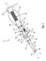
- FIG. 1is a partially transparent elevated view of one embodiment of an insertion device according to the present invention
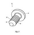
- FIG. 2is an elevated view of a fixation element for use with the insertion device of FIG. 1 ;
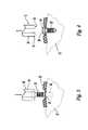
- FIGS. 3-4illustrate the placement of a fixation element within a pre-drilled hole in bone
- FIG. 5is a partially transparent elevated view of another embodiment of an insertion device
- FIG. 6is a partial elevated view of the device of FIG. 5 ;
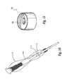
- FIG. 7is a partially transparent elevated view of another embodiment of an insertion device
- FIG. 8a cross-sectional view of the embodiment of FIG. 7 ;
- FIG. 9is a partial cross-sectional view of a portion A of the device of FIG. 8 ;
- FIG. 10is an elevated view of another embodiment of an insertion device
- FIG. 11is an elevated view of a cam member of the device of FIG. 10 .
- a preferred fixation element insertion device 10generally includes a longitudinal member extending along a longitudinal axis 12 from a proximal end 14 to a distal end 16 and having a channel 18 extending therein.
- the insertion deviceis preferably used to drive an osteosynthetic fixation element, such as a resorbable tack, into bone tissue.
- Channel 18is configured and dimensioned to receive at least one fixation element for storage, transport, dispensing, and/or insertion into bone.
- one preferred fixation element compatible with insertion device 10comprises a tack 20 having a shaft 22 integral with a head 24 at a proximal end thereof.
- the distal end of shaft 22has a conical nose 26 to facilitate the insertion of tack 20 into bone tissue.
- a plurality of circular ribs 28extend radially from the exterior of shaft 22 to prevent the removal of the tack from the bone tissue after it has been inserted.
- Head 24has an outer diameter greater than the diameter of shaft 22 and contacts or rests against the bone or bone plate when the tack is inserted into bone tissue.
- the tackis made from a resorbable material so that it remains in the bone tissue temporarily and is absorbed by the body.
- tack 20can have numerously different configurations and dimensions.
- different types of fixation elements altogethercan be used with insertion device 10 .
- biocompatible screws, nails, anchors, rivets, or other similar implantscan also be inserted using insertion device 10 .
- insertion device 10has a handle 30 at the proximal end that is configured to conform to the shape of a person's hand or palm for easily gripping the device and an applicator extension 32 for holding and dispensing the fixation element.
- a central channel 18extends within handle 30 and through extension 32 and is in communication with channel 18 at distal end 16 .
- Channel 18generally comprises a socket defined at the distal end 16 and an elongate applicator extension 32 extends between distal end 16 and handle 30 .
- Extension 32can be a unitary extension or can include multiple parts. Socket or channel 18 fits about the proximal end of fixation element 20 to hold element 20 in insertion device 10 by an interference or friction fit. In the embodiment of FIG.
- an individual tack 20can be held at distal end 16 and head 24 of tack 20 is preferably held within the socket or channel 18 while the shaft 22 of tack 20 projects outside thereof, as shown in FIG. 3 .
- a pronged tip 34for retaining a fixation element. Pronged tip 34 is generally flexible and when the distal end of extension 32 is pressed, the prongs 34 of sleeve 62 flex around the head of a fixation element to pick up and retain the element. In this way, it is possible to pick up a relatively small fixation element in a simple, single action.
- a shaft member 36 and a firing spring 38are housed within the handle 30 .
- Shaft member 36extends longitudinally within handle 30 and extension 32 and is preferably moveable along axis 12 with respect to handle 30 and extension 32 .
- Firing spring 38is positioned at the proximal end of handle 30 and is compressible between a force adjustment dial 39 at proximal end 14 and a proximal end of shaft member 36 , biasing shaft member 36 in a distal direction.
- Shaft 36is generally cylindrical and includes a base portion 42 that slidingly engages the interior of channel 18 within handle 30 , a mid-section 44 having a smaller diameter than base portion 42 , and a tip portion 46 having a smaller diameter than mid-section 44 .
- a first shoulder 43is positioned at the transition of base portion 42 and mid-section 44 and a second shoulder 45 is positioned at the transition of mid-section 44 and tip portion 46 .
- Shaft 36is moveable from a loaded position (shown in FIG. 1 ) to an unloaded position for inserting a fixation element into bone.
- An activation button 48extends within channel 18 for activating the movement of shaft 36 from a loaded position to an unloaded position.
- Button 48is positioned along a portion of handle 30 and partially extends within channel 18 for engaging shaft 36 . Referring to FIG. 1 , when shaft 36 is in the loaded position ledge 49 at the proximal end of button 48 engages second shoulder 45 preventing shaft 36 from moving in the distal direction or to the unloaded position.
- button 48is pivotably positioned about a pin 47 and the distal portion of button 48 is biased radially outward by a spring 50 so that ledge 49 at the proximal portion of button 48 is biased inward toward engagement with shoulder 45 .
- a collar 51is preferably positioned within handle 30 for engaging spring 50 in the radial direction and permitting mid-section 44 of shaft 36 to slide therethrough without engaging spring 50 .
- button 48is depressed, ledge 49 is pivoted radially outward and out of engagement with shoulder.
- different button assemblies or triggering mechanismscan be used.
- a thumb slide 52is positioned along a portion of handle 30 opposite activation button 48 and is moveable in the longitudinal direction for moving shaft 36 from an unloaded to a loaded position. Thumb slide 52 partially extends within channel 18 for engaging shaft 36 and moving shaft 36 in the longitudinal direction. In an unloaded position, shoulder 45 engages an inner ledge 53 of thumb slide 52 and when thumb slide 52 is moved in the proximal direction by an operator, shaft 36 is also retracted. To move shaft 36 to the loaded position, thumb slide 52 is moved in the proximal direction until shoulder 45 slides beyond ledge 49 of button 48 and ledge 49 engages shoulder 45 , thereby locking shaft 36 in the loaded position. This shaft retraction will also compress firing spring 38 .
- a spring 54is housed within handle 30 and biases thumb slide 52 in the distal direction and once shaft 36 is in the loaded position, the thumb slide is released and returns to its resting position. Once shaft 36 is again in the loaded position, another tack can be inserted into the extension 32 .
- the insertion devicecan be used to fasten a plate 56 or other device to a bone 57 .
- a hole 58is pre-drilled in the bone tissue at the desired insertion location and the insertion device 10 is placed adjacent the insertion location and the tack is aligned with hole 58 .
- the activation button 48is depressed to release shaft 36 , and shaft 36 is driven in the distal direction by the force of firing spring 38 thereby driving tack 20 into the bone tissue.
- insertion device 10is withdrawn from the insertion location and tack 20 is separated from channel 18 .
- the forces holding shaft 22 of tack 20 to bone 57are greater than the forces of the interference fit between head 24 and channel 18 so that head 24 of tack 20 is separated from distal end 16 , leaving tack 20 secured to the bone.
- the device 10can then be reloaded by moving the thumb slide in the proximal direction as explained above and inserting another tack into extension 32 . The steps are then repeated for each tack until the plate 56 is adequately secured.
- the thumb slide and activation button configuration of device 10permits a surgeon to cock and fire, or load and unload the device using only one hand.
- insertion device 10is constructed from stainless steel and anodized aluminum and as a result is a reusable device and autoclavable between uses.
- extension applicator 32preferably comprises a stem 60 with a holding sleeve 62 removably attached thereto by a coupling member 64 .
- Holding sleeve 62can be removed and replaced with various sized holding sleeves to accommodate tacks of differing shapes and sizes. In a preferred embodiment, holding sleeve 62 can be easily removed without the need for tools or hardware.
- a force adjustment dial 39is positioned at proximal end 14 of the device 10 and threadably engages handle 30 .
- Dial 39can be rotated and moved in the proximal and distal direction with respect to handle 30 for varying the amount of compression of firing spring 38 and thereby adjusting the amount of force exerted upon shaft 36 and overall force of insertion of tack 20 .
- a force adjustment gauge 66can be inserted in handle 30 for delineating the amount of force applied. For example, a line on a force adjustment gauge can show the relative position between minimum and maximum force settings and be visible through a cutaway in the handle. This feature desirably allows a surgeon to gauge the level of insertion force and adjust according to bone quality and surgeon preference.
- a pair of activation buttons 48can be used instead of a single button. In this embodiment, both buttons must be depressed in order to release shaft 36 , thereby providing a safety feature so that a tack is not accidentally fired. As seen in FIG. 5 , activation buttons 48 are positioned on opposite sides of handle 30 and are offset 90° with respect to thumb slide 52 . Of course, other safety features can also be incorporated into device 10 to prevent accidental firing.
- Insertion device 70includes a handle 72 at a proximal end and a spring loaded elongate applicator extension 74 extending between distal end 76 and handle 72 .
- Extension 74comprises a spring cover 78 attached to handle 72 for housing spring 80 and a holding sleeve 82 coaxially attached to the distal end of spring cover 78 in a telescoping fashion for receiving a fixation element.
- Sleeve 82has slightly smaller external dimensions than the internal dimensions of cover 78 so that the proximal end of sleeve 82 can be inserted into the distal end of cover 78 and sleeve 82 can move in the axial direction with respect to cover 78 .
- sleeve 82can include prongs that interlock with ridges on the interior of cover 78 so that when sleeve 82 is inserted into cover 78 , sleeve 82 is not inadvertently removed from cover 78 in the distal direction.
- sleeve 82has prongs 84 that are flexible and are collapsible or bendable into the interior of sleeve 82 so that sleeve 82 can be removed from cover 78 for cleaning, disassembly, or replacement.
- Prongs 84are biased radially outwardly so that sleeve 82 can be easily reattached by simply pushing the sleeve into the cover in the proximal direction.
- the distal end of sleeve 82preferably has a pronged tip similar to that described previously for retaining a fixation element.
- a central channel 90extends within handle 72 and through extension 74 and houses a firing spring 91 and a shaft member 92 similar to the embodiment of FIG. 1 .
- Firing spring 91is biased between force adjustment dial 93 and the proximal end of shaft 92 .
- Adjustment dial 93includes a knob 100 with internal threading that engages an externally threaded adjustment slider 102 that is slidably housed within channel 90 . When knob 100 is rotated, adjustment slider 102 slidably moves within channel 90 and compresses or decompresses spring 91 for adjusting the amount of force that is exerted on shaft 92 and consequently the tack during insertion.
- a pair of knob retaining screws 104extend radially inward from the exterior of handle 72 and engage a circular groove in knob 100 for retaining knob 100 in the proximal end of handle 72 .
- a guide screw 106extends inward from handle 72 and engage a longitudinal groove in adjustment slider 102 to prevent the slider from rotating.
- Shaft 92extends longitudinally within handle 72 and is generally identical to shaft 36 described above, moving between a loaded and an unloaded position.
- Shaft 92includes a base portion 94 , a mid-section 96 having a smaller diameter than base portion 94 , and a tip portion 98 having a smaller diameter than mid-section 96 .
- a first shoulder 95is positioned at the transition of base portion 94 and mid-section 96 and a second shoulder 97 is positioned at the transition of mid-section 96 and tip portion 98 .
- Device 70includes an activation button 108 similar to button 48 described above for facilitating movement of shaft 92 from the loaded to the unloaded position in the same fashion as described with respect to the embodiment of FIG. 1 .
- insertion device 70preferably has a spring 80 housed within spring cover 78 that biases holding sleeve 82 in the distal direction and once shaft 92 is in the loaded position, the holding sleeve is released and returns to its resting position.
- shaft 92can be easily moved from the unloaded to the loaded position, by depressing device 70 in the distal direction against a solid object, such as a table or a surgeons hand.
- a solid objectsuch as a table or a surgeons hand.
- the method of operation or use of device 70is similar to the method described above with respect to device 10 .
- Insertion device 110has a cam 112 for moving shaft 92 from the unloaded to the loaded position.
- shaft 92has pins 114 extending outwardly therefrom that engage an internal ramp 116 within cam 112 and when cam 112 is rotated pins 114 slide along ramp 116 in the proximal direction and thereby move shaft 92 in the proximal direction and shaft 92 is retracted until shoulder 97 of shaft 92 slides beyond button 108 and the button engages shoulder 97 , thereby locking shaft 92 in the loaded position in a similar fashion to button 48 described above.
- cam 112is rotated to provide clearance for pins 114 to move in the distal direction during the unloading or firing movement of shaft 92 .
Landscapes
- Health & Medical Sciences (AREA)
- Engineering & Computer Science (AREA)
- Life Sciences & Earth Sciences (AREA)
- Surgery (AREA)
- Mechanical Engineering (AREA)
- Orthopedic Medicine & Surgery (AREA)
- Heart & Thoracic Surgery (AREA)
- Biomedical Technology (AREA)
- Nuclear Medicine, Radiotherapy & Molecular Imaging (AREA)
- Medical Informatics (AREA)
- Molecular Biology (AREA)
- Animal Behavior & Ethology (AREA)
- General Health & Medical Sciences (AREA)
- Public Health (AREA)
- Veterinary Medicine (AREA)
- Surgical Instruments (AREA)
Abstract
Description
Claims (14)
Priority Applications (1)
| Application Number | Priority Date | Filing Date | Title |
|---|---|---|---|
| US10/992,259US8052691B2 (en) | 2001-05-30 | 2004-11-18 | Spring loaded fixation element insertion device |
Applications Claiming Priority (6)
| Application Number | Priority Date | Filing Date | Title |
|---|---|---|---|
| US09/866,841US7147641B2 (en) | 2001-05-30 | 2001-05-30 | Fixation element insertion device |
| US33097701P | 2001-11-05 | 2001-11-05 | |
| PCT/US2002/016656WO2002096310A1 (en) | 2001-05-30 | 2002-05-28 | Insertion device for bone fixation elements |
| WOPCT/US02/16656 | 2002-05-28 | ||
| US10/287,693US20030125750A1 (en) | 2001-11-05 | 2002-11-05 | Spring loaded fixation element insertion device |
| US10/992,259US8052691B2 (en) | 2001-05-30 | 2004-11-18 | Spring loaded fixation element insertion device |
Related Parent Applications (1)
| Application Number | Title | Priority Date | Filing Date |
|---|---|---|---|
| US10/287,693ContinuationUS20030125750A1 (en) | 2001-05-30 | 2002-11-05 | Spring loaded fixation element insertion device |
Publications (2)
| Publication Number | Publication Date |
|---|---|
| US20050070918A1 US20050070918A1 (en) | 2005-03-31 |
| US8052691B2true US8052691B2 (en) | 2011-11-08 |
Family
ID=26964599
Family Applications (2)
| Application Number | Title | Priority Date | Filing Date |
|---|---|---|---|
| US10/287,693AbandonedUS20030125750A1 (en) | 2001-05-30 | 2002-11-05 | Spring loaded fixation element insertion device |
| US10/992,259Expired - Fee RelatedUS8052691B2 (en) | 2001-05-30 | 2004-11-18 | Spring loaded fixation element insertion device |
Family Applications Before (1)
| Application Number | Title | Priority Date | Filing Date |
|---|---|---|---|
| US10/287,693AbandonedUS20030125750A1 (en) | 2001-05-30 | 2002-11-05 | Spring loaded fixation element insertion device |
Country Status (1)
| Country | Link |
|---|---|
| US (2) | US20030125750A1 (en) |
Cited By (5)
| Publication number | Priority date | Publication date | Assignee | Title |
|---|---|---|---|---|
| US8603102B2 (en) | 2009-05-26 | 2013-12-10 | Zimmer, Inc. | Bone fixation tool |
| US20140046362A1 (en)* | 2012-08-07 | 2014-02-13 | Zift Medical | Tissue Attachment Device And Method |
| US9987067B2 (en) | 2012-07-11 | 2018-06-05 | Zimmer, Inc. | Bone fixation tool |
| US10179017B2 (en) | 2014-04-03 | 2019-01-15 | Zimmer, Inc. | Orthopedic tool for bone fixation |
| US12059189B2 (en) | 2020-06-17 | 2024-08-13 | Arthrex, Inc. | Compression/reduction drivers for performing surgical methods |
Families Citing this family (47)
| Publication number | Priority date | Publication date | Assignee | Title |
|---|---|---|---|---|
| US6648888B1 (en)* | 2002-09-06 | 2003-11-18 | Endius Incorporated | Surgical instrument for moving a vertebra |
| US7887539B2 (en) | 2003-01-24 | 2011-02-15 | Depuy Spine, Inc. | Spinal rod approximators |
| US7988698B2 (en)* | 2003-01-28 | 2011-08-02 | Depuy Spine, Inc. | Spinal rod approximator |
| US20040267275A1 (en)* | 2003-06-26 | 2004-12-30 | Cournoyer John R. | Spinal implant holder and rod reduction systems and methods |
| US20050059969A1 (en)* | 2003-09-17 | 2005-03-17 | Depuy Acromed, Inc. | Rod approximator |
| US7588588B2 (en) | 2003-10-21 | 2009-09-15 | Innovative Spinal Technologies | System and method for stabilizing of internal structures |
| US7967826B2 (en)* | 2003-10-21 | 2011-06-28 | Theken Spine, Llc | Connector transfer tool for internal structure stabilization systems |
| US7588575B2 (en)* | 2003-10-21 | 2009-09-15 | Innovative Spinal Technologies | Extension for use with stabilization systems for internal structures |
| US7766920B2 (en)* | 2003-11-26 | 2010-08-03 | Synthes Usa, Llc | Cannulated fastener system |
| ATE441376T1 (en)* | 2003-12-17 | 2009-09-15 | Depuy Spine Inc | INSTRUMENTS AND PROCEDURES FOR BONE ANCHOR PROCEDURES AND SPINAL BAR REDUCTION |
| US7842044B2 (en) | 2003-12-17 | 2010-11-30 | Depuy Spine, Inc. | Instruments and methods for bone anchor engagement and spinal rod reduction |
| US7604643B2 (en)* | 2004-04-06 | 2009-10-20 | Synthes Usa, Llc | Adjustable tool for cannulated fasteners |
| US7569061B2 (en) | 2004-11-16 | 2009-08-04 | Innovative Spinal Technologies, Inc. | Off-axis anchor guidance system |
| US7951175B2 (en) | 2005-03-04 | 2011-05-31 | Depuy Spine, Inc. | Instruments and methods for manipulating a vertebra |
| US7951172B2 (en) | 2005-03-04 | 2011-05-31 | Depuy Spine Sarl | Constrained motion bone screw assembly |
| US20060293692A1 (en) | 2005-06-02 | 2006-12-28 | Whipple Dale E | Instruments and methods for manipulating a spinal fixation element |
| US7572264B2 (en) | 2005-06-28 | 2009-08-11 | Warsaw Orthopedic, Inc. | Driver instrument for use in a surgical application |
| US20070161998A1 (en)* | 2005-10-28 | 2007-07-12 | Dale Whipple | Instruments and Methods For Manipulating A Spinal Rod |
| US7833248B2 (en)* | 2006-03-10 | 2010-11-16 | Custom Spine, Inc. | Spinal cross-connector |
| US7780704B2 (en)* | 2006-03-10 | 2010-08-24 | Custom Spine, Inc. | Spinal cross-connector |
| EP1878398B1 (en)* | 2006-07-14 | 2009-06-17 | Stryker Trauma GmbH | A medical device and kit for handling an implant |
| US7992878B2 (en)* | 2006-07-31 | 2011-08-09 | Warsaw Orthopedic, Inc | Helical lead for a drive shaft collet |
| WO2008021972A2 (en)* | 2006-08-10 | 2008-02-21 | Pioneer Surgical Technology, Inc. | Intervertebral disc space sizing tools and methods |
| US8758367B2 (en)* | 2006-09-05 | 2014-06-24 | Smith & Nephew, Inc. | Anchor delivery system |
| US8845652B2 (en)* | 2007-02-27 | 2014-09-30 | Warsaw Orthopedic, Inc. | Surgical driver |
| US8172847B2 (en)* | 2007-03-29 | 2012-05-08 | Depuy Spine, Inc. | In-line rod reduction device and methods |
| WO2008122446A1 (en)* | 2007-04-10 | 2008-10-16 | Stryker Trauma Gmbh | Bone screw holding device |
| US20080275459A1 (en)* | 2007-05-02 | 2008-11-06 | Charles Anthony Dickinson | Surgical instrument attachment mechanism |
| US7887541B2 (en)* | 2007-07-26 | 2011-02-15 | Depuy Spine, Inc. | Spinal rod reduction instruments and methods for use |
| US8790348B2 (en) | 2007-09-28 | 2014-07-29 | Depuy Spine, Inc. | Dual pivot instrument for reduction of a fixation element and method of use |
| US8608746B2 (en) | 2008-03-10 | 2013-12-17 | DePuy Synthes Products, LLC | Derotation instrument with reduction functionality |
| US8709015B2 (en) | 2008-03-10 | 2014-04-29 | DePuy Synthes Products, LLC | Bilateral vertebral body derotation system |
| US10973556B2 (en) | 2008-06-17 | 2021-04-13 | DePuy Synthes Products, Inc. | Adjustable implant assembly |
| EP2160986B1 (en)* | 2008-09-05 | 2011-05-18 | BrainLAB AG | Device for attaching a marker device to a bone |
| WO2010065545A1 (en)* | 2008-12-01 | 2010-06-10 | Pioneer Surgical Technology, Inc | Intervertebral disc space sizing tools and methods |
| US8206394B2 (en) | 2009-05-13 | 2012-06-26 | Depuy Spine, Inc. | Torque limited instrument for manipulating a spinal rod relative to a bone anchor |
| US8545505B2 (en)* | 2010-01-15 | 2013-10-01 | Pioneer Surgical Technology, Inc. | Low friction rod persuader |
| US9539069B2 (en) | 2012-04-26 | 2017-01-10 | Zimmer Dental, Inc. | Dental implant wedges |
| US9554877B2 (en) | 2012-07-31 | 2017-01-31 | Zimmer, Inc. | Dental regenerative device made of porous metal |
| WO2019051260A1 (en) | 2017-09-08 | 2019-03-14 | Pioneer Surgical Technology, Inc. | Intervertebral implants, instruments, and methods |
| USD907771S1 (en) | 2017-10-09 | 2021-01-12 | Pioneer Surgical Technology, Inc. | Intervertebral implant |
| US10966762B2 (en) | 2017-12-15 | 2021-04-06 | Medos International Sarl | Unilateral implant holders and related methods |
| KR101922141B1 (en)* | 2018-10-30 | 2019-02-13 | 주식회사 엠씨티바이오 | Fixed screw launcher for membrane |
| USD1004774S1 (en) | 2019-03-21 | 2023-11-14 | Medos International Sarl | Kerrison rod reducer |
| US11291482B2 (en) | 2019-03-21 | 2022-04-05 | Medos International Sarl | Rod reducers and related methods |
| US11291481B2 (en) | 2019-03-21 | 2022-04-05 | Medos International Sarl | Rod reducers and related methods |
| EP4240262B1 (en) | 2020-11-09 | 2024-12-04 | Medos International Sàrl | Biplanar forceps reducers |
Citations (47)
| Publication number | Priority date | Publication date | Assignee | Title |
|---|---|---|---|---|
| US1572046A (en)* | 1923-12-21 | 1926-02-09 | Adam J Seiler | Impression-making tool |
| US1952395A (en)* | 1932-09-15 | 1934-03-27 | American Optical Corp | Screw setting device |
| US2212339A (en)* | 1936-10-27 | 1940-08-20 | Arthur V Cullen | Device for applying fastening means |
| US2257979A (en)* | 1939-12-23 | 1941-10-07 | Globe Union Inc | Combined shaft bearing and coupling |
| US3010193A (en)* | 1959-02-17 | 1961-11-28 | Burroughs Corp | Assembly tool |
| US4129975A (en)* | 1977-03-09 | 1978-12-19 | Matrix Toys, Inc. | Construction set having clip fasteners |
| DE2933141A1 (en) | 1978-10-06 | 1980-04-10 | Sulzer Ag | ANCHORING PIN FOR BONE IMPLANTS |
| US4402641A (en) | 1980-04-17 | 1983-09-06 | Itw Ateco Gmbh | Self centering fastener |
| US4441563A (en)* | 1981-11-02 | 1984-04-10 | Black & Decker Inc. | Tool collet and control means |
| US4708209A (en)* | 1985-08-12 | 1987-11-24 | Aspinwall Hugh M | Manually operated impact driver |
| US4776739A (en) | 1986-04-14 | 1988-10-11 | Illinois Tool Works Inc. | Plastic drive fastener |
| US4776328A (en) | 1986-04-15 | 1988-10-11 | Sulzer Brothers Limited | Bone nail and an instrument for implanting a bone nail |
| US4928560A (en)* | 1989-02-02 | 1990-05-29 | Bang Kook B | Power driven screw driver |
| US4963144A (en) | 1989-03-17 | 1990-10-16 | Huene Donald R | Bone screw fixation assembly, bone screw therefor and method of fixation |
| US5071420A (en) | 1991-04-25 | 1991-12-10 | Depuy Du Pont Orthopaedics | Isometry testing device |
| US5139499A (en) | 1989-02-06 | 1992-08-18 | American Cyanamid Company | Screw and driver |
| FR2682587A1 (en) | 1991-10-21 | 1993-04-23 | Laboureau Jacques Philippe | LIGAMENTARY SURGICAL NAIL AND ASSOCIATED ANCILLARY INTRUMENTATION. |
| US5236431A (en) | 1991-07-22 | 1993-08-17 | Synthes | Resorbable fixation device with controlled stiffness for treating bodily material in vivo and introducer therefor |
| US5258016A (en) | 1990-07-13 | 1993-11-02 | American Cyanamid Company | Suture anchor and driver assembly |
| US5261914A (en) | 1987-09-02 | 1993-11-16 | Russell Warren | Surgical fastener |
| US5268001A (en) | 1990-09-25 | 1993-12-07 | Innovasive Devices, Inc. | Bone fastener |
| US5391170A (en) | 1991-12-13 | 1995-02-21 | David A. McGuire | Angled surgical screw driver and methods of arthroscopic ligament reconstruction |
| US5398861A (en)* | 1993-04-16 | 1995-03-21 | United States Surgical Corporation | Device for driving surgical fasteners |
| US5431660A (en)* | 1993-11-30 | 1995-07-11 | Burke; Dennis W. | Spring loaded screw and driver/extractor therefor |
| US5445641A (en) | 1991-05-10 | 1995-08-29 | Synthes | Storage and dispensing device for osteosynthetic fixation elements |
| US5522843A (en) | 1994-02-23 | 1996-06-04 | Orthopaedic Biosystems Limited, Inc. | Apparatus for attaching soft tissue to bone |
| US5578057A (en) | 1993-07-28 | 1996-11-26 | Mitek Surgical Products, Inc. | Anchoring device installation tool assembly and method |
| US5584860A (en) | 1995-02-15 | 1996-12-17 | Mitek Surgical Products, Inc. | Suture anchor loader and driver |
| US5590574A (en) | 1995-09-05 | 1997-01-07 | Lide; Thomas E. | Driver with automatic fastener feed |
| US5672038A (en) | 1995-11-20 | 1997-09-30 | Ford Global Technologies, Inc. | Fastener |
| US5683401A (en) | 1994-02-17 | 1997-11-04 | Arthrex, Inc. | Method and apparatus for installing a suture anchor through a hollow cannulated grasper |
| US5735854A (en) | 1996-04-12 | 1998-04-07 | Caron; Philippe | Device for applying a screw |
| EP0834281A1 (en) | 1996-10-03 | 1998-04-08 | United States Surgical Corporation | System for suture anchor placement |
| US5741268A (en) | 1995-03-18 | 1998-04-21 | Schuetz; Frank-Ullrich | Tacking device and tacking nails for surgery |
| US5800109A (en) | 1997-05-13 | 1998-09-01 | Amifast Corporation | Fastener with a tapered section and a slot |
| US5814051A (en) | 1997-06-06 | 1998-09-29 | Mitex Surgical Products, Inc. | Suture anchor insertion system |
| US5893856A (en) | 1996-06-12 | 1999-04-13 | Mitek Surgical Products, Inc. | Apparatus and method for binding a first layer of material to a second layer of material |
| US5895396A (en) | 1995-06-15 | 1999-04-20 | Ethicon, Inc. | Surgical pins |
| US5901424A (en) | 1997-05-29 | 1999-05-11 | Rector; Charles W. | Trocar button |
| US5904685A (en) | 1997-04-11 | 1999-05-18 | Stryker Corporation | Screw sheath |
| US5906624A (en) | 1997-01-03 | 1999-05-25 | Mitek Surgical Products, Inc. | Suture threader assembly, suture anchor assembly, and method for threading suture |
| FR2777443A1 (en) | 1998-04-21 | 1999-10-22 | Tornier Sa | Ancillary instrument for fitting and removing an implant such as a suture anchor |
| US6007539A (en) | 1996-01-17 | 1999-12-28 | Axel Kirsch | Fastening nail |
| EP1090591A2 (en) | 1999-09-29 | 2001-04-11 | Ethicon, Inc. | Absorbable rivet/pin applier for use in surgical procedures |
| US6273893B1 (en)* | 1999-11-10 | 2001-08-14 | Ethicon, Inc. | Absorbable rivet/pin applier for use in surgical procedures |
| US6402759B1 (en)* | 1998-12-11 | 2002-06-11 | Biohorizons Implant Systems, Inc. | Surgical fastener driver |
| US7147641B2 (en)* | 2001-05-30 | 2006-12-12 | Chen Michael C | Fixation element insertion device |
Family Cites Families (4)
| Publication number | Priority date | Publication date | Assignee | Title |
|---|---|---|---|---|
| NL237357A (en)* | 1958-03-27 | |||
| US4549538A (en)* | 1982-11-12 | 1985-10-29 | Zimmer, Inc. | Pin inserter sheath |
| US6386078B1 (en)* | 1999-03-30 | 2002-05-14 | Shu Te Wu | Screwdriver for operating self-tightening screw |
| TW467010U (en)* | 2000-08-14 | 2001-12-01 | Shu-Te Wu | Hammer with a pre-nailed device for pointed fasteners |
- 2002
- 2002-11-05USUS10/287,693patent/US20030125750A1/ennot_activeAbandoned
- 2004
- 2004-11-18USUS10/992,259patent/US8052691B2/ennot_activeExpired - Fee Related
Patent Citations (49)
| Publication number | Priority date | Publication date | Assignee | Title |
|---|---|---|---|---|
| US1572046A (en)* | 1923-12-21 | 1926-02-09 | Adam J Seiler | Impression-making tool |
| US1952395A (en)* | 1932-09-15 | 1934-03-27 | American Optical Corp | Screw setting device |
| US2212339A (en)* | 1936-10-27 | 1940-08-20 | Arthur V Cullen | Device for applying fastening means |
| US2257979A (en)* | 1939-12-23 | 1941-10-07 | Globe Union Inc | Combined shaft bearing and coupling |
| US3010193A (en)* | 1959-02-17 | 1961-11-28 | Burroughs Corp | Assembly tool |
| US4129975A (en)* | 1977-03-09 | 1978-12-19 | Matrix Toys, Inc. | Construction set having clip fasteners |
| DE2933141A1 (en) | 1978-10-06 | 1980-04-10 | Sulzer Ag | ANCHORING PIN FOR BONE IMPLANTS |
| US4402641A (en) | 1980-04-17 | 1983-09-06 | Itw Ateco Gmbh | Self centering fastener |
| US4441563A (en)* | 1981-11-02 | 1984-04-10 | Black & Decker Inc. | Tool collet and control means |
| US4708209A (en)* | 1985-08-12 | 1987-11-24 | Aspinwall Hugh M | Manually operated impact driver |
| US4776739A (en) | 1986-04-14 | 1988-10-11 | Illinois Tool Works Inc. | Plastic drive fastener |
| US4776328A (en) | 1986-04-15 | 1988-10-11 | Sulzer Brothers Limited | Bone nail and an instrument for implanting a bone nail |
| US5261914A (en) | 1987-09-02 | 1993-11-16 | Russell Warren | Surgical fastener |
| US4928560A (en)* | 1989-02-02 | 1990-05-29 | Bang Kook B | Power driven screw driver |
| US5139499A (en) | 1989-02-06 | 1992-08-18 | American Cyanamid Company | Screw and driver |
| US4963144A (en) | 1989-03-17 | 1990-10-16 | Huene Donald R | Bone screw fixation assembly, bone screw therefor and method of fixation |
| US5258016A (en) | 1990-07-13 | 1993-11-02 | American Cyanamid Company | Suture anchor and driver assembly |
| US5268001A (en) | 1990-09-25 | 1993-12-07 | Innovasive Devices, Inc. | Bone fastener |
| US5071420A (en) | 1991-04-25 | 1991-12-10 | Depuy Du Pont Orthopaedics | Isometry testing device |
| US5445641A (en) | 1991-05-10 | 1995-08-29 | Synthes | Storage and dispensing device for osteosynthetic fixation elements |
| US5236431A (en) | 1991-07-22 | 1993-08-17 | Synthes | Resorbable fixation device with controlled stiffness for treating bodily material in vivo and introducer therefor |
| FR2682587A1 (en) | 1991-10-21 | 1993-04-23 | Laboureau Jacques Philippe | LIGAMENTARY SURGICAL NAIL AND ASSOCIATED ANCILLARY INTRUMENTATION. |
| US5391170A (en) | 1991-12-13 | 1995-02-21 | David A. McGuire | Angled surgical screw driver and methods of arthroscopic ligament reconstruction |
| US5398861A (en)* | 1993-04-16 | 1995-03-21 | United States Surgical Corporation | Device for driving surgical fasteners |
| US5578057A (en) | 1993-07-28 | 1996-11-26 | Mitek Surgical Products, Inc. | Anchoring device installation tool assembly and method |
| US5431660A (en)* | 1993-11-30 | 1995-07-11 | Burke; Dennis W. | Spring loaded screw and driver/extractor therefor |
| US5683401A (en) | 1994-02-17 | 1997-11-04 | Arthrex, Inc. | Method and apparatus for installing a suture anchor through a hollow cannulated grasper |
| US5522843A (en) | 1994-02-23 | 1996-06-04 | Orthopaedic Biosystems Limited, Inc. | Apparatus for attaching soft tissue to bone |
| US5720766A (en) | 1994-02-23 | 1998-02-24 | Orthopaedic Biosystems Limited, Inc. | Apparatus for attaching soft tissue to bone |
| US5584860A (en) | 1995-02-15 | 1996-12-17 | Mitek Surgical Products, Inc. | Suture anchor loader and driver |
| US5741268A (en) | 1995-03-18 | 1998-04-21 | Schuetz; Frank-Ullrich | Tacking device and tacking nails for surgery |
| US5895396A (en) | 1995-06-15 | 1999-04-20 | Ethicon, Inc. | Surgical pins |
| US5590574A (en) | 1995-09-05 | 1997-01-07 | Lide; Thomas E. | Driver with automatic fastener feed |
| US5672038A (en) | 1995-11-20 | 1997-09-30 | Ford Global Technologies, Inc. | Fastener |
| US6007539A (en) | 1996-01-17 | 1999-12-28 | Axel Kirsch | Fastening nail |
| US5735854A (en) | 1996-04-12 | 1998-04-07 | Caron; Philippe | Device for applying a screw |
| US5893856A (en) | 1996-06-12 | 1999-04-13 | Mitek Surgical Products, Inc. | Apparatus and method for binding a first layer of material to a second layer of material |
| EP0834281A1 (en) | 1996-10-03 | 1998-04-08 | United States Surgical Corporation | System for suture anchor placement |
| US5906624A (en) | 1997-01-03 | 1999-05-25 | Mitek Surgical Products, Inc. | Suture threader assembly, suture anchor assembly, and method for threading suture |
| US5904685A (en) | 1997-04-11 | 1999-05-18 | Stryker Corporation | Screw sheath |
| US5800109A (en) | 1997-05-13 | 1998-09-01 | Amifast Corporation | Fastener with a tapered section and a slot |
| US5901424A (en) | 1997-05-29 | 1999-05-11 | Rector; Charles W. | Trocar button |
| US5814051A (en) | 1997-06-06 | 1998-09-29 | Mitex Surgical Products, Inc. | Suture anchor insertion system |
| FR2777443A1 (en) | 1998-04-21 | 1999-10-22 | Tornier Sa | Ancillary instrument for fitting and removing an implant such as a suture anchor |
| US6402759B1 (en)* | 1998-12-11 | 2002-06-11 | Biohorizons Implant Systems, Inc. | Surgical fastener driver |
| EP1090591A2 (en) | 1999-09-29 | 2001-04-11 | Ethicon, Inc. | Absorbable rivet/pin applier for use in surgical procedures |
| EP1090591A3 (en) | 1999-09-29 | 2001-06-06 | Ethicon, Inc. | Absorbable rivet/pin applier for use in surgical procedures |
| US6273893B1 (en)* | 1999-11-10 | 2001-08-14 | Ethicon, Inc. | Absorbable rivet/pin applier for use in surgical procedures |
| US7147641B2 (en)* | 2001-05-30 | 2006-12-12 | Chen Michael C | Fixation element insertion device |
Cited By (7)
| Publication number | Priority date | Publication date | Assignee | Title |
|---|---|---|---|---|
| US8603102B2 (en) | 2009-05-26 | 2013-12-10 | Zimmer, Inc. | Bone fixation tool |
| US8852202B2 (en) | 2009-05-26 | 2014-10-07 | Zimmer, Inc. | Bone fixation tool |
| US9987067B2 (en) | 2012-07-11 | 2018-06-05 | Zimmer, Inc. | Bone fixation tool |
| US20140046362A1 (en)* | 2012-08-07 | 2014-02-13 | Zift Medical | Tissue Attachment Device And Method |
| US20160206081A1 (en)* | 2012-08-07 | 2016-07-21 | Zift Medical, LLC | Tissue Attachment Device And Method |
| US10179017B2 (en) | 2014-04-03 | 2019-01-15 | Zimmer, Inc. | Orthopedic tool for bone fixation |
| US12059189B2 (en) | 2020-06-17 | 2024-08-13 | Arthrex, Inc. | Compression/reduction drivers for performing surgical methods |
Also Published As
| Publication number | Publication date |
|---|---|
| US20030125750A1 (en) | 2003-07-03 |
| US20050070918A1 (en) | 2005-03-31 |
Similar Documents
| Publication | Publication Date | Title |
|---|---|---|
| US8052691B2 (en) | Spring loaded fixation element insertion device | |
| US7147641B2 (en) | Fixation element insertion device | |
| US11457967B2 (en) | Driver instruments and related methods | |
| US10709488B2 (en) | Biceps tenodesis delivery tools | |
| JP4159748B2 (en) | Fracture fixation system | |
| US7922724B2 (en) | Rod reducer | |
| US20160302838A1 (en) | Devices and methods for breaking and retaining surgical reduction tabs | |
| US7326198B2 (en) | Remote release instrument holder for surgical use | |
| US20160113643A1 (en) | Biceps Tenodesis Implants and Delivery Tools | |
| EP1014865B1 (en) | Device for driving a needle and meniscal repair | |
| KR20120036310A (en) | Internal cable fixator | |
| EP1878398B1 (en) | A medical device and kit for handling an implant | |
| CA2448676C (en) | Insertion device for bone fixation elements | |
| US11517362B2 (en) | Self-retaining screw and screwdriver | |
| HK1059872B (en) | Insertion device for bone fixation elements | |
| CN110584769A (en) | Gun type reduction forceps and instrument bag | |
| US20170135736A1 (en) | Surgical wrench | |
| HK1029726A1 (en) | Device for driving a needle and meniscal repair | |
| HK1029726B (en) | Device for driving a needle and meniscal repair |
Legal Events
| Date | Code | Title | Description |
|---|---|---|---|
| AS | Assignment | Owner name:SYNTHES (U.S.A.), PENNSYLVANIA Free format text:ASSIGNMENT OF ASSIGNORS INTEREST;ASSIGNORS:ZWIRNMANN, RALPH;CHEN, MICHAEL C.;REEL/FRAME:019623/0694;SIGNING DATES FROM 20030103 TO 20030121 Owner name:SYNTHES (U.S.A.), PENNSYLVANIA Free format text:ASSIGNMENT OF ASSIGNORS INTEREST;ASSIGNORS:ZWIRNMANN, RALPH;CHEN, MICHAEL C.;SIGNING DATES FROM 20030103 TO 20030121;REEL/FRAME:019623/0694 | |
| AS | Assignment | Owner name:SYNTHES USA, LLC, PENNSYLVANIA Free format text:CHANGE OF NAME;ASSIGNOR:SYNTHES (U.S.A.);REEL/FRAME:022214/0552 Effective date:20081223 Owner name:SYNTHES USA, LLC,PENNSYLVANIA Free format text:CHANGE OF NAME;ASSIGNOR:SYNTHES (U.S.A.);REEL/FRAME:022214/0552 Effective date:20081223 | |
| ZAAA | Notice of allowance and fees due | Free format text:ORIGINAL CODE: NOA | |
| ZAAB | Notice of allowance mailed | Free format text:ORIGINAL CODE: MN/=. | |
| STCF | Information on status: patent grant | Free format text:PATENTED CASE | |
| FEPP | Fee payment procedure | Free format text:PAYOR NUMBER ASSIGNED (ORIGINAL EVENT CODE: ASPN); ENTITY STATUS OF PATENT OWNER: LARGE ENTITY | |
| CC | Certificate of correction | ||
| FPAY | Fee payment | Year of fee payment:4 | |
| MAFP | Maintenance fee payment | Free format text:PAYMENT OF MAINTENANCE FEE, 8TH YEAR, LARGE ENTITY (ORIGINAL EVENT CODE: M1552); ENTITY STATUS OF PATENT OWNER: LARGE ENTITY Year of fee payment:8 | |
| FEPP | Fee payment procedure | Free format text:MAINTENANCE FEE REMINDER MAILED (ORIGINAL EVENT CODE: REM.); ENTITY STATUS OF PATENT OWNER: LARGE ENTITY | |
| LAPS | Lapse for failure to pay maintenance fees | Free format text:PATENT EXPIRED FOR FAILURE TO PAY MAINTENANCE FEES (ORIGINAL EVENT CODE: EXP.); ENTITY STATUS OF PATENT OWNER: LARGE ENTITY | |
| STCH | Information on status: patent discontinuation | Free format text:PATENT EXPIRED DUE TO NONPAYMENT OF MAINTENANCE FEES UNDER 37 CFR 1.362 | |
| FP | Lapsed due to failure to pay maintenance fee | Effective date:20231108 |