US8052629B2 - Multi-fit orthotic and mobility assistance apparatus - Google Patents
Multi-fit orthotic and mobility assistance apparatusDownload PDFInfo
- Publication number
- US8052629B2 US8052629B2US12/366,998US36699809AUS8052629B2US 8052629 B2US8052629 B2US 8052629B2US 36699809 AUS36699809 AUS 36699809AUS 8052629 B2US8052629 B2US 8052629B2
- Authority
- US
- United States
- Prior art keywords
- textile
- orthotic
- subject
- thigh
- suspension
- Prior art date
- Legal status (The legal status is an assumption and is not a legal conclusion. Google has not performed a legal analysis and makes no representation as to the accuracy of the status listed.)
- Active, expires
Links
- 239000004753textileSubstances0.000claimsabstractdescription53
- 210000000689upper legAnatomy0.000claimsabstractdescription40
- 239000000725suspensionSubstances0.000claimsabstractdescription24
- 210000002414legAnatomy0.000claimsabstractdescription23
- 210000001699lower legAnatomy0.000claimsabstractdescription23
- 210000003127kneeAnatomy0.000claimsabstractdescription18
- 210000002303tibiaAnatomy0.000claimsdescription34
- 210000000629knee jointAnatomy0.000claimsdescription2
- 244000309466calfSpecies0.000abstractdescription3
- 230000008878couplingEffects0.000abstractdescription2
- 238000010168coupling processMethods0.000abstractdescription2
- 238000005859coupling reactionMethods0.000abstractdescription2
- 230000037230mobilityEffects0.000description11
- 238000013461designMethods0.000description7
- 210000002683footAnatomy0.000description6
- 208000027418Wounds and injuryDiseases0.000description5
- 230000006378damageEffects0.000description5
- 208000014674injuryDiseases0.000description5
- 206010034701Peroneal nerve palsyDiseases0.000description4
- 239000004744fabricSubstances0.000description4
- 210000003423ankleAnatomy0.000description3
- 238000010586diagramMethods0.000description3
- 239000000463materialSubstances0.000description3
- 210000004744fore-footAnatomy0.000description2
- 238000000034methodMethods0.000description2
- 210000003205muscleAnatomy0.000description2
- 238000002560therapeutic procedureMethods0.000description2
- 238000012546transferMethods0.000description2
- 229920000049Carbon (fiber)Polymers0.000description1
- 208000017667Chronic DiseaseDiseases0.000description1
- 206010028289Muscle atrophyDiseases0.000description1
- 208000002193PainDiseases0.000description1
- 241001272996Polyphylla fulloSpecies0.000description1
- 208000004550Postoperative PainDiseases0.000description1
- 229910000831SteelInorganic materials0.000description1
- XAGFODPZIPBFFR-UHFFFAOYSA-NaluminiumChemical compound[Al]XAGFODPZIPBFFR-UHFFFAOYSA-N0.000description1
- 229910052782aluminiumInorganic materials0.000description1
- 230000001174ascending effectEffects0.000description1
- 230000017531blood circulationEffects0.000description1
- 239000004917carbon fiberSubstances0.000description1
- 238000011161developmentMethods0.000description1
- 201000010099diseaseDiseases0.000description1
- 208000037265diseases, disorders, signs and symptomsDiseases0.000description1
- 230000009977dual effectEffects0.000description1
- 210000003414extremityAnatomy0.000description1
- 239000011152fibreglassSubstances0.000description1
- 229920002457flexible plasticPolymers0.000description1
- 230000005021gaitEffects0.000description1
- 230000005484gravityEffects0.000description1
- 230000001771impaired effectEffects0.000description1
- 230000010354integrationEffects0.000description1
- 238000002955isolationMethods0.000description1
- 238000004519manufacturing processMethods0.000description1
- VNWKTOKETHGBQD-UHFFFAOYSA-NmethaneChemical compoundCVNWKTOKETHGBQD-UHFFFAOYSA-N0.000description1
- 230000020763muscle atrophyEffects0.000description1
- 201000000585muscular atrophyDiseases0.000description1
- 210000004417patellaAnatomy0.000description1
- 238000011084recoveryMethods0.000description1
- 230000002441reversible effectEffects0.000description1
- 239000007787solidSubstances0.000description1
- 230000000087stabilizing effectEffects0.000description1
- 239000010959steelSubstances0.000description1
- 238000001356surgical procedureMethods0.000description1
- 238000012549trainingMethods0.000description1
Images


Classifications
- A—HUMAN NECESSITIES
- A61—MEDICAL OR VETERINARY SCIENCE; HYGIENE
- A61F—FILTERS IMPLANTABLE INTO BLOOD VESSELS; PROSTHESES; DEVICES PROVIDING PATENCY TO, OR PREVENTING COLLAPSING OF, TUBULAR STRUCTURES OF THE BODY, e.g. STENTS; ORTHOPAEDIC, NURSING OR CONTRACEPTIVE DEVICES; FOMENTATION; TREATMENT OR PROTECTION OF EYES OR EARS; BANDAGES, DRESSINGS OR ABSORBENT PADS; FIRST-AID KITS
- A61F5/00—Orthopaedic methods or devices for non-surgical treatment of bones or joints; Nursing devices ; Anti-rape devices
- A61F5/01—Orthopaedic devices, e.g. long-term immobilising or pressure directing devices for treating broken or deformed bones such as splints, casts or braces
- A61F5/0102—Orthopaedic devices, e.g. long-term immobilising or pressure directing devices for treating broken or deformed bones such as splints, casts or braces specially adapted for correcting deformities of the limbs or for supporting them; Ortheses, e.g. with articulations
- A61F5/0123—Orthopaedic devices, e.g. long-term immobilising or pressure directing devices for treating broken or deformed bones such as splints, casts or braces specially adapted for correcting deformities of the limbs or for supporting them; Ortheses, e.g. with articulations for the knees
- A61F5/0125—Orthopaedic devices, e.g. long-term immobilising or pressure directing devices for treating broken or deformed bones such as splints, casts or braces specially adapted for correcting deformities of the limbs or for supporting them; Ortheses, e.g. with articulations for the knees the device articulating around a single pivot-point
- A—HUMAN NECESSITIES
- A61—MEDICAL OR VETERINARY SCIENCE; HYGIENE
- A61F—FILTERS IMPLANTABLE INTO BLOOD VESSELS; PROSTHESES; DEVICES PROVIDING PATENCY TO, OR PREVENTING COLLAPSING OF, TUBULAR STRUCTURES OF THE BODY, e.g. STENTS; ORTHOPAEDIC, NURSING OR CONTRACEPTIVE DEVICES; FOMENTATION; TREATMENT OR PROTECTION OF EYES OR EARS; BANDAGES, DRESSINGS OR ABSORBENT PADS; FIRST-AID KITS
- A61F5/00—Orthopaedic methods or devices for non-surgical treatment of bones or joints; Nursing devices ; Anti-rape devices
- A61F5/01—Orthopaedic devices, e.g. long-term immobilising or pressure directing devices for treating broken or deformed bones such as splints, casts or braces
- A61F5/0102—Orthopaedic devices, e.g. long-term immobilising or pressure directing devices for treating broken or deformed bones such as splints, casts or braces specially adapted for correcting deformities of the limbs or for supporting them; Ortheses, e.g. with articulations
Definitions
- At least certain embodiments of the inventionrelate generally to functional rehabilitation and mobility enhancement of patients who have suffered loss of function due to injury, disease or other condition, and more particularly, but not exclusively, to orthotic devices for functional rehabilitation.
- Devices to assist individuals with impaired mobility due to illness or injuryinclude passive and active assistance and support devices, mobility devices and strength training devices.
- Passive assistance and support devicessuch as canes, crutches, walkers and manual wheelchairs, provide assistance with mobility.
- individuals using such devicesmust supply all of the power needed by exerting forces with other muscles to compensate for the muscle that is weak or injured. Additionally, many passive assistance and support devices provide limited mobility.
- bracesare available for stabilizing the knee to prevent or recover from injury, or to provide stability for chronic conditions.
- Existing bracestypically come in either a few standard sizes or are custom-fitted to each patient. The standard sizes often cannot conform closely to the unique shape of an individual leg and may suffer from poor fit.
- the custom-fitted bracesare expensive and cannot be re-used by other patients after the brace is no longer needed. Both types of brace typically rely on the tightness of fit to keep them from sliding down the leg. Keeping these braces in the proper position is a largely unmet problem.
- CPM machinescontinuous passive motion machines and robotic therapy devices involve the use of an external force to flex and extend a subject's limb to induce motion.
- Continuous passive motion of a joint following injury, illness or surgeryhas been found to reduce the post-operative pain, decrease adhesions, decrease muscle atrophy, and enhance the speed of recovery, while minimizing various risks of mobilization.
- CPM machinesslowly and gently move a subject's leg through a reciprocal cycle between a flexion position in which an angle between the subject's femur and tibia is at a minimum, and an extension in position in which the angle between the subject's femur and the tibia is at a maximum.
- CPM machinesare not sufficiently small and light as to allow attachment directly to a subject's leg (or other body part) and do not allow for mobility, typically requiring the subject to be in the reclined or sitting position during operation.
- At least certain embodiments of the inventiondisclose methods and apparatuses including a multi-fit orthotic structure with an attachment system for coupling the orthotic structure to a wide variety of subjects without requiring a custom fit.
- active mobility assistanceis provided via an orthotic system capable of integrating a linear actuator and linkage system to deliver torque to the lower leg of a subject to facilitate flexion and/or extension motion of the subject's leg.
- the orthotic structureis attached to the subject using a textile suspension system which does not require the orthotic structure to interface directly in the knee region or at the lateral areas of the thigh and calf of the subject, thus providing an ideal fit for the widest possible range of subjects with the minimum number of required sizes.
- the multi-fit orthotic structurealso allows a single device to be worn on either the right or left leg. Additionally, a textile suspension system may be integrated into the attachment system to dynamically adapt to a wide range of subject's geometries.
- FIG. 1is a side-viewed diagram of an orthotic system according to an exemplary embodiment of the invention
- FIG. 2shows a configuration of the tibia alignment and length adjustment system according to an exemplary embodiment of the invention
- FIG. 3illustrates examples of an orthotic system superimposed on subjects with varying degrees of leg alignment
- FIG. 4illustrates a configuration of a thigh and knee textile tensioning system according to an exemplary embodiment of the invention
- FIG. 5illustrates a configuration of a lower shin textile tensioning system according to an exemplary embodiment of the invention.
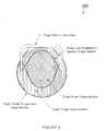
- FIG. 6illustrates a cross-sectional view of a thigh suspension mechanism according to an exemplary embodiment of the invention.
- Embodiments described hereininclude a relatively inexpensive orthotic system for functional rehabilitation of patients who have suffered loss of function due to illness or injury.
- the orthotic systemis designed to conform closely to the unique shape of an individual subject's leg without requiring the expense of a custom fit, while being provided in the fewest possible sizes that accommodate the widest range of subjects.
- the orthotic system described hereinlimits the points of structural contact of the primary orthotic structure to at most two (2) contacts: one on the proximal thigh and the other on the distal shin. This arrangement accommodates the shapes and sizes of a wide variety subject's appendages which occur between the two (2) contact points.
- Embodimentsare capable of attachment directly to the leg to provide not only support, but active mobility assistance in addition to continuous passive motion and robotic therapy.
- Embodimentsalso accommodate a center-mounted linear actuator and bell crank linkage coupled to the lower leg orthotic structure. Center mounting of the actuator along with the adjustability of the orthotic system allow the same device to fit either the right or left leg.
- a unified designeliminates the costs associated with the development, manufacturing and inventory, of different devices for each leg.
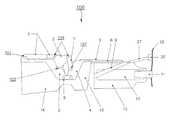
- FIG. 1illustrates a side-view diagram of an orthotic system according to an exemplary embodiment of the invention.
- orthotic system 100includes: linear actuator 1 ; bell crank 2 ; thigh orthotic structure 3 ; lower leg orthotic structure 4 ; tibia anterior structure 5 ; tibia posterior structure 6 ; connector link 7 ; hinge 8 ; tibia suspension system 9 ; lateral support structures 10 ; ankle suspension structure 11 ; footpad sensor system 12 ; lower leg textiles 13 ; thigh textile 14 ; upper shin textile 15 ; toe strap 26 ; and anti-foot drop system 27 .
- thisis given by way of example and not limitation, as the orthotic system described herein may include fewer or more components.
- Linear actuator 1acts directly on a linkage point of a bell crank rocker arm 2 .
- the linear actuator 1is mounted on a pivot 101 at the upper most end of the thigh orthotic structure 3 ; however, other embodiments would include the linear actuator 1 being constrained on a fixed plane or fixed via pivot on any portion of the thigh orthotic structure 3 or lower leg orthotic structure 4 or other structural parts. Alternate embodiments would also include indirect actuation via an input link between the linear actuator 1 and the bell crank 2 .
- the bell crank 2has one or more fixed pivots 103 on the same structure as the linear actuator 1 is mounted.
- the bell crank 2has dual fixed pivots 103 , both in a coaxial configuration with respect to one another on opposite lateral sides of the orthotic system 100 .
- the linear actuator 1operates on a point at or near the midline of both the orthotic system 100 and the bell crank 2 to split the forces into two (2) nearly equal components to balance torque transferred to the lower structure.
- the bell crank 2has two (2) output pivots 105 in the same lateral plane as the bell crank pivots 103 ; however, an alternate embodiment could have fewer or more output pivots 105 which are not necessarily aligned with the bell crank pivots 103 .
- At least certain embodimentsutilize two (2) link structures 7 which transfer forces to and from the lower orthotic structure 4 .
- the thigh orthotic structure 3is connected to the lower leg orthotic structure 4 using one or more hinge joints 8 .
- the hinge joints 8are located on each lateral side of the orthotic system 100 such that they can be placed in a coaxial configuration relative to the joint of the subject wearing the orthotic system 100 .
- the orthotic system 100uses a geared polycentric hinge joint 8 ; however, alternate embodiments may include the use of single pivot joints as well as other linkage systems (such as a crossed four-bar linkage or other similar multi-axis joints).
- the link structures 7act on individual pivots 107 on the lower leg structure 4 ; however, other embodiments include fewer or more pivots 107 or spherical joints.
- the distal portion of the tibia posterior structure 6is affixed to the tibia suspension system 9 such that high levels of force may be transmitted to the top of the lateral support structures 10 positioned on each of the lateral sides of the lower leg of the subject.
- the lateral support structures 10transmit forces vertically to the ankle suspension structure 11 and ultimately to the ground via the foot pad sensor system 12 .
- the lateral support structuresare attached to the lower leg textiles 13 which hold each of the lower leg components relative to one another and provide wide area support to the subject's body as well as padding between hard structures and the body.
- the thigh textile 14is attached to the thigh orthotic structure 3 at two (2) points at the proximal end of the structure as well as two (2) points laterally near each of the hinges 8 .
- Alternate embodimentsinclude the thigh textile 14 to be attached at one or more points at the distal end of the thigh orthotic structure 3 as well as one or more points at the proximal end of the thigh orthotic structure 3 .
- the upper shin textile 15is affixed to the lower leg orthotic structure 4 at two (2) lateral points near each hinge. Other embodiments include affixing the upper shin textile 15 in fewer or more places.
- the tibia suspension system 9is embodied as an adjustable webbing strap which connects the distal end of the tibia posterior structure 6 and the proximal end of the lateral support structures 10 .
- Alternate embodimentsmay include a combination of vertical force carrying tension structures which transfer force from any point on the tibia length system or similar anterior structure to any point on lateral structures similar to the lateral support structures 10 .
- the foot pad sensor system 12may be embodied by four (4) pressure sensitive sensors encased in textile. In at least certain embodiments, two sensors are located in the forefoot area and two are located under the heel of the subject. The design is such that the foot pad sensor can be reversed to accommodate both left and right feet.
- An optional toe strap 26is similarly reversible left to right and allows the footpad to be secured to the foot to eliminate a tripping hazard as well as giving a point of attachment for anti-foot drop system 27 .
- the illustrated embodimentincludes a passive foot drop tension system 27 which may be embodied as elastic webbing connecting the forefoot loop with the lower portion of the tibia posterior structure 6 .
- a passive foot drop tension system 27may be embodied as elastic webbing connecting the forefoot loop with the lower portion of the tibia posterior structure 6 .
- Alternate embodimentsmay include active foot drop devices including linear and rotational actuators placed inline between the toe strap 26 and the distal portion of the tibia posterior structure 6 or which could be hydraulic, pneumatic, electric, or remotely actuated via cable.
- Alternate embodiments of the foot pad sensor system 12include any number of sensors placed throughout the footpad.
- Additional embodiments of the pressure sensors in the orthotic designinclude placement of pressure sensors in anterior and posterior portions of the textiles as well as directly on the posterior side of the orthotic system facing the subject to facilitate determining the level of pressure and forces of exerted in and around these interfaces, and to automatically instruct or warn the subject of potential problems as well as facilitate using, for example, the pressure and force information as predictive feedback to software of the linear actuator for gait analysis.
- FIG. 2shows a configuration of the tibia alignment and length adjustment system according to an exemplary embodiment of the invention.
- the tibia alignment and length adjustment systemis integrated into the lower leg orthotic structure 4 , the tibia anterior structure 5 and the tibia posterior structure 6 .
- the tibia anterior structure 5can be rotated about a point 209 on the midline of the device's lower leg orthotic structure 4 .
- a structure with two (2) slots 211which have constant radii about the center point allow two (2) bolts to pass through and allow the lower leg orthotic structure 4 to be coupled with the tibia anterior structure 5 .
- This systemallows the structures 4 and 5 attached to the tibia anterior structure 6 to rotate relative the thigh orthotic structure 3 and the lower leg orthotic structure 4 .
- Alternate embodimentsinclude a single radius slot rotating about a fixed point, multi-position bolt or circular structures.
- the tibia length systemincludes three (3) slots oriented along the proximal/distal axis, two (2) slots 213 in the distal portion of the tibia anterior structure 5 and one (1) slot 215 in the proximal end of the tibia posterior structure 6 .
- the tibia posterior structure 6is allowed to move distally or proximally to adjust the length of the tibia posterior structure 6 relative to the proximal structures.
- Orthotic system 100allows the tibia structures 5 attached to the tibia anterior structure 6 to rotate relative the thigh orthotic structure 3 and the lower leg orthotic structure 4 to accommodate subjects with non-linear leg structure alignment such as those depicted in FIG. 3 , which illustrates examples of an orthotic system superimposed on subjects with varying degrees of leg alignment including nominal leg alignment as well as an extreme bowlegged subject and a knock-kneed subject.
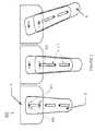
- FIG. 4illustrates a configuration of a thigh and knee textile tensioning system according to an exemplary embodiment of the invention.
- One embodimentutilizes zipper closure 16 for the upper textile portions of the system; however, alternate embodiments could implement hook and loop, button, snap, or other similar fasteners to close and tighten the textile system.
- Independent cable reel tensioning systems 18 and 19are implemented in the thigh textile system 14 to adjust tension across a broad surface area of the skin and soundly secure the orthotic system 100 to the subject.
- the cable reel tensioning systemimplements two (2) independent cable reels into the thigh textile system 14 ; however, alternate embodiments of the design can implement fewer or more cable reels (or fabric/webbing roller furling systems) to take up slack in the thigh textile 14 to affect textile tension and the fit of the orthotic to the subject. Additional embodiments of the tensioning system may include integration of pneumatic cells into the textile which can be statically inflated to a particular level to adjust fit to the subject or can be inflated dynamically through an inflation system (or via orthotic motion to dynamically massage the subject's appendage to assist in blood circulation through the appendage).
- the illustrated embodiment of FIG. 4includes a knee-lock tensioning system comprised of a cable reel system with loops of cable 21 / 22 exiting and entering the independent cable reel 19 .
- the cable loopis routed such that one direction of the cable loop is routed along the anterior portion of both the proximal and distal sections of the subject's knee creating the anterior knee lock cable loop 21 .
- the other direction of the same cableis routed along the posterior of the proximal and distal portions of the subject's knee while avoiding the area directly behind the knee to create the posterior knee lock cable loop 22 .
- the cableis isolated by an isolating nut 23 such that the lengths of the anterior and posterior loops 21 / 22 of the knee lock system are maintained without affecting one another.
- the isolation nut 23can be loosened to adjust the relative amount of cable in each of the posterior and anterior loops of cable. Alternate embodiments could implement webbing furling or webbing ratcheting systems to affect the same locking phenomenon.
- the knee lock systemwhen adjusted properly locates the subject's knee joint axis in a coaxial configuration with the hinge joints 8 of the orthotic system 100 .
- the illustrated embodiment of FIG. 4also includes a proximal thigh tensioning system.
- the independent proximal thigh cable reel 18may be designed to induce tension and a solid, stable interface between the subject's proximal thigh and the thigh orthotic structure at the proximal end of the structure, off of which leverage may be gained when applying torque to the subject's leg.
- the proximal thigh tension cable 24forms two (2) loops which cover a broad area and distribute force evenly throughout the textile.
- the orthotic structurehas clearance near the knee and does not require structural elements in close proximity to the kneecap. This design prevents the orthotic from applying unwanted forces to the knee. The clearance allows for post-surgical bandages and allows icepacks to be applied and removed while the orthotic remains in place.
- FIG. 5illustrates a configuration of a lower shin textile tensioning system according to an exemplary embodiment of the invention.
- the illustrated embodimentutilizes zipper closure 17 for the lower textile portions of the system; however, alternate embodiments could implement hook and loop, button, snap, or other similar fasteners to close and tighten the textile system.
- Independent cable reel tensioning system 20is implemented in the lower leg textile system 13 to adjust the level of tension across a broad surface area of the subject's lower leg and soundly secure the orthotic system 100 to the subject.
- the cableis routed in a single lower shin tensioning loop 25 originating and terminating at the reel 20 and routed around the leg such that it can affect the slack between the lateral support structures 10 and the tibia posterior structure 6 as well as the portion of textile around the posterior of the subject's calf.
- Alternate embodiments of the designcould implement a similar cable, textile, or webbing ratcheting furling or reel system.
- FIG. 6illustrates a cross-sectional view of the thigh textile suspension mechanism according to an exemplary embodiment.
- the thigh textile suspension(and similar tibia suspension system 9 ) keeps the thigh orthotic structure from coming into direct contact with the subject's thigh.
- the forcemay be communicated through the thigh textiles.
- This arrangementis of particular advantage for active orthotic systems in which force is applied by an actuator to aide in leg extension for sit-to-stand mobility and ascending stairs, and to apply force to resist gravity to aide in stand-to-sit mobility and descending stairs.
- the textile-based suspensionis more advantageous than the padding of traditional braces because active orthotics require movement of the brace to be communicated directly into movement of the leg.
- brace movement and leg movement to be closely coupledIf there is too much padding, movement of the brace may only compress the padding and not effectively communicate the force to the subject's leg.
- Use of a non-stretch fabric for the textileallows force to be communicated to a large area of the subject's leg comfortably, yet the fabric itself does not stretch allowing brace movement and leg movement to be closely coupled.
- Embodimentsare not limited to the techniques and materials discussed herein.
- the structural elementscould be constructed of carbon fiber, fiberglass, aluminum, steel or another rigid material.
- the textile portioncould be comprised of any compliant material including fabric, webbing or flexible plastics.
- An embodimenthas been described for the knee, but braces with the same the multi-fit and mobility-assistance features could be applied to other joints such as the ankle, elbow, hip and shoulder.
- references to “one embodiment,” “an embodiment,” “an example embodiment,”indicate that the embodiment described may include a particular feature, structure, or characteristic; however every embodiment may not necessarily include the particular feature, structure, or characteristic. Moreover, such phrases are not necessarily referring to the same embodiment.
- a particular feature, structure, or characteristicis described in connection with an embodiment, it is submitted that it is within the knowledge of one skilled in the art to bring about such a feature, structure, or characteristic in connection with other embodiments, whether or not explicitly described.
- Various changesmay be made in the structure and embodiments shown herein without departing from the principles of this description.
- Coupledis used to indicate that two (2) or more elements are in direct physical or electrical contact with each other.
- Connectedis used to indicate that two (2) or more elements are in direct physical or electrical contact with each other.
- Coupledmay mean that two (2) or more elements are in direct physical or electrical contact.
- coupledmay also mean that two (2) or more elements are not in direct contact with each other, but yet still cooperate or interact with each other.
- Embodiments of the inventionmay include various operations as set forth above or fewer operations or more operations, or operations in an order which is different from the order described herein.
- numerous specific detailswere set forth in order to provide a thorough understanding of the invention. It will be apparent, however, to one skilled in the art that the invention may be practiced without some of these specific details. Accordingly, the scope and spirit of the invention should be judged in terms of the claims which follow as well as the legal equivalents thereof.
Landscapes
- Health & Medical Sciences (AREA)
- Nursing (AREA)
- Orthopedic Medicine & Surgery (AREA)
- Engineering & Computer Science (AREA)
- Biomedical Technology (AREA)
- Heart & Thoracic Surgery (AREA)
- Vascular Medicine (AREA)
- Life Sciences & Earth Sciences (AREA)
- Animal Behavior & Ethology (AREA)
- General Health & Medical Sciences (AREA)
- Public Health (AREA)
- Veterinary Medicine (AREA)
- Orthopedics, Nursing, And Contraception (AREA)
- Rehabilitation Tools (AREA)
Abstract
Description
Claims (3)
Priority Applications (3)
| Application Number | Priority Date | Filing Date | Title |
|---|---|---|---|
| US12/366,998US8052629B2 (en) | 2008-02-08 | 2009-02-06 | Multi-fit orthotic and mobility assistance apparatus |
| US13/274,109US8771210B2 (en) | 2008-02-08 | 2011-10-14 | Multi-fit orthotic and mobility assistance apparatus |
| US14/325,935US20140323936A1 (en) | 2008-02-08 | 2014-07-08 | Multi-fit orthotic and mobility assistance apparatus |
Applications Claiming Priority (2)
| Application Number | Priority Date | Filing Date | Title |
|---|---|---|---|
| US2736508P | 2008-02-08 | 2008-02-08 | |
| US12/366,998US8052629B2 (en) | 2008-02-08 | 2009-02-06 | Multi-fit orthotic and mobility assistance apparatus |
Related Child Applications (1)
| Application Number | Title | Priority Date | Filing Date |
|---|---|---|---|
| US13/274,109ContinuationUS8771210B2 (en) | 2008-02-08 | 2011-10-14 | Multi-fit orthotic and mobility assistance apparatus |
Publications (2)
| Publication Number | Publication Date |
|---|---|
| US20090204038A1 US20090204038A1 (en) | 2009-08-13 |
| US8052629B2true US8052629B2 (en) | 2011-11-08 |
Family
ID=40939507
Family Applications (3)
| Application Number | Title | Priority Date | Filing Date |
|---|---|---|---|
| US12/366,998Active2029-12-20US8052629B2 (en) | 2008-02-08 | 2009-02-06 | Multi-fit orthotic and mobility assistance apparatus |
| US13/274,109ActiveUS8771210B2 (en) | 2008-02-08 | 2011-10-14 | Multi-fit orthotic and mobility assistance apparatus |
| US14/325,935AbandonedUS20140323936A1 (en) | 2008-02-08 | 2014-07-08 | Multi-fit orthotic and mobility assistance apparatus |
Family Applications After (2)
| Application Number | Title | Priority Date | Filing Date |
|---|---|---|---|
| US13/274,109ActiveUS8771210B2 (en) | 2008-02-08 | 2011-10-14 | Multi-fit orthotic and mobility assistance apparatus |
| US14/325,935AbandonedUS20140323936A1 (en) | 2008-02-08 | 2014-07-08 | Multi-fit orthotic and mobility assistance apparatus |
Country Status (2)
| Country | Link |
|---|---|
| US (3) | US8052629B2 (en) |
| WO (1) | WO2009099671A2 (en) |
Cited By (11)
| Publication number | Priority date | Publication date | Assignee | Title |
|---|---|---|---|---|
| US8771210B2 (en) | 2008-02-08 | 2014-07-08 | Alterg, Inc. | Multi-fit orthotic and mobility assistance apparatus |
| WO2014159857A3 (en)* | 2013-03-14 | 2014-11-27 | Ekso Bionics, Inc. | Powered orthotic system for cooperative overground rehabilitation |
| US9131873B2 (en) | 2009-02-09 | 2015-09-15 | Alterg, Inc. | Foot pad device and method of obtaining weight data |
| US9285020B2 (en) | 2013-02-28 | 2016-03-15 | Adicep Technologies, Inc | Open belt clutch |
| US9295302B1 (en) | 2012-02-17 | 2016-03-29 | University Of South Florida | Gait-altering shoes |
| US9474673B2 (en) | 2007-02-14 | 2016-10-25 | Alterg, Inc. | Methods and devices for deep vein thrombosis prevention |
| US9889058B2 (en) | 2013-03-15 | 2018-02-13 | Alterg, Inc. | Orthotic device drive system and method |
| US10179078B2 (en) | 2008-06-05 | 2019-01-15 | Alterg, Inc. | Therapeutic method and device for rehabilitation |
| US10485721B2 (en) | 2014-11-27 | 2019-11-26 | AOD Holdings, LLC | Surgical leg positioner |
| US10751241B2 (en) | 2014-11-27 | 2020-08-25 | AOD Holdings, LLC | Surgical leg positioner |
| US11883159B2 (en) | 2017-05-05 | 2024-01-30 | DePuy Synthes Products, Inc. | Patient range of motion monitor |
Families Citing this family (18)
| Publication number | Priority date | Publication date | Assignee | Title |
|---|---|---|---|---|
| US8425579B1 (en)* | 2002-10-08 | 2013-04-23 | Vitalwear, Inc. | Therapeutic knee brace for a contrast therapy system |
| US6966882B2 (en)* | 2002-11-25 | 2005-11-22 | Tibion Corporation | Active muscle assistance device and method |
| US7811189B2 (en)* | 2005-12-30 | 2010-10-12 | Tibion Corporation | Deflector assembly |
| US8274244B2 (en) | 2008-08-14 | 2012-09-25 | Tibion Corporation | Actuator system and method for extending a joint |
| US8058823B2 (en) | 2008-08-14 | 2011-11-15 | Tibion Corporation | Actuator system with a multi-motor assembly for extending and flexing a joint |
| US10278885B1 (en) | 2011-07-29 | 2019-05-07 | Leonis Medical Corporation | Method and system for control and operation of motorized orthotic exoskeleton joints |
| US9545353B2 (en) | 2011-07-29 | 2017-01-17 | Leonis Medical Corporation | Methods of operating an exoskeleton for gait assistance and rehabilitation |
| US11400010B2 (en) | 2011-07-29 | 2022-08-02 | Leonis Medical Corporation | Method and system for control and operation of motorized orthotic exoskeleton joints |
| WO2015017462A1 (en)* | 2013-07-30 | 2015-02-05 | United Surgical Associates, Inc. | Orthopedic brace securing and tensioning system |
| WO2015138317A1 (en) | 2014-03-10 | 2015-09-17 | Stryker Corporation | Limb positioning system |
| US10182957B2 (en) | 2014-06-18 | 2019-01-22 | Ossur Hf | Continuous passive motion device |
| US9951904B2 (en) | 2015-03-24 | 2018-04-24 | Stryker Corporation | Rotatable seat clamps for rail clamp |
| US9892837B2 (en) | 2015-05-21 | 2018-02-13 | Adicep Technologies, Inc | Energy efficient actuator |
| US10075046B2 (en)* | 2015-10-14 | 2018-09-11 | Bionic Power Inc. | Steady ratio four-bar linkage for genuflective energy harvesting |
| EP3173053B1 (en) | 2015-11-26 | 2025-04-09 | Samsung Electronics Co., Ltd. | Motion assistance apparatus including a frame assembly |
| CN110859708B (en)* | 2018-08-28 | 2021-12-10 | 奉节县中医院 | Automatic robot for making bandage |
| CN109157286B (en)* | 2018-10-25 | 2020-12-08 | 北京爱康宜诚医疗器材有限公司 | Data prediction method and device |
| CN110215326A (en)* | 2019-05-30 | 2019-09-10 | 河北医科大学第三医院 | It is a kind of for correcting the device of valgus deformity in ankle-joint |
Citations (192)
| Publication number | Priority date | Publication date | Assignee | Title |
|---|---|---|---|---|
| US1286482A (en) | 1917-08-25 | 1918-12-03 | Isidor A Schulherr | Belt-tightener. |
| US1366904A (en) | 1921-02-01 | X t tightening | ||
| US1391290A (en) | 1918-10-03 | 1921-09-20 | Welffens Emile John | Transmission mechanism |
| US1513473A (en) | 1923-06-04 | 1924-10-28 | Curtis & Company Mfg Company | Automatic belt tightener |
| US1739053A (en) | 1927-07-08 | 1929-12-10 | Verne E Minich | Worm-drive belt-tightening device |
| US1847720A (en) | 1928-09-10 | 1932-03-01 | Marcellis Carmen Wood | Spring belt tension adjuster |
| US2169813A (en) | 1937-03-13 | 1939-08-15 | Exactor Control Company Ltd | Mechanical remote control apparatus |
| US3059490A (en) | 1961-01-11 | 1962-10-23 | Sperry Rand Corp | Control device |
| US3200666A (en) | 1960-08-04 | 1965-08-17 | Reimers Getriebe Kg | Control mechanism for a driving unit consisting of a driving engine and an infinitely variable gear |
| US3358678A (en) | 1964-07-29 | 1967-12-19 | Kultsar Emery | Moving and support system for the human body |
| US3398248A (en) | 1967-07-07 | 1968-08-20 | Eastman Kodak Co | Cam actuator |
| US3402942A (en) | 1966-06-17 | 1968-09-24 | Shimano Industrial Co | Device for tensioning the driving chain in a bicycle equipped with coaster brake and exposed speed change gear |
| US3631542A (en) | 1969-08-11 | 1972-01-04 | Univ Iowa State Res Found | Myoelectric brace |
| US3641843A (en) | 1969-09-22 | 1972-02-15 | Joseph Lemmens | Variable-speed transmission |
| US3863512A (en) | 1973-11-09 | 1975-02-04 | California Progressive Prod | Shift mechanism for derailleur drive |
| US3899383A (en) | 1974-03-15 | 1975-08-12 | Minnesota Mining & Mfg | Strip applying device |
| US3925131A (en) | 1971-05-14 | 1975-12-09 | Hauni Werke Koerber & Co Kg | Method of uniting webs of cigarette paper or the like |
| US3976057A (en)* | 1974-12-23 | 1976-08-24 | Clarence F. Bates | Joint flexing apparatus |
| US4507104A (en) | 1983-05-31 | 1985-03-26 | Pitney Bowes Inc. | Eccentric pulley for inelastic timing belt |
| US4549555A (en) | 1984-02-17 | 1985-10-29 | Orthothronics Limited Partnership | Knee laxity evaluator and motion module/digitizer arrangement |
| US4588040A (en) | 1983-12-22 | 1986-05-13 | Albright Jr Harold D | Hybrid power system for driving a motor vehicle |
| US4649488A (en) | 1983-06-06 | 1987-03-10 | Toyota Jidosha Kabushiki Kaisha | Method and apparatus for controlling continuously variable transmission for vehicle |
| US4678354A (en) | 1985-12-02 | 1987-07-07 | Xerox Corporation | Typewriter cable tensioning mechanism |
| US4691694A (en) | 1984-11-29 | 1987-09-08 | Biodex Corporation | Muscle exercise and rehabilitation apparatus |
| US4697808A (en) | 1985-05-16 | 1987-10-06 | Wright State University | Walking assistance system |
| US4731044A (en) | 1985-12-18 | 1988-03-15 | Borg-Warner Automotive, Inc. | Tension sensor and control arrangement for a continuously variable transmission |
| US4745930A (en) | 1986-10-16 | 1988-05-24 | Chattanooga Corporation | Force sensing insole for electro-goniometer |
| US4754185A (en) | 1986-10-16 | 1988-06-28 | American Telephone And Telegraph Company, At&T Bell Laboratories | Micro-electrostatic motor |
| US4796631A (en) | 1987-06-11 | 1989-01-10 | Grigoryev Leon M | Electrical muscle stimulator for knee stabilization |
| US4807874A (en) | 1987-07-24 | 1989-02-28 | Little Lloyd R | Combination plantar flexion/dorsiflexion ankle machine |
| US4872665A (en) | 1985-10-30 | 1989-10-10 | Chareire Jean Louis | Mechanical leg-propulsion assistance device |
| US4878663A (en) | 1988-11-08 | 1989-11-07 | Innovative Therapeutic Designs, Inc. | Direct drive rehabilitation and fitness apparatus and method of construction |
| US4883445A (en) | 1987-10-16 | 1989-11-28 | Mannesmann Aktiengesellschaft | Device for tensioning of a pulling element of a printer |
| US4922925A (en) | 1988-02-29 | 1990-05-08 | Washington University | Computer based upper extremity evaluation system |
| US4934694A (en) | 1985-12-06 | 1990-06-19 | Mcintosh James L | Computer controlled exercise system |
| US4944713A (en) | 1989-10-30 | 1990-07-31 | Mark Salerno | Treadmill speed reset system |
| US4953543A (en) | 1988-08-09 | 1990-09-04 | Royce Medical Company | Cruciate ligament leg brace |
| WO1990011049A1 (en) | 1989-03-23 | 1990-10-04 | David Fitness & Medical Ltd Oy | Method for measuring muscular functionality and measuring and training system for muscular functionality measurements and muscle training |
| US4981116A (en) | 1988-12-16 | 1991-01-01 | Caoutchouc Manufacture Et Plastiques S.A. | Apparatus and method for wrapping a belt in an internal combustion engine and the like and an internal combustion engine with apparatus for wrapping a belt and associated method |
| US4983146A (en) | 1987-03-23 | 1991-01-08 | Colorocs Corporation | Belt tensioning and quick release device for electrophotographic system |
| US5020790A (en) | 1990-10-23 | 1991-06-04 | Board Of Supervisors Of Louisiana State University And Agricultural And Mechanical College | Powered gait orthosis |
| US5052681A (en) | 1989-12-11 | 1991-10-01 | Williams George R | Upper extremity rehabilitation device |
| US5078152A (en) | 1985-06-23 | 1992-01-07 | Loredan Biomedical, Inc. | Method for diagnosis and/or training of proprioceptor feedback capabilities in a muscle and joint system of a human patient |
| US5117814A (en) | 1990-03-16 | 1992-06-02 | Q-Motus, Inc. | Dynamic splint |
| US5170777A (en) | 1990-12-28 | 1992-12-15 | The University Of Akron | Arm rehabilitation and testing device |
| US5195617A (en) | 1991-11-12 | 1993-03-23 | General Motors Corporation | Brake linkage self-adjustment mechanism |
| US5203321A (en) | 1990-12-11 | 1993-04-20 | Sutter Corporation | Passive anatomic ankle-foot exerciser |
| US5209223A (en) | 1991-03-20 | 1993-05-11 | Biodex Medical Systems, Inc. | Single chair muscle exercise and rehabilitation apparatus |
| US5213094A (en) | 1990-07-30 | 1993-05-25 | Bonutti Peter M | Orthosis with joint distraction |
| US5239222A (en) | 1989-04-24 | 1993-08-24 | Fujitsu Limited | Electrostatic actuator using films |
| US5241952A (en) | 1992-03-30 | 1993-09-07 | Ortiz David G | Therapeutic range-of-motion exercise device |
| US5282460A (en) | 1992-01-06 | 1994-02-01 | Joyce Ann Boldt | Three axis mechanical joint for a power assist device |
| US5303716A (en) | 1992-11-12 | 1994-04-19 | Breg, Inc. | Portable device for rehabilitative exercise of the leg |
| US5313968A (en) | 1990-04-23 | 1994-05-24 | Washington University | Joint range of motion analyzer using euler angle |
| US5345834A (en) | 1991-01-08 | 1994-09-13 | Kabushiki Kaisha Sankyo Seiki Seisakusho | Velocity-reduced drive system |
| US5358468A (en) | 1993-03-26 | 1994-10-25 | Matthew C. Longo | Adjustable resistance knee rehabilitating and strengthening apparatus |
| US5378954A (en) | 1990-04-16 | 1995-01-03 | Fujitsu Limited | Electrostatic actuator |
| US5421798A (en) | 1993-05-17 | 1995-06-06 | Cedaron Medical, Inc. | Closed chain evaluation and exercise system |
| US5440945A (en) | 1993-04-19 | 1995-08-15 | Penn; Jay P. | Hardgeared infinitely variable transmission |
| US5448124A (en) | 1992-08-25 | 1995-09-05 | Kanagawa Academy Of Science And Technology | Electrostatic actuator |
| US5463526A (en) | 1994-01-21 | 1995-10-31 | Lam Research Corporation | Hybrid electrostatic chuck |
| US5476441A (en) | 1993-09-30 | 1995-12-19 | Massachusetts Institute Of Technology | Controlled-brake orthosis |
| US5520627A (en) | 1993-06-30 | 1996-05-28 | Empi, Inc. | Range-of-motion ankle splint |
| US5525642A (en) | 1991-05-30 | 1996-06-11 | The Dow Chemical Company | Electroresponsive polymer systems |
| US5534740A (en) | 1991-05-27 | 1996-07-09 | Fujitsu Limited | Electrostatic actuator and method of controlling the same |
| US5582579A (en) | 1994-12-01 | 1996-12-10 | Chism; Jeffrey K. | Orthopedic therapy and rehabilitation device |
| US5624390A (en) | 1994-12-14 | 1997-04-29 | Van Dyne; Leonard A. | Prosthetic joint with dynamic torque compensator |
| US5653680A (en) | 1995-08-10 | 1997-08-05 | Cruz; Mark K. | Active wrist brace |
| US5662594A (en) | 1995-06-09 | 1997-09-02 | Rosenblatt; Marc | Dynamic exoskeletal orthosis |
| US5662693A (en) | 1995-06-05 | 1997-09-02 | The United States Of America As Represented By The Secretary Of The Air Force | Mobility assist for the paralyzed, amputeed and spastic person |
| US5674262A (en) | 1996-01-26 | 1997-10-07 | Kinetic Concepts, Inc. | Pneumatic compression and functional electric stimulation device and method using the same |
| US5683351A (en) | 1994-09-27 | 1997-11-04 | Jace Systems, Inc. | Continuous passive motion device for a hand |
| US5704440A (en) | 1995-05-31 | 1998-01-06 | New York Institute Of Technology | Energy distribution method for hydrid electric vehicle |
| US5708319A (en) | 1995-03-23 | 1998-01-13 | Kabushiki Kaisha Toyoda Jidoshokki Seisakusho | Multiple axes drive apparatus with electrostatic drive means |
| US5728017A (en) | 1990-05-08 | 1998-03-17 | E.B.T., Inc. | Electronic transmission control system for a bicycle or the like |
| US5746704A (en) | 1995-08-04 | 1998-05-05 | Schenck; Robert R. | Therapy apparatus having a passive motion device for flexing a body member |
| US5746684A (en) | 1996-12-05 | 1998-05-05 | Jordan; James L. | Foundation stand and method of use |
| US5755303A (en) | 1996-04-02 | 1998-05-26 | Honda Giken Kogyo Kabushiki Kaisha | Power transmitting apparatus for a hybrid vehicle |
| US5789843A (en) | 1994-03-18 | 1998-08-04 | Kanagawa Academy Of Science And Technology | Electrostatically levitated conveyance apparatus and electrode thereof for electrostatic levitation |
| US5833257A (en) | 1994-03-17 | 1998-11-10 | Kohlheb; Robert | Alternating drive for wheeled vehicles |
| US5865770A (en) | 1995-12-06 | 1999-02-02 | Schectman; Leonard A. | Device to counteract paralysis |
| US5916689A (en) | 1995-01-12 | 1999-06-29 | Applied Materials, Inc. | Electrostatic chuck with an impregnated, porous layer that exhibits the Johnson-Rahbeck effect |
| US5931756A (en) | 1997-08-04 | 1999-08-03 | Honda Giken Kogyo Kabushiki Kaisha | Metal V-belt type continuously variable transmission |
| US5976063A (en) | 1993-07-09 | 1999-11-02 | Kinetecs, Inc. | Exercise apparatus and technique |
| US6001075A (en) | 1997-12-12 | 1999-12-14 | Ex. P.H. | Dynamic splint |
| US6033330A (en) | 1991-06-27 | 2000-03-07 | Xerox Corporation | Belt noise/vibration control mechanism |
| US6062096A (en) | 1998-06-02 | 2000-05-16 | Lester; William T. | Continuously variable transmission utilizing oscillating torque and one way drives |
| US6119539A (en) | 1998-02-06 | 2000-09-19 | Galaxy Shipping Enterprises, Inc. | Infinitely and continuously variable transmission system |
| US6149612A (en) | 1998-09-14 | 2000-11-21 | Schnapp; Moacir | Rehabilitative apparatus for treating reflex sympathetic dystrophy |
| US6162189A (en) | 1999-05-26 | 2000-12-19 | Rutgers, The State University Of New Jersey | Ankle rehabilitation system |
| US6183431B1 (en) | 1998-08-31 | 2001-02-06 | Richard E. Gach, Jr. | Metatarsal fracture neutralizer |
| US6217532B1 (en) | 1999-11-09 | 2001-04-17 | Chattanooga Group, Inc. | Continuous passive motion device having a progressive range of motion |
| US6221032B1 (en) | 1999-11-09 | 2001-04-24 | Chattanooga Group, Inc. | Continuous passive motion device having a rehabilitation enhancing mode of operation |
| US6290662B1 (en) | 1999-05-28 | 2001-09-18 | John K. Morris | Portable, self-contained apparatus for deep vein thrombosis (DVT) prophylaxis |
| EP1138286A2 (en) | 2000-03-28 | 2001-10-04 | Seiko Epson Corporation | Wearable muscular-force supplementing device |
| US6314835B1 (en) | 1999-02-01 | 2001-11-13 | Harmonic Drive Technologies | Piezo-electric drive arrangement for a harmonic drive transmission |
| US6440093B1 (en) | 1996-04-29 | 2002-08-27 | Mcewen James Allen | Apparatus and method for monitoring pneumatic limb compression therapy |
| US6472795B2 (en) | 2000-03-01 | 2002-10-29 | Canon Kabushiki Kaisha | Electrostatic actuator and method of driving the same |
| US6494798B1 (en) | 1999-11-13 | 2002-12-17 | Tokyo Automatic Machinery Co., Ltd. | Pulley press controlling apparatus using an elastic member for belt transmission |
| US6500138B1 (en) | 2000-04-07 | 2002-12-31 | Mayo Foundation For Medical Education And Research | Electromechanical joint control device with wrap spring clutch |
| US6517503B1 (en) | 1998-09-18 | 2003-02-11 | Becker Orthopedic Appliance Company | Orthosis knee joint |
| US6525446B1 (en) | 1999-06-14 | 2003-02-25 | Canon Kabushiki Kaisha | Electrostatic actuator driving method and mechanism, using rigidity retention as a parameter |
| US6527671B2 (en) | 2000-06-21 | 2003-03-04 | Prorauta | Planetary gear transmission with variable ratio |
| US6533742B1 (en) | 1998-08-31 | 2003-03-18 | Richard E. Gach, Jr. | Metatarsal fracture neutralizer |
| US6537175B1 (en) | 2000-10-10 | 2003-03-25 | Michael W. Blood | Power system |
| US6554773B1 (en) | 1997-09-12 | 2003-04-29 | Polar Electro Oy | Method and arrangement for blood pressure measurement |
| US6572558B2 (en) | 2000-05-13 | 2003-06-03 | Omegawave, Llc | Apparatus and method for non-invasive measurement of current functional state and adaptive response in humans |
| US20030104886A1 (en) | 2001-11-27 | 2003-06-05 | Witold Gajewski | Synchronous drive apparatus and methods |
| US20030120183A1 (en) | 2000-09-20 | 2003-06-26 | Simmons John C. | Assistive clothing |
| US6599255B2 (en) | 2001-05-31 | 2003-07-29 | Rehabilitation Institute Of Chicago | Portable intelligent stretching device |
| US20030195638A1 (en) | 2002-04-16 | 2003-10-16 | Isamu Kajitani | Artificial hand |
| US6659910B2 (en) | 2001-11-14 | 2003-12-09 | Industrial Technology Research Institute | Hybrid power system with continuously variable speed |
| US6666796B1 (en) | 1999-09-16 | 2003-12-23 | Aerovironment, Inc. | Walking assisting apparatus |
| US20040015112A1 (en) | 2002-02-14 | 2004-01-22 | Salutterback E. Gerald | Controlled motion ankle walker brace |
| US6689075B2 (en) | 2000-08-25 | 2004-02-10 | Healthsouth Corporation | Powered gait orthosis and method of utilizing same |
| US6694833B2 (en) | 2001-06-28 | 2004-02-24 | Drive-All Manufacturing Company, Inc. | Multi-speed worm gear reduction assembly |
| US20040049139A1 (en)* | 2002-09-05 | 2004-03-11 | Marin Craciunescu | Therapeutic lower extremity device |
| US20040054311A1 (en) | 2002-06-28 | 2004-03-18 | Shane Sterling | Anatomically designed orthopedic knee brace |
| US6709411B1 (en) | 1999-03-18 | 2004-03-23 | David R. Olinger | Shoulder brace, and methods of use |
| US20040078091A1 (en) | 2002-10-15 | 2004-04-22 | Elkins Jeffrey L. | Foot-operated controller |
| US20040106881A1 (en) | 2002-11-21 | 2004-06-03 | Mcbean John M. | Powered orthotic device |
| US6796926B2 (en) | 2001-08-22 | 2004-09-28 | The Regents Of The University Of California | Mechanism for manipulating and measuring legs during stepping |
| US6805677B2 (en) | 2000-09-20 | 2004-10-19 | John Castle Simmons | Wheel-less walking support and rehabilitation device |
| US6821262B1 (en) | 2001-08-31 | 2004-11-23 | Richard R. Muse | Self operable knee extension therapy device |
| US6827579B2 (en) | 2000-11-16 | 2004-12-07 | Rutgers, The State University Of Nj | Method and apparatus for rehabilitation of neuromotor disorders |
| US6836744B1 (en) | 2000-08-18 | 2004-12-28 | Fareid A. Asphahani | Portable system for analyzing human gait |
| US20050014600A1 (en) | 2003-07-14 | 2005-01-20 | Clauson Luke W. | Methods and devices for altering the transmission ratio of a drive system |
| US6872187B1 (en) | 1998-09-01 | 2005-03-29 | Izex Technologies, Inc. | Orthoses for joint rehabilitation |
| US6878122B2 (en) | 2002-01-29 | 2005-04-12 | Oregon Health & Science University | Method and device for rehabilitation of motor dysfunction |
| US20050085346A1 (en) | 2003-10-16 | 2005-04-21 | Johnson Kenneth W. | Rotary rehabilitation apparatus and method |
| US20050085353A1 (en) | 2003-10-16 | 2005-04-21 | Johnson Kenneth W. | Rotary rehabilitation apparatus and method |
| WO2005057054A1 (en) | 2003-12-09 | 2005-06-23 | Toyota Jidosha Kabushiki Kaisha | Belt type continuously variable transmission |
| US20050151420A1 (en) | 2001-05-07 | 2005-07-14 | Dale Crombez | Hybrid electric vehicle powertrain with regenerative braking |
| US20050173994A1 (en) | 2004-02-09 | 2005-08-11 | Societe Industrielle De Sonceboz Sa | Linear actuator |
| US6936994B1 (en) | 2002-09-03 | 2005-08-30 | Gideon Gimlan | Electrostatic energy generators and uses of same |
| US20050210557A1 (en) | 2004-03-25 | 2005-09-29 | Falconer Glen M | H.A.L.O. hybird |
| US20050221926A1 (en) | 2003-10-13 | 2005-10-06 | Varibox (Pty) Limited | Infinitely variable transmission |
| US6966882B2 (en) | 2002-11-25 | 2005-11-22 | Tibion Corporation | Active muscle assistance device and method |
| US20050273022A1 (en) | 2004-05-10 | 2005-12-08 | Robert Diaz | Portable therapy device |
| US20060004265A1 (en) | 2004-06-16 | 2006-01-05 | Firstbeat Technologies Oy. | System for monitoring and predicting physiological state under physical exercise |
| US20060069336A1 (en) | 2004-09-27 | 2006-03-30 | Massachusetts Institute Of Technology | Ankle interface |
| US7041069B2 (en) | 2002-07-23 | 2006-05-09 | Health South Corporation | Powered gait orthosis and method of utilizing same |
| US20060132069A1 (en) | 2003-08-16 | 2006-06-22 | Jeff Hemphill | Actuation device |
| US20060157010A1 (en) | 2004-12-28 | 2006-07-20 | Yuji Moriwaki | Hydraulic valve driving device and engine including the same and vehicle |
| US20060206045A1 (en) | 2005-03-08 | 2006-09-14 | Townsend Industries, Inc. | Post operative knee brace with multiple adjustment features |
| US7124321B2 (en) | 2003-02-10 | 2006-10-17 | Sun Microsystems, Inc. | Adaptive throttling |
| US20060249315A1 (en) | 2005-03-31 | 2006-11-09 | Massachusetts Institute Of Technology | Artificial human limbs and joints employing actuators, springs, and variable-damper elements |
| US20060251179A1 (en) | 2005-03-28 | 2006-11-09 | Akros Silicon, Inc. | Ethernet bridge |
| US7137938B2 (en) | 2002-07-10 | 2006-11-21 | Gottlieb Marc S | Exercise device and method of using the same |
| US20060293624A1 (en) | 1999-09-27 | 2006-12-28 | Robert-Jan Enzerink | Orthopaedic brace having a range of motion hinge with an adjustable-length strut |
| US20070015611A1 (en) | 2005-07-13 | 2007-01-18 | Ultimate Balance, Inc. | Orientation and motion sensing in athletic training systems, physical rehabilitation and evaluation systems, and hand-held devices |
| US7171331B2 (en) | 2001-12-17 | 2007-01-30 | Phatrat Technology, Llc | Shoes employing monitoring devices, and associated methods |
| WO2007027673A2 (en) | 2005-08-30 | 2007-03-08 | Cisco Technology, Inc. | Low-power ethernet device |
| US20070055163A1 (en) | 2005-08-22 | 2007-03-08 | Asada Haruhiko H | Wearable blood pressure sensor and method of calibration |
| US7190141B1 (en) | 2006-01-27 | 2007-03-13 | Villanova University | Exoskeletal device for rehabilitation |
| US7192401B2 (en) | 2002-08-16 | 2007-03-20 | Firstbeat Technologies Oy | Method for monitoring accumulated body fatigue for determining recovery during exercise or activity |
| WO2007041303A2 (en) | 2005-09-30 | 2007-04-12 | Djo, Llc | Knee brace having a rigid frame and patellofemoral support |
| US7239065B2 (en) | 2003-07-08 | 2007-07-03 | Tibion Corporation | Electrostatic actuator with fault tolerant electrode structure |
| US20070155558A1 (en) | 2005-12-30 | 2007-07-05 | Horst Robert W | Continuously variable transmission |
| US20070155560A1 (en) | 2005-12-30 | 2007-07-05 | Horst Robert W | Linear actuator |
| US20070155557A1 (en) | 2005-12-30 | 2007-07-05 | Horst Robert W | Deflector assembly |
| US20070162152A1 (en) | 2005-03-31 | 2007-07-12 | Massachusetts Institute Of Technology | Artificial joints using agonist-antagonist actuators |
| US7252644B2 (en) | 2004-09-29 | 2007-08-07 | Northwestern University | System and methods to overcome gravity-induced dysfunction in extremity paresis |
| US20070225620A1 (en) | 2006-03-23 | 2007-09-27 | Carignan Craig R | Portable Arm Exoskeleton for Shoulder Rehabilitation |
| US20070265534A1 (en) | 2006-05-12 | 2007-11-15 | Suunto Oy | Method, device and computer program product for monitoring the physiological state of a person |
| US20070270265A1 (en) | 2003-08-11 | 2007-11-22 | Fallbrook Technologies Inc. | Continuously variable planetary gear set |
| US20070287928A1 (en) | 2006-05-03 | 2007-12-13 | Polar Electro Oy | Method, user-specific performance monitor, system, and computer software product |
| US7324841B2 (en) | 2001-02-19 | 2008-01-29 | Polar Electro Oy | Sensor arrangeable on the skin |
| US20080039731A1 (en) | 2005-08-22 | 2008-02-14 | Massachusetts Institute Of Technology | Wearable Pulse Wave Velocity Blood Pressure Sensor and Methods of Calibration Thereof |
| US20080097269A1 (en) | 2004-11-09 | 2008-04-24 | Brian Weinberg | Electro-Rheological Fluid Brake and Actuator Devices and Orthotic Devices Using the Same |
| US7365463B2 (en) | 2005-01-10 | 2008-04-29 | Tibion Corporation | High-torque motor |
| US7410471B1 (en) | 1998-09-18 | 2008-08-12 | Becker Orthopedic Appliance Company | Orthosis knee joint and sensor |
| US20080195005A1 (en) | 2007-02-14 | 2008-08-14 | Horst Robert W | Methods and devices for deep vein thrombosis prevention |
| US20080200994A1 (en) | 2007-02-21 | 2008-08-21 | Colgate J Edward | Detector and Stimulator for Feedback in a Prosthesis |
| US20080234608A1 (en) | 2004-03-11 | 2008-09-25 | Yoshiyuki Sankai | Wearing Type Behavior Help Device, Wearing Type Behavior Help Device Calibration Device, and Calibration Program |
| US20090007983A1 (en) | 2007-05-04 | 2009-01-08 | Healy James W | Vapor Containment and Electrical Power Generation |
| US20090048686A1 (en) | 2005-05-27 | 2009-02-19 | Honda Motor Co., Ltd. | Controller for walking assistance device |
| US20090131839A1 (en) | 2005-09-02 | 2009-05-21 | Honda Motor Co., Ltd. | Motion assist device |
| US20090171469A1 (en) | 2006-06-30 | 2009-07-02 | Freygardur Thorsteinsson | Intelligent orthosis |
| US7559909B2 (en) | 2003-05-21 | 2009-07-14 | Honda Motor Co., Ltd. | Walking assistance device |
| US20090260426A1 (en) | 2007-11-28 | 2009-10-22 | Erez Lieberman | Determining Postural Stability |
| US20090306548A1 (en) | 2008-06-05 | 2009-12-10 | Bhugra Kern S | Therapeutic method and device for rehabilitation |
| US7648436B2 (en) | 2005-12-30 | 2010-01-19 | Tibion Corporation | Rotary actuator |
| US20100038983A1 (en) | 2008-08-14 | 2010-02-18 | Kern Bhugra | Actuator system with a motor assembly and latch for extending and flexing a joint |
| US20100039052A1 (en) | 2008-08-14 | 2010-02-18 | Horst Robert W | Actuator system with a multi-motor assembly for extending and flexing a joint |
| US20100049102A1 (en) | 2007-10-19 | 2010-02-25 | Honda Motor Co., Ltd. | Motion assisting device |
| US20100114329A1 (en) | 2005-03-31 | 2010-05-06 | Iwalk, Inc. | Hybrid terrain-adaptive lower-extremity systems |
| US20100113986A1 (en) | 2008-11-06 | 2010-05-06 | Honda Motor Co., Ltd. | Walking assist apparatus |
| US7731670B2 (en) | 2007-02-02 | 2010-06-08 | Honda Motor Co., Ltd. | Controller for an assistive exoskeleton based on active impedance |
| US20100234775A1 (en) | 2007-10-02 | 2010-09-16 | Honda Motor Co., Ltd. | Motion assist device |
| US20100280628A1 (en) | 2003-08-21 | 2010-11-04 | University Of Tsukuba | Wearable action-assist device, and method and program for controlling wearable action-assist device |
| US7880345B2 (en) | 2006-04-11 | 2011-02-01 | Exlar Corporation | Linear actuator system and method |
Family Cites Families (36)
| Publication number | Priority date | Publication date | Assignee | Title |
|---|---|---|---|---|
| US4474176A (en) | 1982-07-20 | 1984-10-02 | Joint Mobilizer Systems Corporation | Foot articulator |
| FR2558724B1 (en) | 1984-02-01 | 1987-01-02 | Pecheux Jean Claude | APPARATUS FOR MOBILIZING ARTICULATED HAND SEGMENTS |
| US4538595A (en) | 1984-02-21 | 1985-09-03 | Hajianpour Muhamad A | Passive exercising device |
| US4665899A (en) | 1984-09-27 | 1987-05-19 | Joint Mobilizer Systems Corp. | Apparatus for articulating the knee and hip joints |
| US4801138A (en) | 1987-12-01 | 1989-01-31 | Soma Dynamics Corporation | Wearable apparatus for exercising body joints |
| FR2648707A2 (en) | 1988-07-08 | 1990-12-28 | Pecheux Jean Claude | PASSIVE ARTICULAR MOBILIZING APPARATUS CONTINUES ON THE FOOT |
| US5285773A (en) | 1990-07-30 | 1994-02-15 | Peter M. Bonutti | Orthosis with distraction through range of motion |
| US5449002A (en) | 1992-07-01 | 1995-09-12 | Goldman; Robert J. | Capacitive biofeedback sensor with resilient polyurethane dielectric for rehabilitation |
| US5573088A (en) | 1994-05-10 | 1996-11-12 | Daniels; John J. | Controllable resistance device and force dampener, and vehicle utilizing the same |
| US6539336B1 (en) | 1996-12-12 | 2003-03-25 | Phatrat Technologies, Inc. | Sport monitoring system for determining airtime, speed, power absorbed and other factors such as drop distance |
| US6146341A (en) | 1998-07-15 | 2000-11-14 | M-E-System Inc. | Continuously and externally driven motion training device of joint |
| US6459926B1 (en) | 1998-11-20 | 2002-10-01 | Intuitive Surgical, Inc. | Repositioning and reorientation of master/slave relationship in minimally invasive telesurgery |
| US7416537B1 (en) | 1999-06-23 | 2008-08-26 | Izex Technologies, Inc. | Rehabilitative orthoses |
| JP2001353675A (en) | 2000-06-14 | 2001-12-25 | Toshiba Corp | manipulator |
| US6387066B1 (en)* | 2000-10-10 | 2002-05-14 | Joseph Whiteside | Self-aligning adjustable orthopedic joint brace |
| JP2002191654A (en) | 2000-12-22 | 2002-07-09 | Tama Tlo Kk | Walking prosthesis |
| US8236062B2 (en) | 2001-03-30 | 2012-08-07 | Bioquest Prosthetics Llc | Prosthetic foot with tunable performance |
| JP4611580B2 (en) | 2001-06-27 | 2011-01-12 | 本田技研工業株式会社 | Torque application system |
| AU2003225075A1 (en) | 2002-04-16 | 2003-11-03 | Sean K. Scorvo | An adjustable orthotic brace |
| IL166237A0 (en) | 2002-07-11 | 2006-01-15 | Andante Medical Devices Ltd | A force sensor system for use in monitoring weightbearing |
| FR2843842B1 (en) | 2002-08-26 | 2007-02-23 | Valeo Equip Electr Moteur | DEVICE FOR CONTROLLING A ROTATING ELECTRIC MACHINE FOR A VEHICLE |
| GB0221070D0 (en) | 2002-09-11 | 2002-10-23 | Davison Ernest | Flexispline motor |
| US20050251067A1 (en) | 2004-05-05 | 2005-11-10 | The Regents Of The University Of California | Lower extremity passive muscle manipulation device and method |
| US7309320B2 (en) | 2004-09-17 | 2007-12-18 | Ana-Tek, Llc | Apparatus and method for supporting and continuously flexing a jointed limb |
| JP4426432B2 (en) | 2004-12-17 | 2010-03-03 | 本田技研工業株式会社 | Auxiliary moment control method for leg exercise assistive device |
| US7458922B2 (en) | 2005-09-19 | 2008-12-02 | Pisciottano Maurice A | Stretching apparatus and associated method |
| US20070173747A1 (en) | 2006-01-24 | 2007-07-26 | Knotts Jesse A | Joint stimulator |
| WO2008039943A2 (en) | 2006-09-27 | 2008-04-03 | Vserv Tech | Wafer processing system with dual wafer robots capable of asynchronous motion |
| US7670308B2 (en)* | 2007-01-23 | 2010-03-02 | Borschneck Anthony G | Medical splinting apparatus and methods for using the same |
| US7833178B2 (en) | 2007-01-31 | 2010-11-16 | Helen Chen | Heel elongator and calf stretcher with toe bar |
| US8167829B2 (en)* | 2007-10-19 | 2012-05-01 | Bellacure Inc. | Orthotic apparatus |
| WO2009099671A2 (en) | 2008-02-08 | 2009-08-13 | Tibion Corporation | Multi-fit orthotic and mobility assistance apparatus |
| US7921716B2 (en) | 2008-03-20 | 2011-04-12 | University Of Utah Research Foundation | Method and system for measuring energy expenditure and foot incline in individuals |
| DE102008027104A1 (en) | 2008-06-06 | 2009-12-10 | Cairos Technologies Ag | System and method for the mobile evaluation of shoe cushioning properties |
| US20100125229A1 (en) | 2008-07-11 | 2010-05-20 | University Of Delaware | Controllable Joint Brace |
| US8639455B2 (en) | 2009-02-09 | 2014-01-28 | Alterg, Inc. | Foot pad device and method of obtaining weight data |
- 2009
- 2009-02-06WOPCT/US2009/000811patent/WO2009099671A2/enactiveApplication Filing
- 2009-02-06USUS12/366,998patent/US8052629B2/enactiveActive
- 2011
- 2011-10-14USUS13/274,109patent/US8771210B2/enactiveActive
- 2014
- 2014-07-08USUS14/325,935patent/US20140323936A1/ennot_activeAbandoned
Patent Citations (204)
| Publication number | Priority date | Publication date | Assignee | Title |
|---|---|---|---|---|
| US1366904A (en) | 1921-02-01 | X t tightening | ||
| US1286482A (en) | 1917-08-25 | 1918-12-03 | Isidor A Schulherr | Belt-tightener. |
| US1391290A (en) | 1918-10-03 | 1921-09-20 | Welffens Emile John | Transmission mechanism |
| US1513473A (en) | 1923-06-04 | 1924-10-28 | Curtis & Company Mfg Company | Automatic belt tightener |
| US1739053A (en) | 1927-07-08 | 1929-12-10 | Verne E Minich | Worm-drive belt-tightening device |
| US1847720A (en) | 1928-09-10 | 1932-03-01 | Marcellis Carmen Wood | Spring belt tension adjuster |
| US2169813A (en) | 1937-03-13 | 1939-08-15 | Exactor Control Company Ltd | Mechanical remote control apparatus |
| US3200666A (en) | 1960-08-04 | 1965-08-17 | Reimers Getriebe Kg | Control mechanism for a driving unit consisting of a driving engine and an infinitely variable gear |
| US3059490A (en) | 1961-01-11 | 1962-10-23 | Sperry Rand Corp | Control device |
| US3358678A (en) | 1964-07-29 | 1967-12-19 | Kultsar Emery | Moving and support system for the human body |
| US3402942A (en) | 1966-06-17 | 1968-09-24 | Shimano Industrial Co | Device for tensioning the driving chain in a bicycle equipped with coaster brake and exposed speed change gear |
| US3398248A (en) | 1967-07-07 | 1968-08-20 | Eastman Kodak Co | Cam actuator |
| US3631542A (en) | 1969-08-11 | 1972-01-04 | Univ Iowa State Res Found | Myoelectric brace |
| US3641843A (en) | 1969-09-22 | 1972-02-15 | Joseph Lemmens | Variable-speed transmission |
| US3925131A (en) | 1971-05-14 | 1975-12-09 | Hauni Werke Koerber & Co Kg | Method of uniting webs of cigarette paper or the like |
| US3863512A (en) | 1973-11-09 | 1975-02-04 | California Progressive Prod | Shift mechanism for derailleur drive |
| US3899383A (en) | 1974-03-15 | 1975-08-12 | Minnesota Mining & Mfg | Strip applying device |
| US3976057A (en)* | 1974-12-23 | 1976-08-24 | Clarence F. Bates | Joint flexing apparatus |
| US4507104A (en) | 1983-05-31 | 1985-03-26 | Pitney Bowes Inc. | Eccentric pulley for inelastic timing belt |
| US4649488A (en) | 1983-06-06 | 1987-03-10 | Toyota Jidosha Kabushiki Kaisha | Method and apparatus for controlling continuously variable transmission for vehicle |
| US4588040A (en) | 1983-12-22 | 1986-05-13 | Albright Jr Harold D | Hybrid power system for driving a motor vehicle |
| US4549555A (en) | 1984-02-17 | 1985-10-29 | Orthothronics Limited Partnership | Knee laxity evaluator and motion module/digitizer arrangement |
| US4691694A (en) | 1984-11-29 | 1987-09-08 | Biodex Corporation | Muscle exercise and rehabilitation apparatus |
| US4697808A (en) | 1985-05-16 | 1987-10-06 | Wright State University | Walking assistance system |
| US5078152A (en) | 1985-06-23 | 1992-01-07 | Loredan Biomedical, Inc. | Method for diagnosis and/or training of proprioceptor feedback capabilities in a muscle and joint system of a human patient |
| US4872665A (en) | 1985-10-30 | 1989-10-10 | Chareire Jean Louis | Mechanical leg-propulsion assistance device |
| US4678354A (en) | 1985-12-02 | 1987-07-07 | Xerox Corporation | Typewriter cable tensioning mechanism |
| US4934694A (en) | 1985-12-06 | 1990-06-19 | Mcintosh James L | Computer controlled exercise system |
| US4731044A (en) | 1985-12-18 | 1988-03-15 | Borg-Warner Automotive, Inc. | Tension sensor and control arrangement for a continuously variable transmission |
| US4745930A (en) | 1986-10-16 | 1988-05-24 | Chattanooga Corporation | Force sensing insole for electro-goniometer |
| US4754185A (en) | 1986-10-16 | 1988-06-28 | American Telephone And Telegraph Company, At&T Bell Laboratories | Micro-electrostatic motor |
| US4983146A (en) | 1987-03-23 | 1991-01-08 | Colorocs Corporation | Belt tensioning and quick release device for electrophotographic system |
| US4796631A (en) | 1987-06-11 | 1989-01-10 | Grigoryev Leon M | Electrical muscle stimulator for knee stabilization |
| US4807874A (en) | 1987-07-24 | 1989-02-28 | Little Lloyd R | Combination plantar flexion/dorsiflexion ankle machine |
| US4883445A (en) | 1987-10-16 | 1989-11-28 | Mannesmann Aktiengesellschaft | Device for tensioning of a pulling element of a printer |
| US4922925A (en) | 1988-02-29 | 1990-05-08 | Washington University | Computer based upper extremity evaluation system |
| US4953543A (en) | 1988-08-09 | 1990-09-04 | Royce Medical Company | Cruciate ligament leg brace |
| US4878663A (en) | 1988-11-08 | 1989-11-07 | Innovative Therapeutic Designs, Inc. | Direct drive rehabilitation and fitness apparatus and method of construction |
| US4981116A (en) | 1988-12-16 | 1991-01-01 | Caoutchouc Manufacture Et Plastiques S.A. | Apparatus and method for wrapping a belt in an internal combustion engine and the like and an internal combustion engine with apparatus for wrapping a belt and associated method |
| WO1990011049A1 (en) | 1989-03-23 | 1990-10-04 | David Fitness & Medical Ltd Oy | Method for measuring muscular functionality and measuring and training system for muscular functionality measurements and muscle training |
| US5239222A (en) | 1989-04-24 | 1993-08-24 | Fujitsu Limited | Electrostatic actuator using films |
| US4944713A (en) | 1989-10-30 | 1990-07-31 | Mark Salerno | Treadmill speed reset system |
| US5052681A (en) | 1989-12-11 | 1991-10-01 | Williams George R | Upper extremity rehabilitation device |
| US5117814A (en) | 1990-03-16 | 1992-06-02 | Q-Motus, Inc. | Dynamic splint |
| US5378954A (en) | 1990-04-16 | 1995-01-03 | Fujitsu Limited | Electrostatic actuator |
| US5585683A (en) | 1990-04-16 | 1996-12-17 | Fujitsu Limited | Electrostatic actuators of various configuration with belt-like electrodes to induce an image charge on a resistance member and cause relative motion |
| US5313968A (en) | 1990-04-23 | 1994-05-24 | Washington University | Joint range of motion analyzer using euler angle |
| US5728017A (en) | 1990-05-08 | 1998-03-17 | E.B.T., Inc. | Electronic transmission control system for a bicycle or the like |
| US5213094A (en) | 1990-07-30 | 1993-05-25 | Bonutti Peter M | Orthosis with joint distraction |
| US5020790A (en) | 1990-10-23 | 1991-06-04 | Board Of Supervisors Of Louisiana State University And Agricultural And Mechanical College | Powered gait orthosis |
| US5203321A (en) | 1990-12-11 | 1993-04-20 | Sutter Corporation | Passive anatomic ankle-foot exerciser |
| US5170777A (en) | 1990-12-28 | 1992-12-15 | The University Of Akron | Arm rehabilitation and testing device |
| US5345834A (en) | 1991-01-08 | 1994-09-13 | Kabushiki Kaisha Sankyo Seiki Seisakusho | Velocity-reduced drive system |
| US5209223A (en) | 1991-03-20 | 1993-05-11 | Biodex Medical Systems, Inc. | Single chair muscle exercise and rehabilitation apparatus |
| US5534740A (en) | 1991-05-27 | 1996-07-09 | Fujitsu Limited | Electrostatic actuator and method of controlling the same |
| US5525642A (en) | 1991-05-30 | 1996-06-11 | The Dow Chemical Company | Electroresponsive polymer systems |
| US6033330A (en) | 1991-06-27 | 2000-03-07 | Xerox Corporation | Belt noise/vibration control mechanism |
| US5195617A (en) | 1991-11-12 | 1993-03-23 | General Motors Corporation | Brake linkage self-adjustment mechanism |
| US5282460A (en) | 1992-01-06 | 1994-02-01 | Joyce Ann Boldt | Three axis mechanical joint for a power assist device |
| US5241952A (en) | 1992-03-30 | 1993-09-07 | Ortiz David G | Therapeutic range-of-motion exercise device |
| US5448124A (en) | 1992-08-25 | 1995-09-05 | Kanagawa Academy Of Science And Technology | Electrostatic actuator |
| US5541465A (en) | 1992-08-25 | 1996-07-30 | Kanagawa Academy Of Science And Technology | Electrostatic actuator |
| US5303716A (en) | 1992-11-12 | 1994-04-19 | Breg, Inc. | Portable device for rehabilitative exercise of the leg |
| US5509894A (en) | 1992-11-12 | 1996-04-23 | Breg, Inc. | Leg suspension method for flexion and extension exercise of the knee or hip joint |
| US5358468A (en) | 1993-03-26 | 1994-10-25 | Matthew C. Longo | Adjustable resistance knee rehabilitating and strengthening apparatus |
| US5440945A (en) | 1993-04-19 | 1995-08-15 | Penn; Jay P. | Hardgeared infinitely variable transmission |
| US5421798A (en) | 1993-05-17 | 1995-06-06 | Cedaron Medical, Inc. | Closed chain evaluation and exercise system |
| US5520627A (en) | 1993-06-30 | 1996-05-28 | Empi, Inc. | Range-of-motion ankle splint |
| US5976063A (en) | 1993-07-09 | 1999-11-02 | Kinetecs, Inc. | Exercise apparatus and technique |
| US5476441A (en) | 1993-09-30 | 1995-12-19 | Massachusetts Institute Of Technology | Controlled-brake orthosis |
| US5463526A (en) | 1994-01-21 | 1995-10-31 | Lam Research Corporation | Hybrid electrostatic chuck |
| US5833257A (en) | 1994-03-17 | 1998-11-10 | Kohlheb; Robert | Alternating drive for wheeled vehicles |
| US5789843A (en) | 1994-03-18 | 1998-08-04 | Kanagawa Academy Of Science And Technology | Electrostatically levitated conveyance apparatus and electrode thereof for electrostatic levitation |
| US5683351A (en) | 1994-09-27 | 1997-11-04 | Jace Systems, Inc. | Continuous passive motion device for a hand |
| US5582579A (en) | 1994-12-01 | 1996-12-10 | Chism; Jeffrey K. | Orthopedic therapy and rehabilitation device |
| US5624390A (en) | 1994-12-14 | 1997-04-29 | Van Dyne; Leonard A. | Prosthetic joint with dynamic torque compensator |
| US5916689A (en) | 1995-01-12 | 1999-06-29 | Applied Materials, Inc. | Electrostatic chuck with an impregnated, porous layer that exhibits the Johnson-Rahbeck effect |
| US5708319A (en) | 1995-03-23 | 1998-01-13 | Kabushiki Kaisha Toyoda Jidoshokki Seisakusho | Multiple axes drive apparatus with electrostatic drive means |
| US5704440A (en) | 1995-05-31 | 1998-01-06 | New York Institute Of Technology | Energy distribution method for hydrid electric vehicle |
| US5662693A (en) | 1995-06-05 | 1997-09-02 | The United States Of America As Represented By The Secretary Of The Air Force | Mobility assist for the paralyzed, amputeed and spastic person |
| US5662594A (en) | 1995-06-09 | 1997-09-02 | Rosenblatt; Marc | Dynamic exoskeletal orthosis |
| US5746704A (en) | 1995-08-04 | 1998-05-05 | Schenck; Robert R. | Therapy apparatus having a passive motion device for flexing a body member |
| US5653680A (en) | 1995-08-10 | 1997-08-05 | Cruz; Mark K. | Active wrist brace |
| US5865770A (en) | 1995-12-06 | 1999-02-02 | Schectman; Leonard A. | Device to counteract paralysis |
| US5674262A (en) | 1996-01-26 | 1997-10-07 | Kinetic Concepts, Inc. | Pneumatic compression and functional electric stimulation device and method using the same |
| US5755303A (en) | 1996-04-02 | 1998-05-26 | Honda Giken Kogyo Kabushiki Kaisha | Power transmitting apparatus for a hybrid vehicle |
| US6440093B1 (en) | 1996-04-29 | 2002-08-27 | Mcewen James Allen | Apparatus and method for monitoring pneumatic limb compression therapy |
| US5746684A (en) | 1996-12-05 | 1998-05-05 | Jordan; James L. | Foundation stand and method of use |
| US5931756A (en) | 1997-08-04 | 1999-08-03 | Honda Giken Kogyo Kabushiki Kaisha | Metal V-belt type continuously variable transmission |
| US6554773B1 (en) | 1997-09-12 | 2003-04-29 | Polar Electro Oy | Method and arrangement for blood pressure measurement |
| US6001075A (en) | 1997-12-12 | 1999-12-14 | Ex. P.H. | Dynamic splint |
| US6119539A (en) | 1998-02-06 | 2000-09-19 | Galaxy Shipping Enterprises, Inc. | Infinitely and continuously variable transmission system |
| US6062096A (en) | 1998-06-02 | 2000-05-16 | Lester; William T. | Continuously variable transmission utilizing oscillating torque and one way drives |
| US6183431B1 (en) | 1998-08-31 | 2001-02-06 | Richard E. Gach, Jr. | Metatarsal fracture neutralizer |
| US6533742B1 (en) | 1998-08-31 | 2003-03-18 | Richard E. Gach, Jr. | Metatarsal fracture neutralizer |
| US6872187B1 (en) | 1998-09-01 | 2005-03-29 | Izex Technologies, Inc. | Orthoses for joint rehabilitation |
| US20050101887A1 (en) | 1998-09-01 | 2005-05-12 | Izex Technologies, Inc. | Orthoses for joint rehabilitation |
| US20070155588A1 (en) | 1998-09-01 | 2007-07-05 | Izex Technologies, Inc. | Remote monitoring of a patient |
| US6149612A (en) | 1998-09-14 | 2000-11-21 | Schnapp; Moacir | Rehabilitative apparatus for treating reflex sympathetic dystrophy |
| US7410471B1 (en) | 1998-09-18 | 2008-08-12 | Becker Orthopedic Appliance Company | Orthosis knee joint and sensor |
| US6517503B1 (en) | 1998-09-18 | 2003-02-11 | Becker Orthopedic Appliance Company | Orthosis knee joint |
| US6314835B1 (en) | 1999-02-01 | 2001-11-13 | Harmonic Drive Technologies | Piezo-electric drive arrangement for a harmonic drive transmission |
| US6709411B1 (en) | 1999-03-18 | 2004-03-23 | David R. Olinger | Shoulder brace, and methods of use |
| US6162189A (en) | 1999-05-26 | 2000-12-19 | Rutgers, The State University Of New Jersey | Ankle rehabilitation system |
| US6290662B1 (en) | 1999-05-28 | 2001-09-18 | John K. Morris | Portable, self-contained apparatus for deep vein thrombosis (DVT) prophylaxis |
| US6525446B1 (en) | 1999-06-14 | 2003-02-25 | Canon Kabushiki Kaisha | Electrostatic actuator driving method and mechanism, using rigidity retention as a parameter |
| US6666796B1 (en) | 1999-09-16 | 2003-12-23 | Aerovironment, Inc. | Walking assisting apparatus |
| US20060293624A1 (en) | 1999-09-27 | 2006-12-28 | Robert-Jan Enzerink | Orthopaedic brace having a range of motion hinge with an adjustable-length strut |
| US6221032B1 (en) | 1999-11-09 | 2001-04-24 | Chattanooga Group, Inc. | Continuous passive motion device having a rehabilitation enhancing mode of operation |
| US6217532B1 (en) | 1999-11-09 | 2001-04-17 | Chattanooga Group, Inc. | Continuous passive motion device having a progressive range of motion |
| US6494798B1 (en) | 1999-11-13 | 2002-12-17 | Tokyo Automatic Machinery Co., Ltd. | Pulley press controlling apparatus using an elastic member for belt transmission |
| US6472795B2 (en) | 2000-03-01 | 2002-10-29 | Canon Kabushiki Kaisha | Electrostatic actuator and method of driving the same |
| US20010029343A1 (en) | 2000-03-28 | 2001-10-11 | Takeshi Seto | Wearable muscular-force supplementing device |
| EP1138286A2 (en) | 2000-03-28 | 2001-10-04 | Seiko Epson Corporation | Wearable muscular-force supplementing device |
| US6500138B1 (en) | 2000-04-07 | 2002-12-31 | Mayo Foundation For Medical Education And Research | Electromechanical joint control device with wrap spring clutch |
| US6572558B2 (en) | 2000-05-13 | 2003-06-03 | Omegawave, Llc | Apparatus and method for non-invasive measurement of current functional state and adaptive response in humans |
| US6527671B2 (en) | 2000-06-21 | 2003-03-04 | Prorauta | Planetary gear transmission with variable ratio |
| US6836744B1 (en) | 2000-08-18 | 2004-12-28 | Fareid A. Asphahani | Portable system for analyzing human gait |
| US6689075B2 (en) | 2000-08-25 | 2004-02-10 | Healthsouth Corporation | Powered gait orthosis and method of utilizing same |
| US20030120183A1 (en) | 2000-09-20 | 2003-06-26 | Simmons John C. | Assistive clothing |
| US6805677B2 (en) | 2000-09-20 | 2004-10-19 | John Castle Simmons | Wheel-less walking support and rehabilitation device |
| US6537175B1 (en) | 2000-10-10 | 2003-03-25 | Michael W. Blood | Power system |
| US6827579B2 (en) | 2000-11-16 | 2004-12-07 | Rutgers, The State University Of Nj | Method and apparatus for rehabilitation of neuromotor disorders |
| US7324841B2 (en) | 2001-02-19 | 2008-01-29 | Polar Electro Oy | Sensor arrangeable on the skin |
| US20050151420A1 (en) | 2001-05-07 | 2005-07-14 | Dale Crombez | Hybrid electric vehicle powertrain with regenerative braking |
| US6599255B2 (en) | 2001-05-31 | 2003-07-29 | Rehabilitation Institute Of Chicago | Portable intelligent stretching device |
| US6694833B2 (en) | 2001-06-28 | 2004-02-24 | Drive-All Manufacturing Company, Inc. | Multi-speed worm gear reduction assembly |
| US6796926B2 (en) | 2001-08-22 | 2004-09-28 | The Regents Of The University Of California | Mechanism for manipulating and measuring legs during stepping |
| US6821262B1 (en) | 2001-08-31 | 2004-11-23 | Richard R. Muse | Self operable knee extension therapy device |
| US6659910B2 (en) | 2001-11-14 | 2003-12-09 | Industrial Technology Research Institute | Hybrid power system with continuously variable speed |
| US20030104886A1 (en) | 2001-11-27 | 2003-06-05 | Witold Gajewski | Synchronous drive apparatus and methods |
| US7171331B2 (en) | 2001-12-17 | 2007-01-30 | Phatrat Technology, Llc | Shoes employing monitoring devices, and associated methods |
| US6878122B2 (en) | 2002-01-29 | 2005-04-12 | Oregon Health & Science University | Method and device for rehabilitation of motor dysfunction |
| US20050245849A1 (en) | 2002-01-29 | 2005-11-03 | Cordo Paul J | Device for rehabilitation of individuals experiencing loss of skeletal joint motor control |
| US20040015112A1 (en) | 2002-02-14 | 2004-01-22 | Salutterback E. Gerald | Controlled motion ankle walker brace |
| US20030195638A1 (en) | 2002-04-16 | 2003-10-16 | Isamu Kajitani | Artificial hand |
| US20040054311A1 (en) | 2002-06-28 | 2004-03-18 | Shane Sterling | Anatomically designed orthopedic knee brace |
| US7137938B2 (en) | 2002-07-10 | 2006-11-21 | Gottlieb Marc S | Exercise device and method of using the same |
| US7041069B2 (en) | 2002-07-23 | 2006-05-09 | Health South Corporation | Powered gait orthosis and method of utilizing same |
| US7192401B2 (en) | 2002-08-16 | 2007-03-20 | Firstbeat Technologies Oy | Method for monitoring accumulated body fatigue for determining recovery during exercise or activity |
| US6936994B1 (en) | 2002-09-03 | 2005-08-30 | Gideon Gimlan | Electrostatic energy generators and uses of same |
| US20040049139A1 (en)* | 2002-09-05 | 2004-03-11 | Marin Craciunescu | Therapeutic lower extremity device |
| US20040078091A1 (en) | 2002-10-15 | 2004-04-22 | Elkins Jeffrey L. | Foot-operated controller |
| US20040106881A1 (en) | 2002-11-21 | 2004-06-03 | Mcbean John M. | Powered orthotic device |
| US7396337B2 (en)* | 2002-11-21 | 2008-07-08 | Massachusetts Institute Of Technology | Powered orthotic device |
| US20090036804A1 (en) | 2002-11-25 | 2009-02-05 | Horst Robert W | Power regeneration in active muscle assistance device and method |
| US7537573B2 (en) | 2002-11-25 | 2009-05-26 | Tibion Corporation | Active muscle assistance and resistance device and method |
| US20100318006A1 (en) | 2002-11-25 | 2010-12-16 | Horst Robert W | Power regeneration in active muscle assistance device and method |
| US6966882B2 (en) | 2002-11-25 | 2005-11-22 | Tibion Corporation | Active muscle assistance device and method |
| US7124321B2 (en) | 2003-02-10 | 2006-10-17 | Sun Microsystems, Inc. | Adaptive throttling |
| US7559909B2 (en) | 2003-05-21 | 2009-07-14 | Honda Motor Co., Ltd. | Walking assistance device |
| US7239065B2 (en) | 2003-07-08 | 2007-07-03 | Tibion Corporation | Electrostatic actuator with fault tolerant electrode structure |
| US20050014600A1 (en) | 2003-07-14 | 2005-01-20 | Clauson Luke W. | Methods and devices for altering the transmission ratio of a drive system |
| US20070270265A1 (en) | 2003-08-11 | 2007-11-22 | Fallbrook Technologies Inc. | Continuously variable planetary gear set |
| US20060132069A1 (en) | 2003-08-16 | 2006-06-22 | Jeff Hemphill | Actuation device |
| US20100280628A1 (en) | 2003-08-21 | 2010-11-04 | University Of Tsukuba | Wearable action-assist device, and method and program for controlling wearable action-assist device |
| US20050221926A1 (en) | 2003-10-13 | 2005-10-06 | Varibox (Pty) Limited | Infinitely variable transmission |
| US20050085353A1 (en) | 2003-10-16 | 2005-04-21 | Johnson Kenneth W. | Rotary rehabilitation apparatus and method |
| US20050085346A1 (en) | 2003-10-16 | 2005-04-21 | Johnson Kenneth W. | Rotary rehabilitation apparatus and method |
| WO2005057054A1 (en) | 2003-12-09 | 2005-06-23 | Toyota Jidosha Kabushiki Kaisha | Belt type continuously variable transmission |
| US20050173994A1 (en) | 2004-02-09 | 2005-08-11 | Societe Industrielle De Sonceboz Sa | Linear actuator |
| US20080234608A1 (en) | 2004-03-11 | 2008-09-25 | Yoshiyuki Sankai | Wearing Type Behavior Help Device, Wearing Type Behavior Help Device Calibration Device, and Calibration Program |
| US20050210557A1 (en) | 2004-03-25 | 2005-09-29 | Falconer Glen M | H.A.L.O. hybird |
| US20050273022A1 (en) | 2004-05-10 | 2005-12-08 | Robert Diaz | Portable therapy device |
| US20060004265A1 (en) | 2004-06-16 | 2006-01-05 | Firstbeat Technologies Oy. | System for monitoring and predicting physiological state under physical exercise |
| US20060069336A1 (en) | 2004-09-27 | 2006-03-30 | Massachusetts Institute Of Technology | Ankle interface |
| US7252644B2 (en) | 2004-09-29 | 2007-08-07 | Northwestern University | System and methods to overcome gravity-induced dysfunction in extremity paresis |
| US20080097269A1 (en) | 2004-11-09 | 2008-04-24 | Brian Weinberg | Electro-Rheological Fluid Brake and Actuator Devices and Orthotic Devices Using the Same |
| US20060157010A1 (en) | 2004-12-28 | 2006-07-20 | Yuji Moriwaki | Hydraulic valve driving device and engine including the same and vehicle |
| US7365463B2 (en) | 2005-01-10 | 2008-04-29 | Tibion Corporation | High-torque motor |
| US20060206045A1 (en) | 2005-03-08 | 2006-09-14 | Townsend Industries, Inc. | Post operative knee brace with multiple adjustment features |
| US20060251179A1 (en) | 2005-03-28 | 2006-11-09 | Akros Silicon, Inc. | Ethernet bridge |
| US20070162152A1 (en) | 2005-03-31 | 2007-07-12 | Massachusetts Institute Of Technology | Artificial joints using agonist-antagonist actuators |
| US20100114329A1 (en) | 2005-03-31 | 2010-05-06 | Iwalk, Inc. | Hybrid terrain-adaptive lower-extremity systems |
| US20060249315A1 (en) | 2005-03-31 | 2006-11-09 | Massachusetts Institute Of Technology | Artificial human limbs and joints employing actuators, springs, and variable-damper elements |
| US20090048686A1 (en) | 2005-05-27 | 2009-02-19 | Honda Motor Co., Ltd. | Controller for walking assistance device |
| US20070015611A1 (en) | 2005-07-13 | 2007-01-18 | Ultimate Balance, Inc. | Orientation and motion sensing in athletic training systems, physical rehabilitation and evaluation systems, and hand-held devices |
| US20070055163A1 (en) | 2005-08-22 | 2007-03-08 | Asada Haruhiko H | Wearable blood pressure sensor and method of calibration |
| US20080039731A1 (en) | 2005-08-22 | 2008-02-14 | Massachusetts Institute Of Technology | Wearable Pulse Wave Velocity Blood Pressure Sensor and Methods of Calibration Thereof |
| WO2007027673A2 (en) | 2005-08-30 | 2007-03-08 | Cisco Technology, Inc. | Low-power ethernet device |
| US20090131839A1 (en) | 2005-09-02 | 2009-05-21 | Honda Motor Co., Ltd. | Motion assist device |
| WO2007041303A2 (en) | 2005-09-30 | 2007-04-12 | Djo, Llc | Knee brace having a rigid frame and patellofemoral support |
| US20070155560A1 (en) | 2005-12-30 | 2007-07-05 | Horst Robert W | Linear actuator |
| US20070155557A1 (en) | 2005-12-30 | 2007-07-05 | Horst Robert W | Deflector assembly |
| US7648436B2 (en) | 2005-12-30 | 2010-01-19 | Tibion Corporation | Rotary actuator |
| US20070155558A1 (en) | 2005-12-30 | 2007-07-05 | Horst Robert W | Continuously variable transmission |
| US7190141B1 (en) | 2006-01-27 | 2007-03-13 | Villanova University | Exoskeletal device for rehabilitation |
| US20070225620A1 (en) | 2006-03-23 | 2007-09-27 | Carignan Craig R | Portable Arm Exoskeleton for Shoulder Rehabilitation |
| US7880345B2 (en) | 2006-04-11 | 2011-02-01 | Exlar Corporation | Linear actuator system and method |
| US20070287928A1 (en) | 2006-05-03 | 2007-12-13 | Polar Electro Oy | Method, user-specific performance monitor, system, and computer software product |
| US20070265534A1 (en) | 2006-05-12 | 2007-11-15 | Suunto Oy | Method, device and computer program product for monitoring the physiological state of a person |
| US7578799B2 (en)* | 2006-06-30 | 2009-08-25 | Ossur Hf | Intelligent orthosis |
| US20090171469A1 (en) | 2006-06-30 | 2009-07-02 | Freygardur Thorsteinsson | Intelligent orthosis |
| US7731670B2 (en) | 2007-02-02 | 2010-06-08 | Honda Motor Co., Ltd. | Controller for an assistive exoskeleton based on active impedance |
| US20080195005A1 (en) | 2007-02-14 | 2008-08-14 | Horst Robert W | Methods and devices for deep vein thrombosis prevention |
| US20080200994A1 (en) | 2007-02-21 | 2008-08-21 | Colgate J Edward | Detector and Stimulator for Feedback in a Prosthesis |
| US20090007983A1 (en) | 2007-05-04 | 2009-01-08 | Healy James W | Vapor Containment and Electrical Power Generation |
| US20100234775A1 (en) | 2007-10-02 | 2010-09-16 | Honda Motor Co., Ltd. | Motion assist device |
| US20100049102A1 (en) | 2007-10-19 | 2010-02-25 | Honda Motor Co., Ltd. | Motion assisting device |
| US20090260426A1 (en) | 2007-11-28 | 2009-10-22 | Erez Lieberman | Determining Postural Stability |
| US20090306548A1 (en) | 2008-06-05 | 2009-12-10 | Bhugra Kern S | Therapeutic method and device for rehabilitation |
| US20100038983A1 (en) | 2008-08-14 | 2010-02-18 | Kern Bhugra | Actuator system with a motor assembly and latch for extending and flexing a joint |
| US20100039052A1 (en) | 2008-08-14 | 2010-02-18 | Horst Robert W | Actuator system with a multi-motor assembly for extending and flexing a joint |
| US20100113986A1 (en) | 2008-11-06 | 2010-05-06 | Honda Motor Co., Ltd. | Walking assist apparatus |
Non-Patent Citations (36)
| Title |
|---|
| Advanced Mechatronics Lab (Univ. of Tokyo); Dual Excitation Multiphase Electrostatic Drive (DEMED); http://www.intellect.pe.u-tokyo.ac.jp/research/es-motor/demed-e.html; pp. 1-5; (printed) Nov. 21, 2002. |
| Advanced Mechatronics Lab (Univ. of Tokyo); High-power electrostatic motor; http://www.intellect.pe.u-tokyo.ac.jp/research/es-motor/es-motor-e.html; pp. 1-2; (printed) Nov. 21, 2002. |
| Advanced Mechatronics Lab (Univ. of Tokyo); Pulse driven induction electrostatic motor; http://www.intellect.pe.u-tokyo.ac.jp/research/es-motor/pim-e.html; pp. 1-5; (printed) Nov. 21, 2002. |
| ASEL (Univ. of Delaware); Powered orthosis project; http://www.asel.udel.edu/robotics/orthosis/orthosis.html, 1 pg. (update) Jan. 17, 1999. |
| Bhugra, Kern; U.S. Appl. No. 12/363,567 entitled "System and method for controlling the joint motion of a user based on a measured physiological property," filed Jan. 30, 2009. |
| British Tech. Group; Demonstration of energy saving in vehicles by integrating an infinitely variable transmission with an optimized petrol engine; prj. No. TR/00087/92; pp. 1-19; (version) Jul. 15, 1998. |
| Coronel et al; The Coronel effect positively infinitely variable transmission; U.C. Davis; No. 04CVT-51; pp. 1-8; 2004. |
| Fitch, C. J.; Development of the electrostatic clutch; IBM Journal; pp. 49-56; Jan. 1957. |
| Frank, Andrew; Engine optimization concepts for CVT-hybrid system to obtain the best performance and fuel efficiency; U.C. Davis; No. 04CVT-56; pp. 1-12; 2004. |
| Gongola et al.; Design of a PZT-actuated proportional drum brake; IEEE ASME Trans. on Mech.; vol. 4; No. 4; pp. 409-416; Dec. 1999. |
| Horst et al., U.S. Appl. No. 12/703,067 entitled "Foot pad device and method of obtaining weight data," filed Feb. 9, 2010. |
| Howard Leitch, PPT Ltd.; Waveform Gearing; Motion System Design; pp. 33-35; Nov. 2002. |
| International Search Report PCT/US2009/000811 dated Sep. 28, 2009; pp. 1-4. |
| James et al.; Increasing power density in a full toroidal variator; 3rd Int'l. IIR-Symposium; Innovative Automotive Transmission; pp. 1-11; Dec. 2004. |
| Kawamoto et al.; Power assist system HAL-3 for GAIT disorder person; ICCHP 2002; LNCS 2398; pp. 196-203; 2002. |
| Kim et al.; On the energy efficiency of CVT-based mobile robots; Proc. 2000 IEEE; Int. Conf. on Robotics & Automation; pp. 1539-1544; San Francisco, CA; Apr. 2000. |
| Kluger et al.; An overview of current automatic, manual and continuously variable transmission efficiencies and their projected future improvements; Int. Congress and Expo. (No. 1999-1-1259); pp. 1-6; Detroit, MI; Mar. 1-4, 1999. |
| Krebs et al.; A paradigm shift for rehabilitation robotics; Eng. In Medicine and Biology Magazine, IEEE; vol. 27; Issue 4; pp. 61-70; Jul. 2008. |
| Misuraca et al.; Lower limb human enhancer; Int. Mech. Eng. Conf. and Expo.; New York, NY; pp. 1-7; Nov. 11-16, 2001. |
| Niino et al.; Electrostatic artificial muscle: compact, high-power linear actuators with multiple-layer structures; Proc. IEEE Workshop on Micro Electro Mechanical Systems; Oiso, Japan; pp. 130-135; Jan. 1994. |
| Nugent, James; Design and performance of an exponential roller gear continuously variable transmission with band clutches; U.C. Davis; No. 04CVT-18; pp. 1-8; 2004. |
| Ohhashi, Toshio et al.; Human perspiration measurement; Physiological Measurement; vol. 19; pp. 449-461; 1998. |
| Otto Bock Health Care; (3C100 C-Leg® System) Creating a new standard for prosthetic control; http://www.ottobockus.com/products/op-lower-cleg.asp; pp. 1-2; (printed) Nov. 22, 2002. |
| Otto Bock Health Care; (3C100 C-Leg® System) New generation leg system revolutionizes lower limb prostheses; http://www.ottobockus.com/products/op-lower-cleg4.asp; pp. 1-2; (printed) Nov. 22, 2002. |
| Otto Bock Health Care; Sensor Walk White Paper; ID No. 09031595.1; pp. 1-12; 2009. |
| Patras et al.; Electro-rheological fluids in the design of clutch systems for robotic applications; IEEE; pp. 554-558; Nov. 11-13, 1992. |
| Powell et al.; Computer model for a parallel hybrid electric vehicle (PHEV) with CVT; Proc. AACC; pp. 1011-1015; Chicago, IL; Jun. 2000. |
| Shastri et al.; Comparison of energy consumption and power losses of a conventionally controlled CVT with a servo-hydraulic controlled CVT and with a belt and chain as the torque transmitting element; U.C. Davis; No. 04CVT-55; pp. 1-11; 2004. |
| Shriner's Hospitals; Your new orthosis; http://www.shrinershq.org/patientedu/orthosis.html; pp. 1-3; (printed) Nov. 22, 2002. |
| Smith et al., U.S. Appl. No. 12/471,299 entitled "Therapy and mobility assistance system," filed May 22, 2009. |
| Takaki et al; Load-sensitive continuously variable transmission for powerful and inexpensive robot hands; IEEE; pp. 45-46; 2004. |
| Takesue et al.; Development and experiments of actuator using MR fluid; IEEE; pp. 1838-1843; 2000. |
| Townsend Design; Functional Bracing Solutions (AIR Townsend & Ultra AIR); http://www.townsenddesign.com/air.html; 2 pgs; (printed) Nov. 21, 2002. |
| Townsend Design; Functional Knee Bracing Solutions; http://www.townsenddesign.com/functional.html; pp. 1; (printed) Nov. 21, 2002. |
| Townsend Design; Patented Motion Hinge (Planes of Motion); http://www.townsenddesign.com/motion.html; pp. 1; (printed) Nov. 21, 2002. |
| Trimmer et al.; An operational harmonic electrostatic motor; IEEE; pp. 13-16; 1989. |
Cited By (15)
| Publication number | Priority date | Publication date | Assignee | Title |
|---|---|---|---|---|
| US9474673B2 (en) | 2007-02-14 | 2016-10-25 | Alterg, Inc. | Methods and devices for deep vein thrombosis prevention |
| US20140323936A1 (en)* | 2008-02-08 | 2014-10-30 | Jonathan Smith | Multi-fit orthotic and mobility assistance apparatus |
| US8771210B2 (en) | 2008-02-08 | 2014-07-08 | Alterg, Inc. | Multi-fit orthotic and mobility assistance apparatus |
| US10179078B2 (en) | 2008-06-05 | 2019-01-15 | Alterg, Inc. | Therapeutic method and device for rehabilitation |
| US9131873B2 (en) | 2009-02-09 | 2015-09-15 | Alterg, Inc. | Foot pad device and method of obtaining weight data |
| US9295302B1 (en) | 2012-02-17 | 2016-03-29 | University Of South Florida | Gait-altering shoes |
| US9285020B2 (en) | 2013-02-28 | 2016-03-15 | Adicep Technologies, Inc | Open belt clutch |
| WO2014159857A3 (en)* | 2013-03-14 | 2014-11-27 | Ekso Bionics, Inc. | Powered orthotic system for cooperative overground rehabilitation |
| US10369021B2 (en) | 2013-03-14 | 2019-08-06 | Ekso Bionics, Inc. | Powered orthotic system for cooperative overground rehabilitation |
| US9889058B2 (en) | 2013-03-15 | 2018-02-13 | Alterg, Inc. | Orthotic device drive system and method |
| US11007105B2 (en) | 2013-03-15 | 2021-05-18 | Alterg, Inc. | Orthotic device drive system and method |
| US10485721B2 (en) | 2014-11-27 | 2019-11-26 | AOD Holdings, LLC | Surgical leg positioner |
| US10751241B2 (en) | 2014-11-27 | 2020-08-25 | AOD Holdings, LLC | Surgical leg positioner |
| US11547624B2 (en) | 2014-11-27 | 2023-01-10 | AOD Holdings, LLC | Surgical leg positioner |
| US11883159B2 (en) | 2017-05-05 | 2024-01-30 | DePuy Synthes Products, Inc. | Patient range of motion monitor |
Also Published As
| Publication number | Publication date |
|---|---|
| US20140323936A1 (en) | 2014-10-30 |
| US8771210B2 (en) | 2014-07-08 |
| US20120095377A1 (en) | 2012-04-19 |
| WO2009099671A2 (en) | 2009-08-13 |
| WO2009099671A3 (en) | 2009-11-12 |
| US20090204038A1 (en) | 2009-08-13 |
Similar Documents
| Publication | Publication Date | Title |
|---|---|---|
| US8052629B2 (en) | Multi-fit orthotic and mobility assistance apparatus | |
| US6752774B2 (en) | Tension assisted ankle joint and orthotic limb braces incorporating same | |
| US8021316B2 (en) | Weight-bearing lower extremity brace | |
| US8540655B2 (en) | Weight-bearing lower extremity brace | |
| US8672865B2 (en) | Weight-bearing lower extremity brace | |
| CA2817067C (en) | Ankle foot orthopaedic devices | |
| US8403872B2 (en) | Weight-bearing lower extremity brace | |
| US9820870B2 (en) | Weight-bearing lower extremity brace | |
| EP2688526B1 (en) | Supportive belt assembly for lower extremity orthotic devices | |
| US10898403B2 (en) | Device and methods for movement assistance | |
| US20200253774A1 (en) | Ankle Brace or Ankle Exoskeleton | |
| CN113727680A (en) | Wearable auxiliary device | |
| CN112603759A (en) | Exoskeleton robot for lower limb paraplegia patient | |
| US20150080777A1 (en) | Weight-bearing lower extremity brace | |
| KR102071611B1 (en) | Auxiliary apparatus for assisting muscular strength of ankle | |
| CN214596419U (en) | Exoskeleton robot for helping disabled lower limbs | |
| KR100481642B1 (en) | Multi-axial lower extremity orthosis for the rehabilitation of children with spastic cerebral palsy | |
| KR20160130562A (en) | Orthosis for degenerative joint disease and person who are an uncomfortable to walking | |
| CA2543217C (en) | Pressure off knee brace | |
| US20060124162A1 (en) | Orthopedic device | |
| US10857022B2 (en) | Exoskeleton chassis | |
| CN117919054A (en) | Multifunctional knee osteoarthritis rehabilitation robot based on rope-driven four-bar structure | |
| US20030034060A1 (en) | Knee crutch | |
| CN119427316A (en) | Active lower limb carrying exoskeleton device | |
| JP2019088602A (en) | Assist handle body for lower limb brace and lower limb brace |
Legal Events
| Date | Code | Title | Description |
|---|---|---|---|
| AS | Assignment | Owner name:TIBION CORPORATION, CALIFORNIA Free format text:ASSIGNMENT OF ASSIGNORS INTEREST;ASSIGNORS:SMITH, JONATHAN;BHUGRA, KERN S.;REEL/FRAME:022403/0279 Effective date:20090310 | |
| STCF | Information on status: patent grant | Free format text:PATENTED CASE | |
| AS | Assignment | Owner name:ALTERG, INC., CALIFORNIA Free format text:ASSIGNMENT OF ASSIGNORS INTEREST;ASSIGNOR:TIBION CORPORATION;REEL/FRAME:032023/0620 Effective date:20130416 | |
| FPAY | Fee payment | Year of fee payment:4 | |
| AS | Assignment | Owner name:SILICON VALLEY BANK, CALIFORNIA Free format text:SECURITY INTEREST;ASSIGNOR:ALTERG, INC.;REEL/FRAME:042341/0579 Effective date:20170509 | |
| AS | Assignment | Owner name:FWCU CAPITAL CORP, CANADA Free format text:SECURITY INTEREST;ASSIGNOR:ALTERG, INC.;REEL/FRAME:043939/0816 Effective date:20171024 Owner name:ALTERG, INC., CALIFORNIA Free format text:RELEASE BY SECURED PARTY;ASSIGNOR:SILICON VALLEY BANK;REEL/FRAME:044284/0060 Effective date:20171024 | |
| MAFP | Maintenance fee payment | Free format text:PAYMENT OF MAINTENANCE FEE, 8TH YR, SMALL ENTITY (ORIGINAL EVENT CODE: M2552); ENTITY STATUS OF PATENT OWNER: SMALL ENTITY Year of fee payment:8 | |
| AS | Assignment | Owner name:SIENA LENDING GROUP LLC, CONNECTICUT Free format text:SECURITY INTEREST;ASSIGNOR:ALTERG, INC.;REEL/FRAME:052241/0980 Effective date:20171024 | |
| AS | Assignment | Owner name:ALTERG, INC., CALIFORNIA Free format text:RELEASE BY SECURED PARTY;ASSIGNOR:FWCU CAPITAL CORP.;REEL/FRAME:057745/0192 Effective date:20211008 Owner name:ALTERG, INC., CALIFORNIA Free format text:RELEASE BY SECURED PARTY;ASSIGNOR:SIENA LENDING GROUP LLC;REEL/FRAME:057745/0151 Effective date:20211008 | |
| MAFP | Maintenance fee payment | Free format text:PAYMENT OF MAINTENANCE FEE, 12TH YR, SMALL ENTITY (ORIGINAL EVENT CODE: M2553); ENTITY STATUS OF PATENT OWNER: SMALL ENTITY Year of fee payment:12 |