US8052607B2 - Ultrasound imaging catheter with pivoting head - Google Patents
Ultrasound imaging catheter with pivoting headDownload PDFInfo
- Publication number
- US8052607B2 US8052607B2US12/107,759US10775908AUS8052607B2US 8052607 B2US8052607 B2US 8052607B2US 10775908 AUS10775908 AUS 10775908AUS 8052607 B2US8052607 B2US 8052607B2
- Authority
- US
- United States
- Prior art keywords
- pivot
- catheter
- assembly
- coupled
- steering
- Prior art date
- Legal status (The legal status is an assumption and is not a legal conclusion. Google has not performed a legal analysis and makes no representation as to the accuracy of the status listed.)
- Expired - Fee Related, expires
Links
- 238000012285ultrasound imagingMethods0.000titleclaimsabstractdescription67
- 238000002604ultrasonographyMethods0.000claimsabstractdescription49
- 238000005452bendingMethods0.000claimsabstractdescription25
- 230000004044responseEffects0.000claimsabstractdescription15
- 238000003384imaging methodMethods0.000claimsdescription21
- 230000033001locomotionEffects0.000claimsdescription15
- 230000036961partial effectEffects0.000claimsdescription2
- 210000003484anatomyAnatomy0.000abstractdescription2
- 230000007246mechanismEffects0.000description15
- 229920002614Polyether block amidePolymers0.000description13
- 239000000463materialSubstances0.000description13
- 230000007704transitionEffects0.000description13
- 238000000034methodMethods0.000description11
- 239000000853adhesiveSubstances0.000description10
- 230000001070adhesive effectEffects0.000description10
- 210000005241right ventricleAnatomy0.000description9
- 230000008901benefitEffects0.000description8
- 230000001681protective effectEffects0.000description8
- 230000002792vascularEffects0.000description8
- 239000004677NylonSubstances0.000description6
- 239000004698PolyethyleneSubstances0.000description6
- 229920001778nylonPolymers0.000description6
- -1polyethylenePolymers0.000description6
- 229920000573polyethylenePolymers0.000description6
- 210000005246left atriumAnatomy0.000description5
- 210000005245right atriumAnatomy0.000description5
- 210000000591tricuspid valveAnatomy0.000description5
- 229920006362Teflon®Polymers0.000description4
- 210000005242cardiac chamberAnatomy0.000description4
- 210000003191femoral veinAnatomy0.000description4
- 239000000945fillerSubstances0.000description4
- 229920002994synthetic fiberPolymers0.000description4
- 230000002861ventricularEffects0.000description4
- 241001465754MetazoaSpecies0.000description3
- 230000008878couplingEffects0.000description3
- 238000010168coupling processMethods0.000description3
- 238000005859coupling reactionMethods0.000description3
- JOYRKODLDBILNP-UHFFFAOYSA-NEthyl urethaneChemical compoundCCOC(N)=OJOYRKODLDBILNP-UHFFFAOYSA-N0.000description2
- 229920000271Kevlar®Polymers0.000description2
- 229920006370KynarPolymers0.000description2
- 238000003491arrayMethods0.000description2
- 230000009286beneficial effectEffects0.000description2
- 210000004204blood vesselAnatomy0.000description2
- 210000001124body fluidAnatomy0.000description2
- 239000010839body fluidSubstances0.000description2
- 230000000747cardiac effectEffects0.000description2
- 239000004020conductorSubstances0.000description2
- 238000010276constructionMethods0.000description2
- 238000003745diagnosisMethods0.000description2
- 238000002001electrophysiologyMethods0.000description2
- 230000007831electrophysiologyEffects0.000description2
- 239000000835fiberSubstances0.000description2
- 208000019622heart diseaseDiseases0.000description2
- 238000002955isolationMethods0.000description2
- 210000004731jugular veinAnatomy0.000description2
- 210000005240left ventricleAnatomy0.000description2
- 239000000314lubricantSubstances0.000description2
- 230000014759maintenance of locationEffects0.000description2
- 210000004115mitral valveAnatomy0.000description2
- 239000004033plasticSubstances0.000description2
- 229920003023plasticPolymers0.000description2
- 230000002829reductive effectEffects0.000description2
- 238000001228spectrumMethods0.000description2
- 210000001321subclavian veinAnatomy0.000description2
- 239000012209synthetic fiberSubstances0.000description2
- 238000012360testing methodMethods0.000description2
- 208000020446Cardiac diseaseDiseases0.000description1
- 229920012485Plasticized Polyvinyl chloridePolymers0.000description1
- 239000004952PolyamideSubstances0.000description1
- 238000002679ablationMethods0.000description1
- 230000001154acute effectEffects0.000description1
- 230000004075alterationEffects0.000description1
- 230000000712assemblyEffects0.000description1
- 238000000429assemblyMethods0.000description1
- 230000001746atrial effectEffects0.000description1
- 230000005540biological transmissionEffects0.000description1
- 230000017531blood circulationEffects0.000description1
- 230000008859changeEffects0.000description1
- 238000013461designMethods0.000description1
- 238000002405diagnostic procedureMethods0.000description1
- 230000009977dual effectEffects0.000description1
- 238000002592echocardiographyMethods0.000description1
- 230000000694effectsEffects0.000description1
- 238000005516engineering processMethods0.000description1
- 238000002594fluoroscopyMethods0.000description1
- 239000002783friction materialSubstances0.000description1
- 230000006870functionEffects0.000description1
- 230000001939inductive effectEffects0.000description1
- 238000003780insertionMethods0.000description1
- 230000037431insertionEffects0.000description1
- 238000009413insulationMethods0.000description1
- 230000000670limiting effectEffects0.000description1
- 238000004519manufacturing processMethods0.000description1
- 238000012986modificationMethods0.000description1
- 230000004048modificationEffects0.000description1
- 229920002647polyamidePolymers0.000description1
- 229920000915polyvinyl chloridePolymers0.000description1
- 239000011241protective layerSubstances0.000description1
- 230000000717retained effectEffects0.000description1
- 239000000523sampleSubstances0.000description1
- 229910052710siliconInorganic materials0.000description1
- 239000010703siliconSubstances0.000description1
- 229920002379silicone rubberPolymers0.000description1
- 239000004945silicone rubberSubstances0.000description1
- 238000007920subcutaneous administrationMethods0.000description1
- 238000002560therapeutic procedureMethods0.000description1
- 210000003462veinAnatomy0.000description1
- 210000002620vena cava superiorAnatomy0.000description1
Images


Classifications
- A—HUMAN NECESSITIES
- A61—MEDICAL OR VETERINARY SCIENCE; HYGIENE
- A61B—DIAGNOSIS; SURGERY; IDENTIFICATION
- A61B8/00—Diagnosis using ultrasonic, sonic or infrasonic waves
- A61B8/44—Constructional features of the ultrasonic, sonic or infrasonic diagnostic device
- A61B8/4483—Constructional features of the ultrasonic, sonic or infrasonic diagnostic device characterised by features of the ultrasound transducer
- A61B8/4488—Constructional features of the ultrasonic, sonic or infrasonic diagnostic device characterised by features of the ultrasound transducer the transducer being a phased array
- A—HUMAN NECESSITIES
- A61—MEDICAL OR VETERINARY SCIENCE; HYGIENE
- A61B—DIAGNOSIS; SURGERY; IDENTIFICATION
- A61B8/00—Diagnosis using ultrasonic, sonic or infrasonic waves
- A61B8/08—Clinical applications
- A61B8/0883—Clinical applications for diagnosis of the heart
- A—HUMAN NECESSITIES
- A61—MEDICAL OR VETERINARY SCIENCE; HYGIENE
- A61B—DIAGNOSIS; SURGERY; IDENTIFICATION
- A61B8/00—Diagnosis using ultrasonic, sonic or infrasonic waves
- A61B8/12—Diagnosis using ultrasonic, sonic or infrasonic waves in body cavities or body tracts, e.g. by using catheters
- A—HUMAN NECESSITIES
- A61—MEDICAL OR VETERINARY SCIENCE; HYGIENE
- A61B—DIAGNOSIS; SURGERY; IDENTIFICATION
- A61B8/00—Diagnosis using ultrasonic, sonic or infrasonic waves
- A61B8/44—Constructional features of the ultrasonic, sonic or infrasonic diagnostic device
- A61B8/4444—Constructional features of the ultrasonic, sonic or infrasonic diagnostic device related to the probe
- A61B8/445—Details of catheter construction
- A—HUMAN NECESSITIES
- A61—MEDICAL OR VETERINARY SCIENCE; HYGIENE
- A61B—DIAGNOSIS; SURGERY; IDENTIFICATION
- A61B8/00—Diagnosis using ultrasonic, sonic or infrasonic waves
- A61B8/44—Constructional features of the ultrasonic, sonic or infrasonic diagnostic device
- A61B8/4444—Constructional features of the ultrasonic, sonic or infrasonic diagnostic device related to the probe
- A61B8/4461—Features of the scanning mechanism, e.g. for moving the transducer within the housing of the probe
- A61B8/4466—Features of the scanning mechanism, e.g. for moving the transducer within the housing of the probe involving deflection of the probe
- A—HUMAN NECESSITIES
- A61—MEDICAL OR VETERINARY SCIENCE; HYGIENE
- A61M—DEVICES FOR INTRODUCING MEDIA INTO, OR ONTO, THE BODY; DEVICES FOR TRANSDUCING BODY MEDIA OR FOR TAKING MEDIA FROM THE BODY; DEVICES FOR PRODUCING OR ENDING SLEEP OR STUPOR
- A61M25/00—Catheters; Hollow probes
- A61M25/01—Introducing, guiding, advancing, emplacing or holding catheters
- A61M25/0105—Steering means as part of the catheter or advancing means; Markers for positioning
- A61M25/0133—Tip steering devices
- A61M25/0136—Handles therefor
Definitions
- the present inventionrelates generally to catheters and more particularly to a steerable ultrasound imaging catheter with a pivoting head.
- catheters for insertion and deployment within blood vessels and cardiac chambersare well-known in the art.
- a variety of cathetersare now utilized in the diagnosis and treatment of cardiac disease.
- ultrasound imaging catheterswhich can be inserted within the heart (i.e., intracardial) to obtain two-dimensional ultrasound images of heart structures and measure blood flow.
- intracardial echocardiography (ICE) cathetersprovide cardiologist and heart surgeons with unique viewing perspectives beneficial to diagnosis and treatment of heart diseases.
- an ultrasound imaging cathetercan be positioned next to or within the vessels and chambers of the heart.
- the catheteris introduced into a patient through the femoral, subclavian or jugular veins and maneuvered into the right atrium. From there an ultrasound imaging catheter can image the heart anatomy including both left and right atriums, ventricles, the valves, and the atrial and ventricular septal walls.
- the cathetercan also be advanced through the tricuspid valve into the right ventricle from which the right and left ventricles, the septum, the valves and the left atrium may be imaged.
- a guide wireis threaded through the patient's vascular structure via catheterization and under fluoroscopy until the distal end reaches a proper position for imaging.
- a sheathis then extended over the guide wire.
- the guide wireis withdrawn and the ultrasound imaging catheter inserted into the sheath. held in relative position by the sheath, the imaging catheter can be advanced to penetrate deeper into the heart or rotated in order to scan of the heart.
- the second methoduses a steerable ultrasound imaging catheter to maneuver the catheter into position without the use of a guide wire.
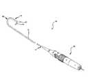
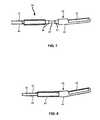
- An example of a steerable ultrasound imaging catheter 1is provided in FIGS. 1 and 2 .
- Such steerable catheters 1included a bendable portion 9 near the ultrasound transducer assembly 4 at the distal end of an elongated catheter body 2 .
- Steeringis achieved by tensioning a steering cable attached at or near the distal portion and running down the interior of the catheter to a wheel or knob in the handle 7 .
- the tipwill deflect resulting in a bend near the distal end of the catheter as illustrated in FIG. 2 .
- the steering cablemay be restrained while the shaft portion 2 is advanced distally, producing the same effect.
- the induced bendhas a radius of curvature of about four inches within an arch defining a plane of fixed orientation with respect to the catheter body 2 and handle 7 .
- the catheter shaft ( 2 )can also be rotated clockwise or counterclockwise to direct the ultrasound transducer face in the desired direction. By rotating the catheter shaft and bending the distal curve 9 the transducer face can be directed as needed.
- Electrical/signal coaxial cables to/from the ultrasound transducer assembly 4pass through the catheter body 2 and through the handle 7 to exit as a cable 8 for connection to ultrasound imaging equipment.
- the steerable ultrasound catheterobviates the need for a sheath and guide wire, the viewing angle of the ultrasound imaging catheter is restricted due to the bend 9 in the catheter that must be made to properly position the ultrasound imaging assembly 4 within a heart chamber. Rotating the catheter shaft by rotating the handle would cause the ultrasound imaging assembly 4 to swing about. As the transducer face is linear and parallel to the catheter shaft, and because the two directional controls are limited, the, current design steerable ultrasound catheters provide a limited three-dimensional viewing perspective.
- the various embodimentsprovide an ultrasound imaging catheter with a pivoting head portion which enables the ultrasound imaging transducer array to be pivoted about a hinge with a near-zero radius of curvature.
- the pivot motion of the ultrasound imaging transducer arrayis controlled from a handle, such as by pivot cables connected to a control wheel in the handle. Pivoting the ultrasound imaging transducer array through a large angle, such as 90° from the centerline of the catheter, enables clinicians to obtain intracardiac ultrasound images from different perspectives without repositioning the catheter itself.
- the ultrasound imaging transducer arrayis capable of being pivoted plus and minus 90° from a center line position (i.e., parallel to the main axis of the catheter).
- the cathetermay also be steerable including a capability of bending a distal portion of the catheter through a finite radius of curvature by steering cables controlled from the handle.
- the cathetermay also be steerable including a capability of bending a distal portion of the catheter through a finite radius of curvature by steering cables controlled from the handle.
- a handle assemblyfeaturing two control actuators for controlling the steering and pivoting mechanisms of the attached catheter.
- the various embodimentsare not necessarily limited to ultrasound imaging catheters, and may be implemented in any catheter that may benefit from having a distal tip capable of pivoting about a hinge.
- FIG. 1is a perspective view of a prior art steerable ultrasound catheter.
- FIG. 2is a perspective view of the steerable ultrasound catheter depicted in FIG. 1 with a bend induced in a distal portion.
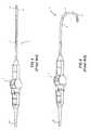
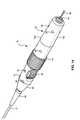
- FIG. 3is a perspective view of an embodiment of the present invention.
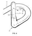
- FIG. 4is a detail of a distal portion of the embodiment illustrated in FIG. 3 .
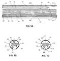
- FIGS. 5A-5Care cross-sectional views of a portion of the embodiment illustrated in FIG. 3 .
- FIGS. 6A-6Eare perspective views of components within a portion of the embodiment illustrated in FIG. 3 .
- FIG. 7is a side view of the distal portion of the catheter embodiment illustrated in FIG. 3 showing a stage of assembly.
- FIG. 8is a side view of the distal portion illustrated in FIG. 7 showing the portion after assembly.
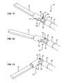
- FIG. 9is a perspective view of an embodiment of the pivot head assembly.
- FIG. 10is a cross-sectional view of the embodiment shown in FIG. 9 .
- FIGS. 11-13are perspective views of another embodiment of the pivot head assembly showing different angles of rotation.
- FIG. 14is a perspective view of a handle portion of the embodiment illustrated in FIG. 3 .
- FIGS. 15-17are cross-sectional views of the handle portion illustrated in FIG. 14 .
- FIGS. 18A-18Care perspective views of the catheter portion of an embodiment illustrating the ultrasound imaging plane at three different angles of rotation.
- FIGS. 19A-19Care perspective views of the catheter portion of an alternative embodiment illustrating the ultrasound imaging plane at three different angles of rotation.
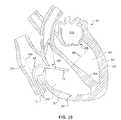
- FIGS. 20 and 21are cross sectional images of a representative heart illustrating an embodiment ultrasound imaging catheter positioned within the right ventricle of a heart by cardiac catheterization via the femoral vein.
- the terms “about” or “approximately” for any numerical values or rangesindicates a suitable dimensional tolerance that allows the part or collection of components to function for its intended purpose as described herein.
- the terms “patient,” “host” and “subject”refer to any human or animal subject and are not intended to limit the systems or methods to human use, although use of the subject invention in a human patient represents a preferred embodiment.
- catheteris used as a general reference to any elongated tubular assembly which may be introduced into an animal or human for medical purposes. Accordingly, references to catheters are not intended to limit the scope of the invention or the claims to any particular forms of catheters, known catheter systems or other subcutaneous medical probes.
- Steerable ultrasound catheters known in the artlimit the degree to which the ultrasound imaging transducer array can be rotated once positioned within a patient's heart. For example, it can be seen in FIG. 20 that once the ultrasound imaging catheter 12 has been positioned within the right ventricle 302 , the bend in a bendable portion 48 of the catheter required to pass the transducer array 18 through the tricuspid valve 309 limits the degree to which the catheter can be turned to adjust viewing angles. In this position, further manipulation of the catheter 12 , such as a rotation, would cause the transducer array portion 18 to stress the tricuspid valve 309 or impact other heart structures.
- the various embodimentsprovide a pivot mechanism coupled to the ultrasound transducer array assembly which is configured to enable a clinician to pivot the transducer array through a sharp angle, such as 90° in either direction with a zero radius of curvature.
- the embodimentsinclude a hinge or pivot joint configured so that the path of the transducer array through the full range of rotation is constrained to a plane with respect to the catheter.
- the pivot motion and rotational position of the transducer array with respect to the cathetercan be controlled by a pivot cable connected to a control actuator (e.g., a wheel coupled to a spool) in a handle assembly.
- the control actuator, handle assembly and pivot headare configured so that a clinician can accurately control the angle of rotation of the transducer array.
- the catheter assemblymay or may not be steerable. If the catheter assembly is steerable, a separate steering mechanism is provided in the handle assembly and coupled to a bendable portion of the catheter which is separate from the pivot head assembly. So configured, the various embodiments enable a clinician to steer the catheter through a patient's vascular structure in order to place the transducer array in a proper position within the patient's body to image a structure of interest, and then pivot the transducer array in order to obtain different imaging perspectives without otherwise repositioning the catheter.
- FIG. 3An embodiment of a steerable catheter assembly 10 is illustrated in FIG. 3 .
- the steerable catheter assembly 10includes an elongated tubular member 12 coupled to a transducer array assembly 18 at the distal end, and to a handle assembly 70 at the proximal end.
- the steerable catheter assembly 10includes a bendable portion 48 which can be controlled from the handle assembly 70 in order to steer the catheter through a patient's vascular structure.
- Coupled between the transducer array assembly 18 and the distal end of the elongated tubular member 12is a pivot head assembly 50 .
- the pivot head assembly 50permits the transducer array assembly 18 to be pivoted through an angle, such as approximately 90° as illustrated in FIG. 3 .
- the pivot head assemblyis positioned at or just beyond the distal end of a bendable portion 48 of the elongated tubular member 12 as illustrated in FIG. 4 .
- the pivot head assembly 50includes a hinge (illustrated in subsequent figures) so that the transducer array assembly 18 can be rotated or pivoted with a zero radius of curvature.
- the bendable portion 48has a radius of curvature that typically will be approximately 4 inches, which is a dimension determined by the typical path requirements of the human vascular structure leading to the heart. In an embodiment illustrated in FIG.
- the pivot head assembly 50may be configured so that the rotational plane through which the transducer array 18 pivots is orthogonal to the plane of curvature of the bendable portion 48 of the elongated tubular member 12 .
- the plane of rotation of the transducer array assembly 18may be parallel to the plane of curvature of the bendable portion of the elongated tubular member 12 or at an angle between parallel and perpendicular.
- the pivot head assembly 50permits the transducer array assembly 18 to be positioned and oriented in a manner that is not achievable using known steerable catheters.
- FIG. 4features a transducer array assembly 18 having a flat face 18 a .
- the transducer array assembly 18includes a cover portion which presents a circular or ovoid cross-section.
- the flat face 18 a shown in FIG. 4is but one embodiment. Nevertheless, this illustration demonstrates a feature of transducer array assemblies typical in ultrasound imaging catheters. Due to the severe space restrictions imposed by the small diameter of intracardiac catheters, the ultrasound imaging transducer is typically limited to a linear phased array made up of several individual transducer elements, such as 64 transducers. The transducers have a flat surface from which sound is omitted and echoed sound is received.
- the individual transducer elementsare pulsed by an ultrasound control system so that the emitted sound waves are constructively combined into a primary beam.
- the ultrasound control systemcan cause the transducer array to omit narrow sound beams which can be swept through an arc in order to obtain a 2D image.
- the transducer arrayemits ultrasound along a plane which is perpendicular to the face of the transducer arrays.
- the transducer array assembly 18emits sound along a plane which is perpendicular to the flat face 18 a the assembly.
- the plane of the 2D ultrasound imageis orthogonal to the plane of the 2-D ultrasound image that will be generated when the ultrasound imaging array 18 is positioned at a zero angle of rotation (i.e., parallel to the centerline of the elongated tubular array 12 ).
- FIG. 4illustrates just one example embodiment, specifically one in which the ultrasound imaging plane is perpendicular to the plane of rotation (i.e., parallel to the axis of rotation of the pivot head assembly 50 ).
- the transducer array assembly 18may be configured to image along planes at a different angle with respect to the plane of rotation, an example of which is described more fully below with reference to FIGS. 19A-19C .
- the elongated tubular member 12 of the catheter assembly 10 of the various embodimentscan range from about 80 cm in insertable length to about 120 cm in insertable length. In one embodiment, the elongated tubular member 12 of the catheter assembly 10 is about 90 cm in length. Some applications, such as veterinarian imaging of large animals (e.g., horses), will benefit from catheters having a longer insertable length. Thus, the elongated tubular member 12 of the catheter assembly 10 , can also be about 100 cm, about 110 cm, about 120 cm, or even longer in length.
- catheters used in intravascular applicationsare at least about 10 French in diameter.
- the electronics and wires needed for ultrasound transducer arrayshave made it impractical and expensive to reduce the size of such catheters below about 10 French. Nevertheless, there are benefits in reducing the diameter of the catheter, and technology advances may enable the electronics and control structures to be further reduced in size.
- the bundling arrangement of the coaxial cables, steering and pivot cables and steering and pivot mechanisms described in more detail belowmake it possible to effectively reduce the diameter below about 10 French, to about 9 French, about 8 French, about 7 French, or even about 6 French (approximately 2 mm). Accordingly, the elongated tubular member 12 of the catheter assembly 10 can range from about 6 to about 12 French in diameter.
- the catheter assembly 10includes an elongated tubular member 12 having a proximal end 14 and a distal end 16 .
- the material for the tubular memberis extruded polyether block amide of the type sold by Atochem North America, Inc. under the trademark PEBAX.
- the tubular membercan be made of PEBAX 7233 having a Shore Durometer hardness of approximately 72 D, PEBAX 7033 having a Shore Durometer hardness of approximately 69 D, PEBAX 6333 having a Shore Durometer hardness of approximately 63 D, PEBAX 5533 having a Shore Durometer hardness of 55 D, PEBAX 4033 having a Shore Durometer hardness of 40 D, PEBAX 3533 having a Shore Durometer hardness of 35 D, or PEBAX 2533 having a Shore Durometer hardness of 25 D.
- Different sections along the length of the tubular member 12can be made from different grades of PEBAX to give the catheter assembly 10 variable flexibility along its length.
- the tubular member 12can also be formed from other materials, such as other polymeric materials that have excellent shape retention characteristics.
- the tubular member 12can be made of polyethylene, silicone rubber, or plasticized PVC.
- the transducer assembly 18can be formed from an array of individual ultrasound elements as is well known in the art. There may be forty-eight or more such ultrasound elements 20 that form the transducer assembly 18 . In a preferred embodiment the transducer assembly 18 is a sixty-four element linear phased array ultrasound imaging sensor.
- One example of an ultrasound transducer that can be incorporated into the catheter assembly 10is the ultrasound imaging catheter marketed under the trademark ViewFlex® by EP MedSystems, Inc. of West Berlin, N.J.
- the transducer assembly 18may include other electronics, such as a temperature sensor (e.g., a thermistor) as disclosed in U.S. Pat. No. 6,908,434 entitled “Ultrasound Imaging Catheter Isolation System With A Temperature Sensor,” the entire contents of which are hereby incorporated by reference.
- a temperature sensore.g., a thermistor
- the elongated tubular member 12may include a section that is configured to preferentially bend or bend in response to tensions applied by steering cables so as to provide improved catheter maneuverability and to decrease the risk of damage to an anatomical structure, such as a blood vessel or heart chamber during advancement of the catheter tip.
- an anatomical structuresuch as a blood vessel or heart chamber during advancement of the catheter tip.
- the catheter assembly 10will tend to bend at that more flexible portion when a force is applied (e.g., from encountering an obstruction or from tension applied to an internal steering cable).
- the Shore Durometer hardness of the material forming the flexible tubular portion 22can be about 35 D to 63 D, or more preferably about 40 D to about 55 D.
- a bendable portion subassembly 48 illustrated in FIGS. 6A-6Eis configured with a flexible tubular portion 22 and other structures so that a bend in that portion can be controlled by tension applied through steering cables 42 , 44 .
- a flexible tubular portion 22is included in or attached to the elongated tubular member 12 so that when the catheter assembly is advanced through a patient's vascular structure, the tubular member 12 bends freely at the flexible tubular portion 22 when the distal tip of the transducer assembly 18 contacts a vessel wall.
- the handle assembly 70can include a steering control mechanism such as a rotatable control knob, handle or wheel, slide actuator, or other suitable manipulating member that controls tension applied to one or more steering cables 42 , 44 that extend through the lumen of the tubular member 12 to a point near the distal end of a bendable portion subassembly 48 for controlling the bending movement of the catheter proximate the transducer assembly.
- a steering control mechanismsuch as a rotatable control knob, handle or wheel, slide actuator, or other suitable manipulating member that controls tension applied to one or more steering cables 42 , 44 that extend through the lumen of the tubular member 12 to a point near the distal end of a bendable portion subassembly 48 for controlling the bending movement of the catheter proximate the transducer assembly.
- the transducer array assembly 18is coupled to the pivot head assembly 50 as described in more detail below with reference to FIGS. 9-11 .
- This creates a pivoting transducer assembly 67illustrated in FIGS. 7 and 8 , from which extends a bundled 30 of coaxial cables, a pivot cable conduit 60 including one or more pivot cables 62 , 64 , and any other electrical leads connected to the transducer array assembly 18 .
- This assemblycan then be coupled to the bendable portion 48 which is coupled to the elongated tubular member 12 as described more fully below.
- FIG. 5Ashows a lateral cross section of the tubular member 12 .
- FIGS. 5B and 5Cshow cross sectional views of the tubular member 12 at the indicated cross sections 5 B and 5 C, respectively.
- the elongated tubular member 12is hollow and has a lumen extending therethrough. Nested within the lumen of the elongated tubular member 12 is a bundle 30 of electrical cables 26 , a steering cable conduit 43 for one or more steering cables 42 , 44 , and a pivot cable conduit 60 including one or more pivot cables 62 , 64 .
- the electrical cables 26are coaxial cables suitable for use with ultrasound transducers.
- the cable bundle 30is formed by bundling together all of the coaxial cables 26 that are necessary to operate the transducer assembly 18 .
- the bundle 30will preferably carry a corresponding number of coaxial cables 26 to match the number of elements in the transducer. For example, if the transducer assembly 18 is a forty-eight element transducer, then generally forty-eight coaxial cables 26 will form the bundle 30 , and if the transducer assembly 18 is a sixty-four element transducer, then generally sixty-four coaxial cables 26 will form the bundle 30 .
- the transducer assembly 18can have a sixty-four element parallel drive phased array, in which case the bundle 30 has at least sixty-four coaxial cables 26 .
- the cross-sectional diameter of the catheter assembly 10can be reduced by reducing the number of coaxial cables 26 and, correspondingly, the number of elements in the transducer assembly 18 . It should be appreciated that none of the embodiments described herein are limited by the number of elements in the transducer assembly 18 . It should be further appreciated that in other forms of catheters, such as ablation and electrophysiology catheter embodiments, the electrical cables 26 will be configured as appropriate for connecting sensor or therapy elements to external equipment, and may be coaxial, twisted pair, dual stranded or single stranded electrical conducting cables as appropriate to such applications.
- the coaxial cables 26are bundled within a protective sheath 28 forming an ovular or rectangular cross-section.
- the protective sheath 28may be formed from polyamide or PVC.
- the bundle 30can include various types of filler material (not shown), such as Pebax, to provide the catheter assembly 10 with different shape retention and rigidity characteristics.
- the coaxial cablesare spun together along with one or more filler materials to form a bundle 30 having an ovular or rectangular cross-section.
- a hollow steering cable conduit 43includes a lumen that carries one or more steering cables 42 and 44 .
- a hollow pivot cable conduit 60includes a lumen that carries one or more pivot cables 62 , 64 .
- the steering cables 42 and 44are nested together and the pivot cables are nested together along most of the length of the elongated tubular member 12 .
- the steering cables 42 and 44may diverge as illustrated at cross section 5 C.
- Steering cable 42remains on one side of the bundle 30 , while steering cable 44 is threaded around the bundle 30 to the other side thereof.
- that steering cable 42applies a corresponding pulling force to one side of the distal end of the elongated tubular member 12 , thus bending the distal end of the catheter assembly 10 in one direction along a plane identified by line 29 shown in FIG. 5C .
- the rectangular or oval shape of the cable bundle 30helps constrain the bending of the bendable portion 48 .
- the bundle 30will preferentially or selectively bend in two directions that are approximately 180° opposite each other along the plane identified by line 29 in FIG. 5C . That is, under an applied force, the cable bundle 30 will bend about the longer sides of the oval or rectangle and resist bending along the shorter sides.
- shape memory filler materialmay be incorporated into the bundle 30 to help retain a bend until a pulling force applied to the steering cable 44 applies an opposite force to the distal end of the elongated tubular member 12 causing the bendable portion 48 to return to a straight configuration or to another bend configuration within the bending plane 29 .
- shape memory filler materialis not incorporated into the bundle 30 , and a pulling force must be maintained in order to maintain the bend at the distal end of the catheter assembly 10 .
- the ovular or rectangular cross-section of the bundle 30provides ample space on the long sides of the rectangle for additional wiring, such as the steering cable conduit 43 , the pivot cable conduit 60 , working elements or tools, and wiring from additional sensors, such as for example temperature sensors (e.g., a thermister) and/or electrodes (e.g., electrophysiology electrodes).
- additional sensorssuch as for example temperature sensors (e.g., a thermister) and/or electrodes (e.g., electrophysiology electrodes).
- FIGS. 6A through 6Eillustrate the bending portion subassembly 48 of the catheter assembly 10 proximal the transducer assembly 18 .
- This bending portion subassembly 48provides the attachment point for the steering cables 42 , 44 and the flexible tubular member 22 that enable inducing a controllable bend in the catheter assembly 10 .
- the bending portion subassembly 48includes a small hollow cylinder 34 coupled to the flexible tubular member 22 (shown in FIG. 6B ) at the distal end.
- the flexible tubular member 22may be, for example, silicon, Pebax or polyethylene with an outside diameter of about 9 French and about 1 to about 8 inches in length.
- the hollow cylinder 34includes holes 36 and 38 formed in the outer wall to which a steering cable 40 can be connected.
- one steering cable 40passes through the interior of the cylinder 34 , out of the hole 36 , around the outer circumference of the cylinder 34 and back through the hole 38 to the interior or lumen of the cylinder 34 .
- two steering cables 42 , 44are essentially formed from the opposite ends 42 and 44 of a single steering cable 40 . These two steering cable ends 42 and 44 are lead down through the lumen of the elongated tubular member 12 to the handle assembly 70 , where the steering cables are coupled to a steering mechanism described below with reference to FIGS. 14-17 .
- the steering mechanismasserts a pulling force against one of the two steering cables, such as steering cable 42 , for example, the steering cable 42 pulls on the cylinder 34 at hole 36 causing the cylinder to twist toward the tensioned steering cable 42 .
- the force on the cylinder 34causes the flexible tubular member 22 to bend in a first direction towards steering cable 42 .
- the distal portion of the catheter assembly 10forms a bend in the first direction.
- the steering mechanismapplies a pulling force on the other steering cable 44
- the steering cable 44pulls on the cylinder 34 on the side of the other hole 38 , causing the flexible tubular member 22 to bend in a second direction opposite the first direction toward steering cable 44 .
- the two steering cable ends 42 and 44are connected, such as by fusing or tying the ends, forming a single, elongated loop within the catheter assembly 10 .
- the steering cable elongated loopmay be wrapped around a pulley or spindle, for example, in the steering mechanism within the handle assembly 70 which can be turned, such as by the operator turning an attached handle or wheel, to exert a pulling force on one side of the elongated loop while letting out the other side of the elongated loop.
- two separate steering cablesare used rather than looping one steering cable over cylinder 34 .
- a distal end of the first steering cableis threaded through the cylinder 34 and out the hole 36 .
- the distal end of the first steering cableis secured to the outer wall of the cylinder 34 adjacent the hole 36 by an adhesive, enlarged knot, wrapping it around a screw fastened to the cylinder 34 or other means.
- a distal end of the second steering cableis threaded through the cylinder 34 and out the hole 38 .
- the distal end of the second steering cableis secured to the outer wall of the cylinder 34 adjacent the hole 38 by an adhesive, enlarged knot, wrapping it around a screw fastened to the cylinder 34 or other means.
- each of the steering cablesare threaded through the lumen of the elongated tubular member 12 , such as through the steering cable conduit 43 , out the proximal end of the elongated tubular member 12 , and connected to the steering mechanism within the handle assembly 70 .
- the one or more steering cables 42 , 44may comprise a strand, wire, and/or thread, and is preferably made from low profile, durable, non-elastic and non-conducting material.
- the steering cable(s)can be made of synthetic materials, such as nylon or similar synthetic fibers, or plastics material, such as urethane, Teflon®, Kynar®, Kevlar®, polyethylene, multistranded nylon, or gel-spun polyethylene fibers.
- the steering cablesmay be multistranded Spectra® brand nylon line sold as Spiderwire® fishing line (10 lbs. test).
- the flexible tubular member 22is connected to the cylinder 34 , by inserting the proximal end of the cylinder 34 through the distal end of the flexible tubular member 22 as illustrated in FIG. 6E . Thereafter, an adhesive or fastener (not shown) may be applied to the area where the steering cable 40 abuts the distal end of the flexible tubular member 22 to fix the steering cable 40 and cylinder 34 in place against the flexible tubular member 22 .
- the flexible tubular member 22 and cylinder 34may be frictionally engaged, with the opposite ends of the steering cable 40 immovably trapped between the lumen of the flexible tubular member 22 and the outer wall of the cylinder 34 .
- the subassemblyis slid over the proximal end of the cable bundle 30 and is moved toward the ultrasound transducer assembly 18 as shown in FIGS. 7 and 8 .
- the distal end of the cylinder 34may fit over a support cylinder 32 coupled to the proximal end of the pivot head assembly 50 .
- the pivot head assembly 50may include a recessed fitting to receive the cylinder 34 .
- the steering cable end 42is positioned so that it is aligned with one of the long sides of the ovular or rectangular of the cable bundle 30 .
- the other steering cable end 44is positioned so that it is aligned with the other long side of the ovular or rectangular cross-section cable bundle 30 . This can be achieved by aligning the holes 36 and 38 with the long sides of the cable bundle 30 when the subassembly 48 is slid over the cable bundle 30 and steering cable ends 42 and 44 and connected to the transducer assembly 18 .
- a cylindrical connector member(not shown) similar to the cylinder 34 but without the holes in the side walls can be guided over the proximal ends of the cable bundle 30 and steering cable ends 42 and 44 and into the lumen of the flexible tubular member 22 .
- the outer diameter of the cylindrical connector membercan be just slightly smaller than the diameter of the lumen of the flexible tubular member 22 so that it can slide into the flexible tubular member 22 .
- the last step of assembling the catheter portion of the catheter assembly 10involves the elongated tubular member 12 , which forms the outer surface of the catheter assembly 10 .
- the elongated shaft 12has an outer diameter of about 6 French to about 9 French, and an inner diameter large enough to encompass the cable bundle 30 , steering cable and pivot cable conduits 43 , 60 , and any other included wires (not shown).
- the elongated tubular member 12is guided over the cable bundle 30 and cable conduits 43 , 60 .
- the elongated tubular member 12is pushed forward until its distal end over the cylindrical connector member and abuts the proximal end of the flexible tubular member 22 .
- the distal end of the cylindrical connector membermay be secured to the flexible tubular member 22 using an adhesive on the outer wall of the cylindrical connector member, on the inner luminal wall of the flexible tubular member 22 or at the interface between the two tubular members.
- the cylindrical connector membermay be secured to the inner luminal wall of the flexible tubular member 22 through friction or mechanical collar or latch (not shown).
- the pivot head assembly 50includes a hinge or pivot point, an example of which is illustrated in FIG. 9 .
- the hingecomprises a pintle 51 forming a flexible joint between an inner hinge support member 57 coupled to a base member 59 and outer hinge support members 53 coupled to a proximal end of the transducer array assembly 18 .
- the hingemay be configured so that the inner hinge support member 57 can slip between the two outer hinge support members 53 with minimal friction but with sufficient lateral support so that the transducer array assembly 18 is constrained to pivot about the pintle 51 within a plane.
- the two outer hinge support members 53include a through hole into which the pintle 51 is inserted.
- the pintle 51may be held in position in the two outer hinge support members 53 by friction, adhesive, a spring clip, a cap over the holes, or other means.
- a lubricant or a low friction surfacesuch as Teflon®, may be deposited on the inner surfaces of the two outer hinge support members 53 , on a central portion of the pintle 51 and/or on the surfaces of the inner support member.
- the base member 59may be configured to couple to the bending portion subassembly 48 , such as by fitting over the support cylinder 32 as illustrated in FIGS. 7 and 8 .
- the base memberwhen assembled to the bending portion subassembly 48 the base member may abut the flexible tubular member 22 as illustrated in FIGS. 8 and 9 .
- the bundle 30 of coaxial cables 26 and other electrical wires running from the transducer array assembly 18are fed between the transducer array assembly 18 and the base member 59 with sufficient play to enable the pivot head to traverse a full 180° (i.e., 90° in either direction from 0° deflection) without binding or disconnecting any cable from the transducer array.
- the bundle 30is omitted from FIG. 9 so that the structure of the hinge can be illustrated.
- Pivot cables 62 , 64extend from the base member 59 on either side of the inner hinge support member 57 .
- the pivot cables 62 , 64are connected to one or both of the two outer hinge support members 53 so that when one of the pivot cables is placed in tension the pivot head assembly 50 pivots the transducer array 18 about the pintle 51 .
- the pivot cables 62 , 64may comprise a strand, wire, and/or thread, and are preferably made from low profile, durable, non-elastic and non-conducting material.
- the pivot cables 62 , 64can be made of synthetic materials, such as nylon or similar synthetic fibers, or plastics material, such as urethane, Teflon®, Kynar®, Kevlar®, polyethylene, multistranded nylon, or gel-spun polyethylene fibers.
- the steering cablesmay be multistranded Spectra® brand nylon line sold as Spiderwire® fishing line (4-10 lbs. test).
- FIG. 10An example of how the pivot cables 62 , 64 may be connected to one or both of the two outer hinge support members 53 is shown in FIG. 10 .
- the pivot cables 62 , 64connect to opposite sides of the two outer hinge support members 53 and loop around the pintle 51 so that a full 180° of rotation can be accomplished by tensioning one or the other of the two pivot cables 62 , 64 .
- tensioning pivot cable 64causes the transducer array assembly 18 to pivot from 0° deflection to a positive 90° deflection as illustrated.
- the other pivot cable 62is allowed to loop under one of the two outer hinge support members 53 .
- pivot cable 62has leverage on the outer hinge support member 53 so that when it is tensioned, the transducer array assembly 18 can be deflected from positive 90° deflection all the way around to ⁇ 90° deflection.
- the routing of pivot cables 62 , 64 illustrated in FIG. 10is but one illustration of how pivot cables can be connected to the transducer array assembly 18 , and is not intended to be limiting.
- FIGS. 11-13An alternative configuration embodiment for the hinge or pivot joint is illustrated in FIGS. 11-13 .
- the hinge in this embodimentis formed from a proximal hinge support member 56 coupled to the base member 59 , a distal hinge support member 55 and a pintle 51 positioned within tubular portions 56 a and 55 a of the proximal hinge support member 56 and distal hinge support member 55 , respectively.
- a through hole 52 in each of the proximal and distal hinge support members 56 , 55is provided to accept the pintle 51 with sufficient clearance to enable low friction rotation, but with sufficient diameter to constrain the rotation of the transducer array assembly 18 to a plane perpendicular to the through hole 52 axis.
- Lubricant or low friction materialssuch as Teflon®, may be provided in the inner surface of the through hole 52 , on the surfaces of the pintle 51 , and/or the interfacing surfaces between the tubular portions of the proximal and distal hinge support members 56 , 55 .
- the pintle 51may be held in place within the through hole 52 by a spring clip, adhesive, cap, or other known mechanisms for retaining a pin within a hole.
- the pintle 51may be integral to one of the proximal or distal hinge support members 56 or 55 and configured to fit within a through hole 52 within the other support member.
- the base member 59may be configured to easily couple to the rest of the catheter assembly 10 so that the base member 59 abuts the flexible tubular member 22 as illustrated.
- the pivot cables 62 , 64may connect to an outer surface of the distal support member 55 , such as by being threaded through a hole 54 and secured in place, such as by use of an adhesive, a large knot, or an end cap on the pivot cable 62 .
- the pivot cable 62may pass through the hole 54 , laterally across the distal hinge support member 55 and out a hole (not shown) on the other side to exit as pivot cable 64 . So configured, tensioning of one pivot cable 62 , 64 will cause the distal portion of the pivot head assembly to rotate in the direction of the tensioned cable. This is illustrated in FIGS. 12 and 13 which show the transducer array assembly 18 rotating through an angle in response to tension applied to pivot cable 62 .
- FIGS. 12 and 13show the transducer array assembly 18 rotating through an angle in response to tension applied to pivot cable 62 .
- the pivot cablesmay cross within the space between the hinge point in the base member 59 so that they enter the base member 59 on opposite sides similar to the arrangement illustrated in FIG. 10 .
- the coaxial cable bundle 30is omitted from FIGS. 11-13 so that the structural details of the pivot head assembly 50 can be seen. However, the cable bundle 30 will be positioned to pass around the pivot joint (i.e., elements 51 , 55 a and 56 a ) with sufficient slack so that the transducer array assembly 18 can be rotated through a full 180° without tensioning the cable bundle 30 .
- the transducer array assembly 18 and pivot head assembly 50may be assembled as a first step in the assembly of the catheter assembly 10 . Cables leading from the transducer array assembly 18 are threaded around the pivot joint and through the base member 59 . Pivot cables 62 , 64 are attached to the distal hinge support member 55 and threaded through the base member 59 .
- the hingeis assembled by positioning the hinge members (either the inner and outer hinge support members 53 , 57 , or the proximal and distal hinge support members 56 , 55 ) to align the hinge through holes 52 and slipping the pintle 51 into the aligned through holes. Finally, the pintle 51 is retained within the hinge joint, such as by positioning spring clips on or caps over the ends of the pintle 51 .
- the transducer array assembly 18 and pivot head assembly 50may be covered by one or more protective coverings which are omitted from FIGS. 11-13 in order to reveal the details of the pivot head assembly 50 .
- a protective covering or coveringsmay be one or more closed end tubular members which may be made from any of the materials described herein for the various sections of the catheter assembly 10 .
- An acoustic windowmay be provided on the distal end of the protective covering configured from materials that have the appropriately acoustic characteristics to provide a proper acoustic coupling between the transducer array assembly 18 on the inside and body fluids on the outside.
- a flexible portion of the protective coveringmay be positioned over the pivot joint part of the pivot head assembly 50 .
- the protective coveringmay be fused or coupled to the rest of the catheter assembly (e.g., by frictional couplings or adhesives). Once the protective covering is in place over the transducer array assembly 18 and pivot head assembly 50 and fused to the rest of the catheter assembly 10 , the distal end of the catheter assembly will be smooth and sealed to prevent intrusion by body fluids.
- FIG. 14illustrates an embodiment of the handle assembly 70 .
- the handle assembly 70includes a grip portion 72 , a steering control manipulator 74 and a pivot control wheel 78 .
- the steering control manipulator 74is configured as a rotatable cylinder which is coupled by a screw mechanism to a slide actuator which is shown in more detail in FIGS. 15 and 17 .
- the steering control manipulator 74may be in the form of a slide or control wheel positioned within the handle as is known in the art.
- the pivot control wheel 78is configured as two coaxial wheels in this embodiment each rotating about an axle positioned within an axle support hole 79 within a pivot wheel support structure 76 .
- the pivot control wheel 78is accessible through openings 120 (shown in FIG. 17 ) on opposing sides of the handle assembly 70 . So configured, the pivot control wheel 78 can be actuated by either the left or right hand, allowing left- and right-handed clinicians to manipulate the control wheel with one hand and without having to switch hands.
- the handle assembly 70may also include a transition region cover 80 and a catheter transition piece 82 which together ensure a structural and functional transition from the elongated tubular member 12 to the handle assembly 70 .
- a cable support structure 84At the proximal end of the handle assembly 70 is a cable support structure 84 through which electrical cables 86 are passed.
- the electrical cables 86contain all of the coaxial and other electrical connectors linked to the transducer array assembly 18 .
- the electrical cables 86extend to a connector (not shown) which is structured to connect to ultrasound imaging equipment, such as an ultrasound imaging system isolation box assembly as described in U.S. patent application Ser. No. 10/998,039 entitled “Safety Systems and Methods for Ensuring Safe Use of Intracardiac Ultrasound Catheters,” published as U.S. Patent Application Publication No. 2005/0124899, the entire contents of which are hereby incorporated by reference.
- the handle assembly 70may be configured in pieces to aid fabrication and assembly.
- the grip portion 72may be fabricated in upper and lower portions 72 a , 72 b , which can be fit together and secured using threaded fasteners through faster holes 90 .
- FIG. 15Such construction is illustrated in FIG. 15 which reveals internal structures of the handle assembly 70 with the upper grip portion 72 a portion of the handle structure removed.
- the cable support structure 84may be configured as a cylinder with ridges configured to fit within corresponding grooves within the upper and lower grip portions 72 a , 72 b .
- the cable support structure 84may include internal structures for transitioning the cable bundle 32 into an external cable having the necessary insulation, RF shielding and protective layers so that the electrical cables 86 complies with requirements for electrical cables used in medical devices.
- the cable support structure 84may include internal structures to ensure that tensions and torque applied to the external electrical cables 86 is not transmitted to the relatively fragile internal cable bundle 30 .
- the cable bundle 30extends along the centerline of the handle assembly 70 from the cable support structure 84 through to a cable transition portion 94 where the cable bundle 30 is joined with the steering and pivot cables before entering into the proximal end 92 of the elongated tubular member 12 .
- FIG. 15reveals how the steering control manipulator 74 interfaces with a slide actuator 98 within a slide slot 102 of an inner support structure 100 .
- the steering control manipulator 74includes internal threads 75 (shown in FIG. 17 ) which engage the partial threads on the slide actuator 98 .
- the internal threads 75cause the slide actuator 98 to move longitudinally (i.e., proximally or distally) within the slot 102 .
- Longitudinal movement of the slide actuator 98causes one of the steering cables 42 , 44 to be tensioned while the other cable is loosened.
- rotational movement of the steering control manipulator 74can be translated into bending forces applied to the bendable portion subassembly 48 as described above.
- FIG. 15also reveals how the pivot control wheel 78 may be comprised of upper and lower pivot control wheels 78 a , 78 b each rotating about an axel 96 .
- Rotation of the upper and lower pivot control wheels 78 a , 78 bdrive rotation of a spool 110 (shown in FIG. 16 ) for controlling the tensioning of pivot cables as shown in more detail in FIG. 16 .
- the pivot control wheel 78On the distal side of the pivot control wheel 78 may be positioned a transition region 94 within the transition region cover 80 in which the various internal parts of the catheter assembly are brought together prior to entering into the elongated tubular member 12 .
- the cable bundle 30 , the steering cables 42 , 44 (if present), pivot cables 60 2 , 64 , and other electrical leadsare configured into an arrangement suitable for being threaded into the elongated tubular member 12 .
- the steering cables 42 , 44may thread into the steering cable conduit 43
- the pivot cablesmay threaded into the pivot cable conduit 60 .
- FIG. 16shows the assembly with the control manipulator 74 and the upper pivot control wheel 78 a removed.
- the grip portion 72may extend over the proximal portion of the handle assembly 70 .
- the internal support structure 100 supporting the slide actuator 98 and associated internal mechanisms for controlling steering cable tensionmay be configured to extend beyond the grip portion 72 , couple to a ring support 114 for the control manipulator 74 , and couple to the proximal end of the pivot wheel support structure 76 .
- the ring support 114provides a bearing support for the control manipulator 74 to permit the manipulator cylinder to be rotated smoothly in either direction.
- the ring support 114may be coupled to the internal support structure 100 by threaded connectors, adhesives or other known methods for coupling structures together.
- the internal support structuremay be formed in two halves as illustrated in FIG. 16 to facilitate assembly.
- the internal support structure 100also provides a slot 102 for constraining the lateral movement of the slide actuator 98 .
- FIG. 16reveals details of the pivot cable tensioning spool 110 which couples to the upper and lower pivot control wheels 78 a - 78 b by dowels 112 .
- the pivot cable tensioning spool 110may comprise an upper and lower spool between which the cable bundle 30 can pass.
- One of the pivot cables 62 or 64is wound about the upper pivot cable tensioning spool 110 in the clockwise direction, while the other pivot cable 62 or 64 is wound about the lower pivot cable tensioning spool 110 in the counterclockwise direction. In this manner, rotation of the pivot control wheels 78 causes one of the pivot cables to be tensioned while the other pivot cable is loosened.
- the handle assembly 70may also include a steering cable bypass guide structure 106 which serves to route the steering cables 42 , 44 around the pivot cable tensioning spool 110 .
- This structuremay include a guide plate 104 for redirecting the steering cables in line with the cable bundle 30 prior to entering into the proximal end 92 of the elongated tubular member 12 .
- the structuremay include a proximal guide 108 to past the steering cables smoothly through the transition provided in the internal support structure 100 before they are connected to the slide actuator 98 .
- FIG. 16also reveals how the pivot wheel support structure 76 may be fabricated in two halves which can be coupled together by threaded fasteners through the fastener holes 90 .
- the lower pivot control wheel 78 bcan be lowered into position and rotatably coupled to the lower pivot wheel support structure 76 a by an axel 96 which engages an axel support hole 79 (shown in FIG. 14 ).
- the axel 96may include a central shaft having a through hole for accommodating the cable bundle 30 .
- the lower pivot cable tensioning spool 110can be positioned in the lower pivot control wheel 79 b , after which the cable bundle 28 may be threaded through the assembly before the upper pivot cable tensioning spool 110 is positioned in place.
- the steering cable bypass guide structure and guide platesmay be positioned around the cable tensioning spool 110 and the steering cables routed through the structure to extend into the internal structure 100 .
- the upper pivot control wheel 78is installed on the upper pivot cable tensioning spool 110 by sliding over the dowels 112 , and the upper pivot wheel support structure (not shown separately).
- the upper pivot wheel support structureis attached to the lower pivot wheel support structure 76 a such as by using threaded fasteners through fastener holes 90 .
- the pivot wheel support structure 76may then be joined to the internal structure 100 , such as by threaded fasteners, locking joints or adhesives.
- FIG. 17is a lateral cross-section view of the handle assembly 70 which reveals other internal structure details of illustrated embodiment.
- the internal support structure 100may be configured with tangs and grooves to engage corresponding structures in the grip portion 72 in order to firmly position in the two pieces together.
- the slide actuator 98may include a portion 118 which extends radially inward between the two halves of the internal support structure 100 in order to engage the steering cables (not shown in FIG. 17 ).
- FIG. 17also reveals the internal threads 75 on the steering control manipulator 74 .
- FIG. 17shows how the axel 96 engages the axel support hole 79 within the pivot wheel support structure 76 .
- FIG. 17shows a two part axel 96 with a lower axel piece 96 a shown in place, while the upper axel piece 96 is removed in order show further details about the structure.
- the axel 96may be provided as a single member which engages both the upper and lower portions of the pivot wheel support structure 76 .
- FIG. 17also reveals the opening 120 in the pivot wheel support structure 76 for accommodating the pivot control wheels 78 .
- FIG. 17also shows a cross-sectional view of the catheter transition piece 82 which may be a tubular member made of flexible material similar to that of the elongated tubular member 12 .
- the catheter transition piece 82With a diameter which tapers gradually from the proximal end to the distal end, the catheter transition piece 82 can transition bending stresses so that the elongated tubular member 12 is rigidly supported as it enters the transition region cover 80 without applying a bending force with a sufficiently small radius of curvature to cause the elongated tubular member 12 to kink.
- a flange and groove attachment configuration 112may be provided for attaching the catheter transition piece 82 to the transition region cover 80 .
- FIGS. 18A-18CA key operational advantage provided by the various embodiments is illustrated in FIGS. 18A-18C .
- These figuresillustrate the catheter assembly as it may appear when placed within a patient during the conduct of ultrasound imaging.
- the bendable portion assembly 48 of the catheteris bent as may be necessary to position the transducer array assembly 18 within a patient's heart.
- the transducer array assembly 18can obtain 2-D ultrasound images along the imaging plane 68 , which in this illustration is shown as normal to the plane of the paper.
- a clinicianmay need to obtain a second 2-D ultrasound image along an orthogonal imaging plane. To do so, the clinician actuates the pivot head assembly 50 (as described more fully above with reference to FIGS.
- FIG. 18Billustrates, the ultrasound imaging planes 68 is now oriented at right angles to the imaging claim illustrated in FIG. 18A .
- an orthogonal 2D ultrasound imagecan be obtained without any movement or other manipulation of the catheter assembly 10 which would fundamentally change the viewing perspective.
- the clinicianis able to obtain two orthogonal 2D ultrasound images of the same region of interest.
- the clinicianmay also obtain imagery at any angle between the 0° and 90° deflections illustrated in FIGS. 18 A.- 18 B.
- the clinicianmay manipulate the pivot head assembly 50 to cause the transducer array assembly 18 to pivot through 90° in the opposite direction as illustrated in FIG. 18C .
- Cliniciansmay also benefit from obtaining a 180° scan of ultrasound images of a structure of interest by incrementally rotating the transducer array assembly from the position illustrated in FIG. 18B to the position illustrated in FIG. 18C .
- FIGS. 19A-19Cshow an embodiment in which the transducer array assembly 18 is oriented so that the 2-D ultrasound imaging plane 68 is parallel to the rotation plane of the pivot head assembly 50 .
- the transmission surface of the transducer array assembly 18is perpendicular to the plane of rotation.
- rotation of the pivot head assembly 50enables the transducer array assembly 18 to provide ultrasound images which pan through 180°.
- the ultrasound transducer array 18can provide the clinician with ultrasound images of all structures surrounding the pivot head assembly 50 within the imaging plane.
- a catheter assembly 10may be beneficial in diagnostic procedures where the clinician needs to conduct a survey of the heart and does not have a particular structure of interest at the start of the exam.
- This embodiment catheter assembly 10may be used in procedures in combination with the previously described embodiment catheter, with one type of catheter used to conduct a broad survey of the patient's heart and the other catheter used to obtain orthogonal imagery as may be necessary for certain procedures, such as ventricle ejection fraction estimation.
- FIGS. 20 and 21illustrate the transducer array assembly 18 positioned within the right ventricle 302 of a patient's heart 301 .
- the elongated tubular member 12can be introduced into the patient's vascular structure via the femoral vein.
- a cliniciancan advance the distal portion of the catheter into the right atrium 304 .
- the clinicianmay rotate the steering control mechanism 74 in order to introduce a bend into the bendable portion subassembly 48 .
- the clinicianmay also rotate the entire catheter assembly 10 by rotating the handle assembly 70 in order to orient the bend as necessary to align with the twists and turns in the vascular structure.
- the clinicianmay rotate the steering control mechanism 74 so as to introduce an acute bend in the bendable portion subassembly 48 in order to direct the transducer array assembly 18 through the tricuspid valve 309 and into the right ventricle 302 , as shown in FIG. 20 .
- the field of view of the transducer array assembly 18can include portions of the right ventricle 302 , the septum 306 , the left atrium 310 , the bicuspid valve 308 , the left ventricle 303 , and the left ventricular wall 305 . If the transducer array assembly 18 is directed the other way (e.g., if the catheter assembly 10 is turned 180 degrees) the right ventricle 302 and right ventricular wall 307 can be imaged. It is worth noting that if the clinician were to twist the catheter assembly 10 while the catheter is positioned as illustrated in FIG.
- the transducer array assembly 18would swing about the long axis 12 a of the elongated tubular member 12 , which could injure the tricuspid valve 309 or cause the transducer array assembly 18 to strike the right ventricular wall 307 or the septum 306 .
- the cliniciancan rotate the pivot control wheel 78 in order to cause the transducer array assembly 18 to pivot approximately 90° as illustrated in FIG. 21 .
- a 2D ultrasound imagecan be obtained along with the image plane illustrated by the dashed line 68 .
- the 2-D ultrasound image planeis perpendicular to the surface of the paper and extends through an angle which allows imaging of portions of the right ventricle 302 , the septum 306 , and the left atrium 310 .
- FIGS. 20 and 21illustrate accessing a patient's heart via the femoral vein
- accessmay also be obtained through the jugular or subclavian veins in which case the elongated tubular member 12 would be introduced through the superior vena cava and from the top of the right atrium 304 .
- the pivot head assembly and associated structuresmay also be used in other catheter applications where a zero radius of curvature bend or pivot is required.
- the present inventionis not necessarily limited to ultrasound imaging catheters, and may be implemented in any catheter that may benefit from having a distal tip capable of pivoting about a hinge.
Landscapes
- Health & Medical Sciences (AREA)
- Life Sciences & Earth Sciences (AREA)
- General Health & Medical Sciences (AREA)
- Biophysics (AREA)
- Engineering & Computer Science (AREA)
- Veterinary Medicine (AREA)
- Biomedical Technology (AREA)
- Heart & Thoracic Surgery (AREA)
- Public Health (AREA)
- Animal Behavior & Ethology (AREA)
- Nuclear Medicine, Radiotherapy & Molecular Imaging (AREA)
- Physics & Mathematics (AREA)
- Pathology (AREA)
- Radiology & Medical Imaging (AREA)
- Medical Informatics (AREA)
- Molecular Biology (AREA)
- Surgery (AREA)
- Hematology (AREA)
- Anesthesiology (AREA)
- Cardiology (AREA)
- Pulmonology (AREA)
- Gynecology & Obstetrics (AREA)
- Ultra Sonic Daignosis Equipment (AREA)
Abstract
Description
Claims (20)
Priority Applications (4)
| Application Number | Priority Date | Filing Date | Title |
|---|---|---|---|
| US12/107,759US8052607B2 (en) | 2008-04-22 | 2008-04-22 | Ultrasound imaging catheter with pivoting head |
| EP09733751AEP2190354A4 (en) | 2008-04-22 | 2009-04-22 | Ultrasound imaging catheter with pivoting head |
| JP2011506427AJP2011518031A (en) | 2008-04-22 | 2009-04-22 | Ultrasound imaging catheter with swivel head |
| PCT/US2009/041425WO2009132117A2 (en) | 2008-04-22 | 2009-04-22 | Ultrasound imaging catheter with pivoting head |
Applications Claiming Priority (1)
| Application Number | Priority Date | Filing Date | Title |
|---|---|---|---|
| US12/107,759US8052607B2 (en) | 2008-04-22 | 2008-04-22 | Ultrasound imaging catheter with pivoting head |
Publications (2)
| Publication Number | Publication Date |
|---|---|
| US20090264759A1 US20090264759A1 (en) | 2009-10-22 |
| US8052607B2true US8052607B2 (en) | 2011-11-08 |
Family
ID=41201696
Family Applications (1)
| Application Number | Title | Priority Date | Filing Date |
|---|---|---|---|
| US12/107,759Expired - Fee RelatedUS8052607B2 (en) | 2008-04-22 | 2008-04-22 | Ultrasound imaging catheter with pivoting head |
Country Status (4)
| Country | Link |
|---|---|
| US (1) | US8052607B2 (en) |
| EP (1) | EP2190354A4 (en) |
| JP (1) | JP2011518031A (en) |
| WO (1) | WO2009132117A2 (en) |
Cited By (41)
| Publication number | Priority date | Publication date | Assignee | Title |
|---|---|---|---|---|
| US20110213347A1 (en)* | 2006-07-11 | 2011-09-01 | Cambridge Endoscopic Devices, Inc. | Surgical instrument |
| US8621946B1 (en)* | 2011-06-08 | 2014-01-07 | Patrick Nefos | Support for ultrasonic probe |
| US9173667B2 (en) | 2012-10-16 | 2015-11-03 | Med-Sonics Corporation | Apparatus and methods for transferring ultrasonic energy to a bodily tissue |
| US9242088B2 (en) | 2013-11-22 | 2016-01-26 | Simon Fraser University | Apparatus and methods for assisted breathing by transvascular nerve stimulation |
| US9339284B2 (en) | 2012-11-06 | 2016-05-17 | Med-Sonics Corporation | Systems and methods for controlling delivery of ultrasonic energy to a bodily tissue |
| US9763684B2 (en) | 2015-04-02 | 2017-09-19 | Med-Sonics Corporation | Devices and methods for removing occlusions from a bodily cavity |
| US9901711B2 (en) | 2011-02-16 | 2018-02-27 | Siemens Medical Solutions Usa, Inc. | Shape-controllable catheters and catheter system |
| US10039920B1 (en) | 2017-08-02 | 2018-08-07 | Lungpacer Medical, Inc. | Systems and methods for intravascular catheter positioning and/or nerve stimulation |
| US10293164B2 (en) | 2017-05-26 | 2019-05-21 | Lungpacer Medical Inc. | Apparatus and methods for assisted breathing by transvascular nerve stimulation |
| US10299924B2 (en) | 2016-02-10 | 2019-05-28 | Abbott Cardiovascular Systems Inc. | System and method for implant delivery |
| US10349964B2 (en) | 2003-09-19 | 2019-07-16 | Flowcardia, Inc. | Connector for securing ultrasound catheter to transducer |
| US10357634B2 (en) | 2016-07-28 | 2019-07-23 | Cook Medical Technologies Llc | Steerable catheter with wire-tensioning mechanism |
| US10391314B2 (en) | 2014-01-21 | 2019-08-27 | Lungpacer Medical Inc. | Systems and related methods for optimization of multi-electrode nerve pacing |
| US10406367B2 (en) | 2012-06-21 | 2019-09-10 | Lungpacer Medical Inc. | Transvascular diaphragm pacing system and methods of use |
| US10512772B2 (en) | 2012-03-05 | 2019-12-24 | Lungpacer Medical Inc. | Transvascular nerve stimulation apparatus and methods |
| US10561843B2 (en) | 2007-01-29 | 2020-02-18 | Lungpacer Medical, Inc. | Transvascular nerve stimulation apparatus and methods |
| US10582983B2 (en) | 2017-02-06 | 2020-03-10 | C. R. Bard, Inc. | Ultrasonic endovascular catheter with a controllable sheath |
| US10675439B2 (en) | 2017-02-21 | 2020-06-09 | Abbott Cardiovascular Systems Inc. | High torsion delivery catheter element |
| US10835267B2 (en) | 2002-08-02 | 2020-11-17 | Flowcardia, Inc. | Ultrasound catheter having protective feature against breakage |
| US10940308B2 (en) | 2017-08-04 | 2021-03-09 | Lungpacer Medical Inc. | Systems and methods for trans-esophageal sympathetic ganglion recruitment |
| US10987511B2 (en) | 2018-11-08 | 2021-04-27 | Lungpacer Medical Inc. | Stimulation systems and related user interfaces |
| WO2021080944A1 (en) | 2019-10-21 | 2021-04-29 | New View Surgical Inc. | Thermal control of imaging system |
| US11109884B2 (en) | 2003-11-24 | 2021-09-07 | Flowcardia, Inc. | Steerable ultrasound catheter |
| US11147635B1 (en) | 2020-06-19 | 2021-10-19 | Remedy Robotics, Inc. | Systems and methods for guidance of intraluminal devices within the vasculature |
| US11344750B2 (en) | 2012-08-02 | 2022-05-31 | Flowcardia, Inc. | Ultrasound catheter system |
| US11350815B2 (en)* | 2008-07-07 | 2022-06-07 | Intuitive Surgical Operations, Inc. | Catheter control systems |
| US11357979B2 (en) | 2019-05-16 | 2022-06-14 | Lungpacer Medical Inc. | Systems and methods for sensing and stimulation |
| US11439429B2 (en) | 2019-07-11 | 2022-09-13 | New View Surgical | Cannula assembly with deployable camera |
| US11596726B2 (en) | 2016-12-17 | 2023-03-07 | C.R. Bard, Inc. | Ultrasound devices for removing clots from catheters and related methods |
| WO2023047219A1 (en)* | 2021-09-23 | 2023-03-30 | W Endoluminal Robotics Ltd | Steerable tubular assembly for bronchoscopic procedures |
| US11633206B2 (en) | 2016-11-23 | 2023-04-25 | C.R. Bard, Inc. | Catheter with retractable sheath and methods thereof |
| US11690683B2 (en) | 2021-07-01 | 2023-07-04 | Remedy Robotics, Inc | Vision-based position and orientation determination for endovascular tools |
| US11707332B2 (en) | 2021-07-01 | 2023-07-25 | Remedy Robotics, Inc. | Image space control for endovascular tools |
| US11771900B2 (en) | 2019-06-12 | 2023-10-03 | Lungpacer Medical Inc. | Circuitry for medical stimulation systems |
| US11883658B2 (en) | 2017-06-30 | 2024-01-30 | Lungpacer Medical Inc. | Devices and methods for prevention, moderation, and/or treatment of cognitive injury |
| US12023059B2 (en) | 2018-02-02 | 2024-07-02 | Calyxo, Inc. | Devices and methods for minimally invasive kidney stone removal by combined aspiration and irrigation |
| US12029903B2 (en) | 2017-12-11 | 2024-07-09 | Lungpacer Medical Inc. | Systems and methods for strengthening a respiratory muscle |
| US12121307B2 (en) | 2021-07-01 | 2024-10-22 | Remedy Robotics, Inc. | Vision-based position and orientation determination for endovascular tools |
| US12256989B2 (en) | 2022-09-29 | 2025-03-25 | Calyxo, Inc. | Tool guiding device for kidney stone treatment apparatus |
| US12290264B2 (en) | 2021-01-22 | 2025-05-06 | Ultratellege Usa Co., Limited | Dual ultrasonic catheter and methods of use |
| US12329396B2 (en) | 2022-03-02 | 2025-06-17 | Calyxo, Inc. | Kidney stone treatment system |
Families Citing this family (107)
| Publication number | Priority date | Publication date | Assignee | Title |
|---|---|---|---|---|
| EP1309289A2 (en) | 2000-08-18 | 2003-05-14 | Atritech, Inc. | Expandable implant devices for filtering blood flow from atrial appendages |
| US7604608B2 (en)* | 2003-01-14 | 2009-10-20 | Flowcardia, Inc. | Ultrasound catheter and methods for making and using same |
| US8287584B2 (en)* | 2005-11-14 | 2012-10-16 | Sadra Medical, Inc. | Medical implant deployment tool |
| US8603160B2 (en) | 2003-12-23 | 2013-12-10 | Sadra Medical, Inc. | Method of using a retrievable heart valve anchor with a sheath |
| US9526609B2 (en) | 2003-12-23 | 2016-12-27 | Boston Scientific Scimed, Inc. | Methods and apparatus for endovascularly replacing a patient's heart valve |
| EP2529699B1 (en) | 2003-12-23 | 2014-01-29 | Sadra Medical, Inc. | Repositionable heart valve |
| US8579962B2 (en) | 2003-12-23 | 2013-11-12 | Sadra Medical, Inc. | Methods and apparatus for performing valvuloplasty |
| US7959666B2 (en) | 2003-12-23 | 2011-06-14 | Sadra Medical, Inc. | Methods and apparatus for endovascularly replacing a heart valve |
| US20050137687A1 (en) | 2003-12-23 | 2005-06-23 | Sadra Medical | Heart valve anchor and method |
| US7329279B2 (en) | 2003-12-23 | 2008-02-12 | Sadra Medical, Inc. | Methods and apparatus for endovascularly replacing a patient's heart valve |
| US20120041550A1 (en) | 2003-12-23 | 2012-02-16 | Sadra Medical, Inc. | Methods and Apparatus for Endovascular Heart Valve Replacement Comprising Tissue Grasping Elements |
| US11278398B2 (en) | 2003-12-23 | 2022-03-22 | Boston Scientific Scimed, Inc. | Methods and apparatus for endovascular heart valve replacement comprising tissue grasping elements |
| US8343213B2 (en) | 2003-12-23 | 2013-01-01 | Sadra Medical, Inc. | Leaflet engagement elements and methods for use thereof |
| US7445631B2 (en) | 2003-12-23 | 2008-11-04 | Sadra Medical, Inc. | Methods and apparatus for endovascularly replacing a patient's heart valve |
| US8840663B2 (en) | 2003-12-23 | 2014-09-23 | Sadra Medical, Inc. | Repositionable heart valve method |
| US7780725B2 (en) | 2004-06-16 | 2010-08-24 | Sadra Medical, Inc. | Everting heart valve |
| US20050137694A1 (en) | 2003-12-23 | 2005-06-23 | Haug Ulrich R. | Methods and apparatus for endovascularly replacing a patient's heart valve |
| US8182528B2 (en) | 2003-12-23 | 2012-05-22 | Sadra Medical, Inc. | Locking heart valve anchor |
| US8828078B2 (en) | 2003-12-23 | 2014-09-09 | Sadra Medical, Inc. | Methods and apparatus for endovascular heart valve replacement comprising tissue grasping elements |
| US7381219B2 (en) | 2003-12-23 | 2008-06-03 | Sadra Medical, Inc. | Low profile heart valve and delivery system |
| DE102005003632A1 (en) | 2005-01-20 | 2006-08-17 | Fraunhofer-Gesellschaft zur Förderung der angewandten Forschung e.V. | Catheter for the transvascular implantation of heart valve prostheses |
| US20070213813A1 (en) | 2005-12-22 | 2007-09-13 | Symetis Sa | Stent-valves for valve replacement and associated methods and systems for surgery |
| EP1988851A2 (en) | 2006-02-14 | 2008-11-12 | Sadra Medical, Inc. | Systems and methods for delivering a medical implant |
| US7896915B2 (en) | 2007-04-13 | 2011-03-01 | Jenavalve Technology, Inc. | Medical device for treating a heart valve insufficiency |
| US8864675B2 (en)* | 2007-06-28 | 2014-10-21 | W. L. Gore & Associates, Inc. | Catheter |
| US8852112B2 (en) | 2007-06-28 | 2014-10-07 | W. L. Gore & Associates, Inc. | Catheter with deflectable imaging device and bendable electrical conductor |
| US8285362B2 (en) | 2007-06-28 | 2012-10-09 | W. L. Gore & Associates, Inc. | Catheter with deflectable imaging device |
| BR112012021347A2 (en) | 2008-02-26 | 2019-09-24 | Jenavalve Tecnology Inc | stent for positioning and anchoring a valve prosthesis at an implantation site in a patient's heart |
| US9044318B2 (en) | 2008-02-26 | 2015-06-02 | Jenavalve Technology Gmbh | Stent for the positioning and anchoring of a valvular prosthesis |
| CN104887170B (en) | 2008-09-05 | 2017-06-09 | 卡内基梅隆大学 | More piece endoscopic apparatus with spherical distal ends component |
| EP3238661B1 (en) | 2008-10-10 | 2019-05-22 | Boston Scientific Scimed, Inc. | Medical devices and delivery systems for delivering medical devices |
| US10856978B2 (en) | 2010-05-20 | 2020-12-08 | Jenavalve Technology, Inc. | Catheter system |
| WO2011147849A1 (en) | 2010-05-25 | 2011-12-01 | Jenavalve Technology Inc. | Prosthetic heart valve and transcatheter delivered endoprosthesis comprising a prosthetic heart valve and a stent |
| AU2011300644B2 (en) | 2010-09-10 | 2015-08-20 | Symetis Sa | Valve replacement devices and a system comprising the valve replacement device and a delivery device therefor |
| KR20130126602A (en)* | 2010-10-27 | 2013-11-20 | 고어 엔터프라이즈 홀딩즈, 인코포레이티드 | Imaging catheter with rotatble array |
| EP2455133A1 (en)* | 2010-11-18 | 2012-05-23 | Koninklijke Philips Electronics N.V. | Catheter comprising capacitive micromachined ultrasonic transducers with an adjustable focus |
| EP2688516B1 (en) | 2011-03-21 | 2022-08-17 | Cephea Valve Technologies, Inc. | Disk-based valve apparatus |
| EP2520251A1 (en) | 2011-05-05 | 2012-11-07 | Symetis SA | Method and Apparatus for Compressing Stent-Valves |
| US8998976B2 (en) | 2011-07-12 | 2015-04-07 | Boston Scientific Scimed, Inc. | Coupling system for medical devices |
| CN103027709A (en)* | 2011-09-30 | 2013-04-10 | Ge医疗系统环球技术有限公司 | Ultrasonic probe device and detection method |
| US9131926B2 (en) | 2011-11-10 | 2015-09-15 | Boston Scientific Scimed, Inc. | Direct connect flush system |
| US8940014B2 (en) | 2011-11-15 | 2015-01-27 | Boston Scientific Scimed, Inc. | Bond between components of a medical device |
| US8951243B2 (en) | 2011-12-03 | 2015-02-10 | Boston Scientific Scimed, Inc. | Medical device handle |
| US9510945B2 (en) | 2011-12-20 | 2016-12-06 | Boston Scientific Scimed Inc. | Medical device handle |
| US9277993B2 (en) | 2011-12-20 | 2016-03-08 | Boston Scientific Scimed, Inc. | Medical device delivery systems |
| WO2013112547A1 (en) | 2012-01-25 | 2013-08-01 | Boston Scientific Scimed, Inc. | Valve assembly with a bioabsorbable gasket and a replaceable valve implant |
| WO2013179179A2 (en)* | 2012-05-31 | 2013-12-05 | Koninklijke Philips N.V. | Ultrasound transducer assembly and method for driving an ultrasound transducer head |
| US9883941B2 (en) | 2012-06-19 | 2018-02-06 | Boston Scientific Scimed, Inc. | Replacement heart valve |
| WO2014031854A1 (en) | 2012-08-23 | 2014-02-27 | Volcano Corporation | Device, system, and method utilizing a radiopaque element for anatomical lesion length estimation |
| US10383598B2 (en)* | 2013-01-14 | 2019-08-20 | B-K Medical Aps | Ultrasound imaging probe |
| EP2815714B1 (en)* | 2013-06-18 | 2016-08-31 | VascoMed GmbH | Anatomical ablation system for the purpose of pulmonary vein isolation |
| US8870948B1 (en) | 2013-07-17 | 2014-10-28 | Cephea Valve Technologies, Inc. | System and method for cardiac valve repair and replacement |
| CN105491978A (en) | 2013-08-30 | 2016-04-13 | 耶拿阀门科技股份有限公司 | Radially collapsible frame for a prosthetic valve and method for manufacturing such a frame |
| WO2015038290A1 (en)* | 2013-09-12 | 2015-03-19 | Endocon, Inc. | Power-assisted medical scope |
| JP6554794B2 (en)* | 2014-01-29 | 2019-08-07 | 住友ベークライト株式会社 | Medical equipment |
| EP3145414B1 (en) | 2014-05-20 | 2021-10-13 | Koninklijke Philips N.V. | Intravascular devices having drive cables with radiopaque markers |
| US9901445B2 (en) | 2014-11-21 | 2018-02-27 | Boston Scientific Scimed, Inc. | Valve locking mechanism |
| WO2016093877A1 (en) | 2014-12-09 | 2016-06-16 | Cephea Valve Technologies, Inc. | Replacement cardiac valves and methods of use and manufacture |
| WO2016115375A1 (en) | 2015-01-16 | 2016-07-21 | Boston Scientific Scimed, Inc. | Displacement based lock and release mechanism |
| US9861477B2 (en) | 2015-01-26 | 2018-01-09 | Boston Scientific Scimed Inc. | Prosthetic heart valve square leaflet-leaflet stitch |
| WO2016126524A1 (en) | 2015-02-03 | 2016-08-11 | Boston Scientific Scimed, Inc. | Prosthetic heart valve having tubular seal |
| US9788942B2 (en) | 2015-02-03 | 2017-10-17 | Boston Scientific Scimed Inc. | Prosthetic heart valve having tubular seal |
| US10285809B2 (en) | 2015-03-06 | 2019-05-14 | Boston Scientific Scimed Inc. | TAVI anchoring assist device |
| US10426617B2 (en) | 2015-03-06 | 2019-10-01 | Boston Scientific Scimed, Inc. | Low profile valve locking mechanism and commissure assembly |
| US10080652B2 (en) | 2015-03-13 | 2018-09-25 | Boston Scientific Scimed, Inc. | Prosthetic heart valve having an improved tubular seal |
| EP3270825B1 (en) | 2015-03-20 | 2020-04-22 | JenaValve Technology, Inc. | Heart valve prosthesis delivery system |
| US10709555B2 (en) | 2015-05-01 | 2020-07-14 | Jenavalve Technology, Inc. | Device and method with reduced pacemaker rate in heart valve replacement |
| EP3294220B1 (en) | 2015-05-14 | 2023-12-06 | Cephea Valve Technologies, Inc. | Cardiac valve delivery devices and systems |
| WO2018136959A1 (en) | 2017-01-23 | 2018-07-26 | Cephea Valve Technologies, Inc. | Replacement mitral valves |
| AU2016262564B2 (en) | 2015-05-14 | 2020-11-05 | Cephea Valve Technologies, Inc. | Replacement mitral valves |
| US10195392B2 (en) | 2015-07-02 | 2019-02-05 | Boston Scientific Scimed, Inc. | Clip-on catheter |
| WO2017004377A1 (en) | 2015-07-02 | 2017-01-05 | Boston Scientific Scimed, Inc. | Adjustable nosecone |
| US10179041B2 (en) | 2015-08-12 | 2019-01-15 | Boston Scientific Scimed Icn. | Pinless release mechanism |
| US10136991B2 (en) | 2015-08-12 | 2018-11-27 | Boston Scientific Scimed Inc. | Replacement heart valve implant |
| US10779940B2 (en) | 2015-09-03 | 2020-09-22 | Boston Scientific Scimed, Inc. | Medical device handle |
| US10342660B2 (en) | 2016-02-02 | 2019-07-09 | Boston Scientific Inc. | Tensioned sheathing aids |
| CN109069799B (en)* | 2016-04-08 | 2021-07-16 | 圣犹达医疗用品心脏病学部门有限公司 | Adjustable ring catheter handle for mapping |
| US10583005B2 (en) | 2016-05-13 | 2020-03-10 | Boston Scientific Scimed, Inc. | Medical device handle |
| WO2017195125A1 (en) | 2016-05-13 | 2017-11-16 | Jenavalve Technology, Inc. | Heart valve prosthesis delivery system and method for delivery of heart valve prosthesis with introducer sheath and loading system |
| US10201416B2 (en) | 2016-05-16 | 2019-02-12 | Boston Scientific Scimed, Inc. | Replacement heart valve implant with invertible leaflets |
| WO2017218877A1 (en) | 2016-06-17 | 2017-12-21 | Cephea Valve Technologies, Inc. | Cardiac valve delivery devices and systems |
| CA3030011A1 (en)* | 2016-07-19 | 2018-01-25 | Shifamed Holdings, Llc | Medical devices and methods of use |
| US11911217B2 (en)* | 2016-10-03 | 2024-02-27 | Koninklijke Philips N.V. | Intraluminal imaging devices with a reduced number of signal channels |
| AU2018203053B2 (en) | 2017-01-23 | 2020-03-05 | Cephea Valve Technologies, Inc. | Replacement mitral valves |
| WO2018138658A1 (en) | 2017-01-27 | 2018-08-02 | Jenavalve Technology, Inc. | Heart valve mimicry |
| EP3579758B1 (en)* | 2017-04-11 | 2021-05-19 | St. Jude Medical, Cardiology Division, Inc. | Ultrasonic transducer array catheter with integrated coupler |
| US10828154B2 (en) | 2017-06-08 | 2020-11-10 | Boston Scientific Scimed, Inc. | Heart valve implant commissure support structure |
| AU2018306296B2 (en)* | 2017-07-25 | 2020-09-24 | Cephea Valve Technologies, Inc. | System and method for positioning a heart valve |
| EP3661458A1 (en) | 2017-08-01 | 2020-06-10 | Boston Scientific Scimed, Inc. | Medical implant locking mechanism |
| US11883235B2 (en)* | 2017-08-15 | 2024-01-30 | Philips Image Guided Therapy Corporation | Phased array imaging and therapy intraluminal ultrasound device |
| US10939996B2 (en) | 2017-08-16 | 2021-03-09 | Boston Scientific Scimed, Inc. | Replacement heart valve commissure assembly |
| US11246625B2 (en) | 2018-01-19 | 2022-02-15 | Boston Scientific Scimed, Inc. | Medical device delivery system with feedback loop |
| EP3740160A2 (en) | 2018-01-19 | 2020-11-25 | Boston Scientific Scimed Inc. | Inductance mode deployment sensors for transcatheter valve system |
| EP3749252A1 (en) | 2018-02-07 | 2020-12-16 | Boston Scientific Scimed, Inc. | Medical device delivery system with alignment feature |
| EP3758651B1 (en) | 2018-02-26 | 2022-12-07 | Boston Scientific Scimed, Inc. | Embedded radiopaque marker in adaptive seal |
| CN112399836B (en) | 2018-05-15 | 2024-10-15 | 波士顿科学国际有限公司 | Replacement heart valve commissure assembly |
| US11241310B2 (en) | 2018-06-13 | 2022-02-08 | Boston Scientific Scimed, Inc. | Replacement heart valve delivery device |
| US11241312B2 (en) | 2018-12-10 | 2022-02-08 | Boston Scientific Scimed, Inc. | Medical device delivery system including a resistance member |
| US11439504B2 (en) | 2019-05-10 | 2022-09-13 | Boston Scientific Scimed, Inc. | Replacement heart valve with improved cusp washout and reduced loading |
| JP2022535705A (en)* | 2019-05-24 | 2022-08-10 | コーニンクレッカ フィリップス エヌ ヴェ | Handle assembly for transesophageal echocardiography |
| CN110477984B (en)* | 2019-09-09 | 2024-05-17 | 舒拓 | Flexible swing head device for anastomat |
| KR102172802B1 (en)* | 2020-02-28 | 2020-11-02 | 주식회사 코러스트 | Body cavity insertion type focused ultrasound apparatus with joint structure |
| KR20210142462A (en) | 2020-05-18 | 2021-11-25 | 주식회사 코러스트 | Apparatus for generating ultrasound |
| US11844647B2 (en)* | 2021-08-10 | 2023-12-19 | Siemens Medical Solutions Usa, Inc. | Ultrasound catheter with adjustable apertures for multi-plane imaging |
| KR102695596B1 (en) | 2021-11-29 | 2024-08-16 | 주식회사 코러스트 | Body cavity insertion type focused ultrasound apparatus with articulation structure |
| WO2024102411A1 (en) | 2022-11-09 | 2024-05-16 | Jenavalve Technology, Inc. | Catheter system for sequential deployment of an expandable implant |
| KR102556014B1 (en)* | 2022-11-29 | 2023-07-18 | 주식회사 코러스트 | Ultrasound apparatus of body cavity insertable type with tiltable ultrasound probe |
Citations (108)
| Publication number | Priority date | Publication date | Assignee | Title |
|---|---|---|---|---|
| US4161121A (en) | 1976-04-05 | 1979-07-17 | Varian Associates, Inc. | Ultrasonic imaging system |
| US4241610A (en) | 1979-02-05 | 1980-12-30 | Varian Associates, Inc. | Ultrasonic imaging system utilizing dynamic and pseudo-dynamic focusing |
| US4462408A (en) | 1982-05-17 | 1984-07-31 | Advanced Technology Laboratories, Inc. | Ultrasonic endoscope having elongated array mounted in manner allowing it to remain flexible |
| EP0039045B1 (en) | 1980-04-28 | 1985-02-13 | Olympus Optical Co., Ltd. | Ultrasonic diagnostic apparatus for endoscope |
| US4519260A (en) | 1982-02-18 | 1985-05-28 | The Board Of Trustees Of The Leland Stanford Junior University | Ultrasonic transducers and applications thereof |
| US4576177A (en) | 1983-02-18 | 1986-03-18 | Webster Wilton W Jr | Catheter for removing arteriosclerotic plaque |
| US4605009A (en) | 1983-04-06 | 1986-08-12 | Universite Francois Rabelais | Ultrasonic sweep echography and display endoscopic probe |
| US4841977A (en) | 1987-05-26 | 1989-06-27 | Inter Therapy, Inc. | Ultra-thin acoustic transducer and balloon catheter using same in imaging array subassembly |
| US4890268A (en) | 1988-12-27 | 1989-12-26 | General Electric Company | Two-dimensional phased array of ultrasonic transducers |
| US4917097A (en) | 1987-10-27 | 1990-04-17 | Endosonics Corporation | Apparatus and method for imaging small cavities |
| US4951677A (en) | 1988-03-21 | 1990-08-28 | Prutech Research And Development Partnership Ii | Acoustic imaging catheter and the like |
| US5002059A (en) | 1989-07-26 | 1991-03-26 | Boston Scientific Corporation | Tip filled ultrasound catheter |
| US5090956A (en) | 1983-10-31 | 1992-02-25 | Catheter Research, Inc. | Catheter with memory element-controlled steering |
| US5105819A (en) | 1988-09-01 | 1992-04-21 | Kon-Tron Elektronik AG | Ultrasound endoscope device |
| US5158087A (en) | 1992-01-31 | 1992-10-27 | Hewlett-Packard Company | Differential temperature measurement for ultrasound transducer thermal control |
| US5170793A (en) | 1990-02-07 | 1992-12-15 | Kabushiki Kaisha Toshiba | Ultrasonic probe |
| US5195968A (en) | 1990-02-02 | 1993-03-23 | Ingemar Lundquist | Catheter steering mechanism |
| US5254088A (en) | 1990-02-02 | 1993-10-19 | Ep Technologies, Inc. | Catheter steering mechanism |
| US5279559A (en) | 1992-03-06 | 1994-01-18 | Aai Corporation | Remote steering system for medical catheter |
| US5307816A (en) | 1991-08-21 | 1994-05-03 | Kabushiki Kaisha Toshiba | Thrombus resolving treatment apparatus |
| US5309914A (en) | 1991-04-17 | 1994-05-10 | Kabushiki Kaisha Toshiba | Ultrasonic imaging apparatus |
| US5325860A (en) | 1991-11-08 | 1994-07-05 | Mayo Foundation For Medical Education And Research | Ultrasonic and interventional catheter and method |
| US5345938A (en) | 1991-09-30 | 1994-09-13 | Kabushiki Kaisha Toshiba | Diagnostic apparatus for circulatory systems |
| US5351692A (en)* | 1993-06-09 | 1994-10-04 | Capistrano Labs Inc. | Laparoscopic ultrasonic probe |
| US5357550A (en) | 1991-09-09 | 1994-10-18 | Kabushiki Kaisha Toshiba | Apparatus for diagnosing vascular systems in organism |
| US5358478A (en) | 1990-02-02 | 1994-10-25 | Ep Technologies, Inc. | Catheter steering assembly providing asymmetric left and right curve configurations |
| US5364351A (en) | 1992-11-13 | 1994-11-15 | Ep Technologies, Inc. | Catheter steering mechanism |
| US5372138A (en) | 1988-03-21 | 1994-12-13 | Boston Scientific Corporation | Acousting imaging catheters and the like |
| US5385148A (en) | 1993-07-30 | 1995-01-31 | The Regents Of The University Of California | Cardiac imaging and ablation catheter |
| US5438997A (en) | 1991-03-13 | 1995-08-08 | Sieben; Wayne | Intravascular imaging apparatus and methods for use and manufacture |
| US5456258A (en) | 1993-12-20 | 1995-10-10 | Fuji Photo Optical Co., Ltd. | Catheter type ultrasound probe |
| US5470350A (en) | 1993-04-02 | 1995-11-28 | Siemens Aktiengesellschaft | System for the treatment of pathological tissue having a catheter with a pressure sensor |
| US5499630A (en) | 1993-11-22 | 1996-03-19 | Kabushiki Kaisha Toshiba | Catheter type ultrasound probe |
| US5515853A (en) | 1995-03-28 | 1996-05-14 | Sonometrics Corporation | Three-dimensional digital ultrasound tracking system |
| US5515856A (en) | 1994-08-30 | 1996-05-14 | Vingmed Sound A/S | Method for generating anatomical M-mode displays |
| US5560362A (en) | 1994-06-13 | 1996-10-01 | Acuson Corporation | Active thermal control of ultrasound transducers |
| US5588432A (en) | 1988-03-21 | 1996-12-31 | Boston Scientific Corporation | Catheters for imaging, sensing electrical potentials, and ablating tissue |
| US5601601A (en) | 1991-12-13 | 1997-02-11 | Unisurge Holdings, Inc. | Hand held surgical device |
| US5622174A (en) | 1992-10-02 | 1997-04-22 | Kabushiki Kaisha Toshiba | Ultrasonic diagnosis apparatus and image displaying system |
| US5662116A (en) | 1995-09-12 | 1997-09-02 | Fuji Photo Optical Co., Ltd. | Multi-plane electronic scan ultrasound probe |
| US5697965A (en) | 1996-04-01 | 1997-12-16 | Procath Corporation | Method of making an atrial defibrillation catheter |
| US5699805A (en) | 1996-06-20 | 1997-12-23 | Mayo Foundation For Medical Education And Research | Longitudinal multiplane ultrasound transducer underfluid catheter system |
| US5704361A (en) | 1991-11-08 | 1998-01-06 | Mayo Foundation For Medical Education And Research | Volumetric image ultrasound transducer underfluid catheter system |
| US5713363A (en) | 1991-11-08 | 1998-02-03 | Mayo Foundation For Medical Education And Research | Ultrasound catheter and method for imaging and hemodynamic monitoring |
| US5715817A (en) | 1993-06-29 | 1998-02-10 | C.R. Bard, Inc. | Bidirectional steering catheter |
| US5722403A (en) | 1996-10-28 | 1998-03-03 | Ep Technologies, Inc. | Systems and methods using a porous electrode for ablating and visualizing interior tissue regions |
| US5749364A (en) | 1996-06-21 | 1998-05-12 | Acuson Corporation | Method and apparatus for mapping pressure and tissue properties |
| US5788636A (en) | 1997-02-25 | 1998-08-04 | Acuson Corporation | Method and system for forming an ultrasound image of a tissue while simultaneously ablating the tissue |
| US5795299A (en) | 1997-01-31 | 1998-08-18 | Acuson Corporation | Ultrasonic transducer assembly with extended flexible circuits |
| US5797848A (en) | 1997-01-31 | 1998-08-25 | Acuson Corporation | Ultrasonic transducer assembly with improved electrical interface |
| US5800356A (en) | 1997-05-29 | 1998-09-01 | Advanced Technology Laboratories, Inc. | Ultrasonic diagnostic imaging system with doppler assisted tracking of tissue motion |
| US5807324A (en) | 1996-04-01 | 1998-09-15 | Procath Corporation | Steerable catheter |
| US5846205A (en) | 1997-01-31 | 1998-12-08 | Acuson Corporation | Catheter-mounted, phased-array ultrasound transducer with improved imaging |
| US5888577A (en) | 1997-06-30 | 1999-03-30 | Procath Corporation | Method for forming an electrophysiology catheter |
| US5891088A (en) | 1990-02-02 | 1999-04-06 | Ep Technologies, Inc. | Catheter steering assembly providing asymmetric left and right curve configurations |
| US5906579A (en) | 1996-08-16 | 1999-05-25 | Smith & Nephew Endoscopy, Inc. | Through-wall catheter steering and positioning |
| US5916168A (en) | 1997-05-29 | 1999-06-29 | Advanced Technology Laboratories, Inc. | Three dimensional M-mode ultrasonic diagnostic imaging system |
| US5921978A (en) | 1997-06-20 | 1999-07-13 | Ep Technologies, Inc. | Catheter tip steering plane marker |
| US5928276A (en) | 1998-06-11 | 1999-07-27 | Griffin, Iii; Joseph C. | Combined cable and electrophysiology catheters |
| US5931863A (en) | 1997-12-22 | 1999-08-03 | Procath Corporation | Electrophysiology catheter |
| US5935102A (en) | 1993-05-14 | 1999-08-10 | C. R. Bard | Steerable electrode catheter |
| US5938616A (en) | 1997-01-31 | 1999-08-17 | Acuson Corporation | Steering mechanism and steering line for a catheter-mounted ultrasonic transducer |
| US5954654A (en) | 1997-01-31 | 1999-09-21 | Acuson Corporation | Steering mechanism and steering line for a catheter-mounted ultrasonic transducer |
| US6013072A (en) | 1997-07-09 | 2000-01-11 | Intraluminal Therapeutics, Inc. | Systems and methods for steering a catheter through body tissue |
| US6033378A (en) | 1990-02-02 | 2000-03-07 | Ep Technologies, Inc. | Catheter steering mechanism |
| US6144870A (en) | 1996-10-21 | 2000-11-07 | Procath Corporation | Catheter with improved electrodes and method of fabrication |
| US6171248B1 (en) | 1997-02-27 | 2001-01-09 | Acuson Corporation | Ultrasonic probe, system and method for two-dimensional imaging or three-dimensional reconstruction |
| US6190353B1 (en) | 1995-10-13 | 2001-02-20 | Transvascular, Inc. | Methods and apparatus for bypassing arterial obstructions and/or performing other transvascular procedures |
| US6210333B1 (en) | 1999-10-12 | 2001-04-03 | Acuson Corporation | Medical diagnostic ultrasound system and method for automated triggered intervals |
| US6224556B1 (en) | 1998-11-25 | 2001-05-01 | Acuson Corporation | Diagnostic medical ultrasound system and method for using a sparse array |
| US6228028B1 (en) | 1996-11-07 | 2001-05-08 | Tomtec Imaging Systems Gmbh | Method and apparatus for ultrasound image reconstruction |
| US6261246B1 (en) | 1997-09-29 | 2001-07-17 | Scimed Life Systems, Inc. | Intravascular imaging guidewire |
| US6293943B1 (en) | 1995-06-07 | 2001-09-25 | Ep Technologies, Inc. | Tissue heating and ablation systems and methods which predict maximum tissue temperature |
| US6306097B1 (en) | 1999-06-17 | 2001-10-23 | Acuson Corporation | Ultrasound imaging catheter guiding assembly with catheter working port |
| US6310828B1 (en) | 1997-07-18 | 2001-10-30 | Tomtec Imaging Systems Gmbh | Method and device for sensing ultrasound images |
| US6360027B1 (en) | 1996-02-29 | 2002-03-19 | Acuson Corporation | Multiple ultrasound image registration system, method and transducer |
| US6368275B1 (en) | 1999-10-07 | 2002-04-09 | Acuson Corporation | Method and apparatus for diagnostic medical information gathering, hyperthermia treatment, or directed gene therapy |
| US6385489B1 (en) | 1998-09-25 | 2002-05-07 | Ep Medsystems, Inc. | Triple array defibrillation catheter and method of using the same |
| US6398731B1 (en) | 1997-07-25 | 2002-06-04 | Tomtec Imaging Systems Gmbh | Method for recording ultrasound images of moving objects |
| US6423002B1 (en) | 1999-06-24 | 2002-07-23 | Acuson Corporation | Intra-operative diagnostic ultrasound multiple-array transducer probe and optional surgical tool |
| US6440488B2 (en) | 1999-12-03 | 2002-08-27 | Ep Medsystems, Inc. | Flexible electrode catheter and process for manufacturing the same |
| US6443894B1 (en) | 1999-09-29 | 2002-09-03 | Acuson Corporation | Medical diagnostic ultrasound system and method for mapping surface data for three dimensional imaging |
| US6475149B1 (en) | 2001-09-21 | 2002-11-05 | Acuson Corporation | Border detection method and system |
| US6475148B1 (en) | 2000-10-25 | 2002-11-05 | Acuson Corporation | Medical diagnostic ultrasound-aided drug delivery system and method |
| US6482161B1 (en) | 2000-06-29 | 2002-11-19 | Acuson Corporation | Medical diagnostic ultrasound system and method for vessel structure analysis |
| US6491633B1 (en) | 2000-03-10 | 2002-12-10 | Acuson Corporation | Medical diagnostic ultrasound system and method for contrast agent image beamformation |
| US6503202B1 (en) | 2000-06-29 | 2003-01-07 | Acuson Corp. | Medical diagnostic ultrasound system and method for flow analysis |
| US6517488B1 (en) | 2000-06-29 | 2003-02-11 | Acuson Corporation | Medical diagnostic ultrasound system and method for identifying constrictions |
| US6527717B1 (en) | 2000-03-10 | 2003-03-04 | Acuson Corporation | Tissue motion analysis medical diagnostic ultrasound system and method |
| US20030045796A1 (en) | 2001-08-31 | 2003-03-06 | Friedman Zvi M. | Ultrasonic monitoring system and method |
| US6532378B2 (en) | 2000-01-14 | 2003-03-11 | Ep Medsystems, Inc. | Pulmonary artery catheter for left and right atrial recording |
| US6554770B1 (en) | 1998-11-20 | 2003-04-29 | Acuson Corporation | Medical diagnostic ultrasound imaging methods for extended field of view |
| US6589182B1 (en) | 2001-02-12 | 2003-07-08 | Acuson Corporation | Medical diagnostic ultrasound catheter with first and second tip portions |
| US6605043B1 (en) | 1998-11-19 | 2003-08-12 | Acuson Corp. | Diagnostic medical ultrasound systems and transducers utilizing micro-mechanical components |
| US6607488B1 (en) | 2000-03-02 | 2003-08-19 | Acuson Corporation | Medical diagnostic ultrasound system and method for scanning plane orientation |
| US6607528B1 (en) | 1999-06-22 | 2003-08-19 | Senorx, Inc. | Shapeable electrosurgical scalpel |
| US6612992B1 (en) | 2000-03-02 | 2003-09-02 | Acuson Corp | Medical diagnostic ultrasound catheter and method for position determination |
| US6645147B1 (en) | 1998-11-25 | 2003-11-11 | Acuson Corporation | Diagnostic medical ultrasound image and system for contrast agent imaging |
| US6648875B2 (en) | 2001-05-04 | 2003-11-18 | Cardiac Pacemakers, Inc. | Means for maintaining tension on a steering tendon in a steerable catheter |
| US6709396B2 (en) | 2002-07-17 | 2004-03-23 | Vermon | Ultrasound array transducer for catheter use |
| US20040097805A1 (en) | 2002-11-19 | 2004-05-20 | Laurent Verard | Navigation system for cardiac therapies |
| US20040249282A1 (en) | 2003-06-09 | 2004-12-09 | Bjorn Olstad | System and method for extracting information based on ultrasound-located landmarks |
| US20040254442A1 (en) | 2002-09-23 | 2004-12-16 | Volcano Therapeutics, Inc. | Sensor catheter having reduced cross-talk wiring arrangements |
| US6908434B1 (en) | 2002-01-16 | 2005-06-21 | Ep Medsystems, Inc. | Ultrasound imaging catheter isolation system with temperature sensor |
| US6923768B2 (en) | 2002-03-11 | 2005-08-02 | Siemens Aktiengesellschaft | Method and apparatus for acquiring and displaying a medical instrument introduced into a cavity organ of a patient to be examined or treated |
| US20050203390A1 (en) | 1999-08-23 | 2005-09-15 | Hans Torp | Method and apparatus for providing real-time calculation and display of tissue deformation in ultrasound imaging |
| US20050228290A1 (en)* | 2004-04-07 | 2005-10-13 | Ep Medsystems, Inc. | Steerable ultrasound catheter |
| US7029467B2 (en) | 2002-07-16 | 2006-04-18 | Edwards Lifesciences Corporation | Multiple lumen catheter having a soft tip |
Family Cites Families (5)
| Publication number | Priority date | Publication date | Assignee | Title |
|---|---|---|---|---|
| JPH01175827A (en)* | 1987-12-28 | 1989-07-12 | Mitsubishi Cable Ind Ltd | Structure of operating section for oscillating of end of fiberscope |
| JP3786974B2 (en)* | 1992-09-21 | 2006-06-21 | テルモ株式会社 | In vivo diagnostic treatment device |
| JP3472603B2 (en)* | 1993-10-06 | 2003-12-02 | 株式会社東芝 | Ultrasonic diagnostic device in body cavity |
| JP2664631B2 (en)* | 1994-02-08 | 1997-10-15 | アロカ株式会社 | Ultrasonic probe |
| US8840560B2 (en)* | 2006-04-04 | 2014-09-23 | Volcano Corporation | Ultrasound catheter and hand-held device for manipulating a transducer on the catheter's distal end |
- 2008
- 2008-04-22USUS12/107,759patent/US8052607B2/ennot_activeExpired - Fee Related
- 2009
- 2009-04-22WOPCT/US2009/041425patent/WO2009132117A2/enactiveApplication Filing
- 2009-04-22JPJP2011506427Apatent/JP2011518031A/enactivePending
- 2009-04-22EPEP09733751Apatent/EP2190354A4/ennot_activeWithdrawn
Patent Citations (123)
| Publication number | Priority date | Publication date | Assignee | Title |
|---|---|---|---|---|
| US4161121A (en) | 1976-04-05 | 1979-07-17 | Varian Associates, Inc. | Ultrasonic imaging system |
| US4241610A (en) | 1979-02-05 | 1980-12-30 | Varian Associates, Inc. | Ultrasonic imaging system utilizing dynamic and pseudo-dynamic focusing |
| EP0039045B1 (en) | 1980-04-28 | 1985-02-13 | Olympus Optical Co., Ltd. | Ultrasonic diagnostic apparatus for endoscope |
| US4519260A (en) | 1982-02-18 | 1985-05-28 | The Board Of Trustees Of The Leland Stanford Junior University | Ultrasonic transducers and applications thereof |
| US4462408A (en) | 1982-05-17 | 1984-07-31 | Advanced Technology Laboratories, Inc. | Ultrasonic endoscope having elongated array mounted in manner allowing it to remain flexible |
| US4576177A (en) | 1983-02-18 | 1986-03-18 | Webster Wilton W Jr | Catheter for removing arteriosclerotic plaque |
| US4605009A (en) | 1983-04-06 | 1986-08-12 | Universite Francois Rabelais | Ultrasonic sweep echography and display endoscopic probe |
| US5090956A (en) | 1983-10-31 | 1992-02-25 | Catheter Research, Inc. | Catheter with memory element-controlled steering |
| US4841977A (en) | 1987-05-26 | 1989-06-27 | Inter Therapy, Inc. | Ultra-thin acoustic transducer and balloon catheter using same in imaging array subassembly |
| US4917097A (en) | 1987-10-27 | 1990-04-17 | Endosonics Corporation | Apparatus and method for imaging small cavities |
| US5588432A (en) | 1988-03-21 | 1996-12-31 | Boston Scientific Corporation | Catheters for imaging, sensing electrical potentials, and ablating tissue |
| US4951677A (en) | 1988-03-21 | 1990-08-28 | Prutech Research And Development Partnership Ii | Acoustic imaging catheter and the like |
| US5372138A (en) | 1988-03-21 | 1994-12-13 | Boston Scientific Corporation | Acousting imaging catheters and the like |
| US5105819A (en) | 1988-09-01 | 1992-04-21 | Kon-Tron Elektronik AG | Ultrasound endoscope device |
| US4890268A (en) | 1988-12-27 | 1989-12-26 | General Electric Company | Two-dimensional phased array of ultrasonic transducers |
| US5002059A (en) | 1989-07-26 | 1991-03-26 | Boston Scientific Corporation | Tip filled ultrasound catheter |
| US5358478A (en) | 1990-02-02 | 1994-10-25 | Ep Technologies, Inc. | Catheter steering assembly providing asymmetric left and right curve configurations |
| US5254088A (en) | 1990-02-02 | 1993-10-19 | Ep Technologies, Inc. | Catheter steering mechanism |
| US6033378A (en) | 1990-02-02 | 2000-03-07 | Ep Technologies, Inc. | Catheter steering mechanism |
| US6485455B1 (en) | 1990-02-02 | 2002-11-26 | Ep Technologies, Inc. | Catheter steering assembly providing asymmetric left and right curve configurations |
| US5195968A (en) | 1990-02-02 | 1993-03-23 | Ingemar Lundquist | Catheter steering mechanism |
| US5531686A (en) | 1990-02-02 | 1996-07-02 | Ep Technologies, Inc. | Catheter steering mechanism |
| US5336182A (en) | 1990-02-02 | 1994-08-09 | Ep Technologies, Inc. | Catheter steering mechanism |
| US5395327A (en) | 1990-02-02 | 1995-03-07 | Ep Technologies, Inc. | Catheter steering mechanism |
| US5891088A (en) | 1990-02-02 | 1999-04-06 | Ep Technologies, Inc. | Catheter steering assembly providing asymmetric left and right curve configurations |
| US5170793A (en) | 1990-02-07 | 1992-12-15 | Kabushiki Kaisha Toshiba | Ultrasonic probe |
| US5438997A (en) | 1991-03-13 | 1995-08-08 | Sieben; Wayne | Intravascular imaging apparatus and methods for use and manufacture |
| US5309914A (en) | 1991-04-17 | 1994-05-10 | Kabushiki Kaisha Toshiba | Ultrasonic imaging apparatus |
| US5307816A (en) | 1991-08-21 | 1994-05-03 | Kabushiki Kaisha Toshiba | Thrombus resolving treatment apparatus |
| US5357550A (en) | 1991-09-09 | 1994-10-18 | Kabushiki Kaisha Toshiba | Apparatus for diagnosing vascular systems in organism |
| US5345938A (en) | 1991-09-30 | 1994-09-13 | Kabushiki Kaisha Toshiba | Diagnostic apparatus for circulatory systems |
| US5713363A (en) | 1991-11-08 | 1998-02-03 | Mayo Foundation For Medical Education And Research | Ultrasound catheter and method for imaging and hemodynamic monitoring |
| US5345940A (en) | 1991-11-08 | 1994-09-13 | Mayo Foundation For Medical Education And Research | Transvascular ultrasound hemodynamic and interventional catheter and method |
| US5704361A (en) | 1991-11-08 | 1998-01-06 | Mayo Foundation For Medical Education And Research | Volumetric image ultrasound transducer underfluid catheter system |
| US6039693A (en) | 1991-11-08 | 2000-03-21 | Mayo Foundation For Medical Education And Research | Volumetric image ultrasound transducer underfluid catheter system |
| US5325860A (en) | 1991-11-08 | 1994-07-05 | Mayo Foundation For Medical Education And Research | Ultrasonic and interventional catheter and method |
| US6306096B1 (en) | 1991-11-08 | 2001-10-23 | Mayo Foundation For Medical Education And Research | Volumetric image ultrasound transducer underfluid catheter system |
| US5601601A (en) | 1991-12-13 | 1997-02-11 | Unisurge Holdings, Inc. | Hand held surgical device |
| US5158087A (en) | 1992-01-31 | 1992-10-27 | Hewlett-Packard Company | Differential temperature measurement for ultrasound transducer thermal control |
| US5279559A (en) | 1992-03-06 | 1994-01-18 | Aai Corporation | Remote steering system for medical catheter |
| US5701897A (en) | 1992-10-02 | 1997-12-30 | Kabushiki Kaisha Toshiba | Ultrasonic diagnosis apparatus and image displaying system |
| US5622174A (en) | 1992-10-02 | 1997-04-22 | Kabushiki Kaisha Toshiba | Ultrasonic diagnosis apparatus and image displaying system |
| US5456664A (en) | 1992-11-13 | 1995-10-10 | Ep Technologies, Inc. | Catheter steering mechanism |
| US5364351A (en) | 1992-11-13 | 1994-11-15 | Ep Technologies, Inc. | Catheter steering mechanism |
| US5470350A (en) | 1993-04-02 | 1995-11-28 | Siemens Aktiengesellschaft | System for the treatment of pathological tissue having a catheter with a pressure sensor |
| US5935102A (en) | 1993-05-14 | 1999-08-10 | C. R. Bard | Steerable electrode catheter |
| US5351692A (en)* | 1993-06-09 | 1994-10-04 | Capistrano Labs Inc. | Laparoscopic ultrasonic probe |
| US5715817A (en) | 1993-06-29 | 1998-02-10 | C.R. Bard, Inc. | Bidirectional steering catheter |
| US5385148A (en) | 1993-07-30 | 1995-01-31 | The Regents Of The University Of California | Cardiac imaging and ablation catheter |
| US5499630A (en) | 1993-11-22 | 1996-03-19 | Kabushiki Kaisha Toshiba | Catheter type ultrasound probe |
| US5456258A (en) | 1993-12-20 | 1995-10-10 | Fuji Photo Optical Co., Ltd. | Catheter type ultrasound probe |
| US5560362A (en) | 1994-06-13 | 1996-10-01 | Acuson Corporation | Active thermal control of ultrasound transducers |
| US5515856A (en) | 1994-08-30 | 1996-05-14 | Vingmed Sound A/S | Method for generating anatomical M-mode displays |
| US5515853A (en) | 1995-03-28 | 1996-05-14 | Sonometrics Corporation | Three-dimensional digital ultrasound tracking system |
| US6293943B1 (en) | 1995-06-07 | 2001-09-25 | Ep Technologies, Inc. | Tissue heating and ablation systems and methods which predict maximum tissue temperature |
| US5662116A (en) | 1995-09-12 | 1997-09-02 | Fuji Photo Optical Co., Ltd. | Multi-plane electronic scan ultrasound probe |
| US6190353B1 (en) | 1995-10-13 | 2001-02-20 | Transvascular, Inc. | Methods and apparatus for bypassing arterial obstructions and/or performing other transvascular procedures |
| US6360027B1 (en) | 1996-02-29 | 2002-03-19 | Acuson Corporation | Multiple ultrasound image registration system, method and transducer |
| US5807324A (en) | 1996-04-01 | 1998-09-15 | Procath Corporation | Steerable catheter |
| US5697965A (en) | 1996-04-01 | 1997-12-16 | Procath Corporation | Method of making an atrial defibrillation catheter |
| US5699805A (en) | 1996-06-20 | 1997-12-23 | Mayo Foundation For Medical Education And Research | Longitudinal multiplane ultrasound transducer underfluid catheter system |
| US5749364A (en) | 1996-06-21 | 1998-05-12 | Acuson Corporation | Method and apparatus for mapping pressure and tissue properties |
| US5906579A (en) | 1996-08-16 | 1999-05-25 | Smith & Nephew Endoscopy, Inc. | Through-wall catheter steering and positioning |
| US6144870A (en) | 1996-10-21 | 2000-11-07 | Procath Corporation | Catheter with improved electrodes and method of fabrication |
| US5722403A (en) | 1996-10-28 | 1998-03-03 | Ep Technologies, Inc. | Systems and methods using a porous electrode for ablating and visualizing interior tissue regions |
| US6228028B1 (en) | 1996-11-07 | 2001-05-08 | Tomtec Imaging Systems Gmbh | Method and apparatus for ultrasound image reconstruction |
| US5846205A (en) | 1997-01-31 | 1998-12-08 | Acuson Corporation | Catheter-mounted, phased-array ultrasound transducer with improved imaging |
| US5954654A (en) | 1997-01-31 | 1999-09-21 | Acuson Corporation | Steering mechanism and steering line for a catheter-mounted ultrasonic transducer |
| US6228032B1 (en) | 1997-01-31 | 2001-05-08 | Acuson Corporation | Steering mechanism and steering line for a catheter-mounted ultrasonic transducer |
| US5795299A (en) | 1997-01-31 | 1998-08-18 | Acuson Corporation | Ultrasonic transducer assembly with extended flexible circuits |
| US5797848A (en) | 1997-01-31 | 1998-08-25 | Acuson Corporation | Ultrasonic transducer assembly with improved electrical interface |
| US5938616A (en) | 1997-01-31 | 1999-08-17 | Acuson Corporation | Steering mechanism and steering line for a catheter-mounted ultrasonic transducer |
| US5788636A (en) | 1997-02-25 | 1998-08-04 | Acuson Corporation | Method and system for forming an ultrasound image of a tissue while simultaneously ablating the tissue |
| US6171248B1 (en) | 1997-02-27 | 2001-01-09 | Acuson Corporation | Ultrasonic probe, system and method for two-dimensional imaging or three-dimensional reconstruction |
| US5800356A (en) | 1997-05-29 | 1998-09-01 | Advanced Technology Laboratories, Inc. | Ultrasonic diagnostic imaging system with doppler assisted tracking of tissue motion |
| US5916168A (en) | 1997-05-29 | 1999-06-29 | Advanced Technology Laboratories, Inc. | Three dimensional M-mode ultrasonic diagnostic imaging system |
| US5921978A (en) | 1997-06-20 | 1999-07-13 | Ep Technologies, Inc. | Catheter tip steering plane marker |
| US5888577A (en) | 1997-06-30 | 1999-03-30 | Procath Corporation | Method for forming an electrophysiology catheter |
| US6013072A (en) | 1997-07-09 | 2000-01-11 | Intraluminal Therapeutics, Inc. | Systems and methods for steering a catheter through body tissue |
| US6310828B1 (en) | 1997-07-18 | 2001-10-30 | Tomtec Imaging Systems Gmbh | Method and device for sensing ultrasound images |
| US6398731B1 (en) | 1997-07-25 | 2002-06-04 | Tomtec Imaging Systems Gmbh | Method for recording ultrasound images of moving objects |
| US6261246B1 (en) | 1997-09-29 | 2001-07-17 | Scimed Life Systems, Inc. | Intravascular imaging guidewire |
| US6085117A (en) | 1997-12-22 | 2000-07-04 | Procath Corporation | Method of defibrillating employing coronary sinus and external patch electrodes |
| US5931863A (en) | 1997-12-22 | 1999-08-03 | Procath Corporation | Electrophysiology catheter |
| US6173205B1 (en) | 1997-12-22 | 2001-01-09 | Procath Corporation | Electrophysiology catheter |
| US5928276A (en) | 1998-06-11 | 1999-07-27 | Griffin, Iii; Joseph C. | Combined cable and electrophysiology catheters |
| US6385489B1 (en) | 1998-09-25 | 2002-05-07 | Ep Medsystems, Inc. | Triple array defibrillation catheter and method of using the same |
| US6605043B1 (en) | 1998-11-19 | 2003-08-12 | Acuson Corp. | Diagnostic medical ultrasound systems and transducers utilizing micro-mechanical components |
| US6554770B1 (en) | 1998-11-20 | 2003-04-29 | Acuson Corporation | Medical diagnostic ultrasound imaging methods for extended field of view |
| US6224556B1 (en) | 1998-11-25 | 2001-05-01 | Acuson Corporation | Diagnostic medical ultrasound system and method for using a sparse array |
| US6645147B1 (en) | 1998-11-25 | 2003-11-11 | Acuson Corporation | Diagnostic medical ultrasound image and system for contrast agent imaging |
| US6306097B1 (en) | 1999-06-17 | 2001-10-23 | Acuson Corporation | Ultrasound imaging catheter guiding assembly with catheter working port |
| US6607528B1 (en) | 1999-06-22 | 2003-08-19 | Senorx, Inc. | Shapeable electrosurgical scalpel |
| US6423002B1 (en) | 1999-06-24 | 2002-07-23 | Acuson Corporation | Intra-operative diagnostic ultrasound multiple-array transducer probe and optional surgical tool |
| US20050203390A1 (en) | 1999-08-23 | 2005-09-15 | Hans Torp | Method and apparatus for providing real-time calculation and display of tissue deformation in ultrasound imaging |
| US6443894B1 (en) | 1999-09-29 | 2002-09-03 | Acuson Corporation | Medical diagnostic ultrasound system and method for mapping surface data for three dimensional imaging |
| US6368275B1 (en) | 1999-10-07 | 2002-04-09 | Acuson Corporation | Method and apparatus for diagnostic medical information gathering, hyperthermia treatment, or directed gene therapy |
| US6210333B1 (en) | 1999-10-12 | 2001-04-03 | Acuson Corporation | Medical diagnostic ultrasound system and method for automated triggered intervals |
| US6440488B2 (en) | 1999-12-03 | 2002-08-27 | Ep Medsystems, Inc. | Flexible electrode catheter and process for manufacturing the same |
| US6532378B2 (en) | 2000-01-14 | 2003-03-11 | Ep Medsystems, Inc. | Pulmonary artery catheter for left and right atrial recording |
| US6612992B1 (en) | 2000-03-02 | 2003-09-02 | Acuson Corp | Medical diagnostic ultrasound catheter and method for position determination |
| US6607488B1 (en) | 2000-03-02 | 2003-08-19 | Acuson Corporation | Medical diagnostic ultrasound system and method for scanning plane orientation |
| US6527717B1 (en) | 2000-03-10 | 2003-03-04 | Acuson Corporation | Tissue motion analysis medical diagnostic ultrasound system and method |
| US6491633B1 (en) | 2000-03-10 | 2002-12-10 | Acuson Corporation | Medical diagnostic ultrasound system and method for contrast agent image beamformation |
| US20030158483A1 (en) | 2000-03-10 | 2003-08-21 | Acuson Corporation | Tissue motion analysis medical diagnostic ultrasound system and method |
| US6517488B1 (en) | 2000-06-29 | 2003-02-11 | Acuson Corporation | Medical diagnostic ultrasound system and method for identifying constrictions |
| US6503202B1 (en) | 2000-06-29 | 2003-01-07 | Acuson Corp. | Medical diagnostic ultrasound system and method for flow analysis |
| US6482161B1 (en) | 2000-06-29 | 2002-11-19 | Acuson Corporation | Medical diagnostic ultrasound system and method for vessel structure analysis |
| US6475148B1 (en) | 2000-10-25 | 2002-11-05 | Acuson Corporation | Medical diagnostic ultrasound-aided drug delivery system and method |
| US6589182B1 (en) | 2001-02-12 | 2003-07-08 | Acuson Corporation | Medical diagnostic ultrasound catheter with first and second tip portions |
| US6648875B2 (en) | 2001-05-04 | 2003-11-18 | Cardiac Pacemakers, Inc. | Means for maintaining tension on a steering tendon in a steerable catheter |
| US20030045796A1 (en) | 2001-08-31 | 2003-03-06 | Friedman Zvi M. | Ultrasonic monitoring system and method |
| US6475149B1 (en) | 2001-09-21 | 2002-11-05 | Acuson Corporation | Border detection method and system |
| US6908434B1 (en) | 2002-01-16 | 2005-06-21 | Ep Medsystems, Inc. | Ultrasound imaging catheter isolation system with temperature sensor |
| US6923768B2 (en) | 2002-03-11 | 2005-08-02 | Siemens Aktiengesellschaft | Method and apparatus for acquiring and displaying a medical instrument introduced into a cavity organ of a patient to be examined or treated |
| US7029467B2 (en) | 2002-07-16 | 2006-04-18 | Edwards Lifesciences Corporation | Multiple lumen catheter having a soft tip |
| US6709396B2 (en) | 2002-07-17 | 2004-03-23 | Vermon | Ultrasound array transducer for catheter use |
| US20040254442A1 (en) | 2002-09-23 | 2004-12-16 | Volcano Therapeutics, Inc. | Sensor catheter having reduced cross-talk wiring arrangements |
| US20040097805A1 (en) | 2002-11-19 | 2004-05-20 | Laurent Verard | Navigation system for cardiac therapies |
| US20040249282A1 (en) | 2003-06-09 | 2004-12-09 | Bjorn Olstad | System and method for extracting information based on ultrasound-located landmarks |
| US20050228290A1 (en)* | 2004-04-07 | 2005-10-13 | Ep Medsystems, Inc. | Steerable ultrasound catheter |
| WO2005099584A3 (en) | 2004-04-07 | 2007-05-18 | Ep Medsystems Inc | Steerable ultrasound catheter |
| US7507205B2 (en)* | 2004-04-07 | 2009-03-24 | St. Jude Medical, Atrial Fibrillation Division, Inc. | Steerable ultrasound catheter |
Non-Patent Citations (49)
Cited By (81)
| Publication number | Priority date | Publication date | Assignee | Title |
|---|---|---|---|---|
| US10835267B2 (en) | 2002-08-02 | 2020-11-17 | Flowcardia, Inc. | Ultrasound catheter having protective feature against breakage |
| US11426189B2 (en) | 2003-09-19 | 2022-08-30 | Flowcardia, Inc. | Connector for securing ultrasound catheter to transducer |
| US10349964B2 (en) | 2003-09-19 | 2019-07-16 | Flowcardia, Inc. | Connector for securing ultrasound catheter to transducer |
| US11109884B2 (en) | 2003-11-24 | 2021-09-07 | Flowcardia, Inc. | Steerable ultrasound catheter |
| US20110213347A1 (en)* | 2006-07-11 | 2011-09-01 | Cambridge Endoscopic Devices, Inc. | Surgical instrument |
| US12268877B2 (en) | 2007-01-29 | 2025-04-08 | Lungpacer Medical Inc. | Transvascular nerve stimulation apparatus and methods |
| US10561843B2 (en) | 2007-01-29 | 2020-02-18 | Lungpacer Medical, Inc. | Transvascular nerve stimulation apparatus and methods |
| US11027130B2 (en) | 2007-01-29 | 2021-06-08 | Lungpacer Medical Inc. | Transvascular nerve stimulation apparatus and methods |
| US10864374B2 (en) | 2007-01-29 | 2020-12-15 | Lungpacer Medical Inc. | Transvascular nerve stimulation apparatus and methods |
| US10792499B2 (en) | 2007-01-29 | 2020-10-06 | Lungpacer Medical Inc. | Transvascular nerve stimulation apparatus and methods |
| US10765867B2 (en) | 2007-01-29 | 2020-09-08 | Lungpacer Medical Inc. | Transvascular nerve stimulation apparatus and methods |
| US11350815B2 (en)* | 2008-07-07 | 2022-06-07 | Intuitive Surgical Operations, Inc. | Catheter control systems |
| US9901711B2 (en) | 2011-02-16 | 2018-02-27 | Siemens Medical Solutions Usa, Inc. | Shape-controllable catheters and catheter system |
| US8621946B1 (en)* | 2011-06-08 | 2014-01-07 | Patrick Nefos | Support for ultrasonic probe |
| US11369787B2 (en) | 2012-03-05 | 2022-06-28 | Lungpacer Medical Inc. | Transvascular nerve stimulation apparatus and methods |
| US10512772B2 (en) | 2012-03-05 | 2019-12-24 | Lungpacer Medical Inc. | Transvascular nerve stimulation apparatus and methods |
| US11357985B2 (en) | 2012-06-21 | 2022-06-14 | Lungpacer Medical Inc. | Transvascular diaphragm pacing systems and methods of use |
| US10589097B2 (en) | 2012-06-21 | 2020-03-17 | Lungpacer Medical Inc. | Transvascular diaphragm pacing systems and methods of use |
| US10561844B2 (en) | 2012-06-21 | 2020-02-18 | Lungpacer Medical Inc. | Diaphragm pacing systems and methods of use |
| US10406367B2 (en) | 2012-06-21 | 2019-09-10 | Lungpacer Medical Inc. | Transvascular diaphragm pacing system and methods of use |
| US11344750B2 (en) | 2012-08-02 | 2022-05-31 | Flowcardia, Inc. | Ultrasound catheter system |
| US9173667B2 (en) | 2012-10-16 | 2015-11-03 | Med-Sonics Corporation | Apparatus and methods for transferring ultrasonic energy to a bodily tissue |
| US9713481B2 (en) | 2012-10-16 | 2017-07-25 | Med-Sonics Corporation | Apparatus and methods for transferring ultrasonic energy to a bodily tissue |
| US9615844B2 (en) | 2012-11-06 | 2017-04-11 | Med-Sonics Corporation | Systems and methods for controlling delivery of ultrasonic energy to a bodily tissue |
| US9339284B2 (en) | 2012-11-06 | 2016-05-17 | Med-Sonics Corporation | Systems and methods for controlling delivery of ultrasonic energy to a bodily tissue |
| US10052120B2 (en) | 2012-11-06 | 2018-08-21 | Med-Sonics Corp. | Systems and methods for controlling delivery of ultrasonic energy to a bodily tissue |
| US12239838B2 (en) | 2013-11-22 | 2025-03-04 | Lungpacer Medical Inc. | Apparatus and methods for assisted breathing by transvascular nerve stimulation |
| US11707619B2 (en) | 2013-11-22 | 2023-07-25 | Lungpacer Medical Inc. | Apparatus and methods for assisted breathing by transvascular nerve stimulation |
| US10035017B2 (en) | 2013-11-22 | 2018-07-31 | Lungpacer Medical, Inc. | Apparatus and methods for assisted breathing by transvascular nerve stimulation |
| US9545511B2 (en) | 2013-11-22 | 2017-01-17 | Simon Fraser University | Apparatus and methods for assisted breathing by transvascular nerve stimulation |
| US9242088B2 (en) | 2013-11-22 | 2016-01-26 | Simon Fraser University | Apparatus and methods for assisted breathing by transvascular nerve stimulation |
| US9931504B2 (en) | 2013-11-22 | 2018-04-03 | Lungpacer Medical, Inc. | Apparatus and methods for assisted breathing by transvascular nerve stimulation |
| US11311730B2 (en) | 2014-01-21 | 2022-04-26 | Lungpacer Medical Inc. | Systems and related methods for optimization of multi-electrode nerve pacing |
| US10391314B2 (en) | 2014-01-21 | 2019-08-27 | Lungpacer Medical Inc. | Systems and related methods for optimization of multi-electrode nerve pacing |
| US12172020B2 (en) | 2014-01-21 | 2024-12-24 | Lungpacer Medical Inc. | Systems and related methods for optimization of multi-electrode nerve pacing |
| US9763684B2 (en) | 2015-04-02 | 2017-09-19 | Med-Sonics Corporation | Devices and methods for removing occlusions from a bodily cavity |
| US11246705B2 (en) | 2016-02-10 | 2022-02-15 | Abbott Cardiovascular Systems Inc. | System and method for implant delivery |
| US10299924B2 (en) | 2016-02-10 | 2019-05-28 | Abbott Cardiovascular Systems Inc. | System and method for implant delivery |
| US10357634B2 (en) | 2016-07-28 | 2019-07-23 | Cook Medical Technologies Llc | Steerable catheter with wire-tensioning mechanism |
| US11633206B2 (en) | 2016-11-23 | 2023-04-25 | C.R. Bard, Inc. | Catheter with retractable sheath and methods thereof |
| US11596726B2 (en) | 2016-12-17 | 2023-03-07 | C.R. Bard, Inc. | Ultrasound devices for removing clots from catheters and related methods |
| US10582983B2 (en) | 2017-02-06 | 2020-03-10 | C. R. Bard, Inc. | Ultrasonic endovascular catheter with a controllable sheath |
| US11638624B2 (en) | 2017-02-06 | 2023-05-02 | C.R. Bard, Inc. | Ultrasonic endovascular catheter with a controllable sheath |
| US10675439B2 (en) | 2017-02-21 | 2020-06-09 | Abbott Cardiovascular Systems Inc. | High torsion delivery catheter element |
| US10293164B2 (en) | 2017-05-26 | 2019-05-21 | Lungpacer Medical Inc. | Apparatus and methods for assisted breathing by transvascular nerve stimulation |
| US12029901B2 (en) | 2017-06-30 | 2024-07-09 | Lungpacer Medical Inc. | Devices and methods for prevention, moderation, and/or treatment of cognitive injury |
| US11883658B2 (en) | 2017-06-30 | 2024-01-30 | Lungpacer Medical Inc. | Devices and methods for prevention, moderation, and/or treatment of cognitive injury |
| US12029902B2 (en) | 2017-08-02 | 2024-07-09 | Lungpacer Medical Inc. | Intravascular catheter methods |
| US10926087B2 (en) | 2017-08-02 | 2021-02-23 | Lungpacer Medical Inc. | Systems and methods for intravascular catheter positioning and/or nerve stimulation |
| US11090489B2 (en) | 2017-08-02 | 2021-08-17 | Lungpacer Medical, Inc. | Systems and methods for intravascular catheter positioning and/or nerve stimulation |
| US10195429B1 (en) | 2017-08-02 | 2019-02-05 | Lungpacer Medical Inc. | Systems and methods for intravascular catheter positioning and/or nerve stimulation |
| US10039920B1 (en) | 2017-08-02 | 2018-08-07 | Lungpacer Medical, Inc. | Systems and methods for intravascular catheter positioning and/or nerve stimulation |
| US10940308B2 (en) | 2017-08-04 | 2021-03-09 | Lungpacer Medical Inc. | Systems and methods for trans-esophageal sympathetic ganglion recruitment |
| US11944810B2 (en) | 2017-08-04 | 2024-04-02 | Lungpacer Medical Inc. | Systems and methods for trans-esophageal sympathetic ganglion recruitment |
| US12029903B2 (en) | 2017-12-11 | 2024-07-09 | Lungpacer Medical Inc. | Systems and methods for strengthening a respiratory muscle |
| US12023059B2 (en) | 2018-02-02 | 2024-07-02 | Calyxo, Inc. | Devices and methods for minimally invasive kidney stone removal by combined aspiration and irrigation |
| US12318099B2 (en) | 2018-02-02 | 2025-06-03 | Calyxo, Inc. | Devices and methods for minimally invasive kidney stone removal by combined aspiration and irrigation |
| US10987511B2 (en) | 2018-11-08 | 2021-04-27 | Lungpacer Medical Inc. | Stimulation systems and related user interfaces |
| US11890462B2 (en) | 2018-11-08 | 2024-02-06 | Lungpacer Medical Inc. | Stimulation systems and related user interfaces |
| US11717673B2 (en) | 2018-11-08 | 2023-08-08 | Lungpacer Medical Inc. | Stimulation systems and related user interfaces |
| US11357979B2 (en) | 2019-05-16 | 2022-06-14 | Lungpacer Medical Inc. | Systems and methods for sensing and stimulation |
| US11771900B2 (en) | 2019-06-12 | 2023-10-03 | Lungpacer Medical Inc. | Circuitry for medical stimulation systems |
| US12403312B2 (en) | 2019-06-12 | 2025-09-02 | Lungpacer Medical Inc. | Circuitry for medical stimulation systems |
| US11439429B2 (en) | 2019-07-11 | 2022-09-13 | New View Surgical | Cannula assembly with deployable camera |
| US12274471B2 (en) | 2019-07-11 | 2025-04-15 | Nvsurgical, Llc | Cannula assembly with deployable camera |
| WO2021080944A1 (en) | 2019-10-21 | 2021-04-29 | New View Surgical Inc. | Thermal control of imaging system |
| US11197725B1 (en) | 2020-06-19 | 2021-12-14 | Remedy Robotics, Inc. | Systems and methods for guidance of intraluminal devices within the vasculature |
| US11147635B1 (en) | 2020-06-19 | 2021-10-19 | Remedy Robotics, Inc. | Systems and methods for guidance of intraluminal devices within the vasculature |
| US11229488B2 (en) | 2020-06-19 | 2022-01-25 | Remedy Robotics, Inc. | Systems and methods for guidance of intraluminal devices within the vasculature |
| US11246667B2 (en) | 2020-06-19 | 2022-02-15 | Remedy Robotics, Inc. | Systems and methods for guidance of intraluminal devices within the vasculature |
| US11779406B2 (en) | 2020-06-19 | 2023-10-10 | Remedy Robotics, Inc. | Systems and methods for guidance of intraluminal devices within the vasculature |
| US12193764B2 (en) | 2020-06-19 | 2025-01-14 | Remedy Robotics, Inc. | Systems and methods for guidance of intraluminal devices within the vasculature |
| US11154366B1 (en) | 2020-06-19 | 2021-10-26 | Remedy Robotics, Inc. | Systems and methods for guidance of intraluminal devices within the vasculature |
| US12290264B2 (en) | 2021-01-22 | 2025-05-06 | Ultratellege Usa Co., Limited | Dual ultrasonic catheter and methods of use |
| US12121307B2 (en) | 2021-07-01 | 2024-10-22 | Remedy Robotics, Inc. | Vision-based position and orientation determination for endovascular tools |
| US11690683B2 (en) | 2021-07-01 | 2023-07-04 | Remedy Robotics, Inc | Vision-based position and orientation determination for endovascular tools |
| US11707332B2 (en) | 2021-07-01 | 2023-07-25 | Remedy Robotics, Inc. | Image space control for endovascular tools |
| WO2023047219A1 (en)* | 2021-09-23 | 2023-03-30 | W Endoluminal Robotics Ltd | Steerable tubular assembly for bronchoscopic procedures |
| US12329396B2 (en) | 2022-03-02 | 2025-06-17 | Calyxo, Inc. | Kidney stone treatment system |
| US12329399B2 (en) | 2022-03-02 | 2025-06-17 | Calyxo, Inc. | Kidney stone treatment system |
| US12256989B2 (en) | 2022-09-29 | 2025-03-25 | Calyxo, Inc. | Tool guiding device for kidney stone treatment apparatus |
Also Published As
| Publication number | Publication date |
|---|---|
| WO2009132117A2 (en) | 2009-10-29 |
| US20090264759A1 (en) | 2009-10-22 |
| EP2190354A2 (en) | 2010-06-02 |
| WO2009132117A3 (en) | 2009-12-30 |
| JP2011518031A (en) | 2011-06-23 |
| EP2190354A4 (en) | 2011-03-02 |
Similar Documents
| Publication | Publication Date | Title |
|---|---|---|
| US8052607B2 (en) | Ultrasound imaging catheter with pivoting head | |
| US7507205B2 (en) | Steerable ultrasound catheter | |
| US8840560B2 (en) | Ultrasound catheter and hand-held device for manipulating a transducer on the catheter's distal end | |
| US11950897B2 (en) | Catheter with single axial sensors | |
| US11992366B2 (en) | Intracardiac echocardiography (ICE) catheter tip assembly | |
| US7641480B1 (en) | Axial multi-wire barrel connector for interconnecting a controller console to catheter including a distally mounted ultrasound transducer assembly | |
| US10004877B2 (en) | Deflectable catheter shaft section, catheter incorporating same, and method of manufacturing same | |
| US8211025B2 (en) | Four-way steerable catheter system and method of use | |
| JP7292448B2 (en) | Lined Variable Blade Differential Durometer Hardness Double-Tube Shaft with Cruciform Internal Contour | |
| US12138404B2 (en) | Medical device shaft with reduced whipping | |
| CN112384164A (en) | Integrated intravascular catheter shaft lever | |
| US20240023929A1 (en) | Ultrasonic catheter | |
| JP2025096241A (en) | Over-the-wire medical instrument positioning devices, systems and methods of use and manufacture |
Legal Events
| Date | Code | Title | Description |
|---|---|---|---|
| AS | Assignment | Owner name:EP MEDSYSTEMS, INC., NEW JERSEY Free format text:ASSIGNMENT OF ASSIGNORS INTEREST;ASSIGNOR:BYRD, CHARLES BRYAN;REEL/FRAME:020841/0336 Effective date:20080422 | |
| AS | Assignment | Owner name:ST. JUDE MEDICAL, ATRIAL FIBRILLATION DIVISION, IN Free format text:ASSIGNMENT OF ASSIGNORS INTEREST;ASSIGNOR:EP MEDSYSTEMS LLC;REEL/FRAME:022576/0539 Effective date:20080708 Owner name:EP MEDSYSTEMS LLC, MINNESOTA Free format text:MERGER;ASSIGNOR:EP MEDSYSTEMS, INC.;REEL/FRAME:022570/0149 Effective date:20080703 | |
| ZAAA | Notice of allowance and fees due | Free format text:ORIGINAL CODE: NOA | |
| ZAAB | Notice of allowance mailed | Free format text:ORIGINAL CODE: MN/=. | |
| STCF | Information on status: patent grant | Free format text:PATENTED CASE | |
| FPAY | Fee payment | Year of fee payment:4 | |
| MAFP | Maintenance fee payment | Free format text:PAYMENT OF MAINTENANCE FEE, 8TH YEAR, LARGE ENTITY (ORIGINAL EVENT CODE: M1552); ENTITY STATUS OF PATENT OWNER: LARGE ENTITY Year of fee payment:8 | |
| FEPP | Fee payment procedure | Free format text:MAINTENANCE FEE REMINDER MAILED (ORIGINAL EVENT CODE: REM.); ENTITY STATUS OF PATENT OWNER: LARGE ENTITY | |
| LAPS | Lapse for failure to pay maintenance fees | Free format text:PATENT EXPIRED FOR FAILURE TO PAY MAINTENANCE FEES (ORIGINAL EVENT CODE: EXP.); ENTITY STATUS OF PATENT OWNER: LARGE ENTITY | |
| STCH | Information on status: patent discontinuation | Free format text:PATENT EXPIRED DUE TO NONPAYMENT OF MAINTENANCE FEES UNDER 37 CFR 1.362 | |
| FP | Lapsed due to failure to pay maintenance fee | Effective date:20231108 |