US8052604B2 - Methods and apparatus for engagement and coupling of an intracavitory imaging and high intensity focused ultrasound probe - Google Patents
Methods and apparatus for engagement and coupling of an intracavitory imaging and high intensity focused ultrasound probeDownload PDFInfo
- Publication number
- US8052604B2 US8052604B2US11/831,048US83104807AUS8052604B2US 8052604 B2US8052604 B2US 8052604B2US 83104807 AUS83104807 AUS 83104807AUS 8052604 B2US8052604 B2US 8052604B2
- Authority
- US
- United States
- Prior art keywords
- fluid
- hifu
- probe
- cover
- flow
- Prior art date
- Legal status (The legal status is an assumption and is not a legal conclusion. Google has not performed a legal analysis and makes no representation as to the accuracy of the status listed.)
- Expired - Fee Related, expires
Links
Images


Classifications
- A—HUMAN NECESSITIES
- A61—MEDICAL OR VETERINARY SCIENCE; HYGIENE
- A61B—DIAGNOSIS; SURGERY; IDENTIFICATION
- A61B8/00—Diagnosis using ultrasonic, sonic or infrasonic waves
- A61B8/12—Diagnosis using ultrasonic, sonic or infrasonic waves in body cavities or body tracts, e.g. by using catheters
- A—HUMAN NECESSITIES
- A61—MEDICAL OR VETERINARY SCIENCE; HYGIENE
- A61B—DIAGNOSIS; SURGERY; IDENTIFICATION
- A61B17/00—Surgical instruments, devices or methods
- A61B17/22—Implements for squeezing-off ulcers or the like on inner organs of the body; Implements for scraping-out cavities of body organs, e.g. bones; for invasive removal or destruction of calculus using mechanical vibrations; for removing obstructions in blood vessels, not otherwise provided for
- A61B17/22004—Implements for squeezing-off ulcers or the like on inner organs of the body; Implements for scraping-out cavities of body organs, e.g. bones; for invasive removal or destruction of calculus using mechanical vibrations; for removing obstructions in blood vessels, not otherwise provided for using mechanical vibrations, e.g. ultrasonic shock waves
- A61B17/22012—Implements for squeezing-off ulcers or the like on inner organs of the body; Implements for scraping-out cavities of body organs, e.g. bones; for invasive removal or destruction of calculus using mechanical vibrations; for removing obstructions in blood vessels, not otherwise provided for using mechanical vibrations, e.g. ultrasonic shock waves in direct contact with, or very close to, the obstruction or concrement
- A61B17/2202—Implements for squeezing-off ulcers or the like on inner organs of the body; Implements for scraping-out cavities of body organs, e.g. bones; for invasive removal or destruction of calculus using mechanical vibrations; for removing obstructions in blood vessels, not otherwise provided for using mechanical vibrations, e.g. ultrasonic shock waves in direct contact with, or very close to, the obstruction or concrement the ultrasound transducer being inside patient's body at the distal end of the catheter
- A—HUMAN NECESSITIES
- A61—MEDICAL OR VETERINARY SCIENCE; HYGIENE
- A61B—DIAGNOSIS; SURGERY; IDENTIFICATION
- A61B8/00—Diagnosis using ultrasonic, sonic or infrasonic waves
- A61B8/42—Details of probe positioning or probe attachment to the patient
- A61B8/4209—Details of probe positioning or probe attachment to the patient by using holders, e.g. positioning frames
- A—HUMAN NECESSITIES
- A61—MEDICAL OR VETERINARY SCIENCE; HYGIENE
- A61B—DIAGNOSIS; SURGERY; IDENTIFICATION
- A61B8/00—Diagnosis using ultrasonic, sonic or infrasonic waves
- A61B8/42—Details of probe positioning or probe attachment to the patient
- A61B8/4272—Details of probe positioning or probe attachment to the patient involving the acoustic interface between the transducer and the tissue
- A61B8/4281—Details of probe positioning or probe attachment to the patient involving the acoustic interface between the transducer and the tissue characterised by sound-transmitting media or devices for coupling the transducer to the tissue
- A—HUMAN NECESSITIES
- A61—MEDICAL OR VETERINARY SCIENCE; HYGIENE
- A61B—DIAGNOSIS; SURGERY; IDENTIFICATION
- A61B8/00—Diagnosis using ultrasonic, sonic or infrasonic waves
- A61B8/44—Constructional features of the ultrasonic, sonic or infrasonic diagnostic device
- A61B8/4444—Constructional features of the ultrasonic, sonic or infrasonic diagnostic device related to the probe
- A61B8/445—Details of catheter construction
- A—HUMAN NECESSITIES
- A61—MEDICAL OR VETERINARY SCIENCE; HYGIENE
- A61N—ELECTROTHERAPY; MAGNETOTHERAPY; RADIATION THERAPY; ULTRASOUND THERAPY
- A61N7/00—Ultrasound therapy
- A61N7/02—Localised ultrasound hyperthermia
- A61N7/022—Localised ultrasound hyperthermia intracavitary
- A—HUMAN NECESSITIES
- A61—MEDICAL OR VETERINARY SCIENCE; HYGIENE
- A61B—DIAGNOSIS; SURGERY; IDENTIFICATION
- A61B17/00—Surgical instruments, devices or methods
- A61B17/22—Implements for squeezing-off ulcers or the like on inner organs of the body; Implements for scraping-out cavities of body organs, e.g. bones; for invasive removal or destruction of calculus using mechanical vibrations; for removing obstructions in blood vessels, not otherwise provided for
- A61B17/225—Implements for squeezing-off ulcers or the like on inner organs of the body; Implements for scraping-out cavities of body organs, e.g. bones; for invasive removal or destruction of calculus using mechanical vibrations; for removing obstructions in blood vessels, not otherwise provided for for extracorporeal shock wave lithotripsy [ESWL], e.g. by using ultrasonic waves
- A61B17/2256—Implements for squeezing-off ulcers or the like on inner organs of the body; Implements for scraping-out cavities of body organs, e.g. bones; for invasive removal or destruction of calculus using mechanical vibrations; for removing obstructions in blood vessels, not otherwise provided for for extracorporeal shock wave lithotripsy [ESWL], e.g. by using ultrasonic waves with means for locating or checking the concrement, e.g. X-ray apparatus, imaging means
- A—HUMAN NECESSITIES
- A61—MEDICAL OR VETERINARY SCIENCE; HYGIENE
- A61B—DIAGNOSIS; SURGERY; IDENTIFICATION
- A61B17/00—Surgical instruments, devices or methods
- A61B17/42—Gynaecological or obstetrical instruments or methods
- A61B17/4241—Instruments for manoeuvring or retracting the uterus, e.g. during laparoscopic surgery
- A—HUMAN NECESSITIES
- A61—MEDICAL OR VETERINARY SCIENCE; HYGIENE
- A61B—DIAGNOSIS; SURGERY; IDENTIFICATION
- A61B17/00—Surgical instruments, devices or methods
- A61B17/22—Implements for squeezing-off ulcers or the like on inner organs of the body; Implements for scraping-out cavities of body organs, e.g. bones; for invasive removal or destruction of calculus using mechanical vibrations; for removing obstructions in blood vessels, not otherwise provided for
- A61B17/225—Implements for squeezing-off ulcers or the like on inner organs of the body; Implements for scraping-out cavities of body organs, e.g. bones; for invasive removal or destruction of calculus using mechanical vibrations; for removing obstructions in blood vessels, not otherwise provided for for extracorporeal shock wave lithotripsy [ESWL], e.g. by using ultrasonic waves
- A61B17/2251—Implements for squeezing-off ulcers or the like on inner organs of the body; Implements for scraping-out cavities of body organs, e.g. bones; for invasive removal or destruction of calculus using mechanical vibrations; for removing obstructions in blood vessels, not otherwise provided for for extracorporeal shock wave lithotripsy [ESWL], e.g. by using ultrasonic waves characterised by coupling elements between the apparatus, e.g. shock wave apparatus or locating means, and the patient, e.g. details of bags, pressure control of bag on patient
- A61B2017/2253—Implements for squeezing-off ulcers or the like on inner organs of the body; Implements for scraping-out cavities of body organs, e.g. bones; for invasive removal or destruction of calculus using mechanical vibrations; for removing obstructions in blood vessels, not otherwise provided for for extracorporeal shock wave lithotripsy [ESWL], e.g. by using ultrasonic waves characterised by coupling elements between the apparatus, e.g. shock wave apparatus or locating means, and the patient, e.g. details of bags, pressure control of bag on patient using a coupling gel or liquid
- A—HUMAN NECESSITIES
- A61—MEDICAL OR VETERINARY SCIENCE; HYGIENE
- A61B—DIAGNOSIS; SURGERY; IDENTIFICATION
- A61B17/00—Surgical instruments, devices or methods
- A61B17/42—Gynaecological or obstetrical instruments or methods
- A61B2017/4216—Operations on uterus, e.g. endometrium
- A—HUMAN NECESSITIES
- A61—MEDICAL OR VETERINARY SCIENCE; HYGIENE
- A61B—DIAGNOSIS; SURGERY; IDENTIFICATION
- A61B18/00—Surgical instruments, devices or methods for transferring non-mechanical forms of energy to or from the body
- A61B2018/00005—Cooling or heating of the probe or tissue immediately surrounding the probe
- A61B2018/00011—Cooling or heating of the probe or tissue immediately surrounding the probe with fluids
- A61B2018/00029—Cooling or heating of the probe or tissue immediately surrounding the probe with fluids open
- A—HUMAN NECESSITIES
- A61—MEDICAL OR VETERINARY SCIENCE; HYGIENE
- A61B—DIAGNOSIS; SURGERY; IDENTIFICATION
- A61B90/00—Instruments, implements or accessories specially adapted for surgery or diagnosis and not covered by any of the groups A61B1/00 - A61B50/00, e.g. for luxation treatment or for protecting wound edges
- A61B90/36—Image-producing devices or illumination devices not otherwise provided for
- A61B90/37—Surgical systems with images on a monitor during operation
- A61B2090/378—Surgical systems with images on a monitor during operation using ultrasound
- A61B2090/3782—Surgical systems with images on a monitor during operation using ultrasound transmitter or receiver in catheter or minimal invasive instrument
- A61B2090/3784—Surgical systems with images on a monitor during operation using ultrasound transmitter or receiver in catheter or minimal invasive instrument both receiver and transmitter being in the instrument or receiver being also transmitter
Definitions
- the present applicationis directed to methods and apparatus that provide ultrasound imaging and therapeutic treatment of internal pathological conditions using high intensity focused ultrasound energy.
- High intensity focused ultrasoundhas been used as a non-invasive precise treatment modality for internal pathological conditions such as tumors and abnormal vascular or nerve conditions. While diagnostic ultrasound has a focal intensity typically around 0.1 W/cm 2 , high intensity focused ultrasound is of 4-5 orders of magnitude greater in focal intensity, typically in the range of 1,000 to 10,000 W/cm 2 .
- HIFU energyfocused at locations deep in tissue, leaves the intervening tissue between the HIFU source and the focus unharmed. At the HIFU focus, however, the focal temperature may quickly exceed 70° C., and thereafter reach 100° C., the boiling point of tissue water, depending on the application of the HIFU energy. The high focal tissue temperature generated by the HIFU energy can rapidly cause tissue disruption.
- the thermal effect of tissue destructionis augmented further by the mechanical effect of HIFU energy.
- the combined thermal and mechanical effect at the tissue focus of the HIFUis being used for the treatment of uterine fibroid tumors, prostate hyperplasia or cancer, liver cancer, malignant bone and soft tissue sarcoma and internal bleeding.
- HIFU treatmentis mostly directed to internal pathological conditions, which cannot be visually seen, the use of radiologic imaging of those pathologies deep in the tissue is necessary for the therapy.
- MRIis being used to guide HIFU treatment of internal fibroids.
- Transabdominal ultrasound-guided HIFU treatment of liver tumors and uterine fibroidsis also being practiced.
- transvaginal ultrasound image-guided HIFU treatment of uterine fibroidshas been developed. Similar technology can be applied to endometrial ablation and treatment of cervical neoplasia and HPV lesions. In order to properly treat the deep uterine pathologies, such as fibroids, it is preferred that the tumor along with the surrounding uterine tissue be visualized in real time throughout the HIFU treatment process. Both clear imaging by diagnostic ultrasound and achievement of HIFU tissue effect at the target area are important when conducting image-guided HIFU therapy.
- the imaging scan headIn order to use ultrasound energy to image the structures of an area for treatment, the imaging scan head traditionally has to be in direct and firm contact with the tissue in continuum to the tissue of the target area. This engagement of the imaging scan head to the tissue may be supplemented by a coupling medium which can effectively transmit the ultrasound between the scan head and the tissue.
- a coupling mediumwhich can effectively transmit the ultrasound between the scan head and the tissue.
- ultrasound gelis traditionally used to couple an ultrasound scan head and the skin on a person's abdomen to visualize intra-abdominal structures.
- the coupling material, such as ultrasound gelis of similar acoustic transmission characteristics as that of the tissue to prevent an acoustic aberrance at the scan head-tissue interface.
- the ultrasound imagingwill become distorted or non-observable due to the difference of acoustic impedance of the air or other obstructions from that of the tissue.
- the ultrasound gel as a coupling mediumreplaces the air at the interface and enables clearer imaging of the underlying structures.
- a conventional HIFU transducer generating therapeutic ultrasound energylikewise should be in direct engagement of the tissue in continuum with the target in order for the ultrasound energy to be effectively transmitted and focused at the target area to achieve the therapeutic effect.
- a coupling medium of similar acoustic characteristics as the tissueis used to connect the HIFU transducer with the tissue to enable optimal transmission and focusing of HIFU energy. Disengagement of the imaging scan head or the HIFU aperture from the tissue without a mechanism of coupling tends to interfere with the image-guided HIFU treatment of the target tissue.
- Performing transvaginal ultrasound image-guided HIFU treatment of uterine fibroidsrequires a physical contact to obtain a proper engagement and coupling of an imaging probe and a HIFU transducer to the cervix and vaginal fornices.
- the imaging scan headneeds to be placed firmly against the cervix and is generally pushed up towards the top of the anterior fornix to obtain optimal ultrasound images of the pelvic organs.
- Ultrasound gelis used to enhance the coupling between the scan head and tissue.
- Disengagement between the scan head and the cervix-fornicestypically results in poor image quality.
- the HIFU transducerwhich may be in a fixed relationship to the imaging head, engages the cervix, mostly towards the posterior fornix.
- the HIFU transducerDue to its size, the HIFU transducer also typically partially rides on the surface of the cervix that has the cervical os in its center.
- a fixed spatial relationship between the imaging head and the HIFU aperturepresents an obvious challenge: optimal engagement of the imaging head with the tissue at the cervix may disengage the HIFU transducer from the cervical tissue toward the posterior fornix and vice versa.
- the variability of the dimensions and shape of the cervix and vaginal fornices among womenmakes it very difficult to design a probe that can optimize the simultaneous engagement of both the imaging and HIFU heads to the cervix and vaginal fornices.
- disengagement of the imaging head from the cervical tissueresults in poor images of the pelvic organs.
- Disengagement of the HIFU transducer from the tissue toward the posterior fornixresults in intervening air space that can cause aberration of the HIFU effect and even undesirable local heating at the tissue interface.
- Methods and apparatus describedare configured to use a fluid, such as water or normal saline, as a universal coupling medium between both an imaging scan head and the aperture of a HIFU transducer and the tissue of a patient to be treated.
- a body cavity of the patientis partially or fully filled with fluid and a combined imaging/high intensity focused ultrasound (HIFU) probe as described herein is immersed in the fluid.
- the fluid in the cavityallows the probe to deliver image-guided HIFU therapy in which direct engagement of the imaging scan head and/or the HIFU transducer to the tissue in the cavity is not necessary.
- the coupling effect of the fluidprovides increased freedom for non-contact engagement of the imaging scan head and the HIFU transducer to the tissue to be treated.
- the method and the apparatus described hereinare applicable to all body cavities, existing or created surgically.
- An embodiment of a combined imaging/HIFU probeincludes an imaging scan head for imaging target tissue in a patient and a HIFU transducer having an aperture through which HIFU energy is transmitted to the target tissue.
- a channel in fluid connection with an outlet portdelivers a flow of fluid to the outlet port which directs the fluid across at least a portion of the aperture of the HIFU transducer.
- the probeis constructed to allow fluid flow from the outlet port to fill at least a portion of the body cavity in which the imaging scan head and HIFU transducer are immersed.
- the fluidprovides a coupling for transmission of ultrasound energy between the probe and the patient.
- the probemay be constructed to direct a flow of fluid toward an area of tissue in the body cavity near the aperture of the HIFU transducer. This flow of fluid flushes the area of tissue of obstructions to the transmission of HIFU energy to the target tissue.
- the probemay include a cuff that extends around the probe.
- the cuffis configured to obstruct an opening to the body cavity to help retain fluid from the outlet port in the body cavity.
- the probemay include a regulator configured to regulate fluid flow with respect to the body cavity according to a desired fluid pressure of the fluid in the body cavity.
- the probemay include a cover in sealing engagement with the HIFU transducer, wherein the cover is comprised of a non-permeable material that has at least one perforation defined therethrough which allows fluid to flow through the cover.
- a combined imaging/high intensity focused ultrasound (HIFU) probecomprises an imaging scan head for imaging target tissue in the patient, a HIFU transducer having an aperture through which HIFU energy is transmitted to the target tissue, a channel in fluid connection with an outlet port for delivering a flow of fluid, and a cover in sealing engagement with the HIFU transducer.
- the coveris comprised of a non-permeable material that has at least one perforation defined therethrough that allows fluid to flow through the cover.
- a flexible sheathoverlies the cover and is sealingly engaged with the HIFU transducer.
- the probeis constructed to allow fluid flow from the outlet port to fill the space between the aperture of the HIFU transducer and the cover, and further to fill the space between the cover and the sheath, causing the sheath to inflate with fluid.
- the fluidflows through the at least one perforation in the cover and provides a coupling for transmission of ultrasound energy from the HIFU transducer to the patient.
- An embodiment of the methodincludes inserting the combined imaging/HIFU probe through an opening to the body cavity of the patient and directing a flow of fluid from the outlet port of the probe across at least a portion of the aperture of the HIFU transducer.
- the methodmay further include directing fluid flow from the outlet port toward an area of tissue in the body cavity near the aperture of the HIFU transducer.
- the fluid flowis used to flush the area of tissue and reduce obstructions to the transmission of HIFU energy to the target tissue.
- the methodmay include positioning a cuff around the probe to obstruct the opening to the body cavity to help retain fluid from the outlet port in the body cavity.
- the methodmay include regulating fluid flow with respect to the body cavity according to a desired fluid pressure of the fluid in the body cavity.
- the methodmay include covering the HIFU transducer with a cover comprised of a non-permeable material in sealing engagement with the transducer, wherein the cover has at least one perforation defined therethrough that allows fluid to flow through the cover.
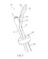
- FIG. 1illustrates an embodiment of a combined imaging/HIFU probe having an inflatable cuff extending around the shaft of the probe.
- the probeincludes a fluid outlet port at the proximal end of the HIFU transducer, though in other embodiments, the outlet port may be positioned at the distal end of the HIFU transducer or at other locations.
- FIG. 2illustrates the placement of a combined imaging/HIFU probe in the vaginal cavity of a female patient with the HIFU transducer positioned at the posterior fornix and the imaging scan head close to the cervix.
- the cuffis inflated and the vaginal cavity is filled with fluid from the outlet port at the distal end of the HIFU transducer.
- FIGS. 3A and 3Billustrate alternative configurations of a HIFU transducer with a fluid outlet part having nozzle(s) placed at various locations relative to the aperture of the HIFU transducer.
- FIG. 4illustrates a combined imaging/HIFU probe that can be used, for example, with intra-abdominal or transluminal applications.
- an inflatable cuffprovides fluid blockage and a fluid outlet port is positioned at the distal end of the probe.
- FIG. 5illustrates an intra-abdominal application of image-guided HIFU therapy of a liver tumor.
- a double set of cuffsare deployed.
- the abdominal cavityis partially filled with a liquid and the remainder with a gas.
- a laparoscopemay be used to visually assist the placement of the combined imaging/HIFU probe.
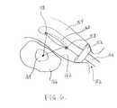
- FIG. 6illustrates a transrectal HIFU treatment of a prostate tumor.
- a cuffis deployed inside the rectum, which is filled with fluid.
- the combined imaging/HIFU probehas fluid outlet ports at both the proximal and distal ends of the HIFU transducer.
- FIG. 7Aillustrates a front view of a cover comprised of a non-permeable material that may be used to cover the aperture of a HIFU transducer.
- the coverincludes one or more perforations that allow fluid to flow through the cover.
- FIG. 7Billustrates a side section view of a HIFU transducer with a cover as illustrated in FIG. 7A .
- the HIFU transducermay be used in one or more of the combined imaging/HIFU probes described herein.
- FIG. 8illustrates a side section view of the HIFU transducer and cover as illustrated in FIG. 7B , and further encompassed by a fluid-filled sheath.
- FIGS. 9A-9Cillustrate in functional block form a HIFU transducer and imaging transducer behind a common acoustic window or behind separate acoustic windows.
- Fluidsuch as water, is used to fill the space between the transducers and the acoustic window(s) as well as filling the space outside the acoustic window(s) in the body cavity.
- a combined imaging/HIFU probe as described hereinis deployed in a body cavity that is partially or fully filled with a fluid, such as but not limited to, water or normal saline.
- a fluidsuch as but not limited to, water or normal saline.
- the fluidis used as a universal coupling medium between both an ultrasound imaging scan head and HIFU transducer of the combined probe and the tissue to be treated by the probe.
- FIG. 1illustrates an embodiment of a combined imaging/HIFU probe 10 for providing image-guided HIFU treatment of a pathology in a patient.
- a fluidsuch as water, having acoustic transmission characteristics similar to that of tissue, can be used to fill the gap between the combined probe 10 (including both the imaging scan head 12 and the HIFU transducer 16 ) and the cervix and vaginal fornices of the patient to provide the necessary coupling.
- the fluidcan fill any space of non-contact of the probe and tissue to provide optimal transmission of ultrasound energy for both imaging and therapy.
- the ultrasound imaging headdoes not need to be engaged firmly against the cervix or the fornices to obtain an optimal image of the pelvic structures.
- the fluid media in the vaginal cavityeffectively communicates the ultrasound energy to the tissue to obtain images of the pelvis, even if the scan head is positioned away from the cervix or fornices, such as in the location of upper mid portion of the vaginal canal.
- the combined imaging/HIFU probe 10 depicted in FIG. 1is configured for insertion into a body cavity of a patient.
- the combined probe 10includes an imaging scan head 12 for imaging target tissue in the patient.
- the imaging scan head 12is shown located at or near a distal end of an imaging probe shaft 14 .
- the proximal end of the imaging probe shaft 14may extend outward from the body cavity of the patient to allow a physician to manipulate the position of the imaging scan head 12 within the body cavity.
- the combined probe 10further includes a HIFU transducer 16 having an aperture through with HIFU energy is transmitted to the target tissue in the patient.
- the HIFU transducer 16is shown located at or near a distal end of a HIFU probe shaft 18 that is shown generally coupled to the imaging probe shaft 14 .
- the distal end of the HIFU probe shaft 18projects away at an angle from the main axis of the imaging probe shaft 14 . In this manner, the HIFU transducer 16 is spaced apart from the imaging scan head 12 .
- the HIFU probe shaft 18may include passages for electrical communication of signals from a signal source to the HIFU transducer 16 to enable the transducer 16 to produce appropriate pulses of HIFU energy for treatment of the patient.
- the imaging probe shaft 14may include passages for electrical communication between the imaging scan head 12 and external electronics that can receive imaging signals from the scan head 12 and produce images of the tissue being treated.
- the combined imaging/HIFU probe 10further includes an outlet port 20 that is configured to direct a flow of fluid across at least a portion of the aperture of the HIFU transducer 16 .
- This flow of fluidhelps prevent the transducer 16 and adjacent tissue of the patient from overheating when HIFU energy is being transmitted by the transducer 16 .
- the outlet port 20is positioned at a proximal end of the HIFU transducer 16 .
- Within the HIFU probe shaft 18is a channel 22 in fluid communication with the outlet port 20 for delivering a flow of fluid to the outlet port 20 .
- the probe 10is further constructed to direct at least a portion of the fluid flow from the outlet port 20 toward an area of tissue in the body cavity near the aperture of the HIFU transducer 16 .
- This fluid flowis configured to flush the area of tissue near the aperture of the HIFU transducer 16 to reduce obstructions to the transmission of HIFU energy to the target tissue.
- fluid flowing from the outlet port 20facilitates removal of bubbles, mucous, or other debris or material that may otherwise dissipate the HIFU energy being transmitted from the HIFU transducer 16 to the target tissue.
- a water pillow 28that extends across the aperture of the HIFU transducer 16 .
- the water pillow 28can further assist in cooling the HIFU transducer 16 and adjacent tissue.
- fluidsmay be circulated in and out of the water pillow 28 via channels defined in the HIFU probe shaft 18 that are not shown in FIG. 1 .
- the water pillow 28may assist with coupling the HIFU energy from the transducer 16 to the target tissue in the patient.
- the probe 10is constructed to allow fluid flowing from the outlet port 20 to fill at least a portion of the body cavity of the patient with fluid in which the imaging scan head 12 and the HIFU transducer 16 are immersed.
- the fluid in the body cavityprovides a global coupling for transmission of ultrasound energy between the combined imaging/HIFU probe and the patient.
- waterhas acoustic characteristics that are similar to tissue and can communicate the HIFU energy in continuum from the HIFU transducer 16 to the HIFU focus 50 at the target tissue, as illustrated in FIG. 2 .
- the HIFU transducer 16thus need not be in direct contact with the tissue and additional coupling gels are not required.
- Using a fluid filled body cavityallows a variable placement of the HIFU transducer 16 in terms of angle of engagement and distance from tissue contact. This freedom of engagement broadens the targeting capacity of the HIFU transducer 16 since the HIFU transducer can be freely moved to change the location of the focus 50 .
- the non-contact engagement method as disclosed hereinallows for manipulation of bodily structures, such as the cervix and uterus, to achieve a better and safer targeting path.
- This methodalso allows a variability in the shape and size of the HIFU transducer 16 since it is not necessary to match the anatomical contour of the cervix and vaginal fornices and achieve direct tissue contact for effective HIFU energy transmission.
- this methodallows flexibility of the shape and tension of the cooling water pillow 28 (shown in FIG. 1 ) covering the HIFU transducer 16 , again due to the absence of a requirement for direct contact of the water pillow 28 to the cervix and vaginal fornices.
- fluid from the outlet port 20may be used to flush the area of tissue in the body cavity near the HIFU transducer 16 .
- the combined probe 10may further be constructed to direct at least some of the fluid flow from the outlet port 20 to flush an area of tissue in the body cavity near the imaging scan head 12 .
- FIG. 2illustrates an alternative embodiment of a combined imaging/HIFU probe 10 ′ having multiple outlet ports.
- a first outlet port 30is positioned at a distal end of the HIFU aperture 16 and is configured to direct fluid flow across at least a portion of the aperture of the HIFU transducer 16 .
- the outlet port 30also directs fluid toward an area of tissue in the body cavity near the aperture of the HIFU transducer 16 to flush the area of tissue of obstructions to the transmission of HIFU energy.
- the combined imaging/HIFU probe 10 ′further comprises a second outlet port 32 that is positioned proximate to the imaging scan head 12 to direct a flow of fluid across at least a portion of the imaging scan head 12 . Additionally, the probe 10 ′ is constructed to direct at least a portion of the fluid flow from the second outlet port 32 to flush an area of tissue in the body cavity near the imaging scan head 12 .
- the flushing action of the fluid from the second outlet port 32helps reduce or remove any obstructions to the transmission of ultrasound energy between the imaging scan head 12 and the patient. By reducing obstructions near the imaging scan head 12 , clearer images of the tissue being treated may be obtained.
- the flow of fluid from the outlet ports 20 , 30 , 32may be intermittent or continuous, as desired.
- a continuous flow of fluid from one or more of the outlet portsmay be beneficial in maintaining cool temperatures of nearby tissue, especially tissue proximate to the HIFU transducer 16 , as well as flushing obstructions that may develop at or near the HIFU transducer 16 or the imaging scan head 12 .
- the channel 22 that delivers fluid to the outlet port 20may receive a flow of fluid from a receptacle that uses gravity to deliver the fluid to the channel 22 .
- An IV bag filled with fluidmay be elevated relative to the body cavity of the patient and deliver fluid under pressure of gravity to the outlet ports 20 , 30 , 32 . In such embodiments, expensive fluid pumps are not necessary to provide pressure to the fluid being delivered to the outlet ports 20 , 30 , 32 .
- an IV bag or other receptacle positioned lower relative to the body cavitymay be used to provide a negative pressure to draw fluid out of the body cavity.
- the combined imaging/HIFU probe 10 ′ shown in FIG. 2has been deployed in the vaginal cavity 40 of a female patient. More specifically, the probe 10 ′ has been inserted through the vaginal canal of the patient with the HIFU transducer 16 placed at the posterior end of the vaginal fornix 42 . The imaging scan head 12 is placed close to the cervix 44 .
- the combined imaging/HIFU probe 10 ′is being used to treat a uterine fibroid 46 located in the myometrium 48 of the uterus. Depicted by lines illustrating a conical shape, HIFU energy transmitted by the transducer 16 is directed toward a focus 50 within the uterine fibroid 46 .
- the HIFU focus 50is moved through the uterine fibroid 46 during treatment to destroy the fibroid tissue.
- Fluid flowing from one or both of the outlet ports 30 and 32is used to fill at least a portion of the vaginal cavity 40 with fluid 52 .
- the imaging scan head 12 and the HIFU transducer 16are immersed in this fluid 52 .
- the fluid 52may further flow into the endometrial cavity 54 , thus filling the uterus with fluid as well.
- Filling the endometrial cavity 54 with fluid 52may be desirable in that the fluid may assist with coupling HIFU energy transmitted from the HIFU transducer 16 to the focus 50 within the uterine fibroid 46 .
- a cuff 60that extends around the probe.
- the cuff 60is configured to obstruct an opening to the body cavity to help retain fluid in the body cavity.
- the cuff 60obstructs the opening of the vaginal canal and helps retain fluid 52 from the outlet ports 30 and/or 32 in the vaginal cavity 40 .
- a passage for air to escape from the body cavitymay be provided, especially during the time in which the body cavity is being filled with fluid. This passage may also be used to regulate the pressure of the fluid 52 in the body cavity by allowing a portion of the fluid in the body cavity to flow out past the cuff 60 .
- the cuff 60can be of any size, shape, or construction. Preferably, the cuff 60 is tailored to the anatomy of the patient to retain fluid in the particular body cavity. In use, the cuff 60 may be positioned at any location along the shaft of the probe as needed to address the particular shape and position of the opening to the body cavity to retain the fluid in the body cavity.
- An outer surface of the cuff 60preferably provides a sealing engagement with the opening to the body cavity and an inner surface of the cuff 60 preferably seals against the shaft of the probe.
- the inner surface of the cuff 60may be constructed with a flexible material that permits the probe to pivot and/or translate within the cuff while maintaining a seal against the shaft of the probe. For example, with respect to the probe 10 ′ shown in FIG.
- the shaft of the probe 10 ′may translate within (i.e., slide in and out of) the vaginal cavity 40 along the main axis of the probe through the interior surface of the cuff 60 .
- the probe 10 ′may also rotate circumferentially within the interior surface of the cuff 60 and also pivot in multiple directions at the level of the cuff to allow proper positioning of the HIFU aperture 16 and the imaging scan head 12 within the patient.
- the freedom of movement of the probe 10 ′ through the cuff 60may be achieved by using a pliable material, such as latex, polyurethane, or other suitable material, to form a ring around the shaft of the probe 10 ′.
- the flexibility of this pliable materialallows for movement of the probe, yet is able to prevent fluid leakage along the shaft of the probe.
- the cuff 60may be constructed to expand to a desired size that matches the anatomical features of the body cavity opening. While various forms of the cuff 60 can be constructed using mechanical elements to expand the cuff, the cuff 60 depicted in FIGS. 1 and 2 is constructed to be inflatable. A fluid line 62 to the cuff 60 may be incorporated in or along the HIFU probe shaft 18 or the imaging probe shaft 14 to inflate the cuff 60 using a gas or liquid fluid medium. The amount of inflation of the cuff 60 can be varied to suit the need for occlusion of the orifice to retain fluid in the body cavity. Moreover, the inflation can be adapted to allow the sliding of the probe through the cuff as well as rotation and pivoting of the probe within the cuff to allow the position of the probe to be manipulated within the body cavity for imaging and HIFU treatment.
- the combined imaging/HIFU probe 10 ′ shown in FIG. 2further includes an inlet port 66 in fluid connection with a channel 68 that is configured to convey fluid 52 out of the body cavity 40 .
- the inlet port 66 and channel 68are shown connected to the probe shaft 14 and passing through the interior of the cuff 60 .
- an inlet portsuch as the inlet port 66 may be placed anywhere with respect to the probe and/or the cuff, provided the inlet port 66 has access to the fluid 52 in the body cavity.
- the fluid filling the body cavityhas a fluid pressure that bears against the sides of the body cavity as well as the tissue structures within the body cavity.
- the pressure of the fluid in the body cavitymay be capable of distending the tissue in the body cavity.
- FIG. 2considering the situation in which fluid 52 passes through the cervix 44 into the endometrial cavity 54 , the pressure of the fluid in the endometrial cavity 54 may cause the cavity 54 to expand against the myometrium 48 , thus moving the myometrium (including the fibroid 46 ) from one position to another.
- the HIFU transducer 16transmits HIFU energy to a focus 50 within the fibroid 46 .
- the position of the target tissue in the fibroid 46may be modified relative to the focus 50 of the HIFU energy. Accordingly, it is possible to position the target tissue in the fibroid 46 relative to the focus 50 by modifying the fluid pressure in the endometrial cavity 54 without moving the position of the HIFU transducer 16 .
- a combined imaging/HIFU probesuch as the probe 10 ′ may be provided with a regulator 64 that is configured to regulate the fluid flow with respect to the body cavity.
- the regulator 64may be coupled to the channel 68 through which fluid 52 flows out of the body cavity 40 .
- the regulator 64which may be a valve, for example, is adjusted to regulate the amount of fluid 52 flowing out of the body cavity.
- the pressure of the fluid 52 in the body cavitywill tend to increase.
- the pressure of the fluid 52 in the body cavitymay decrease if a greater amount of fluid is allowed to flow out of the body cavity than is flowing into the body cavity. Accordingly, a desired pressure of the fluid in the body cavity may be obtained.
- a physician operating the probe 10 ′may observe the movement of tissue relative to a focus 50 of the HIFU energy being transmitted by the probe, and regulate the fluid pressure in the body cavity to cause tissue structures such as the fibroid 46 to move relative to the focus 50 without moving the position of the HIFU transducer 16 .
- the imaging scan head 12 and HIFU transducercan be held stationary, such as against the posterior vaginal wall, and at the same time the cervix and uterus can be moved relative to the HIFU transducer 16 by changing the vaginal volume as distended by the infused fluid 52 .
- the vaginal fluid volumeincreases, the cervix and uterus gradually move away from the stationary HIFU transducer. Deflating the fluid volume of the vaginal cavity 40 will do the opposite.
- This relative movement of the uterus with respect to the HIFU transducer 16will allow the HIFU focus 50 to move within the uterine tissue without moving the transducer 16 .
- the rate of movementcan be finely controlled by the fluid inflow or outflow at varying rates.
- the HIFU transducer 16can be systematically moved back against the fixed vaginal wall to different positions to control the other two axis of the HIFU focus.
- the ability to brace the combined imaging/HIFU probe against the fixed vaginal wallcan allow the clinician more control in handling the probe in a steady way.
- a mechanical armcan be used to hold the probe steady in a location in the vagina and then use the fluid volume to move the HIFU focus 50 as described above.
- a separate structuresuch as a valve may not be necessary in order to implement the regulator 64 .
- the fluid flowing out of the body cavity through the channel 68may be regulated by using the inflatable cuff 60 to selectively compress the size of the channel 68 within the cuff 60 .
- the regulator 64may be constricted to adjust the amount of fluid flowing into the body cavity through the outlet port(s). For example, referring to FIG.
- the regulator 64may be coupled to the channel 22 to selectively adjust the amount of fluid flowing to the outlet port 20 .
- the cuff 60may be constructed such that selective adjustment of the inflation of the cuff 60 using the cuff inlet 62 may be used to selectively constrict the channel 22 and, thus, selectively adjust the amount of fluid being delivered to the outlet port 20 according to a desired fluid pressure in the body cavity.
- the regulator 64may be considered incorporated into the cuff 60 .
- the range of target tissue to be treated by the HIFU energymay be directed through the focus 50 without moving the position of the HIFU transducer 16 .
- the cuff 60is configured to adjust the fluid flow out of the body cavity throughout the transmission of HIFU energy and thereby direct the range of target tissue to be treated by the HIFU energy.
- Outlet portssuch as the outlet ports 20 , 30 , 32 of the combined imaging/HIFU probes described herein, may assume various forms and configurations as desired.
- the outlet port 30may be comprised of a nozzle that directs a flow of fluid 70 from the outlet port 30 across at least a portion of the aperture of the HIFU transducer 16 .
- the nozzlemay direct a flow of fluid 72 in a single fluid path toward an area of tissue near the aperture of the HIFU transducer 16 to flush the area of tissue of obstructions, as previously described herein.
- FIG. 3Aillustrates another embodiment of a HIFU transducer 80 that may be used with the combined imaging/HIFU probe described herein.
- the HIFU transducer 80has an outlet port 82 from which fluid may flow.
- the outlet port 82extends around the aperture 84 of the HIFU transducer 80 and directs the fluid flow 86 in a cylindrical- or conical-shaped fluid path.
- the fluid flow 86may act to flush the area of tissue as well as flow across at least a portion of the aperture 84 to keep the tissue and the HIFU aperture at an acceptable temperature.
- the fluid flow 86is depicted by a series of dotted lines. However, it should be readily understood that the fluid flow 86 may be considered flowing in a single fluid path as fluid flows uniformly outward from the outlet port 82 around the circumference of the aperture 84 .
- FIG. 3Billustrates another alternative embodiment of a HIFU transducer 90 that may be used with the combined imaging/HIFU probe described herein.
- the HIFU transducer 90has an outlet port comprised of multiple nozzles 92 a - e that are spaced around aperture 94 of the HIFU transducer 90 .
- the nozzles 92 a - eare configured to direct fluid flow in multiple fluid paths 96 toward an area of tissue near the HIFU transducer 90 to be flushed.
- the nozzles 92 a - emay be configured to direct a flow of fluid 98 across at least a portion of the aperture 94 of the HIFU transducer 90 .
- the multiple nozzles 92 a - eare shown positioned in a ring around the aperture 94 . While the nozzles are shown evenly spaced, in other embodiments the nozzles may be positioned with uneven spacing with respect to the aperture 94 .
- the filling a body cavity with fluid for global engagement and coupling of an imaging scan head 12 and HIFU transducer 16 to tissue for image-guided HIFU therapycan be applied to any cavity or space, existing or created, in a body.
- a body cavity with fluid for global engagement and coupling of an imaging scan head 12 and HIFU transducer 16 to tissue for image-guided HIFU therapycan be applied to any cavity or space, existing or created, in a body.
- the vaginal cavitywherein HIFU energy is transmitted for treatment of a uterine fibroid.
- the rectal cavityfor treatment of pathologies in the prostate gland (e.g., as shown in FIG. 6 ), the uterus and adnexal structures.
- Another exampleis the colon for treatment of colonic polyps or neoplasia.
- Yet another exampleis to fill the esophagus partially or fully with fluid to treat target tissue in the mediastinum such as tumors or nerves, or even target tissue in the heart for ablation purposes. Still another example is to flood the stomach with a fluid to treat stomach neoplasm using HIFU.
- Yet another exampleis to fill the abdominal cavity to treat the liver (e.g., as shown in FIG. 5 ), pancreas, kidney, bowel, uterus, adnexal organs and other intra-abdominal organ targets.
- Pathologies to be treatedcan be tumors, blood vessels, and nerves and other pathologies.
- imaging/HIFU probescan be inserted into cavities and spaces including those cavities and spaces mentioned above and flooded with a fluid to perform image-guided HIFU therapy as described herein. Again, a benefit of this global engagement and coupling method allows a flexible form factor design for both the imaging and HIFU heads.
- FIG. 4depicts a probe 100 having a combined head for imaging and HIFU therapy.
- the probe 100includes a shaft 102 to which a HIFU transducer 104 is connected.
- the HIFU transducer 104includes an aperture 106 from which HIFU energy is transmitted to target tissue in the patient.
- an imaging scan head 108shown positioned at a distal end of the HIFU transducer 104 .
- the imaging scan head 108is used to image the tissue being treated.
- the combined imaging scan head 108 and HIFU transducer 104is connected to the probe shaft 102 via a hinge 110 .
- the hinge 110provides a point of articulation around which the combined head can be rotated to optimize the imaging and therapy delivery.
- a cuff 114that extends around the shaft 102 of the probe 100 .
- the cuff 114may be inflated to a desired size using a fluid flowing through an inlet 116 to the cuff 114 .
- the cuff 114is used to occlude an opening to the body cavity into which the probe is inserted and to retain fluid in the body cavity at a desired pressure.
- An advantage of using a probe with a combined imaging scan head and HIFU transducer as shown in FIG. 4is that such a probe can be inserted into areas of the body that may otherwise be poorly visualized by other means.
- a physiciancan manipulate a combined probe 100 through a small abdominal incision into a fluid filled upper abdomen (with patient in the Trendelenburg position, for example) to place the probe 100 against the surface of an organ, such as the liver, e.g., as illustrated in FIG. 5 .
- the physiciancan then use ultrasound images obtained from the imaging scan head to guide the transmission of HIFU energy from the probe to treat tumors, blood vessels, bile ducts or other targets.
- Using a combined imaging/HIFU probe in this mannerhelps alleviate the concern of inadequate visual imaging through a laparoscope, for example, due to anatomical position or obstructed background (such as by blood) in the fluid.
- the first exampleinvolves inserting a combined imaging/HIFU probe 10 ′ into the vaginal cavity 40 of a patient in the Trendelenburg position and filling the vaginal cavity with fluid 52 .
- the probe 10 ′includes one or more fluid outlet ports.
- a first outlet port 30is located at a distal end of the HIFU transducer 16
- a second outlet port 32is located adjacent to the imaging scan head 122 .
- An inflatable cuff 60that extends around the shaft of the combined probe 10 ′ is expanded just internal to the vaginal introitus to retain the fluid 52 within the vaginal cavity 40 .
- the cuff 60can, but need not be, tightly fitted to the walls of the vaginal canal.
- the fluid flow rate into or out of the vaginal cavity 40can be used to control the degree of distention of tissue in the vaginal cavity.
- the fluid 52can be retained in the vaginal cavity 40 without any spillage.
- the combined probe 10 ′can translate in and out through the cuff 60 and pivot freely in order to manipulate the placement of the probe.
- one or more sealsmay be fitted to the cuff 60 around the shaft of the probe 10 ′, preferably toward the inside of the vaginal cavity 40 , to bear against the pressure of the fluid 52 in the cavity and to help prevent unwanted seepage of fluid around the probe.
- the vaginal cavity 40can be distended by allowing fluid to flow into the cavity by gravity or by a fluid pump.
- the fluid 52can be drained out through a separate channel 68 or by using the same tubing by reversing the gravity effect or the pump direction, or by allowing fluid to simply seep past the cuff 60 .
- the imaging scan head 12can either be in contact with or away from the tissue of the cervix 44 or vaginal fornices 42 and continue to image the pelvic organs using the fluid 52 as an acoustic conduction medium.
- the fluid 52 in the vaginal cavity 40also enables HIFU energy to be transmitted from the HIFU transducer 16 through the fluid and focused at the target tissue in the uterus without the need of direct contact of the HIFU transducer 16 to the cervical/vaginal fornix tissue.
- the HIFU transducer 16can be moved in multiple directions within the fluid filled cavity 40 to move the focus 50 within the uterine tissue. Alternatively, the HIFU transducer 16 may be held stationary, such as against the vaginal wall.
- This methodprovides an effective use of image-guided HIFU therapy to treat a uterine pathology, such as fibroids.
- a small incisionis made through the anterior abdominal wall 120 , as shown in FIG. 5 , with the option of doing so under visualization of a laparoscope 122 .
- a combined imaging/HIFU probe 124is then inserted directly through the abdominal incision, possibly through a cuffed conduit.
- the cuffs 126 a and 126 bwhich extend around the probe shaft are inflated to seal off the incision.
- the shaft of the probe 124can slide in and out and pivot through the cuffs.
- Fluid 128is fed into the abdominal cavity through tubing within or along the side of the probe 124 to an outlet port 130 near the HIFU transducer 132 .
- the abdominal cavityis filled with the fluid 128 , such as normal saline, aided by the patient being in the Trendelenburg position.
- the combined probe 124is then guided towards the liver 134 , in this example, by feel or by laparoscopic visualization, and then eventually by ultrasound imaging using the imaging scan head 136 of the probe 124 .
- image-guided HIFU treatment of an intra-hepatic lesion 138can be performed.
- the focus 140 of the HIFU energyis moved throughout the liver tumor 138 to cause necrosis of the target tissue, either by moving the HIFU transducer 132 or by moving the tumor 138 by distending surrounding tissue according to pressure of the fluid 128 in the abdominal cavity.
- the physicianensures the absence of any bowel loop 142 or other obstructions or air bubbles at the interface between the imaging scan head 136 , the HIFU transducer 132 , and the liver 134 . Flushing of the tissue at the interface may be accomplished using fluid from the outlet port 130 in a manner as previously described.
- a gas fluidmay also be introduced into the body cavity, particularly to influence the pressure of the liquid fluid in the body cavity to distend the tissues in the body cavity.
- the abdominal cavityis partially filled with a liquid fluid 128 up to a fluid level 144 .
- the remaining portion of the abdominal cavityis filled with a gas 146 , such as carbon dioxide.
- the fluid pressure in the abdominal cavitycan thus be adjusted by regulating the amount of gas 146 or liquid fluid 128 in the abdominal cavity.
- a combined imaging/HIFU probe 150is inserted through the anus 152 into the rectum 154 , as illustrated in FIG. 6 .
- a cuff 156 around the probe 150may be inflated to fit against the rectal wall.
- the probe 150can slide in and out and pivot freely through the cuff 156 .
- the rectum 154is filled with fluid flowing from the outlet ports 158 around the HIFU transducer 160 .
- the patientmay be in the reverse Trendelenburg position to facilitate the fluid 162 filling the rectum 154 .
- image-guided HIFU treatment of a prostate tumor 164 in the prostate gland 166for example, can be performed.
- the prostate gland 166 and the pathology 164 withincan be visualized using the imaging scan head 168 and treated with HIFU energy with a greater degree of accessibility.
- ultrasound imagingcan see beyond the surface of the target organ.
- ultrasound imagingcan see a tumor deep within liver tissue as illustrated in FIG. 5 . It can also see bleeding blood vessels deep in the liver, especially with a Doppler mode, while neither of these pathologies can be seen by laparoscopy.
- Similar examplescan be applied to cases of intramural fibroids in the uterus, deep pancreatic tumors, etc., all of which are not visible by laparoscopy but can be imaged by ultrasound, especially using the global engagement and coupling methods described herein.
- a fluid input line to the cuff 60can be incorporated in or along the sides of the shaft of the combined imaging/HIFU probe.
- One or more fluid outlets 20 , 30 , 32can be provided at the distal end proximal end, or at different positions around the HIFU transducer 16 and/or imaging scan head 12 , or elsewhere on the probe.
- the flow of fluid from the outlets 20 , 30 , 32can be directed in various directions to flush any gas bubbles or debris away from the interface between the HIFU transducer 16 and the tissue nearby.
- a fluid line with an outlet portcan be placed apart from the combined probe at a portion of the cavity, preferably the most dependent part of the cavity, to fill the cavity with the fluid.
- a fluid outlet portattached to the tip of an optical scope, such as laparoscope, or at the end of a hysteroscope or cystoscope, to be deployed in the body cavity in concert with the combined imaging/HIFU probe to visually direct the fluid flow to fill the cavity and to wash away gas bubbles and debris and double check the location of the combined probe and clearance of the HIFU path.
- an optical scopesuch as laparoscope
- a hysteroscope or cystoscopeto be deployed in the body cavity in concert with the combined imaging/HIFU probe to visually direct the fluid flow to fill the cavity and to wash away gas bubbles and debris and double check the location of the combined probe and clearance of the HIFU path.
- the fluid 52can be water or more ideally an isotonic aqueous solution such as normal saline to avoid hypotonic fluid absorption into the body.
- the fluid 52can be degassed as needed.
- the intake of the fluid 52 into the transport tubinge.g., channel 22 ) can be as simple as an IV bag with gravity flow or a fluid infusion pump.
- a combined imaging/HIFU probe as described hereinmay include a cover 180 extends over the aperture of the HIFU transducer 182 , as illustrated in FIGS. 7A and 7B .
- the cover 180is comprised of a non-permeable material and can be rigid, semi-rigid, or pliable, as desired.
- the cover 180is sealingly engaged with the HIFU transducer 182 and has at least one perforation 184 defined therethrough to allow fluid to flow through the cover.
- the HIFU transducer 182includes an outlet port 186 shown positioned between the cover 180 and the aperture of the HIFU transducer 182 .
- a first channel 188 in the shaft 190 of the probedelivers fluid to the outlet port 186 , which flows out into the space 192 between the HIFU transducer 182 and the cover 180 .
- the fluidcirculates within the space 192 under the cover 180 .
- the fluidmay then exit through the one or more perforations 184 in the cover to fill the body cavity.
- the fluids circulating in the space between the cover 180 and the HIFU transducer 184serves to cool surface of the HIFU transducer and to provide an ultrasound coupling media between the HIFU transducer 182 and adjacent tissue. If desired, the fluid can be chilled to enhance the cooling effect.
- the fluid from the outlet port 186may further be configured to flow through the one or more perforations 184 in the cover toward an area of tissue in the body cavity near the aperture of the HIFU transducer 182 .
- the fluid thus expelled through the one or more perforations 184can serve to flush away any gas bubbles, mucus, or other debris at the interface between the aperture of the HIFU transducer 182 and the adjacent tissue.
- the fluids supplied to the HIFU transducer 182can be pressurized by a gravity-fed IV bag system or by a fluid pump.
- the infusion rate and pressure of the fluid in the body cavitycan be adjusted to meet various perfusion and tissue positioning requirements.
- the HIFU transducer 182further includes an inlet port 194 positioned between the cover 180 and the HIFU transducer 182 .
- the inlet port 194is connected to a second channel 196 that conveys fluid away from the HIFU transducer 182 .
- fluid in the space 192 that does not otherwise flow out of the perforations 184 into the body cavitymay flow into the inlet port 194 and away from the body cavity.
- the flow of the fluid from the HIFU transducer 182 through the inlet port 194may be higher than the flow of fluid from the HIFU transducer 182 through the at least one perforation 184 in the cover 180 . Accordingly, the probe may provide greater circulation of fluid into and within the space 192 than otherwise flows out through the one or more perforations 184 into the body cavity.
- the fluid in the body cavitycan effectively communicate both the imaging ultrasound and the therapeutic HIFU energy from the probe without requiring direct contact with the cervical or vaginal fornix tissue, there is a greater ability to vary the physical form factors of the imaging scan head 12 and the HIFU transducer 16 .
- These form factorscan be designed to facilitate the insertion of the combined probe through various body cavity openings, such as the vaginal introitus.
- the imaging scan head 12 and the HIFU transducer 16can be inserted simultaneously or in sequence.
- the form factorscan be tailored to the anatomy of different patients and optimized for deployment of the probe within a particular body cavity.
- the freedom to vary the form factors of the combined probeallows the use of different imaging and therapeutic heads, including from off-the-shelf commercial sources.
- FIG. 8illustrates a side section view of the HIFU transducer and cover as illustrated in FIG. 7B .
- the HIFU transducer 200is covered with a cover 201 comprising a rigid, semi-rigid, or pliant membrane.
- a flexible sheath 202overlies the cover 201 and preferably is sealingly engaged to the circumference of the HIFU transducer 200 .
- Fluid flowing through a first channel 205 to an outlet port 207fills the space between the aperture of the transducer 200 and the cover 201 .
- the fluidalso fills the space between the cover 201 and the sheath 202 , causing the sheath 202 to inflate with fluid.
- One or more perforations 203 in the cover 201allows fluid to flow from the space between the transducer 200 and the cover 201 into the space between the cover 201 and the sheath 202 , or vice versa. Some or all of the fluid in the space between the transducer 200 and the cover 201 or the space between the cover 201 and the sheath 202 flows away from the transducer 200 through inlet port 208 via a second channel 204 , especially once the fluid pressure under the sheath 202 reaches an equilibrium with the fluid pressure in the space between the transducer 200 and the cover 201 .
- an acoustic coupling between the HIFU transducer 200 and adjacent tissue in the patientis obtained by inflating the flexible sheath 202 with fluid and then pressing the sheath 202 against the tissue.
- the flexible sheath 202When inflated with fluid, the flexible sheath 202 is able to conform more closely to irregular features of the tissue and thus improve the coupling of HIFU energy from the transducer 200 to the tissue.
- the sheath 202may extend along the shaft 206 of the transducer 200 to cover the shaft and help prevent communication of contamination in the body cavity.
- the cover 201can help prevent tissue or other objects from applying direct pressure to face of the transducer 200 , thereby reducing the risk of transducer damage or tissue burns. Moreover, the same cooling fluid can be circulated over the surface of the transducer 200 and within the flexible sheath 202 to cool both the HIFU transducer 200 and the tissue adjacent to the sheath. A sufficient convective heat exchange can be obtained, even at a steady-state inflation of the sheath 202 , to help maintain temperature equilibrium between the fluid within the cover 201 and any fluid outside the cover 201 .
- a physicianmay want to effectively couple HIFU energy transmitted from the transducer 200 to adjacent tissue in the patient, particularly where there the transducer 200 is used outside a cavity in the body or is used within a body cavity, but the physician or patient wants to avoid fluid coming in direct contact with the walls of the cavity.
- benefits of the global fluid coupling described hereinmay be obtained with a fluid-filled sheath configuration as illustrated in FIG. 8 . It is not necessary that the HIFU transducer 200 be directly pressed against tissue of the patient.
- the fluid-filled sheath 202is pressed against the tissue and provides a coupling for transmission of HIFU energy from the transducer 200 to the tissue to be treated.
- the sheath 202further overlies an imaging scan head of the probe.
- the sheath 202is configured to inflate with fluid around the imaging scan head to provide a coupling for transmission of ultrasound energy between the imaging scan head and the patient.
- FIG. 9Aillustrates, in functional block form, a side view of a HIFU transducer 210 and an imaging transducer or scan head 212 disposed behind a common acoustic window 214 .
- the acoustic window 214may comprise the cover 180 illustrated in FIGS. 7A and 7B .
- the imaging scan head 212may be centrally located within the HIFU transducer 210 , thus providing an advantageous form factor when fitting the acoustic window 214 to the imaging scan head 212 and transducer 210 .
- a coupling gelis placed on and around ultrasonic devices, such as the imaging scan head 212 and transducer 210 , to improve the acoustic coupling of the devices to the patient.
- ultrasonic devicessuch as the imaging scan head 212 and transducer 210
- This conventional approachmay be acceptable when the ultrasonic devices are pressed against the adjacent tissue to force bubbles out of the coupling gel.
- the global fluid coupling described in the present applicationallows an imaging scan head 212 (and HIFU transducer 210 ) to acoustically couple to nearby tissue without requiring direct contact with the tissue.
- the probe described herein and depicted in FIG. 9Auses a fluid 216 , such as water or saline, to fill the space between the imaging scan head 212 and the acoustic window 214 .
- This fluid 216may be the same as the fluid 218 filling the body cavity.
- FIG. 9Billustrates, in functional block form, another probe design with a HIFU transducer 220 and an imaging scan head 222 .
- the imaging scan head 222is located adjacent to the HIFU transducer 220 .
- the imaging scan head 222 and the HIFU transducer 220are behind a common acoustic window 228 .
- a fluid 224such as water or saline, may be used to fill the space between the imaging scan head 222 and the acoustic window 228 . This fluid 224 may be the same as the fluid 226 filling the body cavity.
- FIG. 9Cillustrates, in functional block form, a HIFU transducer 230 and an imaging scan head 234 behind separate acoustic windows 236 and 232 , respectively.
- Fluid 238 , 242such as water or saline, may be used to fill the space between the transducers and the acoustic windows 232 , 236 .
- the same or similar fluid 240may be used to fill the space outside the acoustic windows 232 , 236 in the body cavity.
- the acoustic windows 232 , 236(as well as the acoustic windows 214 and 228 in FIGS. 9A and 9B ) may have one or more perforations defined therethrough to allow fluid to flow through the acoustic windows.
Landscapes
- Health & Medical Sciences (AREA)
- Life Sciences & Earth Sciences (AREA)
- Engineering & Computer Science (AREA)
- General Health & Medical Sciences (AREA)
- Surgery (AREA)
- Nuclear Medicine, Radiotherapy & Molecular Imaging (AREA)
- Veterinary Medicine (AREA)
- Public Health (AREA)
- Physics & Mathematics (AREA)
- Biomedical Technology (AREA)
- Animal Behavior & Ethology (AREA)
- Molecular Biology (AREA)
- Medical Informatics (AREA)
- Heart & Thoracic Surgery (AREA)
- Radiology & Medical Imaging (AREA)
- Biophysics (AREA)
- Pathology (AREA)
- Acoustics & Sound (AREA)
- Mechanical Engineering (AREA)
- Orthopedic Medicine & Surgery (AREA)
- Vascular Medicine (AREA)
- Ultra Sonic Daignosis Equipment (AREA)
Abstract
Description
Claims (49)
Priority Applications (2)
| Application Number | Priority Date | Filing Date | Title |
|---|---|---|---|
| US11/831,048US8052604B2 (en) | 2007-07-31 | 2007-07-31 | Methods and apparatus for engagement and coupling of an intracavitory imaging and high intensity focused ultrasound probe |
| PCT/US2008/071607WO2009018351A1 (en) | 2007-07-31 | 2008-07-30 | Methods and apparatus for engagement and coupling of an intracavitory imaging and high intensity focused ultrasound probe |
Applications Claiming Priority (1)
| Application Number | Priority Date | Filing Date | Title |
|---|---|---|---|
| US11/831,048US8052604B2 (en) | 2007-07-31 | 2007-07-31 | Methods and apparatus for engagement and coupling of an intracavitory imaging and high intensity focused ultrasound probe |
Publications (2)
| Publication Number | Publication Date |
|---|---|
| US20090036773A1 US20090036773A1 (en) | 2009-02-05 |
| US8052604B2true US8052604B2 (en) | 2011-11-08 |
Family
ID=39790410
Family Applications (1)
| Application Number | Title | Priority Date | Filing Date |
|---|---|---|---|
| US11/831,048Expired - Fee RelatedUS8052604B2 (en) | 2007-07-31 | 2007-07-31 | Methods and apparatus for engagement and coupling of an intracavitory imaging and high intensity focused ultrasound probe |
Country Status (2)
| Country | Link |
|---|---|
| US (1) | US8052604B2 (en) |
| WO (1) | WO2009018351A1 (en) |
Cited By (18)
| Publication number | Priority date | Publication date | Assignee | Title |
|---|---|---|---|---|
| US20100228126A1 (en)* | 2009-03-06 | 2010-09-09 | Mirabilis Medica Inc. | Ultrasound treatment and imaging applicator |
| US8852103B2 (en) | 2011-10-17 | 2014-10-07 | Butterfly Network, Inc. | Transmissive imaging and related apparatus and methods |
| US9667889B2 (en) | 2013-04-03 | 2017-05-30 | Butterfly Network, Inc. | Portable electronic devices with integrated imaging capabilities |
| US9757196B2 (en) | 2011-09-28 | 2017-09-12 | Angiodynamics, Inc. | Multiple treatment zone ablation probe |
| US20170258530A1 (en)* | 2016-03-08 | 2017-09-14 | Biosense Webster (Israel) Ltd. | Magnetic resonance thermometry during ablation |
| US9888956B2 (en) | 2013-01-22 | 2018-02-13 | Angiodynamics, Inc. | Integrated pump and generator device and method of use |
| US9895189B2 (en) | 2009-06-19 | 2018-02-20 | Angiodynamics, Inc. | Methods of sterilization and treating infection using irreversible electroporation |
| US10543037B2 (en) | 2013-03-15 | 2020-01-28 | Medtronic Ardian Luxembourg S.A.R.L. | Controlled neuromodulation systems and methods of use |
| US10660691B2 (en) | 2015-10-07 | 2020-05-26 | Angiodynamics, Inc. | Multiple use subassembly with integrated fluid delivery system for use with single or dual-lumen peristaltic tubing |
| US10835215B2 (en) | 2012-09-12 | 2020-11-17 | Convergent Life Sciences, Inc. | Method and apparatus for laser ablation under ultrasound guidance |
| US11246566B2 (en)* | 2015-06-26 | 2022-02-15 | B-K Medical Aps | US imaging probe with an instrument channel |
| US11707629B2 (en) | 2009-05-28 | 2023-07-25 | Angiodynamics, Inc. | System and method for synchronizing energy delivery to the cardiac rhythm |
| US11723710B2 (en) | 2016-11-17 | 2023-08-15 | Angiodynamics, Inc. | Techniques for irreversible electroporation using a single-pole tine-style internal device communicating with an external surface electrode |
| US11931096B2 (en) | 2010-10-13 | 2024-03-19 | Angiodynamics, Inc. | System and method for electrically ablating tissue of a patient |
| US12102376B2 (en) | 2012-02-08 | 2024-10-01 | Angiodynamics, Inc. | System and method for increasing a target zone for electrical ablation |
| US12114911B2 (en) | 2014-08-28 | 2024-10-15 | Angiodynamics, Inc. | System and method for ablating a tissue site by electroporation with real-time pulse monitoring |
| US12201349B2 (en) | 2009-04-03 | 2025-01-21 | Angiodynamics, Inc. | Congestive obstruction pulmonary disease (COPD) |
| USD1084316S1 (en) | 2023-11-20 | 2025-07-15 | Angiodynamics, Inc. | Ferrule |
Families Citing this family (32)
| Publication number | Priority date | Publication date | Assignee | Title |
|---|---|---|---|---|
| US10219815B2 (en) | 2005-09-22 | 2019-03-05 | The Regents Of The University Of Michigan | Histotripsy for thrombolysis |
| WO2010111233A2 (en)* | 2009-03-23 | 2010-09-30 | Medicis Technologies Corporation | Analysis of real time backscatter data for fault signal generation in a medical hifu device |
| US8932238B2 (en)* | 2009-09-29 | 2015-01-13 | Liposonix, Inc. | Medical ultrasound device with liquid dispensing device coupled to a therapy head |
| GB2474233A (en) | 2009-10-06 | 2011-04-13 | Uk Investments Associates Llc | Cooling pump comprising a detachable head portion |
| US8986231B2 (en) | 2009-10-12 | 2015-03-24 | Kona Medical, Inc. | Energetic modulation of nerves |
| US8986211B2 (en) | 2009-10-12 | 2015-03-24 | Kona Medical, Inc. | Energetic modulation of nerves |
| US9119951B2 (en) | 2009-10-12 | 2015-09-01 | Kona Medical, Inc. | Energetic modulation of nerves |
| US8469904B2 (en) | 2009-10-12 | 2013-06-25 | Kona Medical, Inc. | Energetic modulation of nerves |
| US20110092880A1 (en) | 2009-10-12 | 2011-04-21 | Michael Gertner | Energetic modulation of nerves |
| EP2488250B1 (en)* | 2009-10-12 | 2015-11-25 | Kona Medical, Inc. | Energetic modulation of nerves |
| US20110118600A1 (en) | 2009-11-16 | 2011-05-19 | Michael Gertner | External Autonomic Modulation |
| US8295912B2 (en) | 2009-10-12 | 2012-10-23 | Kona Medical, Inc. | Method and system to inhibit a function of a nerve traveling with an artery |
| US9174065B2 (en) | 2009-10-12 | 2015-11-03 | Kona Medical, Inc. | Energetic modulation of nerves |
| US20160059044A1 (en) | 2009-10-12 | 2016-03-03 | Kona Medical, Inc. | Energy delivery to intraparenchymal regions of the kidney to treat hypertension |
| US11998266B2 (en) | 2009-10-12 | 2024-06-04 | Otsuka Medical Devices Co., Ltd | Intravascular energy delivery |
| US8876740B2 (en)* | 2010-04-12 | 2014-11-04 | University Of Washington | Methods and systems for non-invasive treatment of tissue using high intensity focused ultrasound therapy |
| KR20130015146A (en)* | 2011-08-02 | 2013-02-13 | 삼성전자주식회사 | Method and apparatus for processing medical image, robotic surgery system using image guidance |
| BR112015026039A8 (en) | 2013-04-18 | 2018-02-06 | Koninklijke Philips Nv | HEAT TREATMENT SYSTEM GUIDED BY MAGNETIC RESONANCE AND METHOD FOR DETERMINING THE END OF A COOLING PERIOD IN A HEAT TREATMENT PROCESS |
| US10780298B2 (en) | 2013-08-22 | 2020-09-22 | The Regents Of The University Of Michigan | Histotripsy using very short monopolar ultrasound pulses |
| US10925579B2 (en) | 2014-11-05 | 2021-02-23 | Otsuka Medical Devices Co., Ltd. | Systems and methods for real-time tracking of a target tissue using imaging before and during therapy delivery |
| JP6979882B2 (en) | 2015-06-24 | 2021-12-15 | ザ リージェンツ オブ ザ ユニヴァシティ オブ ミシガン | Tissue disruption therapy systems and methods for the treatment of brain tissue |
| US20170319235A1 (en)* | 2016-05-06 | 2017-11-09 | Amphora Medical, Inc. | Bladder treatment methods and devices |
| WO2017211754A1 (en)* | 2016-06-09 | 2017-12-14 | Koninklijke Philips N.V. | Coolable ultrasound probe |
| EP3471620B1 (en) | 2016-06-17 | 2020-09-16 | Koninklijke Philips N.V. | Ultrasonic head comprising a pliable cover with a regular pattern of apertures |
| CN107485414B (en)* | 2017-08-17 | 2021-02-19 | 中国人民解放军第三军医大学第一附属医院 | Ultrasonic combined probe for use in blood vessel |
| AU2019389001B2 (en) | 2018-11-28 | 2025-08-14 | Histosonics, Inc. | Histotripsy systems and methods |
| KR20220024497A (en)* | 2019-06-19 | 2022-03-03 | 테라끌리옹 에스에이 | Method and device for treating varicose veins by application of high-intensity focused ultrasound |
| US20220401071A1 (en)* | 2020-01-07 | 2022-12-22 | Covidien Lp | Devices, systems, and methods for trans-vaginal, ultrasound-guided hysteroscopic surgical procedures |
| US11813485B2 (en) | 2020-01-28 | 2023-11-14 | The Regents Of The University Of Michigan | Systems and methods for histotripsy immunosensitization |
| EP4114520A4 (en)* | 2020-03-06 | 2024-02-14 | Histosonics, Inc. | Minimally invasive histotripsy systems and methods |
| JP2023540482A (en) | 2020-08-27 | 2023-09-25 | ザ リージェンツ オブ ザ ユニバーシティー オブ ミシガン | Ultrasonic transducer with transmitting and receiving functions for histotripsy |
| EP4608504A1 (en) | 2022-10-28 | 2025-09-03 | Histosonics, Inc. | Histotripsy systems and methods |
Citations (108)
| Publication number | Priority date | Publication date | Assignee | Title |
|---|---|---|---|---|
| US3470868A (en) | 1964-06-06 | 1969-10-07 | Siemens Ag | Ultrasound diagnostic apparatus |
| US3480002A (en) | 1967-01-24 | 1969-11-25 | Magnaflux Corp | Medical ultrasonic scanning system |
| US3676584A (en) | 1970-07-13 | 1972-07-11 | Chris J Plakas | Echo coincidence ultrasonic scanning |
| US3941112A (en) | 1973-06-22 | 1976-03-02 | Ducellier Et Cie | Ignition device for internal combustion engines |
| US4059098A (en) | 1975-07-21 | 1977-11-22 | Stanford Research Institute | Flexible ultrasound coupling system |
| US4097835A (en) | 1976-09-20 | 1978-06-27 | Sri International | Dual transducer arrangement for ultrasonic imaging system |
| US4185502A (en) | 1977-10-11 | 1980-01-29 | Ralph Frank | Transducer coupling apparatus |
| US4282755A (en) | 1979-12-05 | 1981-08-11 | Technicare Corporation | Transducer drive and control |
| US4347850A (en) | 1980-03-19 | 1982-09-07 | Indianapolis Center For Advanced Research, Inc. | Direct water coupling device for ultrasound breast scanning in a supine position |
| US4484569A (en) | 1981-03-13 | 1984-11-27 | Riverside Research Institute | Ultrasonic diagnostic and therapeutic transducer assembly and method for using |
| US4742829A (en) | 1986-08-11 | 1988-05-10 | General Electric Company | Intracavitary ultrasound and biopsy probe for transvaginal imaging |
| US4756313A (en)* | 1986-11-05 | 1988-07-12 | Advanced Diagnostic Medical Systems, Inc. | Ultrasonic probe |
| US4835689A (en) | 1987-09-21 | 1989-05-30 | General Electric Company | Adaptive coherent energy beam formation using phase conjugation |
| US4858613A (en) | 1988-03-02 | 1989-08-22 | Laboratory Equipment, Corp. | Localization and therapy system for treatment of spatially oriented focal disease |
| US4865042A (en) | 1985-08-16 | 1989-09-12 | Hitachi, Ltd. | Ultrasonic irradiation system |
| US4893624A (en) | 1988-06-21 | 1990-01-16 | Massachusetts Institute Of Technology | Diffuse focus ultrasound hyperthermia system |
| US5005579A (en) | 1987-02-17 | 1991-04-09 | Richard Wolf Gmbh | Apparatus for spatial location and destruction of objects inside the body by means of ultrasound |
| US5036855A (en) | 1988-03-02 | 1991-08-06 | Laboratory Equipment, Corp. | Localization and therapy system for treatment of spatially oriented focal disease |
| US5080102A (en) | 1983-12-14 | 1992-01-14 | Edap International, S.A. | Examining, localizing and treatment with ultrasound |
| US5080660A (en) | 1990-05-11 | 1992-01-14 | Applied Urology, Inc. | Electrosurgical electrode |
| US5117832A (en) | 1990-09-21 | 1992-06-02 | Diasonics, Inc. | Curved rectangular/elliptical transducer |
| JPH0523336A (en)* | 1991-07-19 | 1993-02-02 | Fujitsu Ltd | Ultrasonic probe |
| US5234429A (en) | 1992-07-06 | 1993-08-10 | Goldhaber Neil G | Cauterization instrument and associated surgical method |
| EP0301360B1 (en) | 1987-07-31 | 1993-11-18 | Siemens Aktiengesellschaft | Shock wave apparatus with a central ultrasonic location system |
| US5271402A (en)* | 1992-06-02 | 1993-12-21 | Hewlett-Packard Company | Turbine drive mechanism for steering ultrasound signals |
| EP0614651A1 (en) | 1993-03-10 | 1994-09-14 | Kabushiki Kaisha Toshiba | Ultrasonic wave medical treatment apparatus suitable for use under guidance of magnetic resonance imaging |
| WO1994027502A1 (en)* | 1993-05-25 | 1994-12-08 | Boston Scientific Corporation | Medical acoustic imaging catheter and guidewire |
| US5391140A (en) | 1993-01-29 | 1995-02-21 | Siemens Aktiengesellschaft | Therapy apparatus for locating and treating a zone in the body of a life form with acoustic waves |
| US5441499A (en) | 1993-07-14 | 1995-08-15 | Dekna Elektro-U. Medizinische Apparatebau Gesellschaft Mbh | Bipolar radio-frequency surgical instrument |
| US5471988A (en) | 1993-12-24 | 1995-12-05 | Olympus Optical Co., Ltd. | Ultrasonic diagnosis and therapy system in which focusing point of therapeutic ultrasonic wave is locked at predetermined position within observation ultrasonic scanning range |
| US5474071A (en) | 1991-03-05 | 1995-12-12 | Technomed Medical Systems | Therapeutic endo-rectal probe and apparatus constituting an application thereof for destroying cancer tissue, in particular of the prostate, and preferably in combination with an imaging endo-cavitary-probe |
| US5492126A (en) | 1994-05-02 | 1996-02-20 | Focal Surgery | Probe for medical imaging and therapy using ultrasound |
| US5520188A (en) | 1994-11-02 | 1996-05-28 | Focus Surgery Inc. | Annular array transducer |
| US5558092A (en) | 1995-06-06 | 1996-09-24 | Imarx Pharmaceutical Corp. | Methods and apparatus for performing diagnostic and therapeutic ultrasound simultaneously |
| EP0734742A2 (en) | 1995-03-31 | 1996-10-02 | Kabushiki Kaisha Toshiba | Ultrasound therapeutic apparatus |
| US5619999A (en) | 1995-12-28 | 1997-04-15 | Siemens Medical Systems, Inc. | Body surface position locator for ultrasound transducer |
| US5720287A (en) | 1993-07-26 | 1998-02-24 | Technomed Medical Systems | Therapy and imaging probe and therapeutic treatment apparatus utilizing it |
| US5762066A (en) | 1992-02-21 | 1998-06-09 | Ths International, Inc. | Multifaceted ultrasound transducer probe system and methods for its use |
| US5769790A (en) | 1996-10-25 | 1998-06-23 | General Electric Company | Focused ultrasound surgery system guided by ultrasound imaging |
| US5810007A (en) | 1995-07-26 | 1998-09-22 | Associates Of The Joint Center For Radiation Therapy, Inc. | Ultrasound localization and image fusion for the treatment of prostate cancer |
| US5882302A (en) | 1992-02-21 | 1999-03-16 | Ths International, Inc. | Methods and devices for providing acoustic hemostasis |
| US5976092A (en) | 1998-06-15 | 1999-11-02 | Chinn; Douglas O. | Combination stereotactic surgical guide and ultrasonic probe |
| US6002251A (en) | 1995-12-15 | 1999-12-14 | Sun; Yu-Shi | Electromagnetic-field-focusing remote-field eddy-current probe system and method for inspecting anomalies in conducting plates |
| US6007499A (en) | 1997-10-31 | 1999-12-28 | University Of Washington | Method and apparatus for medical procedures using high-intensity focused ultrasound |
| US6042556A (en) | 1998-09-04 | 2000-03-28 | University Of Washington | Method for determining phase advancement of transducer elements in high intensity focused ultrasound |
| US6050943A (en) | 1997-10-14 | 2000-04-18 | Guided Therapy Systems, Inc. | Imaging, therapy, and temperature monitoring ultrasonic system |
| US6126607A (en)* | 1997-11-03 | 2000-10-03 | Barzell-Whitmore Maroon Bells, Inc. | Ultrasound interface control system |
| US6196972B1 (en) | 1998-11-11 | 2001-03-06 | Spentech, Inc. | Doppler ultrasound method and apparatus for monitoring blood flow |
| US6217530B1 (en) | 1999-05-14 | 2001-04-17 | University Of Washington | Ultrasonic applicator for medical applications |
| US6254601B1 (en) | 1998-12-08 | 2001-07-03 | Hysterx, Inc. | Methods for occlusion of the uterine arteries |
| US20010012934A1 (en) | 1999-02-24 | 2001-08-09 | Scimed Life Systems, Inc. | Guide wire system for RF recanalization of vascular blockages |
| US20020029036A1 (en) | 1995-06-23 | 2002-03-07 | Gyrus Medical Limited | Electrosurgical generator and system |
| US6390973B1 (en) | 1998-06-25 | 2002-05-21 | Asahi Kogaku Kogyo Kabushiki Kaisha | Endoscope for ultrasonic examination and surgical treatment associated thereto |
| US20020065512A1 (en) | 2000-07-13 | 2002-05-30 | Todd Fjield | Thermal treatment methods and apparatus with focused energy application |
| US6425867B1 (en) | 1998-09-18 | 2002-07-30 | University Of Washington | Noise-free real time ultrasonic imaging of a treatment site undergoing high intensity focused ultrasound therapy |
| US20020120259A1 (en) | 1995-06-07 | 2002-08-29 | Lettice John J. | Methods for targeted electrosurgery on contained herniated discs |
| US6451013B1 (en) | 2000-01-19 | 2002-09-17 | Medtronic Xomed, Inc. | Methods of tonsil reduction using high intensity focused ultrasound to form an ablated tissue area containing a plurality of lesions |
| US6461314B1 (en) | 1999-02-02 | 2002-10-08 | Transurgical, Inc. | Intrabody hifu applicator |
| US6488639B1 (en) | 1998-05-13 | 2002-12-03 | Technomed Medical Systems, S.A | Frequency adjustment in high intensity focused ultrasound treatment apparatus |
| US6537224B2 (en) | 2001-06-08 | 2003-03-25 | Vermon | Multi-purpose ultrasonic slotted array transducer |
| US20030060736A1 (en) | 1999-05-14 | 2003-03-27 | Martin Roy W. | Lens-focused ultrasonic applicator for medical applications |
| US6613004B1 (en) | 2000-04-21 | 2003-09-02 | Insightec-Txsonics, Ltd. | Systems and methods for creating longer necrosed volumes using a phased array focused ultrasound system |
| US6626855B1 (en) | 1999-11-26 | 2003-09-30 | Therus Corpoation | Controlled high efficiency lesion formation using high intensity ultrasound |
| US6633658B1 (en) | 2000-03-17 | 2003-10-14 | Senorx, Inc. | System and method for managing intermittent interference on imaging systems |
| US6645162B2 (en) | 2000-12-27 | 2003-11-11 | Insightec - Txsonics Ltd. | Systems and methods for ultrasound assisted lipolysis |
| US20030233045A1 (en) | 2002-05-30 | 2003-12-18 | University Of Washington | Solid hydrogel coupling for ultrasound imaging and therapy |
| US6666835B2 (en) | 1999-05-14 | 2003-12-23 | University Of Washington | Self-cooled ultrasonic applicator for medical applications |
| US6676601B1 (en) | 1999-05-26 | 2004-01-13 | Technomed Medical Systems, S.A. | Apparatus and method for location and treatment using ultrasound |
| US20040030269A1 (en) | 2000-11-07 | 2004-02-12 | Gerald Horn | Method and apparatus for the correction of presbyopia using high intensity focused ultrasound |
| US6692450B1 (en) | 2000-01-19 | 2004-02-17 | Medtronic Xomed, Inc. | Focused ultrasound ablation devices having selectively actuatable ultrasound emitting elements and methods of using the same |
| US6719694B2 (en) | 1999-12-23 | 2004-04-13 | Therus Corporation | Ultrasound transducers for imaging and therapy |
| US20040082859A1 (en) | 2002-07-01 | 2004-04-29 | Alan Schaer | Method and apparatus employing ultrasound energy to treat body sphincters |
| US6740082B2 (en) | 1998-12-29 | 2004-05-25 | John H. Shadduck | Surgical instruments for treating gastro-esophageal reflux |
| US20040153126A1 (en) | 2001-06-07 | 2004-08-05 | Takashi Okai | Method and apparatus for treating uterine myoma |
| WO2004073524A1 (en) | 2003-02-20 | 2004-09-02 | Manoa Medical, Inc. | Bendable cutting device |
| US20040242999A1 (en) | 2003-06-02 | 2004-12-02 | Shuki Vitek | Endo-cavity focused ultrasound transducer |
| US20040243201A1 (en) | 1997-09-11 | 2004-12-02 | Vnus Medical Technologies, Inc. | Method and apparatus for applying energy to biological including the use of tumescent tissue compression |
| WO2005000097A2 (en) | 2003-06-10 | 2005-01-06 | The Foundry, Inc. | Methods and apparatus for non-invasively treating atrial fibrillation using high intensity focused ultrasound |
| US6840936B2 (en) | 1996-10-22 | 2005-01-11 | Epicor Medical, Inc. | Methods and devices for ablation |
| US20050038340A1 (en) | 1998-09-18 | 2005-02-17 | University Of Washington | Use of contrast agents to increase the effectiveness of high intensity focused ultrasound therapy |
| US20050085726A1 (en) | 2003-01-14 | 2005-04-21 | Francois Lacoste | Therapy probe |
| US20050101854A1 (en) | 2003-11-10 | 2005-05-12 | Sonotech, Inc. | Medical ultrasound transducer UV sterilization device |
| US20050154431A1 (en) | 2003-12-30 | 2005-07-14 | Liposonix, Inc. | Systems and methods for the destruction of adipose tissue |
| US6936046B2 (en) | 2000-01-19 | 2005-08-30 | Medtronic, Inc. | Methods of using high intensity focused ultrasound to form an ablated tissue area containing a plurality of lesions |
| US20050203399A1 (en) | 1999-09-17 | 2005-09-15 | University Of Washington | Image guided high intensity focused ultrasound device for therapy in obstetrics and gynecology |
| US20050256405A1 (en) | 2004-05-17 | 2005-11-17 | Makin Inder Raj S | Ultrasound-based procedure for uterine medical treatment |
| US20060052701A1 (en) | 1998-09-18 | 2006-03-09 | University Of Washington | Treatment of unwanted tissue by the selective destruction of vasculature providing nutrients to the tissue |
| US7105007B2 (en) | 2002-11-21 | 2006-09-12 | Hibler Timothy B | Cervical medical device, system and method |
| WO2006097661A1 (en) | 2005-03-15 | 2006-09-21 | Edap S.A. | Therapeutic endocavity probe comprising an imaging transducer integrated within the therapy ultrasonic transducer |
| US20060264748A1 (en) | 2004-09-16 | 2006-11-23 | University Of Washington | Interference-free ultrasound imaging during HIFU therapy, using software tools |
| EP1726267A2 (en) | 2005-05-25 | 2006-11-29 | Fujinon Corporation | High frequency treatment tool |
| US7175596B2 (en) | 2001-10-29 | 2007-02-13 | Insightec-Txsonics Ltd | System and method for sensing and locating disturbances in an energy path of a focused ultrasound system |
| US20070066990A1 (en) | 2005-09-19 | 2007-03-22 | Andrew Marsella | Device for forming a fluid tight seal during a procedure within a hollow organ |
| US7258674B2 (en) | 2002-02-20 | 2007-08-21 | Liposonix, Inc. | Ultrasonic treatment and imaging of adipose tissue |
| US20070194658A1 (en) | 2005-07-13 | 2007-08-23 | Jimin Zhang | Systems and methods for performing acoustic hemostasis of deep bleeding trauma in limbs |
| US20070238994A1 (en) | 2006-03-10 | 2007-10-11 | Liposonix, Inc. | Methods and apparatus for coupling a HIFU transducer to a skin surface |
| US20080039724A1 (en) | 2006-08-10 | 2008-02-14 | Ralf Seip | Ultrasound transducer with improved imaging |
| US20080071165A1 (en) | 2003-06-30 | 2008-03-20 | Depuy Products, Inc. | Imaging and therapeutic procedure for carpal tunnel syndrome |
| US20080086036A1 (en) | 2006-10-10 | 2008-04-10 | Cardiac Pacemakers, Inc. | Method and apparatus for controlling cardiac therapy using ultrasound transducer |
| US20080125771A1 (en) | 2006-11-27 | 2008-05-29 | Michael Lau | Methods and apparatuses for contouring tissue by selective application of energy |
| US20080221647A1 (en) | 2007-02-23 | 2008-09-11 | The Regents Of The University Of Michigan | System and method for monitoring photodynamic therapy |
| US20080281314A1 (en) | 2000-07-25 | 2008-11-13 | Angiodynamics, Inc. | Methods and apparatuses for tissue treatment |
| US7452357B2 (en) | 2004-10-22 | 2008-11-18 | Ethicon Endo-Surgery, Inc. | System and method for planning treatment of tissue |
| US20080319436A1 (en) | 2004-07-12 | 2008-12-25 | Daniel Steven A | Devices and Methods for Thermal Ablation of Biological Tissue Using Geometric Ablation Patterns |
| US7473224B2 (en) | 2001-05-29 | 2009-01-06 | Ethicon Endo-Surgery, Inc. | Deployable ultrasound medical transducers |
| US20090228001A1 (en) | 2005-03-10 | 2009-09-10 | Emcision Limited | Device and method for the treatment of diseased tissue such as tumors |
| US20090326420A1 (en) | 2006-08-29 | 2009-12-31 | Moonen Chretien | Device for the volume treatment of biological tissue |
| US7699782B2 (en)* | 2004-03-09 | 2010-04-20 | Angelsen Bjoern A J | Extended, ultrasound real time 3D image probe for insertion into the body |
Family Cites Families (1)
| Publication number | Priority date | Publication date | Assignee | Title |
|---|---|---|---|---|
| US3780002A (en)* | 1971-02-19 | 1973-12-18 | Exxon Research Engineering Co | Broad molecular weight butyl rubber process |
- 2007
- 2007-07-31USUS11/831,048patent/US8052604B2/ennot_activeExpired - Fee Related
- 2008
- 2008-07-30WOPCT/US2008/071607patent/WO2009018351A1/enactiveApplication Filing
Patent Citations (125)
| Publication number | Priority date | Publication date | Assignee | Title |
|---|---|---|---|---|
| US3470868A (en) | 1964-06-06 | 1969-10-07 | Siemens Ag | Ultrasound diagnostic apparatus |
| US3480002A (en) | 1967-01-24 | 1969-11-25 | Magnaflux Corp | Medical ultrasonic scanning system |
| US3676584A (en) | 1970-07-13 | 1972-07-11 | Chris J Plakas | Echo coincidence ultrasonic scanning |
| US3941112A (en) | 1973-06-22 | 1976-03-02 | Ducellier Et Cie | Ignition device for internal combustion engines |
| US4059098A (en) | 1975-07-21 | 1977-11-22 | Stanford Research Institute | Flexible ultrasound coupling system |
| US4097835A (en) | 1976-09-20 | 1978-06-27 | Sri International | Dual transducer arrangement for ultrasonic imaging system |
| US4185502A (en) | 1977-10-11 | 1980-01-29 | Ralph Frank | Transducer coupling apparatus |
| US4282755A (en) | 1979-12-05 | 1981-08-11 | Technicare Corporation | Transducer drive and control |
| US4347850A (en) | 1980-03-19 | 1982-09-07 | Indianapolis Center For Advanced Research, Inc. | Direct water coupling device for ultrasound breast scanning in a supine position |
| US4484569A (en) | 1981-03-13 | 1984-11-27 | Riverside Research Institute | Ultrasonic diagnostic and therapeutic transducer assembly and method for using |
| US5080102A (en) | 1983-12-14 | 1992-01-14 | Edap International, S.A. | Examining, localizing and treatment with ultrasound |
| US5080101A (en) | 1983-12-14 | 1992-01-14 | Edap International, S.A. | Method for examining and aiming treatment with untrasound |
| US4865042A (en) | 1985-08-16 | 1989-09-12 | Hitachi, Ltd. | Ultrasonic irradiation system |
| US4742829A (en) | 1986-08-11 | 1988-05-10 | General Electric Company | Intracavitary ultrasound and biopsy probe for transvaginal imaging |
| US4756313A (en)* | 1986-11-05 | 1988-07-12 | Advanced Diagnostic Medical Systems, Inc. | Ultrasonic probe |
| US5005579A (en) | 1987-02-17 | 1991-04-09 | Richard Wolf Gmbh | Apparatus for spatial location and destruction of objects inside the body by means of ultrasound |
| EP0301360B1 (en) | 1987-07-31 | 1993-11-18 | Siemens Aktiengesellschaft | Shock wave apparatus with a central ultrasonic location system |
| US4835689A (en) | 1987-09-21 | 1989-05-30 | General Electric Company | Adaptive coherent energy beam formation using phase conjugation |
| US5036855A (en) | 1988-03-02 | 1991-08-06 | Laboratory Equipment, Corp. | Localization and therapy system for treatment of spatially oriented focal disease |
| US4858613A (en) | 1988-03-02 | 1989-08-22 | Laboratory Equipment, Corp. | Localization and therapy system for treatment of spatially oriented focal disease |
| US4893624A (en) | 1988-06-21 | 1990-01-16 | Massachusetts Institute Of Technology | Diffuse focus ultrasound hyperthermia system |
| US5080660A (en) | 1990-05-11 | 1992-01-14 | Applied Urology, Inc. | Electrosurgical electrode |
| US5117832A (en) | 1990-09-21 | 1992-06-02 | Diasonics, Inc. | Curved rectangular/elliptical transducer |
| US5474071A (en) | 1991-03-05 | 1995-12-12 | Technomed Medical Systems | Therapeutic endo-rectal probe and apparatus constituting an application thereof for destroying cancer tissue, in particular of the prostate, and preferably in combination with an imaging endo-cavitary-probe |
| US5666954A (en) | 1991-03-05 | 1997-09-16 | Technomed Medical Systems Inserm-Institut National De La Sante Et De La Recherche Medicale | Therapeutic endo-rectal probe, and apparatus constituting an application thereof for destroying cancer tissue, in particular of the prostate, and preferably in combination with an imaging endo-cavitary-probe |
| JPH0523336A (en)* | 1991-07-19 | 1993-02-02 | Fujitsu Ltd | Ultrasonic probe |
| US5882302A (en) | 1992-02-21 | 1999-03-16 | Ths International, Inc. | Methods and devices for providing acoustic hemostasis |
| US5762066A (en) | 1992-02-21 | 1998-06-09 | Ths International, Inc. | Multifaceted ultrasound transducer probe system and methods for its use |
| US5271402A (en)* | 1992-06-02 | 1993-12-21 | Hewlett-Packard Company | Turbine drive mechanism for steering ultrasound signals |
| US5234429A (en) | 1992-07-06 | 1993-08-10 | Goldhaber Neil G | Cauterization instrument and associated surgical method |
| US5391140A (en) | 1993-01-29 | 1995-02-21 | Siemens Aktiengesellschaft | Therapy apparatus for locating and treating a zone in the body of a life form with acoustic waves |
| EP0614651A1 (en) | 1993-03-10 | 1994-09-14 | Kabushiki Kaisha Toshiba | Ultrasonic wave medical treatment apparatus suitable for use under guidance of magnetic resonance imaging |
| WO1994027502A1 (en)* | 1993-05-25 | 1994-12-08 | Boston Scientific Corporation | Medical acoustic imaging catheter and guidewire |
| US5441499A (en) | 1993-07-14 | 1995-08-15 | Dekna Elektro-U. Medizinische Apparatebau Gesellschaft Mbh | Bipolar radio-frequency surgical instrument |
| US5720287A (en) | 1993-07-26 | 1998-02-24 | Technomed Medical Systems | Therapy and imaging probe and therapeutic treatment apparatus utilizing it |
| US5471988A (en) | 1993-12-24 | 1995-12-05 | Olympus Optical Co., Ltd. | Ultrasonic diagnosis and therapy system in which focusing point of therapeutic ultrasonic wave is locked at predetermined position within observation ultrasonic scanning range |
| US5492126A (en) | 1994-05-02 | 1996-02-20 | Focal Surgery | Probe for medical imaging and therapy using ultrasound |
| US5520188A (en) | 1994-11-02 | 1996-05-28 | Focus Surgery Inc. | Annular array transducer |
| EP0734742A2 (en) | 1995-03-31 | 1996-10-02 | Kabushiki Kaisha Toshiba | Ultrasound therapeutic apparatus |
| US6267734B1 (en) | 1995-03-31 | 2001-07-31 | Kabushiki Kaisha Toshiba | Ultrasound therapeutic apparatus |
| US6083159A (en) | 1995-05-22 | 2000-07-04 | Ths International, Inc. | Methods and devices for providing acoustic hemostasis |
| US5993389A (en) | 1995-05-22 | 1999-11-30 | Ths International, Inc. | Devices for providing acoustic hemostasis |
| US5558092A (en) | 1995-06-06 | 1996-09-24 | Imarx Pharmaceutical Corp. | Methods and apparatus for performing diagnostic and therapeutic ultrasound simultaneously |
| US20020120259A1 (en) | 1995-06-07 | 2002-08-29 | Lettice John J. | Methods for targeted electrosurgery on contained herniated discs |
| US20020029036A1 (en) | 1995-06-23 | 2002-03-07 | Gyrus Medical Limited | Electrosurgical generator and system |
| US5810007A (en) | 1995-07-26 | 1998-09-22 | Associates Of The Joint Center For Radiation Therapy, Inc. | Ultrasound localization and image fusion for the treatment of prostate cancer |
| US6002251A (en) | 1995-12-15 | 1999-12-14 | Sun; Yu-Shi | Electromagnetic-field-focusing remote-field eddy-current probe system and method for inspecting anomalies in conducting plates |
| US5619999A (en) | 1995-12-28 | 1997-04-15 | Siemens Medical Systems, Inc. | Body surface position locator for ultrasound transducer |
| US6840936B2 (en) | 1996-10-22 | 2005-01-11 | Epicor Medical, Inc. | Methods and devices for ablation |
| US5769790A (en) | 1996-10-25 | 1998-06-23 | General Electric Company | Focused ultrasound surgery system guided by ultrasound imaging |
| US20040243201A1 (en) | 1997-09-11 | 2004-12-02 | Vnus Medical Technologies, Inc. | Method and apparatus for applying energy to biological including the use of tumescent tissue compression |
| US6050943A (en) | 1997-10-14 | 2000-04-18 | Guided Therapy Systems, Inc. | Imaging, therapy, and temperature monitoring ultrasonic system |
| US6432067B1 (en) | 1997-10-31 | 2002-08-13 | University Of Washington | Method and apparatus for medical procedures using high-intensity focused ultrasound |
| US6007499A (en) | 1997-10-31 | 1999-12-28 | University Of Washington | Method and apparatus for medical procedures using high-intensity focused ultrasound |
| US6315741B1 (en) | 1997-10-31 | 2001-11-13 | Roy W. Martin | Method and apparatus for medical procedures using high-intensity focused ultrasound |
| US6126607A (en)* | 1997-11-03 | 2000-10-03 | Barzell-Whitmore Maroon Bells, Inc. | Ultrasound interface control system |
| US6488639B1 (en) | 1998-05-13 | 2002-12-03 | Technomed Medical Systems, S.A | Frequency adjustment in high intensity focused ultrasound treatment apparatus |
| US5976092A (en) | 1998-06-15 | 1999-11-02 | Chinn; Douglas O. | Combination stereotactic surgical guide and ultrasonic probe |
| US6390973B1 (en) | 1998-06-25 | 2002-05-21 | Asahi Kogaku Kogyo Kabushiki Kaisha | Endoscope for ultrasonic examination and surgical treatment associated thereto |
| US6042556A (en) | 1998-09-04 | 2000-03-28 | University Of Washington | Method for determining phase advancement of transducer elements in high intensity focused ultrasound |
| US20060052701A1 (en) | 1998-09-18 | 2006-03-09 | University Of Washington | Treatment of unwanted tissue by the selective destruction of vasculature providing nutrients to the tissue |
| US6425867B1 (en) | 1998-09-18 | 2002-07-30 | University Of Washington | Noise-free real time ultrasonic imaging of a treatment site undergoing high intensity focused ultrasound therapy |
| US6716184B2 (en) | 1998-09-18 | 2004-04-06 | University Of Washington | Ultrasound therapy head configured to couple to an ultrasound imaging probe to facilitate contemporaneous imaging using low intensity ultrasound and treatment using high intensity focused ultrasound |
| US20050038340A1 (en) | 1998-09-18 | 2005-02-17 | University Of Washington | Use of contrast agents to increase the effectiveness of high intensity focused ultrasound therapy |
| US6196972B1 (en) | 1998-11-11 | 2001-03-06 | Spentech, Inc. | Doppler ultrasound method and apparatus for monitoring blood flow |
| US6254601B1 (en) | 1998-12-08 | 2001-07-03 | Hysterx, Inc. | Methods for occlusion of the uterine arteries |
| US6764488B1 (en) | 1998-12-08 | 2004-07-20 | Vascular Control Systems, Inc. | Devices and methods for occlusion of the uterine arteries |
| US6602251B2 (en) | 1998-12-08 | 2003-08-05 | Vascular Control Systems, Inc. | Device and methods for occlusion of the uterine artieries |
| US6740082B2 (en) | 1998-12-29 | 2004-05-25 | John H. Shadduck | Surgical instruments for treating gastro-esophageal reflux |
| US6461314B1 (en) | 1999-02-02 | 2002-10-08 | Transurgical, Inc. | Intrabody hifu applicator |
| US20030004439A1 (en) | 1999-02-02 | 2003-01-02 | Transurgical, Inc. | Intrabody HIFU applicator |
| US20010012934A1 (en) | 1999-02-24 | 2001-08-09 | Scimed Life Systems, Inc. | Guide wire system for RF recanalization of vascular blockages |
| US6217530B1 (en) | 1999-05-14 | 2001-04-17 | University Of Washington | Ultrasonic applicator for medical applications |
| US20030060736A1 (en) | 1999-05-14 | 2003-03-27 | Martin Roy W. | Lens-focused ultrasonic applicator for medical applications |
| US6500133B2 (en) | 1999-05-14 | 2002-12-31 | University Of Washington | Apparatus and method for producing high intensity focused ultrasonic energy for medical applications |
| US6666835B2 (en) | 1999-05-14 | 2003-12-23 | University Of Washington | Self-cooled ultrasonic applicator for medical applications |
| US6676601B1 (en) | 1999-05-26 | 2004-01-13 | Technomed Medical Systems, S.A. | Apparatus and method for location and treatment using ultrasound |
| US20050203399A1 (en) | 1999-09-17 | 2005-09-15 | University Of Washington | Image guided high intensity focused ultrasound device for therapy in obstetrics and gynecology |
| US6626855B1 (en) | 1999-11-26 | 2003-09-30 | Therus Corpoation | Controlled high efficiency lesion formation using high intensity ultrasound |
| US7470241B2 (en) | 1999-11-26 | 2008-12-30 | Therus Corporation | Controlled high efficiency lesion formation using high intensity ultrasound |
| US20090036774A1 (en) | 1999-11-26 | 2009-02-05 | Therus Corporation | Controlled high efficiency lesion formation using high intensity ultrasound |
| US6719694B2 (en) | 1999-12-23 | 2004-04-13 | Therus Corporation | Ultrasound transducers for imaging and therapy |
| US7063666B2 (en) | 1999-12-23 | 2006-06-20 | Therus Corporation | Ultrasound transducers for imaging and therapy |
| US6451013B1 (en) | 2000-01-19 | 2002-09-17 | Medtronic Xomed, Inc. | Methods of tonsil reduction using high intensity focused ultrasound to form an ablated tissue area containing a plurality of lesions |
| US6936046B2 (en) | 2000-01-19 | 2005-08-30 | Medtronic, Inc. | Methods of using high intensity focused ultrasound to form an ablated tissue area containing a plurality of lesions |
| US20050267454A1 (en) | 2000-01-19 | 2005-12-01 | Medtronic, Inc. | Methods of using high intensity focused ultrasound to form an ablated tissue area containing a plurality of lesions |
| US6692450B1 (en) | 2000-01-19 | 2004-02-17 | Medtronic Xomed, Inc. | Focused ultrasound ablation devices having selectively actuatable ultrasound emitting elements and methods of using the same |
| US6633658B1 (en) | 2000-03-17 | 2003-10-14 | Senorx, Inc. | System and method for managing intermittent interference on imaging systems |
| US6613004B1 (en) | 2000-04-21 | 2003-09-02 | Insightec-Txsonics, Ltd. | Systems and methods for creating longer necrosed volumes using a phased array focused ultrasound system |
| US20020065512A1 (en) | 2000-07-13 | 2002-05-30 | Todd Fjield | Thermal treatment methods and apparatus with focused energy application |
| US20080281314A1 (en) | 2000-07-25 | 2008-11-13 | Angiodynamics, Inc. | Methods and apparatuses for tissue treatment |
| US20040030269A1 (en) | 2000-11-07 | 2004-02-12 | Gerald Horn | Method and apparatus for the correction of presbyopia using high intensity focused ultrasound |
| US6645162B2 (en) | 2000-12-27 | 2003-11-11 | Insightec - Txsonics Ltd. | Systems and methods for ultrasound assisted lipolysis |
| US7473224B2 (en) | 2001-05-29 | 2009-01-06 | Ethicon Endo-Surgery, Inc. | Deployable ultrasound medical transducers |
| US20040153126A1 (en) | 2001-06-07 | 2004-08-05 | Takashi Okai | Method and apparatus for treating uterine myoma |
| US6537224B2 (en) | 2001-06-08 | 2003-03-25 | Vermon | Multi-purpose ultrasonic slotted array transducer |
| US7175596B2 (en) | 2001-10-29 | 2007-02-13 | Insightec-Txsonics Ltd | System and method for sensing and locating disturbances in an energy path of a focused ultrasound system |
| US7258674B2 (en) | 2002-02-20 | 2007-08-21 | Liposonix, Inc. | Ultrasonic treatment and imaging of adipose tissue |
| US20030233045A1 (en) | 2002-05-30 | 2003-12-18 | University Of Washington | Solid hydrogel coupling for ultrasound imaging and therapy |
| US20040082859A1 (en) | 2002-07-01 | 2004-04-29 | Alan Schaer | Method and apparatus employing ultrasound energy to treat body sphincters |
| US7105007B2 (en) | 2002-11-21 | 2006-09-12 | Hibler Timothy B | Cervical medical device, system and method |
| US20050085726A1 (en) | 2003-01-14 | 2005-04-21 | Francois Lacoste | Therapy probe |
| WO2004073524A1 (en) | 2003-02-20 | 2004-09-02 | Manoa Medical, Inc. | Bendable cutting device |
| US20070197918A1 (en) | 2003-06-02 | 2007-08-23 | Insightec - Image Guided Treatment Ltd. | Endo-cavity focused ultrasound transducer |
| US20040242999A1 (en) | 2003-06-02 | 2004-12-02 | Shuki Vitek | Endo-cavity focused ultrasound transducer |
| WO2005000097A2 (en) | 2003-06-10 | 2005-01-06 | The Foundry, Inc. | Methods and apparatus for non-invasively treating atrial fibrillation using high intensity focused ultrasound |
| US20080071165A1 (en) | 2003-06-30 | 2008-03-20 | Depuy Products, Inc. | Imaging and therapeutic procedure for carpal tunnel syndrome |
| US20050101854A1 (en) | 2003-11-10 | 2005-05-12 | Sonotech, Inc. | Medical ultrasound transducer UV sterilization device |
| US20050154431A1 (en) | 2003-12-30 | 2005-07-14 | Liposonix, Inc. | Systems and methods for the destruction of adipose tissue |
| US7699782B2 (en)* | 2004-03-09 | 2010-04-20 | Angelsen Bjoern A J | Extended, ultrasound real time 3D image probe for insertion into the body |
| US20050256405A1 (en) | 2004-05-17 | 2005-11-17 | Makin Inder Raj S | Ultrasound-based procedure for uterine medical treatment |
| US20080319436A1 (en) | 2004-07-12 | 2008-12-25 | Daniel Steven A | Devices and Methods for Thermal Ablation of Biological Tissue Using Geometric Ablation Patterns |
| US20060264748A1 (en) | 2004-09-16 | 2006-11-23 | University Of Washington | Interference-free ultrasound imaging during HIFU therapy, using software tools |
| US7452357B2 (en) | 2004-10-22 | 2008-11-18 | Ethicon Endo-Surgery, Inc. | System and method for planning treatment of tissue |
| US20090228001A1 (en) | 2005-03-10 | 2009-09-10 | Emcision Limited | Device and method for the treatment of diseased tissue such as tumors |
| WO2006097661A1 (en) | 2005-03-15 | 2006-09-21 | Edap S.A. | Therapeutic endocavity probe comprising an imaging transducer integrated within the therapy ultrasonic transducer |
| EP1726267A2 (en) | 2005-05-25 | 2006-11-29 | Fujinon Corporation | High frequency treatment tool |
| US20070194658A1 (en) | 2005-07-13 | 2007-08-23 | Jimin Zhang | Systems and methods for performing acoustic hemostasis of deep bleeding trauma in limbs |
| US20070066990A1 (en) | 2005-09-19 | 2007-03-22 | Andrew Marsella | Device for forming a fluid tight seal during a procedure within a hollow organ |
| US20070238994A1 (en) | 2006-03-10 | 2007-10-11 | Liposonix, Inc. | Methods and apparatus for coupling a HIFU transducer to a skin surface |
| US20080039724A1 (en) | 2006-08-10 | 2008-02-14 | Ralf Seip | Ultrasound transducer with improved imaging |
| US20090326420A1 (en) | 2006-08-29 | 2009-12-31 | Moonen Chretien | Device for the volume treatment of biological tissue |
| US20080086036A1 (en) | 2006-10-10 | 2008-04-10 | Cardiac Pacemakers, Inc. | Method and apparatus for controlling cardiac therapy using ultrasound transducer |
| US20080125771A1 (en) | 2006-11-27 | 2008-05-29 | Michael Lau | Methods and apparatuses for contouring tissue by selective application of energy |
| US20080221647A1 (en) | 2007-02-23 | 2008-09-11 | The Regents Of The University Of Michigan | System and method for monitoring photodynamic therapy |
Non-Patent Citations (35)
| Title |
|---|
| "ThermoDox(TM) : Heat-Activated Liposome Drug," © 2007 Celsion, Inc., [retrieved Oct. 8, 2007], 3 pages. |
| "ThermoDox(TM) Animal Studies to Be Presented at 6th International Symposium on Therapeutic Ultrasound in Oxford, England," Aug. 30-Sep. 2, 2006, Celsion, Inc., [retrieved Oct. 8, 2007], 2 pages. |
| "ThermoDox™ : Heat-Activated Liposome Drug," © 2007 Celsion, Inc., <http://www.celsion.com/products/ThermoDox.cfm> [retrieved Oct. 8, 2007], 3 pages. |
| "ThermoDox™ Animal Studies to Be Presented at 6th International Symposium on Therapeutic Ultrasound in Oxford, England," Aug. 30-Sep. 2, 2006, Celsion, Inc., <http://www.celsion.com/news/releasedetail.cfm> [retrieved Oct. 8, 2007], 2 pages. |
| Cain, C.A., and S.-I. Umemura, "Concentric-Ring and Sector-Vortex Phased-Array Applicators for Ultrasound Hyperthermia," IEEE Transactions on Microwave Theory and Techniques 34(5):542-551, May 1986. |
| Chapelon, J.Y., et al., "The Feasibility of Tissue Ablation Using High Intensity Electronically Focused Ultrasound," Proceedings of the IEEE Ultrasonics Symposium 1993, Baltimore, Oct. 31-Nov. 3, 1993, pp. 1211-1214. |
| Chen, L., et al., "Effect of Blood Perfusion on the Ablation of Liver Parenchyma With High-Intensity Focused Ultrasound," Physics in Medicine and Biology 38(11):1661-1673, Nov. 1993. |
| Cheng, S.-Q., et al., "High-Intensity Focused Ultrasound in the Treatment of Experimental Liver Tumour," Journal of Cancer Research and Clinical Oncology 123(4):219-223, Apr. 1997. |
| Coad, J.E., "Thermal Fixation: A Central Outcome of Hyperthermic Therapies," Proceedings of the SPIE Conference on Themal Treatment of Tissue: Energy Delivery and Assessment III 5698:15-22, San Jose, Calif., Jan. 23, 2005. |
| Daum, D.R., and K. Hynynen, "A 256-Element Ultrasonic Phased Array System for the Treatment of Large Volumes of Deep Seated Tissue," IEEE Transactions on Ultrasonics, Ferroelectrics, and Frequency Control 46(5):1254-1268, Sep. 1999. |
| Delon-Martin, C., et al., "Venous Thrombosis Generation by Means of High-Intensity Focused Ultrasound," Ultrasound in Medicine & Biology 21(1):113-119, 1995. |
| Enholm, J.K., et al., "Improved Volumetric MR-HIFU Ablation by Robust Binary Feedback Control," IEEE Transactions on Biomedical Engineering 57(1):103-113, Jan. 2010. |
| Extended European Search Report mailed Feb. 26, 2010, issued in European Patent Application No. 07811847.8, filed Apr. 13, 2007, 7 pages. |
| Friedland, F., "Ultrasonic Therapy," American Journal of Nursing 59(9):1272-1275, Sep. 1959. |
| Fry, F.J., "Recent Bioeffects With Ultrasound on the Reproductive System and Solid Tumors," Journal of the Acoustical Society of America 63(Suppl. 1):S13, May 1978. |
| Hallberg, L., et al., "Menstrual Blood Loss-A Population Study: Variation at Different Ages and Attempts to Define Normality," Acta Obstetricia et Gynecologica Scandinavica 45(3):320-351, 1966. |
| Hallberg, L., et al., "Menstrual Blood Loss—A Population Study: Variation at Different Ages and Attempts to Define Normality," Acta Obstetricia et Gynecologica Scandinavica 45(3):320-351, 1966. |
| International Search Report and Written Opinion mailed May 18, 2010, issued in International Application No. PCT/US2009/053050, filed Aug. 6, 2009, 15 pages. |
| International Search Report and Written Opinion mailed Oct. 26, 2010, issued in International Application No. PCT/US2010/026565, filed Mar. 8, 2010, 10 pages. |
| International Search Report dated Jun. 26, 2009, in International Application No. PCT/US2008/082829, filed Nov. 7, 2008. |
| International Search Report mailed May 11, 2010, issued in International Application No. PCT/US2009/059589, filed Oct. 5, 2009, 5 pages. |
| Lee, J.M., et al., "Comparison of Wet Radiofrequency Ablation With Dry Radiofrequency Ablation and Radiofrequency Ablation Using Hypertonic Saline Preinjection: Ex Vivo Bovine Liver," Korean Journal of Radiology 5(4):258-265, Dec. 2004. |
| Lee, J.M., et al., "Wet Radio-Frequency Ablation Using Multiple Electrodes: Comparative Study of Bipolar Versus Monopolar Modes in the Bovine Liver," European Journal of Radiology 54:408-417, Jun. 2005. |
| Mittleman, R.S., et al., "Use of the Saline Infusion Electrode Catheter for Improved Energy Delivery and Increased Lesion Size in Radiofrequency Catheter Ablation," Pacing and Clinical Electrophysiology 18(5, Pt. I):953-1081, May 1995. |
| Mougenot, C., et al., "Automatic Spatial and Temporal Temperature Control for MR-Guided Focused Ultrasound Using Fast 3D MR Thermometry and Multispiral Trajectory of the Focal Point," Magnetic Resonance in Medicine 52:1005-1015, 2004. |
| Mougenot, C., et al., "Three-Dimensional Spatial and Temporal Temperature Control With MR Thermometry-Guided Focused Ultrasound (MRgHIFU)," Magnetic Resonance in Medicine 61:603-614, 2009. |
| Ngo, F.C., et al., "An Experimental Analysis of a Sector-Vortex Phased Array Prototype," Proceedings of the IEEE Ultrasonics Symposium, Montreal, Oct. 3-6, 1989, vol. 2, pp. 999-1002. |
| Orsini-Meinhard, K., "UW Tech-Transfer Program Putting Discoveries to Work," The Seattle Times, May 27, 2007, 8 pages. |
| Rabkin, B.A., et al., "Biological and Physical Mechanisms of HIFU-Induced Hyperecho in Ultrasound Images," Ultrasound in Medicine & Biology 32(11):1721-1729, Nov. 2006. |
| Rabkin, B.A., et al., "Hyperecho in Ultrasound Images of HIFU Therapy: Involvement of Cavitation," Ultrasound in Medicine and Biology 31(7):947-956, Jul. 2005. |
| Sanghvi, N.T., et al., "High Intensity Focused Ultrasound (HIFU) for the Treatment of Rectal Tumors: A Feasibility Study," Proceedings of IEEE Ultrasonics Symposium 3:1895-1898, Cannes, France, Nov. 1-4, 1994. |
| Umemura, S.-I., and C.A. Cain, "Acoustical Evaluation of a Prototype Sector-Vortex Phased-Array Applicator," IEEE Transactions on Ultrasonics, Ferroelectrics, and Frequency Control 39(1):32-38, Jan. 1992. |
| Vaezy, S., et al., "Image-Guided Acoustic Therapy," Annual Review of Biomedical Engineering 3:375-390, Aug. 2001. |
| Winter, T.C., et al., "Focal Tumor Ablation: A New Era in Cancer Therapy," Ultrasound Quarterly 22(3):204-209, Sep. 2006. |
| Zanelli, C.I., et al., "Design and Characterization of a 10 cm Annular Array Transducer for High Intensity Focused Ultrasound (HIFU) Applications," Proceedings of the IEEE Ultrasonics Symposium 3:1887-1890, Cannes, France, Nov. 1-4, 1994. |
Cited By (30)
| Publication number | Priority date | Publication date | Assignee | Title |
|---|---|---|---|---|
| US20100228126A1 (en)* | 2009-03-06 | 2010-09-09 | Mirabilis Medica Inc. | Ultrasound treatment and imaging applicator |
| US12201349B2 (en) | 2009-04-03 | 2025-01-21 | Angiodynamics, Inc. | Congestive obstruction pulmonary disease (COPD) |
| US11707629B2 (en) | 2009-05-28 | 2023-07-25 | Angiodynamics, Inc. | System and method for synchronizing energy delivery to the cardiac rhythm |
| US9895189B2 (en) | 2009-06-19 | 2018-02-20 | Angiodynamics, Inc. | Methods of sterilization and treating infection using irreversible electroporation |
| US11931096B2 (en) | 2010-10-13 | 2024-03-19 | Angiodynamics, Inc. | System and method for electrically ablating tissue of a patient |
| US11779395B2 (en) | 2011-09-28 | 2023-10-10 | Angiodynamics, Inc. | Multiple treatment zone ablation probe |
| US9757196B2 (en) | 2011-09-28 | 2017-09-12 | Angiodynamics, Inc. | Multiple treatment zone ablation probe |
| US9198637B2 (en) | 2011-10-17 | 2015-12-01 | Butterfly Network, Inc. | Transmissive imaging and related apparatus and methods |
| US9033884B2 (en) | 2011-10-17 | 2015-05-19 | Butterfly Network, Inc. | Transmissive imaging and related apparatus and methods |
| US9268014B2 (en) | 2011-10-17 | 2016-02-23 | Butterfly Network, Inc. | Transmissive imaging and related apparatus and methods |
| US9268015B2 (en) | 2011-10-17 | 2016-02-23 | Butterfly Network, Inc. | Image-guided high intensity focused ultrasound and related apparatus and methods |
| US9022936B2 (en) | 2011-10-17 | 2015-05-05 | Butterfly Network, Inc. | Transmissive imaging and related apparatus and methods |
| US9155521B2 (en) | 2011-10-17 | 2015-10-13 | Butterfly Network, Inc. | Transmissive imaging and related apparatus and methods |
| US8852103B2 (en) | 2011-10-17 | 2014-10-07 | Butterfly Network, Inc. | Transmissive imaging and related apparatus and methods |
| US9149255B2 (en) | 2011-10-17 | 2015-10-06 | Butterfly Network, Inc. | Image-guided high intensity focused ultrasound and related apparatus and methods |
| US9028412B2 (en) | 2011-10-17 | 2015-05-12 | Butterfly Network, Inc. | Transmissive imaging and related apparatus and methods |
| US9247924B2 (en) | 2011-10-17 | 2016-02-02 | Butterfly Networks, Inc. | Transmissive imaging and related apparatus and methods |
| US12102376B2 (en) | 2012-02-08 | 2024-10-01 | Angiodynamics, Inc. | System and method for increasing a target zone for electrical ablation |
| US10835215B2 (en) | 2012-09-12 | 2020-11-17 | Convergent Life Sciences, Inc. | Method and apparatus for laser ablation under ultrasound guidance |
| US9888956B2 (en) | 2013-01-22 | 2018-02-13 | Angiodynamics, Inc. | Integrated pump and generator device and method of use |
| US10543037B2 (en) | 2013-03-15 | 2020-01-28 | Medtronic Ardian Luxembourg S.A.R.L. | Controlled neuromodulation systems and methods of use |
| US9667889B2 (en) | 2013-04-03 | 2017-05-30 | Butterfly Network, Inc. | Portable electronic devices with integrated imaging capabilities |
| US11957405B2 (en) | 2013-06-13 | 2024-04-16 | Angiodynamics, Inc. | Methods of sterilization and treating infection using irreversible electroporation |
| US12114911B2 (en) | 2014-08-28 | 2024-10-15 | Angiodynamics, Inc. | System and method for ablating a tissue site by electroporation with real-time pulse monitoring |
| US11246566B2 (en)* | 2015-06-26 | 2022-02-15 | B-K Medical Aps | US imaging probe with an instrument channel |
| US10660691B2 (en) | 2015-10-07 | 2020-05-26 | Angiodynamics, Inc. | Multiple use subassembly with integrated fluid delivery system for use with single or dual-lumen peristaltic tubing |
| US10555776B2 (en)* | 2016-03-08 | 2020-02-11 | Biosense Webster (Israel) Ltd. | Magnetic resonance thermometry during ablation |
| US20170258530A1 (en)* | 2016-03-08 | 2017-09-14 | Biosense Webster (Israel) Ltd. | Magnetic resonance thermometry during ablation |
| US11723710B2 (en) | 2016-11-17 | 2023-08-15 | Angiodynamics, Inc. | Techniques for irreversible electroporation using a single-pole tine-style internal device communicating with an external surface electrode |
| USD1084316S1 (en) | 2023-11-20 | 2025-07-15 | Angiodynamics, Inc. | Ferrule |
Also Published As
| Publication number | Publication date |
|---|---|
| WO2009018351A1 (en) | 2009-02-05 |
| US20090036773A1 (en) | 2009-02-05 |
Similar Documents
| Publication | Publication Date | Title |
|---|---|---|
| US8052604B2 (en) | Methods and apparatus for engagement and coupling of an intracavitory imaging and high intensity focused ultrasound probe | |
| US8277379B2 (en) | Methods and apparatus for the treatment of menometrorrhagia, endometrial pathology, and cervical neoplasia using high intensity focused ultrasound energy | |
| US8622937B2 (en) | Controlled high efficiency lesion formation using high intensity ultrasound | |
| US8057391B2 (en) | Apparatus for delivering high intensity focused ultrasound energy to a treatment site internal to a patient's body | |
| US9144421B1 (en) | Optimization of acoustic window and target depth for transabdominal ultrasound treatment or imaging of the uterus | |
| US7377900B2 (en) | Endo-cavity focused ultrasound transducer | |
| ES2224149T3 (en) | APPARATUS AND METHOD FOR CONCENTRATED TRANSURETRAL ULTRASOUND THERAPY. | |
| US6017361A (en) | Urethral warming catheter | |
| US6962588B2 (en) | Percutaneous pringle occlusion method and device | |
| JP2002539887A (en) | Hyperthermia catheter | |
| Mulligan et al. | High‐intensity focused ultrasound in the treatment of benign prostatic hyperplasia | |
| JPH06510450A (en) | Surgical equipment and its use | |
| US20200390318A1 (en) | Systems, Methods and Devices for Performing Water Aided Endoscopy | |
| JP4602322B2 (en) | Urinary tract disease treatment system and method | |
| US20040002680A1 (en) | Single lumen balloon catheter apparatus | |
| KR101949940B1 (en) | Low temperature treatment apparatus capable of preventing damage to nerve tissue | |
| CN118845155A (en) | A device for changing the position of an organ in FUAS |
Legal Events
| Date | Code | Title | Description |
|---|---|---|---|
| AS | Assignment | Owner name:MIRABILIS MEDICA INC., WASHINGTON Free format text:ASSIGNMENT OF ASSIGNORS INTEREST;ASSIGNORS:LAU, MICHAEL P. H.;DARLINGTON, GREGORY PAUL;CONNOLLY, MICHAEL J.;AND OTHERS;REEL/FRAME:019629/0613 Effective date:20070727 | |
| ZAAA | Notice of allowance and fees due | Free format text:ORIGINAL CODE: NOA | |
| ZAAB | Notice of allowance mailed | Free format text:ORIGINAL CODE: MN/=. | |
| STCF | Information on status: patent grant | Free format text:PATENTED CASE | |
| CC | Certificate of correction | ||
| FEPP | Fee payment procedure | Free format text:PAYOR NUMBER ASSIGNED (ORIGINAL EVENT CODE: ASPN); ENTITY STATUS OF PATENT OWNER: SMALL ENTITY | |
| REMI | Maintenance fee reminder mailed | ||
| FPAY | Fee payment | Year of fee payment:4 | |
| SULP | Surcharge for late payment | ||
| FEPP | Fee payment procedure | Free format text:MAINTENANCE FEE REMINDER MAILED (ORIGINAL EVENT CODE: REM.); ENTITY STATUS OF PATENT OWNER: SMALL ENTITY | |
| FEPP | Fee payment procedure | Free format text:7.5 YR SURCHARGE - LATE PMT W/IN 6 MO, SMALL ENTITY (ORIGINAL EVENT CODE: M2555); ENTITY STATUS OF PATENT OWNER: SMALL ENTITY | |
| MAFP | Maintenance fee payment | Free format text:PAYMENT OF MAINTENANCE FEE, 8TH YR, SMALL ENTITY (ORIGINAL EVENT CODE: M2552); ENTITY STATUS OF PATENT OWNER: SMALL ENTITY Year of fee payment:8 | |
| FEPP | Fee payment procedure | Free format text:MAINTENANCE FEE REMINDER MAILED (ORIGINAL EVENT CODE: REM.); ENTITY STATUS OF PATENT OWNER: SMALL ENTITY | |
| LAPS | Lapse for failure to pay maintenance fees | Free format text:PATENT EXPIRED FOR FAILURE TO PAY MAINTENANCE FEES (ORIGINAL EVENT CODE: EXP.); ENTITY STATUS OF PATENT OWNER: SMALL ENTITY | |
| STCH | Information on status: patent discontinuation | Free format text:PATENT EXPIRED DUE TO NONPAYMENT OF MAINTENANCE FEES UNDER 37 CFR 1.362 | |
| FP | Lapsed due to failure to pay maintenance fee | Effective date:20231108 |