US8051782B2 - Desk and display stand with height and depth adjustment - Google Patents
Desk and display stand with height and depth adjustmentDownload PDFInfo
- Publication number
- US8051782B2 US8051782B2US12/277,604US27760408AUS8051782B2US 8051782 B2US8051782 B2US 8051782B2US 27760408 AUS27760408 AUS 27760408AUS 8051782 B2US8051782 B2US 8051782B2
- Authority
- US
- United States
- Prior art keywords
- sled
- mast
- display
- support platform
- drive
- Prior art date
- Legal status (The legal status is an assumption and is not a legal conclusion. Google has not performed a legal analysis and makes no representation as to the accuracy of the status listed.)
- Active, expires
Links
- 230000004044responseEffects0.000claimsdescription5
- 238000005286illuminationMethods0.000claimsdescription3
- 210000003127kneeAnatomy0.000claimsdescription2
- 210000002414legAnatomy0.000description7
- 230000007246mechanismEffects0.000description3
- 229910000831SteelInorganic materials0.000description1
- 208000013200Stress diseaseDiseases0.000description1
- 230000008901benefitEffects0.000description1
- 235000013361beverageNutrition0.000description1
- 230000008859changeEffects0.000description1
- 230000008878couplingEffects0.000description1
- 238000010168coupling processMethods0.000description1
- 238000005859coupling reactionMethods0.000description1
- 210000002310elbow jointAnatomy0.000description1
- 230000002708enhancing effectEffects0.000description1
- 239000000463materialSubstances0.000description1
- 230000013011matingEffects0.000description1
- 238000012544monitoring processMethods0.000description1
- 230000003252repetitive effectEffects0.000description1
- 210000000323shoulder jointAnatomy0.000description1
- 239000010959steelSubstances0.000description1
Images


Classifications
- A—HUMAN NECESSITIES
- A47—FURNITURE; DOMESTIC ARTICLES OR APPLIANCES; COFFEE MILLS; SPICE MILLS; SUCTION CLEANERS IN GENERAL
- A47B—TABLES; DESKS; OFFICE FURNITURE; CABINETS; DRAWERS; GENERAL DETAILS OF FURNITURE
- A47B21/00—Tables or desks for office equipment, e.g. typewriters, keyboards
- A47B21/02—Tables or desks for office equipment, e.g. typewriters, keyboards with vertical adjustable parts
- A—HUMAN NECESSITIES
- A47—FURNITURE; DOMESTIC ARTICLES OR APPLIANCES; COFFEE MILLS; SPICE MILLS; SUCTION CLEANERS IN GENERAL
- A47B—TABLES; DESKS; OFFICE FURNITURE; CABINETS; DRAWERS; GENERAL DETAILS OF FURNITURE
- A47B21/00—Tables or desks for office equipment, e.g. typewriters, keyboards
- A47B21/03—Tables or desks for office equipment, e.g. typewriters, keyboards with substantially horizontally extensible or adjustable parts other than drawers, e.g. leaves
- A—HUMAN NECESSITIES
- A47—FURNITURE; DOMESTIC ARTICLES OR APPLIANCES; COFFEE MILLS; SPICE MILLS; SUCTION CLEANERS IN GENERAL
- A47B—TABLES; DESKS; OFFICE FURNITURE; CABINETS; DRAWERS; GENERAL DETAILS OF FURNITURE
- A47B83/00—Combinations comprising two or more pieces of furniture of different kinds
- A47B83/001—Office desks or work-stations combined with other pieces of furniture, e.g. work space management systems
- A47B2083/005—Office wall with desktop function
- A47B2083/006—Office wall with desktop function having an incorporated display screen
- A—HUMAN NECESSITIES
- A47—FURNITURE; DOMESTIC ARTICLES OR APPLIANCES; COFFEE MILLS; SPICE MILLS; SUCTION CLEANERS IN GENERAL
- A47B—TABLES; DESKS; OFFICE FURNITURE; CABINETS; DRAWERS; GENERAL DETAILS OF FURNITURE
- A47B97/00—Furniture or accessories for furniture, not provided for in other groups of this subclass
- A47B2097/006—Computer holding devices
Definitions
- the field of the present disclosurerelates to adjustable desktop stands for display devices such as electronic image displays and computer monitors, and to desks, tables, and the like incorporating such stands.
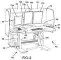
- FIG. 1is a photograph of the CT03 desk 10 .
- the CT03 desk 10includes first and second table sections 12 , 14 supported on a pair of telescoping legs 16 that are driven by a lift motor for changing the height of surfaces 12 a , 14 a of first and second tables above the floor.
- a first control switch 22allows a user to raise and lower the table surfaces 12 a , 14 a to a preferred seating height or higher, to a standing position.
- the table surfaces 12 a , 14 aextend laterally from the user's position.
- the first table surface 12 ais positioned in between the second table surface 14 a and the user's position.
- the display monitors(not shown) are mounted on display stands 24 attached to the second table surface 14 a , while the first table surface 12 a remains open for use as a work surface or as a platform for a keyboard.
- the first and second table sections 12 , 14are rigidly coupled together and motor driven for rotation relative to the legs 16 about a horizontal axis extending side-to-side, for thereby adjusting the tilt of the first and second table surfaces 12 a , 14 a in tandem.
- the table sections 12 , 14are driven for rotation in synchronization with an adjustment of the telescoping legs 16 so that the tilt of first table surface 12 a is adjusted without substantially changing the height position of a proximal edge 28 of the first table surface 12 a nearest the user. In this manner, the angle of the first table surface 12 a can be adjusted without requiring a user to change the height of his or her chair to accommodate the movement of the first table section 12 .
- each of the display stands 24includes a pole 30 fixedly attached to the second table surface 14 a and a pair of swing arms 32 mounted extending laterally from boom 30 .
- Each swing arm 32can each be articulated for adjusting a depth position of the display mounted thereon (not shown).
- the swing arms 32are also movable vertically along pole 30 to adjust the height of the display monitors. To prevent inadvertent movement of the display monitors when the second table surface 14 a is tilted, screws in shoulder and elbow joints 34 of the swing arms 32 are tightened once the displays are positioned where desired.
- US 2006/0075933 A1describes a supporting arrangement for a presentation device such as an image display monitor, wherein a supporting arrangement and a work surface are coupled for relative angular movement for adjusting both a tilt of the work surface and a viewing angle of the presentation device; and US 2006/0244717 A1 describes a system for automatically adjusting workplace illumination in response to changes in the intensity of images displayed on a computer display monitor.
- U.S. Patent No. 6,296,408 of Larkin et al.describes a workstation having a motorized support for a computer monitor that is automatically controlled by a computer controller programmed to continuously make imperceptible adjustments to a chair position, a footrest position, a keyboard position, and/or a monitor position to prevent worker fatigue and/or repetitive stress disorders.
- the Larkin et al. mechanism for moving a monitoris disclosed as a height adjuster secured to a non-rotatable work table with a vertically extending support coupled to the height adjuster.
- a monitor distance adjusteris secured to the support and horizontally moves a monitor support that extends through the monitor distance adjuster.
- the present inventorshave recognized a need for an improved desk and desktop display stand enabling ergonomic configuration.
- FIG. 1is an illustration of a desk and display stand in accordance with the prior art
- FIG. 2is a front pictorial view of a desk and display stand in accordance with an embodiment with a computer and display monitors installed;
- FIG. 2Ais a front elevation view of the desk and display stand of FIG. 2 in an alternate configuration with two computers and three display monitors installed;
- FIG. 3is a top view of the desk and display stand of FIG. 2 showing detail of first and second table sections and illustrating the locations of first and second control panels and task lights mounted on the first table section near a rear margin thereof;
- FIG. 4is a enlarged front view of the table surfaces and display stand of FIG. 2 with display monitors omitted to show detail of the display stand;
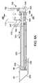
- FIG. 5is an enlarged front right view of the display stand of FIG. 2 ;
- FIG. 6is an enlarged pictorial view of the first control panel of FIG. 3 , showing detail of the desk height and tilt controls and the monitor height and depth controls;
- FIG. 7is an enlarged pictorial view of the second control panel of FIG. 3 , showing detail of lighting controls;
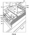
- FIG. 8is a top rear view of the display stand of FIGS. 2-5 with a collapsible accordion cover of the display stand retracted to reveal glides and a drive screw of a sled portion of the display stand in accordance with one embodiment;
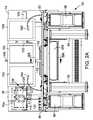
- FIG. 8Ais a sectional view taken along lines 8 A- 8 A of FIGS. 2A and 5 , showing sled drive details according to another embodiment
- FIG. 8Bis a sectional view taken along lines 8 B- 8 B of FIG. 8A , and showing further details of the display stand drive components;
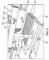
- FIG. 9is a rear view of the desk of FIGS. 2-5 with a privacy panel of the desk removed to show detail of the rear side of the display stand and cable management features of a rear frame portion of the desk;
- FIG. 10is a right side rear upper view of the display stand of FIGS. 2-5 showing detail of adjustable mounting features and cable management features of the display stand;
- FIG. 11is a front view of a boom extension arm of the display stand of FIG. 4 .
- a desk 50 in accordance with a first embodimentincludes a table unit 52 and display stand 56 supported on a base assembly 60 including first and second telescoping legs 62 , 64 .
- Legs 62 and 64include leg drive motors (not shown) for adjusting a height of table unit 52 and the display stand 56 mounted thereon.
- a CPU holder 66is suspended from table unit 52 to hold a computer 68 .
- Display monitors 70 a , 70 b , 70 c , and 70 d(hereinafter collectively “display monitors 70 ”) are shown in FIG. 2 mounted to display stand 56 .
- a privacy panel 74extends along the rear of table unit 52 behind display monitors 70 .
- a set of backlights 76are mounted adjacent a front surface of privacy panel 74 to provide backlighting illumination behind display monitors 70 for enhancing the visibility of images displayed on display monitors 70 .
- Table unit 52includes first, second, and third table sections 82 , 84 , and 86 .
- Second table section 84is located along a rear edge 88 of first table section 82 .
- Display stand 56is mounted on second table section 84 as further described below with reference to FIGS. 3-5 , and 8 .
- First and second table sections 82 and 84are preferably coupled together and rotatable in tandem to adjust a tilt thereof, in the manner of the prior art CT03 desk described above with reference to FIG. 1 .
- first and second table sections 82 and 84may be independently rotatable relative to legs 62 , 64 or coupled for rotation about spaced-apart first and second axes, respectively, in the manner described in publication No.
- Third table section 86remains level to provide a convenient non-tilting surface for items such as beverages and telephones, for example.
- First and second control panels 92 and 94are located in the respective rear right and rear left corners of first table section 82 or in any other convenient location. Control panels 92 and 94 are described below with reference to FIGS. 6 and 7 .
- display stand 56includes a sled assembly 100 having a sled 102 slidably mounted to second table section 84 for sliding movement along a first path extending in the direction of arrow 104 toward a user of desk 50 and at least partly under first table section 82 .
- sled assembly 100may be supported on another part of desk 50 different from second table section 84 , such as first table section 82 .
- first and second table sections 82 and 84may be combined as a single table having an opening for accommodating sled assembly 100 .
- part or all of table unit 52may provide a support platform for display stand 56 and, in some embodiments, may also provide a work surface or keyboard surface.
- Sled 102may preferably extend at least partly under the support platform or, in some embodiments, may extend within or into a cavity in the support platform and under a top surface of the support platform—which shall also be considered to be “under” the support platform for purposes of the present application. Sled 102 may also be movably mounted to a support platform other than slidably, for example, on a rack and pinion mechanism (not shown) or other suitable manner.
- Display stand 56further includes a mast 110 supported on the sled 102 and extending upwardly from sled assembly 100 through an elongate opening 202 ( FIG. 8 ) in table unit 52 .
- Mast 110includes a base member 112 attached to sled 102 and movable therewith along first path 104 within opening 202 .
- Mast 110further includes a moving member 116 operably engaged with base member 112 and movable upwardly relative to base member 112 along a second path 118 extending upwardly and generally perpendicular or transverse to first path 104 .
- Moving member 116supports thereon a display mount assembly 120 that is adapted for mounting one or more display monitors 70 thereon, for thereby suspending display monitors 70 above second table unit 52 .
- mast 110includes telescoping base and moving members 112 , 116 .
- mast 110may be configured differently for accomplishing a height adjustment.
- Sled assembly 100is driven for sliding movement of sled 102 toward and away from a front edge 121 of first table section 82 and a user of desk 50 by a sled drive 130 ( FIGS. 8 and 8A ).
- the sled drive 130may, thus, adjust a depth position of the display mounting assembly 120 supported on the sled, as further described below with reference to FIG. 8 .
- a mast drive including a mast drive motor 123( FIG. 8B ) is attached to the desk 50 , and preferably supported on the sled 102 and operably coupled to mast 110 for driving moving member 116 relative to base member 112 and sled 102 along a second path 118 , thereby adjusting a height of display mount assembly 120 relative to table assembly 52 .
- One suitable mast 110 with an integrated linear actuator mast driveis the Model DL1 DESKLIFTTM lifting column offered by Linak A/S of Guderup, Denmark.
- Display mount assembly 120includes a boom 122 and one or more boom extension arms 124 ( FIGS. 2A , 4 , and 11 ) extending laterally from mast 110 .
- Boom extension arms 124may be coupled to an end of boom 122 via shackles 125 extending from the mating ends of the boom 122 and boom extension arm 124 .
- the shackles 125are joined by a clevis pin forming part of an adjustable friction joint 126 for articulation of a distal end of boom extension arms 124 forward and aft relative to boom 122 about a pivot axis extending in a generally vertical direction through friction joint 126 .
- Friction joint 126includes a friction mechanism having a pair of knobs 128 that may be tightened and loosened to adjust the tension and holding power of the friction joint 126 to thereby maintain the position of a display monitor mounted to boom extension arm 124 during normal adjustment of table unit 52 and display stand 56 .
- Friction joint 126may also serve as a passive safety feature that allows boom extension arm 124 to rotate in the event that the boom extension arm 124 or a display monitor mounted thereto encounters an obstacle during adjustment of the depth of display stand 56 .
- boom 122could be divided into sections and a friction joint similar to friction joint 126 could be located at the place where the boom sections are coupled to mast 110 to provide a similar adjustability and passive safety feature for all of display monitors mounted to boom 122 , rather than just for the display monitor mounted to boom extension 124 .
- a controller of display stand 56( FIG. 3 ) includes a user interface 134 comprising a pair of rocker switches 136 , 138 located on first control panel 92 for actuating the respective mast drive motor 123 and sled drive 130 . Controller and user interface 134 thereby allow a user to adjust the height and depth positions of the display mounting assembly 120 to a desired position relative to table unit 52 .
- a second set of rocker switches 140 , 142are provided on first control panel 92 for controlling the respective height of table unit 52 and tilt of first table section 82 (which also concurrently adjusts the height of table unit 52 so as to maintain the height of front edge 121 of first table section 82 , as described above).
- a keypad 144is provided for interfacing with the controller and a memory thereof to store and recall up to 99 different user-defined table height and tilt settings for automatically returning the table unit 52 to a predefined position.
- keypad 144may also be utilized to store and recall multiple different user-defined display monitor height and depth settings for returning display stand 56 and display mounting assembly 120 to a predefined position.
- user-defined settings defining the positions of both the display stand 56 and table unit 52may be stored in memory and later recalled using keypad 144 for thereby simultaneously adjusting the position of display monitors 70 and table unit 52 to their predefined positions.
- User presetsmay facilitate convenient use of desk 50 by different users and for different purposes and user seating or standing positions.
- a fan switch 146 on first control panel 92switches a fan on and off. The fan includes a manually-adjustable louver assembly 148 for directing air blown by the fan as desired by a user.
- second control panel 94includes lighting controls 150 , including a backlight dimming dial 152 for manually adjusting the intensity setting of backlights 76 and an auto/manual toggle switch 154 for switching between a manual control mode and an automatic lighting control mode.
- the intensity of backlights 76is automatically adjusted in response to changes in the brightness of images displayed on display monitors 70 , as sensed by a photosensor 156 ( FIGS. 2 and 4 ) or by another means, such as monitoring of the display input signals.
- a task light dial 160is also located on second control panel 94 for adjusting the intensity of a pair of task lights 162 , 164 .
- a master lighting power switch 170is also provided for switching the task lights 162 , 164 and backlights 76 on and off. Finally a second fan is switched on and off by a second fan switch 174 on second control panel 94 , and a louver assembly 176 is manually adjustable to direct air blown by the fan.
- photosensor 156is mounted to the top of moving member 116 of mast 110 so that photosensor 156 moves in tandem with adjustments to the height and depth of display monitors 70 , thereby avoiding changes in the position of photosensor 156 relative to display monitors 70 .
- Photosensor 156may be supported on a flexible neck 158 that reaches from mast 110 to the front of display monitors 70 .
- Flexible neck 158may be manipulated to move photosensor 156 fore, aft, up, down, left, and right relative to display mount assembly 120 to thereby position photosensor 156 at a desired position during setup or later use of desk 50 , for example to accommodate different sizes and types of display monitors 70 . Maintaining the spacing and relative positioning of photosensor 156 relative to display monitors 70 during subsequent adjustment of the height and depth of the display stand 56 may provide improved consistency and convenience in automatic control of backlights 76 .
- sled assembly 100includes a sled tray 200 fixedly mounted within or adjacent an opening 202 in second table section 84 .
- Sled 102is slidably mounted to sled tray 200 via first and second sets of glides or forwardly-extending telescoping slides 208 a , 208 b , 212 a , 212 b , such as ball-bearing extension slides of the kind commonly used with desk drawers, for example.
- the first set of slides 208 a , 208 bis oriented vertically for supporting the weight of sled 102 , mast 110 and display monitors 70 .
- Sled drive 130is preferably mounted above sled tray 200 and includes a drive screw 220 extending in direction 104 ( FIG. 2 ) beneath sled 102 and rotatably supported on sled tray 200 via a shaft support bearing 246 .
- a spindle nut 245( FIG. 8A ) is rigidly coupled to sled 102 via mounting bracket 247 and threaded onto drive screw 220 for movement of sled 102 therealong in response to rotation of drive screw 220 by a sled drive motor 248 ( FIG. 8A ) of sled drive 130 .
- Sled tray 200 , sled 102 , and slides 208 , 212may be formed of steel or another strong, durable material capable of supporting the weight of display stand 56 and display monitors 70 .
- Sled drive motor 248may be electronically controlled by rocker switch 138 ( FIG. 6 ) of the controller independently of other motor-driven adjustments.
- sled drive motor 48may also be electronically controlled by keypad 144 , or may be controlled in concert with mast drive motor 123 and/or motor-driven adjustment features of table unit 52 .
- a pair of limit switches 224 , 226provide feedback to the sled drive motor controller for limiting the forward and rearward travel of sled 102 .
- One suitable sled driveis a Model DB5 linear actuator offered by Linak A/S of Guderup, Denmark.
- front and rear physical stops 250 , 254are employed to limit the range of movement of sled 102 .
- the sled motor controllermay “home” the sled 102 by moving the sled 102 to one or both of its forward and/or rearward physical limits of travel established by stops 250 , 254 , thereby causing a spike in the electrical current drawn by the sled drive motor 248 .
- the sled motor controlleridentifies a zero position for sled 102 , in other words a known position for sled 102 along drive screw 220 .
- the controllermay thereafter limit the forward and rearward travel of sled 102 relative to the zero position, for example, by counting the number of turns of sled motor 248 , controlling the amount of time the sled motor 248 is operated, or by any other suitable manner.
- the sled motor controllerstores the position of sled 102 in memory and uses the position of sled 102 to determine soft stops, that is, calculated or derived limits to the travel for sled 102 so sled 102 does not actually reach the physical limits of its travel after the initial homing operation.
- drive screw 220 of sled drive 130is located laterally off-center in the embodiment shown, to the right side of the mast 110 (as viewed from the user's seating position) to accommodate mast drive motor 123 .
- Mast drive motor 123is attached to an underside of sled 102 via a mast lift housing 257 suspended below and connected to sled 102 via a lift housing bracket 258 .
- the second set of slides 212 a , 212 bprovide torsional rigidity and counteract torque generated about a vertical axis by the moment arm between the coupling point of sled drive 130 to sled 102 and the center of mass of sled 102 and mast 110 .
- a collapsible accordion cover 240(shown retracted in FIG. 8 ; see also FIG. 5 ) extends between the rear margin of sled 102 and a back panel of sled tray 200 to cover sled drive 130 .
- Sled tray 200provides support for slides 208 a , 208 b , 212 a , 212 b and sled drive 130 .
- a sled guard 256extends below table unit 52 around and forward of the path 104 of movement of sled 102 to prevent sled 102 from hitting a user's knees when sled 102 is moved.
- a rubber wiper flap 259extends downwardly from rear margin 88 ( FIG. 3 ) of first table section 82 and against a top surface of sled 102 to prevent debris that may fall onto the top of sled 102 from inadvertently dropping under first table section 82 and into sled guard 256 .
- one or more cable management trays 260 or other cable management guides of different sizes and configurationsmay be mounted to boom 122 and boom extensions 124 to help organize, collect and guide cables extending between display monitors 70 and CPU 68 ( FIG. 2 ), power outlets 272 , and other locations.
- a flexible cable chain 264comprised of a series of hollow plastic links provide additional cable management for cables extending between display stand 56 and a rear frame 268 of desk 50 .
- Rear frame 268includes a cable raceway 270 around its perimeter between rear frame 268 and removable privacy panel 74 ( FIG.
- Rear frame 268includes a series of spaced-apart openings 282 formed therein and adjacent mounting holes 284 that facilitate connection of cable chain 264 to rear frame 268 at any of several locations and to allow more than one cable chain to be utilized with display stand 56 .
- there are six spaced-apart openings 282 and six corresponding sets of mounting holes 284 all spaced apart horizontally across rear frame 268but other embodiments could include more or fewer connection locations spaced apart and arranged in a different manner and more than one cable chain.
- boom 122 and boom extension 124include a multitude of threaded mounting holes 288 spaced apart along their length for selectively positioning cable management trays 260 , cable chain 264 , display mounting brackets 290 , an optional display power strip 294 , and other accessories at desired locations along the length of boom 122 and boom extension 124 .
- pivot joint 126provides a passive safety feature that allows boom extension arm 124 to pivot in the event that a display monitor mounted thereon encounters an obstacle while adjusting the depth position of display stand 56 .
- FIGS. 10 and 11a further passive safety feature is provided by display mounting brackets 290 .
- display mounting brackets 290include a mounting base 302 bolted to mounting holes 288 and a rotatable hangar bracket 304 pinned or bolted to mounting base 302 and supported thereon for free rotation upwardly about a generally horizontal axis in the event that an obstacle is encountered by a display monitor mounted thereon while adjustably lowering the display stand 56 .
- Video Electronics Standards Association (VESA) standard mounting brackets 310are preferably attached to display mounting brackets 290 via rotation joints 314 allowing three rotational degrees of freedom. Rotation joints 314 allow a user to adjust the tilt, pan, and yaw of the display monitor while providing enough frictional resistance to hold an attached display monitor in a desired position.
- VESAVideo Electronics Standards Association
- the term “desk”is intended to be broadly construed to include desks, tables, and other like devices including elevated work surfaces and a support base. Accordingly, references in the claims to “tables” and “table sections” should be construed to encompass work surfaces of tables and desks. It will be obvious to those having skill in the art that many changes may be made to the details of the above-described embodiments without departing from the underlying principles thereof. The scope of the present invention should, therefore, be determined only by the following claims.
Landscapes
- Devices For Indicating Variable Information By Combining Individual Elements (AREA)
Abstract
Description
Claims (20)
Priority Applications (1)
| Application Number | Priority Date | Filing Date | Title |
|---|---|---|---|
| US12/277,604US8051782B2 (en) | 2007-11-25 | 2008-11-25 | Desk and display stand with height and depth adjustment |
Applications Claiming Priority (2)
| Application Number | Priority Date | Filing Date | Title |
|---|---|---|---|
| US98997807P | 2007-11-25 | 2007-11-25 | |
| US12/277,604US8051782B2 (en) | 2007-11-25 | 2008-11-25 | Desk and display stand with height and depth adjustment |
Publications (2)
| Publication Number | Publication Date |
|---|---|
| US20090133609A1 US20090133609A1 (en) | 2009-05-28 |
| US8051782B2true US8051782B2 (en) | 2011-11-08 |
Family
ID=40668637
Family Applications (1)
| Application Number | Title | Priority Date | Filing Date |
|---|---|---|---|
| US12/277,604Active2030-01-23US8051782B2 (en) | 2007-11-25 | 2008-11-25 | Desk and display stand with height and depth adjustment |
Country Status (1)
| Country | Link |
|---|---|
| US (1) | US8051782B2 (en) |
Cited By (49)
| Publication number | Priority date | Publication date | Assignee | Title |
|---|---|---|---|---|
| US20100024691A1 (en)* | 2008-07-30 | 2010-02-04 | Weber Jeffrey A | Computer work station with moveable monitor support |
| US20130199420A1 (en)* | 2012-02-07 | 2013-08-08 | Kih-Utveckling Ab | Workplace with integrated interface for identification of a user |
| CN103371623A (en)* | 2012-04-20 | 2013-10-30 | 潘居然 | Multifunctional table |
| US8783193B2 (en)* | 2007-11-14 | 2014-07-22 | Abb Ab | Operator desk having synchronized displays |
| US20140208985A1 (en)* | 2013-01-25 | 2014-07-31 | Léon DesRoches | Workstation having automated and powered height, depth and rotational adjusters |
| US20140311050A1 (en)* | 2012-05-25 | 2014-10-23 | Brett Kincaid | Work and Videoconference Assembly |
| US8893628B2 (en) | 2013-03-04 | 2014-11-25 | Watson Furniture Group, Inc. | Dispatch desk with focal length adjustability |
| US20150138304A1 (en)* | 2012-05-14 | 2015-05-21 | Mcardell Roger Nicholas | Presentation and display equipment |
| US20150245707A1 (en)* | 2014-02-28 | 2015-09-03 | William SAAB | Desk assembly |
| US9167894B2 (en) | 2013-01-25 | 2015-10-27 | Sparx Smart Pods Inc. | Workstation having automated and powered height, depth and rotational adjusters |
| US20160270528A1 (en)* | 2012-11-13 | 2016-09-22 | Cgm Group Ab | Operator desk with adaptive armature |
| US9470357B2 (en)* | 2010-07-30 | 2016-10-18 | Ergotron, Inc. | Display positioning apparatus and method |
| US9554644B2 (en) | 2012-05-24 | 2017-01-31 | Varidesk, Llc | Adjustable desk platform |
| US9581285B2 (en) | 2010-07-30 | 2017-02-28 | Ergotron, Inc. | Cam balance mechanism systems and methods |
| US20170143117A1 (en)* | 2014-11-10 | 2017-05-25 | Eugenia Koulizakis | Portable Work Support And Keyboard/Mouse Tray and Work Station and Tethered Chair |
| US9720444B2 (en) | 2015-03-23 | 2017-08-01 | Ryan Nicholas HOLDEN | Furniture system for computer system having integral display |
| US9907396B1 (en) | 2012-10-10 | 2018-03-06 | Steelcase Inc. | Height adjustable support surface and system for encouraging human movement and promoting wellness |
| US9921726B1 (en) | 2016-06-03 | 2018-03-20 | Steelcase Inc. | Smart workstation method and system |
| US10038952B2 (en) | 2014-02-04 | 2018-07-31 | Steelcase Inc. | Sound management systems for improving workplace efficiency |
| US10085562B1 (en) | 2016-10-17 | 2018-10-02 | Steelcase Inc. | Ergonomic seating system, tilt-lock control and remote powering method and appartus |
| US10159336B2 (en) | 2016-09-23 | 2018-12-25 | Varidesk, Llc | Electrically-lifted computer desk and office desk thereof |
| US20190029414A1 (en)* | 2016-07-22 | 2019-01-31 | Eaton Intelligent Power Limited | Workstation with cable containment |
| US20190059574A1 (en)* | 2017-08-22 | 2019-02-28 | Anthony A. Paul | Method and apparatus for raising and lowering of desk within a work surface |
| US10285297B2 (en) | 2014-04-29 | 2019-05-07 | Bretford Manufacturing, Inc. | Recessed power system |
| US10376158B2 (en) | 2015-11-13 | 2019-08-13 | Sparx Smartpods Inc. | Systems and methods for controlling an interactive workstation based on biometric input |
| US20190343272A1 (en)* | 2018-05-14 | 2019-11-14 | Teknion Limited | Height-adjustable workstation and output-adjusting task light |
| US20190374025A1 (en)* | 2018-06-06 | 2019-12-12 | Innovative Office Products, Llc | Arm-based sit-stand workstation |
| US20200022492A1 (en)* | 2018-07-17 | 2020-01-23 | RedRick Technologies Inc. | Workstation with moveable table portion |
| USD879514S1 (en) | 2018-04-16 | 2020-03-31 | Playground Store Limited | Desk |
| EP3662786A1 (en)* | 2018-12-04 | 2020-06-10 | CKnapp Sales, Inc. | Synchronized monitor mount and desk height adjustment system |
| USD895325S1 (en) | 2018-04-16 | 2020-09-08 | Playground Store Limited | Desktop with stowed legs |
| US10768663B2 (en) | 2017-08-11 | 2020-09-08 | Xybix Systems, LLC | Apparatus for mounting a plurality of monitors having adjustable distance to a viewer |
| US10827829B1 (en) | 2012-10-10 | 2020-11-10 | Steelcase Inc. | Height adjustable support surface and system for encouraging human movement and promoting wellness |
| WO2021006987A1 (en)* | 2019-07-10 | 2021-01-14 | Ergotron, Inc. | Display mounting system and method |
| US10980339B2 (en)* | 2017-04-28 | 2021-04-20 | Evans Consoles Corporation | Equipment mounting apparatus for console |
| US11019920B2 (en) | 2016-09-23 | 2021-06-01 | Varidesk, Llc | Electrically-lifted computer desk and office desk thereof |
| US11051611B2 (en) | 2018-04-16 | 2021-07-06 | Playground Store Limited | Desk system |
| US11089865B2 (en) | 2018-12-04 | 2021-08-17 | CKnapp Sales, Inc. | Synchronized monitor mount and desk height adjustment system |
| US11266232B2 (en) | 2018-12-04 | 2022-03-08 | CKnapp Sales, Inc. | Automatic height adjustment system |
| US11284713B2 (en) | 2010-07-30 | 2022-03-29 | Ergotron, Inc. | Display positioning apparatus and method |
| US11297940B2 (en)* | 2016-10-18 | 2022-04-12 | Dataflex International B.V. | Office workplace system |
| US20220178493A1 (en)* | 2020-12-09 | 2022-06-09 | Lg Display Co., Ltd. | Display device and driving device for display device |
| US11357323B2 (en) | 2018-08-09 | 2022-06-14 | Eaton Intelligent Power Limited | Adjustable workstation with cable management |
| US11692666B2 (en) | 2020-12-29 | 2023-07-04 | Daniel Patrick Patell | Display stand that adjusts to the size of the item being displayed |
| US12022941B2 (en) | 2010-07-30 | 2024-07-02 | Ergotron, Inc. | Display positioning apparatus and method |
| US12228236B1 (en) | 2017-04-17 | 2025-02-18 | Manehu Product Alliance, Llc | Adjustable mounting systems for televisions |
| US12295493B2 (en) | 2020-02-08 | 2025-05-13 | Manehu Product Alliance, Llc | Display mounting system with adjustable weight counterbalance |
| US12316996B1 (en) | 2010-06-04 | 2025-05-27 | Manehu Product Alliance, Llc | Television mounting systems |
| US12376677B1 (en) | 2012-10-10 | 2025-08-05 | Steelcase Inc. | Ergonomic seating system, tilt-lock control and remote powering method and apparatus |
Families Citing this family (47)
| Publication number | Priority date | Publication date | Assignee | Title |
|---|---|---|---|---|
| US20080221930A1 (en) | 2007-03-09 | 2008-09-11 | Spacelabs Medical, Inc. | Health data collection tool |
| US20090273441A1 (en)* | 2008-05-05 | 2009-11-05 | International Business Machines Corporation | System and method for adjusting components within an office space |
| US9604020B2 (en) | 2009-10-16 | 2017-03-28 | Spacelabs Healthcare Llc | Integrated, extendable anesthesia system |
| US9022492B2 (en)* | 2010-12-17 | 2015-05-05 | Spacelabs Healthcare Llc | Sliding track and pivot mounting system for displays on anesthesia machines |
| CN102667423B (en) | 2009-10-16 | 2016-06-08 | 太空实验室健康护理有限公司 | light enhanced flow tube |
| BR112012011575A2 (en)* | 2009-10-16 | 2018-05-02 | Spacelabs Healthcare Llc | integrated and extensible anesthesia system |
| EP3503115A3 (en) | 2010-03-21 | 2019-10-23 | Spacelabs Healthcare LLC | Patient monitoring system |
| US8689705B2 (en) | 2010-06-02 | 2014-04-08 | Steelcase, Inc. | Reconfigurable table assemblies |
| US8667908B2 (en) | 2010-06-02 | 2014-03-11 | Steelcase Inc. | Frame type table assemblies |
| US9210999B2 (en) | 2010-06-02 | 2015-12-15 | Steelcase Inc. | Frame type table assemblies |
| US9185974B2 (en) | 2010-06-02 | 2015-11-17 | Steelcase Inc. | Frame type workstation configurations |
| WO2012068567A1 (en) | 2010-11-19 | 2012-05-24 | Spacelabs Healthcare, Llc | Dual serial bus interface |
| US9629566B2 (en) | 2011-03-11 | 2017-04-25 | Spacelabs Healthcare Llc | Methods and systems to determine multi-parameter managed alarm hierarchy during patient monitoring |
| DE102011007540A1 (en)* | 2011-04-15 | 2012-10-18 | Kesseböhmer Produktions GmbH & Co. KG | Calibratable telescope column, furniture with calibratable telescope column, and method for calibration of a telescope column |
| US8717506B2 (en)* | 2011-07-20 | 2014-05-06 | Hewlett-Packard Development Company, L.P. | Electronic video display mount |
| DE102012100847A1 (en)* | 2012-01-09 | 2013-07-11 | Josef Glöckl | Work table arrangement |
| US9089207B2 (en)* | 2012-09-05 | 2015-07-28 | Nucraft Furniture Company | Conference table with movable table top and ganging capability |
| US10987026B2 (en) | 2013-05-30 | 2021-04-27 | Spacelabs Healthcare Llc | Capnography module with automatic switching between mainstream and sidestream monitoring |
| US20140368476A1 (en)* | 2013-06-14 | 2014-12-18 | Hit Play Technologies Inc. | Furniture system with integrated display and low-voltage connectivity |
| US9702500B2 (en)* | 2014-02-10 | 2017-07-11 | Ami Entertainment Network, Llc | Jukebox mount with video displays |
| USD739771S1 (en)* | 2014-04-30 | 2015-09-29 | Thermo Electron Scientific Instruments Llc | Spectrometer |
| TWI539913B (en)* | 2014-08-29 | 2016-07-01 | 馗鼎奈米科技股份有限公司 | Intelligence computer table and chair system |
| US9998706B2 (en)* | 2014-11-13 | 2018-06-12 | Cisco Technology, Inc. | Video conference endpoint displays |
| US10139580B2 (en)* | 2014-11-24 | 2018-11-27 | Commscope Technologies Llc | Retractable datacommunications rack |
| US11191354B2 (en) | 2015-08-27 | 2021-12-07 | Xybix Systems, Inc. | Adjustable height desk with acoustical dome |
| US9949562B2 (en)* | 2015-08-27 | 2018-04-24 | Xybix Systems, Inc. | Adjustable height desk with acoustical dome |
| FI20155664A (en)* | 2015-09-16 | 2017-03-17 | Gistele Oy | Protective cover for connecting electrical and / or telecommunication cables to several objects |
| US10517392B2 (en) | 2016-05-13 | 2019-12-31 | Steelcase Inc. | Multi-tiered workstation assembly |
| US10039374B2 (en) | 2016-05-13 | 2018-08-07 | Steelcase Inc. | Multi-tiered workstation assembly |
| EP3565437B1 (en) | 2017-01-06 | 2023-03-15 | BAE Systems PLC | Workstation |
| GB2558575B (en)* | 2017-01-06 | 2022-05-11 | Bae Systems Plc | Workstation |
| EP3345503A1 (en)* | 2017-01-06 | 2018-07-11 | BAE SYSTEMS plc | Workstation |
| DE102017109188A1 (en)* | 2017-04-28 | 2018-10-31 | Knürr Technical Furniture GmbH | A workplace arrangement |
| US10779647B2 (en)* | 2017-06-21 | 2020-09-22 | New Deal Design, Llc | Office furniture system with integrated digital resources |
| DE102017116400A1 (en)* | 2017-07-20 | 2019-01-24 | Logicdata Electronic & Software Entwicklungs Gmbh | Electrically adjustable table system |
| AU2018236866A1 (en)* | 2017-10-02 | 2019-04-18 | SpaceCo Business Solutions, Inc. | System for reducing injury from pinch zones in adjustable height work surface assemblies |
| US12004487B2 (en)* | 2018-02-02 | 2024-06-11 | Gayle Peacock Gallagher | Animal safety constraint system |
| KR102072670B1 (en)* | 2018-03-21 | 2020-03-02 | (주)디인시스템 | Console desk |
| CN109827034B (en)* | 2018-09-30 | 2024-01-26 | 宜闻斯控制台(昆山)有限公司 | Console and console equipment installation device |
| CN118902469A (en) | 2019-06-26 | 2024-11-08 | 太空实验室健康护理有限公司 | Modifying monitored physiological data using data of body worn sensors |
| CN110301747B (en)* | 2019-08-05 | 2024-06-25 | 北京斯誉达电气设备有限公司 | Conference table with adjustable display screen position |
| US11607038B2 (en) | 2019-10-11 | 2023-03-21 | Ergotron, Inc. | Configuration techniques for an appliance with changeable components |
| US11419409B2 (en)* | 2019-12-12 | 2022-08-23 | David Raymond Koenig | Work station having a multi-purpose work surface |
| USD941612S1 (en) | 2020-06-11 | 2022-01-25 | Krueger International, Inc. | Privacy cove |
| US20220082201A1 (en)* | 2020-09-11 | 2022-03-17 | SWIFF TECHNOLOGY Co.,Ltd. | Computer bracket |
| CN113520042A (en)* | 2021-08-25 | 2021-10-22 | 河源职业技术学院 | Novel multimedia platform system |
| US12433399B2 (en)* | 2021-11-09 | 2025-10-07 | Google Llc | Desk with user selectable adjustments for hot desking |
Citations (16)
| Publication number | Priority date | Publication date | Assignee | Title |
|---|---|---|---|---|
| US4779922A (en) | 1986-11-25 | 1988-10-25 | Cooper Lloyd G B | Work station system |
| US4852500A (en)* | 1987-03-18 | 1989-08-01 | Herman Miller, Inc. | Integrated computer implement work area |
| US5101736A (en) | 1990-05-17 | 1992-04-07 | Bommarito Paul F | Adjustable surface desk for computers |
| US5437235A (en)* | 1993-06-10 | 1995-08-01 | Symbiote, Inc. | Computer work station |
| US5845587A (en)* | 1997-08-25 | 1998-12-08 | Signore, Incorporated | Two-part table top |
| US5909934A (en)* | 1998-07-24 | 1999-06-08 | Mcgraw; Jon | Computer desk |
| US5988076A (en)* | 1999-03-05 | 1999-11-23 | Nova-Link Limited | Combined cable manager and table connector |
| US6296408B1 (en) | 1993-08-05 | 2001-10-02 | Stephen F. Larkin | Programmed motion work station |
| US20020020329A1 (en)* | 2000-06-23 | 2002-02-21 | Kowalski Albert Shaw | Ergonomic visual display terminal and personal computer workstation apparatus |
| US6712008B1 (en)* | 2001-05-11 | 2004-03-30 | Bruce C. Habenicht | Portable computer work station assembly |
| US20050022699A1 (en)* | 2003-02-10 | 2005-02-03 | Roger Goza | Retractable multiposition furniture system |
| US20050217540A1 (en)* | 2004-03-31 | 2005-10-06 | Novak Daniel A | Emergency dispatch workstation |
| US20060065166A1 (en)* | 2004-09-30 | 2006-03-30 | Yueh Chi | Dual functional desk with tilt-adjustable tops |
| US7640866B1 (en)* | 2006-03-03 | 2010-01-05 | Widget Works, LLC | Mobile video panel display system |
| US7721658B2 (en)* | 2005-01-26 | 2010-05-25 | Herman Miller, Inc. | Computer workstation with movable monitor support |
| US7823973B2 (en)* | 2003-06-13 | 2010-11-02 | Vlad Dragusin | Integrated videogaming and computer workstation |
- 2008
- 2008-11-25USUS12/277,604patent/US8051782B2/enactiveActive
Patent Citations (16)
| Publication number | Priority date | Publication date | Assignee | Title |
|---|---|---|---|---|
| US4779922A (en) | 1986-11-25 | 1988-10-25 | Cooper Lloyd G B | Work station system |
| US4852500A (en)* | 1987-03-18 | 1989-08-01 | Herman Miller, Inc. | Integrated computer implement work area |
| US5101736A (en) | 1990-05-17 | 1992-04-07 | Bommarito Paul F | Adjustable surface desk for computers |
| US5437235A (en)* | 1993-06-10 | 1995-08-01 | Symbiote, Inc. | Computer work station |
| US6296408B1 (en) | 1993-08-05 | 2001-10-02 | Stephen F. Larkin | Programmed motion work station |
| US5845587A (en)* | 1997-08-25 | 1998-12-08 | Signore, Incorporated | Two-part table top |
| US5909934A (en)* | 1998-07-24 | 1999-06-08 | Mcgraw; Jon | Computer desk |
| US5988076A (en)* | 1999-03-05 | 1999-11-23 | Nova-Link Limited | Combined cable manager and table connector |
| US20020020329A1 (en)* | 2000-06-23 | 2002-02-21 | Kowalski Albert Shaw | Ergonomic visual display terminal and personal computer workstation apparatus |
| US6712008B1 (en)* | 2001-05-11 | 2004-03-30 | Bruce C. Habenicht | Portable computer work station assembly |
| US20050022699A1 (en)* | 2003-02-10 | 2005-02-03 | Roger Goza | Retractable multiposition furniture system |
| US7823973B2 (en)* | 2003-06-13 | 2010-11-02 | Vlad Dragusin | Integrated videogaming and computer workstation |
| US20050217540A1 (en)* | 2004-03-31 | 2005-10-06 | Novak Daniel A | Emergency dispatch workstation |
| US20060065166A1 (en)* | 2004-09-30 | 2006-03-30 | Yueh Chi | Dual functional desk with tilt-adjustable tops |
| US7721658B2 (en)* | 2005-01-26 | 2010-05-25 | Herman Miller, Inc. | Computer workstation with movable monitor support |
| US7640866B1 (en)* | 2006-03-03 | 2010-01-05 | Widget Works, LLC | Mobile video panel display system |
Non-Patent Citations (2)
| Title |
|---|
| AFC Industries, Inc., Engineering Drawing of DXET-6640-01, 1 page, archived at www.archive.org Dec. 24, 2005. |
| AFC Industries, Inc., Ergo Tier Deluxe, 1 page, http://www.afcindustries.com/ergo-delux-anim.htm, archived at www.archive.org Dec. 24, 2005. |
Cited By (100)
| Publication number | Priority date | Publication date | Assignee | Title |
|---|---|---|---|---|
| US8783193B2 (en)* | 2007-11-14 | 2014-07-22 | Abb Ab | Operator desk having synchronized displays |
| US20100024691A1 (en)* | 2008-07-30 | 2010-02-04 | Weber Jeffrey A | Computer work station with moveable monitor support |
| US8371237B2 (en)* | 2008-07-30 | 2013-02-12 | Herman Miller, Inc. | Computer work station with moveable monitor support |
| US12388949B1 (en) | 2010-06-04 | 2025-08-12 | Manehu Product Alliance, Llc | Television mounting systems |
| US12316996B1 (en) | 2010-06-04 | 2025-05-27 | Manehu Product Alliance, Llc | Television mounting systems |
| US9743757B2 (en) | 2010-07-30 | 2017-08-29 | Ergotron, Inc. | Edge mount positioning apparatus, system, and method |
| US9581285B2 (en) | 2010-07-30 | 2017-02-28 | Ergotron, Inc. | Cam balance mechanism systems and methods |
| US10939753B2 (en) | 2010-07-30 | 2021-03-09 | Ergotron, Inc. | Display positioning apparatus and method |
| US10172450B2 (en) | 2010-07-30 | 2019-01-08 | Ergotron, Inc. | Display positioning apparatus and method |
| US9820566B2 (en)* | 2010-07-30 | 2017-11-21 | Ergotron, Inc. | Display positioning apparatus and method |
| US9717329B2 (en) | 2010-07-30 | 2017-08-01 | Ergotron, Inc. | Display positioning apparatus and method |
| US11672334B2 (en) | 2010-07-30 | 2023-06-13 | Ergotron, Inc. | Display positioning apparatus and method |
| US11284713B2 (en) | 2010-07-30 | 2022-03-29 | Ergotron, Inc. | Display positioning apparatus and method |
| US9470357B2 (en)* | 2010-07-30 | 2016-10-18 | Ergotron, Inc. | Display positioning apparatus and method |
| US12022941B2 (en) | 2010-07-30 | 2024-07-02 | Ergotron, Inc. | Display positioning apparatus and method |
| US10667602B2 (en) | 2010-07-30 | 2020-06-02 | Ergotron, Inc. | Display positioning apparatus and method |
| US10104957B2 (en) | 2010-11-11 | 2018-10-23 | Ergotron, Inc. | Display and keyboard positioning apparatus, system, and method |
| US20130199420A1 (en)* | 2012-02-07 | 2013-08-08 | Kih-Utveckling Ab | Workplace with integrated interface for identification of a user |
| CN103371623A (en)* | 2012-04-20 | 2013-10-30 | 潘居然 | Multifunctional table |
| US9693015B2 (en)* | 2012-05-14 | 2017-06-27 | Roger Nicholas MCARDELL | Presentation and display equipment |
| US20150138304A1 (en)* | 2012-05-14 | 2015-05-21 | Mcardell Roger Nicholas | Presentation and display equipment |
| US9554644B2 (en) | 2012-05-24 | 2017-01-31 | Varidesk, Llc | Adjustable desk platform |
| US10413053B2 (en) | 2012-05-24 | 2019-09-17 | Varidesk, Llc | Adjustable desk platform |
| US9924793B2 (en) | 2012-05-24 | 2018-03-27 | Varidesk, Llc | Adjustable desk platform |
| US20140311050A1 (en)* | 2012-05-25 | 2014-10-23 | Brett Kincaid | Work and Videoconference Assembly |
| US11185158B1 (en) | 2012-05-25 | 2021-11-30 | Steelcase Inc. | Work and videoconference assembly |
| US11612240B1 (en) | 2012-05-25 | 2023-03-28 | Steelcase Inc. | Work and videoconference assembly |
| US10786074B2 (en) | 2012-05-25 | 2020-09-29 | Steelcase Inc. | Work and videoconference assembly |
| US11918116B1 (en) | 2012-10-10 | 2024-03-05 | Steelcase Inc. | Height adjustable support surface and system for encouraging human movement and promoting wellness |
| US10802473B2 (en) | 2012-10-10 | 2020-10-13 | Steelcase Inc. | Height adjustable support surface and system for encouraging human movement and promoting wellness |
| US10130169B1 (en) | 2012-10-10 | 2018-11-20 | Steelcase Inc. | Height adjustable support surface and system for encouraging human movement and promoting wellness |
| US10133261B2 (en) | 2012-10-10 | 2018-11-20 | Steelcase Inc. | Height-adjustable support surface and system for encouraging human movement and promoting wellness |
| US10130170B1 (en) | 2012-10-10 | 2018-11-20 | Steelcase Inc. | Height adjustable support surface and system for encouraging human movement and promoting wellness |
| US10866578B1 (en) | 2012-10-10 | 2020-12-15 | Steelcase Inc. | Height adjustable support surface and system for encouraging human movement and promoting wellness |
| US10827829B1 (en) | 2012-10-10 | 2020-11-10 | Steelcase Inc. | Height adjustable support surface and system for encouraging human movement and promoting wellness |
| US12376677B1 (en) | 2012-10-10 | 2025-08-05 | Steelcase Inc. | Ergonomic seating system, tilt-lock control and remote powering method and apparatus |
| US10209705B1 (en) | 2012-10-10 | 2019-02-19 | Steelcase Inc. | Height adjustable support surface and system for encouraging human movement and promoting wellness |
| US10206498B1 (en) | 2012-10-10 | 2019-02-19 | Steelcase Inc. | Height adjustable support surface and system for encouraging human movement and promoting wellness |
| US9971340B1 (en) | 2012-10-10 | 2018-05-15 | Steelcase Inc. | Height adjustable support surface and system for encouraging human movement and promoting wellness |
| US10719064B1 (en) | 2012-10-10 | 2020-07-21 | Steelcase Inc. | Height adjustable support surface and system for encouraging human movement and promoting wellness |
| US10691108B1 (en) | 2012-10-10 | 2020-06-23 | Steelcase Inc. | Height adjustable support surface and system for encouraging human movement and promoting wellness |
| US9907396B1 (en) | 2012-10-10 | 2018-03-06 | Steelcase Inc. | Height adjustable support surface and system for encouraging human movement and promoting wellness |
| US9560913B2 (en)* | 2012-11-13 | 2017-02-07 | Abb Ab | Operator desk with adaptive armature |
| US20160270528A1 (en)* | 2012-11-13 | 2016-09-22 | Cgm Group Ab | Operator desk with adaptive armature |
| US8991320B2 (en)* | 2013-01-25 | 2015-03-31 | Sparx Smart Pods Inc. | Workstation having automated and powered height, depth and rotational adjusters |
| US10314391B2 (en) | 2013-01-25 | 2019-06-11 | Sparx Smart Pods Inc. | Workstation having automated and powered height, depth and rotational adjusters |
| US20140208985A1 (en)* | 2013-01-25 | 2014-07-31 | Léon DesRoches | Workstation having automated and powered height, depth and rotational adjusters |
| US10548395B2 (en) | 2013-01-25 | 2020-02-04 | Sparx Smart Pods Inc. | Workstation having automated and powered height, depth and rotational adjusters |
| US9167894B2 (en) | 2013-01-25 | 2015-10-27 | Sparx Smart Pods Inc. | Workstation having automated and powered height, depth and rotational adjusters |
| US8893628B2 (en) | 2013-03-04 | 2014-11-25 | Watson Furniture Group, Inc. | Dispatch desk with focal length adjustability |
| US10419842B2 (en) | 2014-02-04 | 2019-09-17 | Steelcase Inc. | Sound management systems for improving workplace efficiency |
| US10869118B2 (en) | 2014-02-04 | 2020-12-15 | Steelcase Inc. | Sound management systems for improving workplace efficiency |
| US10038952B2 (en) | 2014-02-04 | 2018-07-31 | Steelcase Inc. | Sound management systems for improving workplace efficiency |
| US20150245707A1 (en)* | 2014-02-28 | 2015-09-03 | William SAAB | Desk assembly |
| US10285297B2 (en) | 2014-04-29 | 2019-05-07 | Bretford Manufacturing, Inc. | Recessed power system |
| US10736419B2 (en)* | 2014-11-10 | 2020-08-11 | Nikki Koulizakis | Portable work support and keyboard/mouse tray and work station and tethered chair |
| US20170143117A1 (en)* | 2014-11-10 | 2017-05-25 | Eugenia Koulizakis | Portable Work Support And Keyboard/Mouse Tray and Work Station and Tethered Chair |
| US9720444B2 (en) | 2015-03-23 | 2017-08-01 | Ryan Nicholas HOLDEN | Furniture system for computer system having integral display |
| US10376158B2 (en) | 2015-11-13 | 2019-08-13 | Sparx Smartpods Inc. | Systems and methods for controlling an interactive workstation based on biometric input |
| US11185238B2 (en) | 2015-11-13 | 2021-11-30 | Sparx Smartpods Inc. | Systems and methods for controlling an interactive workstation based on biometric input |
| US10459611B1 (en) | 2016-06-03 | 2019-10-29 | Steelcase Inc. | Smart workstation method and system |
| US9921726B1 (en) | 2016-06-03 | 2018-03-20 | Steelcase Inc. | Smart workstation method and system |
| US20190029414A1 (en)* | 2016-07-22 | 2019-01-31 | Eaton Intelligent Power Limited | Workstation with cable containment |
| US11019920B2 (en) | 2016-09-23 | 2021-06-01 | Varidesk, Llc | Electrically-lifted computer desk and office desk thereof |
| US10159336B2 (en) | 2016-09-23 | 2018-12-25 | Varidesk, Llc | Electrically-lifted computer desk and office desk thereof |
| US10631640B2 (en) | 2016-10-17 | 2020-04-28 | Steelcase Inc. | Ergonomic seating system, tilt-lock control and remote powering method and apparatus |
| US10863825B1 (en) | 2016-10-17 | 2020-12-15 | Steelcase Inc. | Ergonomic seating system, tilt-lock control and remote powering method and apparatus |
| US10085562B1 (en) | 2016-10-17 | 2018-10-02 | Steelcase Inc. | Ergonomic seating system, tilt-lock control and remote powering method and appartus |
| US10390620B2 (en) | 2016-10-17 | 2019-08-27 | Steelcase Inc. | Ergonomic seating system, tilt-lock control and remote powering method and apparatus |
| US11297940B2 (en)* | 2016-10-18 | 2022-04-12 | Dataflex International B.V. | Office workplace system |
| US12228236B1 (en) | 2017-04-17 | 2025-02-18 | Manehu Product Alliance, Llc | Adjustable mounting systems for televisions |
| US10980339B2 (en)* | 2017-04-28 | 2021-04-20 | Evans Consoles Corporation | Equipment mounting apparatus for console |
| US10768663B2 (en) | 2017-08-11 | 2020-09-08 | Xybix Systems, LLC | Apparatus for mounting a plurality of monitors having adjustable distance to a viewer |
| US11762420B2 (en) | 2017-08-11 | 2023-09-19 | Xybix Systems, Inc. | Apparatus for mounting a plurality of monitors having adjustable distance to a viewer |
| US10588403B2 (en)* | 2017-08-22 | 2020-03-17 | Anthony A. Paul | Method and apparatus for raising and lowering of desk within a work surface |
| US20190059574A1 (en)* | 2017-08-22 | 2019-02-28 | Anthony A. Paul | Method and apparatus for raising and lowering of desk within a work surface |
| USD895325S1 (en) | 2018-04-16 | 2020-09-08 | Playground Store Limited | Desktop with stowed legs |
| US11051611B2 (en) | 2018-04-16 | 2021-07-06 | Playground Store Limited | Desk system |
| USD879514S1 (en) | 2018-04-16 | 2020-03-31 | Playground Store Limited | Desk |
| US20190343272A1 (en)* | 2018-05-14 | 2019-11-14 | Teknion Limited | Height-adjustable workstation and output-adjusting task light |
| US11039684B2 (en)* | 2018-06-06 | 2021-06-22 | Innovative Office Products, Llc | Arm-based sit-stand workstation |
| US20190374025A1 (en)* | 2018-06-06 | 2019-12-12 | Innovative Office Products, Llc | Arm-based sit-stand workstation |
| US20200022492A1 (en)* | 2018-07-17 | 2020-01-23 | RedRick Technologies Inc. | Workstation with moveable table portion |
| US10709236B2 (en)* | 2018-07-17 | 2020-07-14 | RedRick Technologies Inc. | Workstation with moveable table portion |
| US11357323B2 (en) | 2018-08-09 | 2022-06-14 | Eaton Intelligent Power Limited | Adjustable workstation with cable management |
| CN111265003A (en)* | 2018-12-04 | 2020-06-12 | C纳普销售股份有限公司 | Synchronous adjusting system for height of monitor support and desk |
| US11553789B2 (en)* | 2018-12-04 | 2023-01-17 | CKnapp Sales, Inc. | Synchronized monitor mount and desk height adjustment system |
| US11412845B2 (en)* | 2018-12-04 | 2022-08-16 | CKnapp Sales, Inc. | Synchronized monitor mount and desk height adjustment system |
| US20220192364A1 (en)* | 2018-12-04 | 2022-06-23 | Cknapp Sales, Inc. D/B/A Vivo | Synchronized monitor mount and desk height adjustment system |
| EP3662786A1 (en)* | 2018-12-04 | 2020-06-10 | CKnapp Sales, Inc. | Synchronized monitor mount and desk height adjustment system |
| US11266232B2 (en) | 2018-12-04 | 2022-03-08 | CKnapp Sales, Inc. | Automatic height adjustment system |
| US11089865B2 (en) | 2018-12-04 | 2021-08-17 | CKnapp Sales, Inc. | Synchronized monitor mount and desk height adjustment system |
| US11725773B2 (en) | 2019-07-10 | 2023-08-15 | Ergotron, Inc. | Display mounting system and method |
| US11112057B2 (en) | 2019-07-10 | 2021-09-07 | Ergotron, Inc. | Display mounting system and method |
| WO2021006987A1 (en)* | 2019-07-10 | 2021-01-14 | Ergotron, Inc. | Display mounting system and method |
| US12209702B2 (en) | 2019-07-10 | 2025-01-28 | Ergotron, Inc. | Display mounting system and method |
| US12295493B2 (en) | 2020-02-08 | 2025-05-13 | Manehu Product Alliance, Llc | Display mounting system with adjustable weight counterbalance |
| US20220178493A1 (en)* | 2020-12-09 | 2022-06-09 | Lg Display Co., Ltd. | Display device and driving device for display device |
| US12031665B2 (en)* | 2020-12-09 | 2024-07-09 | Lg Display Co., Ltd. | Display device and driving device for display device |
| US11692666B2 (en) | 2020-12-29 | 2023-07-04 | Daniel Patrick Patell | Display stand that adjusts to the size of the item being displayed |
Also Published As
| Publication number | Publication date |
|---|---|
| US20090133609A1 (en) | 2009-05-28 |
Similar Documents
| Publication | Publication Date | Title |
|---|---|---|
| US8051782B2 (en) | Desk and display stand with height and depth adjustment | |
| US9655438B1 (en) | Ergonomic two-tier work station with height-adjustable work platforms | |
| EP1848916B1 (en) | Display device and stand therefor | |
| US8893628B2 (en) | Dispatch desk with focal length adjustability | |
| US6076785A (en) | Ergonomic sit/stand keyboard support mechanism | |
| US7690317B2 (en) | Computer workstation with moveable monitor support | |
| US4440096A (en) | Adjustable word processing table and the like | |
| EP3395201B1 (en) | Equipment mounting apparatus for a console | |
| US7721658B2 (en) | Computer workstation with movable monitor support | |
| US20080173774A1 (en) | Accessory Holder | |
| US6935250B1 (en) | Adjustable height table with multiple legs operable by a single crank | |
| US11000125B2 (en) | Configurable computer workstation | |
| US20090173847A1 (en) | Accessory Holder | |
| US20050217540A1 (en) | Emergency dispatch workstation | |
| US20100001563A1 (en) | Computer display viewing support | |
| US20190343272A1 (en) | Height-adjustable workstation and output-adjusting task light | |
| SE532789C2 (en) | Table with synchronized displays | |
| US11357679B2 (en) | Motorized mount for seating system | |
| EP3123899B1 (en) | Table with operating units adjustable in height | |
| CA3117691A1 (en) | Integrated patient support and equipment for medical procedures | |
| US4539913A (en) | Work table | |
| US10842693B2 (en) | Motorized mount for seating system | |
| CN200987480Y (en) | Adjustable notebook computer working table | |
| CN219049270U (en) | Massage bed equipment | |
| US20050150438A1 (en) | Motorized adjustable workstation |
Legal Events
| Date | Code | Title | Description |
|---|---|---|---|
| AS | Assignment | Owner name:ANTHRO CORPORATION, OREGON Free format text:ASSIGNMENT OF ASSIGNORS INTEREST;ASSIGNORS:NETHKEN, JERRY LEE;LINDER, STEVEN E.;GRIFFITH, GEORGE W.;AND OTHERS;REEL/FRAME:022041/0737 Effective date:20081211 | |
| STCF | Information on status: patent grant | Free format text:PATENTED CASE | |
| AS | Assignment | Owner name:BANK OF AMERICA, N.A., NEW YORK Free format text:INTELLECTUAL PROPERTY SECURITY AGREEMENT SUPPLEMENT;ASSIGNOR:ANTHRO CORPORATION;REEL/FRAME:035108/0586 Effective date:20150220 | |
| AS | Assignment | Owner name:WELLS FARGO BANK, NATIONAL ASSOCIATION, AS COLLATE Free format text:SECURITY INTEREST;ASSIGNOR:ANTHRO CORPORATION;REEL/FRAME:035070/0506 Effective date:20150220 | |
| FPAY | Fee payment | Year of fee payment:4 | |
| AS | Assignment | Owner name:ERGOTRON, INC., MINNESOTA Free format text:ASSIGNMENT OF ASSIGNORS INTEREST;ASSIGNOR:ANTHRO CORPORATION;REEL/FRAME:037331/0540 Effective date:20150824 | |
| AS | Assignment | Owner name:ERGOTRON, INC., MINNESOTA Free format text:MERGER;ASSIGNOR:ANTHRO CORPORATION;REEL/FRAME:037739/0062 Effective date:20160101 | |
| AS | Assignment | Owner name:ANTHRO CORPORATION, OREGON Free format text:NOTICE OF RELEASE OF SECURITY INTEREST IN PATENTS;ASSIGNOR:WELLS FARGO BANK, NATIONAL ASSOCIATION;REEL/FRAME:041346/0092 Effective date:20160831 | |
| MAFP | Maintenance fee payment | Free format text:PAYMENT OF MAINTENANCE FEE, 8TH YR, SMALL ENTITY (ORIGINAL EVENT CODE: M2552); ENTITY STATUS OF PATENT OWNER: SMALL ENTITY Year of fee payment:8 | |
| AS | Assignment | Owner name:ERGOTRON, INC. (AS SUCCESSOR BY MERGER TO ANTHRO CORPORATION), MINNESOTA Free format text:TERMINATION AND RELEASE OF INTELLECTUAL PROPERTY SECURITY AGREEMENT SUPPLEMENT;ASSIGNOR:BANK OF AMERICA, N.A.;REEL/FRAME:060560/0421 Effective date:20220615 | |
| AS | Assignment | Owner name:PNC BANK, NATIONAL ASSOCIATION, PENNSYLVANIA Free format text:GRANT OF PATENT SECURITY INTEREST;ASSIGNOR:ERGOTRON, INC.;REEL/FRAME:060613/0415 Effective date:20220706 | |
| MAFP | Maintenance fee payment | Free format text:PAYMENT OF MAINTENANCE FEE, 12TH YR, SMALL ENTITY (ORIGINAL EVENT CODE: M2553); ENTITY STATUS OF PATENT OWNER: SMALL ENTITY Year of fee payment:12 |