US8051707B2 - Sensor arrangement - Google Patents
Sensor arrangementDownload PDFInfo
- Publication number
- US8051707B2 US8051707B2US12/941,223US94122310AUS8051707B2US 8051707 B2US8051707 B2US 8051707B2US 94122310 AUS94122310 AUS 94122310AUS 8051707 B2US8051707 B2US 8051707B2
- Authority
- US
- United States
- Prior art keywords
- sensor
- sensor housing
- interconnect device
- arrangement
- bracket
- Prior art date
- Legal status (The legal status is an assumption and is not a legal conclusion. Google has not performed a legal analysis and makes no representation as to the accuracy of the status listed.)
- Expired - Fee Related
Links
- 230000003287optical effectEffects0.000claimsabstractdescription82
- 230000005494condensationEffects0.000claimsdescription9
- 238000009833condensationMethods0.000claimsdescription9
- 230000008878couplingEffects0.000claimsdescription8
- 238000010168coupling processMethods0.000claimsdescription8
- 238000005859coupling reactionMethods0.000claimsdescription8
- 239000004020conductorSubstances0.000claimsdescription5
- 239000011888foilSubstances0.000claimsdescription4
- 239000000758substrateSubstances0.000claimsdescription2
- 230000015572biosynthetic processEffects0.000claims2
- XOMKZKJEJBZBJJ-UHFFFAOYSA-N1,2-dichloro-3-phenylbenzeneChemical compoundClC1=CC=CC(C=2C=CC=CC=2)=C1ClXOMKZKJEJBZBJJ-UHFFFAOYSA-N0.000description8
- 230000006835compressionEffects0.000description5
- 238000007906compressionMethods0.000description5
- 230000008901benefitEffects0.000description3
- 238000007688edgingMethods0.000description3
- 238000011156evaluationMethods0.000description2
- 238000000034methodMethods0.000description2
- 230000008569processEffects0.000description2
- 230000009118appropriate responseEffects0.000description1
- 238000005452bendingMethods0.000description1
- 238000005352clarificationMethods0.000description1
- 238000010276constructionMethods0.000description1
- 230000007246mechanismEffects0.000description1
- 239000002184metalSubstances0.000description1
- 229910052710siliconInorganic materials0.000description1
- 239000010703siliconSubstances0.000description1
- 238000009423ventilationMethods0.000description1
Images


Classifications
- B—PERFORMING OPERATIONS; TRANSPORTING
- B60—VEHICLES IN GENERAL
- B60S—SERVICING, CLEANING, REPAIRING, SUPPORTING, LIFTING, OR MANOEUVRING OF VEHICLES, NOT OTHERWISE PROVIDED FOR
- B60S1/00—Cleaning of vehicles
- B60S1/02—Cleaning windscreens, windows or optical devices
- B60S1/04—Wipers or the like, e.g. scrapers
- B60S1/06—Wipers or the like, e.g. scrapers characterised by the drive
- B60S1/08—Wipers or the like, e.g. scrapers characterised by the drive electrically driven
- B60S1/0818—Wipers or the like, e.g. scrapers characterised by the drive electrically driven including control systems responsive to external conditions, e.g. by detection of moisture, dirt or the like
- B60S1/0822—Wipers or the like, e.g. scrapers characterised by the drive electrically driven including control systems responsive to external conditions, e.g. by detection of moisture, dirt or the like characterized by the arrangement or type of detection means
- B60S1/0862—Wipers or the like, e.g. scrapers characterised by the drive electrically driven including control systems responsive to external conditions, e.g. by detection of moisture, dirt or the like characterized by the arrangement or type of detection means including additional sensors
- B60S1/0866—Wipers or the like, e.g. scrapers characterised by the drive electrically driven including control systems responsive to external conditions, e.g. by detection of moisture, dirt or the like characterized by the arrangement or type of detection means including additional sensors including a temperature sensor
- B—PERFORMING OPERATIONS; TRANSPORTING
- B60—VEHICLES IN GENERAL
- B60S—SERVICING, CLEANING, REPAIRING, SUPPORTING, LIFTING, OR MANOEUVRING OF VEHICLES, NOT OTHERWISE PROVIDED FOR
- B60S1/00—Cleaning of vehicles
- B60S1/02—Cleaning windscreens, windows or optical devices
- B60S1/04—Wipers or the like, e.g. scrapers
- B60S1/06—Wipers or the like, e.g. scrapers characterised by the drive
- B60S1/08—Wipers or the like, e.g. scrapers characterised by the drive electrically driven
- B60S1/0818—Wipers or the like, e.g. scrapers characterised by the drive electrically driven including control systems responsive to external conditions, e.g. by detection of moisture, dirt or the like
- B60S1/0822—Wipers or the like, e.g. scrapers characterised by the drive electrically driven including control systems responsive to external conditions, e.g. by detection of moisture, dirt or the like characterized by the arrangement or type of detection means
- B60S1/0874—Wipers or the like, e.g. scrapers characterised by the drive electrically driven including control systems responsive to external conditions, e.g. by detection of moisture, dirt or the like characterized by the arrangement or type of detection means characterized by the position of the sensor on the windshield
- B60S1/0881—Wipers or the like, e.g. scrapers characterised by the drive electrically driven including control systems responsive to external conditions, e.g. by detection of moisture, dirt or the like characterized by the arrangement or type of detection means characterized by the position of the sensor on the windshield characterized by the attachment means on the windshield
- G—PHYSICS
- G01—MEASURING; TESTING
- G01D—MEASURING NOT SPECIALLY ADAPTED FOR A SPECIFIC VARIABLE; ARRANGEMENTS FOR MEASURING TWO OR MORE VARIABLES NOT COVERED IN A SINGLE OTHER SUBCLASS; TARIFF METERING APPARATUS; MEASURING OR TESTING NOT OTHERWISE PROVIDED FOR
- G01D11/00—Component parts of measuring arrangements not specially adapted for a specific variable
- G01D11/24—Housings ; Casings for instruments
- G01D11/245—Housings for sensors
- G—PHYSICS
- G01—MEASURING; TESTING
- G01D—MEASURING NOT SPECIALLY ADAPTED FOR A SPECIFIC VARIABLE; ARRANGEMENTS FOR MEASURING TWO OR MORE VARIABLES NOT COVERED IN A SINGLE OTHER SUBCLASS; TARIFF METERING APPARATUS; MEASURING OR TESTING NOT OTHERWISE PROVIDED FOR
- G01D11/00—Component parts of measuring arrangements not specially adapted for a specific variable
- G01D11/30—Supports specially adapted for an instrument; Supports specially adapted for a set of instruments
- H—ELECTRICITY
- H05—ELECTRIC TECHNIQUES NOT OTHERWISE PROVIDED FOR
- H05K—PRINTED CIRCUITS; CASINGS OR CONSTRUCTIONAL DETAILS OF ELECTRIC APPARATUS; MANUFACTURE OF ASSEMBLAGES OF ELECTRICAL COMPONENTS
- H05K1/00—Printed circuits
- H05K1/02—Details
- H05K1/14—Structural association of two or more printed circuits
- H05K1/147—Structural association of two or more printed circuits at least one of the printed circuits being bent or folded, e.g. by using a flexible printed circuit
- B—PERFORMING OPERATIONS; TRANSPORTING
- B60—VEHICLES IN GENERAL
- B60S—SERVICING, CLEANING, REPAIRING, SUPPORTING, LIFTING, OR MANOEUVRING OF VEHICLES, NOT OTHERWISE PROVIDED FOR
- B60S1/00—Cleaning of vehicles
- B60S1/02—Cleaning windscreens, windows or optical devices
- B60S1/04—Wipers or the like, e.g. scrapers
- B60S1/06—Wipers or the like, e.g. scrapers characterised by the drive
- B60S1/08—Wipers or the like, e.g. scrapers characterised by the drive electrically driven
- B60S1/0818—Wipers or the like, e.g. scrapers characterised by the drive electrically driven including control systems responsive to external conditions, e.g. by detection of moisture, dirt or the like
- B60S1/0822—Wipers or the like, e.g. scrapers characterised by the drive electrically driven including control systems responsive to external conditions, e.g. by detection of moisture, dirt or the like characterized by the arrangement or type of detection means
- B60S1/0874—Wipers or the like, e.g. scrapers characterised by the drive electrically driven including control systems responsive to external conditions, e.g. by detection of moisture, dirt or the like characterized by the arrangement or type of detection means characterized by the position of the sensor on the windshield
- B60S1/0888—Wipers or the like, e.g. scrapers characterised by the drive electrically driven including control systems responsive to external conditions, e.g. by detection of moisture, dirt or the like characterized by the arrangement or type of detection means characterized by the position of the sensor on the windshield characterized by the attachment of the elements in a unit
- H—ELECTRICITY
- H05—ELECTRIC TECHNIQUES NOT OTHERWISE PROVIDED FOR
- H05K—PRINTED CIRCUITS; CASINGS OR CONSTRUCTIONAL DETAILS OF ELECTRIC APPARATUS; MANUFACTURE OF ASSEMBLAGES OF ELECTRICAL COMPONENTS
- H05K1/00—Printed circuits
- H05K1/18—Printed circuits structurally associated with non-printed electric components
- H05K1/189—Printed circuits structurally associated with non-printed electric components characterised by the use of a flexible or folded printed circuit
- H—ELECTRICITY
- H05—ELECTRIC TECHNIQUES NOT OTHERWISE PROVIDED FOR
- H05K—PRINTED CIRCUITS; CASINGS OR CONSTRUCTIONAL DETAILS OF ELECTRIC APPARATUS; MANUFACTURE OF ASSEMBLAGES OF ELECTRICAL COMPONENTS
- H05K2201/00—Indexing scheme relating to printed circuits covered by H05K1/00
- H05K2201/10—Details of components or other objects attached to or integrated in a printed circuit board
- H05K2201/10007—Types of components
- H05K2201/10121—Optical component, e.g. opto-electronic component
- H—ELECTRICITY
- H05—ELECTRIC TECHNIQUES NOT OTHERWISE PROVIDED FOR
- H05K—PRINTED CIRCUITS; CASINGS OR CONSTRUCTIONAL DETAILS OF ELECTRIC APPARATUS; MANUFACTURE OF ASSEMBLAGES OF ELECTRICAL COMPONENTS
- H05K2201/00—Indexing scheme relating to printed circuits covered by H05K1/00
- H05K2201/10—Details of components or other objects attached to or integrated in a printed circuit board
- H05K2201/10007—Types of components
- H05K2201/10151—Sensor
Definitions
- the present inventionrelates to a sensor arrangement having an optical sensor, a non-optical sensor, and a sensor holder in which the non-optical sensor is held by a bracket that is connected to the sensor holder and in which the sensor arrangement can be mounted to a vehicle window by the sensor holder.
- DE 20 2006 010 426 U1describes a sensor holder which is fabricated as a press bent part.
- the sheet metal frame that forms the sensor holdercan be latched with a support piece connected to a vehicle window.
- the sensor holderattaches a rain sensor centrally.
- the sensor holderhas a molded elastic retaining tongue that projects to the side.
- the tongueholds a condensation sensor which is miniaturized in comparison with the rain sensor. It is not clear from DE '426 how a cover piece surrounding the sensor mechanism can be fabricated in an advantageous manner. Further, DE '426 lacks information regarding how the electrical connection of the condensation sensor could be achieved advantageously.
- An object of the present inventionis a sensor arrangement having an optical sensor and a non-optical sensor in which the sensor arrangement is characterized by a simple and cost-effective overall assembly process and by an advantageously designed electrical connection to the sensors.
- the present inventionprovides a sensor arrangement having an optical sensor and a non-optical sensor.
- the sensor arrangementfurther includes a sensor housing cover and a sensor housing body.
- the sensor housing cover and the sensor housing bodyare attached to one another to form a sensor housing attachable to a vehicle window.
- the sensor housing cover and the sensor housing bodyeach having corresponding bracket sections which form a bracket connected to the sensor housing.
- the sensor arrangementfurther includes a main interconnect device and a flexible interconnect device.
- the main interconnect deviceis positioned within the sensor housing.
- the optical sensoris connected to the main interconnect device.
- the flexible interconnect deviceis connected to the main interconnect device and extends from the main interconnect device to the bracket connected to the sensor housing.
- the non-optical sensoris connected to the flexible interconnect device within the bracket and is held by the bracket.
- Embodiments of the present inventionprovide a sensor arrangement having at least one optical sensor and at least one non-optical sensor which can be fixed to a vehicle window by a sensor holder.
- the non-optical sensoris held by a bracket connected to the sensor holder.
- the sensor holderis embodied as a sensor housing including a sensor housing body and a sensor housing cover.
- the sensor housingreceives a main circuit carrier to which parts of the optical sensor are connected.
- the non-optical sensoris connected to the main circuit carrier by a flexible circuit carrier.
- a sensor arrangement in accordance with embodiments of the present inventionincludes an optical sensor, a non-optical sensor, a sensor holder, a main interconnect device such as a printed circuit board (PCB), and a flexible interconnect device such as a foil conductor or a flexible printed circuit substrate.
- the sensor holderis embodied as a sensor housing having a sensor housing body and a sensor housing cover. The sensor housing accommodates the main interconnect device.
- the optical sensoris connected to the main interconnect device.
- the non-optical sensoris connected to the flexible interconnect device.
- the flexible interconnect deviceis connected to the main interconnect device such that the non-optical sensor is connected to the main interconnect device and such that the optical sensor and the non-optical sensor are connected to each other.
- the sensor arrangement in accordance with embodiments of the present inventionis characterized by the optical and non-optical sensors being mounted such that they are distributed among a plurality of interconnect devices (i.e., the main and flexible interconnect devices) with the non-optical sensor being arranged on the flexible interconnect device.
- the sensorsform an electrical unit through the connection of the flexible interconnect device to the main interconnect device.
- the main interconnect devicecan be contacted through a common electrical interface of the sensor arrangement.
- the main and flexible interconnect devicescan be connected to the sensor housing as a pre-mounted mechanical unit. No close tolerances with respect to the positioning of the sensors relative to one another may need to be maintained as the flexible connection between the sensors can compensate for any tolerances.
- the flexible interconnect devicemay enable an elastic mounting of the non-optical sensor on the bracket of the sensor housing in a simple manner.
- the bracket of the sensor housingis formed as a component of the sensor housing instead of being formed as a separate part to be attached.
- the bracket of the sensor housingis formed as an integral section of both of the sensor housing body and the sensor housing cover.
- An advantage of the sensor assembly in accordance with embodiments of the present inventionmay be that the entire sensor arrangement can be fabricated by joining only a relatively small number of individual components by modular assembly.
- Another advantage of the sensor assembly in accordance with embodiments of the present inventionmay be that the main and flexible interconnect devices can be pre-mounted with one another in the sensor housing before assembly.
- the two interconnect devicescan thus be connected to one another electrically and mechanically in a simple and cost-effective manner, such as with a soldered connection, and added as a component to the sensor housing in a simple manner.
- the electrical connection of the two interconnect devicescan be made with a plug-and-socket connector.
- the interconnect devicescan thus be connected to one another either before or after assembly on the sensor housing if necessary. This enables a subsequent exchange of one of the interconnect devices and the accompanying sensor to be carried out simply at any time.
- the non-optical sensormay be advantageously arranged by being held by bars molded into the bracket of the sensor housing and pressed against the vehicle window by a spring.
- the optical sensoris at least one of a rain sensor and a light sensor.
- the non-optical sensoris either a condensation sensor or a combination of a temperature sensor and a humidity sensor.
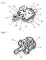
- FIG. 1illustrates a view of a sensor arrangement in accordance with an embodiment of the present invention with the sensor housing body of the sensor housing of the sensor arrangement being removed therefrom;
- FIG. 2illustrates a view of the sensor arrangement with the sensor housing cover of the sensor housing of the sensor arrangement being removed therefrom;
- FIG. 3illustrates a perspective view of the sensor arrangement looking up towards the sensor housing body
- FIG. 4illustrates a perspective view of the sensor arrangement looking down towards the sensor housing cover
- FIG. 5illustrates a view of the mounting of the non-optical sensor of the sensor arrangement on the bracket of the sensor housing with the sensor housing body being removed therefrom;
- FIG. 6illustrates a view according to FIG. 5 with the sensor housing cover and the sensor housing body attached to one another;
- FIG. 7illustrates a cross-sectional view of the view shown in FIG. 6 .
- the sensor arrangementincludes an optical sensor(s) 1 , a non-optical sensor(s) 2 , a sensor holder, a main interconnect device 5 , and a flexible interconnect device 6 .
- the sensor arrangementis fixable to a vehicle window or the like via the sensor holder.
- Optical sensor 1includes a plurality of electronic components such as a light transmitter 1 a and a plurality of light receivers 1 b , 1 c .
- Optical sensor 1is formed, for example, as a combined rain and light sensor.
- Non-optical sensor 2is formed, for example, as at least one of a condensation sensor, a temperature sensor, and a humidity sensor.
- the sensor holderis embodied as a sensor housing 13 (indicated in FIGS. 3 and 4 ) having a sensor housing cover 3 (shown in FIG. 1 ) and a sensor housing body 10 (shown in FIG. 2 ).
- Sensor housing cover 3attaches to sensor housing body 10 in order to form the assembled sensor housing 13 .
- FIGS. 1 and 2each illustrate views of the sensor arrangement with sensor housing 13 being disassembled. That is, FIGS. 1 and 2 each illustrate views of the sensor arrangement with sensor housing cover 3 being removed from sensor housing body 10 .
- FIG. 1illustrates an internal view of sensor housing cover 3 (i.e., FIG. 1 illustrates a view of the sensor arrangement with sensor housing body 10 being removed therefrom).
- FIG. 2illustrates an internal view of sensor housing body 10 (i.e., FIG. 2 illustrates a view of the sensor arrangement with sensor housing cover 3 being removed therefrom).
- Bracket sections 4 a , 4 bform a bracket 4 of sensor housing 13 when sensor housing 13 is assembled upon sensor housing cover 3 being attached to sensor housing body 10 (as shown in FIGS. 3 and 4 ).
- bracket section 4 b of sensor housing body 10surrounds bracket section 4 a of sensor housing cover 3 and bracket sections 4 a , 4 b together form bracket 4 of sensor housing 13 when sensor housing cover 3 is attached to sensor housing body 10 (this is particularly clearer in FIG. 6 ).
- Main interconnect device 5may be in the form of a printed circuit board (PCB).
- PCB 5is accommodated within sensor housing 13 .
- PCB 5is inserted into a frame shaped section of sensor housing cover 3 .
- PCB 5holds electronic components 1 a , 1 b , and 1 c of optical sensor 1 .
- PCB 5holds additional electronic components (not shown in detail) which form an evaluation circuit for sensor signals.
- PCB 5also forms a connection to an electrical interface 17 of the sensor arrangement. Electrical interface 17 is designed as a plug-and-socket connector on the outside of sensor housing cover 3 through which the output signals from the sensor arrangement can be accessed.
- Flexible interconnect device 6may be in the form of a foil conductor or a flexible circuit board. Flexible interconnect device 6 may be designed as a so-called Starflex conductor plate having rigid regions along with flexible sections.
- PCB 5accommodates a plug-and-socket connector 14 .
- PCB 5 and flexible interconnect device 6are electrically connected to one another via plug-and-socket connector 14 .
- PCB 5 and flexible interconnect device 6can be pre-assembled with one another and joined together at sensor housing cover 3 . This gives rise to a readily manageable component that can then be connected in a simple manner with sensor housing body 10 to form the sensor arrangement.
- Bracket section 4 aincludes a pair of bars 7 which stand upright perpendicular from bracket section 4 a towards bracket section 4 b of sensor housing body 10 . Bars 7 are parallel to one another. As described in greater detail below with respect to FIGS. 5 and 6 , the end of flexible interconnect device 6 routed to bracket section 4 a extends through bars 7 and bars 7 elastically hold non-optical sensor 2 .
- Non-optical sensor 2is connected to the end of flexible interconnect device 6 whereby non-optical sensor 2 is connected to main interconnect device 5 via flexible interconnect device 6 and plug-and-socket connector 14 . As indicated, optical sensor 1 is also connected to main interconnect device 5 .
- sensor housing body 10has a joined or molded light conducting arrangement 1 d .
- Light conducting arrangement 1 dtogether with electronic components 1 a , 1 b , and 1 c of optical sensor 1 in conjunction with a coupling surface 15 (shown in FIG. 3 ) of sensor housing body 10 form a plurality of optical sensors.
- Light conducting arrangement 1 dsets up light circuits between light transmitter(s) 1 a and light receiver(s) 1 b through which moistening of the vehicle window, of which the sensor arrangement is fixed to, can be optically detected.
- An additional light receiver 1 c of optical sensor 1receives light conducted from the vehicle surroundings through light conducting arrangement 1 d and thereby detects the brightness level outside the vehicle.
- sensor housing body 10includes a plurality of latching eyelets 16 .
- Latching eyelets 16are molded on corresponding edges of sensor housing body 10 .
- sensor housing cover 3includes a bracket 9 .
- Bracket 9includes a pair of first spring hooks 9 a and a plurality of second spring hooks 9 b .
- Second spring hooks 9 bpenetrate in a latching manner with corresponding ones of latching eyelets 16 of sensor housing body 10 when sensor housing cover 3 is attached to sensor housing body 10 to form the assembled sensor housing 13 .
- the sensor arrangementcan be attached to a support piece (not shown) that is connected to a vehicle window (not shown) in order to be fixed to the vehicle window.
- the sensor arrangementcan be glued to the vehicle window.
- FIG. 3illustrates a perspective view of the sensor arrangement looking up towards sensor housing body 10 .
- This side of sensor housing 13 which has sensor housing body 10faces the vehicle window when the sensor arrangement is fixed to the vehicle window.
- Sensor housing body 10includes coupling surface 15 on its outer side. Coupling surface 15 couples optical sensor 1 to the vehicle window. Coupling surface 15 is made, for example, of silicon.
- the end of flexible interconnect device 6 which is inside bracket 4 formed on sensor housing 13is pressed against the vehicle window by a compression spring 11 (shown in FIGS. 5 and 7 ) located inside bracket 4 . This end of flexible interconnect device 6 holds the side of non-optical sensor 2 facing the interior of sensor housing 13 .
- FIG. 4illustrates a perspective view of the sensor arrangement looking down towards sensor housing cover 3 .
- sensor housing cover 3includes bracket 9 which has the pair of first spring hooks 9 a and the plurality of second spring hooks 9 b .
- First spring hooks 9 aconnect sensor housing 13 with a support piece (not shown) attached to the vehicle window in order to fix the sensor arrangement to the vehicle window.
- second spring hooks 9 b of bracket 9project into latching eyelets 16 of sensor housing body 10 in order to connect sensor housing cover 3 and sensor housing body 10 together to form the assembled sensor housing 13 .
- second spring hooks 9 bproject into latching eyelets 16 in a latching manner thereby causing elastic bracket 9 to press sensor housing cover 3 against sensor housing body 10 .
- FIG. 5illustrates the area of the sensor arrangement associated with bracket section 4 a of sensor housing cover 3 with sensor housing body 10 being removed therefrom.
- FIG. 6illustrates a view according to FIG. 5 with sensor housing 10 assembled (i.e., with sensor housing cover 3 and sensor housing body 10 attached to one another).
- FIG. 7illustrates a cross-sectional view of the view shown in FIG. 6 .
- bars 7 on bracket section 4 a of sensor housing cover 3each have a recess 8 and non-optical sensor 2 has corresponding clip-type sections 18 .
- Clip-type sections 18 of non-optical sensor 2insert into recesses 8 of bars 7 .
- Clip-type sections 18can be displaced in the vertical direction along recesses 8 .
- Compression spring 11located between bars 7 , pushes non-optical sensor 2 away from the base surface of bracket section 4 a .
- non-optical sensor 2 and the end of flexible interconnect device 6 connected to the non-optical sensorprotrude a bit over the upper edge sections of bars 7 .
- bracket section 4 b of sensor housing body 10extends beyond bars 7 .
- Sensor housing body 10stabilizes bars 7 and helps prevent clip-type sections 18 of non-optical sensor 2 from slipping out of recesses 8 of bars 7 .
- Bars 7are surrounded by sensor housing body 10 for this reason.
- ribs (not shown) on sensor housing body 10join between bars 7 and hinder the inward bending of bars 7 to thereby hinder the clamping of non-optical sensor 2 located between bars 7 .
- Non-optical sensor 2 and flexible interconnect device 6extend beyond upper edging 19 of sensor housing body 10 .
- non-optical sensor 2 arranged on the back side of flexible interconnect device 6is thermally well coupled to the vehicle window. This is useful when non-optical sensor 2 includes a temperature sensor.
- non-optical sensor 2may include an air humidity sensor
- the side walls of sensor housing body 10include openings 12 around non-optical sensor 2 . Openings 12 assist in ventilating the humidity sensor.
- An evaluation circuitidentifies the instantaneous tendency toward condensation from the combined measured values of window temperature and air humidity such that even prior to the occurrence of condensation on the vehicle window an appropriate response can be initiated.
- FIG. 7illustrates a cross-sectional view through the assembly shown in FIG. 6 .
- Compression spring 11shown in greater detail in FIG. 7 , is mounted on a dome 20 molded on sensor housing cover 3 .
- the relatively narrow cross-section of flexible interconnect device 6enables non-optical sensor 2 to couple to the vehicle window through flexible interconnect device 6 .
- the flexible construction of flexible interconnect device 6also enables the use of the spring mounted assembly of non-optical sensor 2 .
Landscapes
- Engineering & Computer Science (AREA)
- Physics & Mathematics (AREA)
- General Physics & Mathematics (AREA)
- Automation & Control Theory (AREA)
- Mechanical Engineering (AREA)
- Microelectronics & Electronic Packaging (AREA)
- Investigating Or Analysing Materials By Optical Means (AREA)
- Photometry And Measurement Of Optical Pulse Characteristics (AREA)
Abstract
Description
- 1 optical sensor
- 1alight transmitter
- 1b,1clight receivers
- 1dlight conducting arrangement
- 2 non-optical sensor
- 3 sensor housing cover
- 4 bracket
- 4a,4bbracket sections
- 5 main interconnect device (e.g., printed circuit board)
- 6 flexible interconnect device (e.g., conductor foil)
- 7 bars
- 8 recesses of bars (for clipping in the non-optical sensor)
- 9 bracket
- 9afirst spring hooks
- 9bsecond spring hooks
- 10 sensor housing body
- 11 compression spring
- 12 ventilation openings
- 13 sensor housing
- 14 plug-and-socket connector
- 15 coupling surface
- 16 latching eyelets
- 17 electrical connection
- 18 clip-like sections of the non-optical sensor
- 19 edging
- 20 dome
Claims (20)
Applications Claiming Priority (4)
| Application Number | Priority Date | Filing Date | Title |
|---|---|---|---|
| DE102008028977.9 | 2008-06-18 | ||
| DE102008028977ADE102008028977A1 (en) | 2008-06-18 | 2008-06-18 | sensor arrangement |
| DE102008028977 | 2008-06-18 | ||
| PCT/EP2009/057459WO2009153256A1 (en) | 2008-06-18 | 2009-06-16 | Sensor arrangement |
Related Parent Applications (1)
| Application Number | Title | Priority Date | Filing Date |
|---|---|---|---|
| PCT/EP2009/057459ContinuationWO2009153256A1 (en) | 2008-06-18 | 2009-06-16 | Sensor arrangement |
Publications (2)
| Publication Number | Publication Date |
|---|---|
| US20110061445A1 US20110061445A1 (en) | 2011-03-17 |
| US8051707B2true US8051707B2 (en) | 2011-11-08 |
Family
ID=41010468
Family Applications (1)
| Application Number | Title | Priority Date | Filing Date |
|---|---|---|---|
| US12/941,223Expired - Fee RelatedUS8051707B2 (en) | 2008-06-18 | 2010-11-08 | Sensor arrangement |
Country Status (5)
| Country | Link |
|---|---|
| US (1) | US8051707B2 (en) |
| EP (1) | EP2296946B1 (en) |
| DE (1) | DE102008028977A1 (en) |
| ES (1) | ES2425955T3 (en) |
| WO (1) | WO2009153256A1 (en) |
Cited By (17)
| Publication number | Priority date | Publication date | Assignee | Title |
|---|---|---|---|---|
| US20110129209A1 (en)* | 2008-08-28 | 2011-06-02 | Leopold Kostal Gmbh & Co. Kg | Sensor assembly for a vehicle windshield |
| US20110155874A1 (en)* | 2008-08-28 | 2011-06-30 | Leopold Kostal Gmbh & Co. Kg | Sensor arrangement for a vehicle window |
| US8405726B2 (en) | 2002-01-31 | 2013-03-26 | Donnelly Corporation | Vehicle accessory system |
| US8481916B2 (en) | 1998-01-07 | 2013-07-09 | Magna Electronics Inc. | Accessory mounting system for a vehicle having a light absorbing layer with a light transmitting portion for viewing through from an accessory |
| US8513590B2 (en) | 1998-01-07 | 2013-08-20 | Magna Electronics Inc. | Vehicular accessory system with a cluster of sensors on or near an in-cabin surface of the vehicle windshield |
| US8531278B2 (en) | 2000-03-02 | 2013-09-10 | Magna Electronics Inc. | Accessory system for vehicle |
| US8531279B2 (en) | 1999-08-25 | 2013-09-10 | Magna Electronics Inc. | Accessory mounting system for a vehicle |
| US8534887B2 (en) | 1997-08-25 | 2013-09-17 | Magna Electronics Inc. | Interior rearview mirror assembly for a vehicle |
| US8570374B2 (en) | 2008-11-13 | 2013-10-29 | Magna Electronics Inc. | Camera for vehicle |
| US8686840B2 (en) | 2000-03-31 | 2014-04-01 | Magna Electronics Inc. | Accessory system for a vehicle |
| US8692659B2 (en) | 1998-01-07 | 2014-04-08 | Magna Electronics Inc. | Accessory mounting system for vehicle |
| US9090213B2 (en) | 2004-12-15 | 2015-07-28 | Magna Electronics Inc. | Accessory mounting system for a vehicle |
| US9233645B2 (en) | 1999-11-04 | 2016-01-12 | Magna Electronics Inc. | Accessory mounting system for a vehicle |
| US9434314B2 (en) | 1998-04-08 | 2016-09-06 | Donnelly Corporation | Electronic accessory system for a vehicle |
| CN111213297A (en)* | 2017-10-19 | 2020-05-29 | 维宁尔美国公司 | Ratchet fit cover for sensor housing |
| EP3789740A1 (en)* | 2019-09-06 | 2021-03-10 | MEAS France | Sensing device for a windshield |
| US20220194172A1 (en)* | 2019-04-11 | 2022-06-23 | Valeo Schalter Und Sensoren Gmbh | Sensor unit for vehicles |
Families Citing this family (16)
| Publication number | Priority date | Publication date | Assignee | Title |
|---|---|---|---|---|
| DE102010026563A1 (en)* | 2010-07-08 | 2012-01-12 | Hella Kgaa Hueck & Co. | Sensor arrangement for detecting state variables |
| KR101725550B1 (en)* | 2010-12-16 | 2017-04-10 | 삼성전자주식회사 | Portable terminal with optical touch pad and method for controlling data in the portable terminal |
| DE102011105167A1 (en)* | 2011-06-21 | 2012-12-27 | Valeo Schalter Und Sensoren Gmbh | Sensor device for use in arrangement of vehicle for ambient light measurement of vehicle or tunnel detection, comprises housing, in which rain sensor is arranged, and gas sensor, which is arranged in housing |
| DE102011121003A1 (en) | 2011-12-13 | 2013-06-13 | Daimler Ag | Carrier device for attachment to a disc and mounting arrangement of a camera or the like on such a support device |
| DE102011122456A1 (en)* | 2011-12-24 | 2013-06-27 | Valeo Schalter Und Sensoren Gmbh | Optical sensor with an integrated humidity sensor |
| US9709461B2 (en)* | 2012-11-30 | 2017-07-18 | Sensata Technologies, Inc. | Method of integrating a temperature sensing element |
| DE102013022060A1 (en)* | 2013-12-23 | 2015-06-25 | Valeo Schalter Und Sensoren Gmbh | Rain sensor unit |
| DE102015212988A1 (en)* | 2015-07-10 | 2017-01-12 | Robert Bosch Gmbh | A vehicle comprising an internal combustion engine driven by a gas |
| US10527523B2 (en)* | 2015-12-18 | 2020-01-07 | Ge Global Sourcing Llc | Vehicle sensor assembly having an RF sensor disposed in the sensor assembly to wirelessly communicate data to outside the sensor assembly |
| US10212776B2 (en)* | 2016-12-28 | 2019-02-19 | Asahi Kasei Microdevices Corporation | Light receiving device and light emitting and receiving device |
| DE102017204338A1 (en) | 2017-03-15 | 2018-09-20 | Robert Bosch Gmbh | Electronic control module and method of manufacturing an electronic control module |
| CN108802709B (en)* | 2017-05-04 | 2022-08-19 | 法拉第未来公司 | Improved laser radar shell |
| JP6659743B2 (en)* | 2018-01-18 | 2020-03-04 | 本田技研工業株式会社 | External sensor unit of vehicle |
| EP3628540B1 (en)* | 2018-09-25 | 2022-03-16 | MEAS France | Windshield sensing device |
| US11366019B2 (en)* | 2019-06-28 | 2022-06-21 | X Development Llc | Enhanced ambient temperature detection |
| US12429866B2 (en)* | 2019-10-11 | 2025-09-30 | Steering Solutions Ip Holding Corporation | Remote sensor system |
Citations (12)
| Publication number | Priority date | Publication date | Assignee | Title |
|---|---|---|---|---|
| DE3827937A1 (en) | 1988-08-12 | 1990-02-15 | Siemens Ag | Electrical measured value pick-up |
| US20030074962A1 (en)* | 2000-12-06 | 2003-04-24 | Helmut Sautter | Rain sensor, in particular for a motor vehicle |
| DE202006010426U1 (en) | 2006-07-06 | 2006-08-31 | A. Raymond Et Cie | Fixture for attaching sensor to carrier part, e.g. for rain or precipitation sensor, for motor vehicle, has bracket with baseplate whose area is larger than that of opposing plate provided with indexing device |
| DE102006032372A1 (en) | 2005-07-19 | 2007-02-15 | Preh Gmbh | Capacitive rain sensor |
| US20070044542A1 (en)* | 2002-12-03 | 2007-03-01 | Pascal Barguirdjian | Temperature compensated windshield moisture detector |
| DE102006022404A1 (en) | 2006-05-13 | 2007-11-15 | Hella Kgaa Hueck & Co. | Camera arrangement for use in inner side of windscreen of motor vehicle, has humidity sensor device for detecting humidification of windscreen of motor vehicle, where humidity sensor device is non-optical humidity sensor device |
| WO2008014911A1 (en) | 2006-07-29 | 2008-02-07 | Preh Gmbh | Modular sensor unit for a motor vehicle |
| DE102006060547A1 (en) | 2006-12-21 | 2008-06-26 | Hella Kgaa Hueck & Co. | Opto-electronic rain sensor, for a motor vehicle windscreen, has a radial arm at the housing for a temperature sensor using the rain sensor power supply to measure the windscreen inner surface temperature |
| DE102006060546A1 (en) | 2006-12-21 | 2008-06-26 | Hella Kgaa Hueck & Co. | Opto-electronic rain sensor, for a motor vehicle windscreen, has a U-shaped temperature sensor arm bonded to the sensor housing using the sensor power supply |
| DE102006060548A1 (en) | 2006-12-21 | 2008-06-26 | Hella Kgaa Hueck & Co. | Opto-electronic rain sensor, for a motor vehicle windscreen, has an additional temperature/air humidity sensor bonded to the housing using the rain sensor power supply |
| US7446427B2 (en)* | 2003-05-20 | 2008-11-04 | Gentex Corporation | Rearview mirror system for accommodating a rain sensor |
| US20090161109A1 (en)* | 2004-10-16 | 2009-06-25 | Frank Wolf | Optical sensor for detecting moisture on a window of a motor vehicle |
- 2008
- 2008-06-18DEDE102008028977Apatent/DE102008028977A1/ennot_activeWithdrawn
- 2009
- 2009-06-16ESES09765836Tpatent/ES2425955T3/enactiveActive
- 2009-06-16WOPCT/EP2009/057459patent/WO2009153256A1/enactiveApplication Filing
- 2009-06-16EPEP09765836.3Apatent/EP2296946B1/ennot_activeNot-in-force
- 2010
- 2010-11-08USUS12/941,223patent/US8051707B2/ennot_activeExpired - Fee Related
Patent Citations (17)
| Publication number | Priority date | Publication date | Assignee | Title |
|---|---|---|---|---|
| DE3827937A1 (en) | 1988-08-12 | 1990-02-15 | Siemens Ag | Electrical measured value pick-up |
| US20030074962A1 (en)* | 2000-12-06 | 2003-04-24 | Helmut Sautter | Rain sensor, in particular for a motor vehicle |
| US6810729B2 (en)* | 2000-12-06 | 2004-11-02 | Robert Bosch Gmbh | Rain sensor with a light-conducting body for a motor vehicle |
| US7296461B2 (en)* | 2002-12-03 | 2007-11-20 | Ppg Industries Ohio, Inc. | Temperature compensated windshield moisture detector |
| US20070044542A1 (en)* | 2002-12-03 | 2007-03-01 | Pascal Barguirdjian | Temperature compensated windshield moisture detector |
| US7446427B2 (en)* | 2003-05-20 | 2008-11-04 | Gentex Corporation | Rearview mirror system for accommodating a rain sensor |
| US20090161109A1 (en)* | 2004-10-16 | 2009-06-25 | Frank Wolf | Optical sensor for detecting moisture on a window of a motor vehicle |
| US20080223127A1 (en) | 2005-07-19 | 2008-09-18 | Hans-Michael Schmitt | Capacitive rain sensor |
| DE102006032372A1 (en) | 2005-07-19 | 2007-02-15 | Preh Gmbh | Capacitive rain sensor |
| US7716981B2 (en) | 2005-07-19 | 2010-05-18 | PRKH GmbH | Capacitive rain sensor |
| DE102006022404A1 (en) | 2006-05-13 | 2007-11-15 | Hella Kgaa Hueck & Co. | Camera arrangement for use in inner side of windscreen of motor vehicle, has humidity sensor device for detecting humidification of windscreen of motor vehicle, where humidity sensor device is non-optical humidity sensor device |
| DE202006010426U1 (en) | 2006-07-06 | 2006-08-31 | A. Raymond Et Cie | Fixture for attaching sensor to carrier part, e.g. for rain or precipitation sensor, for motor vehicle, has bracket with baseplate whose area is larger than that of opposing plate provided with indexing device |
| WO2008014911A1 (en) | 2006-07-29 | 2008-02-07 | Preh Gmbh | Modular sensor unit for a motor vehicle |
| US20090134985A1 (en) | 2006-07-29 | 2009-05-28 | Preh Gmbh | Modular sensor unit for a motor vehicle |
| DE102006060547A1 (en) | 2006-12-21 | 2008-06-26 | Hella Kgaa Hueck & Co. | Opto-electronic rain sensor, for a motor vehicle windscreen, has a radial arm at the housing for a temperature sensor using the rain sensor power supply to measure the windscreen inner surface temperature |
| DE102006060546A1 (en) | 2006-12-21 | 2008-06-26 | Hella Kgaa Hueck & Co. | Opto-electronic rain sensor, for a motor vehicle windscreen, has a U-shaped temperature sensor arm bonded to the sensor housing using the sensor power supply |
| DE102006060548A1 (en) | 2006-12-21 | 2008-06-26 | Hella Kgaa Hueck & Co. | Opto-electronic rain sensor, for a motor vehicle windscreen, has an additional temperature/air humidity sensor bonded to the housing using the rain sensor power supply |
Cited By (44)
| Publication number | Priority date | Publication date | Assignee | Title |
|---|---|---|---|---|
| US8534887B2 (en) | 1997-08-25 | 2013-09-17 | Magna Electronics Inc. | Interior rearview mirror assembly for a vehicle |
| US9718357B2 (en) | 1997-08-25 | 2017-08-01 | Magna Electronics Inc. | Vehicular accessory system |
| US8926151B2 (en) | 1997-08-25 | 2015-01-06 | Magna Electronics Inc. | Vehicular accessory system |
| US9035233B2 (en) | 1997-08-25 | 2015-05-19 | Magna Electronics Inc. | Accessory mounting system for mounting an electronic device at a windshield of a vehicle |
| US9527445B2 (en) | 1998-01-07 | 2016-12-27 | Magna Electronics Inc. | Accessory mounting system for mounting an accessory at a vehicle such that a camera views through the vehicle windshield |
| US8481916B2 (en) | 1998-01-07 | 2013-07-09 | Magna Electronics Inc. | Accessory mounting system for a vehicle having a light absorbing layer with a light transmitting portion for viewing through from an accessory |
| US8692659B2 (en) | 1998-01-07 | 2014-04-08 | Magna Electronics Inc. | Accessory mounting system for vehicle |
| US8513590B2 (en) | 1998-01-07 | 2013-08-20 | Magna Electronics Inc. | Vehicular accessory system with a cluster of sensors on or near an in-cabin surface of the vehicle windshield |
| US9434314B2 (en) | 1998-04-08 | 2016-09-06 | Donnelly Corporation | Electronic accessory system for a vehicle |
| US8531279B2 (en) | 1999-08-25 | 2013-09-10 | Magna Electronics Inc. | Accessory mounting system for a vehicle |
| US9283900B2 (en) | 1999-08-25 | 2016-03-15 | Magna Electronics Inc. | Accessory mounting system for a vehicle |
| US9446715B2 (en) | 1999-08-25 | 2016-09-20 | Magna Electronics Inc. | Vision system for a vehicle |
| US9539956B2 (en) | 1999-08-25 | 2017-01-10 | Magna Electronics Inc. | Accessory system for a vehicle |
| US9233645B2 (en) | 1999-11-04 | 2016-01-12 | Magna Electronics Inc. | Accessory mounting system for a vehicle |
| US8749367B2 (en) | 1999-11-04 | 2014-06-10 | Magna Electronics Inc. | Driver assistance system for a vehicle |
| US9637053B2 (en) | 1999-11-04 | 2017-05-02 | Magna Electronics Inc. | Accessory mounting system for a vehicle |
| US9193302B2 (en) | 1999-11-04 | 2015-11-24 | Magna Electronics Inc. | Vision system for a vehicle |
| US8531278B2 (en) | 2000-03-02 | 2013-09-10 | Magna Electronics Inc. | Accessory system for vehicle |
| US10059265B2 (en) | 2000-03-02 | 2018-08-28 | Magna Electronics Inc. | Vision system for a vehicle |
| US9843777B2 (en) | 2000-03-02 | 2017-12-12 | Magna Electronics Inc. | Cabin monitoring system for a vehicle |
| US10427604B2 (en) | 2000-03-02 | 2019-10-01 | Magna Electronics Inc. | Vision system for a vehicle |
| US9783125B2 (en) | 2000-03-31 | 2017-10-10 | Magna Electronics Inc. | Accessory system for a vehicle |
| US8686840B2 (en) | 2000-03-31 | 2014-04-01 | Magna Electronics Inc. | Accessory system for a vehicle |
| US8405726B2 (en) | 2002-01-31 | 2013-03-26 | Donnelly Corporation | Vehicle accessory system |
| US8508593B1 (en) | 2002-01-31 | 2013-08-13 | Magna Electronics | Vehicle accessory system |
| US10543786B2 (en) | 2002-01-31 | 2020-01-28 | Magna Electronics Inc. | Vehicle camera system |
| US9862323B2 (en) | 2002-01-31 | 2018-01-09 | Magna Electronics Inc. | Vehicle accessory system |
| US8749633B2 (en) | 2002-01-31 | 2014-06-10 | Magna Electronics Inc. | Vehicle accessory system |
| US9266474B2 (en) | 2004-08-18 | 2016-02-23 | Magna Electronics Inc. | Accessory system for vehicle |
| US8710969B2 (en) | 2004-08-18 | 2014-04-29 | Magna Electronics Inc. | Accessory system for vehicle |
| US10773724B2 (en) | 2004-08-18 | 2020-09-15 | Magna Electronics Inc. | Accessory system for vehicle |
| US10046714B2 (en) | 2004-12-15 | 2018-08-14 | Magna Electronics Inc. | Accessory mounting system for a vehicle |
| US9090213B2 (en) | 2004-12-15 | 2015-07-28 | Magna Electronics Inc. | Accessory mounting system for a vehicle |
| US10710514B2 (en) | 2004-12-15 | 2020-07-14 | Magna Electronics Inc. | Accessory mounting system for a vehicle |
| US20110129209A1 (en)* | 2008-08-28 | 2011-06-02 | Leopold Kostal Gmbh & Co. Kg | Sensor assembly for a vehicle windshield |
| US8448914B2 (en)* | 2008-08-28 | 2013-05-28 | Leopold Kostal Gmbh & Co. Kg | Sensor arrangement for a vehicle window |
| US8192095B2 (en)* | 2008-08-28 | 2012-06-05 | Leopold Kostal Gmbh & Co. Kg | Sensor assembly for a vehicle windshield |
| US20110155874A1 (en)* | 2008-08-28 | 2011-06-30 | Leopold Kostal Gmbh & Co. Kg | Sensor arrangement for a vehicle window |
| US8570374B2 (en) | 2008-11-13 | 2013-10-29 | Magna Electronics Inc. | Camera for vehicle |
| CN111213297A (en)* | 2017-10-19 | 2020-05-29 | 维宁尔美国公司 | Ratchet fit cover for sensor housing |
| EP3698443A4 (en)* | 2017-10-19 | 2021-10-27 | Veoneer US, Inc. | RATCHET COVER FOR SENSOR HOUSING |
| US20220194172A1 (en)* | 2019-04-11 | 2022-06-23 | Valeo Schalter Und Sensoren Gmbh | Sensor unit for vehicles |
| US12070988B2 (en)* | 2019-04-11 | 2024-08-27 | Valeo Schalter Und Sensoren Gmbh | Sensor unit for vehicles |
| EP3789740A1 (en)* | 2019-09-06 | 2021-03-10 | MEAS France | Sensing device for a windshield |
Also Published As
| Publication number | Publication date |
|---|---|
| WO2009153256A1 (en) | 2009-12-23 |
| DE102008028977A1 (en) | 2009-12-24 |
| ES2425955T3 (en) | 2013-10-18 |
| US20110061445A1 (en) | 2011-03-17 |
| EP2296946B1 (en) | 2013-05-29 |
| EP2296946A1 (en) | 2011-03-23 |
Similar Documents
| Publication | Publication Date | Title |
|---|---|---|
| US8051707B2 (en) | Sensor arrangement | |
| US8179438B2 (en) | Vehicle camera system | |
| US20130335276A1 (en) | Electronic communication device with antenna structure | |
| JPWO2017138152A1 (en) | Optical transceiver heat dissipation device and optical communication device | |
| US11927325B1 (en) | Linear lamp having splicing member | |
| US9518849B2 (en) | Acoustic sensor apparatus | |
| KR20170002995A (en) | Apparatus for Detecting Temperature and Humidity for Vehicle | |
| US7308206B2 (en) | Heatsinking of optical subassembly and method of assembling | |
| CN113811458B (en) | Vehicle sensor unit | |
| US20080258743A1 (en) | Condensation sensor | |
| KR101693024B1 (en) | A signal transfer assembly for sensor | |
| JPWO2010073397A1 (en) | Input/Output Unit | |
| CN210801081U (en) | Slender microwave inductor | |
| US7367718B2 (en) | Optical module | |
| US6396698B1 (en) | Retention module adapter | |
| US20030076565A1 (en) | Optical communication module | |
| US20040233319A1 (en) | Image sensing module | |
| JP2003112506A (en) | Transmitter for tire air pressure warning device | |
| JP4557392B2 (en) | Receiver module | |
| CN111178108B (en) | Scanning module and data collection terminal | |
| KR100710868B1 (en) | Vehicle window fogging detection device | |
| JP3098997U (en) | Amplifier for antenna | |
| KR20220052159A (en) | Auto defog sensor unit | |
| KR200430040Y1 (en) | Vehicle Surveillance Camera Housing Structure | |
| JP3524870B2 (en) | Antenna signal contacts |
Legal Events
| Date | Code | Title | Description |
|---|---|---|---|
| AS | Assignment | Owner name:LEOPOLD KOSTAL GMBH & CO. KG, GERMANY Free format text:ASSIGNMENT OF ASSIGNORS INTEREST;ASSIGNORS:ROEHR, MICHAEL;WEBER, THOMAS;HAGEN, FRANK;REEL/FRAME:025342/0691 Effective date:20101109 | |
| ZAAA | Notice of allowance and fees due | Free format text:ORIGINAL CODE: NOA | |
| ZAAB | Notice of allowance mailed | Free format text:ORIGINAL CODE: MN/=. | |
| STCF | Information on status: patent grant | Free format text:PATENTED CASE | |
| FPAY | Fee payment | Year of fee payment:4 | |
| MAFP | Maintenance fee payment | Free format text:PAYMENT OF MAINTENANCE FEE, 8TH YEAR, LARGE ENTITY (ORIGINAL EVENT CODE: M1552); ENTITY STATUS OF PATENT OWNER: LARGE ENTITY Year of fee payment:8 | |
| FEPP | Fee payment procedure | Free format text:MAINTENANCE FEE REMINDER MAILED (ORIGINAL EVENT CODE: REM.); ENTITY STATUS OF PATENT OWNER: LARGE ENTITY | |
| LAPS | Lapse for failure to pay maintenance fees | Free format text:PATENT EXPIRED FOR FAILURE TO PAY MAINTENANCE FEES (ORIGINAL EVENT CODE: EXP.); ENTITY STATUS OF PATENT OWNER: LARGE ENTITY | |
| STCH | Information on status: patent discontinuation | Free format text:PATENT EXPIRED DUE TO NONPAYMENT OF MAINTENANCE FEES UNDER 37 CFR 1.362 | |
| FP | Lapsed due to failure to pay maintenance fee | Effective date:20231108 |