US8051434B2 - Data processing device for renaming virtual device - Google Patents
Data processing device for renaming virtual deviceDownload PDFInfo
- Publication number
- US8051434B2 US8051434B2US11/627,020US62702007AUS8051434B2US 8051434 B2US8051434 B2US 8051434B2US 62702007 AUS62702007 AUS 62702007AUS 8051434 B2US8051434 B2US 8051434B2
- Authority
- US
- United States
- Prior art keywords
- virtual device
- virtual
- character string
- status
- renaming
- Prior art date
- Legal status (The legal status is an assumption and is not a legal conclusion. Google has not performed a legal analysis and makes no representation as to the accuracy of the status listed.)
- Expired - Fee Related, expires
Links
Images


Classifications
- G—PHYSICS
- G06—COMPUTING OR CALCULATING; COUNTING
- G06F—ELECTRIC DIGITAL DATA PROCESSING
- G06F3/00—Input arrangements for transferring data to be processed into a form capable of being handled by the computer; Output arrangements for transferring data from processing unit to output unit, e.g. interface arrangements
- G06F3/12—Digital output to print unit, e.g. line printer, chain printer
- G06F3/1201—Dedicated interfaces to print systems
- G06F3/1278—Dedicated interfaces to print systems specifically adapted to adopt a particular infrastructure
- G06F3/1285—Remote printer device, e.g. being remote from client or server
- G06F3/1288—Remote printer device, e.g. being remote from client or server in client-server-printer device configuration
- G—PHYSICS
- G06—COMPUTING OR CALCULATING; COUNTING
- G06F—ELECTRIC DIGITAL DATA PROCESSING
- G06F3/00—Input arrangements for transferring data to be processed into a form capable of being handled by the computer; Output arrangements for transferring data from processing unit to output unit, e.g. interface arrangements
- G06F3/12—Digital output to print unit, e.g. line printer, chain printer
- G06F3/1201—Dedicated interfaces to print systems
- G06F3/1202—Dedicated interfaces to print systems specifically adapted to achieve a particular effect
- G06F3/1203—Improving or facilitating administration, e.g. print management
- G06F3/1204—Improving or facilitating administration, e.g. print management resulting in reduced user or operator actions, e.g. presetting, automatic actions, using hardware token storing data
- G—PHYSICS
- G06—COMPUTING OR CALCULATING; COUNTING
- G06F—ELECTRIC DIGITAL DATA PROCESSING
- G06F3/00—Input arrangements for transferring data to be processed into a form capable of being handled by the computer; Output arrangements for transferring data from processing unit to output unit, e.g. interface arrangements
- G06F3/12—Digital output to print unit, e.g. line printer, chain printer
- G06F3/1201—Dedicated interfaces to print systems
- G06F3/1202—Dedicated interfaces to print systems specifically adapted to achieve a particular effect
- G06F3/121—Facilitating exception or error detection and recovery, e.g. fault, media or consumables depleted
- G—PHYSICS
- G06—COMPUTING OR CALCULATING; COUNTING
- G06F—ELECTRIC DIGITAL DATA PROCESSING
- G06F3/00—Input arrangements for transferring data to be processed into a form capable of being handled by the computer; Output arrangements for transferring data from processing unit to output unit, e.g. interface arrangements
- G06F3/12—Digital output to print unit, e.g. line printer, chain printer
- G06F3/1201—Dedicated interfaces to print systems
- G06F3/1223—Dedicated interfaces to print systems specifically adapted to use a particular technique
- G06F3/1224—Client or server resources management
- G06F3/1226—Discovery of devices having required properties
- G—PHYSICS
- G06—COMPUTING OR CALCULATING; COUNTING
- G06F—ELECTRIC DIGITAL DATA PROCESSING
- G06F3/00—Input arrangements for transferring data to be processed into a form capable of being handled by the computer; Output arrangements for transferring data from processing unit to output unit, e.g. interface arrangements
- G06F3/12—Digital output to print unit, e.g. line printer, chain printer
- G06F3/1201—Dedicated interfaces to print systems
- G06F3/1223—Dedicated interfaces to print systems specifically adapted to use a particular technique
- G06F3/1229—Printer resources management or printer maintenance, e.g. device status, power levels
- G—PHYSICS
- G06—COMPUTING OR CALCULATING; COUNTING
- G06F—ELECTRIC DIGITAL DATA PROCESSING
- G06F3/00—Input arrangements for transferring data to be processed into a form capable of being handled by the computer; Output arrangements for transferring data from processing unit to output unit, e.g. interface arrangements
- G06F3/12—Digital output to print unit, e.g. line printer, chain printer
- G06F3/1201—Dedicated interfaces to print systems
- G06F3/1278—Dedicated interfaces to print systems specifically adapted to adopt a particular infrastructure
- G06F3/1285—Remote printer device, e.g. being remote from client or server
- G06F3/1286—Remote printer device, e.g. being remote from client or server via local network
Definitions
- the present inventionrelates to a data processing device for renaming virtual device and a computer readable medium containing a virtual device renaming program that enables the user to select one of a plurality of virtual devices registered in the data processing device more easily.
- a systemthat has a plurality of data processing devices connected to a plurality of printers via a network may be set up so that each of the data processing devices can access each of the printers.
- virtual devices corresponding to the printersare registered in each data processing device so that the user can specify which of the printers is the output destination.
- the user of the data processing devicecan select a virtual device as the output destination from a list of the virtual device names.
- the usercannot print on a printer corresponding to the virtual device selected from the list if the power to the corresponding printer is not turned on or if the corresponding printer is out of paper, for example.
- the usercan select another virtual device from the list to print the data on a different printer, but this method requires the user to perform extra operations in order to change the output destination. Further, the printer corresponding to the new output destination may also be inoperable due to the power not being turned on or the printer being out of paper, forcing the user to perform still more annoying operations.
- One data processing device disclosed in Japanese Patent Application Publication No. 2005-85132addresses this problem by acquiring status data from the printers and switching the default printer based on the acquired status data. This data processing device can switch the default printer to a different printer if the current default is set to a printer that is not powered on or is out of paper, thereby reducing the potential for problems in printing to the default printer.
- a particular problemoccurs when the user does not care which of the virtual devices is selected as the output destination. In this case, the user would obviously prefer that the selected virtual device is in a state capable of printing. However, conventional data processing devices have not been able to determine whether the virtual device is in a state capable of printing until the user selects one of the virtual devices.
- the userwhen there are one or more virtual devices other than the default device that can be set as the output destination and the virtual devices include devices in a state not capable of printing, the user must resort to selecting the virtual devices sequentially one at a time in order to find a virtual device in a state capable of printing.
- one aspect of the inventionprovides a data processing device including a registering unit, a display unit, a status acquiring unit, and a virtual device renaming unit.
- the registering unitregisters a plurality of communicable printers as a plurality of virtual devices.
- the display unitdisplays a plurality of virtual device names for the plurality of virtual devices.
- the status acquiring unitacquires a status of each of the plurality of virtual devices.
- the virtual device renaming unitchanges at least one of the virtual device names for the plurality of virtual devices to a device name representing the status of a corresponding virtual device acquired by the status acquiring unit.
- a computer readable mediumcontaining a virtual device renaming program for instructing a data processing device capable of registering a plurality of communicable printers as a plurality of virtual devices, displaying a plurality of device names fox the plurality of virtual devices, prompting a user to select one of the plurality of virtual devices, and transmitting print data to a printer corresponding to a selected virtual device.
- the virtual device renaming programincludes
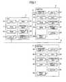
- FIG. 1is a block diagram showing the hardware structure of a system including a personal computer for executing a virtual device renaming program according to a preferred embodiment of the present invention, and printers;
- FIG. 2is a flowchart illustrating steps in the virtual device renaming program according to the preferred embodiment of the present invention
- FIG. 3is a table listing the names and status of virtual devices according to the preferred embodiment of the present invention.
- FIG. 4is a table listing the status of the virtual devices and the corresponding numerals added to the names of the virtual devices according to the preferred embodiment of the present invention
- FIG. 5is a table listing the original names and modified names of the virtual devices according to the preferred embodiment of the present invention.
- FIG. 6is an explanatory diagram showing a Print dialog box according to the preferred embodiment of the present invention.
- FIG. 7is an explanatory diagram showing the Print dialog box when a list box has been opened therein according to the preferred embodiment of the present invention.
- FIG. 1is a block diagram showing the general structure of a system including a personal computer 1 .
- the personal computer 1functions as a data processing device for executing processes corresponding to the virtual device renaming program according to the preferred embodiment.
- the personal computer 1can communicate with a plurality of printers.
- FIG. 1shows two printers 2 and 3 that are connected to the personal computer 1 in different ways. Specifically, the printer 2 is directly connected to the personal computer 1 through a printer cable 4 as a local printer, while the printer 3 communicates with the personal computer 1 through a LAN cable 5 as a network printer.
- the personal computer 1can also communicate with printers other than the printers 2 and 3 . However, such printers are not shown in FIG. 1 since the connection configurations are identical to those used for the printers 2 and 3 . In a process for renaming virtual device described later, the personal computer 1 will be capable of using five printers, with five virtual devices corresponding to five printers registered in the personal computer 1 .
- the personal computer 1 in the system described aboveincludes a CPU 10 , a ROM 11 , a RAM 12 , a hard disk drive 13 , a control unit 14 , a display unit 15 , a printer port interface 16 , and a LAN (local area network) interface 17 .
- the CPU 10executes various calculations and processes for controlling components in the personal computer 1 according to programs stored in the ROM 11 and RAM 12 .
- the CPU 10also executes a process for renaming virtual device described later.
- the ROM 11is a storage device capable of saving stored contents when a power switch of the personal computer 1 is turned off.
- the ROM 11stores BIOS (Basic Input/Output System) data and other read-only data that is normally not updated.
- BIOSBasic Input/Output System
- the RAM 12is a storage device employed as a main memory or the like directly accessed by the CPU 10 . Operating system, applications programs, and the like are read into the RAM 12 from the hard disk drive 13 .
- the RAM 12also stores results of computations performed by the CPU 10 and data read from the hard disk drive 13 .
- the CPU 10When executing the process to rename virtual device described later, the CPU 10 reads a virtual device renaming program into the RAM 12 from the hard disk drive 13 and executes the process for renaming virtual device based on the virtual device renaming program stored in the RAM 12 .
- the hard disk drive 13functions to save the operating system, various application programs, and various data files, as well as the virtual device renaming program mentioned above.
- the control unit 14is an input device for inputting various user instructions.
- the control unit 14is configured of a keyboard and various pointing devices, such as a mouse.
- the display unit 15is an output device for presenting various data to the user.
- the display unit 15may be configured of a liquid crystal display capable of displaying color images.
- the printer port interface 16is an interface capable of connecting with a printer.
- the printer port interface 16may be configured of a serial interface such as a USB (Universal Serial Bus) interface, or a parallel interface such as an IEEE 1284 interface.
- a serial interfacesuch as a USB (Universal Serial Bus) interface
- a parallel interfacesuch as an IEEE 1284 interface.
- the LAN interface 17is an interface for communicating with printers or other peripheral devices on a network via a LAN cable.
- Windowsregistered trademark
- Windowsis installed on the personal computer 1 as the operating system. Since the various functions of the Windows operating system are well known in the art, a detailed description of these functions will not be described herein. However, the following description presupposes that the personal computer 1 possesses the various functions provided by Windows.
- the printer 2includes a CPU 20 , a ROM 21 , a RAM 22 , a hard disk drive 23 , operating keys 24 , a display panel 25 , a printer port interface 26 , a LAN interface 27 , a nonvolatile RAM 28 , and a print unit 29 .
- the CPU 20executes various calculations and control processes for controlling components in the printer 2 according to control programs stored in the ROM 21 .
- the ROM 21is a storage device capable of saving stored contents when a power switch of the printer 2 is switched off. In addition to the control programs mentioned above, the ROM 21 stores various read-only data that is normally not updated.
- the RAM 22is a storage device employed as the main memory or the like directly accessed by the CPU 20 . Various data generated through computations by the CPU 20 are temporarily stored in the RAM 22 .
- the hard disk drive 23is a storage device for storing a large volume of data that cannot be stored in the RAM 22 .
- the operating keys 24are input devices that the user operates manually to issue instructions to the printer 2 .
- the display panel 25is configured of a small liquid crystal display that can display settings and status of the printer 2 and other data.
- the printer port interface 26is capable of connecting with a personal computer and has the same standard as the printer port interface 16 of the personal computer 1 .
- the printer port interface 26may be configured of a serial interface such as the USB interface, or a parallel interface such as the IEEE 1284 interface.
- the LAN interface 27is an interface for communicating with a personal computer on a network via a LAN cable.
- the nonvolatile RAM 28is a storage device for storing variable settings related to the printer 2 and other data that is preferably not lost when the power to the printer 2 is switched off.
- the print unit 29is configured of a conveying mechanism for conveying a sheet-like medium such as a recording paper from a feeding section to a discharging section, a recording mechanism for recording images on the medium while the conveying mechanism conveys the medium along a conveying path, and the like.
- the printer 3includes a CPU 30 , a ROM 31 , a RAM 32 , a hard disk drive 33 , operating keys 34 , a display panel 35 , a printer port interface 36 , a LAN interface 37 , a nonvolatile RAM 38 , and a print unit 39 .
- the components constituting the printer 3are identical to those in the printer 2 and, hence, a description of these components will not be repeated.
- the following descriptionaddresses a case in which five virtual devices shown in FIG. 3 have been installed in the personal computer 1 . That is, the personal computer 1 is capable of using five printers.
- the name of the printer driver, the name of a file storing the printer driver program, and the likeare registered in a registry (storage area managed by the operating system) of the personal computer 1 .
- This processis equivalent to installing a virtual device on the personal computer 1 .
- an application programoutputs print data
- the usercan specify a virtual device registered in the personal computer 1 as the output destination in order to output the print data to the printer corresponding to that virtual device.
- the userviews names of the virtual devices and selects a desired device.
- the names of the virtual devices viewed by the userare the names of printer drivers registered in the registry.
- the status of the five virtual devices(that is, the status of printers corresponding to these virtual devices) will be treated as that shown in FIG. 3 .
- the CPU 10At the beginning of the process for renaming virtual device in S 201 , the CPU 10 first initializes a counter i to 1. In S 202 the CPU 10 determines whether i is greater than the number of virtual devices. Since there are five virtual devices in the example of the preferred embodiment, in the process of S 202 the CPU 10 compares the value stored in the counter i to 5. At this point of the description, the counter i has just been initialized in the process of S 201 and, therefore, is not greater than 5 (S 202 : NO). In this case, the CPU 10 advances to S 203 .
- the CPU 10determines whether the status of the i th virtual device shown in FIG. 3 has changed.
- any methodmay be used in S 203 to extract the status of the virtual device.
- the CPU 10may activate a resident process for acquiring data indicating the status of the virtual device from the printer corresponding to that virtual device and may acquire the status of the virtual device in S 202 by the inter-process communication.
- the resident processmay be configured to write data corresponding to the status of the virtual device to a file each time the data is acquired from the printer, enabling the CPU 10 to read the data from this file.
- the CPU 10may directly acquire data from the printer corresponding to the virtual device in S 203 by executing a process similar to the resident process.
- a suitable method of acquiring the status of virtual devicesmay be selected from these methods with consideration for the system scale, processing rate, convenience, required costs, and the like.
- the CPU 10sets the i th virtual device shown in FIG. 3 as the target virtual device and initializes the device name of the target virtual device to the original virtual device name. For example, if the value stored in the counter i is 2, then the virtual device name after initialization is “YYYY4800CX.”
- the CPU 10adds a symbol to the head of the virtual device name indicating the status of the i th virtual device.
- the symbol added to the head of the virtual device nameis determined from a table, such as that shown in FIG. 4 , stored in the registry of the personal computer 1 .
- Each symbolincludes two digits that indicate the status of the device. A “0” or a “5” in the leading digit indicates a normal status, while a “9” indicates an abnormal status. While indicating a normal status, a “5” in the first digit also indicates a caution state. If the leading digit is a “5” or a “9”, the second digit is modified according to the cause of the caution state or abnormal state, and a character string describing this cause (such as “paper low”) is also included in the name.
- One of the symbols described aboveis attached to the head of the virtual device name based on the status of the i th virtual device.
- the names of each virtual device in the states shown in FIG. 3are changed to the “modified virtual device name” shown in FIG. 5 .
- the modified virtual device name of the second virtual deviceis set to “90 out-of-paper-YYYY4800CX.”
- the CPU 10advances to S 206 after completing the process in S 205 , or by skipping the processes in S 204 and S 205 when the status of the i th virtual device has not changed (S 203 : NO).
- S 206the CPU 10 increments the counter i by 1 and subsequently returns to S 202 .
- the counter iis now greater than the number of virtual devices (S 202 : YES), indicating that the process has been completed for all virtual devices. Accordingly, the CPU 10 returns to S 201 .
- the CPU 10performs the loop process of S 202 -S 206 again from the beginning, monitoring changes in the status of the virtual devices in S 203 .
- the CPU 10executes the processes in S 204 and S 205 when a change in status occurs.
- the names of the virtual devices registered in the personal computer 1are modified as shown in FIG. 5 .
- the “modified virtual device names” shown in FIG. 5are displayed when prompting the user to select a virtual device.
- a Print dialog box 51such as that shown in FIG. 6
- a list box 53is provided in the Print dialog box 51 for allowing the user to select a desired virtual device.
- the Print dialog box 51is first displayed, the currently selected virtual device name is displayed in the list box 53 .
- the userIf the user wishes to select a different virtual device, the user operates a pointing device to click on the mark on the right end of the list box 53 (or performs keyboard operations or the like set as an equivalent function). This operation displays a list 55 near the list box 53 (directly below the list box 53 in the present example), as shown in FIG. 7 .
- the list 55includes a list of names for a plurality of alternative virtual devices.
- the virtual device namesare ordered by character code according to the specifications of the Windows OS.
- the virtual device nameshave been modified by adding the symbol shown in FIG. 4 to the head of the original virtual device name.
- the names of properly working virtual devicesare arranged in the top of the list 55 shown in FIG. 7 due to the “00” added to the head of the name.
- the names of properly working virtual devicesare followed by names of virtual devices in a caution state to the head of which has been added “5x” (where x is either 0 or 1), and subsequently by names of virtual devices in an abnormal state to the head of which names has been added “9x” (where x is an integer between 0 and 3).
- xis an integer between 0 and 3
- the personal computer 1executes a process to rename the virtual devices, modifying the names of the devices according to their status. Hence, when the personal computer 1 displays a plurality of names of virtual devices for the user, the user can select a virtual device in a desired state by referencing the list of names.
- the userselects a virtual device in a state capable of printing by viewing the list of virtual device names, even when the list of virtual devices includes devices that are incapable of printing.
- both numerals representing the status of the virtual device and a character string representing the status of the virtual deviceare included in the modified virtual device name, the user can learn the status of the virtual device by looking at either the numerals or the character string.
- the numerals representing the status of the virtual deviceare added at the head of the device name, the modified names of virtual devices are displayed in an order that groups virtual devices of the same state together. Therefore, the user can more easily find a section of the display including a group of virtual devices of the desired status than when virtual devices of various statuses are mixed in the display, aiding the user in selecting a virtual device in the desired state.
- the numerals representing the status of the virtual deviceare set smaller as the device nears a normal status.
- the personal computer 1displays the virtual device names in order of their character codes according to the function of the operating system, virtual devices in a normal state are listed at the top, while virtual devices in an abnormal state are listed on the bottom. Accordingly, unlike the method of simply displaying virtual devices of the same status together, this method enables the user to select virtual devices in a normal state more easily by browsing virtual device names at the top of the list.
- the numerals representing the status of the virtual devicesare set so that the user can distinguish whether the virtual device is operating normally or abnormally, and whether the virtual device is in a caution state if operating normally, simply by viewing the first digit. Therefore, when viewing the virtual device names, the user can learn whether the status of the virtual device is normal or abnormal and, when normal, whether the virtual device is in a caution state.
- the personal computer 1can modify the virtual device name if the status of at least one virtual device changes, modifying the virtual device name to a name reflecting the new status.
- modified virtual device names in the preferred embodimentare configured by adding both a numeral representing the status of the virtual device (00, 50, 51, 90, 91, 92, and 93) and a character string representing the status of the virtual device (normal, paper low, toner low, out-of-paper, out-of-toner, power off, and off-line), it is possible to add only one of these instead.
- a character string representing the status of the virtual devicesuch as a normal, paper low, toner low, out-of-paper, out-of-toner, power off, and off-line status.
- a character string representing the status of the virtual devicesuch as a normal, paper low, toner low, out-of-paper, out-of-toner, power off, and off-line status.
- adding the numerals to the head of the virtual device namesensures that the virtual device names are arranged in a desired order, while adding a character string directly after the numerals indicates the status of the virtual device more clearly than the numerals, thereby optimizing the order and improving understanding.
- a character string representing the status of the virtual deviceafter the original virtual device name when the numerals are added to the head of the name for arranging the virtual device names in a desired order. Adding the character string to the end of the virtual device name has no particular effect on the order. If the user does not care about the order in which the virtual device names are displayed, the numerals and character strings representing the status of the virtual devices may be added anywhere in the name. In this case, the user can still determine the status of a virtual device simply by referring to the virtual device name.
- the preferred embodimentuses the two-digit numerals shown in the example of FIG. 4 as a character string attached to the head of the virtual device names.
- the correlation between character strings including such numerals (or letters or symbols in place of the numerals) and the status of the virtual devicesmay be predetermined and unchangeable or may be variable, allowing the user to modify the correlations as desired.
- the usercan adjust the priority for displaying virtual device names to a desired order.
- a usercan place emphasis on displaying virtual devices that are out of paper by associating smaller numerals (hereinafter, smaller numerals may also indicate letters or symbols having a lower character code) to the out-of-paper status, and can place priority on displaying virtual devices in the power off state by associating smaller numerals with the power off status, thereby displaying virtual device names in an order that is most convenient for each user.
- smaller numeralsmay also indicate letters or symbols having a lower character code
- virtual devicesare broadly divided into three groups, i.e., virtual devices operating normally and not in a caution state, virtual devices operating normally in a caution state, and virtual devices operating abnormally, by using the numerals “0”, “5”, and “9” in the first digit of the character array added to the head of the virtual device name.
- these groupscan be divided using characters other than “0”, “5”, and “9”.
- characters other than numeralssuch as “A”, “B”, and “C”.
- the portion of the character string corresponding to “0”, “5”, and “9”may be configured of two or more characters from a functional perspective.
- the first two characters of the character stringmay be set to “0A” when the status of the virtual device is normal with no caution, “0B” when the status is normal with caution, and “1C” when the status is abnormal.
- “0A” and “0B”are sorted according to the second character, while “1C” is sorted with respect to “0A” and “0B” according to the first character.
- This methodapplies the order “0A”, “0B”, and “1C” to the virtual device names, similar to the order “0”, “5”, and “9” described above.
Landscapes
- Engineering & Computer Science (AREA)
- Theoretical Computer Science (AREA)
- Human Computer Interaction (AREA)
- Physics & Mathematics (AREA)
- General Engineering & Computer Science (AREA)
- General Physics & Mathematics (AREA)
- Accessory Devices And Overall Control Thereof (AREA)
- Computer And Data Communications (AREA)
- Information Retrieval, Db Structures And Fs Structures Therefor (AREA)
- User Interface Of Digital Computer (AREA)
Abstract
Description
Claims (12)
Applications Claiming Priority (2)
| Application Number | Priority Date | Filing Date | Title |
|---|---|---|---|
| JP2006021202AJP4916729B2 (en) | 2006-01-30 | 2006-01-30 | Virtual device name change program |
| JP2006-021202 | 2006-01-30 |
Publications (2)
| Publication Number | Publication Date |
|---|---|
| US20070177198A1 US20070177198A1 (en) | 2007-08-02 |
| US8051434B2true US8051434B2 (en) | 2011-11-01 |
Family
ID=37982460
Family Applications (1)
| Application Number | Title | Priority Date | Filing Date |
|---|---|---|---|
| US11/627,020Expired - Fee RelatedUS8051434B2 (en) | 2006-01-30 | 2007-01-25 | Data processing device for renaming virtual device |
Country Status (4)
| Country | Link |
|---|---|
| US (1) | US8051434B2 (en) |
| EP (1) | EP1818806B1 (en) |
| JP (1) | JP4916729B2 (en) |
| CN (1) | CN100589071C (en) |
Cited By (1)
| Publication number | Priority date | Publication date | Assignee | Title |
|---|---|---|---|---|
| US20140196034A1 (en)* | 2012-02-22 | 2014-07-10 | Panasonic Corporation | Virtual machine control apparatus and virtual machine control method |
Families Citing this family (19)
| Publication number | Priority date | Publication date | Assignee | Title |
|---|---|---|---|---|
| JP4696938B2 (en) | 2006-01-30 | 2011-06-08 | ブラザー工業株式会社 | Virtual device name change program |
| JP4337824B2 (en) | 2006-01-30 | 2009-09-30 | ブラザー工業株式会社 | Virtual device name change program |
| US9224073B2 (en)* | 2007-03-28 | 2015-12-29 | Brother Kogyo Kabushiki Kaisha | Data processor saving data indicating progress status of printing process retrievable by client |
| JP5488341B2 (en)* | 2010-08-26 | 2014-05-14 | ブラザー工業株式会社 | Device, help server, and program |
| US9135037B1 (en) | 2011-01-13 | 2015-09-15 | Google Inc. | Virtual network protocol |
| US8874888B1 (en) | 2011-01-13 | 2014-10-28 | Google Inc. | Managed boot in a cloud system |
| US9237087B1 (en) | 2011-03-16 | 2016-01-12 | Google Inc. | Virtual machine name resolution |
| US9063818B1 (en) | 2011-03-16 | 2015-06-23 | Google Inc. | Automated software updating based on prior activity |
| US8533796B1 (en) | 2011-03-16 | 2013-09-10 | Google Inc. | Providing application programs with access to secured resources |
| US9075979B1 (en) | 2011-08-11 | 2015-07-07 | Google Inc. | Authentication based on proximity to mobile device |
| US8966198B1 (en) | 2011-09-01 | 2015-02-24 | Google Inc. | Providing snapshots of virtual storage devices |
| US20130135674A1 (en)* | 2011-11-29 | 2013-05-30 | Toshiba Tec Kabushiki Kaisha | Network connectable device and method of changing device's own name |
| US8958293B1 (en)* | 2011-12-06 | 2015-02-17 | Google Inc. | Transparent load-balancing for cloud computing services |
| US8800009B1 (en) | 2011-12-30 | 2014-08-05 | Google Inc. | Virtual machine service access |
| US8983860B1 (en) | 2012-01-30 | 2015-03-17 | Google Inc. | Advertising auction system |
| US8996887B2 (en) | 2012-02-24 | 2015-03-31 | Google Inc. | Log structured volume encryption for virtual machines |
| US8677449B1 (en) | 2012-03-19 | 2014-03-18 | Google Inc. | Exposing data to virtual machines |
| US9069806B2 (en) | 2012-03-27 | 2015-06-30 | Google Inc. | Virtual block devices |
| JP6387752B2 (en)* | 2014-09-04 | 2018-09-12 | 富士ゼロックス株式会社 | Printer control device, printer control program |
Citations (30)
| Publication number | Priority date | Publication date | Assignee | Title |
|---|---|---|---|---|
| US5353399A (en) | 1989-11-08 | 1994-10-04 | Hitachi, Ltd. | Method and system for selecting devices in information networks, including inputting/outputting data to a specified device selected by pointing to a corresponding indicator on a screen |
| JPH07152507A (en) | 1993-10-27 | 1995-06-16 | Fuji Xerox Co Ltd | Print instructing system and its method |
| JPH096557A (en) | 1995-04-04 | 1997-01-10 | Fuji Xerox Co Ltd | Printing instructing device |
| JPH096558A (en) | 1995-06-16 | 1997-01-10 | Fuji Xerox Co Ltd | Printer control device |
| US5845078A (en)* | 1992-04-16 | 1998-12-01 | Hitachi, Ltd. | Network integrated construction system, method of installing network connection machines, and method of setting network parameters |
| US5996029A (en)* | 1993-01-18 | 1999-11-30 | Canon Kabushiki Kaisha | Information input/output control apparatus and method for indicating which of at least one information terminal device is able to execute a functional operation based on environmental information |
| JP2000076032A (en) | 1998-08-31 | 2000-03-14 | Ricoh Co Ltd | State access system |
| JP2000293336A (en) | 1999-04-07 | 2000-10-20 | Canon Inc | Printing device status display control device, control method of printing device status display control device, and storage medium storing computer-readable program |
| US6177934B1 (en)* | 1993-01-18 | 2001-01-23 | Canon Kabushiki Kaisha | Server device and image processing device |
| US6184998B1 (en)* | 1997-09-15 | 2001-02-06 | Canon Kabushiki Kaisha | Adding printing to the windows registry |
| JP2001056756A (en) | 1999-08-19 | 2001-02-27 | Oki Data Corp | Network printing system |
| JP2001282661A (en) | 2000-03-31 | 2001-10-12 | Sharp Corp | Peripheral device setting device, peripheral device setting method, and computer-readable recording medium recording peripheral device setting program |
| JP2001306279A (en) | 2000-04-27 | 2001-11-02 | Seiko Epson Corp | Computer readable recording medium |
| US6473811B1 (en)* | 1998-03-13 | 2002-10-29 | Canon Kabushiki Kaisha | Method and apparatus for displaying a connection status of a device based on connection information |
| US20030066027A1 (en)* | 2001-09-14 | 2003-04-03 | Canon Kabushiki Kaisha | Information processing apparatus and method |
| JP2003271286A (en) | 2002-03-12 | 2003-09-26 | Ricoh Co Ltd | Printer driver and recording medium recording printer driver |
| US20040051743A1 (en) | 2002-09-13 | 2004-03-18 | Fuji Xerox Co., Ltd. | Printer icon generating system |
| US6798530B1 (en) | 1999-12-07 | 2004-09-28 | Xerox Corporation | Systems, methods and graphical user interfaces for printing object optimized images using virtual printers |
| US20040230966A1 (en) | 2003-05-12 | 2004-11-18 | Morris Robert P. | User-defined templates for automatic image naming |
| US20040227973A1 (en) | 2002-04-04 | 2004-11-18 | Taylor Jarrett D. | System and method for distributing printer properties on a computer network |
| JP2005085132A (en) | 2003-09-10 | 2005-03-31 | Canon Inc | Information processing apparatus, information processing method, information processing program, and computer-readable storage medium |
| US20050206938A1 (en) | 2004-03-22 | 2005-09-22 | Fuji Xerox Co., Ltd. | Printer management method, printer management apparatus, and program for printer management |
| JP2006011831A (en) | 2004-06-25 | 2006-01-12 | Canon Sales Co Inc | Print controller, method for setting virtual printer, program, and recording medium |
| US20060200644A1 (en) | 2005-03-04 | 2006-09-07 | Fuji Xerox Co., Ltd. | Storage medium for storing processing mode specifying information conversion program and processing mode specifying information conversion method |
| US20060206903A1 (en) | 2005-03-10 | 2006-09-14 | Microsoft Corporation | System data interfaces, related architectures, print system data interfaces and related print system architectures |
| US7231435B2 (en)* | 2001-10-29 | 2007-06-12 | Canon Kabushiki Kaisha | Network system, information processing apparatus, information processing method, and control program |
| US20070177202A1 (en) | 2006-01-30 | 2007-08-02 | Brother Kogyo Kabushiki Kaisha | Data Processing Device for Renaming Virtual Device |
| US20070177178A1 (en) | 2006-01-30 | 2007-08-02 | Brother Kogyo Kabushiki Kaisha | Data Processing Device for Renaming Virtual Device |
| US7287253B2 (en) | 2002-07-26 | 2007-10-23 | Canon Kabushiki Kaisha | Installation of device software and formulation of unique identification information based on time information |
| US7310690B2 (en)* | 2002-04-11 | 2007-12-18 | Canon Kabushiki Kaisha | Communication device selecting its own unique name by comparing with other names from other communication devices on a network |
- 2006
- 2006-01-30JPJP2006021202Apatent/JP4916729B2/ennot_activeExpired - Fee Related
- 2007
- 2007-01-25USUS11/627,020patent/US8051434B2/ennot_activeExpired - Fee Related
- 2007-01-25EPEP07250309.7Apatent/EP1818806B1/ennot_activeCeased
- 2007-01-30CNCN200710006210Apatent/CN100589071C/ennot_activeExpired - Fee Related
Patent Citations (35)
| Publication number | Priority date | Publication date | Assignee | Title |
|---|---|---|---|---|
| US5353399A (en) | 1989-11-08 | 1994-10-04 | Hitachi, Ltd. | Method and system for selecting devices in information networks, including inputting/outputting data to a specified device selected by pointing to a corresponding indicator on a screen |
| US5845078A (en)* | 1992-04-16 | 1998-12-01 | Hitachi, Ltd. | Network integrated construction system, method of installing network connection machines, and method of setting network parameters |
| US5996029A (en)* | 1993-01-18 | 1999-11-30 | Canon Kabushiki Kaisha | Information input/output control apparatus and method for indicating which of at least one information terminal device is able to execute a functional operation based on environmental information |
| US6177934B1 (en)* | 1993-01-18 | 2001-01-23 | Canon Kabushiki Kaisha | Server device and image processing device |
| JPH07152507A (en) | 1993-10-27 | 1995-06-16 | Fuji Xerox Co Ltd | Print instructing system and its method |
| JPH096557A (en) | 1995-04-04 | 1997-01-10 | Fuji Xerox Co Ltd | Printing instructing device |
| JPH096558A (en) | 1995-06-16 | 1997-01-10 | Fuji Xerox Co Ltd | Printer control device |
| US6184998B1 (en)* | 1997-09-15 | 2001-02-06 | Canon Kabushiki Kaisha | Adding printing to the windows registry |
| US6473811B1 (en)* | 1998-03-13 | 2002-10-29 | Canon Kabushiki Kaisha | Method and apparatus for displaying a connection status of a device based on connection information |
| JP2000076032A (en) | 1998-08-31 | 2000-03-14 | Ricoh Co Ltd | State access system |
| JP2000293336A (en) | 1999-04-07 | 2000-10-20 | Canon Inc | Printing device status display control device, control method of printing device status display control device, and storage medium storing computer-readable program |
| JP2001056756A (en) | 1999-08-19 | 2001-02-27 | Oki Data Corp | Network printing system |
| US6798530B1 (en) | 1999-12-07 | 2004-09-28 | Xerox Corporation | Systems, methods and graphical user interfaces for printing object optimized images using virtual printers |
| JP2001282661A (en) | 2000-03-31 | 2001-10-12 | Sharp Corp | Peripheral device setting device, peripheral device setting method, and computer-readable recording medium recording peripheral device setting program |
| JP2001306279A (en) | 2000-04-27 | 2001-11-02 | Seiko Epson Corp | Computer readable recording medium |
| US20030066027A1 (en)* | 2001-09-14 | 2003-04-03 | Canon Kabushiki Kaisha | Information processing apparatus and method |
| US7231435B2 (en)* | 2001-10-29 | 2007-06-12 | Canon Kabushiki Kaisha | Network system, information processing apparatus, information processing method, and control program |
| JP2003271286A (en) | 2002-03-12 | 2003-09-26 | Ricoh Co Ltd | Printer driver and recording medium recording printer driver |
| US20040227973A1 (en) | 2002-04-04 | 2004-11-18 | Taylor Jarrett D. | System and method for distributing printer properties on a computer network |
| US7310690B2 (en)* | 2002-04-11 | 2007-12-18 | Canon Kabushiki Kaisha | Communication device selecting its own unique name by comparing with other names from other communication devices on a network |
| US7779168B2 (en) | 2002-07-26 | 2010-08-17 | Canon Kabushiki Kaisha | Information processing apparatus, information processing method, and computer-readable memory medium storing program for realizing the method |
| US7287253B2 (en) | 2002-07-26 | 2007-10-23 | Canon Kabushiki Kaisha | Installation of device software and formulation of unique identification information based on time information |
| US20040051743A1 (en) | 2002-09-13 | 2004-03-18 | Fuji Xerox Co., Ltd. | Printer icon generating system |
| JP2004110127A (en) | 2002-09-13 | 2004-04-08 | Fuji Xerox Co Ltd | Printer icon generation device, printer icon generation method, and program |
| US20040230966A1 (en) | 2003-05-12 | 2004-11-18 | Morris Robert P. | User-defined templates for automatic image naming |
| JP2005085132A (en) | 2003-09-10 | 2005-03-31 | Canon Inc | Information processing apparatus, information processing method, information processing program, and computer-readable storage medium |
| JP2005267544A (en) | 2004-03-22 | 2005-09-29 | Fuji Xerox Co Ltd | Printer managing method and device, and program |
| US20050206938A1 (en) | 2004-03-22 | 2005-09-22 | Fuji Xerox Co., Ltd. | Printer management method, printer management apparatus, and program for printer management |
| JP2006011831A (en) | 2004-06-25 | 2006-01-12 | Canon Sales Co Inc | Print controller, method for setting virtual printer, program, and recording medium |
| US20060200644A1 (en) | 2005-03-04 | 2006-09-07 | Fuji Xerox Co., Ltd. | Storage medium for storing processing mode specifying information conversion program and processing mode specifying information conversion method |
| US20060206903A1 (en) | 2005-03-10 | 2006-09-14 | Microsoft Corporation | System data interfaces, related architectures, print system data interfaces and related print system architectures |
| US20070177202A1 (en) | 2006-01-30 | 2007-08-02 | Brother Kogyo Kabushiki Kaisha | Data Processing Device for Renaming Virtual Device |
| US20070177178A1 (en) | 2006-01-30 | 2007-08-02 | Brother Kogyo Kabushiki Kaisha | Data Processing Device for Renaming Virtual Device |
| JP2007200253A (en) | 2006-01-30 | 2007-08-09 | Brother Ind Ltd | Virtual device name change program |
| JP2007200255A (en) | 2006-01-30 | 2007-08-09 | Brother Ind Ltd | Virtual device name change program |
Non-Patent Citations (5)
| Title |
|---|
| Decision of Rejection mailed Oct. 19, 2010 in Japanese Application No. 2006-021202 and English translation thereof. |
| EP Search Report dtd Feb. 19, 2008, EP App. 07250309-7. |
| Extended European Search Report dated Mar. 4, 2008, EP Appln. No. 07250297.4. |
| JP Office Action dated Mar. 16, 2010, Japanese Appln. No. 2006-021203, English translation. |
| JP Office Action dtd Mar. 23, 2010, JP Appln. 2006-021202, English translation. |
Cited By (2)
| Publication number | Priority date | Publication date | Assignee | Title |
|---|---|---|---|---|
| US20140196034A1 (en)* | 2012-02-22 | 2014-07-10 | Panasonic Corporation | Virtual machine control apparatus and virtual machine control method |
| US9170832B2 (en)* | 2012-02-22 | 2015-10-27 | Panasonic Intellectual Property Corporation Of America | Virtual machine control apparatus and virtual machine control method |
Also Published As
| Publication number | Publication date |
|---|---|
| EP1818806A2 (en) | 2007-08-15 |
| JP4916729B2 (en) | 2012-04-18 |
| JP2007200254A (en) | 2007-08-09 |
| EP1818806B1 (en) | 2018-03-07 |
| EP1818806A3 (en) | 2008-03-19 |
| CN101013355A (en) | 2007-08-08 |
| US20070177198A1 (en) | 2007-08-02 |
| CN100589071C (en) | 2010-02-10 |
Similar Documents
| Publication | Publication Date | Title |
|---|---|---|
| US8051434B2 (en) | Data processing device for renaming virtual device | |
| US6562078B1 (en) | Arrangement and method for inputting non-alphabetic language | |
| US8171180B2 (en) | Information processing apparatus, information processing system, and recording medium | |
| US8661235B2 (en) | Firmware storage medium with customized image | |
| US8020175B2 (en) | Data processing device for renaming virtual device | |
| US8031353B2 (en) | Data processing device for renaming virtual device | |
| US20090109473A1 (en) | Information processing device, information processing method, and computer-readable storage medium | |
| JP2005504370A5 (en) | ||
| US20070067740A1 (en) | Driver to configure a user interface and method thereof | |
| JP2007272857A (en) | Device driver system | |
| US20160054956A1 (en) | Computer-readable recording medium, configuration presentation method, and configuration presentation device | |
| JP4007746B2 (en) | Peripheral device setting device, peripheral device setting method, and computer-readable recording medium recording peripheral device setting program | |
| US20020101406A1 (en) | Touch-controlled hot key device | |
| JP2003177854A (en) | Experience level picture display program and device | |
| JP2004310154A (en) | Computer program, peripheral device, and application program | |
| US20120110506A1 (en) | System and Method for File Navigation | |
| JP5870783B2 (en) | Image forming system, information device, image forming apparatus, computer program, and document printing method | |
| US20060069908A1 (en) | Information processing apparatus and boot control method | |
| JP2004110739A (en) | Print instruction device and print instruction method | |
| US20210081155A1 (en) | Information processing method, printing method and non-temporary recording medium | |
| US20080278742A1 (en) | System and method for customized routing of document data intercepted through port redirection | |
| KR0149757B1 (en) | Self-contained printer and its control method | |
| KR20070064195A (en) | How to print a document to be printed together with related documents, and the host and printer used therein | |
| CN117270702A (en) | Candidate word screen-surfing method and device, electronic equipment and readable storage medium | |
| KR100433426B1 (en) | Printer having function for making document and control method thereof |
Legal Events
| Date | Code | Title | Description |
|---|---|---|---|
| AS | Assignment | Owner name:BROTHER KOGYO KABUSHIKI KAISHA, JAPAN Free format text:ASSIGNMENT OF ASSIGNORS INTEREST;ASSIGNOR:MIYATA, YUJI;REEL/FRAME:018804/0200 Effective date:20070119 | |
| ZAAA | Notice of allowance and fees due | Free format text:ORIGINAL CODE: NOA | |
| ZAAB | Notice of allowance mailed | Free format text:ORIGINAL CODE: MN/=. | |
| ZAAA | Notice of allowance and fees due | Free format text:ORIGINAL CODE: NOA | |
| ZAAB | Notice of allowance mailed | Free format text:ORIGINAL CODE: MN/=. | |
| STCF | Information on status: patent grant | Free format text:PATENTED CASE | |
| FPAY | Fee payment | Year of fee payment:4 | |
| MAFP | Maintenance fee payment | Free format text:PAYMENT OF MAINTENANCE FEE, 8TH YEAR, LARGE ENTITY (ORIGINAL EVENT CODE: M1552); ENTITY STATUS OF PATENT OWNER: LARGE ENTITY Year of fee payment:8 | |
| FEPP | Fee payment procedure | Free format text:MAINTENANCE FEE REMINDER MAILED (ORIGINAL EVENT CODE: REM.); ENTITY STATUS OF PATENT OWNER: LARGE ENTITY | |
| LAPS | Lapse for failure to pay maintenance fees | Free format text:PATENT EXPIRED FOR FAILURE TO PAY MAINTENANCE FEES (ORIGINAL EVENT CODE: EXP.); ENTITY STATUS OF PATENT OWNER: LARGE ENTITY | |
| STCH | Information on status: patent discontinuation | Free format text:PATENT EXPIRED DUE TO NONPAYMENT OF MAINTENANCE FEES UNDER 37 CFR 1.362 | |
| FP | Lapsed due to failure to pay maintenance fee | Effective date:20231101 |