US8049658B1 - Determination of the three-dimensional location of a target viewed by a camera - Google Patents
Determination of the three-dimensional location of a target viewed by a cameraDownload PDFInfo
- Publication number
- US8049658B1 US8049658B1US11/807,309US80730907AUS8049658B1US 8049658 B1US8049658 B1US 8049658B1US 80730907 AUS80730907 AUS 80730907AUS 8049658 B1US8049658 B1US 8049658B1
- Authority
- US
- United States
- Prior art keywords
- location
- camera
- azimuth
- interest
- radar
- Prior art date
- Legal status (The legal status is an assumption and is not a legal conclusion. Google has not performed a legal analysis and makes no representation as to the accuracy of the status listed.)
- Expired - Fee Related, expires
Links
- 238000000034methodMethods0.000claimsabstractdescription26
- 238000012545processingMethods0.000claimsdescription35
- 230000033001locomotionEffects0.000claimsdescription7
- 230000008569processEffects0.000abstractdescription5
- 238000011835investigationMethods0.000abstractdescription2
- 238000001514detection methodMethods0.000description5
- 238000010586diagramMethods0.000description4
- 241001465754MetazoaSpecies0.000description3
- 230000008901benefitEffects0.000description2
- 230000009545invasionEffects0.000description2
- 230000009471actionEffects0.000description1
- 238000013459approachMethods0.000description1
- 238000004364calculation methodMethods0.000description1
- 230000001276controlling effectEffects0.000description1
- 230000002596correlated effectEffects0.000description1
- 230000000875corresponding effectEffects0.000description1
- 230000001419dependent effectEffects0.000description1
- 238000009434installationMethods0.000description1
- 238000012423maintenanceMethods0.000description1
- 230000008520organizationEffects0.000description1
- 230000004044responseEffects0.000description1
Images


Classifications
- G—PHYSICS
- G01—MEASURING; TESTING
- G01S—RADIO DIRECTION-FINDING; RADIO NAVIGATION; DETERMINING DISTANCE OR VELOCITY BY USE OF RADIO WAVES; LOCATING OR PRESENCE-DETECTING BY USE OF THE REFLECTION OR RERADIATION OF RADIO WAVES; ANALOGOUS ARRANGEMENTS USING OTHER WAVES
- G01S5/00—Position-fixing by co-ordinating two or more direction or position line determinations; Position-fixing by co-ordinating two or more distance determinations
- G01S5/16—Position-fixing by co-ordinating two or more direction or position line determinations; Position-fixing by co-ordinating two or more distance determinations using electromagnetic waves other than radio waves
- G—PHYSICS
- G01—MEASURING; TESTING
- G01C—MEASURING DISTANCES, LEVELS OR BEARINGS; SURVEYING; NAVIGATION; GYROSCOPIC INSTRUMENTS; PHOTOGRAMMETRY OR VIDEOGRAMMETRY
- G01C21/00—Navigation; Navigational instruments not provided for in groups G01C1/00 - G01C19/00
- G01C21/005—Navigation; Navigational instruments not provided for in groups G01C1/00 - G01C19/00 with correlation of navigation data from several sources, e.g. map or contour matching
- G—PHYSICS
- G01—MEASURING; TESTING
- G01S—RADIO DIRECTION-FINDING; RADIO NAVIGATION; DETERMINING DISTANCE OR VELOCITY BY USE OF RADIO WAVES; LOCATING OR PRESENCE-DETECTING BY USE OF THE REFLECTION OR RERADIATION OF RADIO WAVES; ANALOGOUS ARRANGEMENTS USING OTHER WAVES
- G01S13/00—Systems using the reflection or reradiation of radio waves, e.g. radar systems; Analogous systems using reflection or reradiation of waves whose nature or wavelength is irrelevant or unspecified
- G01S13/66—Radar-tracking systems; Analogous systems
- G01S13/72—Radar-tracking systems; Analogous systems for two-dimensional tracking, e.g. combination of angle and range tracking, track-while-scan radar
- G01S13/723—Radar-tracking systems; Analogous systems for two-dimensional tracking, e.g. combination of angle and range tracking, track-while-scan radar by using numerical data
- G—PHYSICS
- G01—MEASURING; TESTING
- G01S—RADIO DIRECTION-FINDING; RADIO NAVIGATION; DETERMINING DISTANCE OR VELOCITY BY USE OF RADIO WAVES; LOCATING OR PRESENCE-DETECTING BY USE OF THE REFLECTION OR RERADIATION OF RADIO WAVES; ANALOGOUS ARRANGEMENTS USING OTHER WAVES
- G01S13/00—Systems using the reflection or reradiation of radio waves, e.g. radar systems; Analogous systems using reflection or reradiation of waves whose nature or wavelength is irrelevant or unspecified
- G01S13/86—Combinations of radar systems with non-radar systems, e.g. sonar, direction finder
- G01S13/867—Combination of radar systems with cameras
- G—PHYSICS
- G01—MEASURING; TESTING
- G01S—RADIO DIRECTION-FINDING; RADIO NAVIGATION; DETERMINING DISTANCE OR VELOCITY BY USE OF RADIO WAVES; LOCATING OR PRESENCE-DETECTING BY USE OF THE REFLECTION OR RERADIATION OF RADIO WAVES; ANALOGOUS ARRANGEMENTS USING OTHER WAVES
- G01S7/00—Details of systems according to groups G01S13/00, G01S15/00, G01S17/00
- G01S7/02—Details of systems according to groups G01S13/00, G01S15/00, G01S17/00 of systems according to group G01S13/00
- G01S7/04—Display arrangements
- G01S7/046—Display arrangements using an intermediate storage device, e.g. a recording/reproducing device
Definitions
- This inventionrelates to the determination of the three-dimensional location of a target in known terrain from sensed two-dimensional information.
- Homeland securityhas become of more than passing interest.
- One aspect of securityinvolves surveillance of regions near borders to be protected from invasion, whether the invasion is (a) by hostile troops seeking to enter and attack a region to be protected or'(b) by undocumented or criminal persons, as might occur at the U.S.-Mexican border.
- One of the problems with such surveillanceis that the regions under surveillance may be large, and the manpower available to perform the surveillance may be small.
- the availability of personnel to counter a detected incursionis a different issue. When the number of eyes available to perform surveillance or to survey is small, there is the possibility, or even the likelihood, that some incursions will not be noticed. Even when a large number of eyes is available, the relative infrequency of incursions may lead to momentary inattention, which again can lead to unnoticed incursions.
- ground proximity sensorsIn the region to be surveyed, and to radio to a human-attended center when movement is detected.
- One disadvantage of thisis that some of the sensors might have to be placed on the sovereign territory of another, which might not be possible.
- deploying such sensors over many miles along, and over suitable depth of, a borderwill be quite expensive. Not all the terrain to be protected will be amenable to use of a single type of proximity sensor, so multiple types might be required.
- such sensorshave the disadvantage that battery power would be required, and the changing of batteries in a large plurality of sensors scattered over a region in turn requires substantial manpower. Even if ground proximity sensors were to be deployed, they tend to be susceptible to false alarms such as animal movement (or even to movement of tree roots along the northern border). Historically, ground proximity sensors have been poor performers.
- a radar systemcan survey a region which includes sovereign territory of another, and can provide a current location and speed of an object, and the data can be stored to provide a track (history of locations).
- Ground Surveillance Radarhas a long history of use for surveillance, and so constitutes a mature technology. Some of these radars are easy to set up or install using trained personnel. Moving target detection for radar is well known, and can detect objects moving with some radial velocities relative to the radar.
- Ground surveillance radar (GSR)that is available for border surveillance provides a two-dimensional detection capability, which is to say that it only identifies the location of an object by range and azimuth.
- the GSRs available for border surveillancetend to have slow update rates (half a minute to more than a minute per scan), and also limitations in detection of objects with low radial velocity (relative to the radar location).
- the two dimensional object location, together with the slow update rate,make radar data somewhat difficult to use for the important task of cueing narrow field of view interrogation cameras to closely observe the target of interest.
- significant limitations to angular resolution and range accuracyresult in the detection mode of operation not being as effective as the tracking modes.
- Additional limitations of radar border surveillanceinclude possible inability to detect objects through vegetation and under various clutter conditions.
- a major disadvantage of radar systemsis that they cannot, in general, identify an object.
- a moving object smaller than a vehiclemight be a human intruder, or it might be an animal.
- a low-flying birdmight give rise to concern, since radar generally cannot determine the shape of an object. Radar systems undesirably tend to require skilled operators and maintenance personnel.
- Camerascan also be used for surveillance. Cameras, like radar systems, have the advantage of being able to extend their sensing capabilities across borders. As with GSR, cameras can be installed and set up by relatively unskilled personnel. They also cost less than radar systems. Cameras have the advantage of being capable of reporting the shape of an object within their fields of view, so can, in principle, tell the difference between an animal and a human.
- a video surveillance approachallows for use of infrared (IR) technology to detect warm bodies moving through vegetation and other similar obstructions, as the warm bodies provide enough of a difference between pixels for detection by video analytics.
- IRinfrared
- camerashave a problem similar to that of radar, in that they provide only a two-dimensional (azimuth and elevation) representation of a three-dimensional world.
- Another disadvantage of cameras for surveillance useis that the camera can only “see” objects which subtend a substantial portion of the field-of-view. That is, if the object is small and at a significant distance from the camera, its image may be so small as to be indistinguishable from the background. If a zoom lens function is directed toward the object so as to effectively enlarge the object in the field of view, the field of view is narrowed so that other targets or objects may be able to move through the region without being imaged.
- a method according town aspect of the inventionis for determining, in three dimensions, the location of a moving terrestrial or ground object observed in a region by a video camera.
- a terrain mapsupplies altitude for the latitude and longitude of each terrain point.
- the terrain informationis combined with camera location, field of view, and orientation to produce a computed terrain map relative to the camera.
- a video analytics stepprocesses the video and locates moving target(s) in two Cartesian coordinates.
- the coordinatesare processed with the camera information to produce target location in terms of azimuth and elevation angle.
- the computed map informationis combined with the angular target location to produce latitude, longitude, and altitude of the target.
- the target location informationis used for further investigation or to attack the target.
- a method for determining the third dimension of a 2-D radar trackto cue a camera or fuse with camera data.
- a methodis for determining the location of a moving object in a region of interest.
- the methodcomprises the steps of observing the region of interest with a camera to produce a frame-sequential video signal representing at least a part of the region of interest.
- Geospatial coordinates of the location of the camera, and information relating to the azimuth angle, elevation angle, and field of view of the cameraare provided.
- the video signalis applied to video analytics processing for detecting an object(s) which move(s) from frame to frame of the video signal, and for identifying the location in a two-dimensional Cartesian coordinate system of such an object.
- the location in a two-dimensional Cartesian coordinate system of an object which moves from frame to frame of the video signalis converted to a location expressed in terms of azimuth and elevation angle.
- a computed mapis provided that includes the altitudes of geospatial coordinate points, at least in the region of interest, together with computed range, azimuth, and elevation from the camera location to each computed map point.
- the computed map informationis processed together with the location of the object expressed in terms of azimuth and elevation angle and together with the location of the camera and information relating to the azimuth angle, elevation angle, and field of view of the camera, for producing information relating to the location of the moving object in three dimensions.
- the informationmay be in the form of longitude, latitude, and altitude.
- the three-dimensional location of the moving objectcan be displayed, or a zoom camera may be directed toward the location for better identification, or a weapon or surveillance device may be directed toward the location.
- the step of providing a computed map including the altitudes of geospatial coordinate points, at least in the region of interest, together with computed range, azimuth, and elevation from the camera location to each computed map pointcomprises the step of providing a terrain map including the altitudes of geospatial coordinate points, at least in the regions of interest. These geospatial coordinate points may be expressed in terms of longitude and latitude.
- the terrain map informationis processed together with the location of the camera and information relating to the azimuth angle, elevation angle, and field of view of the camera, to produce a computed map including latitude, longitude and altitude as a function of azimuth and elevation.
- a mode for performing close surveillance of a moving object in a region of interestcomprises the steps of additionally observing the region of interest with radar to produce a two-dimensional radar track (including at least range and azimuth) of an object in the region of interest, and providing geospatial coordinates of the location of the radar.
- This modeprovides a further map including the altitudes of geospatial coordinate points, at least in the region of interest, together with computed range, azimuth, and elevation from the radar location to each map point.
- the further mapis processed together with the location of the radar track in range and azimuth angle and also together with the location of the radar, for producing three-dimensional radar object location information.
- a camerais cued with the three dimensional radar object location information so as to observe the three dimension object location with the camera in order to further identify the target.
- An alternative mode according to this aspect of the inventionfor performing close surveillance of a moving object in a region of interest, comprises the steps of additionally observing the region of interest with radar to produce a two-dimensional radar track, including at least range and azimuth, of the object in the region of interest, and providing geospatial coordinates of the location of the radar.
- This alternative modealso includes the providing of a further map including the altitudes of geospatial coordinate points, at least in the region of interest, together with computed range, azimuth, and elevation from the radar location to each map point.
- the further mapis processed together with the location of the radar track in range and azimuth angle and together with the location of the radar, for producing three dimensional radar object location information.
- the processed three dimensional radar object locationis correlated to the processed three dimensional camera object location, and the information relating the object location, as generated by the radar and the camera, is fused to improve the accuracy of the object location.
- a surveillance craftis guided toward the three-dimensional location.
- the step of processing the terrain map together with the location of the object in azimuth and elevation angle together with the location of the camera and information relating to the azimuth angle, elevation angle, and field of view of the camera, for producing information relating to the location in three dimensions of the moving objectincludes the step of identifying a plurality of contiguous or juxtaposed azimuth-range cells covering the terrain points available from the terrain map, so that plural terrain points lie in each range cell.
- the range, azimuth and elevation relative to the camera locationare calculated for each terrain point.
- the azimuth-range cell in which the target is locatedis determined. That terrain point within that one of the azimuth-range cells which is closest to the target is identified. That terrain point within that one of the azimuth-range cells which is closest to the target is deemed to be the location of the target.
- FIG. 1 ais a simplified notional and block representation of a system including an aspect of the invention for using a camera to locate a target
- FIG. 1 bis a simplified notional representation similar to FIG. 1 a , in which the target location information is used to cue or control an adjustable camera initially used for locating the target to closely examine the target
- FIG. 1 cis a simplified notional and block diagram similar to FIGS. 1 a and 1 b , further including additional target location source or sources, together with a correlator to fuse the target location data
- FIG. 1 dis similar to FIGS. 1 a and 1 b , but further includes a source of radar data relating to the target, for controlling initial positioning of the target location camera
- FIG. 1 ais a simplified notional and block representation of a system including an aspect of the invention for using a camera to locate a target
- FIG. 1 bis a simplified notional representation similar to FIG. 1 a , in which the target location information is used to cue
- FIG. 1 eis a simplified notional and block diagram similar to FIG. 1 d , but using ground sensor information for initial positioning of the target location camera
- FIG. 1 fis similar to FIG. 1 d , but illustrates separate processors for performing processing for cueing the camera
- FIG. 1 gis similar to FIG. 1 b , but includes radar processors, an additional computed terrain map, and a further processor which correlates and fuses the information from the radar and from the camera;
- FIG. 2 ais a simplified logic flow chart or diagram of a portion of a control or processing system for determining the location of a target from computed terrain information and from information provided by a camera such as that of FIGS. 1 a , 1 b , 1 c , 1 d , 1 e , 1 f and/or 1 g , and FIGS. 2 b and 2 c are corresponding flow charts or diagrams of other portions of the control or processing system;
- FIG. 3is a simplified plot or plan view of terrain centered on a camera location, illustrating concentric range circles, angular sectors having magnitude dependent upon range, and specific terrain locations, some of which are illustrated as dots;
- FIG. 4is a simplified notional map useful in explaining cross-range.
- FIG. 5is a simplified elevation view of terrain similar to that of FIG. 1 , subdivided into a plurality of ranges, and showing why the closest range cell having certain properties is the location of a target.
- FIG. 1 arepresents a system 10 according to an aspect of the invention.
- the systemincludes a camera 12 with a lens 12 L mounted on a generally planar terrain region 16 p .
- the camera 12 with lens 12has an instantaneous field of view represented by lines 12 fv , which are illustrated as being centered on a field-of-view axis 12 vt (but do not necessarily have to be centered).
- the field of view 12 fvencompasses a region of interest 9 which includes a mound 16 m , a slope 16 s , and an intermediate region 16 i .
- Camera 12is associated with a cameral location device 14 , such as a global positioning system (GPS) receiver, which determines the camera location in terms of latitude, longitude, altitude, and heading, which aids in determining the camera pointing direction in terms of the field of view.
- GPSglobal positioning system
- the camera 12 location in terms of latitude, longitude, and altitudeis transmitted from camera location device 14 by way of a path 15 to a processor illustrated as a block 16 .
- Processor 16also receives information by way of a path 19 from a base terrain map illustrated as a block 18 .
- the information provided by base terrain map 18includes information about that portion of the region of interest 9 which is within the field-of-view 12 fv , and preferably also includes information about that portion of the region of interest 9 which might be viewed by camera 12 if the field of view or the direction of the camera changes.
- the information provided by base terrain map 18includes altitude for each map point (that is, altitude for each latitude/longitude pair).
- Processor 16uses the data from paths 15 and 19 to generate computed terrain data.
- the computed terrain dataincludes latitude, longitude, and altitude as a function of camera azimuth and camera elevation (or depression) angle.
- the computed terrain data generated by processor 16is applied over a path 20 and stored in a Computed Terrain Map 22 .
- Camera location device 14may be left with the camera, or it may be taken away once the camera location information is generated and stored in association with processor 16 .
- Camera 12 of FIG. 1 aproduces frame-sequential video representing the two-dimensional scene within its field of view 12 fv .
- the frame-sequential videois applied over a signal path 13 to a video analytics block designated 24 .
- Video analytics block 24does a pixel-to-pixel comparison of the video from the video stream, to identify motion from frame to frame in the pixel-to-pixel changes.
- Video analyticsare well known, and commercial off-the-shelf (COTS) processors are available to perform this function.
- Video analytics block 24produces, at its output port 24 o , data representing the two-dimensional (2-D) or Cartesian coordinate locations of one or more moving objects.
- the data from output port 24 o of block 24 of FIG. 1 arepresenting the two-dimensional location of the moving object(s) in the scene is (or are) applied over a path 25 to a further processing block 26 .
- Processing block 26also receives the camera orientation and field-of-view information by way of a path 23 .
- Processing block 26transforms the two-dimension Cartesian coordinates of the moving target to azimuth and elevation coordinates in a spherical coordinate system.
- the information about the Spherical angular coordinates of the moving targetis applied by way of a path 27 to a further processor 28 .
- Processor Block 28 of FIG. 1 aperforms processing for combining the two-dimensional spherical-coordinate information from path 27 with the topological information (latitude, longitude, and altitude as a function of camera azimuth and camera elevation or depression angle) from path 29 to produce information relating to the location in three dimensions (3-D) of the moving object(s). That is, the location of the moving object is established in terms of latitude, longitude, and altitude.
- the location informationcan be forwarded by way of a path 30 to a block 60 for control of the pan, tilt, zoom, and speed of a camera, such as camera 62 , which is capable of narrowing its field of view and of following the target in order to provide a better representation of the target.
- the location information produced by processor 28can be applied to a display, illustrated as a block 63 , and/or an anti-incursion weapon or close surveillance device, represented as a block 65 .
- Arrangement 210 of FIG. 1 bis similar to arrangement 10 of FIG. 1 a , but differs in that the object or target latitude, longitude, and altitude as determined by processor 28 and applied to camera control block 60 is used to control, by way of a path 61 , the pan, tilt, zoom, and speed of the camera 12 .
- the object or target latitude, longitude, and altitude as determined by processor 28 and applied to camera control block 60is used to control, by way of a path 61 , the pan, tilt, zoom, and speed of the camera 12 .
- Arrangement 310 of FIG. 1 cis similar to arrangements 10 and 210 of FIGS. 1 a and 1 b , respectively, but includes a source of surveillance information other than the camera of FIG. 1 a .
- the arrangement 310 of FIG. 1 cincludes a source of radar data, as from a radar operating in the vicinity of region of interest 9 , which is represented by a block designated 51 .
- the arrangement 310may include a source of ground sensor data, as from a ground sensor field lying at least partially within the region of interest 9 .
- the data from a radar or from a ground sensor system, or both,is applied to a correlator illustrated as a block 50 .
- Correlator 50also receives track information from processor 28 , and fuses the information [in known fashion] to produce fused object latitude, longitude, and altitude information.
- the fused object information produced by block 50is applied over a path designated 330 to one or all of a camera control block 60 , a display 63 , or an anti-incursion weapon or close surveillance device 65 .
- Arrangement 410 of FIG. 1 dis similar to arrangement 10 of FIG. 1 a , but includes a further ground surveillance radar system illustrated as 451 , which produces radar object location information on a path 453 to a processor 455 .
- the radar object location information produced by radar 451may be of relatively low accuracy by comparison with the location information produced by camera 12 in conjunction with processing.
- Processor 455processes the radar information and may prioritize targets to produce camera 12 initial positioning control information. Camera 12 is then used to obtain more accurate object location information.
- Arrangement 510 of FIG. 1 eis similar to arrangement 410 of FIG. 1 d , but differs in that ground sensor data, inherently of lower accuracy than that of a camera, is used for initial pointing of camera 12 . More particularly, an unattended ground sensor or sensor set designated 551 produces target location information, which is provided by way of a path 553 to a processor designated 555 . Processor 555 processes the location information from sensor or sensor set 551 to control the initial pointing position of camera 12 to obtain more accurate object location information.
- Processing block 28 of any of FIGS. 1 a , 1 b , 1 c , 1 d , and 1 eincludes a utility algorithm that makes use of the computed terrain map of an area in conjunction with the processed two-dimensional azimuth and elevation camera information to determine the three-dimensional location (latitude, longitude, and altitude) of an object.
- the algorithm used in processor block 28groups the map data into range/azimuth cells and locates the closest point in (or on) the map to the intersection of the target vector with the terrain as expressed by the map.
- the target vectormay be imagined as being a vector extending from the point location of the camera, expressed as latitude, longitude, and altitude, heading in a direction based on the camera's orientation relative to North (azimuth, elevation) and the azimuth and elevation offset of the target object from the center of the field of view of the camera.
- This vectoris represented in FIGS. 1 a , 1 b , 1 c , 1 d , and 1 e by dash line 12 vt . It is expected that the “drawing” or establishing of this vector results in intersection with the terrain map at the location of the object, and this location is illustrated as 40 .
- An underlying assumptionis that the object is not airborne or flying, but rather that it is supported by the Earth.
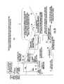
- FIG. 2 ais a simplified representation of a portion 201 of a computer algorithm according to an aspect of the invention for use in processing for determining the location of an object.
- Portion 201 of the algorithmis performed in processor 16 of FIGS. 1 a , 1 b , 1 c , 1 d , and 1 e .
- the logicstarts at a START block 210 , and proceeds to a block 212 .
- Block 212represents computations that may be performed in processor 16 of FIG. 1 a .
- Processor 16receives base terrain map information in the form of a two-dimension grid of altitude values as a function of latitude and longitude. Block 212 of FIG.
- Block 214represents the generation of azimuth/range cells covering the region of interest, with the azimuth extent of each azimuth/range cell being inversely related to the range. For example, one possible distribution might include
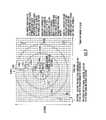
- FIG. 3is a simplified plan representation of the region 9 of interest, which is covered with many terrain or map points, some of which are illustrated and designated 7 .
- FIG. 3also illustrates some of the azimuth/range cells covering the region of interest, with the azimuth extent of each azimuth/range cell being inversely related to the range.
- the center 310 of the concentric circles 312 , 314 , and 316represents the location of the camera 12 of FIGS.
- the smallest circle, namely circle 312represents a range of 250 meters from the camera, pursuant to the example, while circles 314 and 316 represent ranges of 2000 and 6000 meters, respectively.
- azimuthis subdivided into 45° sectors, three of which are labeled 0 deg, 45 deg, and 90 deg.
- azimuthis divided in 5° increments, and some of the sectors are designated 5° and 10°.
- each range cellincludes a large number of terrain or map points 7 .
- the setup associated with FIG. 3is run once, and need not be re-run until such time as the location of the camera is changed, as the range, azimuth, and elevation are relative to a specific location.
- a block 216which represents the computation of range, azimuth, and elevation from camera point 310 ( FIG. 3 ) to the latitude, longitude, and altitude of each map point in the terrain grid.
- This computationmay be made in processor 16 of FIG. 1 a .
- the latitude, longitude and altitude in the terrain gridare then stored or placed in the appropriate one of the range/azimuth cells.
- the altitude information of the terrain grid pointdoes not affect the range/azimuth cell in which the information is stored, but the altitude information is available for each point in each range/azimuth cell. There may be many map points in each azimuth/range cell.
- map pointsare indicated by dots in FIG. 3 .
- the azimuth/range cellsare organized in terms of range and azimuth, and are used to store map points with values computed from block 212 of FIG. 2 a .
- These map pointsoriginated from a two dimensional latitude/longitude grid. The organization of the cells and storing the points in the cells provides an efficient means for looking up points, which is important since there may be millions of points to go through for a 10 km square area.
- range, azimuth, and elevationare computed from the camera point location to each latitude, longitude, and altitude in the grid to get the values and they are then stored in the appropriate cells.
- These sets of valuesare stored in computed terrain map of FIG. 1 a .
- the pointsmay be stored sorted by range.
- FIG. 4The plan view of FIG. 4 illustrates the geometry associated with determination of the cross range.
- the location of the camerais designated 412 .
- the cell in which the target is locatedis a curvilinear region designated 408 .
- Dash line 406represents a line extending from camera location 412 which passes through the angular center of the cell 418 , as suggested by equal angles ⁇ between line 406 and the cell edges.
- the location of the target within the cellis designated T.
- a line 404 extending from camera location 412 to the target location Tmakes an angle ⁇ with the cell centerline 406 .
- az pointis the azimuth angle of the map point at which the target is located, measured in degrees
- az center of cellis the azimuth of the center point of the cell 408 , measured in degrees.
- Block 220 of FIG. 2 arepresents determination of the elevation angle for each point lying within each cell, and the selection, from among all such elevation angles in the cell, of the maximum value (the highest point). Storing a maximum elevation for the cell of points helps with determining if one cell is obstructing the view of another cell “behind it” if the elevation angle to view it is lower. It should be noted that the logic steps 201 of FIG. 2 a need only be performed when the camera location changes.
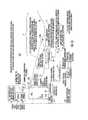
- the logic 201flows from FIG. 2 a by way of path 21 to block 230 of FIG. 2 b .
- the processing steps 202 of FIG. 2 bare performed in processor block 28 of FIGS. 1 a , 1 b , 1 c , 1 d , and 1 e .
- Block 230 of FIG. 2 brepresents the reading, in processor 28 of FIGS. 1 a , 1 b , 1 c , 1 d , and 1 e of the 2-D azimuth of the target derived in processor block 26 from the information contained in the object X,Y Cartesian data from the Video Analytics block 24 .
- Block 2 brepresents the selection or identification of the set of all cells (in all range sets) that span the 2-D azimuth of the target.
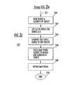
- Block 234represents the reading of the 2-D elevation of the target using camera point location information and orientation information to produce the azimuth and elevation angle of the target.
- Block 236represents the determination or identification of all the cells of the set in which the maximum elevation angle is greater than the elevation angle of the target output from Processor 26 .
- Decision block 238determines if there are a finite number of cells (one or more cells) having maximum elevation angle greater than the target elevation angle. If no cells of the set have maximum elevation angle greater than the target elevation angle, the target is deemed to be above the horizon, so the logic of FIG.
- Block 244represents the selection of that cell, from among those having maximum elevations greater than the sensed 2-D elevation, which is closest to the sensor (the camera in this example). The logic of block 236 iterates through the cells until the first one is found which has a maximum elevation angle greater than the target elevation angle.
- Block 246represents the selection, from within the closest cell selected in block 244 , of the map point which is closest in azimuth and elevation to the sensed azimuth and elevation of the target. This map point is deemed to be the location of the target.
- Block 248represents the reporting of the selected map point as being the location of the target.
- Logic 202 of FIG. 2 bends at an END block 250 .
- FIG. 5is a cross sectional or elevation view of the terrain of FIG. 1 a that helps to illustrate why the selection of the closest cell with the highest elevation in the logic flow operates to identify the location of the target object.
- Cell R 0has a maximum elevation angle of ⁇ 80 degrees
- cell R 1has a maximum elevation angle of ⁇ 60 degrees
- cell R 2has a maximum elevation angle of ⁇ 40 degrees
- cell R 3has a maximum elevation angle of ⁇ 15 degrees
- cell R 4has a maximum elevation angle of ⁇ 5 degrees
- cell R 5has a maximum elevation angle of ⁇ 7 degrees
- cell R 6has a maximum elevation angle of ⁇ 20 degrees
- cell R 7has a maximum elevation angle of ⁇ 3 degrees
- cell R 8has a maximum elevation angle of +1 degree
- cell R 9has a maximum elevation angle of +5 degrees
- cell R 10has a maximum elevation angle of +8 degrees.
- the target object 40lies below the maximum elevation in range cell R 4 .
- the camera 12detects the object as being at a depression angle of ⁇ 8°. Therefore, cells R 4 , R 5 , R 7 , R 8 , R 9 , and R 10 have maximum cell elevation angles that are greater or higher.
- Block 244 of the logic of FIGS. 2 a and 2 bselects the cell which is closest to the camera, in this case cell R 4 , as the one in which the target is located, as this is the one that the vector from the camera at the elevation angle of ⁇ 8 degrees first intersects.
- Cells behind (more remote from camera 12 than) cell R 4are either obstructed or merely have maximum elevation angles above the elevation angle at which the target is located.
- cells R 5 and R 7are obstructed from the camera's view, and cells R 8 , R 9 , and R 10 have elevation angles greater than that at which the target lies.
- Cell R 7has elevation angles which are the same as those of the target, but it is more remote from the camera than cell R 5 , so is not selected.
- the utilization device(s)may include a controller 60 for a controllable field-of-view camera 62 , which is preferably a pan, tilt, zoom, (PTZ) and speed controllable camera, which can be directed toward the location of the target to provide a zoomed view.
- the utilization device(s) of FIG. 1 amay include map display device 63 , and/or an anti-incursion weapon or close surveillance device represented as a block 65 .
- the PTZ interrogation camera 61 and anti-incursion or close surveillance device 65operate in mutually similar manners, in that a processor or operator selects an object of interest, and upon selection the 3D coordinates would be communicated to the system.
- a PTZ interrogation camera and a system connected to ituses the stream of object positions to focus and optionally follow the target, thereby allowing the operator to more effectively identity the object, such as what the person may be wearing or carrying or counting the number of individuals in a group of people traveling closely together. This type of use supports operations in determining the correct response to send for the incursion as number of responders and equipment.
- the camera control block 60in the case of the system of FIG. 1 b controls the camera 12 rather than a separate camera. This admits of the possibility that, during a zooming function of camera 12 that reduces the field of view to less than the entire region of interest, intrusion might occur in the region not being monitored. This could be a temporary action to closely monitor the target before resuming wide area surveillance.
- FIG. 1 fis similar to FIG. 1 d , but illustrates separate processors 601 and 602 .
- Processor 602receives base terrain map information from block 18 and generates a further computed terrain map 603 for the vicinity of the radar 8 . This is the same process used in Processor 16 . If the radar 8 and the camera 12 happen to be collocated, the same computed terrain map can be used for both.
- processor 601uses the measured range and azimuth from the radar together with the computed terrain map to determine the target's 3-D location.
- FIG. 2 cillustrates the processing 203 in Processor 601 to generate a 3-D target location from a 2-D radar track.
- the logic of FIG. 2 ccontinues from the logic 201 of FIG. 2 a .
- Block 260 of logic 203represents the reading of the target range and azimuth information provided by the radar.
- Block 262represents the determination of the set of range/azimuth cells in which the radar range is found.
- the cross-range of the targetis determined in block 264 as described in conjunction with FIG. 4 .
- Block 266represents the selection of that map point which is closest to the range and azimuth of the target.
- the map pointis reported (block 268 ) and the logic ends ( 270 ).
- the radar datacan be fused with the camera data to more accurately locate the target, as the radar provides better range resolution than the camera with its processing.
- FIG. 1 gis similar to FIG. 1 b , but includes a radar 8 , radar processors 601 and 602 , computed terrain map 603 , and a further processor 604 which correlates and fuses the target location information from the radar and the camera.
- the fused informationcan be used for display, or to actuate or command an anti-incursion weapon or close surveillance device.
- any number of range incrementscan be used, and any number of azimuth sectors in each range increment, meaning that the azimuth sector angle increments can be greater or less than the 2°, 5°, and 45° described in the example.
- a methodis for determining the location of a moving object ( 40 ) in a region of interest ( 9 ).
- the methodcomprises the steps of observing the region of interest ( 9 ) with a camera ( 12 ) to produce a frame-sequential video signal representing at least a part of the region of interest ( 9 ).
- Geospatial coordinates of the location of the camera ( 12 ), and information relating to the azimuth angle, elevation angle, and field of view of the camera ( 12 )are provided ( 14 ).
- the video signalis applied to video analytics ( 24 ) processing for detecting an object(s) ( 40 ) which move(s) from frame to frame of the video signal, and for identifying the location in a two-dimensional Cartesian coordinate system of an object ( 40 ) which moves from frame to frame of the video signal.
- the location in a two-dimensional Cartesian coordinate system of an object ( 40 ) which moves from frame to frame of the video signalis converted to a location in expressed in terms of azimuth and elevation angle.
- a computed map ( 22 )is provided that includes the altitudes of geospatial coordinate points, at least in the region of interest ( 9 ), together with computed range, azimuth, and elevation from the camera ( 12 ) location to each computed map ( 22 ) point.
- the computed map ( 22 ) informationis processed ( 28 ) together with the location of the object ( 40 ) expressed in terms of azimuth and elevation angle and together with the location of the camera ( 12 ) and information relating to the azimuth angle, elevation angle, and field of view of the camera ( 12 ), for producing information (path 30 ) relating to the location of the moving object ( 40 ) in three dimensions.
- the informationmay be in the form of longitude, latitude, and altitude.
- the three-dimensional location of the moving objectcan be displayed, or a zoom camera may be directed toward the location for better identification, or a weapon or surveillance device may be directed toward the location.
- the step of providing a computed map ( 22 ) including the altitudes of geospatial coordinate points, at least in the region of interest ( 9 ), together with computed range, azimuth, and elevation from the camera ( 12 ) location to each computed map ( 22 ) pointcomprises the step of providing a terrain map ( 18 ) including the altitudes of geospatial coordinate points, at least in the regions of interest.
- These geospatial coordinate pointsmay be expressed in terms of longitude and latitude.
- the terrain map ( 18 ) informationis processed ( 16 ) together with the location of the camera ( 12 ) and information relating to the azimuth angle, elevation angle, and field of view of the camera ( 12 ), to produce a computed map ( 18 ) including latitude, longitude and altitude as a function of azimuth and elevation.
- the step of processing the terrain map ( 18 ) together with the location of the object ( 40 ) in azimuth and elevation angle together with the location of the camera ( 12 ) and information relating to the azimuth angle, elevation angle, and field of view of the camera ( 12 ), for producing information relating to the location in three dimensions of the moving object ( 40 ),includes the step ( FIG. 3 ) of identifying a plurality of contiguous or juxtaposed azimuth-range cells covering the terrain point ( 7 )s available from the terrain map ( 18 ), so that plural terrain point ( 7 )s lie in each range cell. The range, azimuth and elevation relative to the camera ( 12 ) location are calculated for each terrain point ( 7 ).
- the azimuth-range cell in which the target is locatedis determined. That terrain point ( 7 ) within that one of the azimuth-range cells which is closest to the target is identified. That terrain point ( 7 ) within that one of the azimuth-range cells which is closest to the target is deemed to be the location of the target.
Landscapes
- Engineering & Computer Science (AREA)
- Radar, Positioning & Navigation (AREA)
- Remote Sensing (AREA)
- Physics & Mathematics (AREA)
- General Physics & Mathematics (AREA)
- Computer Networks & Wireless Communication (AREA)
- Automation & Control Theory (AREA)
- Electromagnetism (AREA)
- Radar Systems Or Details Thereof (AREA)
Abstract
Description
| Cell 1: | 00 to 45 degrees | 0-250 | meters |
| Cell 2: | 45 to 90 degrees | 0-250 | meters |
| Cell 3: | 00 to 05 degrees | 250-2000 | meters |
| Cell 4: | 05 to 10 degrees | 250-2000 | meters |
| Cell 5: | 00 to 02 degrees | 2000-6000 | meters |
| Cell 6: | 02 to 04 degrees | 2000-6000 | meters |
Cross_range=range*(azpoint−azcenter of cell)*pi/180° (1)
where:
Claims (20)
Priority Applications (1)
| Application Number | Priority Date | Filing Date | Title |
|---|---|---|---|
| US11/807,309US8049658B1 (en) | 2007-05-25 | 2007-05-25 | Determination of the three-dimensional location of a target viewed by a camera |
Applications Claiming Priority (1)
| Application Number | Priority Date | Filing Date | Title |
|---|---|---|---|
| US11/807,309US8049658B1 (en) | 2007-05-25 | 2007-05-25 | Determination of the three-dimensional location of a target viewed by a camera |
Publications (1)
| Publication Number | Publication Date |
|---|---|
| US8049658B1true US8049658B1 (en) | 2011-11-01 |
Family
ID=44839614
Family Applications (1)
| Application Number | Title | Priority Date | Filing Date |
|---|---|---|---|
| US11/807,309Expired - Fee RelatedUS8049658B1 (en) | 2007-05-25 | 2007-05-25 | Determination of the three-dimensional location of a target viewed by a camera |
Country Status (1)
| Country | Link |
|---|---|
| US (1) | US8049658B1 (en) |
Cited By (44)
| Publication number | Priority date | Publication date | Assignee | Title |
|---|---|---|---|---|
| US20090041338A1 (en)* | 2007-08-09 | 2009-02-12 | Fujifilm Corporation | Photographing field angle calculation apparatus |
| US20090244280A1 (en)* | 2008-03-25 | 2009-10-01 | Thomas Hanses | Detection device and method for detecting fires along a monitoring path |
| US20110080467A1 (en)* | 2008-03-14 | 2011-04-07 | Damien Daly | a method of generating a profile of the path taken by an object travelling over a 3-dimensional surface |
| US20120188388A1 (en)* | 2011-01-20 | 2012-07-26 | Samsung Techwin Co., Ltd. | Method of controlling camera |
| CN103258322A (en)* | 2012-11-01 | 2013-08-21 | 南京朋源电气有限公司 | Determining method of moving target height under different projection angles |
| US8768315B2 (en) | 2012-09-05 | 2014-07-01 | Motorola Solutions, Inc. | Method and apparatus for identifying a suspect through multiple correlated device identities |
| US20140236480A1 (en)* | 2013-02-20 | 2014-08-21 | Electronics And Telecommunications Research Institute | Real-time movement path estimation apparatus and method using visible light communication |
| US20140314275A1 (en)* | 2013-04-19 | 2014-10-23 | Polaris Sensor Technologies, Inc. | Pedestrian Right of Way Monitoring and Reporting System and Method |
| US8892132B2 (en) | 2012-09-05 | 2014-11-18 | Motorola Solutions, Inc. | Analytic and tracking systems and methods using over-the-air identifiers of mobile devices |
| US20150222860A1 (en)* | 2012-09-24 | 2015-08-06 | Robert Bosch Gmbh | Client device for displaying images of a controllable camera, method, computer program and monitoring system comprising said client device |
| WO2015160290A1 (en)* | 2014-04-14 | 2015-10-22 | Saab Vricon Systems Ab | A target determining method and system |
| WO2015160292A1 (en)* | 2014-04-14 | 2015-10-22 | Saab Vricon Systems Ab | A target determining method and system |
| US20150341532A1 (en)* | 2007-11-28 | 2015-11-26 | Flir Systems, Inc. | Infrared camera systems and methods |
| US20160050360A1 (en)* | 2013-04-05 | 2016-02-18 | Cinema Control Laboratories Inc. | System and Method for Controlling an Equipment Related to Image Capture |
| US20160125655A1 (en)* | 2013-06-07 | 2016-05-05 | Nokia Technologies Oy | A method and apparatus for self-adaptively visualizing location based digital information |
| US9639760B2 (en) | 2012-09-07 | 2017-05-02 | Siemens Schweiz Ag | Methods and apparatus for establishing exit/entry criteria for a secure location |
| US9671493B1 (en)* | 2014-09-19 | 2017-06-06 | Hrl Laboratories, Llc | Automated scheduling of radar-cued camera system for optimizing visual inspection (detection) of radar targets |
| US20180082128A1 (en)* | 2016-09-20 | 2018-03-22 | Hewlett Packard Enterprise Development Lp | Detecting Changes in 3D Scenes |
| US10217294B2 (en) | 2008-05-07 | 2019-02-26 | Microsoft Technology Licensing, Llc | Procedural authoring |
| US10254395B2 (en)* | 2013-12-04 | 2019-04-09 | Trimble Inc. | System and methods for scanning with integrated radar detection and image capture |
| US10349032B2 (en)* | 2016-09-30 | 2019-07-09 | Veoneer Us, Inc. | Vehicle occupant head positioning system |
| US10359779B2 (en) | 2016-03-22 | 2019-07-23 | Aurora Flight Sciences Corporation | Aircrew automation system and method |
| US20190287257A1 (en)* | 2016-05-17 | 2019-09-19 | Obschestvo S Ogranichennoi Otvetstvennostyu "Disicon" | Method and system for measuring the distance to remote objects |
| US10453351B2 (en) | 2017-07-17 | 2019-10-22 | Aurora Flight Sciences Corporation | System and method for detecting obstacles in aerial systems |
| US10509415B2 (en) | 2017-07-27 | 2019-12-17 | Aurora Flight Sciences Corporation | Aircrew automation system and method with integrated imaging and force sensing modalities |
| US20190391254A1 (en)* | 2018-06-20 | 2019-12-26 | Rapsodo Pte. Ltd. | Radar and camera-based data fusion |
| US10683067B2 (en) | 2018-08-10 | 2020-06-16 | Buffalo Automation Group Inc. | Sensor system for maritime vessels |
| US10754017B2 (en)* | 2017-06-09 | 2020-08-25 | Toyota Jidosha Kabushiki Kaisha | Target object information acquisition apparatus |
| US10782691B2 (en) | 2018-08-10 | 2020-09-22 | Buffalo Automation Group Inc. | Deep learning and intelligent sensing system integration |
| US10816970B2 (en) | 2017-06-15 | 2020-10-27 | Aurora Flight Sciences Corporation | System and method for performing an emergency descent and landing |
| US10850397B2 (en) | 2018-04-19 | 2020-12-01 | Aurora Flight Sciences Corporation | System and method for providing in-cockpit actuation of aircraft controls |
| US10875662B2 (en) | 2018-04-19 | 2020-12-29 | Aurora Flight Sciences Corporation | Method of robot manipulation in a vibration environment |
| US10928508B2 (en) | 2019-04-12 | 2021-02-23 | Ford Global Technologies, Llc | Camera and radar fusion |
| US10936907B2 (en) | 2018-08-10 | 2021-03-02 | Buffalo Automation Group Inc. | Training a deep learning system for maritime applications |
| US11037453B2 (en) | 2018-10-12 | 2021-06-15 | Aurora Flight Sciences Corporation | Adaptive sense and avoid system |
| CN112995578A (en)* | 2019-12-02 | 2021-06-18 | 杭州海康威视数字技术股份有限公司 | Electronic map display method, device and system and electronic equipment |
| US11151810B2 (en) | 2018-10-12 | 2021-10-19 | Aurora Flight Sciences Corporation | Adaptable vehicle monitoring system |
| US20210383144A1 (en)* | 2020-06-08 | 2021-12-09 | Microsoft Technology Licensing, Llc | Geolocation with aerial and satellite photography |
| US11199631B2 (en) | 2017-04-07 | 2021-12-14 | Criterionix, L.L.C. | Apparatus and methods for geo-locating one or more objects |
| US11255959B2 (en) | 2017-06-02 | 2022-02-22 | Sony Corporation | Apparatus, method and computer program for computer vision |
| CN114754743A (en)* | 2022-04-18 | 2022-07-15 | 中国人民解放军陆军军事交通学院军事交通运输研究所 | Target positioning method for carrying multiple PTZ cameras on intelligent ground unmanned platform |
| US11399137B2 (en) | 2018-08-10 | 2022-07-26 | Aurora Flight Sciences Corporation | Object-tracking system |
| US11630198B2 (en) | 2017-03-31 | 2023-04-18 | FLIR Belgium BVBA | Visually correlated radar systems and methods |
| US20230314594A1 (en)* | 2020-08-25 | 2023-10-05 | Groundprobe Pty Ltd | Slope failure monitoring system |
Citations (28)
| Publication number | Priority date | Publication date | Assignee | Title |
|---|---|---|---|---|
| US5341142A (en)* | 1987-07-24 | 1994-08-23 | Northrop Grumman Corporation | Target acquisition and tracking system |
| US5742699A (en)* | 1995-08-31 | 1998-04-21 | Adkins; William A. | Passive velocity measuring device |
| US6233522B1 (en)* | 1998-07-06 | 2001-05-15 | Alliedsignal Inc. | Aircraft position validation using radar and digital terrain elevation database |
| US6236351B1 (en)* | 1998-07-06 | 2001-05-22 | Alliedsignal Inc. | Method and apparatus for implementing automatic tilt control of a radar antenna on an aircraft |
| US20020049530A1 (en)* | 1998-04-15 | 2002-04-25 | George Poropat | Method of tracking and sensing position of objects |
| US6414712B1 (en)* | 1995-12-13 | 2002-07-02 | Daimlerchrylsler, Ag | Vehicle navigational system and signal processing method for said navigational system |
| US6563452B1 (en)* | 1998-07-06 | 2003-05-13 | Honeywell International Inc. | Apparatus and method for determining wind profiles and for predicting clear air turbulence |
| US20040046690A1 (en)* | 2000-12-04 | 2004-03-11 | Brian Reeves | Slope monitoring system |
| US20040083035A1 (en)* | 1996-09-25 | 2004-04-29 | Ellis Christ G. | Apparatus and method for automatic vision enhancement in a traffic complex |
| US20040095999A1 (en)* | 2001-01-24 | 2004-05-20 | Erick Piehl | Method for compressing video information |
| US6744397B1 (en)* | 2003-06-11 | 2004-06-01 | Honeywell International, Inc. | Systems and methods for target location |
| US20040105579A1 (en)* | 2001-03-28 | 2004-06-03 | Hirofumi Ishii | Drive supporting device |
| US20040105573A1 (en)* | 2002-10-15 | 2004-06-03 | Ulrich Neumann | Augmented virtual environments |
| US6771207B1 (en)* | 2003-02-11 | 2004-08-03 | Unisys Corporation | Establishing radar coverage, blockage, and clutter region maps for radar product data based on terrain elevation data |
| US20040247174A1 (en)* | 2000-01-20 | 2004-12-09 | Canon Kabushiki Kaisha | Image processing apparatus |
| US20050119828A1 (en)* | 2000-10-16 | 2005-06-02 | Lahn Richard H. | Remote image management system (rims) |
| US20050149251A1 (en)* | 2000-07-18 | 2005-07-07 | University Of Minnesota | Real time high accuracy geospatial database for onboard intelligent vehicle applications |
| US6965342B2 (en)* | 2001-04-26 | 2005-11-15 | Eads Deutschland Gmbh | Method for recognizing and identifying objects |
| US7049998B1 (en)* | 2004-09-10 | 2006-05-23 | United States Of America As Represented By The Secretary Of The Navy | Integrated radar, optical surveillance, and sighting system |
| US20060238536A1 (en)* | 1999-07-30 | 2006-10-26 | Canon Kabushiki Kaisha | Image synthesis method, image synthesis apparatus, and storage medium |
| US7176830B2 (en)* | 2004-11-26 | 2007-02-13 | Omron Corporation | Image processing system for mounting to a vehicle |
| US20070075892A1 (en)* | 2005-10-03 | 2007-04-05 | Omron Corporation | Forward direction monitoring device |
| US7257478B2 (en)* | 2004-01-21 | 2007-08-14 | Nissan Motor Co., Ltd. | Vehicle driving control device |
| US7486291B2 (en)* | 2003-07-08 | 2009-02-03 | Berson Barry L | Systems and methods using enhanced vision to provide out-the-window displays for a device |
| US7619626B2 (en)* | 2003-03-01 | 2009-11-17 | The Boeing Company | Mapping images from one or more sources into an image for display |
| US20110001657A1 (en)* | 2006-06-08 | 2011-01-06 | Fox Philip A | Sensor suite and signal processing for border surveillance |
| US7880668B1 (en)* | 2008-12-08 | 2011-02-01 | Lockheed Martin Corproation | Automated radar elevation angle configuration |
| US7982767B2 (en)* | 2003-11-11 | 2011-07-19 | Supersonic Aerospace International, Llc | System and method for mounting sensors and cleaning sensor apertures for out-the-window displays |
- 2007
- 2007-05-25USUS11/807,309patent/US8049658B1/ennot_activeExpired - Fee Related
Patent Citations (30)
| Publication number | Priority date | Publication date | Assignee | Title |
|---|---|---|---|---|
| US5341142A (en)* | 1987-07-24 | 1994-08-23 | Northrop Grumman Corporation | Target acquisition and tracking system |
| US5742699A (en)* | 1995-08-31 | 1998-04-21 | Adkins; William A. | Passive velocity measuring device |
| US6414712B1 (en)* | 1995-12-13 | 2002-07-02 | Daimlerchrylsler, Ag | Vehicle navigational system and signal processing method for said navigational system |
| US20040083035A1 (en)* | 1996-09-25 | 2004-04-29 | Ellis Christ G. | Apparatus and method for automatic vision enhancement in a traffic complex |
| US20020049530A1 (en)* | 1998-04-15 | 2002-04-25 | George Poropat | Method of tracking and sensing position of objects |
| US6442476B1 (en)* | 1998-04-15 | 2002-08-27 | Research Organisation | Method of tracking and sensing position of objects |
| US6233522B1 (en)* | 1998-07-06 | 2001-05-15 | Alliedsignal Inc. | Aircraft position validation using radar and digital terrain elevation database |
| US6236351B1 (en)* | 1998-07-06 | 2001-05-22 | Alliedsignal Inc. | Method and apparatus for implementing automatic tilt control of a radar antenna on an aircraft |
| US6563452B1 (en)* | 1998-07-06 | 2003-05-13 | Honeywell International Inc. | Apparatus and method for determining wind profiles and for predicting clear air turbulence |
| US20060238536A1 (en)* | 1999-07-30 | 2006-10-26 | Canon Kabushiki Kaisha | Image synthesis method, image synthesis apparatus, and storage medium |
| US20040247174A1 (en)* | 2000-01-20 | 2004-12-09 | Canon Kabushiki Kaisha | Image processing apparatus |
| US20050149251A1 (en)* | 2000-07-18 | 2005-07-07 | University Of Minnesota | Real time high accuracy geospatial database for onboard intelligent vehicle applications |
| US20050119828A1 (en)* | 2000-10-16 | 2005-06-02 | Lahn Richard H. | Remote image management system (rims) |
| US6850183B2 (en)* | 2000-12-04 | 2005-02-01 | Groundprobe Pty Limited | Slope monitoring system |
| US20040046690A1 (en)* | 2000-12-04 | 2004-03-11 | Brian Reeves | Slope monitoring system |
| US20040095999A1 (en)* | 2001-01-24 | 2004-05-20 | Erick Piehl | Method for compressing video information |
| US20040105579A1 (en)* | 2001-03-28 | 2004-06-03 | Hirofumi Ishii | Drive supporting device |
| US6965342B2 (en)* | 2001-04-26 | 2005-11-15 | Eads Deutschland Gmbh | Method for recognizing and identifying objects |
| US20040105573A1 (en)* | 2002-10-15 | 2004-06-03 | Ulrich Neumann | Augmented virtual environments |
| US6771207B1 (en)* | 2003-02-11 | 2004-08-03 | Unisys Corporation | Establishing radar coverage, blockage, and clutter region maps for radar product data based on terrain elevation data |
| US7619626B2 (en)* | 2003-03-01 | 2009-11-17 | The Boeing Company | Mapping images from one or more sources into an image for display |
| US6744397B1 (en)* | 2003-06-11 | 2004-06-01 | Honeywell International, Inc. | Systems and methods for target location |
| US7486291B2 (en)* | 2003-07-08 | 2009-02-03 | Berson Barry L | Systems and methods using enhanced vision to provide out-the-window displays for a device |
| US7982767B2 (en)* | 2003-11-11 | 2011-07-19 | Supersonic Aerospace International, Llc | System and method for mounting sensors and cleaning sensor apertures for out-the-window displays |
| US7257478B2 (en)* | 2004-01-21 | 2007-08-14 | Nissan Motor Co., Ltd. | Vehicle driving control device |
| US7049998B1 (en)* | 2004-09-10 | 2006-05-23 | United States Of America As Represented By The Secretary Of The Navy | Integrated radar, optical surveillance, and sighting system |
| US7176830B2 (en)* | 2004-11-26 | 2007-02-13 | Omron Corporation | Image processing system for mounting to a vehicle |
| US20070075892A1 (en)* | 2005-10-03 | 2007-04-05 | Omron Corporation | Forward direction monitoring device |
| US20110001657A1 (en)* | 2006-06-08 | 2011-01-06 | Fox Philip A | Sensor suite and signal processing for border surveillance |
| US7880668B1 (en)* | 2008-12-08 | 2011-02-01 | Lockheed Martin Corproation | Automated radar elevation angle configuration |
Cited By (67)
| Publication number | Priority date | Publication date | Assignee | Title |
|---|---|---|---|---|
| US8326023B2 (en)* | 2007-08-09 | 2012-12-04 | Fujifilm Corporation | Photographing field angle calculation apparatus |
| US20090041338A1 (en)* | 2007-08-09 | 2009-02-12 | Fujifilm Corporation | Photographing field angle calculation apparatus |
| US9615006B2 (en)* | 2007-11-28 | 2017-04-04 | Flir Systems, Inc. | Infrared camera systems and methods for facilitating target position acquisition |
| US20150341532A1 (en)* | 2007-11-28 | 2015-11-26 | Flir Systems, Inc. | Infrared camera systems and methods |
| US20110080467A1 (en)* | 2008-03-14 | 2011-04-07 | Damien Daly | a method of generating a profile of the path taken by an object travelling over a 3-dimensional surface |
| US20090244280A1 (en)* | 2008-03-25 | 2009-10-01 | Thomas Hanses | Detection device and method for detecting fires along a monitoring path |
| US10217294B2 (en) | 2008-05-07 | 2019-02-26 | Microsoft Technology Licensing, Llc | Procedural authoring |
| US20120188388A1 (en)* | 2011-01-20 | 2012-07-26 | Samsung Techwin Co., Ltd. | Method of controlling camera |
| US8854461B2 (en)* | 2011-01-20 | 2014-10-07 | Samsung Techwin Co., Ltd. | Method of controlling camera |
| US8892132B2 (en) | 2012-09-05 | 2014-11-18 | Motorola Solutions, Inc. | Analytic and tracking systems and methods using over-the-air identifiers of mobile devices |
| US9084103B2 (en) | 2012-09-05 | 2015-07-14 | Motorola Solutions, Inc. | Analytic and tracking systems and methods using over-the-air identifiers of mobile devices |
| US8768315B2 (en) | 2012-09-05 | 2014-07-01 | Motorola Solutions, Inc. | Method and apparatus for identifying a suspect through multiple correlated device identities |
| US9639760B2 (en) | 2012-09-07 | 2017-05-02 | Siemens Schweiz Ag | Methods and apparatus for establishing exit/entry criteria for a secure location |
| US20150222860A1 (en)* | 2012-09-24 | 2015-08-06 | Robert Bosch Gmbh | Client device for displaying images of a controllable camera, method, computer program and monitoring system comprising said client device |
| US10257467B2 (en)* | 2012-09-24 | 2019-04-09 | Robert Bosch Gmbh | Client device for displaying images of a controllable camera, method, computer program and monitoring system comprising said client device |
| CN103258322A (en)* | 2012-11-01 | 2013-08-21 | 南京朋源电气有限公司 | Determining method of moving target height under different projection angles |
| US20140236480A1 (en)* | 2013-02-20 | 2014-08-21 | Electronics And Telecommunications Research Institute | Real-time movement path estimation apparatus and method using visible light communication |
| US10306134B2 (en) | 2013-04-05 | 2019-05-28 | Andra Motion Technologies Inc. | System and method for controlling an equipment related to image capture |
| US9912857B2 (en)* | 2013-04-05 | 2018-03-06 | Andra Motion Technologies Inc. | System and method for controlling an equipment related to image capture |
| US20160050360A1 (en)* | 2013-04-05 | 2016-02-18 | Cinema Control Laboratories Inc. | System and Method for Controlling an Equipment Related to Image Capture |
| US20140314275A1 (en)* | 2013-04-19 | 2014-10-23 | Polaris Sensor Technologies, Inc. | Pedestrian Right of Way Monitoring and Reporting System and Method |
| US20160364614A1 (en)* | 2013-04-19 | 2016-12-15 | Polaris Sensor Technologies, Inc. | Pedestrian Right of Way Monitoring and Reporting System and Method |
| US9436877B2 (en)* | 2013-04-19 | 2016-09-06 | Polaris Sensor Technologies, Inc. | Pedestrian right of way monitoring and reporting system and method |
| US9824277B2 (en)* | 2013-04-19 | 2017-11-21 | Polaris Sensor Technologies, Inc. | Pedestrian right of way monitoring and reporting system and method |
| US10713490B2 (en)* | 2013-04-19 | 2020-07-14 | Polaris Sensor Technologies, Inc. | Traffic monitoring and reporting system and method |
| US20180075303A1 (en)* | 2013-04-19 | 2018-03-15 | Polaris Sensor Technologies, Inc. | Traffic Monitoring and Reporting System and Method |
| US20160125655A1 (en)* | 2013-06-07 | 2016-05-05 | Nokia Technologies Oy | A method and apparatus for self-adaptively visualizing location based digital information |
| US10254395B2 (en)* | 2013-12-04 | 2019-04-09 | Trimble Inc. | System and methods for scanning with integrated radar detection and image capture |
| WO2015160292A1 (en)* | 2014-04-14 | 2015-10-22 | Saab Vricon Systems Ab | A target determining method and system |
| WO2015160290A1 (en)* | 2014-04-14 | 2015-10-22 | Saab Vricon Systems Ab | A target determining method and system |
| US9689673B2 (en) | 2014-04-14 | 2017-06-27 | Saab Vricon Systems Ab | Target determining method and system |
| US10290140B2 (en) | 2014-04-14 | 2019-05-14 | Vricon Systems Aktiebolag | Target determining method and system |
| US9671493B1 (en)* | 2014-09-19 | 2017-06-06 | Hrl Laboratories, Llc | Automated scheduling of radar-cued camera system for optimizing visual inspection (detection) of radar targets |
| US10642270B2 (en) | 2016-03-22 | 2020-05-05 | Aurora Flight Sciences Corporation | Aircrew automation system and method |
| US10359779B2 (en) | 2016-03-22 | 2019-07-23 | Aurora Flight Sciences Corporation | Aircrew automation system and method |
| US20190287257A1 (en)* | 2016-05-17 | 2019-09-19 | Obschestvo S Ogranichennoi Otvetstvennostyu "Disicon" | Method and system for measuring the distance to remote objects |
| US20180082128A1 (en)* | 2016-09-20 | 2018-03-22 | Hewlett Packard Enterprise Development Lp | Detecting Changes in 3D Scenes |
| US10235572B2 (en)* | 2016-09-20 | 2019-03-19 | Entit Software Llc | Detecting changes in 3D scenes |
| US10349032B2 (en)* | 2016-09-30 | 2019-07-09 | Veoneer Us, Inc. | Vehicle occupant head positioning system |
| US11630198B2 (en) | 2017-03-31 | 2023-04-18 | FLIR Belgium BVBA | Visually correlated radar systems and methods |
| US11199631B2 (en) | 2017-04-07 | 2021-12-14 | Criterionix, L.L.C. | Apparatus and methods for geo-locating one or more objects |
| US11255959B2 (en) | 2017-06-02 | 2022-02-22 | Sony Corporation | Apparatus, method and computer program for computer vision |
| US10754017B2 (en)* | 2017-06-09 | 2020-08-25 | Toyota Jidosha Kabushiki Kaisha | Target object information acquisition apparatus |
| US10816970B2 (en) | 2017-06-15 | 2020-10-27 | Aurora Flight Sciences Corporation | System and method for performing an emergency descent and landing |
| US10453351B2 (en) | 2017-07-17 | 2019-10-22 | Aurora Flight Sciences Corporation | System and method for detecting obstacles in aerial systems |
| US11181935B2 (en) | 2017-07-17 | 2021-11-23 | Aurora Flight Sciences Corporation | System and method for detecting obstacles in aerial systems |
| US10509415B2 (en) | 2017-07-27 | 2019-12-17 | Aurora Flight Sciences Corporation | Aircrew automation system and method with integrated imaging and force sensing modalities |
| US11378988B2 (en) | 2017-07-27 | 2022-07-05 | Aurora Flight Sciences Corporation | Aircrew automation system and method with integrated imaging and force sensing modalities |
| US10850397B2 (en) | 2018-04-19 | 2020-12-01 | Aurora Flight Sciences Corporation | System and method for providing in-cockpit actuation of aircraft controls |
| US10875662B2 (en) | 2018-04-19 | 2020-12-29 | Aurora Flight Sciences Corporation | Method of robot manipulation in a vibration environment |
| US10754025B2 (en)* | 2018-06-20 | 2020-08-25 | Rapsodo Pte. Ltd. | Radar and camera-based data fusion |
| US11747461B2 (en) | 2018-06-20 | 2023-09-05 | Rapsodo Pte. Ltd. | Radar and camera-based data fusion |
| US20190391254A1 (en)* | 2018-06-20 | 2019-12-26 | Rapsodo Pte. Ltd. | Radar and camera-based data fusion |
| US11399137B2 (en) | 2018-08-10 | 2022-07-26 | Aurora Flight Sciences Corporation | Object-tracking system |
| US10936907B2 (en) | 2018-08-10 | 2021-03-02 | Buffalo Automation Group Inc. | Training a deep learning system for maritime applications |
| US10683067B2 (en) | 2018-08-10 | 2020-06-16 | Buffalo Automation Group Inc. | Sensor system for maritime vessels |
| US10782691B2 (en) | 2018-08-10 | 2020-09-22 | Buffalo Automation Group Inc. | Deep learning and intelligent sensing system integration |
| US12002373B2 (en) | 2018-10-12 | 2024-06-04 | Aurora Flight Sciences Corporation, a subsidiary of The Boeing Company | Adaptive sense and avoid system |
| US11151810B2 (en) | 2018-10-12 | 2021-10-19 | Aurora Flight Sciences Corporation | Adaptable vehicle monitoring system |
| US11037453B2 (en) | 2018-10-12 | 2021-06-15 | Aurora Flight Sciences Corporation | Adaptive sense and avoid system |
| US10928508B2 (en) | 2019-04-12 | 2021-02-23 | Ford Global Technologies, Llc | Camera and radar fusion |
| CN112995578A (en)* | 2019-12-02 | 2021-06-18 | 杭州海康威视数字技术股份有限公司 | Electronic map display method, device and system and electronic equipment |
| CN112995578B (en)* | 2019-12-02 | 2022-09-02 | 杭州海康威视数字技术股份有限公司 | Electronic map display method, device and system and electronic equipment |
| US11656365B2 (en)* | 2020-06-08 | 2023-05-23 | Microsoft Technology Licensing, Llc | Geolocation with aerial and satellite photography |
| US20210383144A1 (en)* | 2020-06-08 | 2021-12-09 | Microsoft Technology Licensing, Llc | Geolocation with aerial and satellite photography |
| US20230314594A1 (en)* | 2020-08-25 | 2023-10-05 | Groundprobe Pty Ltd | Slope failure monitoring system |
| CN114754743A (en)* | 2022-04-18 | 2022-07-15 | 中国人民解放军陆军军事交通学院军事交通运输研究所 | Target positioning method for carrying multiple PTZ cameras on intelligent ground unmanned platform |
Similar Documents
| Publication | Publication Date | Title |
|---|---|---|
| US8049658B1 (en) | Determination of the three-dimensional location of a target viewed by a camera | |
| US9520040B2 (en) | System and method for real-time 3-D object tracking and alerting via networked sensors | |
| US7889232B2 (en) | Method and system for surveillance of vessels | |
| US9420177B2 (en) | Panoramic view imaging system with laser range finding and blind spot detection | |
| US9253453B2 (en) | Automatic video surveillance system and method | |
| US8180107B2 (en) | Active coordinated tracking for multi-camera systems | |
| US5128874A (en) | Inertial navigation sensor integrated obstacle detection system | |
| AU2021351611B2 (en) | Multi-source 3-dimensional detection and tracking | |
| CN108416361A (en) | A kind of information fusion system and method based on sea survaillance | |
| US20080314234A1 (en) | Distributed ground-based threat detection system | |
| CN110537109A (en) | Sensing component for autonomous driving | |
| KR102001594B1 (en) | Radar-camera fusion disaster tracking system and method for scanning invisible space | |
| CN104166137A (en) | Target comprehensive parameter tracking measurement method based on display of radar warning situation map | |
| JP2008538474A (en) | Automated monitoring system | |
| Husodo et al. | Intruder drone localization based on 2D image and area expansion principle for supporting military defence system | |
| CN113068000B (en) | Video target monitoring method, device, equipment, system and storage medium | |
| Laurenzis et al. | An adaptive sensing approach for the detection of small UAV: First investigation of static sensor network and moving sensor platform | |
| CN109785562B (en) | Vertical photoelectric ground threat alert system and suspicious target identification method | |
| Li et al. | Triangular topology sequence-based multi-target association for aerial-ground unmanned systems | |
| Bhanu et al. | Inertial navigation sensor integrated motion analysis for obstacle detection | |
| Roberts et al. | Inertial navigation sensor integrated motion analysis for autonomous vehicle navigation | |
| Lohani et al. | Surveillance system based on Flash LiDAR | |
| Jutzi et al. | Stereo vision for small targets in IR image sequences | |
| Liu et al. | A Drone Patrol System for Target Object Counting and Geolocalization | |
| CN107843893A (en) | A kind of circumference intrusion detection method |
Legal Events
| Date | Code | Title | Description |
|---|---|---|---|
| AS | Assignment | Owner name:LOCKHEED MARTIN CORPORATION, MARYLAND Free format text:ASSIGNMENT OF ASSIGNORS INTEREST;ASSIGNORS:LAGONIK, LOUIS;SMITH, DONNA F.;REEL/FRAME:019420/0917 Effective date:20070523 | |
| ZAAA | Notice of allowance and fees due | Free format text:ORIGINAL CODE: NOA | |
| ZAAB | Notice of allowance mailed | Free format text:ORIGINAL CODE: MN/=. | |
| STCF | Information on status: patent grant | Free format text:PATENTED CASE | |
| FPAY | Fee payment | Year of fee payment:4 | |
| MAFP | Maintenance fee payment | Free format text:PAYMENT OF MAINTENANCE FEE, 8TH YEAR, LARGE ENTITY (ORIGINAL EVENT CODE: M1552); ENTITY STATUS OF PATENT OWNER: LARGE ENTITY Year of fee payment:8 | |
| FEPP | Fee payment procedure | Free format text:MAINTENANCE FEE REMINDER MAILED (ORIGINAL EVENT CODE: REM.); ENTITY STATUS OF PATENT OWNER: LARGE ENTITY | |
| LAPS | Lapse for failure to pay maintenance fees | Free format text:PATENT EXPIRED FOR FAILURE TO PAY MAINTENANCE FEES (ORIGINAL EVENT CODE: EXP.); ENTITY STATUS OF PATENT OWNER: LARGE ENTITY | |
| STCH | Information on status: patent discontinuation | Free format text:PATENT EXPIRED DUE TO NONPAYMENT OF MAINTENANCE FEES UNDER 37 CFR 1.362 | |
| FP | Lapsed due to failure to pay maintenance fee | Effective date:20231101 |