US8049642B2 - Load side voltage sensing for AMI metrology - Google Patents
Load side voltage sensing for AMI metrologyDownload PDFInfo
- Publication number
- US8049642B2 US8049642B2US11/897,956US89795607AUS8049642B2US 8049642 B2US8049642 B2US 8049642B2US 89795607 AUS89795607 AUS 89795607AUS 8049642 B2US8049642 B2US 8049642B2
- Authority
- US
- United States
- Prior art keywords
- meter
- load side
- electricity
- line side
- voltage
- Prior art date
- Legal status (The legal status is an assumption and is not a legal conclusion. Google has not performed a legal analysis and makes no representation as to the accuracy of the status listed.)
- Active, expires
Links
- 230000006854communicationEffects0.000claimsabstractdescription56
- 238000004891communicationMethods0.000claimsabstractdescription56
- 238000001514detection methodMethods0.000claimsabstractdescription48
- 238000000034methodMethods0.000claimsabstractdescription43
- 230000005611electricityEffects0.000claimsdescription82
- 230000007175bidirectional communicationEffects0.000claimsdescription33
- 238000011144upstream manufacturingMethods0.000claimsdescription25
- 238000012544monitoring processMethods0.000claimsdescription20
- 238000004519manufacturing processMethods0.000claimsdescription9
- 230000000694effectsEffects0.000claimsdescription8
- 239000003990capacitorSubstances0.000claimsdescription7
- 238000012937correctionMethods0.000claimsdescription7
- 230000001052transient effectEffects0.000claimsdescription7
- 238000001914filtrationMethods0.000claimsdescription6
- 238000005516engineering processMethods0.000abstractdescription22
- 238000012795verificationMethods0.000abstractdescription10
- 230000006870functionEffects0.000description12
- 238000013461designMethods0.000description10
- 238000010586diagramMethods0.000description9
- 230000004044responseEffects0.000description6
- 230000008901benefitEffects0.000description4
- 230000005540biological transmissionEffects0.000description4
- 238000012545processingMethods0.000description4
- 238000012360testing methodMethods0.000description3
- 230000032258transportEffects0.000description3
- 238000013459approachMethods0.000description2
- 230000009286beneficial effectEffects0.000description2
- 230000001413cellular effectEffects0.000description2
- 238000013523data managementMethods0.000description2
- 238000009434installationMethods0.000description2
- 230000010354integrationEffects0.000description2
- 238000007726management methodMethods0.000description2
- 230000007246mechanismEffects0.000description2
- 238000012986modificationMethods0.000description2
- 230000004048modificationEffects0.000description2
- 230000008569processEffects0.000description2
- 230000001360synchronised effectEffects0.000description2
- RYGMFSIKBFXOCR-UHFFFAOYSA-NCopperChemical compound[Cu]RYGMFSIKBFXOCR-UHFFFAOYSA-N0.000description1
- 238000007792additionMethods0.000description1
- 230000004075alterationEffects0.000description1
- 238000004364calculation methodMethods0.000description1
- 239000000969carrierSubstances0.000description1
- 230000008859changeEffects0.000description1
- 239000004020conductorSubstances0.000description1
- 229910052802copperInorganic materials0.000description1
- 239000010949copperSubstances0.000description1
- 230000008878couplingEffects0.000description1
- 238000010168coupling processMethods0.000description1
- 238000005859coupling reactionMethods0.000description1
- 238000013480data collectionMethods0.000description1
- 238000013499data modelMethods0.000description1
- 238000011161developmentMethods0.000description1
- 239000000835fiberSubstances0.000description1
- 231100001261hazardousToxicity0.000description1
- 230000000977initiatory effectEffects0.000description1
- 238000011835investigationMethods0.000description1
- 238000005259measurementMethods0.000description1
- 239000002184metalSubstances0.000description1
- 229910052751metalInorganic materials0.000description1
- 230000003287optical effectEffects0.000description1
- 238000011160researchMethods0.000description1
- 238000009420retrofittingMethods0.000description1
- 238000012552reviewMethods0.000description1
- 230000035939shockEffects0.000description1
- 239000007787solidSubstances0.000description1
- 238000006467substitution reactionMethods0.000description1
- 238000012549trainingMethods0.000description1
- XLYOFNOQVPJJNP-UHFFFAOYSA-NwaterSubstancesOXLYOFNOQVPJJNP-UHFFFAOYSA-N0.000description1
Images


Classifications
- G—PHYSICS
- G01—MEASURING; TESTING
- G01R—MEASURING ELECTRIC VARIABLES; MEASURING MAGNETIC VARIABLES
- G01R22/00—Arrangements for measuring time integral of electric power or current, e.g. electricity meters
- G01R22/06—Arrangements for measuring time integral of electric power or current, e.g. electricity meters by electronic methods
- G01R22/061—Details of electronic electricity meters
- G01R22/063—Details of electronic electricity meters related to remote communication
- G—PHYSICS
- G01—MEASURING; TESTING
- G01D—MEASURING NOT SPECIALLY ADAPTED FOR A SPECIFIC VARIABLE; ARRANGEMENTS FOR MEASURING TWO OR MORE VARIABLES NOT COVERED IN A SINGLE OTHER SUBCLASS; TARIFF METERING APPARATUS; MEASURING OR TESTING NOT OTHERWISE PROVIDED FOR
- G01D4/00—Tariff metering apparatus
- G01D4/002—Remote reading of utility meters
- G01D4/004—Remote reading of utility meters to a fixed location
- G—PHYSICS
- G01—MEASURING; TESTING
- G01R—MEASURING ELECTRIC VARIABLES; MEASURING MAGNETIC VARIABLES
- G01R22/00—Arrangements for measuring time integral of electric power or current, e.g. electricity meters
- G01R22/06—Arrangements for measuring time integral of electric power or current, e.g. electricity meters by electronic methods
- G01R22/061—Details of electronic electricity meters
- G01R22/066—Arrangements for avoiding or indicating fraudulent use
- G—PHYSICS
- G01—MEASURING; TESTING
- G01R—MEASURING ELECTRIC VARIABLES; MEASURING MAGNETIC VARIABLES
- G01R35/00—Testing or calibrating of apparatus covered by the other groups of this subclass
- G01R35/04—Testing or calibrating of apparatus covered by the other groups of this subclass of instruments for measuring time integral of power or current
- Y—GENERAL TAGGING OF NEW TECHNOLOGICAL DEVELOPMENTS; GENERAL TAGGING OF CROSS-SECTIONAL TECHNOLOGIES SPANNING OVER SEVERAL SECTIONS OF THE IPC; TECHNICAL SUBJECTS COVERED BY FORMER USPC CROSS-REFERENCE ART COLLECTIONS [XRACs] AND DIGESTS
- Y02—TECHNOLOGIES OR APPLICATIONS FOR MITIGATION OR ADAPTATION AGAINST CLIMATE CHANGE
- Y02B—CLIMATE CHANGE MITIGATION TECHNOLOGIES RELATED TO BUILDINGS, e.g. HOUSING, HOUSE APPLIANCES OR RELATED END-USER APPLICATIONS
- Y02B90/00—Enabling technologies or technologies with a potential or indirect contribution to GHG emissions mitigation
- Y02B90/20—Smart grids as enabling technology in buildings sector
- Y—GENERAL TAGGING OF NEW TECHNOLOGICAL DEVELOPMENTS; GENERAL TAGGING OF CROSS-SECTIONAL TECHNOLOGIES SPANNING OVER SEVERAL SECTIONS OF THE IPC; TECHNICAL SUBJECTS COVERED BY FORMER USPC CROSS-REFERENCE ART COLLECTIONS [XRACs] AND DIGESTS
- Y04—INFORMATION OR COMMUNICATION TECHNOLOGIES HAVING AN IMPACT ON OTHER TECHNOLOGY AREAS
- Y04S—SYSTEMS INTEGRATING TECHNOLOGIES RELATED TO POWER NETWORK OPERATION, COMMUNICATION OR INFORMATION TECHNOLOGIES FOR IMPROVING THE ELECTRICAL POWER GENERATION, TRANSMISSION, DISTRIBUTION, MANAGEMENT OR USAGE, i.e. SMART GRIDS
- Y04S20/00—Management or operation of end-user stationary applications or the last stages of power distribution; Controlling, monitoring or operating thereof
- Y04S20/30—Smart metering, e.g. specially adapted for remote reading
Definitions
- the present technologyrelates to utility meters. More particularly, the present technology relates to methodologies and apparatus for providing load side voltage sensing for utility meters which preferably are operable with remote disconnect features in an Advanced Metering Infrastructure (AMI) open operational framework.
- AMIAdvanced Metering Infrastructure
- the general object of metrologyis to monitor one or more selected physical phenomena to permit a record of monitored events.
- Such basic purpose of metrologycan be applied to a variety of metering devices used in a number of contexts.
- One broad area of measurementrelates, for example, to utility meters.
- Such rolemay also specifically include, in such context, the monitoring of the consumption or production of a variety of forms of energy or other commodities, for example, including but not limited to, electricity, water, gas, or oil.
- Electricity meterstypically include input circuitry for receiving voltage and current signals at the electrical service. Input circuitry of whatever type or specific design for receiving the electrical service current signals is referred to herein generally as current acquisition circuitry, while input circuitry of whatever type or design for receiving the electrical service voltage signals is referred to herein generally as voltage acquisition circuitry.
- Electricity meter input circuitrymay be provided with capabilities of monitoring one or more phases, depending on whether monitoring is to be provided in a single or multiphase environment. Moreover, it is desirable that selectively configurable circuitry may be provided so as to enable the provision of new, alternative or upgraded services or processing capabilities within an existing metering device. Such variations in desired monitoring environments or capabilities, however, lead to the requirement that a number of different metrology configurations be devised to accommodate the number of phases required or desired to be monitored or to provide alternative, additional or upgraded processing capability within a utility meter.
- ANSI C12.22is the designation of the latest subclass of the ANSI C12.xx family of Meter Communication and Data standards presently under development.
- Presently defined standardsinclude ANSI C12.18 relating to protocol specifications for Type 2 optical ports; ANSI C12.19 relating to Utility industry Meter Data Table definitions; and ANSI C12.21 relating to Plain Old Telephone Service (POTS) transport of C12.19 Data Tables definition.
- POTSPlain Old Telephone Service
- C12.22As a standard protocol, that, at least at the time of filing the present application, such protocol is still being developed so that the present disclosure is actually intended to describe an open protocol that may be used as a communications protocol for networked metrology and is referred to for discussion purposes as the C12.22 standard or C12.22 protocol.
- C12.22is an application layer protocol that provides for the transport of C12.19 data tables over any network medium.
- Current standards for the C12.22 protocolinclude: authentication and encryption features; addressing methodology providing unique identifiers for corporate, communication, and end device entities; self describing data models; and message routing over heterogeneous networks.
- C12.22provides for a common application layer for metering devices.
- Benefits of using such a standardinclude the provision of: a methodology for both session and session-less communications; common data encryption and security; a common addressing mechanism for use over both proprietary and non-proprietary network mediums; interoperability among metering devices within a common communication environment; system integration with third-party devices through common interfaces and gateway abstraction; both 2-way and 1-way communications with end devices; and enhanced security, reliability and speed for transferring meter data over heterogeneous networks.
- remote disconnectallows the entire electrical service to be switched off at a location where the remote disconnect switch (or meter with integral remote disconnect function) is installed.
- 2-way communicationsinvolve technology that supports bi-directional communications, and may involve an endpoint device such as a meter.
- Typical attributes in such circumstancesare that there is generally high data collection reliability, the ability to obtain register reads generally on demand, and the ability to perform a demand reset, as well as the above-mentioned remote disconnect (and re-connect) functionality.
- AMIcan generally provide such attributes as typically associated with a communications link as well as provide what may be thought of (in a metering context) as integral demand response, such as load control and verification, critical Peak Pricing management, consumer access, 3rd party devices certified on network, and other Advanced Metering functionality (now or later developed). So, generally speaking, AMI typically involves 2-way communications but not all 2-way communications involve or support AMI functionality.
- methodologies and apparatushave been provided to permit transmission of operational data and information between a utility meter and an operational application through a network.
- the present technologyprovides methodologies and apparatus for interface between operational data and control via a network and meters operatively associated with such network.
- One positive aspect of such interfaceis that it functions to provide enhanced capabilities resulting in improved functionality based on load side environment data at each respective meter operatively associated with such network.
- Another positive aspect of such interfaceis that it functions to provide enhanced and/or increased safety capabilities resulting in improved functionality based on load side environment data at each respective meter operatively associated with such network.
- Yet another positive aspect of such interfaceis that it functions to provide greater economy vis-à-vis enhanced and/or increased fraud detection capabilities resulting in improved functionality based on load side environment data at each respective meter operatively associated with such network.
- a detection circuitsituated downstream of a remote disconnect switching functionality, and by which so-called “load side” voltage may be sense.
- the present technologyadvantageously permits verification that the disconnect function was operative after an appropriate instruction, and alternately that a re-connect functionality was operative after an appropriate instruction.
- the utilization of such detection functionalitywould permit the detection of possible fraud, based on the presence of a load-side voltage after a disconnect switching functionality had been operative. Because the economic losses of any fraud eventually are borne by all legitimate consumers, the present subject matter advantageously contributes to greater economy of operation to the extent that it can help deter and/or detect such fraud.
- Yet further exemplary aspects of the present technologymay relate to enhanced and/or increased safety capabilities. More specifically, verification of lack of a voltage before a switch is closed and service is re-connected could help prevent an equipment-damaging out-of-phase condition (regardless of whether the voltage is there improperly or legitimately, for example, legally shared from a neighbor's house). Again, any safety issue which is a threat to equipment can ultimately become a threat to the safety of persons, so the present subject matter advantageously contributes to greater safety of operation to the extent that it can help detect or prevent such potentially unsafe operating conditions.
- One present exemplary embodimentrelates to an electricity meter for use within an advanced metering system having and operating relative to a network, other meters, user interfaces, and central collection functionality.
- Such an exemplary meterpreferably comprises a line side which receives electrical service when connected to such meter; a load side, downstream from the meter line side, which electrically connects with an electrical load when connected to such meter; a detection circuit, upstream from the meter load side and downstream from the meter line side, for detecting the presence of electricity at the meter load side; a remote disconnect switch, upstream from the detection circuit and downstream from the meter line side, controllably actuated for electrically connecting and disconnecting the meter line side relative to the meter load side, so that electrical service when present at the meter line side is, respectively, electrically connected with, and disconnected from, an electrical load when present at the meter load side; metrology, downstream from the meter line side and upstream from the meter load side, for monitoring the consumption or production of electricity vis-à-vis electrical service and
- such detection circuitmay comprise a voltage sensor electrically in parallel with the meter load side, while the metrology may include current acquisition circuitry for receiving electrical service current signals, and voltage acquisition circuitry for receiving electrical service voltage signals.
- the bidirectional communications linkmay preferably include at least one communications module configured to effect bi-directional communications between the meter and other networked devices using an open standard meter communication protocol.
- the at least one communications modulemay include one of an additional circuit board dedicated to WAN connectivity and one or more of GPRS, Ethernet, and RF LAN communications modules.
- At least some of such end devicesmay comprise electricity meters, each of such electricity meters having a line side for receiving electrical service; a load side, downstream from the meter line side, for electrically connecting with an electrical load; a detection circuit, upstream from the meter load side and downstream from the meter line side, for detecting the presence of electricity at the meter load side; a remote disconnect switch, upstream from the detection circuit and downstream from the meter line side, for controllably actuating for electrically connecting and disconnecting the meter line side relative to the meter load side, so that electrical service when present at the meter line side is, respectively, electrically connected with, and disconnected from, an electrical load when present at the meter load side; and metrology, downstream from the meter line side and upstream from the meter load side, for monitoring the consumption or production of electricity vis-à-vis electrical service and electrical load associated with the meter.
- selected of the plurality of end devicesmay alternatively be configured to relay bi-directional communications between the central collection functionality and others of the plurality of end devices; while the network may further include at least one cell relay, with the bi-directional communication between the central collection functionality and selected of such plurality of end devices passing through the at least one cell relay.
- bi-directional communication between the central collection functionality and selected of such plurality of end devicesis conducted by way of the cell relay while bi-directional communication between the central collection functionality and others of the plurality of end devices is conducted directly.
- such networkmay be configured for bi-directional communications so as to include using an open standard meter communication protocol.
- Such present exemplarypreferably may comprise providing an electricity meter having a line side for receiving electrical service; a load side, downstream from the meter line side, for electrically connecting with an electrical load; a detection circuit, upstream from the meter load side and downstream from the meter line side, for detecting the presence of electricity at the meter load side; a remote disconnect switch, upstream from the detection circuit and downstream from the meter line side, for controllably actuating for electrically connecting and disconnecting the meter line side relative to the meter load side, so that electrical service when present at the meter line side is, respectively, electrically connected with, and disconnected from, an electrical load when present at the meter load side; metrology, downstream from the meter line side and upstream from the meter load side, for monitoring the consumption or production of electricity vis-à-vis electrical service and electrical load associated with the meter; and a bidirectional communications link, linking the meter and a network operating relative to an advanced metering system.
- Such present exemplarymay further include connecting electrical service to the meter line side
- a given methodmay further comprise actuating the remote disconnect switch so as to electrically disconnect the meter line side relative to the meter load side; and subsequently verifying that the remote disconnect switch electrically disconnected the meter line side relative to the meter load side.
- Other present variationsmay further comprise subsequent to verifying that the remote disconnect switch electrically disconnected the meter line side relative to the meter load side, actuating the remote disconnect switch so as to electrically re-connect the meter line side relative to the meter load side.
- Still other present alternative methodologiesmay further comprise actuating the remote disconnect switch so as to electrically connect the meter line side relative to the meter load side; and subsequently verifying that the remote disconnect switch electrically connected the meter line side relative to the meter load side.
- actuating the remote disconnect switchso as to electrically connect the meter line side relative to the meter load side
- verifying that the remote disconnect switch electrically connected the meter line side relative to the meter load sidemay be practiced.
- One exemplary such methodologymay comprise providing a plurality of end devices, at least some of which end devices comprise electricity meters, each of such electricity meters having a line side for receiving electrical service; a load side, downstream from the meter line side, for electrically connecting with an electrical load; a detection circuit, upstream from the meter load side and downstream from the meter line side, for detecting the presence of electricity at the meter load side; a remote disconnect switch, upstream from the detection circuit and downstream from the meter line side, for controllably actuating for electrically connecting and disconnecting the meter line side relative to the meter load side, so that electrical service when present at the meter line side is, respectively, electrically connected with, and disconnected from, an electrical load when present at the meter load side; and metrology, downstream from the meter line side and upstream from the meter load side, for monitoring the consumption or production of electricity vis-à-vis electrical
- each detection circuit of an electricity metercomprises a voltage sensor electrically in parallel with the meter load side, such detection circuit including a filtering capacitor, an over-current protection resistor, an opto-isolator, and a transient voltage suppressor for setting the turn-on voltage of the voltage sensor;
- the metrology of each electricity meterincludes current acquisition circuitry for receiving electrical service current signals, and voltage acquisition circuitry for receiving electrical service voltage signals, with such current acquisition circuitry and voltage acquisition circuitry configured for receiving multi-phase electrical service current and voltage signals, respectively, and such metrology is configured for correction of any monitoring offset relative to electrical service caused by the presence of the detection circuit in such electricity meter;
- each electricity meterincludes at least one communications module configured to effect bi-directional communications between the meter and other networked devices using an open standard meter communication protocol, with such at least one communications module including an additional circuit board dedicated to WAN connectivity, or one or more of GPRS, Ethernet, and RF LAN communications modules.
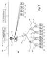
- FIG. 1is a block diagram overview illustration of an exemplary Advanced Metering System (AMS) or Infrastructure (AMI) deployment incorporating various of both apparatus and methodology aspects of the present subject matter;
- AMSAdvanced Metering System
- AMIInfrastructure
- FIG. 2illustrates for further background discussion purposes a block diagram of an exemplary watthour meter incorporating features in accordance with present ANSI watthour meter configuration standards
- FIG. 3illustrates for further background discussion purposes a block diagram of an exemplary watthour meter incorporating features in accordance with an alternative arrangement of an exemplary watthour meter configuration
- FIG. 4illustrates for further disclosure purposes relating to present subject matter a block diagram of an exemplary watthour meter incorporating features in accordance with present ANSI watthour meter configuration standards, incorporating remote disconnect features, and further incorporating subject matter of the presently disclosed technology relative to load side voltage sensing and related present features.
- the present subject matteris particularly concerned with the provision of improved corresponding apparatus and methodologies allowing enhanced functionality of metrology devices in an open operational framework. More particularly, the present technology relates to methodologies and apparatus for providing load side voltage sensing for utility meters which preferably are operable with remote disconnect features in an Advanced Metering Infrastructure (AMI) open operational framework.
- AMIAdvanced Metering Infrastructure
- FIG. 1is a block diagram overview illustration of an exemplary Advanced Metering System (AMS) or Infrastructure (AMI) deployment 100 generally in accordance with the present subject matter incorporating various of both apparatus and methodology aspects of the present subject matter.
- AMSAdvanced Metering System
- AMIInfrastructure
- AMS 100in pertinent part is preferably designed and built around industry standard protocols and transports, and therefore is intended to work with standards compliant components from third parties.
- AMS 100is configured to be transparent in a transportation context, such that the exemplary respective meters may be interrogated (such as using representative Collection Engine generally 190 ) regardless of what network infrastructure exists inbetween or among such components.
- the respective meterspreferably may also respond to Collection Engine 190 in the same manner.
- Collection Engine 190is capable of integrating Radio, PLC (Power Line Communications), and IP (Internet Protocol) connected meters, details of which communications form no particular aspects of the present subject matter.
- the system represented in present FIG. 1provides full two-way messaging to every device.
- the respectively represented meter devicesmay be variously configured to provide differing communications capabilities.
- one or more of GPRS, Ethernet, and RF LAN communications modulesmay be provided.
- GPRSwill allow meters to be IP addressable over a public backhaul and provide more bandwidth than the meter will likely ever require, but may incur ongoing subscription costs.
- Ethernet connectivitycan be used to bridge to third party technologies, including WiFi, WiMax, in-home gateways, and BPL (Broadband over Power Lines), without integrating any of these technologies directly into the metering device, but with the tradeoff of requiring external wiring and a two part solution.
- Ethernet devicesmay be used primarily in pilots and other special applications, and they additionally may be ideal for certain high-density RF-intolerant environments, such as meter closets. Due to the increased complexity of managing certain interfaces, for example, such as a WAN interface, with its more sophisticated link negotiation requirements and TCP/IP (Transmission Control Protocol/Internet Protocol) stack, WAN connected meters may include an additional circuit board dedicated to WAN connectivity. All such alternative and exemplary supporting boards, if required, are considered to be part of preferred embodiments that sense and communicate control and information data in accordance with the present subject matter, whether using ANSI standard C12.22 communications protocol or otherwise.
- TCP/IPTransmission Control Protocol/Internet Protocol
- the representative exemplary meter devices of present FIG. 1are intended to represent meter devices associated respectively with remote disconnect (and re-connect) functionality, as well as other present features relative to load side voltage sensing and related features.
- the Wide-Area-Networkis a fully routable, addressable, IP network that may involve a variety of different technologies including, but not limited to, GPRS, WiFi, WiMax, Fiber, Private Ethernet, BPL, or any other connection with sufficiently high bandwidth and ability to support full two-way IP communication.
- IP WANInternet Protocol
- Collection Engine 190is preferably implemented so as to be able to communicate directly with other respective nodes on the IP WAN. While communications may be conducted through a firewall 194 , it is not necessary that such be proxied, unless the proxy is itself a C12.22 node functioning as a relay between a private IP network and the public IP WAN.
- the Advanced Metering Systemas used in conjunction with the present technology provides a series (or plurality) of services (functionalities) to utilities. Beyond its most basic implementation (daily feeds of residential interval or TOU (Time of Use) data), it may provide power outage and restoration notifications, on-demand readings, firmware updates, load control/demand response, gas meter readings, and in-home display messages. All of such functions (services) may be preferably communicated via the ANSI standard C12.22 protocol.
- AMSAdvanced Metering System
- FIG. 2illustrates for further background discussion purposes a block diagram of a representative exemplary watthour meter generally 200 incorporating features in accordance with present ANSI watthour meter configuration standards.
- FIG. 3illustrates for further background discussion purposes a block diagram of a representative exemplary watthour meter generally 300 incorporating features in accordance with an alternative arrangement of an exemplary watthour meter configuration.
- the burden in the voltmeter portion generally 210is not measured, and hence any resulting watt losses would be incurred by the utility supplying service to such meter 300 .
- FIG. 4illustrates for further disclosure purposes relating to present subject matter a block diagram of an exemplary watthour meter generally 400 incorporating features in accordance with present ANSI watthour meter configuration standards, incorporating remote disconnect features generally 450 , and further incorporating subject matter of the presently disclosed technology relative to load side voltage sensing and related present features. It is also to be understood by those of ordinary skill in the art that the description herewith of an exemplary meter 400 in accordance with present subject matter is likewise a description of the representative meters variously illustrated in present FIG. 1 . It is also to be understood that in some implementations of the present subject matter, not all of the meters utilized in a particular arrangement must conform with all or a particular subset of the features presently described, as some meters in an arrangement may practice the present subject matter while some do not.
- the present subject matterutilizes a detection circuit or means generally 460 , which is situated generally downstream of the RDS 450 .
- Such detection circuit or means 460has a primary purpose and/or function of being able to sense whether voltage exists or doesn't exist at such relatively downstream, or load side location.
- the present exemplary arrangementsprovide a mechanism for using, for example, firmware-based correction of the metering offset caused by any burden of the detection circuit generally 460 .
- burdenwould be billed to the customer, but the present technology advantageously permits such cost to be redirected so as to be born by the utility.
- a meter fabricated in accordance with the present subject matterwill provide a built in correction for such usage burden.
- One possible implementation of the present subject matteris to compare the phase angle of the line side voltage generally 430 to the load side voltage 440 (which, of course, under normal disconnect conditions, should not exist). If such compared angle is changing, then the load side generally 440 is likely powered by a stand-alone generator, which would normally mean that there are no fraudulent practices involved. However, if the voltage angles remain synchronized (that is, they are not changing), then power is coming from a common source, which should mean the utility supplying the line or source side generally 430 . However, there are at least two possible ways for such utility source to be involved. One would be from a customer's neighbor (which could be legally obtained or possibly illegally obtained). Another possibility would be from some sort of by-pass arrangement (which would be improper, illegal, or fraudulent). Therefore, synchronized voltage angles would typically merit further investigation by the utility to determine whether there were some improper activities involved.
- FIG. 4An idealized (that is, simplified) version of a present exemplary voltage detection circuit 460 is shown in FIG. 4 .
- the representative capacitor generally 470is used to drop 60 Hz voltage.
- the representative resistor 480generally is used to prevent over-current during surges.
- the representative LED generally 490is part of an opto-isolator that prevents line generally 430 and load generally 440 from being tied together whenever RDS 450 is opened.
- a TVSis often basically a form of back to back zener diode, and it is where most of the watts loss occurs.
- the meter generally 400is calibrated so-called closed link (well known to one of ordinary skill in the art), then the afore-mentioned load would be metered by the utility, but not by any standard instrument or equipment (if phantom loaded).
- the current flowing in the detection circuit generally 460is supplied by the voltage source, the same as the potential sense circuit, and the power supply (the last 2 elements are not metered by the meter, however, as they are before the current circuits, as stated above).
- the described losswill be calibrated out of the meter at the test point, but will show as an offset, which will not be calibrated out.
- Open linkignores the aforementioned loss, while closed link does not. Thought of another way, closed link will always show the meter “slower” (to use the language of the old mechanical meter pictured as having a rotating dial, the speed of which reflects the rate of consumption of the measured commodity, such as electricity).
- Amount of errorThis is 0.3 W.
Landscapes
- Physics & Mathematics (AREA)
- General Physics & Mathematics (AREA)
- Engineering & Computer Science (AREA)
- Power Engineering (AREA)
- Arrangements For Transmission Of Measured Signals (AREA)
- Telephonic Communication Services (AREA)
- Selective Calling Equipment (AREA)
- Measurement Of Current Or Voltage (AREA)
Abstract
Description
Claims (24)
Priority Applications (5)
| Application Number | Priority Date | Filing Date | Title |
|---|---|---|---|
| US11/897,956US8049642B2 (en) | 2006-09-05 | 2007-08-31 | Load side voltage sensing for AMI metrology |
| PCT/US2007/019268WO2008030416A2 (en) | 2006-09-05 | 2007-09-04 | Load side voltage sensing for ami metrology |
| MX2009002416AMX2009002416A (en) | 2006-09-05 | 2007-09-04 | Load side voltage sensing for ami metrology. |
| CA2662072ACA2662072C (en) | 2006-09-05 | 2007-09-04 | Load side voltage sensing for ami metrology |
| BRPI0716165-4A2ABRPI0716165A2 (en) | 2006-09-05 | 2007-09-04 | lateral load stress detecting metrology, ami |
Applications Claiming Priority (2)
| Application Number | Priority Date | Filing Date | Title |
|---|---|---|---|
| US84226906P | 2006-09-05 | 2006-09-05 | |
| US11/897,956US8049642B2 (en) | 2006-09-05 | 2007-08-31 | Load side voltage sensing for AMI metrology |
Publications (2)
| Publication Number | Publication Date |
|---|---|
| US20080088296A1 US20080088296A1 (en) | 2008-04-17 |
| US8049642B2true US8049642B2 (en) | 2011-11-01 |
Family
ID=39157782
Family Applications (1)
| Application Number | Title | Priority Date | Filing Date |
|---|---|---|---|
| US11/897,956Active2030-08-31US8049642B2 (en) | 2006-09-05 | 2007-08-31 | Load side voltage sensing for AMI metrology |
Country Status (5)
| Country | Link |
|---|---|
| US (1) | US8049642B2 (en) |
| BR (1) | BRPI0716165A2 (en) |
| CA (1) | CA2662072C (en) |
| MX (1) | MX2009002416A (en) |
| WO (1) | WO2008030416A2 (en) |
Cited By (9)
| Publication number | Priority date | Publication date | Assignee | Title |
|---|---|---|---|---|
| US20080094248A1 (en)* | 2006-10-19 | 2008-04-24 | Lakich Daniel M | Extending contact life in remote disconnect applications |
| US20120078546A1 (en)* | 2010-09-28 | 2012-03-29 | Maxim Integrated Products, Inc. | Load-side voltage detection via electric metering processing |
| US8842712B2 (en) | 2011-03-24 | 2014-09-23 | Gregory C. Hancock | Methods and apparatuses for reception of frequency-hopping spread spectrum radio transmissions |
| US20150309094A1 (en)* | 2014-04-25 | 2015-10-29 | Loris Morassutto | System and method for measuring active power in a load without a load voltage |
| US9793716B2 (en) | 2014-04-24 | 2017-10-17 | Elster Solutions, Llc | Power meter disconnect switch operation |
| US10637241B2 (en)* | 2015-11-18 | 2020-04-28 | Seyed Ali Nabavi Niaki | System and method for intelligent static transfer switch with smart home power management |
| US10998731B2 (en) | 2016-05-26 | 2021-05-04 | Landis+Gyr Innovations, Inc. | Utility meter for use with distributed generation device |
| US11187734B2 (en) | 2019-05-31 | 2021-11-30 | Landis+Gyr Innovations, Inc. | Systems for electrically connecting metering devices and distributed energy resource devices |
| US11237194B2 (en) | 2019-10-11 | 2022-02-01 | Landis+Gyr Innovations, Inc. | Meter for use with a distributed energy resource device |
Families Citing this family (6)
| Publication number | Priority date | Publication date | Assignee | Title |
|---|---|---|---|---|
| US8212687B2 (en)* | 2006-09-15 | 2012-07-03 | Itron, Inc. | Load side voltage sensing for AMI metrology |
| US9000945B2 (en) | 2010-11-23 | 2015-04-07 | Corinex Communications Corp. | System and method for communicating over power lines |
| US8737493B2 (en)* | 2011-10-18 | 2014-05-27 | Itron, Inc. | Dual-channel receiver for powerline communications |
| US9099845B2 (en) | 2012-04-23 | 2015-08-04 | Thomas & Betts International, Inc. | Meter socket with current bypass |
| US9197062B2 (en) | 2012-12-17 | 2015-11-24 | Itron, Inc. | Remote disconnect safety mechanism |
| USD703562S1 (en) | 2013-01-16 | 2014-04-29 | Thomas & Betts International, Inc. | Meter socket cabinet |
Citations (132)
| Publication number | Priority date | Publication date | Assignee | Title |
|---|---|---|---|---|
| US4799062A (en) | 1987-04-27 | 1989-01-17 | Axonn Corporation | Radio position determination method and apparatus |
| US4977577A (en) | 1988-11-02 | 1990-12-11 | Axonn Corporation | Wireless alarm system |
| US4998102A (en) | 1988-08-02 | 1991-03-05 | Distribution Control Systems, Inc. | Integrated meter transponder |
| US5067136A (en) | 1988-11-02 | 1991-11-19 | Axonn Corporation | Wireless alarm system |
| US5095493A (en) | 1988-11-02 | 1992-03-10 | Axonn Corporation | Wireless alarm system |
| US5119396A (en) | 1990-08-27 | 1992-06-02 | Axonn Corporation | Binary phase shift keying modulation system |
| US5198796A (en) | 1991-06-27 | 1993-03-30 | Distribution Control Systems, Inc. | Outbound signal detector system and method |
| US5311541A (en) | 1992-05-08 | 1994-05-10 | Axonn Corporation | Frequency agile radio |
| US5310075A (en) | 1992-11-27 | 1994-05-10 | Distribution Control Systems, Inc. | Waterproof, gasketless enclosure |
| US5377222A (en) | 1992-05-08 | 1994-12-27 | Axonn Corporation | Frequency agile radio |
| US5377232A (en) | 1992-01-09 | 1994-12-27 | Cellnet Data Systems, Inc. | Frequency synchronized bidirectional radio system |
| US5422565A (en) | 1991-08-06 | 1995-06-06 | Schlumberger Industries, Inc. | Method and system for sensing removal of a utility meter from its socket |
| US5457713A (en) | 1994-03-07 | 1995-10-10 | Sanconix, Inc. | Spread spectrum alignment repositioning method |
| US5486805A (en) | 1993-07-06 | 1996-01-23 | Distribution Control Systems, Inc. | Method of receiving unsolicited messages on an electrical distribution network communications system |
| US5604768A (en) | 1992-01-09 | 1997-02-18 | Cellnet Data Systems, Inc. | Frequency synchronized bidirectional radio system |
| US5626755A (en) | 1995-11-08 | 1997-05-06 | Micronair, Inc. | Method and apparatus for waste digestion using multiple biological processes |
| US5661750A (en) | 1995-06-06 | 1997-08-26 | Cellnet Data Systems, Inc. | Direct sequence spread spectrum system |
| US5668828A (en) | 1992-05-08 | 1997-09-16 | Sanconix, Inc. | Enhanced frequency agile radio |
| US5696441A (en) | 1994-05-13 | 1997-12-09 | Distribution Control Systems, Inc. | Linear alternating current interface for electronic meters |
| USRE35829E (en) | 1990-08-27 | 1998-06-23 | Axonn Corporation | Binary phase shift keying modulation system and/or frequency multiplier |
| US5920589A (en) | 1995-06-07 | 1999-07-06 | Sanconix Inc. | Direct sequence spread spectrum DSP system |
| US5926531A (en) | 1997-02-14 | 1999-07-20 | Statsignal Systems, Inc. | Transmitter for accessing pay-type telephones |
| US5933072A (en) | 1997-11-07 | 1999-08-03 | Distribution Control Systems, Inc. | Current level control for TWACS inbound communications |
| US5940009A (en) | 1997-09-08 | 1999-08-17 | Abb Power T&D Company Inc. | Apparatus and method to detect tampering with an electronic utility meter |
| US5953368A (en) | 1988-11-02 | 1999-09-14 | Axonn Corporation | Wireless alarm system |
| US6028522A (en) | 1998-10-14 | 2000-02-22 | Statsignal Systems, Inc. | System for monitoring the light level around an ATM |
| US6044062A (en) | 1996-12-06 | 2000-03-28 | Communique, Llc | Wireless network system and method for providing same |
| US6047016A (en) | 1997-06-23 | 2000-04-04 | Cellnet Data Systems, Inc. | Processing a spread spectrum signal in a frequency adjustable system |
| US6100816A (en) | 1998-01-16 | 2000-08-08 | Cellnet Data Systems, Inc. | Utility meter adapter |
| US6163276A (en) | 1999-05-17 | 2000-12-19 | Cellnet Data Systems, Inc. | System for remote data collection |
| US6178197B1 (en) | 1997-06-23 | 2001-01-23 | Cellnet Data Systems, Inc. | Frequency discrimination in a spread spectrum signal processing system |
| US6181258B1 (en) | 1999-05-17 | 2001-01-30 | Cellnet Data Systems, Inc. | Receiver capable of parallel demodulation of messages |
| US6195018B1 (en) | 1996-02-07 | 2001-02-27 | Cellnet Data Systems, Inc. | Metering system |
| US6218953B1 (en) | 1998-10-14 | 2001-04-17 | Statsignal Systems, Inc. | System and method for monitoring the light level around an ATM |
| US6233327B1 (en) | 1997-02-14 | 2001-05-15 | Statsignal Systems, Inc. | Multi-function general purpose transceiver |
| US6232885B1 (en) | 1998-10-15 | 2001-05-15 | Schlumberger Resource Management Services, Inc. | Electricity meter |
| US6236197B1 (en) | 1998-05-15 | 2001-05-22 | Abb Power T&D Company Inc. | Apparatus and method for detecting tampering in a multiphase meter |
| US6246677B1 (en) | 1996-09-06 | 2001-06-12 | Innovatec Communications, Llc | Automatic meter reading data communication system |
| US6263009B1 (en) | 1997-06-23 | 2001-07-17 | Cellnet Data Systems, Inc. | Acquiring a spread spectrum signal |
| US20020019725A1 (en) | 1998-10-14 | 2002-02-14 | Statsignal Systems, Inc. | Wireless communication networks for providing remote monitoring of devices |
| US6363057B1 (en) | 1997-02-12 | 2002-03-26 | Abb Automation Inc. | Remote access to electronic meters using a TCP/IP protocol suite |
| US6369769B1 (en) | 2000-02-25 | 2002-04-09 | Innovatec Communications, Llc | Flush mounted pit lid antenna |
| US6377609B1 (en) | 1999-03-05 | 2002-04-23 | Neptune Technology Group Inc. | Spread spectrum frequency hopping system and method |
| US6424270B1 (en) | 1998-10-30 | 2002-07-23 | Schlumberger Resource Management Services, Inc. | Utility meter interface unit |
| US6426027B1 (en) | 2000-05-17 | 2002-07-30 | Neptune Technology Group, Inc. | Method of injection molding for creating a fluid meter housing |
| US6430268B1 (en) | 1997-09-20 | 2002-08-06 | Statsignal Systems, Inc. | Systems for requesting service of a vending machine |
| US6437692B1 (en) | 1998-06-22 | 2002-08-20 | Statsignal Systems, Inc. | System and method for monitoring and controlling remote devices |
| US6452986B1 (en) | 1999-05-17 | 2002-09-17 | Cellnet Data Systems, Inc. | Detector tolerant of frequency misalignment |
| US6456644B1 (en) | 1997-06-23 | 2002-09-24 | Cellnet Data Systems, Inc. | Bandpass correlation of a spread spectrum signal |
| US20020146985A1 (en) | 2001-01-31 | 2002-10-10 | Axonn Corporation | Battery operated remote transceiver (BORT) system and method |
| US20020169643A1 (en) | 2001-05-11 | 2002-11-14 | Statsignal Systems, Inc. | System and method for remotely processing reservations |
| US20030048199A1 (en) | 2001-09-13 | 2003-03-13 | Shimon Zigdon | Modular wireless fixed network for wide-area metering data collection and meter module apparatus |
| US6538577B1 (en) | 1997-09-05 | 2003-03-25 | Silver Springs Networks, Inc. | Electronic electric meter for networked meter reading |
| US20030063723A1 (en) | 2001-09-28 | 2003-04-03 | Derek Booth | Interactive system for managing and remotely connecting customer utility loads |
| US20030078029A1 (en) | 2001-10-24 | 2003-04-24 | Statsignal Systems, Inc. | System and method for transmitting an emergency message over an integrated wireless network |
| US20030093484A1 (en) | 2001-10-30 | 2003-05-15 | Petite Thomas D. | System and method for tansmitting pollution information over an integrated wireless network |
| US20030103486A1 (en) | 2001-11-30 | 2003-06-05 | Metin Salt | Time synchronization using dynamic thresholds |
| US6604434B1 (en) | 2000-06-23 | 2003-08-12 | Neptune Technology Group, Inc. | Method and apparatus for determining the direction and rate of a rotating element |
| US6612188B2 (en) | 2001-01-03 | 2003-09-02 | Neptune Technology Group Inc. | Self-powered fluid meter |
| US6617976B2 (en) | 1998-09-02 | 2003-09-09 | Neptune Technology Group, Inc. | Utility meter pit lid mounted antenna antenna assembly and method |
| US6617879B1 (en) | 1997-09-17 | 2003-09-09 | Sony Corporation | Transparently partitioned communication bus for multi-port bridge for a local area network |
| US6618578B1 (en) | 1997-02-14 | 2003-09-09 | Statsignal Systems, Inc | System and method for communicating with a remote communication unit via the public switched telephone network (PSTN) |
| US20030179149A1 (en) | 2001-11-26 | 2003-09-25 | Schlumberger Electricity, Inc. | Embedded antenna apparatus for utility metering applications |
| US6626048B1 (en) | 1998-09-29 | 2003-09-30 | Sensus Technologies Inc. | Magnetic flow meter |
| US6628764B1 (en) | 1997-02-14 | 2003-09-30 | Statsignal Systems, Inc. | System for requesting service of a vending machine |
| US6639939B1 (en) | 1997-05-20 | 2003-10-28 | Axonn L.L.C. | Direct sequence spread spectrum method computer-based product apparatus and system tolerant to frequency reference offset |
| US6650249B2 (en) | 1998-05-01 | 2003-11-18 | Elster Electricity, Llc | Wireless area network communications module for utility meters |
| US6657552B2 (en) | 2001-05-04 | 2003-12-02 | Invensys Metering Systems-North America Inc. | System and method for communicating and control of automated meter reading |
| US6671586B2 (en) | 2001-08-15 | 2003-12-30 | Statsignal Systems, Inc. | System and method for controlling power demand over an integrated wireless network |
| US20040004555A1 (en) | 2002-07-03 | 2004-01-08 | Schlumbergersema Inc. | Field selectable communication network |
| US20040008663A1 (en) | 2000-12-29 | 2004-01-15 | Devabhaktuni Srikrishna | Selection of routing paths based upon path quality of a wireless mesh network |
| US6700902B1 (en) | 1998-10-19 | 2004-03-02 | Elster Electricity, Llc | Method and system for improving wireless data packet delivery |
| US20040040368A1 (en) | 2002-09-04 | 2004-03-04 | Guckenberger Carl R. | Apparatus and method for quantity meter testing |
| US6704301B2 (en) | 2000-12-29 | 2004-03-09 | Tropos Networks, Inc. | Method and apparatus to provide a routing protocol for wireless devices |
| US20040053639A1 (en) | 1997-02-14 | 2004-03-18 | Petite Thomas D. | System and method for communicating with a remote communication unit via the public switched telephone network (PSTN) |
| US20040061623A1 (en) | 2002-06-10 | 2004-04-01 | Mohammad Tootoonian Mashhad | Adapter for a meter |
| US20040062224A1 (en) | 1996-12-06 | 2004-04-01 | Brownrigg Edwin B. | Wireless network system and method for providing same |
| US6734663B2 (en) | 2001-07-27 | 2004-05-11 | Invensys Metering Systems - North America Inc. | Solid-state electricity meter |
| US6747557B1 (en) | 1999-03-18 | 2004-06-08 | Statsignal Systems, Inc. | System and method for signaling a weather alert condition to a residential environment |
| US20040131125A1 (en) | 2001-03-30 | 2004-07-08 | Advanced Metering Data Comm. Systems, L.L.C. | Enhanced wireless packet data communication system, method, and apparatus applicable to both wide area networks and local area networks |
| US6784807B2 (en) | 2001-02-09 | 2004-08-31 | Statsignal Systems, Inc. | System and method for accurate reading of rotating disk |
| US6792337B2 (en) | 1994-12-30 | 2004-09-14 | Power Measurement Ltd. | Method and system for master slave protocol communication in an intelligent electronic device |
| US20040183687A1 (en) | 1999-03-18 | 2004-09-23 | Petite Thomas D. | System and method for signaling a weather alert condition to a residential environment |
| US20040192415A1 (en) | 2003-03-25 | 2004-09-30 | Silver Spring Networks, Inc. | Wireless communication system |
| US6816538B2 (en) | 2002-06-26 | 2004-11-09 | Elster Electricity, Llc | Frequency hopping spread spectrum decoder |
| US6836737B2 (en) | 2000-08-09 | 2004-12-28 | Statsignal Systems, Inc. | Systems and methods for providing remote monitoring of consumption for a utility meter |
| US6836108B1 (en) | 2003-11-03 | 2004-12-28 | M & Fc Holding, Llc | Three-phase electricity meter including integral test switch |
| US20040264379A1 (en) | 2000-12-29 | 2004-12-30 | Devabhaktuni Srikrishna | Multi-channel mesh network |
| US20040264435A1 (en) | 2003-06-24 | 2004-12-30 | Amalavoyal Chari | Method of wireless accessing |
| US6850197B2 (en) | 2003-01-31 | 2005-02-01 | M&Fc Holding, Llc | Printed circuit board antenna structure |
| US20050024235A1 (en) | 2002-06-27 | 2005-02-03 | Elster Electricity, Llc | Dynamic self-configuring metering network |
| US20050036487A1 (en) | 2003-08-13 | 2005-02-17 | Devabhaktuni Srikrishna | Method and apparatus for monitoring and displaying routing metrics of a network |
| US6859186B2 (en) | 2003-02-03 | 2005-02-22 | Silver Spring Networks, Inc. | Flush-mounted antenna and transmission system |
| US20050043860A1 (en) | 2001-08-15 | 2005-02-24 | Petite Thomas D. | System and method for controlling generation over an integrated wireless network |
| US20050052290A1 (en) | 2003-09-08 | 2005-03-10 | Axonn L.L.C. | Location monitoring and transmitting device, method, and computer program product using a simplex satellite transmitter |
| US20050052328A1 (en) | 2003-09-08 | 2005-03-10 | De Angelis Robert Hugo | Meter antenna |
| US6867707B1 (en) | 2002-04-24 | 2005-03-15 | Elster Electricity, Llc | Automated on-site meter registration confirmation using a portable, wireless computing device |
| US20050068970A1 (en) | 2000-12-29 | 2005-03-31 | Devabhaktuni Srikrishna | Determining bidirectional path quality within a wireless mesh network |
| US20050074015A1 (en) | 2003-06-24 | 2005-04-07 | Tropos Networks, Inc. | Method of subnet roaming within a network |
| US6885309B1 (en) | 2000-06-01 | 2005-04-26 | Cellnet Innovations, Inc. | Meter to internet pathway |
| US6891838B1 (en) | 1998-06-22 | 2005-05-10 | Statsignal Ipc, Llc | System and method for monitoring and controlling residential devices |
| US6900737B1 (en) | 1997-02-12 | 2005-05-31 | Elster Electricity, Llc | Remote access to electronic meters using the short message service |
| US6914533B2 (en) | 1998-06-22 | 2005-07-05 | Statsignal Ipc Llc | System and method for accessing residential monitoring devices |
| US6914893B2 (en) | 1998-06-22 | 2005-07-05 | Statsignal Ipc, Llc | System and method for monitoring and controlling remote devices |
| US20050147097A1 (en) | 2004-01-05 | 2005-07-07 | Amalavoyal Chari | Link layer emulation |
| US6918311B2 (en) | 2000-09-22 | 2005-07-19 | M&Fc Holding, Llc | Weather resistant automatic meter reading unit |
| US20050163144A1 (en) | 2001-03-26 | 2005-07-28 | Tropos Networks, Inc. | Assignment of channels to links of nodes within a mesh network |
| US20050172024A1 (en) | 2004-01-26 | 2005-08-04 | Tantalus Systems Corp. | Communications system |
| US20050169020A1 (en) | 2004-02-03 | 2005-08-04 | Knill Alex C. | Power supply for use in an electronic energy meter |
| US6931445B2 (en) | 2003-02-18 | 2005-08-16 | Statsignal Systems, Inc. | User interface for monitoring remote devices |
| US6940396B2 (en) | 2003-05-06 | 2005-09-06 | Distribution Control Systems, Inc. | Concurrent phase communication in TWACS |
| US20050195768A1 (en) | 2004-03-03 | 2005-09-08 | Petite Thomas D. | Method for communicating in dual-modes |
| US20050195775A1 (en) | 2004-03-03 | 2005-09-08 | Petite Thomas D. | System and method for monitoring remote devices with a dual-mode wireless communication protocol |
| US20050218873A1 (en) | 2004-04-05 | 2005-10-06 | Elster Electricity, Llc | Switching regulator with reduced conducted emissions |
| US20050226179A1 (en) | 2004-04-08 | 2005-10-13 | Cyrus Behroozi | Minimization of channel filters within wireless access nodes |
| US20050251401A1 (en) | 2004-05-10 | 2005-11-10 | Elster Electricity, Llc. | Mesh AMR network interconnecting to mesh Wi-Fi network |
| US20050251403A1 (en) | 2004-05-10 | 2005-11-10 | Elster Electricity, Llc. | Mesh AMR network interconnecting to TCP/IP wireless mesh network |
| US6972555B2 (en) | 2004-02-05 | 2005-12-06 | M&Fc Holding, Llc | Electronic electricity meter having configurable contacts |
| US20050271006A1 (en) | 2004-06-03 | 2005-12-08 | Amalavoyal Chari | Channel assignments within a mesh network |
| US20050278440A1 (en) | 2004-06-15 | 2005-12-15 | Elster Electricity, Llc. | System and method of visualizing network layout and performance characteristics in a wireless network |
| US6982651B2 (en) | 2001-05-02 | 2006-01-03 | M & Fc Holding, Llc | Automatic meter reading module |
| US20060002350A1 (en) | 2004-07-02 | 2006-01-05 | Cyrus Behroozi | Access point control of client roaming |
| US20060012935A1 (en) | 2004-07-13 | 2006-01-19 | Elster Electricity, Llc | Transient protector circuit for multi-phase energized power supplies |
| US20060018303A1 (en) | 2004-07-21 | 2006-01-26 | Sugiarto Ridwan Peter G | Wireless mesh network timed commit provisioning |
| US20060038548A1 (en) | 2004-08-17 | 2006-02-23 | Elster Electricity, Llc. | High voltage regulator for an electric meter power supply |
| US20060043961A1 (en) | 2002-06-27 | 2006-03-02 | Elster Electricity, Llc | Electrical-energy meter |
| US7023680B1 (en) | 2003-10-29 | 2006-04-04 | Psg Enterprises, Inc. | Transient voltage protection and ground status monitoring apparatus and method |
| US20060071812A1 (en) | 2002-06-28 | 2006-04-06 | Elster Electricity Llc | Data collector for an automated meter reading system |
| US20060071810A1 (en) | 2004-09-24 | 2006-04-06 | Elster Electricity, Llc. | System for automatically enforcing a demand reset in a fixed network of electricity meters |
| US20060091877A1 (en)* | 2004-10-19 | 2006-05-04 | Robinson Andrew J | Method and apparatus for an electric meter |
| US7046682B2 (en) | 1997-02-12 | 2006-05-16 | Elster Electricity, Llc. | Network-enabled, extensible metering system |
| US7091878B2 (en) | 2001-02-28 | 2006-08-15 | Landis+Gyr, Inc. | Electrical service disconnect having tamper detection |
- 2007
- 2007-08-31USUS11/897,956patent/US8049642B2/enactiveActive
- 2007-09-04CACA2662072Apatent/CA2662072C/enactiveActive
- 2007-09-04MXMX2009002416Apatent/MX2009002416A/enactiveIP Right Grant
- 2007-09-04BRBRPI0716165-4A2Apatent/BRPI0716165A2/ennot_activeIP Right Cessation
- 2007-09-04WOPCT/US2007/019268patent/WO2008030416A2/enactiveApplication Filing
Patent Citations (157)
| Publication number | Priority date | Publication date | Assignee | Title |
|---|---|---|---|---|
| US4799062A (en) | 1987-04-27 | 1989-01-17 | Axonn Corporation | Radio position determination method and apparatus |
| US4998102A (en) | 1988-08-02 | 1991-03-05 | Distribution Control Systems, Inc. | Integrated meter transponder |
| US5598427A (en) | 1988-11-02 | 1997-01-28 | Axonn Corporation | Wireless alarm system |
| US4977577A (en) | 1988-11-02 | 1990-12-11 | Axonn Corporation | Wireless alarm system |
| US5067136A (en) | 1988-11-02 | 1991-11-19 | Axonn Corporation | Wireless alarm system |
| US5095493A (en) | 1988-11-02 | 1992-03-10 | Axonn Corporation | Wireless alarm system |
| US5987058A (en) | 1988-11-02 | 1999-11-16 | Axonn Corporation | Wireless alarm system |
| US5953368A (en) | 1988-11-02 | 1999-09-14 | Axonn Corporation | Wireless alarm system |
| USRE35829E (en) | 1990-08-27 | 1998-06-23 | Axonn Corporation | Binary phase shift keying modulation system and/or frequency multiplier |
| US5119396A (en) | 1990-08-27 | 1992-06-02 | Axonn Corporation | Binary phase shift keying modulation system |
| US5265120A (en) | 1990-08-27 | 1993-11-23 | Axonn Corporation | Binary phase shift keying modulation system and/or frequency multiplier |
| US5198796A (en) | 1991-06-27 | 1993-03-30 | Distribution Control Systems, Inc. | Outbound signal detector system and method |
| US5422565A (en) | 1991-08-06 | 1995-06-06 | Schlumberger Industries, Inc. | Method and system for sensing removal of a utility meter from its socket |
| US5604768A (en) | 1992-01-09 | 1997-02-18 | Cellnet Data Systems, Inc. | Frequency synchronized bidirectional radio system |
| US5377232A (en) | 1992-01-09 | 1994-12-27 | Cellnet Data Systems, Inc. | Frequency synchronized bidirectional radio system |
| US6335953B1 (en) | 1992-05-08 | 2002-01-01 | Axonn, L.L.C. | Enhanced frequency agile radio |
| US6031883A (en) | 1992-05-08 | 2000-02-29 | Sanconix, Inc. | Enhanced frequency agile radio |
| US5668828A (en) | 1992-05-08 | 1997-09-16 | Sanconix, Inc. | Enhanced frequency agile radio |
| US5377222A (en) | 1992-05-08 | 1994-12-27 | Axonn Corporation | Frequency agile radio |
| US5311541A (en) | 1992-05-08 | 1994-05-10 | Axonn Corporation | Frequency agile radio |
| US5310075A (en) | 1992-11-27 | 1994-05-10 | Distribution Control Systems, Inc. | Waterproof, gasketless enclosure |
| US5486805A (en) | 1993-07-06 | 1996-01-23 | Distribution Control Systems, Inc. | Method of receiving unsolicited messages on an electrical distribution network communications system |
| US5457713A (en) | 1994-03-07 | 1995-10-10 | Sanconix, Inc. | Spread spectrum alignment repositioning method |
| US5696441A (en) | 1994-05-13 | 1997-12-09 | Distribution Control Systems, Inc. | Linear alternating current interface for electronic meters |
| US6792337B2 (en) | 1994-12-30 | 2004-09-14 | Power Measurement Ltd. | Method and system for master slave protocol communication in an intelligent electronic device |
| US5661750A (en) | 1995-06-06 | 1997-08-26 | Cellnet Data Systems, Inc. | Direct sequence spread spectrum system |
| US5920589A (en) | 1995-06-07 | 1999-07-06 | Sanconix Inc. | Direct sequence spread spectrum DSP system |
| US5626755A (en) | 1995-11-08 | 1997-05-06 | Micronair, Inc. | Method and apparatus for waste digestion using multiple biological processes |
| US6195018B1 (en) | 1996-02-07 | 2001-02-27 | Cellnet Data Systems, Inc. | Metering system |
| US6246677B1 (en) | 1996-09-06 | 2001-06-12 | Innovatec Communications, Llc | Automatic meter reading data communication system |
| US6044062A (en) | 1996-12-06 | 2000-03-28 | Communique, Llc | Wireless network system and method for providing same |
| US6249516B1 (en) | 1996-12-06 | 2001-06-19 | Edwin B. Brownrigg | Wireless network gateway and method for providing same |
| US20040062224A1 (en) | 1996-12-06 | 2004-04-01 | Brownrigg Edwin B. | Wireless network system and method for providing same |
| US7054271B2 (en) | 1996-12-06 | 2006-05-30 | Ipco, Llc | Wireless network system and method for providing same |
| US6747981B2 (en) | 1997-02-12 | 2004-06-08 | Elster Electricity, Llc | Remote access to electronic meters using a TCP/IP protocol suite |
| US7046682B2 (en) | 1997-02-12 | 2006-05-16 | Elster Electricity, Llc. | Network-enabled, extensible metering system |
| US6396839B1 (en) | 1997-02-12 | 2002-05-28 | Abb Automation Inc. | Remote access to electronic meters using a TCP/IP protocol suite |
| US6900737B1 (en) | 1997-02-12 | 2005-05-31 | Elster Electricity, Llc | Remote access to electronic meters using the short message service |
| US6363057B1 (en) | 1997-02-12 | 2002-03-26 | Abb Automation Inc. | Remote access to electronic meters using a TCP/IP protocol suite |
| US7126494B2 (en) | 1997-02-12 | 2006-10-24 | Elster Electricity, Llc | Remote access to electronic meters using a TCP/IP protocol suite |
| US20040218616A1 (en) | 1997-02-12 | 2004-11-04 | Elster Electricity, Llc | Remote access to electronic meters using a TCP/IP protocol suite |
| US6233327B1 (en) | 1997-02-14 | 2001-05-15 | Statsignal Systems, Inc. | Multi-function general purpose transceiver |
| US5926531A (en) | 1997-02-14 | 1999-07-20 | Statsignal Systems, Inc. | Transmitter for accessing pay-type telephones |
| US6618578B1 (en) | 1997-02-14 | 2003-09-09 | Statsignal Systems, Inc | System and method for communicating with a remote communication unit via the public switched telephone network (PSTN) |
| US6628764B1 (en) | 1997-02-14 | 2003-09-30 | Statsignal Systems, Inc. | System for requesting service of a vending machine |
| US20040053639A1 (en) | 1997-02-14 | 2004-03-18 | Petite Thomas D. | System and method for communicating with a remote communication unit via the public switched telephone network (PSTN) |
| US6639939B1 (en) | 1997-05-20 | 2003-10-28 | Axonn L.L.C. | Direct sequence spread spectrum method computer-based product apparatus and system tolerant to frequency reference offset |
| US6178197B1 (en) | 1997-06-23 | 2001-01-23 | Cellnet Data Systems, Inc. | Frequency discrimination in a spread spectrum signal processing system |
| US6047016A (en) | 1997-06-23 | 2000-04-04 | Cellnet Data Systems, Inc. | Processing a spread spectrum signal in a frequency adjustable system |
| US6456644B1 (en) | 1997-06-23 | 2002-09-24 | Cellnet Data Systems, Inc. | Bandpass correlation of a spread spectrum signal |
| US6263009B1 (en) | 1997-06-23 | 2001-07-17 | Cellnet Data Systems, Inc. | Acquiring a spread spectrum signal |
| US6538577B1 (en) | 1997-09-05 | 2003-03-25 | Silver Springs Networks, Inc. | Electronic electric meter for networked meter reading |
| US5940009A (en) | 1997-09-08 | 1999-08-17 | Abb Power T&D Company Inc. | Apparatus and method to detect tampering with an electronic utility meter |
| US6617879B1 (en) | 1997-09-17 | 2003-09-09 | Sony Corporation | Transparently partitioned communication bus for multi-port bridge for a local area network |
| US6430268B1 (en) | 1997-09-20 | 2002-08-06 | Statsignal Systems, Inc. | Systems for requesting service of a vending machine |
| US5933072A (en) | 1997-11-07 | 1999-08-03 | Distribution Control Systems, Inc. | Current level control for TWACS inbound communications |
| US6100816A (en) | 1998-01-16 | 2000-08-08 | Cellnet Data Systems, Inc. | Utility meter adapter |
| US6778099B1 (en) | 1998-05-01 | 2004-08-17 | Elster Electricity, Llc | Wireless area network communications module for utility meters |
| US6650249B2 (en) | 1998-05-01 | 2003-11-18 | Elster Electricity, Llc | Wireless area network communications module for utility meters |
| US6236197B1 (en) | 1998-05-15 | 2001-05-22 | Abb Power T&D Company Inc. | Apparatus and method for detecting tampering in a multiphase meter |
| US6891838B1 (en) | 1998-06-22 | 2005-05-10 | Statsignal Ipc, Llc | System and method for monitoring and controlling residential devices |
| US6914893B2 (en) | 1998-06-22 | 2005-07-05 | Statsignal Ipc, Llc | System and method for monitoring and controlling remote devices |
| US20050243867A1 (en) | 1998-06-22 | 2005-11-03 | Statsignal Ipc, Llc | Systems and methods for monitoring and controlling remote devices |
| US6437692B1 (en) | 1998-06-22 | 2002-08-20 | Statsignal Systems, Inc. | System and method for monitoring and controlling remote devices |
| US20050201397A1 (en) | 1998-06-22 | 2005-09-15 | Statsignal Ipc, Llc | Systems and methods for monitoring conditions |
| US20050190055A1 (en) | 1998-06-22 | 2005-09-01 | Statsignal Ipc, Llc | Smoke detection methods, devices, and systems |
| US6914533B2 (en) | 1998-06-22 | 2005-07-05 | Statsignal Ipc Llc | System and method for accessing residential monitoring devices |
| US6617976B2 (en) | 1998-09-02 | 2003-09-09 | Neptune Technology Group, Inc. | Utility meter pit lid mounted antenna antenna assembly and method |
| US6626048B1 (en) | 1998-09-29 | 2003-09-30 | Sensus Technologies Inc. | Magnetic flow meter |
| US6218953B1 (en) | 1998-10-14 | 2001-04-17 | Statsignal Systems, Inc. | System and method for monitoring the light level around an ATM |
| US20020019725A1 (en) | 1998-10-14 | 2002-02-14 | Statsignal Systems, Inc. | Wireless communication networks for providing remote monitoring of devices |
| US7103511B2 (en) | 1998-10-14 | 2006-09-05 | Statsignal Ipc, Llc | Wireless communication networks for providing remote monitoring of devices |
| US6028522A (en) | 1998-10-14 | 2000-02-22 | Statsignal Systems, Inc. | System for monitoring the light level around an ATM |
| US6617978B2 (en) | 1998-10-15 | 2003-09-09 | Schlumbergersema Inc. | Electricity meter |
| US6232885B1 (en) | 1998-10-15 | 2001-05-15 | Schlumberger Resource Management Services, Inc. | Electricity meter |
| US6700902B1 (en) | 1998-10-19 | 2004-03-02 | Elster Electricity, Llc | Method and system for improving wireless data packet delivery |
| US6424270B1 (en) | 1998-10-30 | 2002-07-23 | Schlumberger Resource Management Services, Inc. | Utility meter interface unit |
| US6377609B1 (en) | 1999-03-05 | 2002-04-23 | Neptune Technology Group Inc. | Spread spectrum frequency hopping system and method |
| US20040183687A1 (en) | 1999-03-18 | 2004-09-23 | Petite Thomas D. | System and method for signaling a weather alert condition to a residential environment |
| US6747557B1 (en) | 1999-03-18 | 2004-06-08 | Statsignal Systems, Inc. | System and method for signaling a weather alert condition to a residential environment |
| US6163276A (en) | 1999-05-17 | 2000-12-19 | Cellnet Data Systems, Inc. | System for remote data collection |
| US6452986B1 (en) | 1999-05-17 | 2002-09-17 | Cellnet Data Systems, Inc. | Detector tolerant of frequency misalignment |
| US6181258B1 (en) | 1999-05-17 | 2001-01-30 | Cellnet Data Systems, Inc. | Receiver capable of parallel demodulation of messages |
| US6369769B1 (en) | 2000-02-25 | 2002-04-09 | Innovatec Communications, Llc | Flush mounted pit lid antenna |
| US6426027B1 (en) | 2000-05-17 | 2002-07-30 | Neptune Technology Group, Inc. | Method of injection molding for creating a fluid meter housing |
| US6885309B1 (en) | 2000-06-01 | 2005-04-26 | Cellnet Innovations, Inc. | Meter to internet pathway |
| US6604434B1 (en) | 2000-06-23 | 2003-08-12 | Neptune Technology Group, Inc. | Method and apparatus for determining the direction and rate of a rotating element |
| US20050043059A1 (en) | 2000-08-09 | 2005-02-24 | Petite Thomas D. | Systems and methods for providing remote monitoring of electricity consumption for an electric meter |
| US6836737B2 (en) | 2000-08-09 | 2004-12-28 | Statsignal Systems, Inc. | Systems and methods for providing remote monitoring of consumption for a utility meter |
| US6918311B2 (en) | 2000-09-22 | 2005-07-19 | M&Fc Holding, Llc | Weather resistant automatic meter reading unit |
| US20040085928A1 (en) | 2000-12-29 | 2004-05-06 | Chari Amalayoyal Narasimha | Method and system to provide a routing protocol for wireless devices |
| US20050129005A1 (en) | 2000-12-29 | 2005-06-16 | Tropos Networks, Inc. | Selection of routing paths based upon path qualities of a wireless routes within a wireless mesh network |
| US6965575B2 (en) | 2000-12-29 | 2005-11-15 | Tropos Networks | Selection of routing paths based upon path quality of a wireless mesh network |
| US20050068970A1 (en) | 2000-12-29 | 2005-03-31 | Devabhaktuni Srikrishna | Determining bidirectional path quality within a wireless mesh network |
| US6704301B2 (en) | 2000-12-29 | 2004-03-09 | Tropos Networks, Inc. | Method and apparatus to provide a routing protocol for wireless devices |
| US20040008663A1 (en) | 2000-12-29 | 2004-01-15 | Devabhaktuni Srikrishna | Selection of routing paths based upon path quality of a wireless mesh network |
| US20040264379A1 (en) | 2000-12-29 | 2004-12-30 | Devabhaktuni Srikrishna | Multi-channel mesh network |
| US6612188B2 (en) | 2001-01-03 | 2003-09-02 | Neptune Technology Group Inc. | Self-powered fluid meter |
| US20020146985A1 (en) | 2001-01-31 | 2002-10-10 | Axonn Corporation | Battery operated remote transceiver (BORT) system and method |
| US6784807B2 (en) | 2001-02-09 | 2004-08-31 | Statsignal Systems, Inc. | System and method for accurate reading of rotating disk |
| US20050030199A1 (en) | 2001-02-09 | 2005-02-10 | Petite Thomas D. | System and method for accurate reading of rotating disk |
| US7091878B2 (en) | 2001-02-28 | 2006-08-15 | Landis+Gyr, Inc. | Electrical service disconnect having tamper detection |
| US20050163144A1 (en) | 2001-03-26 | 2005-07-28 | Tropos Networks, Inc. | Assignment of channels to links of nodes within a mesh network |
| US20040131125A1 (en) | 2001-03-30 | 2004-07-08 | Advanced Metering Data Comm. Systems, L.L.C. | Enhanced wireless packet data communication system, method, and apparatus applicable to both wide area networks and local area networks |
| US6982651B2 (en) | 2001-05-02 | 2006-01-03 | M & Fc Holding, Llc | Automatic meter reading module |
| US6657552B2 (en) | 2001-05-04 | 2003-12-02 | Invensys Metering Systems-North America Inc. | System and method for communicating and control of automated meter reading |
| US20020169643A1 (en) | 2001-05-11 | 2002-11-14 | Statsignal Systems, Inc. | System and method for remotely processing reservations |
| US6734663B2 (en) | 2001-07-27 | 2004-05-11 | Invensys Metering Systems - North America Inc. | Solid-state electricity meter |
| US6862498B2 (en) | 2001-08-15 | 2005-03-01 | Statsignal Systems, Inc. | System and method for controlling power demand over an integrated wireless network |
| US6671586B2 (en) | 2001-08-15 | 2003-12-30 | Statsignal Systems, Inc. | System and method for controlling power demand over an integrated wireless network |
| US20050043860A1 (en) | 2001-08-15 | 2005-02-24 | Petite Thomas D. | System and method for controlling generation over an integrated wireless network |
| US20040088083A1 (en) | 2001-08-15 | 2004-05-06 | James Davis | System and method for controlling power demand over an integrated wireless network |
| US20030048199A1 (en) | 2001-09-13 | 2003-03-13 | Shimon Zigdon | Modular wireless fixed network for wide-area metering data collection and meter module apparatus |
| US20030063723A1 (en) | 2001-09-28 | 2003-04-03 | Derek Booth | Interactive system for managing and remotely connecting customer utility loads |
| US20030078029A1 (en) | 2001-10-24 | 2003-04-24 | Statsignal Systems, Inc. | System and method for transmitting an emergency message over an integrated wireless network |
| US20030093484A1 (en) | 2001-10-30 | 2003-05-15 | Petite Thomas D. | System and method for tansmitting pollution information over an integrated wireless network |
| US20030179149A1 (en) | 2001-11-26 | 2003-09-25 | Schlumberger Electricity, Inc. | Embedded antenna apparatus for utility metering applications |
| US20030103486A1 (en) | 2001-11-30 | 2003-06-05 | Metin Salt | Time synchronization using dynamic thresholds |
| US6867707B1 (en) | 2002-04-24 | 2005-03-15 | Elster Electricity, Llc | Automated on-site meter registration confirmation using a portable, wireless computing device |
| US20040061623A1 (en) | 2002-06-10 | 2004-04-01 | Mohammad Tootoonian Mashhad | Adapter for a meter |
| US6816538B2 (en) | 2002-06-26 | 2004-11-09 | Elster Electricity, Llc | Frequency hopping spread spectrum decoder |
| US20050024235A1 (en) | 2002-06-27 | 2005-02-03 | Elster Electricity, Llc | Dynamic self-configuring metering network |
| US20060043961A1 (en) | 2002-06-27 | 2006-03-02 | Elster Electricity, Llc | Electrical-energy meter |
| US20060071812A1 (en) | 2002-06-28 | 2006-04-06 | Elster Electricity Llc | Data collector for an automated meter reading system |
| US20040004555A1 (en) | 2002-07-03 | 2004-01-08 | Schlumbergersema Inc. | Field selectable communication network |
| US20040040368A1 (en) | 2002-09-04 | 2004-03-04 | Guckenberger Carl R. | Apparatus and method for quantity meter testing |
| US6850197B2 (en) | 2003-01-31 | 2005-02-01 | M&Fc Holding, Llc | Printed circuit board antenna structure |
| US6859186B2 (en) | 2003-02-03 | 2005-02-22 | Silver Spring Networks, Inc. | Flush-mounted antenna and transmission system |
| US6931445B2 (en) | 2003-02-18 | 2005-08-16 | Statsignal Systems, Inc. | User interface for monitoring remote devices |
| US20040192415A1 (en) | 2003-03-25 | 2004-09-30 | Silver Spring Networks, Inc. | Wireless communication system |
| US6940396B2 (en) | 2003-05-06 | 2005-09-06 | Distribution Control Systems, Inc. | Concurrent phase communication in TWACS |
| US20050074015A1 (en) | 2003-06-24 | 2005-04-07 | Tropos Networks, Inc. | Method of subnet roaming within a network |
| US20040264435A1 (en) | 2003-06-24 | 2004-12-30 | Amalavoyal Chari | Method of wireless accessing |
| US20050036487A1 (en) | 2003-08-13 | 2005-02-17 | Devabhaktuni Srikrishna | Method and apparatus for monitoring and displaying routing metrics of a network |
| US20050052290A1 (en) | 2003-09-08 | 2005-03-10 | Axonn L.L.C. | Location monitoring and transmitting device, method, and computer program product using a simplex satellite transmitter |
| US20050171696A1 (en) | 2003-09-08 | 2005-08-04 | Axonn L.L.C. | Location monitoring and transmitting device, method, and computer program product using a simplex satellite transmitter |
| US20050052328A1 (en) | 2003-09-08 | 2005-03-10 | De Angelis Robert Hugo | Meter antenna |
| US7023680B1 (en) | 2003-10-29 | 2006-04-04 | Psg Enterprises, Inc. | Transient voltage protection and ground status monitoring apparatus and method |
| US6836108B1 (en) | 2003-11-03 | 2004-12-28 | M & Fc Holding, Llc | Three-phase electricity meter including integral test switch |
| US20050147097A1 (en) | 2004-01-05 | 2005-07-07 | Amalavoyal Chari | Link layer emulation |
| US20050172024A1 (en) | 2004-01-26 | 2005-08-04 | Tantalus Systems Corp. | Communications system |
| US20050169020A1 (en) | 2004-02-03 | 2005-08-04 | Knill Alex C. | Power supply for use in an electronic energy meter |
| US6972555B2 (en) | 2004-02-05 | 2005-12-06 | M&Fc Holding, Llc | Electronic electricity meter having configurable contacts |
| US20050195775A1 (en) | 2004-03-03 | 2005-09-08 | Petite Thomas D. | System and method for monitoring remote devices with a dual-mode wireless communication protocol |
| US20050195768A1 (en) | 2004-03-03 | 2005-09-08 | Petite Thomas D. | Method for communicating in dual-modes |
| US20050218873A1 (en) | 2004-04-05 | 2005-10-06 | Elster Electricity, Llc | Switching regulator with reduced conducted emissions |
| US20050226179A1 (en) | 2004-04-08 | 2005-10-13 | Cyrus Behroozi | Minimization of channel filters within wireless access nodes |
| US20050251403A1 (en) | 2004-05-10 | 2005-11-10 | Elster Electricity, Llc. | Mesh AMR network interconnecting to TCP/IP wireless mesh network |
| US20050251401A1 (en) | 2004-05-10 | 2005-11-10 | Elster Electricity, Llc. | Mesh AMR network interconnecting to mesh Wi-Fi network |
| US20050271006A1 (en) | 2004-06-03 | 2005-12-08 | Amalavoyal Chari | Channel assignments within a mesh network |
| US20050278440A1 (en) | 2004-06-15 | 2005-12-15 | Elster Electricity, Llc. | System and method of visualizing network layout and performance characteristics in a wireless network |
| US20060002350A1 (en) | 2004-07-02 | 2006-01-05 | Cyrus Behroozi | Access point control of client roaming |
| US20060012935A1 (en) | 2004-07-13 | 2006-01-19 | Elster Electricity, Llc | Transient protector circuit for multi-phase energized power supplies |
| US20060018303A1 (en) | 2004-07-21 | 2006-01-26 | Sugiarto Ridwan Peter G | Wireless mesh network timed commit provisioning |
| US20060038548A1 (en) | 2004-08-17 | 2006-02-23 | Elster Electricity, Llc. | High voltage regulator for an electric meter power supply |
| US20060071810A1 (en) | 2004-09-24 | 2006-04-06 | Elster Electricity, Llc. | System for automatically enforcing a demand reset in a fixed network of electricity meters |
| US20060091877A1 (en)* | 2004-10-19 | 2006-05-04 | Robinson Andrew J | Method and apparatus for an electric meter |
Non-Patent Citations (1)
| Title |
|---|
| International Search Report for PCT International Application No. PCT/US2007/019268; search completed Jan. 18, 2008. |
Cited By (17)
| Publication number | Priority date | Publication date | Assignee | Title |
|---|---|---|---|---|
| US20080094248A1 (en)* | 2006-10-19 | 2008-04-24 | Lakich Daniel M | Extending contact life in remote disconnect applications |
| US8384558B2 (en)* | 2006-10-19 | 2013-02-26 | Itron, Inc. | Extending contact life in remote disconnect applications |
| US20120078546A1 (en)* | 2010-09-28 | 2012-03-29 | Maxim Integrated Products, Inc. | Load-side voltage detection via electric metering processing |
| US8842712B2 (en) | 2011-03-24 | 2014-09-23 | Gregory C. Hancock | Methods and apparatuses for reception of frequency-hopping spread spectrum radio transmissions |
| US9793716B2 (en) | 2014-04-24 | 2017-10-17 | Elster Solutions, Llc | Power meter disconnect switch operation |
| US10236691B2 (en) | 2014-04-24 | 2019-03-19 | Honeywell International Inc. | Power meter disconnect switch operation |
| US20150309094A1 (en)* | 2014-04-25 | 2015-10-29 | Loris Morassutto | System and method for measuring active power in a load without a load voltage |
| US10161973B2 (en)* | 2014-04-25 | 2018-12-25 | Eurotherm Ltd | System and method for measuring active power in a load without a load voltage |
| US10637241B2 (en)* | 2015-11-18 | 2020-04-28 | Seyed Ali Nabavi Niaki | System and method for intelligent static transfer switch with smart home power management |
| US10998731B2 (en) | 2016-05-26 | 2021-05-04 | Landis+Gyr Innovations, Inc. | Utility meter for use with distributed generation device |
| US11223210B2 (en) | 2016-05-26 | 2022-01-11 | Landis+Gyr Innovations, Inc. | Utility meter for use with distributed generation device |
| US11187734B2 (en) | 2019-05-31 | 2021-11-30 | Landis+Gyr Innovations, Inc. | Systems for electrically connecting metering devices and distributed energy resource devices |
| US11774473B2 (en) | 2019-05-31 | 2023-10-03 | Landis+Gyr Technology, Inc. | Systems for electrically connecting metering devices and distributed energy resource devices |
| US11237194B2 (en) | 2019-10-11 | 2022-02-01 | Landis+Gyr Innovations, Inc. | Meter for use with a distributed energy resource device |
| US11506693B2 (en) | 2019-10-11 | 2022-11-22 | Landis+Gyr Innovations, Inc. | Meter and socket for use with a distributed energy resource device |
| US11835556B2 (en) | 2019-10-11 | 2023-12-05 | Landis+Gyr Technology, Inc. | Meter for use with a distributed energy resource device |
| US11965918B2 (en) | 2019-10-11 | 2024-04-23 | Landis+Gyr Technology, Inc. | Meter for use with a distributed energy resource device |
Also Published As
| Publication number | Publication date |
|---|---|
| WO2008030416A3 (en) | 2008-05-02 |
| CA2662072C (en) | 2017-02-28 |
| US20080088296A1 (en) | 2008-04-17 |
| WO2008030416A2 (en) | 2008-03-13 |
| MX2009002416A (en) | 2009-03-16 |
| BRPI0716165A2 (en) | 2013-09-17 |
| CA2662072A1 (en) | 2008-03-13 |
Similar Documents
| Publication | Publication Date | Title |
|---|---|---|
| US8212687B2 (en) | Load side voltage sensing for AMI metrology | |
| US8049642B2 (en) | Load side voltage sensing for AMI metrology | |
| US8384558B2 (en) | Extending contact life in remote disconnect applications | |
| EP1784804B1 (en) | Methods and systems for meter reading and high speed data transfer | |
| US20080074285A1 (en) | Interface between meter and application (IMA) | |
| Arif et al. | Experimental study and design of smart energy meter for the smart grid | |
| US20220205811A1 (en) | Metering assembly, switchboard case, adapter cradle and method of use | |
| US20090256686A1 (en) | Power line communication system and an intelligent meter | |
| US20070222636A1 (en) | System and method for a networked utility meter | |
| AU2014277983A1 (en) | Non-technical losses in a power distribution grid | |
| WO2008027455A2 (en) | Orchestration manager | |
| WO2012014039A2 (en) | Intelligent core engine | |
| WO2009137902A1 (en) | Individualized self-monitoring system for transformers in power measurement installations and method of self-monitoring and diagnosis of transformers in power measurement installations | |
| NZ530254A (en) | A power line communication system and an intelligent meter therefor | |
| GB2572379A (en) | A monitoring and protection device | |
| GB2466107A (en) | Smart utility metering system | |
| US8312103B2 (en) | Periodic balanced communication node and server assignment | |
| US20080071930A1 (en) | Native network transport | |
| NO329517B1 (en) | A system for the distribution of electrical energy | |
| OLADOSU et al. | ANALYTICAL MODELLING OF SINGLE PHASE SMART METER WITH REAL-TIME TAMPERING ALERT | |
| MXPA03009943A (en) | Improvements in an integral modular system for managing multiple subscribers in a service line, having elements for detecting fluid leakages/ steal. |
Legal Events
| Date | Code | Title | Description |
|---|---|---|---|
| AS | Assignment | Owner name:ITRON, INC., WASHINGTON Free format text:ASSIGNMENT OF ASSIGNORS INTEREST;ASSIGNORS:MAKINSON, DAVID N.;LANCASTER, ANDREW;SWANSON, SCOTT;REEL/FRAME:021357/0231;SIGNING DATES FROM 20071126 TO 20071128 Owner name:ITRON, INC., WASHINGTON Free format text:ASSIGNMENT OF ASSIGNORS INTEREST;ASSIGNORS:MAKINSON, DAVID N.;LANCASTER, ANDREW;SWANSON, SCOTT;SIGNING DATES FROM 20071126 TO 20071128;REEL/FRAME:021357/0231 | |
| AS | Assignment | Owner name:WELLS FARGO BANK, NATIONAL ASSOCIATION, WASHINGTON Free format text:SECURITY AGREEMENT;ASSIGNOR:ITRON, INC.;REEL/FRAME:026761/0069 Effective date:20110805 | |
| STCF | Information on status: patent grant | Free format text:PATENTED CASE | |
| AS | Assignment | Owner name:WELLS FARGO BANK, NATIONAL ASSOCIATION, WASHINGTON Free format text:SUPPLEMENTAL SECURITY AGREEMENT (PATENTS);ASSIGNOR:ITRON, INC.;REEL/FRAME:029564/0657 Effective date:20121121 | |
| FPAY | Fee payment | Year of fee payment:4 | |
| AS | Assignment | Owner name:WELLS FARGO BANK, NATIONAL ASSOCIATION, NORTH CAROLINA Free format text:SECURITY INTEREST;ASSIGNORS:ITRON, INC.;ITRON NETWORKED SOLUTIONS, INC.;REEL/FRAME:045017/0893 Effective date:20180105 Owner name:WELLS FARGO BANK, NATIONAL ASSOCIATION, NORTH CARO Free format text:SECURITY INTEREST;ASSIGNORS:ITRON, INC.;ITRON NETWORKED SOLUTIONS, INC.;REEL/FRAME:045017/0893 Effective date:20180105 | |
| MAFP | Maintenance fee payment | Free format text:PAYMENT OF MAINTENANCE FEE, 8TH YEAR, LARGE ENTITY (ORIGINAL EVENT CODE: M1552); ENTITY STATUS OF PATENT OWNER: LARGE ENTITY Year of fee payment:8 | |
| MAFP | Maintenance fee payment | Free format text:PAYMENT OF MAINTENANCE FEE, 12TH YEAR, LARGE ENTITY (ORIGINAL EVENT CODE: M1553); ENTITY STATUS OF PATENT OWNER: LARGE ENTITY Year of fee payment:12 |