US8049597B1 - Systems and methods for securely monitoring an individual - Google Patents
Systems and methods for securely monitoring an individualDownload PDFInfo
- Publication number
- US8049597B1 US8049597B1US12/563,933US56393309AUS8049597B1US 8049597 B1US8049597 B1US 8049597B1US 56393309 AUS56393309 AUS 56393309AUS 8049597 B1US8049597 B1US 8049597B1
- Authority
- US
- United States
- Prior art keywords
- individual
- biometric
- measurements
- monitoring
- profile
- Prior art date
- Legal status (The legal status is an assumption and is not a legal conclusion. Google has not performed a legal analysis and makes no representation as to the accuracy of the status listed.)
- Expired - Lifetime
Links
Images


Classifications
- H—ELECTRICITY
- H04—ELECTRIC COMMUNICATION TECHNIQUE
- H04L—TRANSMISSION OF DIGITAL INFORMATION, e.g. TELEGRAPHIC COMMUNICATION
- H04L63/00—Network architectures or network communication protocols for network security
- H04L63/08—Network architectures or network communication protocols for network security for authentication of entities
- G—PHYSICS
- G05—CONTROLLING; REGULATING
- G05B—CONTROL OR REGULATING SYSTEMS IN GENERAL; FUNCTIONAL ELEMENTS OF SUCH SYSTEMS; MONITORING OR TESTING ARRANGEMENTS FOR SUCH SYSTEMS OR ELEMENTS
- G05B19/00—Programme-control systems
- G—PHYSICS
- G06—COMPUTING OR CALCULATING; COUNTING
- G06F—ELECTRIC DIGITAL DATA PROCESSING
- G06F21/00—Security arrangements for protecting computers, components thereof, programs or data against unauthorised activity
- G06F21/30—Authentication, i.e. establishing the identity or authorisation of security principals
- G06F21/31—User authentication
- G06F21/32—User authentication using biometric data, e.g. fingerprints, iris scans or voiceprints
- G—PHYSICS
- G06—COMPUTING OR CALCULATING; COUNTING
- G06F—ELECTRIC DIGITAL DATA PROCESSING
- G06F21/00—Security arrangements for protecting computers, components thereof, programs or data against unauthorised activity
- G06F21/30—Authentication, i.e. establishing the identity or authorisation of security principals
- G06F21/31—User authentication
- G06F21/34—User authentication involving the use of external additional devices, e.g. dongles or smart cards
- G—PHYSICS
- G06—COMPUTING OR CALCULATING; COUNTING
- G06F—ELECTRIC DIGITAL DATA PROCESSING
- G06F21/00—Security arrangements for protecting computers, components thereof, programs or data against unauthorised activity
- G06F21/60—Protecting data
- G06F21/62—Protecting access to data via a platform, e.g. using keys or access control rules
- G06F21/6218—Protecting access to data via a platform, e.g. using keys or access control rules to a system of files or objects, e.g. local or distributed file system or database
- G06F21/6245—Protecting personal data, e.g. for financial or medical purposes
- G—PHYSICS
- G06—COMPUTING OR CALCULATING; COUNTING
- G06V—IMAGE OR VIDEO RECOGNITION OR UNDERSTANDING
- G06V10/00—Arrangements for image or video recognition or understanding
- G06V10/94—Hardware or software architectures specially adapted for image or video understanding
- G06V10/95—Hardware or software architectures specially adapted for image or video understanding structured as a network, e.g. client-server architectures
- G—PHYSICS
- G06—COMPUTING OR CALCULATING; COUNTING
- G06V—IMAGE OR VIDEO RECOGNITION OR UNDERSTANDING
- G06V40/00—Recognition of biometric, human-related or animal-related patterns in image or video data
- G06V40/10—Human or animal bodies, e.g. vehicle occupants or pedestrians; Body parts, e.g. hands
- H—ELECTRICITY
- H04—ELECTRIC COMMUNICATION TECHNIQUE
- H04L—TRANSMISSION OF DIGITAL INFORMATION, e.g. TELEGRAPHIC COMMUNICATION
- H04L63/00—Network architectures or network communication protocols for network security
- H04L63/16—Implementing security features at a particular protocol layer
- H04L63/166—Implementing security features at a particular protocol layer at the transport layer
- H—ELECTRICITY
- H04—ELECTRIC COMMUNICATION TECHNIQUE
- H04M—TELEPHONIC COMMUNICATION
- H04M1/00—Substation equipment, e.g. for use by subscribers
- H04M1/66—Substation equipment, e.g. for use by subscribers with means for preventing unauthorised or fraudulent calling
- H04M1/667—Preventing unauthorised calls from a telephone set
- H04M1/67—Preventing unauthorised calls from a telephone set by electronic means
Definitions
- the present inventionrelates generally to a biometrically activated device. More specifically, the invention relates to a biometrically activated device capable of authenticating or verifying a user's identity based on a unique internal biometric marker, or combination of unique internal biometric markers, of a user, thereby allowing or denying access to and/or control over an electronic component.
- the key to an effective security systemis the identification of the individual or entity attempting to access that which is protected by the security system, be it a home, financial information, or communications.
- Mechanical keyscan be copied, personal identification numbers stolen, and credit cards misused without much trouble.
- the level of theftis evident from the billions of dollars in fraudulent financial transactions taking place each year, stolen vehicles, and home break-ins. Of particular concern is the relatively new crime wherein a persons ‘identity’ is stolen.
- One form of fraudinvolves electronic transaction fraud, such as fraudulent credit and debit card transactions.
- a magnetic strip on one surface of such cardscarries an electronic form of a series of numbers, which identifies the account to be credited or debited.
- To execute a financial transaction using such a cardall that is needed is the series of numbers and authentication that the card is being used by the authorized user.
- authorizationtypically consists of photo identification or verification of a signature if the card is being used in a person to person transaction.
- Transactions conducted through other media, such as the telephone or over the internetare often authenticated using some other form of identification, such as the billing address or phone number of the authorized user of the card. Because this information is often readily available to the public, such authentication processes are not very secure.
- the advent of the internethas added an entirely new dimension to the problems associated with electronic transaction fraud.
- the internetprovides a medium wherein the user of a transaction device and a third party willing to accept an electronic transfer of funds never have any actual contact. This creates further authentication problems for the third party because the transfer device is not physically present, the identification of the user is not visually apparent, and a telephone number cannot be authenticated.
- the incidence of electronic transaction fraudhas been on the increase. In the immediate future, the opportunity and incidence of fraud will increase correspondingly unless sufficient security measures capable of positively identifying an individual are implemented.
- Biometric technologygenerally involves the electronic identification of an individual using physiological traits which are unique to that same individual. Fingerprints are an excellent example of a biometric marker used for years to provide the unique identification of individuals. Because a fingerprint is unique to an individual, the identity of that individual may be determined through an analysis of the fingerprint. Thus, the identity of the individual, determined from a fingerprint, may act as a ‘key’ to unlock data or allow access through a door.
- fingerprintshave been used to secure some transactions and have been proposed for use in other areas. Many banks require that a finger print or thumb print of a person cashing a check be placed on the check. This allows the bank to later verify or identify anyone passing fraudulent checks.
- ATMAutomated Teller Machines
- An ATM having a fingerprint padwould require the user to validate their ATM card by way of their fingerprint. This could be accomplished by inserting the ATM card into the machine, entering a Personal Identification Number (PIN), and then requiring the user to place their thumb or finger on the pad so that the ATM machine can analyze the fingerprint and confirm the identity of the individual using the card.
- PINPersonal Identification Number
- Such a systemwould necessarily rely on a database built into the ATM or connected to the ATM, to provide a list of users and corresponding fingerprint information.
- the fingerprint of the usercould be compared to the data in the database to confirm that the ATM card being used did in fact belong to the person associated with the fingerprint placed on the fingerprint pad of the ATM.
- biometric markersinclude palm prints, iris scans, proportional comparison of physical traits, and voice recognition. For the most part, these biometric markers, like the fingerprint, are external physiological traits or characteristics. Information unique to an individual is gathered through various scanning processes which scan a external biometric marker of an individual. A number of United States patents discuss biometric devices which may be used to help identify a person. Examples of external biometric devices include those described in U.S. Pat. Nos.
- the present inventionprovides an apparatus and process which utilizes unique internal human biometric markers to verify the identity of the user of the biometrically activated device or provide access or control over an electronic component. More specifically, the biometrically activated device of the present invention allows non-invasive access to a unique internal biometric marker, or some combination of unique internal biometric markers, and compares the scanned biometric marker to a biometric marker or profile stored within the biometrically activated device, thereby attempting to verify the identity of an individual using the biometrically activated device.
- a biometric markerfor the purposes of this invention, is a human internal physiological characteristic, or biologically active feature, which, preferably, is unique to each individual member of the human race.
- the biometric markers of the present inventionare not merely measurements of superficial anatomical structure, but instead utilize or alternatively include measurements of physiological traits of the various systems of the human body and/or are histological traits associated with tissues of the human body.
- a unique biometric markeris one which does not significantly vary over time such that the biometric marker is always unique to the individual.
- the devicescans a selected body part or biological feature of the user, taking an internal biometric measurement or recording internal biometric data from the same.
- a biometric profile of the subject attempting to activate the biometrically activated devicemay be electronically constructed from the data or measurement obtained.
- the profile, measurement, or datais then analyzed and compared to a stored biometric profile, or profiles, to determine whether or not the user is authorized to use the device or access the information that the biometrically activated device is protecting.
- the authorization or verification of a valid usertriggers the biometrically activated device to unlock certain information or activate or provide access to that which the device is protecting.
- the biometrically activated devicecomprises a biometric sensor and a memory module.
- the biometric sensorobtains the requisite internal biometric measurements or data from a user and compares the measurements or data to a biometric profile stored within the memory module. If the biometric profile stored in the memory module matches the measurements or data obtained from the user of the biometrically activated device, the biometrically activated device provides access to the data stored within a memory module, triggers the disengagement of a locking mechanism, or performs a function on a mechanical device.
- the biometrically activated devicetransmits or emits energy towards a human user. A portion of the emitted energy is reflected back to the biometrically activated device where it is received. The received signal is then transformed into an electric signal which represents a unique biometric profile of the user. The profile may then be compared to a biometric profile stored in the memory module of the biometrically activated device. If the user's profile matches a profile stored within the memory module, the biometrically activated device is activated or is permitted to function in the manner in which it is programmed to function.
- the biometrically activated devicecan provide a means to control access, secure information, initiate electrical components, or provide a general security system.
- the internal biometric marker or combination of markers scannedis unique to each individual and, thus, difficult or impossible to otherwise reproduce.
- the biometric profile stored within a biometrically activated deviceis unique to the device. Without knowledge of the specific internal biometric marker or markers scanned by the biometrically activated device, a biometric profile cannot be reverse engineered or reconstructed so as to activate the biometrically activated device.
- the biometrically activated devicemay scan a user for numerous unique biometric markers, however, without knowing which marker is compared within the memory module, reverse engineering is virtually impossible. In this fashion, the biometrically activated device provides superior security features over present day security systems.
- the biometrically activated device of the present inventionfocuses on internal biometric markers unique to a specific individual, instead of external biometric markers, such as fingerprints, or non-unique biometric markers, such as blood pulse readings, and overcomes the problems associated with traditional security systems to provide a more viable alternative to the external biometric sensors currently available.
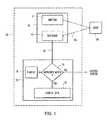
- FIG. 1is a schematic of a preferred embodiment of a biometrically activated device
- FIG. 2is a plan view of one embodiment of the biometric device of the present invention.
- FIG. 3is a cut-away plan view of the biometric device of FIG. 2 ;
- FIG. 4is a plan view of the biometric device of FIG. 2 in an activated state
- FIG. 5is a plan view of the back side of the biometric device of FIG. 2 ;
- FIG. 6Ais a block diagram of a system for securely monitoring an individual
- FIG. 6Bis a block diagram of a portable communications device comprising a biometric sensor
- FIG. 7is a flow diagram of a method for securely monitoring an individual.
- the biometrically activated device of the present inventioncomprises a sensor for sensing or determining certain internal biometric markers of a user in communication with a memory module for storing biometric data or biometric profiles of a user or users corresponding to the internal biometric markers obtained by the sensor.
- the biometric sensorcreates a biometric profile of the user and compares that profile with the stored biometric profile of an authorized user. If the user's profile does not match the profile of an authorized user, the data or information stored within the biometrically activated device is unretrievable.
- the biometrically activated devicebecomes activated for a set duration of time, thereby providing access to the data or information stored within the biometrically activated device or allowing the user to operate an apparatus which the biometrically activated device protects.
- the biometric sensoris configured to determine specific unique internal biometric markers of a user.
- the sensorincludes an emitter and a receiver.
- the emitteremits light or another form of energy which is partially absorbed and partially reflected by a portion of flesh of a user.
- Such light or energymay include, but is not limited to, ultrasonic energy, infra red light, near infra red light, ultra violet light, specific wavelength-visible or nonvisible light, white light, or electrical signals.
- the receivercollects those portions of light or energy that are reflected from the user. Based upon the light or energy reflected, data relating to internal biometric markers may be determined and a biometric profile of the user may be constructed.
- biometric markerswhich may be measured or determined from the biometric sensor include, but are not limited to, bone density, electromagnetic waves, cardiac rhythms, diacrotic notch readings, blood oxygen levels, capillary density, glucose levels, hematocrit levels, or sub-dermal layer analysis.
- Other biometric markerssuch as bio-electric signals, resistance, impedance, capacitance, or other detectable electrical signals emanating from the body may also be detected by the sensor and used or combined with the feedback to the receiver to create a biometric profile of the user.
- the biometric sensormay also include an activation device for activating the biometric sensor so that the biometric sensor is not always activated. Examples of the biometric sensor portion of the biometrically activated device of the present invention are more fully explained in the examples described below.
- the memory module of the biometrically activated deviceis capable of receiving and storing data.
- the memory moduleis also capable of performing functions on the stored or received data to effectuate the creation of a biometric profile for a user.
- a biometric profileis based upon an internal biometric marker or markers of the user.
- Energy signals obtained from the biometric sensormay be converted into electrical signals which in turn may be converted to a biometric profile based upon a mathematical algorithm or transformation.
- the memory modulemay also store the commands or programming which will allow access to the apparatus being protected, or stored data such as phone numbers, account codes, or other information which a user wishes to keep private. Examples of the memory module of the present invention are further explained below.
- the biometrically activated deviceis based upon a user's profile
- the biometrically activated deviceis at least capable of accepting an initial biometric profile corresponding to the desired authorized user.
- the profilemay be determined from the first use of the biometrically activated device or, alternatively, programmed before the first use in accordance with predefined biometric profiles.
- FIG. 1illustrates a schematic of the preferred embodiment of the biometrically activated device of the present invention.
- the device 50includes a biometric sensor 60 and a memory module 70 .
- the biometrically activated deviceis activated by the contact of a user 80 with the biometric sensor 60 of the device 50 .
- the user 80will activate the device 50 by placing a finger on the biometric sensor 60 for a period of time sufficient for the biometric sensor 60 to perform a scan of at least one unique internal biometric marker of the user 80 .
- the device 50may be remotely activated or may be maintained in an activated state.
- Activation of the device 50triggers the emission of energy 65 from an emission device 61 .
- the energy 65is directed towards a user 80 where it is both absorbed and reflected.
- the portion of energy 65 reflected back at the device 50is measured by a receiving device 62 .
- the receiving device 62interprets the amount of energy 65 received and converts the energy into an electrical signal 66 which is communicated to the memory module 70 of the device 50 .
- the energy received by the receiving device 62is converted to an electrical signal 66 by a translator (not shown).
- the memory module 70receives the electrical signal 66 and begins an authentication process of comparing an internal biometric marker, or markers, of the user 80 with the biometric marker, or markers, of the authorized users stored in the memory module 70 .
- the characteristics of the electrical signal 66represent the internal biometric marker, or markers, which the biometric sensor 60 obtains from the user 80 .
- the memory module 70compares the electrical signal 66 to a known biometric profile 76 stored within the memory module 70 . If the electrical signal 66 is identical to the known biometric profile 76 , the biometrically activated device has authenticated the user 80 and allows access to the data 72 stored within the memory module 70 . If the electrical signal 66 , is not authenticated, the biometric device 50 denies access to the data 72 stored within the memory module 70 . Preferably, when access to the data 72 is denied, the biometric device 50 automatically turns off.
- the electrical signal 66may be directly compared to the known biometric profile 76 , the electrical signal 66 may also be transformed within the memory module 70 prior to comparison with the known biometric profile 76 .
- the electrical signal 66may be transformed into a mathematical representation or value based on algorithms programed into the memory module 70 . The algorithms typically represent the necessary transforms needed to interpret the internal biometric marker represented by the electrical signal 66 .
- the mathematical representation or valuewhich represents the biometric profile of the user 80 , is compared to a known biometric profile 76 stored within the memory module 70 . If the mathematical representation or value is authenticated, access to the data 72 stored in the memory module is allowed.
- the data 72 stored within the biometric device 50may be displayed in some manner or used to perform an act on another device.
- the data 72may be displayed on an output device.
- the data 72may trigger the execution of a program within the memory module 70 such that the memory module 70 causes the actuation of a device, such as a door lock, in communication with the memory module. Further examples are described herein.
- FIG. 2illustrates another preferred embodiment of a biometrically activated device: a credit card.
- a biometrically activated deviceis an integral portion of a biometric device 100 , which in this case has the same shape, size and dimensions as a typical credit card. It is understood, however, that the shape, size, and dimensions of the credit card are not limiting to the invention.
- the biometric device 100includes a biometric sensor having a light emitter 112 and a light acceptor 114 .
- the biometric sensor 110may additionally include an activation device 116 as shown in FIG. 2 . Activation of the biometric sensor 110 triggers the light emitter 112 to emit a light 113 .
- An example of a suitable light emitter 112is a light emitting diode (LED). Various types of LED's or alternative light sources may be substituted as the light emitter 112 depending upon the desired wavelength and characteristics of light 113 emanating therefrom.
- the light acceptor 114can be any device capable of absorbing reflected light 113 .
- an individual wishing to use the biometric device 100places a body part, such as a thumb or finger, over the biometric sensor 110 such that light 113 emitted from light emitter 112 is directed toward the body part and is reflected back towards the light acceptor 114 .
- the biometric sensor 110will include an activation switch 116 which activates the biometric sensor 110 when a body part is placed over the biometric sensor 110 , and causes light 113 to be emitted from the light emitter 112 for a fixed duration of time.
- Light 113is partially absorbed and partially reflected by the body part covering the biometric sensor 110 . Reflected light 113 is monitored by the light acceptor 114 .
- a preferred embodiment of the inventionutilizes an infra red LED, which emits sufficient infra red light to penetrate the epidermal layer of skin of a user. A portion of the infra red light is reflected back to the light acceptor 114 while the remainder of the light is absorbed or lost. Based upon the amount of light reflected back to the light acceptor 114 over a period of time, a biometric profile may be established. The portion of the light signal received by the light acceptor 114 is compared to biometric data or a biometric profile stored within the biometric device 100 . If the light signal is identical to the biometric profile stored within the biometric device 100 , the biometric device is activated. Where the light signal does not correspond to the stored biometric data or profile, the biometric device is not activated and the biometric sensor 110 is temporarily turned off.
- FIG. 3depicts a cut-away plan view of the biometric device 100 exposing a memory module 120 in communication with the light acceptor 114 of the biometric sensor 110 .
- the biometric profile of the authorized useris stored within the memory module 120 .
- Other datasuch as account codes, names, addresses, pass codes, or graphics, may also be stored within the memory module 120 .
- the user's biometric profileis compared to the biometric profile stored within memory module 120 . If the user's biometric profile matches that of the biometric profile of the authorized user stored in the memory module 120 , the memory module allows access to at least a portion of the additional data or information stored within the memory module 120 .
- the biometric sensor 110may also include a translator (not shown) which interprets the level of light or energy received by the light acceptor 114 and constructs a biometric profile based upon the data received.
- the translatormay also be an integral portion of the light acceptor 114 wherein the amount of accepted light is transformed into an electric signal.
- the biometric profileis then compared to the biometric data or profile stored within the memory module 120 .
- the memory module 120Upon activation of the biometric device 100 of FIGS. 2 and 3 , the memory module 120 releases the information, such as account information, required to perform an electronic transaction.
- the information stored in the memory module 120maybe released in a number of ways. As illustrated in FIG. 2 , only a portion of the account numbers 150 are embossed on the biometric device 100 . In the instant example, a blank liquid crystal display (LCD) 155 is positioned next to the account numbers 150 .
- the memory module 120activates the LCD 155 and communicates the information necessary to display the remaining account numbers 151 on the LCD 155 , as illustrated in FIG. 4 .
- LCDliquid crystal display
- the memory module 120may repeatedly send account information to a magnetic transmitter 160 on the biometric device, as depicted in FIG. 5 .
- the magnetic transmitter 160 shown in FIG. 5may reside in the same location occupied by the magnetic strip of a credit card, such that the biometric device 100 may be used in the same manner as a credit card upon activation.
- the LCD 155could be replaced with LED's or alternative display devices.
- the magnetic transmitter 160may be replaced with a digital device providing digital signals for a transaction or a light emitter which would release the data or information stored in the memory module 120 by the emission of visible or non-visible light.
- the biometric devicebe self-calibrating.
- the original biometric data or profiles stored in the memory module 120may be calibrated through repetitive use.
- the biometrically activated deviceis used, the biometric profiles obtained are averaged such that a specific number of the most recent successful biometric readings, offset by the original biometric profile, are used to create a more complete biometric profile of the authorized user.
- the biometric device 100can automatically deactivate.
- the memory module 120may be programmed such that, once the user is authenticated and the biometric device is activated, the memory module 120 will display the account numbers 150 on an LCD 155 and/or repeatedly send account information to a magnetic transmitter 160 for a fixed duration of time.
- access to the information stored within the memory module 120may be limited to a specific period of time needed to carry out an electronic transaction.
- This featureadvantageously prevents the unnecessary display of account numbers 150 and electronic copying of information permanently stored in magnetic strips of current credit cards.
- the biometric device 100may only be activated by the authorized user, others are prevented from using the biometric device 100 to perform an invalid transaction.
- the biometric device 100may further include a power source 170 to supply the necessary energy for the operation of the biometric device 100 , as depicted in FIG. 3 .
- the power sourcemay be in the form of a battery, a capacitor, a fuel cell, or alternative energy-producing or storage mechanism. Likewise, the power source may be rechargeable. Examples of alternative power sources include photocells, piezo electric generators, static generators, heat absorbers and other power generation mechanisms.
- biometrically activated device of the present inventionis not limited to use in credit cards.
- a security badgecould employ the present invention, allowing only the authorized user the ability to use the security badge.
- drivers licenses or other identification cards using the biometrically activated devicewould guarantee that only the authorized user could properly operate the biometric device.
- a drivers licensecould employ a biometrically activated device. The data on a drivers license, or the picture of the individual owning the drivers license, stored within the memory module could be displayed upon the proper authentication of the user of the license.
- the biometrically activated device of the instant inventioncould additionally be utilized in cell phones. As cell phones become more advanced and more information is stored within the cell phone, it is desirable to provide a means with which to secure the data stored therein. As cell phones and Personal Data Assistants (PDA) are integrated and combined, the need for security will become even more imperative. In order to protect such devices and restrict access to the authorized users of the device, a cell phone or PDA (or combination thereof) could be equipped with the biometrically activated device of the present invention. Thus, the cell phone or PDA could only be activated by the owner or other authorized user of the device.
- PDAPersonal Data Assistants
- the memory module 120 of the devicecould be programmed to actuate a mechanical device, such as a door lock.
- the necessary control codes, or required programming in the biometrically activated deviceallow a user to perform mechanical functions based upon the proper authentication of the user.
- the present inventionis not limited in use, but rather may be employed in any environment where it is necessary or desirous to provide an inexpensive and portable security measure which restricts use of a device to individuals having certain, programmed biometric profiles to access data or information stored within the device or initiate a process.
- Embodiments of the present inventioncan include, but are not limited to, card-based products such as credit cards, smart cards, debit cards, ATM access cards, facilities access cards, security cards, identification cards or other card-based products requiring secure use or activation. Also included, for example, are activation mechanisms for products such as computers, microcomputers, PDA's (personal data assistants), cell phones, secure access systems, secure entry systems, software access mechanisms, PIN number replacement, firearm locks, transaction activation, or voting mechanisms.
- the present inventioncan additionally be utilized as a security feature in drivers licenses, passports, theme park passes, safebox access and the like. Further examples include the combination of the present invention with an interactive display screen or computer device to protect computers or information transmitted over the internet.
- the biometric sensor coupled to a communications device as described abovemay be used as part of a secure monitoring system.
- the monitoring systemmay leverage the biometric sensor disclosed herein to obtain measurements of various biological characteristics of an individual, derive from the measurements one or more biometric markers, and transmit the biometric markers and/or measurements to a monitoring service.
- the monitoring servicemay use the information to determine the identity of the individual, authenticate the information, and perform a monitoring function using the information.
- the monitoring functionmay determine what, if any, actions should be taken responsive to a particular set of measurements received from an individual.
- the monitoring functionmay provide the user and/or heath care professionals associated with the individual, an indication of the current health state of the individual.
- FIG. 6Ais a block diagram of a system for securely monitoring an individual using a biometric sensor coupled to a portable communications device.
- the portable communications device 602includes a biometric sensor 604 , which may be configured to measure one or more biological characteristics of an individual 601 .
- the biometric sensor 604may be integrally coupled to the portable communications device 602 .
- the biometric sensor 604may be detachable (e.g., may be removable and/or separable from the portable communications device).
- portable communications devicescomprising respective biometric sensors are described above.
- the portable communications device 602may comprise a cellular telephone or smart phone, a personal digital assistant, a portable computer, a media player, or the like.
- the biometric sensor 604may be configured to measure biological characteristics of the individual 601 in various different ways.
- the biometric sensor 604may include an energy emitter and an energy receiver. An example of this type of biometric sensor 604 is described above in conjunction with FIG. 1 .
- the energy emittermay be configured to emit electrical, electro-optical (EO) radiation, or other types of energy radiation into the individual 601 .
- the emittermay be configured to emit infrared and/or near-infrared light energy into the individual 601 .
- the energy emittermay emit energy configured to penetrate the epidermis of the individual 601 to measure an internal, sub-epidermal characteristic of the individual 601 , such as a non-volitional process occurring within the user (e.g., a heartbeat, nervous system response, etc.), a sub-epidermal structure within the user (e.g., a histological characteristic, such as a blood vessel pattern, a skeletal structure, tissue structure, or the like).
- a non-volitional process occurring within the usere.g., a heartbeat, nervous system response, etc.
- a sub-epidermal structure within the usere.g., a histological characteristic, such as a blood vessel pattern, a skeletal structure, tissue structure, or the like.
- the energy emittermay be configured to emit energy of different types (e.g., at various different wavelengths) and/or at various different orientations and/or angles relative to the individual 601 .
- the biometric sensor 604may incorporate multiple energy emitters, each configured to emit a respective type of energy at a particular location and/or orientation relative to the individual 601 .
- the biometric sensor 604may include one or more energy receivers configured to detect an energy signal responsive to the emitted energy.
- the receiversmay be configured to detect various different types of EO radiation including, EO radiation, electrical energy, or the like.
- the biometric sensor 604may leverage existing component of the portable communications device 602 .
- the energy receivermay be implemented in conjunction with other features of the device, such as a camera.
- the portable communications device 602(which may include a cellular telephone, smart phone, a PDA, or the like) may include a camera or other imaging device.
- the cameramay include an EO capture component, such as a charge-coupled device (CCD) or other EO detector.
- CCDcharge-coupled device
- the biometric sensor 604may leverage the CCD (or other EO sensor) to detect EO radiation responsive to emission by the EO emitter.
- the CCDmay be adapted to detect EO radiation of the proper wavelength, which may require a modification of the CCD from that of a typical camera.
- the CCDmay be used to augment another energy sensor (e.g., the camera CCD may be configured to capture EO radiation in the visible spectrum and the biometric sensor 604 may include another sensor configured to capture other types and/or wavelengths of EO radiation).
- the energy emitter of the biometric sensor 604may leverage components of the portable communications device 602 .
- the portable communications device 602may include a flash for the camera, illumination LED to illuminate controls of the device 602 , or the like. These various emitters may be leveraged to emit EO radiation (or other radiation types) into the individual 601 .
- the communications device 602may include an energy storage device, such as a battery, and may include one or more electrical contacts or conductive surfaces.
- the energy storage devicemay be used to power the biometric sensor 604 (e.g., to allow energy to be emitted into and/or received from or through the individual 601 ).
- the electrical contactsmay be used to emit electrical energy into the individual 601 (e.g., apply a voltage differential to a portion of the individual's body, cause a current to flow though the individual's tissue, or the like).
- the biometric sensor 604may be and/or comprise a passive sensor.
- a passive sensormay be configured to measure internal, sub-epidermal characteristics without emitting energy into the individual 601 .
- the biometric sensor 604may include an electrical contact configured to measure a current and/or voltage differential within the individual 601 .
- the passive sensormay be configured to detect a magnetic field indicative of electrical activity occurring within the individual 601 .
- the electrical signalmay be indicative of a heartbeat waveform of the individual 601 (e.g., an electrocardiogram), may be related to the individual's nervous system, may be related to the individual's sensory system, may be a neurological signal, or the like.
- the device 602may include a processing module 607 , which may be communicatively coupled to the biometric sensor 604 .
- the processing module 607may be communicatively coupled to a memory module 608 , which may comprise computer-readable instructions.
- the memory module 608may include a disk, memory (e.g., flash memory), or any other storage medium known in the art.
- the processing module 607 and/or the memory module 608may be shared resources that are used by the portable communications device 602 to provide communications and other services, such as, media services (e.g., music player, video viewer, etc.), provide contact information, store photos, provide various applications (e.g., word processing, email, etc.), and the like.
- the processing module 607 and/or the memory module 608may be dedicated for the use with the biometric sensor 604 .
- the biometric sensor 604may include one or more EO emitters 605 and one or more EO receivers 606 , which, as discussed above, may be configured to emit EO radiation into the individual 601 and detect EO signal(s) responsive thereto.
- multiple EO emitters 605 and/or EO receivers 606may be used provide for stereo imaging of the individual 601 .
- different EO emitters 605 and/or EO receivers 606may be used to emit different types of EO radiation into the individual 601 (e.g., EO radiation of different wavelengths, intensities, etc.) and/or from different locations and/or orientations for use with different types of individuals 601 .
- the biometric sensor 604may include one or more passive sensors (not shown).
- the biometric sensor 604may be configured to transmit to the processing module 607 , signals representative of the energy signals received by the EO receiver(s) 606 (e.g., using active and/or passive sensors).
- the signalsmay include analog signals, digital signals, or the like.
- the processing module 607may be configured to determine from the signals, measurements of one or more internal, sub-epidermal characteristics of the individual 601 . Determining the measurements may include analyzing the signals (e.g., transforming the signals, combining multiple signals, filtering, converting, or the like) to determine the measurements.
- the biometric sensor 604may obtain signals responsive to various different EO wavelengths, each of which may be adapted to react with different portions of tissue and/or fluid within the individual 601 .
- the wavelengthsmay be selected to detect oxygenated and deoxygenated blood cells within the individual 601 .
- the processing module 607may combine signals corresponding to energy received responsive to the different wavelengths to measure a blood flow, oxygen level, or other characteristics of the individual 601 .
- the processing module 607may be configured to combine signals representative of energy signals received responsive to energy emissions obtained at various locations and/or angles relative to the individual 601 .
- the various signalsmay be combined to create a model (e.g., a 2D or 3D model) of a blood vessel pattern within the individual 601 .
- the processing module 607may derive one or more biometric markers from one or more of the measurements as discussed above.
- One of the biometric markersmay be derived from a measurement of an internal, sub-epidermal characteristic of the individual 601 , such as a non-volitional process occurring within the individual 601 , internal, sub-epidermal structure within the individual 601 , or the like. Examples, of various biometric markers related to various measurements are described above.
- the processing module 607may determine a biometric marker that is substantially unique to the individual 601 .
- the processing module 607may additionally determine one or more biometric markers that are not as unique to the individual 601 (e.g., do not uniquely identify the individual 601 , but may distinguish the individual 601 from some portion of the population).
- a biometric markermay merely be indicative that the user is a living human (e.g., as opposed to an automatic replay device, a non-human spoofing device, non-living human tissue, or the like), the marker may distinguish the individual 601 from fifty-percent of the population, from eighty-percent of the population, and so on.
- One or more of the biometric markersmay be used to verify that a unique biometric marker was obtained from a living human and/or may be used with (e.g., layered with) other biometric markers.
- the processing module 607may be configured to activate the portable communications device 602 .
- Activating the portable communications device 602may include activating a communications interface 622 , which may be communicatively coupled to the processing module 607 and/or biometric sensor 604 .
- the device 602may be configured to perform a communications function using the communications interface 622 , such as transmitting and/or receiving data on a network, such as communications network 620 of FIG. 6A .
- 6Amay comprise any communication network (or combination of networks) known in the art including, but not limited to: a public switched telephone network (PSTN), a data communications network, a TCP/IP network, the Internet, a wireless network, a cellular network, or the like.
- PSTNpublic switched telephone network
- TCP/IPTransmission Control Protocol/Internet Protocol
- the portable communications device 602may be configured to transmit data to a receiver 630 .
- the datamay include the measurements and/or the biometric markers derived therefrom.
- information transmitted from the portable communications device 602 to the receivermay be referred to as a “monitoring packet” 609 .
- a monitoring packet 609may include, but is not limited to: one or more measurements obtained using the biometric sensor 604 , one or more biometric markers derived from the measurements, user-identifying information, and the like.
- the monitoring packet 609 transmitted by the portable communications device 602may include information relating to and/or obtained from the individual 601 .
- the monitoring packet 609may include information, which may be used to identify the individual 601 and/or reduce the search space for the individual 601 by the receiver 630 and/or monitoring service 632 .
- the transmissionmay include the number (or other addressing information) of the portable communications device 602 .
- Transmission over a data network, such as TCP/IPmay include the IP address, media access layer (MAC) address, hardware address, or the like.
- Other communications networks 620may include similar information.
- the information transmitted over the network 620may be protected by a transport layer security mechanism, such as encryption (e.g., using secure sockets layer (SSL) or another standard), authentication (e.g., mutually authenticated SSL), or the like.
- the transport layer securitymay prevent the information transmitted by the device 602 from being acquired by an unauthorized receiver (e.g., in a man-in-the middle attack).
- the receiver 630may receive the monitoring packet 609 transmitted by the portable communications device 602 .
- the receiver 630may include and/or be communicatively coupled to a monitoring service 632 , which may be configured to monitor one or more individuals, such as the individual 601 .
- the receiver 630 and/or the monitoring service 632may comprise one or more computing devices (server computers) comprised of one or more processors, memory units, processing units, input/output devices, displays, communications interfaces, and the like.
- the receiver 630may include and/or be communicatively coupled to a data store 634 , comprising information on various individuals.
- a data store 634comprising information on various individuals.
- information about an individual that is maintained by the receiver 630 and/or the monitoring service 632 on the data store 634may be referred to as an individual profile 636 .
- an individual profile 636may refer to a data structure comprising information about an individual 601 .
- the data structure embodying an individual profile 636may be stored on the data store 634 , which may include a computer-readable storage medium.
- an individual profile 636may include, but is not limited to: a biometric profile of the individual 601 , the biometric profile comprising one or more biometric markers and/or measurements of internal, sub-epidermal characteristics of the individual 601 , measurements received from an individual 601 over a particular time period, monitoring instructions for the individual 601 (e.g., rules, triggers, thresholds, and the like), indentifying information, and the like.
- the monitoring service 632 and/or the data store 634may include a security layer 633 (discussed below), which may be configured to enforce access control or other security measures to protect the individual profiles 636 .
- the data store 634may be implemented using any data storage and/or data management technique known in the art including, but not limited to: a relational database, an XML database, a directory, a file system, or the like. Accordingly, the data store 634 may include one or more fixed disks, non-volatile memory (Flash memory), volatile memory, optical storage, tape storage, and the like.
- an individual profile 636may include information relating to monitoring of an individual 601 , and, as such may include baseline biological measurements of various characteristics of the individual 601 , including, but not limited to: a baseline heartbeat waveform, hemodynamic waveform, blood pressure, pulse rate, blood oxygen level, glucose level, tissue features, and the like. These baseline measurements may comprise a biometric profile of the individual 601 , which may be used to monitor the individual 601 .
- the individual profile 636may further include one or more scripts, rules, and/or triggers (discussed below), which may be used to perform a monitoring function on the user.
- the monitoring functionmay be performed to determine an appropriate action (if any) to take in response to a monitoring packet 609 received from the individual 601 .
- Monitoring packets 609 received by the receiver 630may be validated (e.g., using transport layer security mechanisms, such as SSL, mutually authenticated SSL, or the like), and forwarded to the monitoring service 632 .
- the forwardingmay comprise scanning the monitoring packets for viruses, Trojans, or other malicious information or code.
- the monitoring service 632may be protected using various network security features.
- the receiver 630may be placed within a network DMZ and may be separated from the monitoring service 632 by a firewall (not shown) or other network security device.
- the monitoring service 632may be configured to identify the individual 601 associated with the packet 609 , authenticate the identity of the individual 601 and/or the information within the packet 609 , and perform a monitoring function using information within the monitoring packet 609 .
- the receiver 630may identify the information using a biometric marker included with and/or embedded within the monitoring packet 609 .
- a biometric marker determined by the biometric sensor 604may be substantially unique to the individual 601 . Therefore, the biometric marker may be used to identify the individual 601 . Identifying may include comparing the biometric marker in the monitoring packet 609 to information stored in the data store 634 . For example, the biometric marker may be compared to each individual profile 636 within the data store 634 .
- the identity to the individual 601 associated with the monitoring packet 609may be determined by matching an individual profile 636 to the biometric marker therein (e.g., if the biometric marker corresponds to the individual profile 636 , the identity of the sender of the monitoring packet 609 may be determined.)
- the process of identifying the sender of the monitoring packet 609may be hierarchical; for example, the packet 609 may include plural biometric markers.
- One or more of the markersmay not be completely unique to the individual 601 (e.g., may exclude fifty percent of the population).
- the non-substantially unique biometric markersmay provide for relatively fast comparisons (e.g., fast comparisons between the individual profiles 636 and the biometric marker, as opposed to comparisons involving the substantially unique biometric marker(s)). Accordingly, the non-unique biometric marker(s) may be used first to exclude one or more of the individual profiles 636 on the data store 634 . The unique biometric marker may then be applied to the remaining profiles 636 until a match is found.
- the search space for a matching individual profile 636may be reduced using user-identifying information within the monitoring packet 609 .
- the monitoring packet 609may include user-identifying information.
- the informationmay have been provided by the user (e.g., a user name, email address, PIN, or the like), and/or may have been included by the transport-layer (e.g., a hardware address, and IP address, a MAC address, or the like).
- the monitoring service 632may use the user-identifying information to reduce the search space within the data store 634 .
- addressing informationsuch as an IP address, MAC, or the like
- a relationship or association between an individual profile 636 and a device or addressmay be established a priori (e.g., when the individual 601 establishes his/her profile 636 ) and/or may be done on an ad hoc basis (e.g., each time an individual 601 submits a monitoring packet 609 using a new device and/or address, the address may be associated with the individual profile 636 of the individual 601 ).
- the rest of the individual profiles 636may be searched as described above. For example, if a first user borrows a device owned by a second user to transmit a monitoring packet 609 , the user identifying information included with the packet 609 (e.g., IP address, MAC address, etc.) may be associated with the second user (since the device 602 is typically used by the second user). However, the biometric marker in the monitoring packet 609 will not correspond to the individual profile 636 of the second user. Upon determining that the user-identifying information did not provide a match, the monitoring service 632 and/or security layer 633 may search the rest of the individual profiles 636 (or a subset thereof) to identify the individual profile 636 of the first user.
- the user identifying information included with the packet 609e.g., IP address, MAC address, etc.
- the monitoring service 632 and/or security layer 633may search the rest of the individual profiles 636 (or a subset thereof) to identify the individual profile 636 of the first user.
- the monitoring service 632 and/or security layer 633may be configured to authenticate the information within the monitoring packet 609 .
- the packet 609may be authenticated in part by the transport layer used to transmit the packet 609 (e.g., by the SSL or mutually authenticated SSL connection).
- the monitoring packet 609may include one or more biometric markers. The biometric markers may be compared to information in the identified individual profile 636 .
- the individual profile 636may include one or more biometric markers corresponding to the biometric markers transmitted in the packet 609 .
- the markersmay be compared and, if the markers correspond to one another (e.g., match within a particular tolerance or threshold), the markers may be identified as being produced by the individual 601 (e.g., may be authenticated).
- the individual profile and/or packet 609may include one or more baseline measurements and/or a biometric profile from which a biometric marker may be derived. The derived biometric markers may be compared for a match.
- the authenticationmay include a challenge/response interaction. Responsive to identifying the individual profile 636 associated with the monitoring packet 609 , the monitoring service 632 and/or security layer 633 may transmit a challenge message 611 to the portable communications device 602 .
- the challenge 611may require that the individual 601 provide a particular authentication credential (e.g., a digital signature), a password, or the like.
- the challenge 611may request a particular biometric marker or biological measurement. For example, the challenge 611 may request a hemodynamic waveform of the user, a blood vessel pattern of the user, or the like.
- the monitoring service 632 and/or security layer 633may select the biometric marker or measurement for the challenge 611 from a set of measurements that the biometric sensor 604 is capable of acquiring. The selection may be random or may follow a predetermined pattern. The selection of the particular biometric marker and/or measurement may prevent a replay or similar attack.
- the processing module607 in FIG. 6B ) may be configured to obtain the requested biometric marker and/or measurement using the biometric sensor 604 . As shown in FIG. 6A , a response 613 to the challenge may then be transmitted to the receiver 630 via the network 620 .
- the monitoring service 632 and/or security layer 633may validate the response 613 to the challenge 611 and, if the response 613 is validated, may authenticate the individual 601 .
- the monitoring service 632 and/or security layer 633may authenticate the monitoring packet 609 and/or the identity of the individual 601 on the basis of the biometric marker(s) within the monitoring packet 609 .
- the monitoring service 632 and/or security layer 633may determine whether to perform a challenge/response procedure according to the contents of the monitoring packet 609 . For example, if the monitoring packet 609 includes a “weak” biometric marker (not particular unique to the individual 601 ), a challenge/response may be issued.
- the monitoring packet 609is received from a device, location, and/or address that has not been used by the individual 601 in the past (e.g., the individual 601 is using a new communications device 602 for the monitoring), a challenge/response procedure may be followed. However, if several strong biometric markers and/or measurements are provided in the monitoring packet 609 , no challenge 611 may be issued.
- the monitoring service 632may perform a monitoring function.
- the monitoring functionmay be defined in one or more scripts, rules, and/or triggers.
- a monitoring scriptmay compare the one or more measurements within the monitoring packet 609 to one or more baseline measurements of the individual 601 , to one or more thresholds, or the like. The results of the comparisons may be evaluated by one or more rules and/or triggers.
- a rulemay specify a particular action in response to a particular measurement and/or deviation between a measurement and an established baseline of the individual 601 . For example, if a hemodynamic waveform measurement in the packet 609 exceeds a particular threshold (e.g., a systolic and/or diastolic pressure threshold) a first action may be triggered by the monitoring service 632 . If a heartbeat waveform measurement in the monitoring packet 609 shows a divergence from a baseline measurement (e.g., exhibits an abnormal rhythm or the like) a second action may be triggered. In another example, if the blood oxygen level of the individual 601 shows a divergence from the established baseline of the individual 601 , a third action may be triggered, and so on.
- a particular thresholde.g., a systolic and/or diastolic pressure threshold
- the triggers associated with the individual profile 636may determine the nature of the actions taken by the monitoring service 636 in response to the rules discussed above.
- the triggersmay define various different thresholds, each of which may result in a different action taken by the monitoring service 632 . For example, if the divergence between the hemodynamic waveform exceeds a threshold by a small mount, the trigger may determine a first action, if the threshold is exceeded by a larger amount a second action may be taken, and so on. For instance, a small divergence in a blood pressure measurement may trigger an alert to the individual 601 to take a particular action (e.g., reduce activity level, control stress, etc.).
- a particular actione.g., reduce activity level, control stress, etc.
- the alertmay be transmitted from the monitoring service to the individual 601 via the portable communications device 602 or some other device or address (e.g., email address, SMS message, voice message, or the like).
- the alertmay include an audible alarm, vibration, or other alerting mechanism provided by the mobile communications device 602 (e.g., a ringtone or the like).
- heath care providers responsible for the care and/or monitoring of the individual 601may be notified (e.g., a doctor or other health care provider 641 ), a health care entity 640 (discussed below), or the like). If a more significant divergence is observed, a different response from the monitoring service 632 may be triggered.
- the individual 601may be alerted to seek medical attention immediately (e.g., via the portable communications device 602 or the like), medical response personnel may be dispatched to the individual 601 (e.g., in an ambulance response or less urgent method if appropriate).
- a rule and/or triggermay include multiple measurements, such as a combination of pulse rate and pressure.
- a rule or triggermay be activated responsive to changes in both measurements (e.g., a divergence in both measurements may indicate a more serious condition than a change in a single measurement).
- a combination of changesmay be capable of detecting more subtle changes within the measurements. For instance, a serious condition may be detected by small changes in a plurality of measurements as opposed to waiting for a more significant change in a single measurement.
- a rule and/or triggermay specify a change to the monitoring of the individual 601 .
- a triggermay indicate that a different set of measurements are required for proper monitoring (e.g., may require a hemodynamic waveform).
- a triggermay transmit a reconfiguration message to the portable communications device 602 to configure the device to include the additional measurement(s) in subsequent monitoring packets 609 .
- a triggermay indicate that one or more measurements are redundant or unnecessary and a corresponding reconfiguration message may be transmitted.
- an individual 601may provide monitoring packets 609 at a particular interval.
- the individual 601may be reminded to provide the measurements by the portable communications device 602 (e.g., via a prompt issued by the device via a ring, message, or the like).
- the promptmay be provided by the monitoring service 632 by way of a reminder message.
- a trigger or rule associated with the individual profile 636may modify the frequency of the monitoring according to the measurements provided by the individual 601 . For instance, if a trigger or rule indicates a slight divergence from a particular baseline or threshold, the monitoring frequency may be increased. Alternatively, if the user has provided steady measurements for a particular time period, the monitoring frequency may be decreased, and so on.
- the monitoring service 632may determine that an additional measurement is required right away. For example, a first measurement may be indicative of a particular condition or health state. The monitoring service 632 may determine (according to a particular trigger or rule) that in order to verify the condition or heath state, one or more additional measurements are required. Accordingly, the monitoring service 632 may issue a request to the portable communications device 602 to cause the device to prompt the individual 601 to provide the requested measurement.
- monitoring service 632is described as using a particular monitoring function comprising scripts, rules, and/or triggers, the monitoring service 632 described herein is not limited in this regard.
- the monitoring service 632could be adapted to use any monitoring technique and/or methodology known in the art.
- the monitoring service 632may be communicatively coupled to a health care entity 640 .
- the entity 640may represent a doctor, group of doctors, a health maintenance organization, healthcare cooperative, a hospital, a clinic, or the like.
- the monitoring service 632may provide the health care entity 640 with information regarding individuals in the care of the health care entity 640 . Accordingly, personnel and/or automated systems within the entity 640 may have access to one or more portions of one or more individual profiles 636 available on the data store 634 (e.g., measurements obtained from the individual 601 via the device 602 ).
- the informationmay include, but is not limited to: a health state of the individual 601 (as determined by the monitoring service 632 ), the scripts, rules, and/or triggers of the individual 601 , historical measurement readings, or the like. Access to the information in the individual profile 636 may be controlled by the security layer 633 to conform to one or more sets of regulations (e.g., HIPPA or the like).
- the health care entity 640 and/or authorized personnel of the entitymay be allowed to modify the individual profile 636 of the individual 601 .
- the modificationsmay include changing the nature of the monitoring performed by the monitoring service 632 , changing the types of measurements requested from the individual 601 , and the like.
- the health care entity 640(or health care provider 641 ) may define the types of measurements to be obtained from the individual 601 , the frequency at which the monitoring should be performed, and the like.
- the health care entity 640may modify the script, rules, and/or triggers associated with the individual 601 .
- the health care entity 640may define conditions, which may cause the monitoring service 632 to contact or alert the entity 640 (e.g., define the thresholds, etc. evaluated by the monitoring service 632 ). In other embodiments, the monitoring service 632 itself (or personnel of the monitoring service 632 may perform these functions).
- the individual 601may have access to portions of his/her individual profile 636 .
- the accessmay be provided via the network 620 .
- the monitoring service 632 and/or the receiver 630may include and/or be communicatively coupled to a web server or other server computing device (e.g., the receiver 630 may include a web server and/or be communicatively coupled to a separate web server computing device (not shown)).
- the individual 601may access the web server using a communications device (e.g., personal computer, cellular phone, PDA, or the like).
- the individual 601may authenticate his/her identity to the web server (e.g., using a biometric marker as described above or using other means for authentication, such as a password, certificate, credential, or the like).
- the web servermay provide an interface configured to display portions of the individual profile 636 .
- the individual 601may access the measurements obtained via the portable communications device 602 , access any alerts and/or triggers that have been detected by the monitoring service 632 , and so on.
- information derived from the measurementssuch as health state, calories burned, or the like, may be displayed.
- the individual 601may be allowed to modify his/her individual profile 636 through the interface. For instance, the individual 601 may change frequency he/she is reminded to provide monitoring information, change the types of measurements obtained by the biometric sensor 604 , and so on.
- FIG. 7is a flow diagram of one embodiment of a method for securely monitoring an individual using a portable communications device comprising a biometric sensor.
- the method 700may comprise one or more machine executable instructions stored on a computer-readable storage medium.
- the instructionsmay be configured to cause a machine, such as a computing device, to perform the method 700 .
- the instructionsmay be embodied as one or more distinct software modules on the storage medium.
- One or more of the instructions and/or steps of method 700may interact with one or more hardware components, such as computer-readable storage media, communications interfaces, or the like. Accordingly, one or more of the steps of method 700 may be tied to particular machine components.
- a biometric sensor coupled to a communication devicemay obtain one or more biological measurements of an individual.
- One or more of the measurementsmay correspond to internal, sub-epidermal characteristics of the individual, such as non-volitional processes occurring within the individual, sub-epidermal structure within the individual, or the like.
- the biometric sensormay be configured to obtain measurements from the individual each time the individual utilizes the communication device.
- the measurementsmay be acquired non-invasively while the individual uses the communications device (e.g., makes a call, browses the Internet, authors an email or text message, and so on).
- the measurementsmay be obtained at a particular interval (e.g., every four hours). Accordingly, each time the user access the device, the interval may be evaluated and, if the interval has expired, the measurements may be obtained.
- an alertmay be issued after the internal has expired to prompt the user (e.g., via an audible tone, message, email, or the like) to utilize the communications device to provide the measurements.
- the measurements obtained at step 710may be acquired using an active sensor and/or a passive sensor.
- the sensorsmay be coupled to the communications device, such that as the individual uses the communications device, the sensors may be capable of obtaining the measurements from the user.
- the communications devicemay be adapted to prompt the user to hold the communications device in a certain way to allow the sensors to obtain the measurements.
- a cellular telephonemay include an electrode on the surface of the phone and the individual may be prompted to place the electrode on contact with his/her forehead as the individual uses the device.
- the cellular phonemay include an emitter (e.g., as shown in FIG. 1 ), which may be adapted to receive the finger or other appendage of the individual.
- one or more biometric markersmay be derived from the measurements as described above.
- One or more of the biometric markers derived at step 720may be substantially unique to the individual, whereas other biometric markers may be less unique and/or may be indicative of biological activity of the individual (e.g., indicate that another biometric marker was obtained from a live human).
- one or more of the biometric markers derived at step 720 and/or one or more the measurements obtained at step 710may be transmitted to a receiver using the communications device.
- the transmissionmay be made over any communications network known in the art (e.g., PSTN, TCP/IP, Internet, wireless network, or the like).
- the information transmitted at step 730(the biometric marker(s) and measurement(s)) may be referred to as a “monitoring packet.”
- the transmission of step 730may make use of various transport layer security techniques, such as encryption, authentication, and the like (e.g., SSL, mutually authenticated SSL, etc.).
- the transport level securitymay prevent the monitoring packet from being acquired by an unauthorized receiver (e.g., in a man-in-the middle attack).
- the monitoring packetmay include information that may be used to identify the individual and/or reduce the search space required to identify the individual (in addition to the biometric marker(s) and measurement(s)).
- the informationmay be provided by the individual himself, may be provided by the transport layer, and/or may be embedded within the communications device used to transmit the monitoring packet.
- the user-identifying informationmay include, but is not limited to: a user name, a PIN, an email address, a hardware address, a MAC address, an IP address, and so on. The user-identifying information may be provided by the individual and/or may be automatically included in the monitoring packet without user intervention.
- a monitoring systemmay receive the monitoring packet transmitted at step 730 .
- the monitoring servicemay identify an individual associated with the monitoring packet. The identification may be based upon the biometric marker(s) and/or measurement(s) in the monitoring packet. In addition, and as described above, additional user-identifying information may be used to identify the individual and/or reduce the search space for the individual.
- identifying the individualmay comprise associating the monitoring packet with an individual profile, an individual account, or other data structure associated with the individual (“individual profile” hereafter).
- the individual profilemay include various monitoring information about the user including, but not limited to: one or more pre-established biometric markers of the individual, baseline measurements of the individual, monitoring scripts, rules, and/or triggers, and so on.
- the identification of step 750may result in identifying a particular individual profile associated with the monitoring packet. Therefore, at step 755 , the method 700 may determine whether a single individual has been identified and, if so, the flow may continue to step 760 ; otherwise, if an individual is not identified, the flow may continue to 755 .
- a return messagemay be transmitted to the communications device that transmitted the monitoring packet.
- the messagemay indicate that no individual profile having the provided biometric marker, measurements, and/or user-identifying information could be found.
- the messagemay allow the individual to establish a new individual profile with the monitoring service.
- the messagemay provide relevant links and/or contact information to allow the individual to contact the monitoring service and/or a health care entity (discussed below) for further assistance.
- the flowmay then continue to step 790 .
- the monitoring servicemay authenticate the monitoring packet.
- Authenticating the monitoring packetmay include verifying that the packet was sent by and/or authorized by the individual identified at step 755 .
- the authentication of step 760may include comparing the biometric marker(s) within the monitoring packet to one or more biometric marker(s) and/or measurements within the individual profile identified at step 755 . If the biometric marker(s) correspond to the identified individual profile, the monitoring packet may be authenticated.
- the authentication of step 760may include a challenge/response.
- the monitoring servicemay issue a challenge to the sender of the monitoring packet (e.g., to the device from which the monitoring packet was received).
- the challengemay request that the individual provide a particular measurement or biometric.
- the monitoring servicemay receive a response to the challenge, which, if validated, may authenticate the monitoring packet.
- the flowmay continue to step 770 ; otherwise, the flow may continue to step 755 .
- a monitoring functionmay be performed.
- the monitoring functionmay be provided by the method 700 or another entity, such as a heath care provider entity, or the like.
- the monitoring function of step 770may comprise performing a script associated with the individual profile as discussed above.
- the scriptmay compare one or more measurements within the monitoring packet to one or more rules, triggers, and the like.
- one or more actionsmay be taken including, but not limited to: transmitting an alert to the individual (e.g., via the communication device or by another mechanism); alerting a health care provider entity; dispatching a medical response to the individual; updating a record (e.g., individual profile) of the individual; transmitting information to the individual (e.g., including a summary of the health state of the individual as indicated by the measurements within the monitoring packet); or the like.
- an individual profile of the individualmay be updated.
- the updatingmay include storing the measurement(s) and/or biometric marker(s) received in the monitoring packet in a computer-readable storage medium (e.g., in an individual profile).
- the measurement(s)may be used to update one or more baseline measurements of the individual.
- the biometric marker(s)may be used to update and/or modify the biometric markers in the profile.
- the individual profilemay reflect gradual changes to the measurements obtained from the individual.
- the original measurement(s) and/or biometric marker(s)may be retained in the profile and/or used for monitoring and/or diagnostic purposes (e.g., to identify trends which may be indicative of a particular health state or condition).
- the flowmay then continue to step 790 .
- the method 700may terminate until another set of measurements is acquired and/or received (at steps 710 and/or 740 ).
- Embodimentsmay include various steps, which may be embodied in machine-executable instructions to be executed by a general-purpose or special-purpose computer (or other electronic device). Alternatively, the steps may be performed by hardware components that include specific logic for performing the steps or by a combination of hardware, software, and/or firmware.
- Embodimentsmay also be provided as a computer program product including a computer-readable medium having stored thereon instructions that may be used to program a computer (or other electronic device) to perform processes described herein.
- the computer-readable mediummay include, but is not limited to, hard drives, floppy diskettes, optical disks, CD-ROMs, DVD-ROMs, ROMs, RAMs, EPROMs, EEPROMs, magnetic or optical cards, solid-state memory devices, or other types of media/machine-readable medium suitable for storing electronic instructions.
- a software module or componentmay include any type of computer instruction or computer executable code located within a memory device and/or transmitted as electronic signals over a system bus or wired or wireless network.
- a software modulemay, for instance, comprise one or more physical or logical blocks of computer instructions, which may be organized as a routine, program, object, module, data structure, etc., that perform one or more tasks or implements particular abstract data types.
- a particular software modulemay comprise disparate instructions stored in different locations of a memory device, which together implement the described functionality of the module.
- a modulemay comprise a single instruction or many instructions, and may be distributed over several different code segments, among different programs, and across several memory devices.
- Some embodimentsmay be practiced in a distributed computing environment where tasks are performed by a remote processing device linked through a communications network.
- software modulesmay be located in local and/or remote memory storage devices.
- data being tied or rendered together in a database recordmay be resident in the same memory device, or across several memory devices, and may be linked together in fields of a record in a database across a network.
Landscapes
- Engineering & Computer Science (AREA)
- Theoretical Computer Science (AREA)
- Computer Security & Cryptography (AREA)
- General Physics & Mathematics (AREA)
- Physics & Mathematics (AREA)
- Computer Hardware Design (AREA)
- General Engineering & Computer Science (AREA)
- Software Systems (AREA)
- Bioethics (AREA)
- General Health & Medical Sciences (AREA)
- Health & Medical Sciences (AREA)
- Multimedia (AREA)
- Databases & Information Systems (AREA)
- Medical Informatics (AREA)
- Computing Systems (AREA)
- Computer Networks & Wireless Communication (AREA)
- Signal Processing (AREA)
- Human Computer Interaction (AREA)
- Automation & Control Theory (AREA)
- Measurement Of The Respiration, Hearing Ability, Form, And Blood Characteristics Of Living Organisms (AREA)
- Measuring And Recording Apparatus For Diagnosis (AREA)
Abstract
Description
Claims (16)
Priority Applications (6)
| Application Number | Priority Date | Filing Date | Title |
|---|---|---|---|
| US12/563,933US8049597B1 (en) | 2000-01-10 | 2009-09-21 | Systems and methods for securely monitoring an individual |
| US13/497,123US9584496B2 (en) | 2009-09-21 | 2010-09-14 | Systems and methods for securely monitoring an individual |
| PCT/US2010/048696WO2011034831A2 (en) | 2009-09-21 | 2010-09-14 | Systems and methods for securely monitoring an individual |
| US15/444,082US10320767B2 (en) | 2009-09-21 | 2017-02-27 | Systems and methods for securely monitoring an individual |
| US16/396,707US10554648B1 (en) | 2009-09-21 | 2019-04-28 | Calibration of a wearable medical device |
| US16/724,217US10911427B1 (en) | 2009-09-21 | 2019-12-21 | Reconfiguration of a wearable medical device |
Applications Claiming Priority (3)
| Application Number | Priority Date | Filing Date | Title |
|---|---|---|---|
| US17546000P | 2000-01-10 | 2000-01-10 | |
| US09/758,836US7796013B2 (en) | 2000-01-10 | 2001-01-10 | Device using histological and physiological biometric marker for authentication and activation |
| US12/563,933US8049597B1 (en) | 2000-01-10 | 2009-09-21 | Systems and methods for securely monitoring an individual |
Related Parent Applications (1)
| Application Number | Title | Priority Date | Filing Date |
|---|---|---|---|
| US09/758,836Continuation-In-PartUS7796013B2 (en) | 2000-01-10 | 2001-01-10 | Device using histological and physiological biometric marker for authentication and activation |
Related Child Applications (3)
| Application Number | Title | Priority Date | Filing Date |
|---|---|---|---|
| US13/497,123ContinuationUS9584496B2 (en) | 2009-09-21 | 2010-09-14 | Systems and methods for securely monitoring an individual |
| PCT/US2010/048696ContinuationWO2011034831A2 (en) | 2009-09-21 | 2010-09-14 | Systems and methods for securely monitoring an individual |
| US201213497123AContinuation | 2009-09-21 | 2012-09-05 |
Publications (1)
| Publication Number | Publication Date |
|---|---|
| US8049597B1true US8049597B1 (en) | 2011-11-01 |
Family
ID=43759245
Family Applications (5)
| Application Number | Title | Priority Date | Filing Date |
|---|---|---|---|
| US12/563,933Expired - LifetimeUS8049597B1 (en) | 2000-01-10 | 2009-09-21 | Systems and methods for securely monitoring an individual |
| US13/497,123Active2032-09-30US9584496B2 (en) | 2009-09-21 | 2010-09-14 | Systems and methods for securely monitoring an individual |
| US15/444,082Active - ReinstatedUS10320767B2 (en) | 2009-09-21 | 2017-02-27 | Systems and methods for securely monitoring an individual |
| US16/396,707ActiveUS10554648B1 (en) | 2009-09-21 | 2019-04-28 | Calibration of a wearable medical device |
| US16/724,217ActiveUS10911427B1 (en) | 2009-09-21 | 2019-12-21 | Reconfiguration of a wearable medical device |
Family Applications After (4)
| Application Number | Title | Priority Date | Filing Date |
|---|---|---|---|
| US13/497,123Active2032-09-30US9584496B2 (en) | 2009-09-21 | 2010-09-14 | Systems and methods for securely monitoring an individual |
| US15/444,082Active - ReinstatedUS10320767B2 (en) | 2009-09-21 | 2017-02-27 | Systems and methods for securely monitoring an individual |
| US16/396,707ActiveUS10554648B1 (en) | 2009-09-21 | 2019-04-28 | Calibration of a wearable medical device |
| US16/724,217ActiveUS10911427B1 (en) | 2009-09-21 | 2019-12-21 | Reconfiguration of a wearable medical device |
Country Status (2)
| Country | Link |
|---|---|
| US (5) | US8049597B1 (en) |
| WO (1) | WO2011034831A2 (en) |
Cited By (28)
| Publication number | Priority date | Publication date | Assignee | Title |
|---|---|---|---|---|
| US20120019643A1 (en)* | 2010-07-26 | 2012-01-26 | Atlas Advisory Partners, Llc | Passive Demographic Measurement Apparatus |
| US20130057385A1 (en)* | 2009-09-21 | 2013-03-07 | Ensign Holdings. LLC | Systems and methods for securely monitoring an individual |
| US20130104050A1 (en)* | 2010-11-18 | 2013-04-25 | Huawei Device Co., Ltd. | Method and terminal for changing user operation interface |
| US20150095720A1 (en)* | 2010-03-25 | 2015-04-02 | Oracle International Corporation | Proactive and adaptive cloud monitoring |
| US20150184964A1 (en)* | 2013-02-06 | 2015-07-02 | Karl F. Milde, Jr. | Secure smartphone-operated gun lock with means for overriding release of the lock |
| US20150184963A1 (en)* | 2013-02-06 | 2015-07-02 | Karl F. Milde, Jr. | Secure smartphone-operated gun lock with means for overriding release of the lock |
| US20150197977A1 (en)* | 2014-01-16 | 2015-07-16 | Wincor Nixdorf International Gmbh | Device for handling notes of value comprising an intermediate module adaptable to the thickness of the safe wall |
| US20150365825A1 (en)* | 2014-06-12 | 2015-12-17 | Sony Corporation | Electronic Equipment and Method of Authenticating a User |
| US9310147B2 (en)* | 2013-02-06 | 2016-04-12 | Karl F. Milde, Jr. | Secure smartphone-operated gun trigger lock |
| US20170024553A1 (en)* | 2015-07-21 | 2017-01-26 | Synaptics Incorporated | Temporary secure access via input object remaining in place |
| USD791772S1 (en)* | 2015-05-20 | 2017-07-11 | Chaya Coleena Hendrick | Smart card with a fingerprint sensor |
| US9824287B2 (en)* | 2015-09-29 | 2017-11-21 | Huami Inc. | Method, apparatus and system for biometric identification |
| US10139179B2 (en)* | 2016-12-13 | 2018-11-27 | Gentex Corporation | Biometric identification system for gun |
| US20190196772A1 (en)* | 2010-05-28 | 2019-06-27 | Sony Corporation | Information processing apparatus, information processing system, and program |
| US10340034B2 (en) | 2011-12-30 | 2019-07-02 | Elwha Llc | Evidence-based healthcare information management protocols |
| US10368744B1 (en)* | 2015-02-17 | 2019-08-06 | Halo Wearables, Llc | Baselining user profiles from portable device information |
| US10402927B2 (en) | 2011-12-30 | 2019-09-03 | Elwha Llc | Evidence-based healthcare information management protocols |
| US10467548B2 (en) | 2015-09-29 | 2019-11-05 | Huami Inc. | Method, apparatus and system for biometric identification |
| US10475142B2 (en) | 2011-12-30 | 2019-11-12 | Elwha Llc | Evidence-based healthcare information management protocols |
| US10503268B2 (en)* | 2015-08-07 | 2019-12-10 | Fitbit, Inc. | User identification via motion and heartbeat waveform data |
| US10528913B2 (en) | 2011-12-30 | 2020-01-07 | Elwha Llc | Evidence-based healthcare information management protocols |
| US10552581B2 (en) | 2011-12-30 | 2020-02-04 | Elwha Llc | Evidence-based healthcare information management protocols |
| US10559380B2 (en) | 2011-12-30 | 2020-02-11 | Elwha Llc | Evidence-based healthcare information management protocols |
| US10679309B2 (en) | 2011-12-30 | 2020-06-09 | Elwha Llc | Evidence-based healthcare information management protocols |
| US10806398B2 (en) | 2015-02-17 | 2020-10-20 | Halo Wearables, Llc | Power management for wearable devices |
| US11087018B2 (en)* | 2016-04-28 | 2021-08-10 | Nokia Technologies Oy | Apparatus, method and computer program for scrambling an identification signal using quantum dot-graphene field effect transistors |
| US20230099358A1 (en)* | 2007-10-22 | 2023-03-30 | CPC Patent Technologies Pty Ltd. | Transmitter for transmitting a secure access signal |
| US20230410637A1 (en)* | 2020-11-05 | 2023-12-21 | Maxell, Ltd. | Linked notification system, portable communication device, and linked notification method for portable communication device |
Families Citing this family (50)
| Publication number | Priority date | Publication date | Assignee | Title |
|---|---|---|---|---|
| US9198608B2 (en) | 2005-04-28 | 2015-12-01 | Proteus Digital Health, Inc. | Communication system incorporated in a container |
| US8730031B2 (en) | 2005-04-28 | 2014-05-20 | Proteus Digital Health, Inc. | Communication system using an implantable device |
| JP2009544338A (en) | 2006-05-02 | 2009-12-17 | プロテウス バイオメディカル インコーポレイテッド | Treatment regimen customized to the patient |
| SG175681A1 (en) | 2006-10-25 | 2011-11-28 | Proteus Biomedical Inc | Controlled activation ingestible identifier |
| US8718193B2 (en) | 2006-11-20 | 2014-05-06 | Proteus Digital Health, Inc. | Active signal processing personal health signal receivers |
| CN101686800A (en) | 2007-02-01 | 2010-03-31 | 普罗秋斯生物医学公司 | Ingestible Event Marker System |
| US8956288B2 (en) | 2007-02-14 | 2015-02-17 | Proteus Digital Health, Inc. | In-body power source having high surface area electrode |
| EP2124725A1 (en) | 2007-03-09 | 2009-12-02 | Proteus Biomedical, Inc. | In-body device having a multi-directional transmitter |
| US8115618B2 (en) | 2007-05-24 | 2012-02-14 | Proteus Biomedical, Inc. | RFID antenna for in-body device |
| DK2192946T3 (en) | 2007-09-25 | 2022-11-21 | Otsuka Pharma Co Ltd | In-body device with virtual dipole signal amplification |
| CN104376659B (en) | 2008-03-05 | 2019-10-25 | 普罗透斯数字保健公司 | The ingestible event flag of multi-modal communications and system, and the method using it |
| AU2009268827B2 (en) | 2008-07-08 | 2013-10-24 | Proteus Digital Health, Inc. | Ingestible event marker data framework |
| US9659423B2 (en) | 2008-12-15 | 2017-05-23 | Proteus Digital Health, Inc. | Personal authentication apparatus system and method |
| US9439566B2 (en) | 2008-12-15 | 2016-09-13 | Proteus Digital Health, Inc. | Re-wearable wireless device |
| KR20110103446A (en) | 2009-01-06 | 2011-09-20 | 프로테우스 바이오메디컬, 인코포레이티드 | Intake-Related Biofeedback and Individualized Medical Treatment Methods and Systems |
| TWI517050B (en) | 2009-11-04 | 2016-01-11 | 普羅托斯數位健康公司 | System for supply chain management |
| BR112012019212A2 (en) | 2010-02-01 | 2017-06-13 | Proteus Digital Health Inc | data collection system |
| TWI557672B (en) | 2010-05-19 | 2016-11-11 | 波提亞斯數位康健公司 | Computer system and computer-implemented method to track medication from manufacturer to a patient, apparatus and method for confirming delivery of medication to a patient, patient interface device |
| WO2012125425A2 (en) | 2011-03-11 | 2012-09-20 | Proteus Biomedical, Inc. | Wearable personal body associated device with various physical configurations |
| WO2015112603A1 (en) | 2014-01-21 | 2015-07-30 | Proteus Digital Health, Inc. | Masticable ingestible product and communication system therefor |
| US9756874B2 (en) | 2011-07-11 | 2017-09-12 | Proteus Digital Health, Inc. | Masticable ingestible product and communication system therefor |
| PH12014500174A1 (en) | 2011-07-21 | 2024-02-12 | Proteus Digital Health Inc | Mobile communication device, system, and method |
| KR101160681B1 (en) | 2011-10-19 | 2012-06-28 | 배경덕 | Method, mobile communication terminal and computer-readable recording medium for operating specific function when activaing of mobile communication terminal |
| US9235683B2 (en) | 2011-11-09 | 2016-01-12 | Proteus Digital Health, Inc. | Apparatus, system, and method for managing adherence to a regimen |
| AU2013204744A1 (en) | 2012-07-26 | 2014-02-13 | Peter Cherry | System and Method for Fraud Prevention |
| JP6498177B2 (en) | 2013-03-15 | 2019-04-10 | プロテウス デジタル ヘルス, インコーポレイテッド | Identity authentication system and method |
| US9411925B2 (en) | 2014-04-14 | 2016-08-09 | Lenovo Enterprise Solutions (Singapore) Pte. Ltd. | Simultaneously viewing multi paired schematic and layout windows on printed circuit board (PCB) design software and tools |
| US12039243B2 (en) | 2013-04-15 | 2024-07-16 | Autoconnect Holdings Llc | Access and portability of user profiles stored as templates |
| EP3005281A4 (en) | 2013-06-04 | 2017-06-28 | Proteus Digital Health, Inc. | System, apparatus and methods for data collection and assessing outcomes |
| CA2965941C (en) | 2013-09-20 | 2020-01-28 | Proteus Digital Health, Inc. | Methods, devices and systems for receiving and decoding a signal in the presence of noise using slices and warping |
| WO2015044722A1 (en) | 2013-09-24 | 2015-04-02 | Proteus Digital Health, Inc. | Method and apparatus for use with received electromagnetic signal at a frequency not known exactly in advance |
| US10084880B2 (en) | 2013-11-04 | 2018-09-25 | Proteus Digital Health, Inc. | Social media networking based on physiologic information |
| EP3097515B1 (en)* | 2014-01-21 | 2020-12-09 | Circurre Pty Ltd | Personal identification system and method |
| KR102390874B1 (en) | 2014-10-29 | 2022-04-26 | 삼성전자주식회사 | Glucose measure apparatus and method of measuring glucose thereof |
| US9590986B2 (en)* | 2015-02-04 | 2017-03-07 | Aerendir Mobile Inc. | Local user authentication with neuro and neuro-mechanical fingerprints |
| WO2016168667A1 (en)* | 2015-04-16 | 2016-10-20 | Offender Smartphone Monitoring, LLC | Monitoring process |
| US9433363B1 (en)* | 2015-06-18 | 2016-09-06 | Genetesis Llc | Method and system for high throughput evaluation of functional cardiac electrophysiology |
| CN105550629A (en)* | 2015-08-03 | 2016-05-04 | 宇龙计算机通信科技(深圳)有限公司 | Identity identification method and apparatus |
| GB2544087A (en)* | 2015-11-05 | 2017-05-10 | B-Secur Ltd | Automatic teller machine with biometric authentication |
| KR102447501B1 (en)* | 2015-12-24 | 2022-09-27 | 삼성전자주식회사 | Electronic device for processing biometric information and method for controlling the same |
| KR20210018961A (en) | 2016-07-22 | 2021-02-18 | 프로테우스 디지털 헬스, 인코포레이티드 | Electromagnetic sensing and detection of ingestible event markers |
| US11238992B2 (en)* | 2017-05-16 | 2022-02-01 | Jeffry David Aronson | Configurable concise datasets platform |
| US10943693B2 (en)* | 2017-05-16 | 2021-03-09 | Jeffry David Aronson | Concise datasets platform |
| JP7393947B2 (en) | 2017-05-22 | 2023-12-07 | ジェネテシス エルエルシー | Mechanical identification of anomalies in bioelectromagnetic fields |
| US12262997B2 (en) | 2017-08-09 | 2025-04-01 | Genetesis, Inc. | Biomagnetic detection |
| US11134877B2 (en) | 2017-08-09 | 2021-10-05 | Genetesis, Inc. | Biomagnetic detection |
| US11489958B2 (en)* | 2018-05-02 | 2022-11-01 | Telefonaktiebolaget Lm Ericsson (Publ) | User equipment, method by a user equipment, and network node for generating a grip pattern notification through a user interface based on radio characteristics |
| EP3839899A1 (en)* | 2019-12-19 | 2021-06-23 | GWA Hygiene GmbH | Wearable badge and method for determining a type of an identification card removably held in said badge |
| US11979396B2 (en) | 2021-05-19 | 2024-05-07 | Bank Of America Corporation | Information security system and method for machine-to-machine (M2M) security and validation |
| US12148271B1 (en) | 2023-09-06 | 2024-11-19 | Bank Of America Corporation | System and method for detecting anomalous dispensing devices |
Citations (100)
| Publication number | Priority date | Publication date | Assignee | Title |
|---|---|---|---|---|
| US4109237A (en) | 1977-01-17 | 1978-08-22 | Hill Robert B | Apparatus and method for identifying individuals through their retinal vasculature patterns |
| JPS60126787A (en) | 1983-12-13 | 1985-07-06 | Oki Electric Ind Co Ltd | Card |
| US4537484A (en) | 1984-01-30 | 1985-08-27 | Identix Incorporated | Fingerprint imaging apparatus |
| US4544267A (en) | 1980-11-25 | 1985-10-01 | Fingermatrix, Inc. | Finger identification |
| US4582985A (en) | 1981-03-18 | 1986-04-15 | Loefberg Bo | Data carrier |
| US4614861A (en) | 1984-11-15 | 1986-09-30 | Intellicard International, Inc. | Unitary, self-contained card verification and validation system and method |
| US4699149A (en) | 1984-03-20 | 1987-10-13 | Joseph Rice | Apparatus for the identification of individuals |
| US4728186A (en) | 1985-03-03 | 1988-03-01 | Fujitsu Limited | Uneven-surface data detection apparatus |
| US4784484A (en) | 1985-05-02 | 1988-11-15 | Jydsk Telefon A/S | Method and apparatus for automatic scanning of fingerprints |
| US4846190A (en) | 1983-08-23 | 1989-07-11 | John Erwin R | Electroencephalographic system data display |
| US5036279A (en) | 1987-05-11 | 1991-07-30 | Datalight Limited | Portable NMR and NQR spectrometers |
| US5073950A (en) | 1989-04-13 | 1991-12-17 | Personnel Identification & Entry Access Control, Inc. | Finger profile identification system |
| US5077803A (en) | 1988-09-16 | 1991-12-31 | Fujitsu Limited | Biological detecting system and fingerprint collating system employing same |
| US5088817A (en) | 1988-11-25 | 1992-02-18 | Fujitsu Ltd | Biological object detection apparatus |
| US5103486A (en) | 1990-04-19 | 1992-04-07 | Grippi Victor J | Fingerprint/signature synthesis |
| US5152288A (en) | 1988-09-23 | 1992-10-06 | Siemens Aktiengesellschaft | Apparatus and method for measuring weak, location-dependent and time-dependent magnetic fields |
| US5172698A (en) | 1990-05-24 | 1992-12-22 | Stanko Bruce E | Telephonic pacemaker and single channel EKG monitoring device |
| US5180901A (en) | 1990-05-21 | 1993-01-19 | Kabushiki Kaisha Toshiba | IC card with individual authentication function |
| US5230025A (en) | 1990-08-31 | 1993-07-20 | Digital Biometrics, Inc. | Method and apparatus for capturing skin print images |
| US5311867A (en) | 1993-01-04 | 1994-05-17 | Biomagnetic Technologies, Inc. | Detection and grouping analysis of cardiac cycles |
| US5325862A (en) | 1993-03-26 | 1994-07-05 | The United States Of America As Represented By The Secretary Of The Navy | Method and/or system for personal identification and impairment assessment from brain activity patterns |
| US5335288A (en) | 1992-02-10 | 1994-08-02 | Faulkner Keith W | Apparatus and method for biometric identification |
| US5456256A (en) | 1993-11-04 | 1995-10-10 | Ultra-Scan Corporation | High resolution ultrasonic imaging apparatus and method |
| US5524637A (en)* | 1994-06-29 | 1996-06-11 | Erickson; Jon W. | Interactive system for measuring physiological exertion |
| US5526808A (en) | 1990-10-04 | 1996-06-18 | Microcor, Inc. | Method and apparatus for noninvasively determining hematocrit |
| US5586171A (en) | 1994-07-07 | 1996-12-17 | Bell Atlantic Network Services, Inc. | Selection of a voice recognition data base responsive to video data |
| US5623552A (en) | 1994-01-21 | 1997-04-22 | Cardguard International, Inc. | Self-authenticating identification card with fingerprint identification |
| US5632272A (en)* | 1991-03-07 | 1997-05-27 | Masimo Corporation | Signal processing apparatus |
| US5704352A (en) | 1995-11-22 | 1998-01-06 | Tremblay; Gerald F. | Implantable passive bio-sensor |
| US5719950A (en) | 1994-03-24 | 1998-02-17 | Minnesota Mining And Manufacturing Company | Biometric, personal authentication system |
| US5737439A (en) | 1996-10-29 | 1998-04-07 | Smarttouch, Llc. | Anti-fraud biometric scanner that accurately detects blood flow |
| US5774571A (en) | 1994-08-01 | 1998-06-30 | Edward W. Ellis | Writing instrument with multiple sensors for biometric verification |
| US5771894A (en) | 1995-06-05 | 1998-06-30 | Vanderbilt University | Non invasive identification of intestinal ischemia from measurement of basic electrical rhythm of intestinal smooth muscle electrical activity using a magnetometer |
| US5789733A (en) | 1996-09-20 | 1998-08-04 | Motorola, Inc. | Smart card with contactless optical interface |
| US5793881A (en) | 1995-08-31 | 1998-08-11 | Stiver; John A. | Identification system |
| US5872834A (en) | 1996-09-16 | 1999-02-16 | Dew Engineering And Development Limited | Telephone with biometric sensing device |
| US5935062A (en) | 1995-08-09 | 1999-08-10 | Rio Grande Medical Technologies, Inc. | Diffuse reflectance monitoring apparatus |
| US5982914A (en) | 1997-07-29 | 1999-11-09 | Smarttouch, Inc. | Identification of individuals from association of finger pores and macrofeatures |
| US5987232A (en) | 1995-09-08 | 1999-11-16 | Cadix Inc. | Verification server for use in authentication on networks |
| US6041410A (en)* | 1997-12-22 | 2000-03-21 | Trw Inc. | Personal identification fob |
| JP2000181871A (en) | 1998-12-16 | 2000-06-30 | Internatl Business Mach Corp <Ibm> | Device and method for authentication |
| US6088585A (en) | 1997-05-16 | 2000-07-11 | Authentec, Inc. | Portable telecommunication device including a fingerprint sensor and related methods |
| US6104913A (en) | 1998-03-11 | 2000-08-15 | Bell Atlantic Network Services, Inc. | Personal area network for personal telephone services |
| US6104922A (en) | 1998-03-02 | 2000-08-15 | Motorola, Inc. | User authentication in a communication system utilizing biometric information |
| US6148094A (en) | 1996-09-30 | 2000-11-14 | David J. Kinsella | Pointing device with biometric sensor |
| US6164403A (en) | 1997-12-24 | 2000-12-26 | Stmicroelectronics S.A. | Security system |
| US6171112B1 (en) | 1998-09-18 | 2001-01-09 | Wyngate, Inc. | Methods and apparatus for authenticating informed consent |
| US6182892B1 (en) | 1998-03-25 | 2001-02-06 | Compaq Computer Corporation | Smart card with fingerprint image pass-through |
| US6193153B1 (en) | 1997-04-16 | 2001-02-27 | Francis Lambert | Method and apparatus for non-intrusive biometric capture |
| US6198394B1 (en)* | 1996-12-05 | 2001-03-06 | Stephen C. Jacobsen | System for remote monitoring of personnel |
| US6202151B1 (en) | 1997-05-09 | 2001-03-13 | Gte Service Corporation | System and method for authenticating electronic transactions using biometric certificates |
| US6208264B1 (en) | 1997-05-23 | 2001-03-27 | Automated Identification Service, Inc. | Personal verification in a commercial transaction system |
| US6219639B1 (en) | 1998-04-28 | 2001-04-17 | International Business Machines Corporation | Method and apparatus for recognizing identity of individuals employing synchronized biometrics |
| US6224548B1 (en) | 1998-05-26 | 2001-05-01 | Ineedmd.Com, Inc. | Tele-diagnostic device |
| US6225890B1 (en) | 1998-03-20 | 2001-05-01 | Trimble Navigation Limited | Vehicle use control |
| US6266566B1 (en) | 1999-05-21 | 2001-07-24 | Medtronic, Inc. | Waveform normalization in a medical device |
| US6269348B1 (en) | 1994-11-28 | 2001-07-31 | Veristar Corporation | Tokenless biometric electronic debit and credit transactions |
| US6275806B1 (en) | 1999-08-31 | 2001-08-14 | Andersen Consulting, Llp | System method and article of manufacture for detecting emotion in voice signals by utilizing statistics for voice signal parameters |
| US6289453B1 (en) | 1996-04-08 | 2001-09-11 | Walker Digital, Llc | Method and apparatus for secure measurement certification |
| US20010033220A1 (en) | 2000-02-14 | 2001-10-25 | Stone Robert T. | Security control method and system |
| US20020138768A1 (en) | 2001-03-22 | 2002-09-26 | Murakami Rick V. | Method for biometric authentication through layering biometric traits |
| US6483929B1 (en) | 2000-06-08 | 2002-11-19 | Tarian Llc | Method and apparatus for histological and physiological biometric operation and authentication |
| US20020174347A1 (en) | 2001-05-18 | 2002-11-21 | Imprivata, Inc. | Authentication with variable biometric templates |
| US6496595B1 (en) | 2000-05-19 | 2002-12-17 | Nextgenid, Ltd. | Distributed biometric access control apparatus and method |
| US20020191817A1 (en) | 2001-03-15 | 2002-12-19 | Toshio Sato | Entrance management apparatus and entrance management method |
| US6532298B1 (en)* | 1998-11-25 | 2003-03-11 | Iridian Technologies, Inc. | Portable authentication device and method using iris patterns |
| US6539380B1 (en) | 1999-09-30 | 2003-03-25 | M-Systems Flash Disk Pioneers Ltd. | Device, system and method for data access control |
| US6628809B1 (en) | 1999-10-08 | 2003-09-30 | Lumidigm, Inc. | Apparatus and method for identification of individuals by near-infrared spectrum |
| US20030233557A1 (en) | 2002-06-13 | 2003-12-18 | Zimmerman Thomas Guthrie | Electronic signature verification method and apparatus |
| US6681029B1 (en) | 1993-11-18 | 2004-01-20 | Digimarc Corporation | Decoding steganographic messages embedded in media signals |
| US6695207B1 (en) | 2000-02-04 | 2004-02-24 | Carroll Boyd Norris, Jr. | System for secure, identity authenticated, and immediate financial transactions as well as activation of varied instrumentalities |
| US20040187037A1 (en) | 2003-02-03 | 2004-09-23 | Checco John C. | Method for providing computer-based authentication utilizing biometrics |
| US6816605B2 (en) | 1999-10-08 | 2004-11-09 | Lumidigm, Inc. | Methods and systems for biometric identification of individuals using linear optical spectroscopy |
| US6819219B1 (en)* | 2000-10-13 | 2004-11-16 | International Business Machines Corporation | Method for biometric-based authentication in wireless communication for access control |
| US20040240711A1 (en) | 2003-05-27 | 2004-12-02 | Honeywell International Inc. | Face identification verification using 3 dimensional modeling |
| US6898299B1 (en) | 1998-09-11 | 2005-05-24 | Juliana H. J. Brooks | Method and system for biometric recognition based on electric and/or magnetic characteristics |
| US20050122209A1 (en) | 2003-12-03 | 2005-06-09 | Black Gerald R. | Security authentication method and system |
| US6920231B1 (en) | 2000-06-30 | 2005-07-19 | Indentix Incorporated | Method and system of transitive matching for object recognition, in particular for biometric searches |
| US20050223234A1 (en) | 2002-01-19 | 2005-10-06 | Mcowan Peter W | Authentication systems |
| US20050267752A1 (en) | 2004-05-28 | 2005-12-01 | Ibm Corporation | Methods and apparatus for statstical biometric model migration |
| US20060067573A1 (en) | 2000-03-08 | 2006-03-30 | Parr Timothy C | System, method, and apparatus for generating a three-dimensional representation from one or more two-dimensional images |
| US20060093190A1 (en) | 2004-09-17 | 2006-05-04 | Proximex Corporation | Adaptive multi-modal integrated biometric identification detection and surveillance systems |
| US20060116970A1 (en) | 2004-11-18 | 2006-06-01 | Helmut Scherzer | System and method to grant or refuse access to a system |
| US20060171571A1 (en) | 2005-02-01 | 2006-08-03 | Chan Michael T | Systems and methods for quality-based fusion of multiple biometrics for authentication |
| US20060210119A1 (en) | 2005-03-17 | 2006-09-21 | Imageware Systems, Inc. | Multimodal biometric analysis |
| US7113616B2 (en) | 2001-12-05 | 2006-09-26 | Hitachi Kokusai Electric Inc. | Object tracking method and apparatus using template matching |
| US7133792B2 (en) | 2000-06-08 | 2006-11-07 | Ensign Holdings, Llc | Method and apparatus for calibration over time of histological and physiological biometric markers for authentication |
| US20060253610A1 (en) | 2005-03-07 | 2006-11-09 | Canon Kabushiki Kaisha | Data receiving system and data output method therefor, data receiving apparatus, and control program for implementing the data output method |
| US20060270916A1 (en) | 2005-05-20 | 2006-11-30 | Medtronic, Inc. | Portable therapy delivery device with a removable connector board |
| US20060293892A1 (en) | 2005-06-22 | 2006-12-28 | Jan Pathuel | Biometric control systems and associated methods of use |
| US20070016088A1 (en) | 2001-03-23 | 2007-01-18 | Grant J S | Method and apparatus for characterizing and estimating the parameters of histological and physiological biometric markers for authentication |
| US20070016777A1 (en) | 2005-07-08 | 2007-01-18 | Henderson James D | Method of and system for biometric-based access to secure resources with dual authentication |
| US7188362B2 (en) | 2001-03-09 | 2007-03-06 | Pascal Brandys | System and method of user and data verification |
| US20070063816A1 (en) | 2000-01-10 | 2007-03-22 | Murakami Rick V | Device using Histological and physiological biometric marker for authentication and activation |
| US20070086630A1 (en) | 2005-10-18 | 2007-04-19 | Authentec, Inc. | Finger sensor including flexible circuit and associated methods |
| US7214953B2 (en) | 2003-09-05 | 2007-05-08 | Authentec, Inc. | Multi-biometric finger sensor including optical dispersion sensing pixels and associated methods |
| US20070129941A1 (en) | 2005-12-01 | 2007-06-07 | Hitachi, Ltd. | Preprocessing system and method for reducing FRR in speaking recognition |
| US20070192591A1 (en) | 2006-02-13 | 2007-08-16 | Sharp Kabushiki Kaisha | Information processing apparatus preventing unauthorized use |
| EP1916615A1 (en) | 2006-10-25 | 2008-04-30 | Fujitsu Ltd. | Biometric authentication method |
| US20080242231A1 (en) | 2007-03-29 | 2008-10-02 | Sony Ericsson Mobile Communications Ab | Updating Presence Based on Detecting User Activity |
Family Cites Families (33)
| Publication number | Priority date | Publication date | Assignee | Title |
|---|---|---|---|---|
| US3049597A (en) | 1957-07-01 | 1962-08-14 | John C Tapio | Telephone sterilizer |
| US4455083A (en)* | 1981-08-24 | 1984-06-19 | Elmes Paul B | Method and apparatus for fingerprint verification of identity |
| JPS61175865A (en) | 1985-01-31 | 1986-08-07 | Mitsubishi Electric Corp | Individual identifying device |
| JPH07120417B2 (en) | 1986-07-14 | 1995-12-20 | セコム株式会社 | Fingerprint matching device |
| JPS6353099A (en) | 1986-08-22 | 1988-03-07 | 日立東京エレクトロニクス株式会社 | Identification card and identifying system using said card |
| JPS63120385A (en) | 1986-11-08 | 1988-05-24 | Omron Tateisi Electronics Co | Fingerprint collating device |
| GB8628709D0 (en) | 1986-12-02 | 1987-01-07 | Kodak Ltd | Information concerned with body of individual |
| JPS63313288A (en) | 1987-06-16 | 1988-12-21 | Tomoo Yamada | Personal identification method for ic card and its ic card |
| JP2683003B2 (en) | 1987-12-28 | 1997-11-26 | キヤノン株式会社 | Data communication device |
| JPH01253634A (en)* | 1988-04-01 | 1989-10-09 | Fuji Photo Film Co Ltd | Reflection density measuring apparatus |
| JPH01175362U (en) | 1988-05-27 | 1989-12-13 | ||
| US5499124A (en) | 1990-12-31 | 1996-03-12 | Vu; Duy-Phach | Polysilicon transistors formed on an insulation layer which is adjacent to a liquid crystal material |
| US5792050A (en)* | 1992-07-06 | 1998-08-11 | Alam; Mary K. | Near-infrared noninvasive spectroscopic determination of pH |
| US6256522B1 (en)* | 1992-11-23 | 2001-07-03 | University Of Pittsburgh Of The Commonwealth System Of Higher Education | Sensors for continuous monitoring of biochemicals and related method |
| US5732148A (en)* | 1994-09-16 | 1998-03-24 | Keagy; John Martin | Apparatus and method for electronically acquiring fingerprint images with low cost removable platen and separate imaging device |
| US6173068B1 (en)* | 1996-07-29 | 2001-01-09 | Mikos, Ltd. | Method and apparatus for recognizing and classifying individuals based on minutiae |
| US6072891A (en) | 1997-02-21 | 2000-06-06 | Dew Engineering And Development Limited | Method of gathering biometric information |
| US8049597B1 (en)* | 2000-01-10 | 2011-11-01 | Ensign Holdings, Llc | Systems and methods for securely monitoring an individual |
| US7124300B1 (en)* | 2001-01-24 | 2006-10-17 | Palm, Inc. | Handheld computer system configured to authenticate a user and power-up in response to a single action by the user |
| US7676426B2 (en)* | 2001-03-20 | 2010-03-09 | Goldman Sachs & Co. | Biometric risk management |
| KR20060076642A (en) | 2004-12-29 | 2006-07-04 | 엘지전자 주식회사 | Security system of fingerprint recognition using mobile device |
| US20090112769A1 (en)* | 2007-10-24 | 2009-04-30 | Kent Dicks | Systems and methods for remote patient monitoring |
| US20080097917A1 (en)* | 2006-10-24 | 2008-04-24 | Kent Dicks | Systems and methods for wireless processing and medical device monitoring via remote command execution |
| KR20080073988A (en)* | 2007-02-07 | 2008-08-12 | 엘지전자 주식회사 | Biological signal detection method and apparatus |
| US7818710B2 (en) | 2007-07-03 | 2010-10-19 | Micron Technology, Inc. | Method and system for lithographic simulation and verification |
| US7789154B2 (en) | 2007-08-03 | 2010-09-07 | Baker Hughes Incorporated | Eductor jet bushing for downhole use |
| KR100855042B1 (en) | 2008-04-30 | 2008-08-29 | (주)한별메디텍 | Non-invasive continuous blood pressure, arterial elasticity measuring device |
| US20090322477A1 (en)* | 2008-06-29 | 2009-12-31 | Victor Manuel Celorio | Self-Activated Secure Identification Document |
| WO2012018535A2 (en)* | 2010-07-26 | 2012-02-09 | Wellness Indicators, Inc. | Wellness panel |
| US8905927B2 (en)* | 2010-11-30 | 2014-12-09 | Universal Electronics Inc. | System and method for non-intrusive health monitoring in the home |
| US9245100B2 (en)* | 2013-03-14 | 2016-01-26 | Google Technology Holdings LLC | Method and apparatus for unlocking a user portable wireless electronic communication device feature |
| KR20170109408A (en)* | 2016-03-21 | 2017-09-29 | 삼성전자주식회사 | Electronic device and method for controlling thereof |
| KR102788746B1 (en)* | 2017-01-19 | 2025-03-31 | 삼성전자주식회사 | Electronic device for acquiring fingerprint and controlling method thereof |
- 2009
- 2009-09-21USUS12/563,933patent/US8049597B1/ennot_activeExpired - Lifetime
- 2010
- 2010-09-14WOPCT/US2010/048696patent/WO2011034831A2/enactiveApplication Filing
- 2010-09-14USUS13/497,123patent/US9584496B2/enactiveActive
- 2017
- 2017-02-27USUS15/444,082patent/US10320767B2/enactiveActive - Reinstated
- 2019
- 2019-04-28USUS16/396,707patent/US10554648B1/enactiveActive
- 2019-12-21USUS16/724,217patent/US10911427B1/enactiveActive
Patent Citations (106)
| Publication number | Priority date | Publication date | Assignee | Title |
|---|---|---|---|---|
| US4109237A (en) | 1977-01-17 | 1978-08-22 | Hill Robert B | Apparatus and method for identifying individuals through their retinal vasculature patterns |
| US4544267A (en) | 1980-11-25 | 1985-10-01 | Fingermatrix, Inc. | Finger identification |
| US4582985A (en) | 1981-03-18 | 1986-04-15 | Loefberg Bo | Data carrier |
| US4846190A (en) | 1983-08-23 | 1989-07-11 | John Erwin R | Electroencephalographic system data display |
| JPS60126787A (en) | 1983-12-13 | 1985-07-06 | Oki Electric Ind Co Ltd | Card |
| US4537484A (en) | 1984-01-30 | 1985-08-27 | Identix Incorporated | Fingerprint imaging apparatus |
| US4699149A (en) | 1984-03-20 | 1987-10-13 | Joseph Rice | Apparatus for the identification of individuals |
| US4614861A (en) | 1984-11-15 | 1986-09-30 | Intellicard International, Inc. | Unitary, self-contained card verification and validation system and method |
| US4728186A (en) | 1985-03-03 | 1988-03-01 | Fujitsu Limited | Uneven-surface data detection apparatus |
| US4784484A (en) | 1985-05-02 | 1988-11-15 | Jydsk Telefon A/S | Method and apparatus for automatic scanning of fingerprints |
| US5036279A (en) | 1987-05-11 | 1991-07-30 | Datalight Limited | Portable NMR and NQR spectrometers |
| US5077803A (en) | 1988-09-16 | 1991-12-31 | Fujitsu Limited | Biological detecting system and fingerprint collating system employing same |
| US5152288A (en) | 1988-09-23 | 1992-10-06 | Siemens Aktiengesellschaft | Apparatus and method for measuring weak, location-dependent and time-dependent magnetic fields |
| US5088817A (en) | 1988-11-25 | 1992-02-18 | Fujitsu Ltd | Biological object detection apparatus |
| US5073950A (en) | 1989-04-13 | 1991-12-17 | Personnel Identification & Entry Access Control, Inc. | Finger profile identification system |
| US5103486A (en) | 1990-04-19 | 1992-04-07 | Grippi Victor J | Fingerprint/signature synthesis |
| US5180901A (en) | 1990-05-21 | 1993-01-19 | Kabushiki Kaisha Toshiba | IC card with individual authentication function |
| US5172698A (en) | 1990-05-24 | 1992-12-22 | Stanko Bruce E | Telephonic pacemaker and single channel EKG monitoring device |
| US5230025A (en) | 1990-08-31 | 1993-07-20 | Digital Biometrics, Inc. | Method and apparatus for capturing skin print images |
| US5526808A (en) | 1990-10-04 | 1996-06-18 | Microcor, Inc. | Method and apparatus for noninvasively determining hematocrit |
| US5632272A (en)* | 1991-03-07 | 1997-05-27 | Masimo Corporation | Signal processing apparatus |
| US5335288A (en) | 1992-02-10 | 1994-08-02 | Faulkner Keith W | Apparatus and method for biometric identification |
| US5311867A (en) | 1993-01-04 | 1994-05-17 | Biomagnetic Technologies, Inc. | Detection and grouping analysis of cardiac cycles |
| US5325862A (en) | 1993-03-26 | 1994-07-05 | The United States Of America As Represented By The Secretary Of The Navy | Method and/or system for personal identification and impairment assessment from brain activity patterns |
| US5456256A (en) | 1993-11-04 | 1995-10-10 | Ultra-Scan Corporation | High resolution ultrasonic imaging apparatus and method |
| US6681029B1 (en) | 1993-11-18 | 2004-01-20 | Digimarc Corporation | Decoding steganographic messages embedded in media signals |
| US5623552A (en) | 1994-01-21 | 1997-04-22 | Cardguard International, Inc. | Self-authenticating identification card with fingerprint identification |
| US5719950A (en) | 1994-03-24 | 1998-02-17 | Minnesota Mining And Manufacturing Company | Biometric, personal authentication system |
| US5524637A (en)* | 1994-06-29 | 1996-06-11 | Erickson; Jon W. | Interactive system for measuring physiological exertion |
| US5586171A (en) | 1994-07-07 | 1996-12-17 | Bell Atlantic Network Services, Inc. | Selection of a voice recognition data base responsive to video data |
| US5666400A (en) | 1994-07-07 | 1997-09-09 | Bell Atlantic Network Services, Inc. | Intelligent recognition |
| US5774571A (en) | 1994-08-01 | 1998-06-30 | Edward W. Ellis | Writing instrument with multiple sensors for biometric verification |
| US6269348B1 (en) | 1994-11-28 | 2001-07-31 | Veristar Corporation | Tokenless biometric electronic debit and credit transactions |
| US5771894A (en) | 1995-06-05 | 1998-06-30 | Vanderbilt University | Non invasive identification of intestinal ischemia from measurement of basic electrical rhythm of intestinal smooth muscle electrical activity using a magnetometer |
| US5935062A (en) | 1995-08-09 | 1999-08-10 | Rio Grande Medical Technologies, Inc. | Diffuse reflectance monitoring apparatus |
| US5793881A (en) | 1995-08-31 | 1998-08-11 | Stiver; John A. | Identification system |
| US5987232A (en) | 1995-09-08 | 1999-11-16 | Cadix Inc. | Verification server for use in authentication on networks |
| US5704352A (en) | 1995-11-22 | 1998-01-06 | Tremblay; Gerald F. | Implantable passive bio-sensor |
| US6289453B1 (en) | 1996-04-08 | 2001-09-11 | Walker Digital, Llc | Method and apparatus for secure measurement certification |
| US5872834A (en) | 1996-09-16 | 1999-02-16 | Dew Engineering And Development Limited | Telephone with biometric sensing device |
| US5789733A (en) | 1996-09-20 | 1998-08-04 | Motorola, Inc. | Smart card with contactless optical interface |
| US6148094A (en) | 1996-09-30 | 2000-11-14 | David J. Kinsella | Pointing device with biometric sensor |
| US5737439A (en) | 1996-10-29 | 1998-04-07 | Smarttouch, Llc. | Anti-fraud biometric scanner that accurately detects blood flow |
| US6198394B1 (en)* | 1996-12-05 | 2001-03-06 | Stephen C. Jacobsen | System for remote monitoring of personnel |
| US6193153B1 (en) | 1997-04-16 | 2001-02-27 | Francis Lambert | Method and apparatus for non-intrusive biometric capture |
| US6202151B1 (en) | 1997-05-09 | 2001-03-13 | Gte Service Corporation | System and method for authenticating electronic transactions using biometric certificates |
| US6088585A (en) | 1997-05-16 | 2000-07-11 | Authentec, Inc. | Portable telecommunication device including a fingerprint sensor and related methods |
| US6208264B1 (en) | 1997-05-23 | 2001-03-27 | Automated Identification Service, Inc. | Personal verification in a commercial transaction system |
| US5982914A (en) | 1997-07-29 | 1999-11-09 | Smarttouch, Inc. | Identification of individuals from association of finger pores and macrofeatures |
| US6041410A (en)* | 1997-12-22 | 2000-03-21 | Trw Inc. | Personal identification fob |
| US6164403A (en) | 1997-12-24 | 2000-12-26 | Stmicroelectronics S.A. | Security system |
| US6104922A (en) | 1998-03-02 | 2000-08-15 | Motorola, Inc. | User authentication in a communication system utilizing biometric information |
| US6104913A (en) | 1998-03-11 | 2000-08-15 | Bell Atlantic Network Services, Inc. | Personal area network for personal telephone services |
| US6225890B1 (en) | 1998-03-20 | 2001-05-01 | Trimble Navigation Limited | Vehicle use control |
| US6232874B1 (en) | 1998-03-20 | 2001-05-15 | Trimble Navigation Limited | Vehicle use control |
| US6182892B1 (en) | 1998-03-25 | 2001-02-06 | Compaq Computer Corporation | Smart card with fingerprint image pass-through |
| US6219639B1 (en) | 1998-04-28 | 2001-04-17 | International Business Machines Corporation | Method and apparatus for recognizing identity of individuals employing synchronized biometrics |
| US6224548B1 (en) | 1998-05-26 | 2001-05-01 | Ineedmd.Com, Inc. | Tele-diagnostic device |
| US6898299B1 (en) | 1998-09-11 | 2005-05-24 | Juliana H. J. Brooks | Method and system for biometric recognition based on electric and/or magnetic characteristics |
| US6171112B1 (en) | 1998-09-18 | 2001-01-09 | Wyngate, Inc. | Methods and apparatus for authenticating informed consent |
| US6532298B1 (en)* | 1998-11-25 | 2003-03-11 | Iridian Technologies, Inc. | Portable authentication device and method using iris patterns |
| JP2000181871A (en) | 1998-12-16 | 2000-06-30 | Internatl Business Mach Corp <Ibm> | Device and method for authentication |
| US6266566B1 (en) | 1999-05-21 | 2001-07-24 | Medtronic, Inc. | Waveform normalization in a medical device |
| US6275806B1 (en) | 1999-08-31 | 2001-08-14 | Andersen Consulting, Llp | System method and article of manufacture for detecting emotion in voice signals by utilizing statistics for voice signal parameters |
| US6539380B1 (en) | 1999-09-30 | 2003-03-25 | M-Systems Flash Disk Pioneers Ltd. | Device, system and method for data access control |
| US6816605B2 (en) | 1999-10-08 | 2004-11-09 | Lumidigm, Inc. | Methods and systems for biometric identification of individuals using linear optical spectroscopy |
| US6628809B1 (en) | 1999-10-08 | 2003-09-30 | Lumidigm, Inc. | Apparatus and method for identification of individuals by near-infrared spectrum |
| US20070063816A1 (en) | 2000-01-10 | 2007-03-22 | Murakami Rick V | Device using Histological and physiological biometric marker for authentication and activation |
| US6695207B1 (en) | 2000-02-04 | 2004-02-24 | Carroll Boyd Norris, Jr. | System for secure, identity authenticated, and immediate financial transactions as well as activation of varied instrumentalities |
| US20010033220A1 (en) | 2000-02-14 | 2001-10-25 | Stone Robert T. | Security control method and system |
| US20060067573A1 (en) | 2000-03-08 | 2006-03-30 | Parr Timothy C | System, method, and apparatus for generating a three-dimensional representation from one or more two-dimensional images |
| US6496595B1 (en) | 2000-05-19 | 2002-12-17 | Nextgenid, Ltd. | Distributed biometric access control apparatus and method |
| US7133792B2 (en) | 2000-06-08 | 2006-11-07 | Ensign Holdings, Llc | Method and apparatus for calibration over time of histological and physiological biometric markers for authentication |
| US6483929B1 (en) | 2000-06-08 | 2002-11-19 | Tarian Llc | Method and apparatus for histological and physiological biometric operation and authentication |
| US6920231B1 (en) | 2000-06-30 | 2005-07-19 | Indentix Incorporated | Method and system of transitive matching for object recognition, in particular for biometric searches |
| US6819219B1 (en)* | 2000-10-13 | 2004-11-16 | International Business Machines Corporation | Method for biometric-based authentication in wireless communication for access control |
| US7188362B2 (en) | 2001-03-09 | 2007-03-06 | Pascal Brandys | System and method of user and data verification |
| US20020191817A1 (en) | 2001-03-15 | 2002-12-19 | Toshio Sato | Entrance management apparatus and entrance management method |
| US20080260211A1 (en) | 2001-03-22 | 2008-10-23 | Ensign Holdings Llc | Systems and methods for authenticating an individual |
| US20030128867A1 (en) | 2001-03-22 | 2003-07-10 | Richard Bennett | Obtaining biometric identification using a direct electrical contact |
| US20020138768A1 (en) | 2001-03-22 | 2002-09-26 | Murakami Rick V. | Method for biometric authentication through layering biometric traits |
| US20070016088A1 (en) | 2001-03-23 | 2007-01-18 | Grant J S | Method and apparatus for characterizing and estimating the parameters of histological and physiological biometric markers for authentication |
| US7441123B2 (en) | 2001-03-23 | 2008-10-21 | Ensign Holdings | Method and apparatus for characterizing and estimating the parameters of histological and physiological biometric markers for authentication |
| US20020174347A1 (en) | 2001-05-18 | 2002-11-21 | Imprivata, Inc. | Authentication with variable biometric templates |
| US7113616B2 (en) | 2001-12-05 | 2006-09-26 | Hitachi Kokusai Electric Inc. | Object tracking method and apparatus using template matching |
| US20050223234A1 (en) | 2002-01-19 | 2005-10-06 | Mcowan Peter W | Authentication systems |
| US20030233557A1 (en) | 2002-06-13 | 2003-12-18 | Zimmerman Thomas Guthrie | Electronic signature verification method and apparatus |
| US20040187037A1 (en) | 2003-02-03 | 2004-09-23 | Checco John C. | Method for providing computer-based authentication utilizing biometrics |
| US20040240711A1 (en) | 2003-05-27 | 2004-12-02 | Honeywell International Inc. | Face identification verification using 3 dimensional modeling |
| US7358514B2 (en) | 2003-09-05 | 2008-04-15 | Authentic, Inc. | Multi-biometric finger sensor apparatus and associated methods |
| US7214953B2 (en) | 2003-09-05 | 2007-05-08 | Authentec, Inc. | Multi-biometric finger sensor including optical dispersion sensing pixels and associated methods |
| US20050122209A1 (en) | 2003-12-03 | 2005-06-09 | Black Gerald R. | Security authentication method and system |
| US20050267752A1 (en) | 2004-05-28 | 2005-12-01 | Ibm Corporation | Methods and apparatus for statstical biometric model migration |
| US20060093190A1 (en) | 2004-09-17 | 2006-05-04 | Proximex Corporation | Adaptive multi-modal integrated biometric identification detection and surveillance systems |
| US20060116970A1 (en) | 2004-11-18 | 2006-06-01 | Helmut Scherzer | System and method to grant or refuse access to a system |
| US20060171571A1 (en) | 2005-02-01 | 2006-08-03 | Chan Michael T | Systems and methods for quality-based fusion of multiple biometrics for authentication |
| US20060253610A1 (en) | 2005-03-07 | 2006-11-09 | Canon Kabushiki Kaisha | Data receiving system and data output method therefor, data receiving apparatus, and control program for implementing the data output method |
| US20060210119A1 (en) | 2005-03-17 | 2006-09-21 | Imageware Systems, Inc. | Multimodal biometric analysis |
| US20060270916A1 (en) | 2005-05-20 | 2006-11-30 | Medtronic, Inc. | Portable therapy delivery device with a removable connector board |
| US20060293892A1 (en) | 2005-06-22 | 2006-12-28 | Jan Pathuel | Biometric control systems and associated methods of use |
| US20070016777A1 (en) | 2005-07-08 | 2007-01-18 | Henderson James D | Method of and system for biometric-based access to secure resources with dual authentication |
| US20070086630A1 (en) | 2005-10-18 | 2007-04-19 | Authentec, Inc. | Finger sensor including flexible circuit and associated methods |
| US20070129941A1 (en) | 2005-12-01 | 2007-06-07 | Hitachi, Ltd. | Preprocessing system and method for reducing FRR in speaking recognition |
| US20070192591A1 (en) | 2006-02-13 | 2007-08-16 | Sharp Kabushiki Kaisha | Information processing apparatus preventing unauthorized use |
| EP1916615A1 (en) | 2006-10-25 | 2008-04-30 | Fujitsu Ltd. | Biometric authentication method |
| US20080242231A1 (en) | 2007-03-29 | 2008-10-02 | Sony Ericsson Mobile Communications Ab | Updating Presence Based on Detecting User Activity |
Non-Patent Citations (26)
| Title |
|---|
| Biel, Lena et al., "ECG Analysis: A New Approach in Human Identification," IMTC/99. Proc. of the 16th IEEE Instrumentation and Measurement Technology Conf., vol. 1, 1999, pp. 557-561. |
| Cysewska-Sobusiak, Anna, "Noninvasive Monitoring of Arterial Blood Oxygenation with Spectrophotometric Technique," Institute of Electronics and Communications, Technical University of Poznan, Piotrowo 3a, PL-60-965 Poznan, Poland, SPIE vol. 1711, 1992, 14 pgs. |
| Hayes, Matthew J., et al., "Quantitative Evaluation of Photoplethysmographic Artefact Reduction for Pulse Oximetry," Optical Engineering Group, Department of Electrical and Electronic Engineering, Loughborough University, Loughborough, Leicestershire, LE11 3TU, UK, SPIE vol. 3570, Sep. 1, 1998, 14 pgs. |
| Hoeksel, S.A., et al., "Detection of Dicrotic Notch in Arterial Pressure Signals," Department of Anesthesiology, Cardiovascular Research Institute Maastricht, Maastricht University, The Netherlands, www.medscape.com, 1997, 1 pg. |
| International Search Report and Written Opinion for PCT/US2010/048696 with international fling date of Sep. 14, 2010, mailed May 24, 2011, 8 pgs. |
| International Search Report for PCT/US09/31638, filed Jan. 22, 2009, mailed Mar. 6, 2009, 12 pgs. |
| Jain, Anil K., et al., "Multibiometric Systems," Communications of the ACM, Jan. 2004, vol. 47, No. 1, pp. 34-40. |
| Kachigan, Sam Kash, "Multivariate Statistical Analysis," Radius Press, 1991, 1986, 1982, 4 pgs. |
| Leichter, I., et al., "Effect of Age and Sex on Bone Density, Bone Mineral Content and Cortical Index," Energy Citations Database (ECD)-Energy and Energy-Related Bibliographic Citations, May 1, 1981, 2 pgs. |
| Office Action for U.S. Appl. No. 09/758,836, filed Jan. 10, 2001, mailed from the USPTO on Apr. 17, 2007, 12 pgs. |
| Office Action for U.S. Appl. No. 09/758,836, filed Jan. 10, 2001, mailed from the USPTO on Jul. 23, 2008, 16 pgs. |
| Office Action for U.S. Appl. No. 09/758,836, filed Jan. 10, 2001, mailed from USPTO Feb. 4, 2009, 15 pgs. |
| Office Action for U.S. Appl. No. 09/814,607, filed Mar. 22, 2001, mailed from the USPTO on Dec. 19, 2008, 14 pgs. |
| Office Action for U.S. Appl. No. 09/815,885, filed Mar. 23, 2001, mailed from the USPTO on Mar. 17, 2008, 12 pgs. |
| Office Action for U.S. Appl. No. 10/300,659, filed Nov. 19, 2002, mailed from the USPTO on Dec. 27, 2007, 15 pgs. |
| Office Action for U.S. Appl. No. 10/300,659, filed Nov. 19, 2002, mailed from USPTO Jan. 20, 2010, 14 pgs. |
| Office Action for U.S. Appl. No. 10/300,659, filed Nov. 19, 2002, mailed from USPTO Jul. 6, 2010, 17 pgs. |
| Office Action for U.S. Appl. No. 10/300,659, filed Nov. 19, 2002, mailed from USPTO Jul. 7, 2009, 11 pgs. |
| Office Action for U.S. Appl. No. 12/050,077, filed Mar. 17, 2008, mailed from USPTO May 17, 2011, 23 pgs. |
| Office Action for U.S. Appl. No. 12/125,740, filed May 22, 2008, mailed from USPTO Jul. 9, 2010, 20 pgs. |
| Office Action for U.S. Appl. No. 12/563,937, filed Sep. 21, 2009 mailed from USPTO Sep. 9, 2010, 21 pgs. |
| Office Action for U.S. Appl. No. 12/563,937, filed Sep. 21, 2009, mailed from USPTO May 24, 2011, 20 pgs. |
| Office Action for U.S. Appl. No. 12/563,941, filed Sep. 21, 2009, mailed from USPTO Apr. 13, 2011, 20 pgs. |
| Office Action for U.S. Appl. No. 12/563,941, filed Sep. 21, 2009, mailed from USPTO Oct. 28, 2010, 22 pgs. |
| Scholz, Udo, J., "Multivariate Spectral Analysis of the Beat-to-Beat Sampled Cortical NIRS-Signals and the Heart Rate Variability," Department of Neurology, Charite, Humboldt University, Berlin, Germany, SPIE vol. 3566, Sep. 1998, 6 pgs. |
| Smith, SL, "Attribution of Hand Bones to Sex and Population Groups," Journal of Forensic Sciences, vol. 41, Issue 3, www.astm.org/cgi-bin/SoftCart.exe/JOURNALS/FORENSIC/PAGES/JFS41396046, May 1996, printed Jan. 14, 2007, 1 pg. |
Cited By (49)
| Publication number | Priority date | Publication date | Assignee | Title |
|---|---|---|---|---|
| US12002051B2 (en)* | 2007-10-22 | 2024-06-04 | CPC Patent Technologies Pty Ltd. | Transmitter for transmitting a secure access signal |
| US20230099358A1 (en)* | 2007-10-22 | 2023-03-30 | CPC Patent Technologies Pty Ltd. | Transmitter for transmitting a secure access signal |
| US9584496B2 (en)* | 2009-09-21 | 2017-02-28 | Convergence Biometrics, LLC | Systems and methods for securely monitoring an individual |
| US20130057385A1 (en)* | 2009-09-21 | 2013-03-07 | Ensign Holdings. LLC | Systems and methods for securely monitoring an individual |
| US10911427B1 (en) | 2009-09-21 | 2021-02-02 | Halo Wearables, Llc | Reconfiguration of a wearable medical device |
| US10320767B2 (en)* | 2009-09-21 | 2019-06-11 | Convergence Biometrics, LLC | Systems and methods for securely monitoring an individual |
| US20170272421A1 (en)* | 2009-09-21 | 2017-09-21 | Convergence Biometrics, LLC | Systems and methods for securely monitoring an individual |
| US20150095720A1 (en)* | 2010-03-25 | 2015-04-02 | Oracle International Corporation | Proactive and adaptive cloud monitoring |
| US9842019B2 (en)* | 2010-03-25 | 2017-12-12 | Oracle International Corporation | Proactive and adaptive cloud monitoring |
| US10684812B2 (en)* | 2010-05-28 | 2020-06-16 | Sony Corporation | Information processing apparatus and information processing system |
| US11068222B2 (en)* | 2010-05-28 | 2021-07-20 | Sony Corporation | Information processing apparatus and information processing system |
| US20190196772A1 (en)* | 2010-05-28 | 2019-06-27 | Sony Corporation | Information processing apparatus, information processing system, and program |
| US20160044355A1 (en)* | 2010-07-26 | 2016-02-11 | Atlas Advisory Partners, Llc | Passive demographic measurement apparatus |
| US20120019643A1 (en)* | 2010-07-26 | 2012-01-26 | Atlas Advisory Partners, Llc | Passive Demographic Measurement Apparatus |
| US20130104050A1 (en)* | 2010-11-18 | 2013-04-25 | Huawei Device Co., Ltd. | Method and terminal for changing user operation interface |
| US10679309B2 (en) | 2011-12-30 | 2020-06-09 | Elwha Llc | Evidence-based healthcare information management protocols |
| US10552581B2 (en) | 2011-12-30 | 2020-02-04 | Elwha Llc | Evidence-based healthcare information management protocols |
| US10475142B2 (en) | 2011-12-30 | 2019-11-12 | Elwha Llc | Evidence-based healthcare information management protocols |
| US10559380B2 (en) | 2011-12-30 | 2020-02-11 | Elwha Llc | Evidence-based healthcare information management protocols |
| US10528913B2 (en) | 2011-12-30 | 2020-01-07 | Elwha Llc | Evidence-based healthcare information management protocols |
| US10402927B2 (en) | 2011-12-30 | 2019-09-03 | Elwha Llc | Evidence-based healthcare information management protocols |
| US10340034B2 (en) | 2011-12-30 | 2019-07-02 | Elwha Llc | Evidence-based healthcare information management protocols |
| US9303935B2 (en)* | 2013-02-06 | 2016-04-05 | Karl F. Milde, Jr. | Secure smartphone-operated gun lock with means for overriding release of the lock |
| US9310147B2 (en)* | 2013-02-06 | 2016-04-12 | Karl F. Milde, Jr. | Secure smartphone-operated gun trigger lock |
| US20150184963A1 (en)* | 2013-02-06 | 2015-07-02 | Karl F. Milde, Jr. | Secure smartphone-operated gun lock with means for overriding release of the lock |
| US20150184964A1 (en)* | 2013-02-06 | 2015-07-02 | Karl F. Milde, Jr. | Secure smartphone-operated gun lock with means for overriding release of the lock |
| US9316454B2 (en)* | 2013-02-06 | 2016-04-19 | Karl F. Milde, Jr. | Secure smartphone-operated gun lock with means for overriding release of the lock |
| US20150197977A1 (en)* | 2014-01-16 | 2015-07-16 | Wincor Nixdorf International Gmbh | Device for handling notes of value comprising an intermediate module adaptable to the thickness of the safe wall |
| US10633912B2 (en)* | 2014-01-16 | 2020-04-28 | Wincor Nixdorf International Gmbh | Device for handling notes of value comprising an intermediate module adaptable to the thickness of the safe wall |
| US20150365825A1 (en)* | 2014-06-12 | 2015-12-17 | Sony Corporation | Electronic Equipment and Method of Authenticating a User |
| US9510197B2 (en)* | 2014-06-12 | 2016-11-29 | Sony Mobile Communications Inc. | Electronic equipment and method of authenticating a user |
| US10765320B1 (en) | 2015-02-17 | 2020-09-08 | Tula Health, Inc. | Baselining user profiles from portable device information |
| US10806398B2 (en) | 2015-02-17 | 2020-10-20 | Halo Wearables, Llc | Power management for wearable devices |
| US11872009B1 (en) | 2015-02-17 | 2024-01-16 | Tula Health, Inc. | Baselining user profiles from portable device information |
| US10368744B1 (en)* | 2015-02-17 | 2019-08-06 | Halo Wearables, Llc | Baselining user profiles from portable device information |
| US11857337B1 (en) | 2015-02-17 | 2024-01-02 | Tula Health, Inc. | Power management for wearable devices |
| US11109805B1 (en) | 2015-02-17 | 2021-09-07 | Tula Health, Inc. | Power management for wearable devices |
| USD791772S1 (en)* | 2015-05-20 | 2017-07-11 | Chaya Coleena Hendrick | Smart card with a fingerprint sensor |
| CN106372544B (en)* | 2015-07-21 | 2021-07-13 | 辛纳普蒂克斯公司 | Temporary secure access via an input object held in place |
| US10007770B2 (en)* | 2015-07-21 | 2018-06-26 | Synaptics Incorporated | Temporary secure access via input object remaining in place |
| CN106372544A (en)* | 2015-07-21 | 2017-02-01 | 辛纳普蒂克斯公司 | Temporary secure access via input object remaining in place |
| US20170024553A1 (en)* | 2015-07-21 | 2017-01-26 | Synaptics Incorporated | Temporary secure access via input object remaining in place |
| US10503268B2 (en)* | 2015-08-07 | 2019-12-10 | Fitbit, Inc. | User identification via motion and heartbeat waveform data |
| US9824287B2 (en)* | 2015-09-29 | 2017-11-21 | Huami Inc. | Method, apparatus and system for biometric identification |
| US9946942B2 (en)* | 2015-09-29 | 2018-04-17 | Huami Inc. | Method, apparatus and system for biometric identification |
| US10467548B2 (en) | 2015-09-29 | 2019-11-05 | Huami Inc. | Method, apparatus and system for biometric identification |
| US11087018B2 (en)* | 2016-04-28 | 2021-08-10 | Nokia Technologies Oy | Apparatus, method and computer program for scrambling an identification signal using quantum dot-graphene field effect transistors |
| US10139179B2 (en)* | 2016-12-13 | 2018-11-27 | Gentex Corporation | Biometric identification system for gun |
| US20230410637A1 (en)* | 2020-11-05 | 2023-12-21 | Maxell, Ltd. | Linked notification system, portable communication device, and linked notification method for portable communication device |
Also Published As
| Publication number | Publication date |
|---|---|
| US9584496B2 (en) | 2017-02-28 |
| US20130057385A1 (en) | 2013-03-07 |
| WO2011034831A3 (en) | 2011-07-14 |
| US10320767B2 (en) | 2019-06-11 |
| WO2011034831A2 (en) | 2011-03-24 |
| US20170272421A1 (en) | 2017-09-21 |
| US10911427B1 (en) | 2021-02-02 |
| US10554648B1 (en) | 2020-02-04 |
Similar Documents
| Publication | Publication Date | Title |
|---|---|---|
| US10911427B1 (en) | Reconfiguration of a wearable medical device | |
| US7796013B2 (en) | Device using histological and physiological biometric marker for authentication and activation | |
| US12033423B2 (en) | Interactive biometric touch scanner | |
| RU2558617C2 (en) | Secured personal data handling and management system | |
| JP4673065B2 (en) | Secret biometric testing of identity | |
| US20150172287A1 (en) | Biometric security and authentication for a mobile device | |
| US20030120934A1 (en) | Random biometric authentication apparatus | |
| US20060072793A1 (en) | Security alarm notification using iris detection systems | |
| KR20190008474A (en) | Electronic safe box having secure function of biometric data | |
| WO2025143250A1 (en) | Authentication device and authentication system | |
| Choi | ◾ Emerging Trends and New Opportunities in Biometrics: An Overview | |
| HK1179702A (en) | A secured personal data handling and management system |
Legal Events
| Date | Code | Title | Description |
|---|---|---|---|
| AS | Assignment | Owner name:ENSIGN HOLDINGS, LLC, UTAH Free format text:ASSIGNMENT OF ASSIGNORS INTEREST;ASSIGNORS:MURAKAMI, RICK V.;MILLER, DAVID;PETTIT, MATTHEW W.;AND OTHERS;SIGNING DATES FROM 20091124 TO 20091125;REEL/FRAME:023602/0385 | |
| STCF | Information on status: patent grant | Free format text:PATENTED CASE | |
| AS | Assignment | Owner name:CONVERGENCE BIOMETRICS, INC., UTAH Free format text:ASSIGNMENT OF ASSIGNORS INTEREST;ASSIGNOR:ENSIGN HOLDINGS, LLC;REEL/FRAME:030084/0064 Effective date:20120420 | |
| FEPP | Fee payment procedure | Free format text:PAYOR NUMBER ASSIGNED (ORIGINAL EVENT CODE: ASPN); ENTITY STATUS OF PATENT OWNER: SMALL ENTITY | |
| AS | Assignment | Owner name:CONVERGENCE BIOMETRICS, LLC, UTAH Free format text:CORRECTIVE ASSIGNMENT TO CORRECT THE NAME OF THE RECEIVING PARTY PREVIOUSLY RECORDED ON REEL 030084 FRAME 0064. ASSIGNOR(S) HEREBY CONFIRMS THE ASSIGNEE (RECEIVING PARTY) IS CONVERGENCE BIOMETRICS, LLC.;ASSIGNOR:ENSIGN HOLDINGS, LLC;REEL/FRAME:032928/0457 Effective date:20120420 | |
| FPAY | Fee payment | Year of fee payment:4 | |
| AS | Assignment | Owner name:HALO WEARABLES, LLC, UTAH Free format text:ASSIGNMENT OF ASSIGNORS INTEREST;ASSIGNOR:CONVERGENCE BIOMETRICS, LLC;REEL/FRAME:049282/0481 Effective date:20190416 | |
| FEPP | Fee payment procedure | Free format text:MAINTENANCE FEE REMINDER MAILED (ORIGINAL EVENT CODE: REM.); ENTITY STATUS OF PATENT OWNER: SMALL ENTITY | |
| FEPP | Fee payment procedure | Free format text:7.5 YR SURCHARGE - LATE PMT W/IN 6 MO, SMALL ENTITY (ORIGINAL EVENT CODE: M2555); ENTITY STATUS OF PATENT OWNER: SMALL ENTITY | |
| MAFP | Maintenance fee payment | Free format text:PAYMENT OF MAINTENANCE FEE, 8TH YR, SMALL ENTITY (ORIGINAL EVENT CODE: M2552); ENTITY STATUS OF PATENT OWNER: SMALL ENTITY Year of fee payment:8 | |
| FEPP | Fee payment procedure | Free format text:11.5 YR SURCHARGE- LATE PMT W/IN 6 MO, SMALL ENTITY (ORIGINAL EVENT CODE: M2556); ENTITY STATUS OF PATENT OWNER: SMALL ENTITY | |
| MAFP | Maintenance fee payment | Free format text:PAYMENT OF MAINTENANCE FEE, 12TH YR, SMALL ENTITY (ORIGINAL EVENT CODE: M2553); ENTITY STATUS OF PATENT OWNER: SMALL ENTITY Year of fee payment:12 |