US8049370B2 - Centrally controlled inductive power transmission platform - Google Patents
Centrally controlled inductive power transmission platformDownload PDFInfo
- Publication number
- US8049370B2 US8049370B2US12/731,559US73155910AUS8049370B2US 8049370 B2US8049370 B2US 8049370B2US 73155910 AUS73155910 AUS 73155910AUS 8049370 B2US8049370 B2US 8049370B2
- Authority
- US
- United States
- Prior art keywords
- power
- primary
- platform
- switch
- inductive
- Prior art date
- Legal status (The legal status is an assumption and is not a legal conclusion. Google has not performed a legal analysis and makes no representation as to the accuracy of the status listed.)
- Active
Links
Images


Classifications
- H—ELECTRICITY
- H02—GENERATION; CONVERSION OR DISTRIBUTION OF ELECTRIC POWER
- H02J—CIRCUIT ARRANGEMENTS OR SYSTEMS FOR SUPPLYING OR DISTRIBUTING ELECTRIC POWER; SYSTEMS FOR STORING ELECTRIC ENERGY
- H02J50/00—Circuit arrangements or systems for wireless supply or distribution of electric power
- H02J50/90—Circuit arrangements or systems for wireless supply or distribution of electric power involving detection or optimisation of position, e.g. alignment
- H—ELECTRICITY
- H01—ELECTRIC ELEMENTS
- H01F—MAGNETS; INDUCTANCES; TRANSFORMERS; SELECTION OF MATERIALS FOR THEIR MAGNETIC PROPERTIES
- H01F38/00—Adaptations of transformers or inductances for specific applications or functions
- H01F38/14—Inductive couplings
- H—ELECTRICITY
- H02—GENERATION; CONVERSION OR DISTRIBUTION OF ELECTRIC POWER
- H02J—CIRCUIT ARRANGEMENTS OR SYSTEMS FOR SUPPLYING OR DISTRIBUTING ELECTRIC POWER; SYSTEMS FOR STORING ELECTRIC ENERGY
- H02J50/00—Circuit arrangements or systems for wireless supply or distribution of electric power
- H02J50/10—Circuit arrangements or systems for wireless supply or distribution of electric power using inductive coupling
- H02J50/12—Circuit arrangements or systems for wireless supply or distribution of electric power using inductive coupling of the resonant type
- H—ELECTRICITY
- H02—GENERATION; CONVERSION OR DISTRIBUTION OF ELECTRIC POWER
- H02J—CIRCUIT ARRANGEMENTS OR SYSTEMS FOR SUPPLYING OR DISTRIBUTING ELECTRIC POWER; SYSTEMS FOR STORING ELECTRIC ENERGY
- H02J50/00—Circuit arrangements or systems for wireless supply or distribution of electric power
- H02J50/40—Circuit arrangements or systems for wireless supply or distribution of electric power using two or more transmitting or receiving devices
- H02J50/402—Circuit arrangements or systems for wireless supply or distribution of electric power using two or more transmitting or receiving devices the two or more transmitting or the two or more receiving devices being integrated in the same unit, e.g. power mats with several coils or antennas with several sub-antennas
- H—ELECTRICITY
- H02—GENERATION; CONVERSION OR DISTRIBUTION OF ELECTRIC POWER
- H02J—CIRCUIT ARRANGEMENTS OR SYSTEMS FOR SUPPLYING OR DISTRIBUTING ELECTRIC POWER; SYSTEMS FOR STORING ELECTRIC ENERGY
- H02J50/00—Circuit arrangements or systems for wireless supply or distribution of electric power
- H02J50/80—Circuit arrangements or systems for wireless supply or distribution of electric power involving the exchange of data, concerning supply or distribution of electric power, between transmitting devices and receiving devices
- H—ELECTRICITY
- H02—GENERATION; CONVERSION OR DISTRIBUTION OF ELECTRIC POWER
- H02J—CIRCUIT ARRANGEMENTS OR SYSTEMS FOR SUPPLYING OR DISTRIBUTING ELECTRIC POWER; SYSTEMS FOR STORING ELECTRIC ENERGY
- H02J7/00—Circuit arrangements for charging or depolarising batteries or for supplying loads from batteries
- H02J7/0042—Circuit arrangements for charging or depolarising batteries or for supplying loads from batteries characterised by the mechanical construction
- H02J7/0044—Circuit arrangements for charging or depolarising batteries or for supplying loads from batteries characterised by the mechanical construction specially adapted for holding portable devices containing batteries
Definitions
- the disclosurerelates to systems and methods for controlling inductive power transmission.
- Inductive power couplingallows energy to be transferred from a power supply to an electric load without connecting wires.
- a power supplyis wired to a primary coil and an oscillating electric potential is applied across the primary coil which induces an oscillating magnetic field.
- the oscillating magnetic fieldmay induce an oscillating electrical current in a secondary coil, placed close to the primary coil.
- electrical energymay be transmitted from the primary coil to the secondary coil by electromagnetic induction without the two coils being conductively connected.
- An electric load wired across such a secondary coilmay draw energy from the power source when the secondary coil is inductively coupled to the primary coil.
- Baily's systemconsists of a male connector having a single layer solenoid wound onto a ferromagnetic rod and a female connector having a second, single layer solenoid. By inserting the male connector into the female connector, the two solenoids are brought into alignment, enabling inductive energy transfer between them.
- This couplingprovides a sealed signal connection without the disadvantages of having exposed contact surfaces.
- Baily's systemallows an electrical device wired to a male connector to be moved independently from a power source wired to a female connector, yet the pair may be coupled very precisely by plugging the two together.
- the pluggingitself may unduly restrict the freedom of movement of the electrical device which cannot move beyond the length of the connecting lead.
- trailing leadsare unsightly and may become snagged or tangled.
- Hui's systema planar inductive battery charging system is designed to enable electronic devices to be recharged.
- the systemincludes a planar charging module having a charging surface on which a device to be recharged is placed.
- Within the charging module, and parallel to the charging surfaceis at least one, and in one embodiment an array of primary windings that couple energy inductively to a secondary winding within the device to be recharged.
- Hui's systemalso provides secondary modules that allow the system to be used with conventional electronic devices not supplied with secondary windings.
- Such systemstypically provide a relatively low power inductive coupling which may be adequate for charging batteries. It will be appreciated however, that extended base units such as Hui's charging surface which transmit energy approximately uniformly over the whole area of the unit, are not suitable for use with high energy systems.
- the power modulecomprises a base unit having at least one power dock for accommodating at least one primary inductor unit.
- the power dockmay comprise at least one of: a socket for releasably receiving the primary inductor unit and a clip for releasably securing the primary inductor unit.
- the primary inductor unitmay comprise at least one electrical contact for connecting the primary inductor unit to a power line for providing power to the primary inductor.
- the power linemay comprise a signal line for communicating between a controller and the primary inductor unit.
- the power linecomprises a three core cable.
- primary inductor unitsare connected in parallel to the at least one power line.
- a plurality of the primary inductor unitsare each connected to at least one power hub, the power hub for controlling power distribution to the primary inductor units.
- the power modulecomprises at least one connector for coupling the module to at least one further module.
- the connectorcomprises at least one mechanical connector for mechanically coupling the module to a further module.
- the connectormay comprise at least one electrical contact for electrically coupling the module to a second module.
- the modulefurther comprises a lid for covering the power docks and thereby providing a generally smooth worktop.
- the modulehas a tessellating shape for tiling a work surface.
- the tessellating shapemay be selected from the group comprising inter alia: quadrilaterals, triangles, hexagons and square based pentagons.
- the moduleis incorporated into a horizontal platform.
- the horizontal platformmay be selected from the group comprising, inter alia: table-tops, kitchen work-tops, conference tables, work benches, desks and floors.
- the modulemay be incorporated into the floors, ceilings or walls of a workspace.
- the modulecomprises at least one flexible strip capable of assuming a plurality of configurations within at least one plane, such that the power dock is movable into the vicinity of the secondary inductor.
- the flexible stripcomprises a ridged rim.
- the flexible stripcomprises a plurality of jointed sections.
- the flexible stripbeing closed into a band.
- the modulecomprises a flexible material selected from the group comprising elastomers, woven fabric, unwoven fabrics and polymers.
- a primary inductor unitfor coupling with a secondary inductor unit wired to an electrical device, the primary inductor unit being connectable to at least one power dock of base unit.
- a power modulecomprising a plurality of the primary inductors and a common driver, the driver for providing an oscillating voltage to the primary inductors, wherein the primary inductors are connected to the common driver via individual power switches.
- each of the power switchesremains closed for as long as electric current passes therethrough.
- the power switchcomprises a reed switch and a solenoid for providing a magnetic field in the vicinity of the reed switch when the reed switch is closed.
- the power moduleadditionally comprises a secondary sensing unit, in communication with the driver, for detecting the secondary inductor coupled to the primary inductor.
- the sensing unitcomprises an optical receiver for receiving an optical signal from an optical emitter associated with the secondary inductor.
- the energy management systemadditionally comprises at least one energy reservoir.
- the energy reservoiris couplable to at least one of the group comprising the power source and at least one the power jack.
- a reservoir monitormay be provided for monitoring the level of energy stored in the energy reservoir producing a reservoir signal such that the controller receives the reservoir signal and selectively couples the energy reservoir to the power source.
- the energy reservoiris selected from at least one of the group comprising a voltaic cell, a capacitor, a fuel cell, a supercapicitor, a flow battery and a superconducting magnetic energy store.
- At least one loadis a computer having onboard rechargeable power cells and the energy reservoir being the power cells.
- softwareis provided for reducing screen brightness of the computer by at least one degree.
- the power boardcomprises an array of inductive power jacks for inductive coupling to inductive power plugs.
- the load detectoris selected from the group comprising a volume sensor, an infra-red sensor, an ultrasonic sensor, a hall probe, a spring switch, a magnetic switch, a transmitter-receiver arrangement and inductive coils.
- controlleris configured to connect a plurality of the loads to the power source sequentially.
- a further object of the disclosureis to introduce a method for aligning a primary inductor wired to a power source, to a secondary inductor wired to an electric load, the method comprising the steps of:
- the methodcomprises the additional step of coupling together a plurality of said modules such that said primary inductor may be selectively positioned in a plurality of locations.
- a further stepcomprises docking said primary inductor into at least one said power dock.
- a further stepcomprises selecting a configuration wherein said primary inductor is in the vicinity of said secondary inductor.
- Another aim of the disclosureis to introduce a method for providing low maintenance inductive power transmission by:
- Yet another object of the disclosureis to introduce a method for managing the power drawn from a power source by a power board, the power board comprising a plurality of electrical power jacks, the method comprising the steps:
- duty cycleconnects active power jacks individually and sequentially.
- the duty cycleconnects at least two active power jacks simultaneously.
- the power drawn by the power boardis limited to a range of values.
- the rangemay be selected around the peak efficiency power of the system.
- the methodmay include providing at least one energy reservoir couplable to at least one of the group comprising the power source and at least one the power jack.
- the energy reservoirmay be connected to at least one activated power jack when the activated power jack is disconnected from the power source.
- FIG. 1is an exploded schematic representation of a power transmission platform with electrical devices thereupon according to one embodiment of the disclosure
- FIG. 2is a schematic representation of a primary inductor unit for use with the power transmission platform
- FIGS. 3 a and 3 bare schematic representations showing two alternative configurations of the power transmission platform
- FIGS. 4 a and 4 bare schematic representations of a modular power transmission platform according to another embodiment of the disclosure.
- FIGS. 5 a and 5 bare schematic representations showing two alternative configurations of a flexible power strip in accordance with a further embodiment of the disclosure.
- FIGS. 6 a and 6 bare schematic representations showing one specific embodiment of a band used to provide flexibility for the flexible power strip
- FIG. 7 a - dshow multiple primary inductor units arranged in a daisy-chain configuration according to various embodiments of the disclosure
- FIG. 8 a - cshow multiple primary inductor units arranged in a hub configuration according to various embodiments of the disclosure
- FIGS. 9 a and 9 bare flowcharts outlining methods for providing power to electrical devices using power transmission platforms of embodiments of the present disclosure
- FIG. 10is a block diagram showing the main features of a switching system for controlling an inductive power outlet
- FIG. 11 a - care schematic diagrams of an inductive power outlet incorporating a protected switch according to one embodiment of the disclosure.
- FIG. 11 ashows the inductive power outlet in its inactive configuration
- FIG. 11 bshows the inductive power outlet activated to transfer power to a secondary unit inductively coupled thereto
- FIG. 11 cshows the inductive power outlet following the removal of the secondary unit
- FIG. 12shows a multicoil inductive power outlet incorporating a cluster of primary coils each connected to a single driver via protected switches according to another embodiment of the disclosure.
- FIG. 13is a flowchart illustrating a method for activating and deactivating an inductive power outlet using a protected switch system.
- FIG. 14is a block diagram of an energy management system for controlling power distribution in a multi-coil power platform
- FIG. 15is a block diagram of a second embodiment of the energy management system having an energy reservoir for storing energy
- FIG. 16is a block diagram of a third embodiment of the energy management system having individual energy reservoirs for each power jack;
- FIG. 17is a block diagram of a fourth embodiment of the energy management system connected to loads having onboard energy reservoirs;
- FIG. 18is a schematic representation of another embodiment of the energy management system used to power two computers having onboard power cells, and
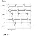
- FIG. 19shows typical duty cycles for sharing power between five loads.
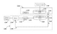
- the present disclosurerelates to an inductive power transmission platform 100 for accommodating a plurality of primary inductor units 200 a , 200 b , 200 c .
- the inductive power transmission surface 100may be incorporated, for example, into a table top for powering or charging electrical devices 320 , such as, inter alia, a laptop computer 320 a , a mobile phone 320 b and a standing lamp 320 c , placed thereupon.
- the transmission platform 100includes a plurality of power docks 120 , into which the primary inductor units 200 are affixable.
- the power docks 120may be arranged in a rectangular or staggered hexagonal (honeycomb) array.
- primary inductor units 200 a , 200 b , 200 cmay be positioned in any of the docks, and thus the arrangement of primary inductor units 200 may be varied to meet specific needs, perhaps on a custom basis.
- Electrical devices 320such as a computer 320 a , mobile telephone 320 b or a desk lamp 320 c , for example, may be provided with secondary inductors 322 for coupling with the primary inductor units 200 to draw power therefrom.
- Each primary inductor units 200may be secured into place at a dock 120 by a fastening means 122 such as clips arranged around the dock 120 .
- the primary inductive coil unit 200may be snap-fitted into a dock 120 by pushing it manually into position, and released therefrom by pulling. It will be apparent that other securing means such as clasps, sockets and the like may alternatively perform the function illustrated here by the clips 122 .
- the primary inductor units 200are connected to a power source by a supply power line 222 .
- Short-length connecting power lines 224 a , 224 bmay be used to connect a chain of primary inductor units 200 together.
- the power lines 222 , 224may be electrically coupled to the primary inductor units 200 via connecting plugs 240 .
- Power lines 222 , 224typically include two power cores 221 a and 221 b ( FIG. 2 ) for providing the varying potential used to power the primary inductor units 200 as well as a signal line 223 for providing a communications channel between a controller (not shown) and the primary inductor units 200 for controlling the power distribution. It will be appreciated that various connection configurations may be more amenable to certain applications such as hub configurations or the like as described below.
- the power platform 100is covered by a lid 140 , providing a generally smooth worktop 300 .
- a lid 140By aligning the secondary inductors 322 with primary inductor units 200 situated at access points 380 a - c below the smooth worktop 300 , power may be transferred to the associated electrical devices 320 .
- the inductive platform 100 described hereinaboveis a module adapted to be placed onto a desk-top.
- primary inductor units 200may be usefully affixed to or within other work surfaces such as within a desk-top, a kitchen work-top, a conference table, a work bench, as an under-floor arrangement or the like, which may optionally be covered to produce a generally smooth working area.
- primary inductor units 100may be embedded into non-horizontal surfaces such as the walls of a room, a ceiling, or the side of a cabinet for example.
- inductive power transferred from a suitable primary inductor unit 100may be used for recharging a mobile phone 320 b , as previously described in systems such as that described in U.S. Pat. No. 7,164,255 to Hui, referenced hereinabove, it is a particular feature of embodiments of the disclosure, that because the power may be supplied at specific (albeit user configurable) locations within the surface, and not generally simultaneously all over an extended surface, high power, even that sufficient for directly powering a computer 320 a , a desk lamp 320 c or the like, may be inductively provided where needed.
- FIG. 2One embodiment of a primary inductor unit 200 is represented in FIG. 2 .
- a coil 201 of conductive materialis nested between a central shaft 203 a and an encompassing ring 203 b of a ferromagnetic flux guiding core 203 , such as a ferrite material.
- a contact socket 205 on the outer surface 206 of the primary inductor unit 200is configured to receive the connecting plug 240 of a power line 220 .
- the power line 220is typically a three core cable having two power cores 221 a and 221 b as well as a signal line 223 .
- the primary inductor unit 200is secured to the power transmission surface 100 by being pushed into the power dock 120 where it may be fastened into place by a clip 122 or the like.
- the primary inductor units 200are movable within or over the surface to which they are attached or else removable therefrom. It will be apparent, therefore that the arrangement of the primary inductor units 200 may be configured and reconfigured, thereby allowing the transmission surface 300 to be customized to suit various and perhaps changing needs.
- the same power transmission platform 100is shown in two alternative configurations.
- Three primary inductor units 202 , 204 , 206are connected to three separate power docks 120 a , 120 b , 120 c respectively.
- Primary inductor units 200 a - cmay be suited for particular devices, so, for example a low power primary inductor unit 200 b may be optimized to recharge a mobile phone 320 b whereas a high power primary inductor 200 a may be optimized to power a computer 320 a and a medium power primary inductor 200 c may be optimized to power a desk lamp 320 c for example.
- a right handed usermay choose to customize the primary inductor units 200 a , 200 b ergonomically so that the mobile phone 320 b may be placed to the right of the computer 320 a , say, where it may be easily reached.
- a left handed usermay desire to reconfigure the power transmission platform 100 , as shown in FIG. 3 b , so that the lamp 320 c and the mobile telephone 320 b are situated to the left of the computer 320 a .
- Such a reconfigurationmay be achieved by rearranging the primary inductor units 200 on the power transmission platform 100 , connecting them to other power docks 120 d , 120 e , 120 f , located more conveniently for the requirements of the new configuration.
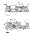
- FIGS. 4 a and 4 bshowing a modular power platform 110 according to another embodiment of the disclosure.
- the area of the required work surfaceis greater than the area of the individual module 110 more than one module may be coupled together to form a larger transmission surface 310 .
- Mechanical connectors 400such as clips, hook-and-eye connectors, magnets and the like, may be provided around the perimeter 420 of the module for releasably attaching two modules 110 mechanically.
- Electrical contacts 440may also be used to provide electrical communication between the power lines 224 of adjacent modules 110 .
- module tiles 110 a - gmay be coupled together both electrically and mechanically.
- Connectors 242may be used to electrically connect power lines 224 within each tile 110 to electrical contacts 440 on the tile perimeter, alternatively longer power lines 226 may be used to directly couple individual primary coil units.
- a horizontal transmission surface 310is thereby provided upon which electrical devices 320 may be placed.
- Electrical devices 320such as a computer 320 a , mobile telephone 320 b or a desk lamp 320 c , for example, may be provided with secondary inductive coils 322 for coupling with the primary coils 200 embedded within transmission surface 310 . Power may be transferred to the electrical devices 320 by aligning the secondary inductive coils 322 associated with the electrical devices 320 with access points 380 a - c upon the transmission surface 310 at which the primary coils 200 are located.
- any tessellating shapemay be used to produce a power transmission surface 310 .
- Tiles of any tessellating shapemay be used, such as quadrilaterals, triangles, square based pentagons, hexagons, etc.
- tilesmay be produced in complementary tessellating pairs, such as octagons and squares for example, so as to provide semi-regular tessellations, or an octagonal array with spaces therewithin may be provided.
- an extended cover 145may be provided for covering a plurality of tiles 110 , as well as the seams 112 between adjacent tiles 110 .
- a generally smooth transmission surface 310may be provided suitable for a variety of applications.
- FIGS. 6 a and 6 bStill another embodiment of the disclosure is shown in FIGS. 6 a and 6 b .
- a flexible base unitis configured as a strip 102 for inductively providing power to a plurality of electrical devices such as a laptop computer 520 .
- Primary inductor units 200 a - hare incorporated within a band 130 for inductively coupling with secondary inductors wired to the electrical devices. It is a particular feature of this embodiment of the present disclosure that the configuration of the band 130 may be adjusted to suit a plurality of needs.
- the usefulness of the flexible power strip 102may be illustrated by considering the following situation.
- One power strip 102may be closed into a band and overlaid upon a conference table 302 and used to power four laptop computers 520 a - d , each perhaps used by a different participant at a meeting.
- Each computer 520has a secondary coil unit 322 associated therewith.
- the secondary coil units 322may be external units 324 coupled to a computer by a connecting lead 326 , alternatively computers and the like may include hardwired integral secondary coils.
- a first configuration C 1 of the power strip 102may be selected such that there is at least one primary coil unit 200 a - d within reach of each computer 520 a - d .
- a fifth participantmay subsequently join the meeting bringing a fifth laptop 520 e computer, as shown in FIG. 5 b .
- the first configuration C 1was selected to best suit the needs of four computers 520 a - d , there may be no primary coil unit 200 within reach of the extra computer 520 e .
- the inherent flexibility of the power strip 102allows it to be adjusted into a second configuration C 2 in which an extra primary coil unit 200 e is brought into the vicinity of the extra computer 520 e.
- flexible power strips 102 of embodiments of the disclosuremay be placed on or incorporated within other work surfaces including desk-tops, kitchen work-tops, work benches, floors and the like. Indeed, the flexible strip 102 may also be vertically mounted on a wall for example.
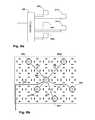
- FIGS. 6 a and 6 bAn exemplary flexible band 130 is shown in FIGS. 6 a and 6 b .
- a flexible materialis provided with ridged edges 132 .
- the flexible materialmay be inter alia an elastomer such as rubber, butadiene, neopropene or the like, a woven fabric, an unwoven fabric such as felt or the like.
- the flexible band 130may be arranged in a straight configuration as shown in FIG. 6 a in which the ridges 134 are all of the same dimensions.
- the band 130may be bent to provide a curved configuration as shown in FIG. 6 b wherein ridges 134 a - c long the outer edge 132 a are wider than the ridges 134 d - f along the inner edge 132 b.
- Alternative flexible strips or bandsmay include jointed sections, articulated frames or the like, which may be bent in at least one plane to provide a plurality of configurations of the band 130 .
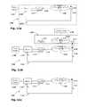
- primary inductor units 200 a - emay be arranged in a daisy-chain configuration controlled by a controller 260 wired to a power source.
- the primary inductor units 200are connected by connecting power lines 220 which conductively connect the primary coils 201 to the power source via switching units 270 a - e .
- the switching units 270 a - eare in communication with the controller 260 via a signal line 223 and are configured and operable to activate the primary coils 201 when they receive a signal.
- FIG. 7 bshows how the daisy-chain configuration may be incorporated into a power platform.
- the daisy-chain configurationmay be incorporated into other embodiments of the disclosure such as the modular power platform or flexible power platform as shown in FIG. 7 c and FIG. 7 d respectively.
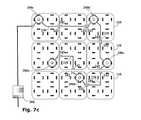
- FIG. 8 aan alternative hub-control configuration of the primary inductor units 200 a - e is shown.
- the primary inductor units 200 a - eare controlled centrally from a single control hub 280 which is wired to the power source.
- Each primary coil 201 a - eis conductively connected directly to the control hub 280 via power lines 220 .
- the control hub 280is thus able to directly and individually connect each primary coil 201 a - e to the power source.
- FIG. 8 bshows how the hub-control configuration may be incorporated into the power platform
- FIG. 8 cshows the hub-control configuration incorporated into a modular platform.
- Driving electronicsmay be provided by the controller 260 alongside a selector for selecting which primary coil 201 is to be driven.
- the driving electronicsmay be incorporated within the switching units 270 of the individual primary inductor units 200 and the controller 260 may serve to select the primary inductor unit(s) 200 to be activated.
- Power transmission modules 110comprising at least one power dock 120 are provided (step a).
- at least two power transmission modules 110are coupled together along a common edge to form a larger surface (step b).
- Primary inductor units 200are provided for inductively coupling with secondary inductive coils wired to electrical devices (step c).
- At least one primary inductor unit 200is incorporated within the power transmission surface (step d).
- Power lines 220are provided for providing power to the primary coil units (step e) and the primary inductor units 200 are electrically connected therewith (step f).
- An electrical device wired to a secondary inductoris provided (step g) and the secondary inductor is aligned to one of the primary inductor units 200 (step h).
- a varying electric potentialis applied to the primary inductive coil 201 via the power line 222 (step i) and the secondary inductive coil 322 inductively receives power transmitted by the primary inductive coil 201 thereby providing power to an electrical load coupled therewith.
- An adjustable flexible band 130is provided which may assume a plurality of configurations and which has at least one power dock 120 incorporated therein (step a′).
- Primary inductor units 200are provided for inductively coupling with secondary inductive coils wired to electrical devices (step b′). At least one primary coil unit 200 is docked to the flexible band (step c′).
- Power lines 220are provided for providing power to the primary inductor units (step d′) and the primary inductor units 200 are electrically connected therewith (step e′).
- the configuration of the flexible band 130is adjusted such that a primary inductor unit 200 is brought into the vicinity of an electrical device such as a computer 520 wired to a secondary inductive coil (step f).
- the secondary inductive coilis aligned to one of the primary inductor unit 200 of the strip 102 (step g′).
- a varying electric potentialis applied to the primary inductive coil 201 via the power line 222 (step h′) and the secondary inductive coil 322 inductively receives power transmitted by the primary inductive coil 201 thereby providing power to the electrical device 320 .
- power switchesare an important safety component in any power outlets since they may serve to cut off the power outlet from its power source. This is particularly important in inductive power outlets which do not typically require conductive contact to transmit power. In inductive power outlets, the power switches may be necessary to prevent power leakages.
- U.S. Pat. No. 6,803,744, to Sabo, titled “Alignment independent and self aligning inductive power transfer system”describes an inductive power transfer device for recharging cordless appliances.
- Sabo's deviceincludes a plurality of inductors which each serve as the primary coil of a transformer.
- the secondary coil of the transformeris arranged within the appliance. When the appliance is positioned proximate to the power transfer device with the primary and secondary coils in alignment, power is inductively transferred from the device to the appliance via the transformer.
- the inductors of Sabo's systemare arranged in an array and connected to a power supply via power switches, embedded in the power transfer device.
- the power switchesare selectively operable to activate associated inductors.
- the power switchesconserve power and prevent the transmission of electromagnetic fields from the inductors of the power transfer system.
- Such power switchesare switched each time an inductor is activated and deactivated and consequently deteriorate relatively quickly.
- the switchesare embedded within the power transfer device, they are not easily replaceable.
- FIG. 10showing a block diagram of the main features of a switching system 10 for controlling a primary inductive unit 20 according to various embodiments of the present disclosure.
- the primary inductive unit 20consists of a primary inductor 22 , wired to a power supply 24 , for inductively coupling with a secondary inductor 32 , housed in a secondary unit 30 , wired to an electric load 34 .
- the primary coil 22is wired to the power supply 24 via a driver 23 which provides the electronics necessary to drive the primary coil 22 .
- Driving electronicsprovides a high frequency oscillating voltage supply.
- the driver 23may additionally consist of a selector for selecting which primary coil 22 is to be driven.
- the power outlet 20is controlled by a switching system 10 consisting of a power switch 12 , for connecting the primary coil 22 to the driver 23 , and a sensing unit 14 in communication with the switch 12 and the driver 23 , for detecting a secondary coil 32 in proximity to the primary coil 22 .
- a switching system 10consisting of a power switch 12 , for connecting the primary coil 22 to the driver 23 , and a sensing unit 14 in communication with the switch 12 and the driver 23 , for detecting a secondary coil 32 in proximity to the primary coil 22 .
- the sensing unit 14detects that a secondary coil 32 is within range of the primary coil 22 , the power switch 12 is closed.
- Opening a closed switch while current is flowingmay cause arcing, with a spark formed across the gap. Such arcing or sparking is problematic as it can lead to deterioration or failure of the switch.
- Sparkingoccurs when the voltage drop between the contacts is large and the gap between the contacts is small enough that the voltage discharges across the gap. These conditions typically occur when a power switch is opened while current is passing through it. Sparking may corrode the contacts by the formation of an insulating oxide layer which prevents the contacts from forming a conductive bridge even when they are in contact with one another. Moreover, the effective contact area may be decreased due to erosion which increases the resistance and causes overheating and possibly even fire.
- power switch 12is not used to disconnect the primary coil 22 from the driver 23 while the primary coil 22 is active. Rather, when the sensing unit 14 detects that the secondary coil 32 has been moved out of range of the primary coil 22 , the driver 23 is deactivated before the power switch 12 is opened. Thus, the current stops flowing through the power switch 12 before the power switch 12 is opened. This prevents sparking between the contacts (not shown) of the power switch 12 .
- FIGS. 11 a - cA schematic diagram of an exemplary switching system 1100 for controlling an inductive power outlet 1200 is shown in FIGS. 11 a - c according to another embodiment of the disclosure.
- the switching system 1100consists of a reed switch 1120 , a solenoid 1122 and a secondary sensing unit 1140 .
- the reed switch 1120is configured to close when a magnet 1130 is brought into proximity therewith, the solenoid 1122 is configured to produce a magnetic field of sufficient magnitude to keep the reed switch 1120 closed and the secondary sensing unit 1140 is configured to detect the presence of a secondary coil 1320 .
- the reed switch 1120When closed, the reed switch 1120 connects a primary coil 1220 to a driver 1230 which is wired to a power supply 1240 . Additionally, the reed switch 1120 also connects the power supply 1240 to the solenoid 1122 . The solenoid 1122 thus produces a magnetic field which keeps the reed switch 1120 closed. In this way, once the reed switch 1120 has been closed by the magnet 1130 , the magnet 1130 can be removed without the reed switch 1120 opening.
- the reed switch 1120is protected from sparking because its contacts are held together by the magnetic field of the solenoid 1122 for as long as current flows therethrough.
- a reed switchis described hereabove, it is noted that in other embodiments of the disclosure, other magnetically sensitive switches such as Hall switches or the like may be used.
- the secondary sensing unit 1140is configured to detect when a secondary coil 1320 is inductively coupled to the primary coil 1220 . When a secondary coil 1320 is detected, an activation signal S 1 is sent to the driver 1230 , which then drives the primary coil 1220 . When the secondary coil 1320 is removed, the secondary sensing unit 1140 sends a deactivation signal S 0 to the driver 1230 , which then stops driving the primary coil 1220 .
- the secondary sensing unit 1140may include, for example, an optical receiver 1142 associated with the primary coil 1220 which is configured to receive a detection signal from an optical emitter 1144 associated with the secondary coil 1320 .
- the secondary sensing unit 1140may be configured to receive a detection signal such as some standard data signal of a type widely used in computing and telecommunications, for example an Infra-red, Wi-fi or Bluetooth signal or the like. Indeed, any light emitting diodes, radio transmitters, optocouplers, ultrasonic transducers or other such emitters may be used.
- a detection signalsuch as some standard data signal of a type widely used in computing and telecommunications, for example an Infra-red, Wi-fi or Bluetooth signal or the like.
- any light emitting diodes, radio transmitters, optocouplers, ultrasonic transducers or other such emittersmay be used.
- a reception circuitmay be incorporated within the driver for monitoring the power drawn from the primary coil.
- This reception circuitmay be configured to deactivate the driver when no load is detected.
- a corresponding transmission circuitcomprising an ancillary load connected to the secondary coil via a switching unit in parallel to the main electrical load, may be used to modulate the power received by the secondary coil so that data may be transferred to the reception circuit.
- FIG. 11 ashows the inductive power outlet 1200 in its inactive configuration with no secondary coil 1320 coupled thereto.
- the reed switch 1120is open and the primary coil 1220 is disconnected from the driver.
- a secondary unit 1300is shown aligned to the inductive power outlet 1200 .
- the secondary unit 1300comprises a secondary coil 1320 , wired to an electric load 1340 , a magnet 1130 , configured to close the reed switch 1120 and an optical emitter 1144 .
- the magnet 1320closes the reed switch 1120 connecting the driver 1230 to the primary coil 1220 .
- the detector 1142receives a detection signal from the emitter 1144 thereby activating the driver 1230 . Consequently, the primary coil 1220 transfers energy inductively to the secondary coil 1320 .
- the inductive power outlet 1200is shown during the short time interval between the secondary unit 1300 being removed and the driver 1230 being deactivated.
- the magnet 1130is no longer close enough to the reed switch 1120 to keep the reed switch 1120 closed (otherwise it is the magnet).
- the protective solenoid 1122is still connected to the active driver 1130 and therefore, itself provides a magnetic field of sufficient strength to keep the reed switch 1120 closed.
- the detector 1142no longer receives the detection signal from the emitter 1144 so a deactivation signal is passed to the driver 1230 which stops driving the primary coil 1220 .
- the driver 1230stops providing power to the primary coil 1220 , the protective solenoid 1122 is disconnected and the reed switch 1120 opens.
- the inductive power outlet 1200therefore adopts its inactive configuration as shown in FIG. 2 a . It is noted that, because the driver 1230 is deactivated before the reed switch 1120 opens, sparking is avoided since current stops flowing through the reed switch 1120 prior to being unplugged.
- FIG. 12shows a schematic diagram of a multicoil inductive power outlet 2200 controlled by protected power switches 2120 according to a further embodiment of the disclosure.
- the multicoil inductive power outlet 2200includes a cluster 2210 of primary inductive coils 2220 a - d . All of the primary inductive coils 2220 a - d are connected to a single driver 2230 via separate power switches 2120 a - d each protected by a solenoid 2122 a - d .
- the multicoil inductive power outletmay, for example, be incorporated into a flat surface 2400 , such as a desk top, to provide power inductively to electrical devices placed upon the surface 2400 .
- a secondary unit 2300is configured to receive power from the inductive power outlet 2200 .
- the secondary unit 2300consists of a secondary coil 2320 wired to an electrical load 2340 and a triggering mechanism 2130 , such as a magnet for closing a reed switch.
- Secondary units 2300may be inductive power receivers, integral or retrofitted to electrical devices such as computers, televisions and the like.
- the secondary unit 2300is located such that its triggering magnet 2130 closes the protected power switch 2120 a thereby connecting the associated primary inductive coil 2220 a to the driver 2230 .
- a secondary detector 2140 ais configured to send an activation signal to the driver 2230 indicating that the secondary inductive coil 2320 is coupled to the primary inductive coil 2220 a.
- the driver 2230When the driver 2230 receives the activation signal, an oscillating voltage is provided to the cluster 2210 . Although the driver 2230 provides the oscillating voltage to the whole cluster 2210 , only one of the power switches 2120 a is closed. Therefore only the primary inductive coil 2220 a associated with the closed power switch 2120 a is activated. All other primary coils 2220 b - d remain inactive.
- the secondary unit 2300is shown drawing power from one primary inductive coil 2220 a , it will be appreciated that the secondary unit 2300 may be alternatively aligned with any other primary inductive coil 2220 b - d.
- the trigger magnet 2130is removed from the associated power switch 2120 a but the switch 2120 a remains closed.
- the secondary detector 2140 adetects that the secondary coil 2320 is no longer coupled to the primary coil 2220 a and sends a deactivation signal to the driver 2230 .
- the driver 2230stops providing the oscillating voltage and the power switch 2120 a opens without sparking
- the secondary unit 2300may then be brought into alignment with another primary inductive coil 2220 b .
- the associated power switch 2120 bis closed by the triggering magnet 2130 and the secondary detector 2140 b sends an activation signal to the driver 2230 .
- two or more primary inductive coils 2220may be controlled by a common secondary detector 2140 .
- the secondary unit 2300additionally includes an internal power source 2330 , such as a voltaic cell, capacitor or the like, for providing power to the load 2340 during transition between the primary inductive coils 2220 . In this way the secondary unit 2300 may be moved between the primary inductive coils 2220 without a user noticing the transition.
- an internal power source 2330such as a voltaic cell, capacitor or the like
- the systemrequires minimal maintenance. Consequently, the power switches 2120 and primary coils 2220 may be embedded into surfaces 2400 , such as desktops, flat electrical appliances, walls, floors and so on.
- the central driver 2230which is a more costly component, may usefully be housed in a remote unit where it may be more easily accessed. This represents an advantage over prior art inductive power systems where each primary coil typically requires a separate driver or a specialized power switch.
- a large coil cluster 2210 with a high coil densitymay be incorporated with a single driver 2230 into a surface 2400 .
- powermay be provided to a secondary unit 2300 placed anywhere on the surface 2400 and even when the secondary unit 2300 is moved across the surface 2400 .
- the user experience of such a surface 2400is that the whole surface 2400 is power enabled.
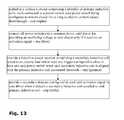
- FIG. 13is a flowchart illustrating a method for providing a low maintenance inductive power transmission said method comprising the following steps: embedding, in a surface, a cluster comprising a plurality of primary inductive coils each connected to a power switch, the power switch being configured to remain closed for as long as electric current passes therethrough—step (alpha); connecting all power switches to a common driver, the driver for providing an oscillating voltage to the cluster only if it receives an activation signal—step (beta); providing a inductive power receiver comprising a secondary inductive coil wired to an electric load and at least one trigger configured to close at least one power switch when the secondary inductive coil is aligned with the primary inductive coil associated therewith—step (gamma); and providing a secondary detector configured to send said activation signal to said driver when it detects a secondary inductive coil coupled to said primary inductive coil—step (delta).
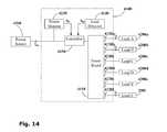
- the power distribution to the inductors of a multi-coil inductive outletmay be controlled by an energy management system.
- an exemplary energy management system 4100is shown coupled to a power source 4300 and connected to a plurality of loads 4200 a - f .
- the power source 4300is electrically coupled to a power board 4110 via a controller 4150 .
- the controller 4150is configured to receive a power signal Sp from a power monitor 4130 and a load signal S L from a load monitor 4140 .
- the power board 4300includes a plurality of electrical power jacks 4120 a - f which may be coupled to a plurality of electrical loads 4200 a - f.
- the load 4200When a load 4200 is coupled to a jack 4120 , the load 4200 is detected by the load detector 4140 .
- the load signal S Lrelays this information to the controller 4150 .
- the controller 4150provides power to the active jacks 4120 a , 4120 b and 4120 f which are connected to those loads 4200 a , 4200 b and 4200 f but not to the inactive jacks 4200 c , 4200 d and 4200 e to which no loads are connected.
- an additional load 4200 cis connected to an inactive jack 120 c then this load 200 c is detected by the load detector 4140 which sends a signal to the controller 4150 .
- the controller 4150then activates the inactive jack 4120 c thereby providing power to the new load 4200 c.
- the controller 4150is configured to regulate the power delivered to the power jacks 4120 a - f .
- the power monitor 4130monitors the power delivered to the power board 4110 and relays this information to the controller in the power signal S P .
- the controller 4150is preconfigured to provide power to the power jacks 4120 in a manner at least partially determined by the power signal S P . Power may be provided to more than one power jack 4120 in a number of ways, such as simultaneously, sequentially or intermittently, for example.
- An exemplary energy management systemmay be used to regulate the current I in being drawn by the power board 4100 from the power source 4300 .
- the controller 4150may be preconfigured to limit the current drawn I in from the power source 4300 such that it will not exceed a maximum value.
- the current drawn by the power board I independs upon the current i a-f drawn by all connected loads 4200 . When the connected loads 4200 a , 400 b and 4200 f draw too much current i a , i b and i f the current drawn I in from the power source 4300 may exceed its maximum value.
- the controller 4150may be preconfigured to sequentially switch between the active power jacks 4120 a , 4120 b and 4120 f according to a predetermined duty cycle.
- the total current drawn by the connected loads 4200 a , 4200 b and 4200 fis limited thereby, maintaining the current I in drawn by the power board at a level below its maximum value.
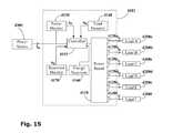
- FIG. 15showing a second embodiment of the energy management system 4101 having an energy reservoir 4160 such as a voltaic cell, a capacitor, a fuel cell, a super-capacitor, a flow battery, a superconducting magnetic energy store or the like.
- a reservoir monitor 4170is configured to monitor the energy level of the energy reservoir 4160 and relay this information to the controller 4151 in reservoir signal S R .
- the controller 4151is preconfigured to selectively charge up the energy reservoir 4160 , for example when the power signal Sp indicates that the power being drawn from the power source 4300 is low. This function may be used to provide a lower limit upon the drawn current I in .
- active power jacks 4120are intermittently connected to the power source 4300 according to a duty cycle.
- the energy reservoir 4160once it has been charged, may be used to provide power to active power jacks 4120 for the duration of the cycle when they are disconnected from the power source 4300 .
- uninterrupted poweris provided to all the loads 4200 a - f continuously.
- the efficiency of the system 4101may be optimized to minimize the power lost when operating within this precisely known range.
- the energy management system 4101may significantly reduce energy losses particularly when operating over long periods of time.
- each of the power jacks 4122 a - fhas an individually coupled energy reservoir 4162 a - f which are all monitored by a reservoir monitor 4172 .
- the controller 4152may control each jack 4122 and may switch between charging the reservoir 4162 , supplying power directly to the jack 4122 or both simultaneously.
- each load 4203 a - fcarries its own energy reservoir 4263 .
- Transmitters 4290 a - f in communication with the loadstransmit signals to a receiver 4190 in communication with the reservoir monitor 4173 thereby providing data regarding the power level of energy reservoirs 4263 .
- the coupled load 4203 a - fautomatically charges the energy reservoir 4263 a - f and directly powers the load 4203 a - f simultaneously.
- the controller 4153disconnects a power jack 4123 a - f
- the coupled load 4203 a - fautomatically draws power from its own energy reservoir 4263 a - f .
- the controller 4153 receiving the reservoir signal S Rmay thus be configured to provide power intermittently to each load 4203 a - f such that the power level of each reservoir 4263 a - f is maintained. In this manner each load 4200 is able to operate continuously and the power drawn from the power source 4300 is minimized.
- a power board 4114comprises an array of inductive power jacks 4124 , each inductive power jack 4124 has a primary inductive coil 1242 and a magnetic switch 1244 .
- Two computers 4204 a , 4204 b having onboard power cells 4264 a , 4264 bare coupled to the power board 4114 via inductive power plugs 4224 a , 4224 b .
- Each of the inductive power plugs 4224 a , 4224 bincludes a secondary inductive coil 2242 and a magnet 2244 .
- a power monitor 4134 , load detector 4144 and reservoir monitor 4174provide control signals for a controller 4154 which regulates the power drawn from a power source 4304 and delivered to the power jacks 4124 .
- Radio transmitters 4294 a , 4294 btransmit the power level of the onboard cells 4264 a , 4264 b to a receiver 4194 in communication with the reservoir monitor 4174 .
- the controllercan thereby monitor the level of the onboard cells 4264 of connected computers 4204 and selectively connect and disconnect the power jacks 4114 a , 4114 b thereby ensuring that the power drawn from the power source 4304 is minimized.
- the transmitters 4294are configured to be in close proximity to the receivers 4194 , they may be used to provide data-transfer at low power. By using low power Wi-fi or Bluetooth signals, for example, the power demanded by these applications may be minimized.
- Typical duty cycles for providing power to five loadsare shown in FIG. 6 .
- a constant power level Pis drawn throughout the duty cycle. However, this power is delivered sequentially to each of the five loads.
- Load Areceives power P for a short time interval ⁇ t 1 and is then disconnected for a longer interval ⁇ t off Once Load A is disconnected
- Load Bis connected for a time interval ⁇ t 2 and then switched off. All loads are connected sequentially over the time period ⁇ t of the duty cycle and then the cycle is repeated. Typically all loads are connected for equal time intervals ⁇ t 1-5 , however it will be appreciated that unequal time intervals may be accommodated.
- an adjustable platformfor providing movable inductive outlets.
- a useris able to position the inductive outlets as required.
- the inductive outletsmay be controllable separately allowing power to be provided by induction to a plurality of electrical loads.
- the power distribution to such loadsis controlled centrally allowing energy to be conserved.
Landscapes
- Engineering & Computer Science (AREA)
- Power Engineering (AREA)
- Computer Networks & Wireless Communication (AREA)
- Charge And Discharge Circuits For Batteries Or The Like (AREA)
- Coils Or Transformers For Communication (AREA)
- Remote Monitoring And Control Of Power-Distribution Networks (AREA)
Abstract
Description
- at least one power monitor for monitoring the power drawn by the power board and for producing a power signal;
- at least one load detector for detecting the presence of at least one load coupled with at least one power jack of the power board and producing a detection signal; and
- at least one controller for receiving the power signal from the power monitor and the detection signal from the load detector, selecting at least one power jack to be activated and controlling power delivered to the at least one power jack.
- providing at least one adjustable power supply module comprising said primary inductor;
- providing at least one secondary inductor;
- adjusting the configuration of said adjustable module such that said primary inductor is proximal said secondary inductor; and
- aligning said secondary inductor to said primary inductor.
- embedding in a module a cluster comprising a plurality of primary inductors each said primary inductor connected to a power switch, said power switch being configured to remain closed for as long as electric current passes therethrough;
- connecting all power switches to a common driver, said driver for providing an oscillating voltage to said cluster only if it receives an activation signal;
- providing a inductive power receiver comprising a secondary inductor wired to an electric load and at least one trigger configured to close at least one said power switch when said secondary inductor is aligned with the primary inductor associated therewith, and
- providing a secondary detector configured to send said activation signal to said driver when it detects a secondary inductor coupled to said primary inductor.
- providing at least one power monitor;
- providing at least one load detector;
- providing at least one controller;
- monitoring the power drawn by the power board and producing a power signal;
- detecting at least one load coupled with at least one power jack of the power board and producing a detection signal;
- the controller receiving the power signal and the detection signal;
- the controller selecting at least one power jack to be activated;
- the controller determining a duty cycle for connecting active power jacks; and
- connecting the active power jacks according to the duty cycle.
- external sensors such as volume sensors, infra-red sensors, ultrasonic sensors, hall probes or the like, perhaps using simple triangulation to locate the load4200;
- connecting load4200 to a jack4120 to close a detection circuit for example by pushing down a spring switch that is conductively connecting two contacts or the like.
- magnetic switches in the
power board 4110 that may detect the presence of a magnet embedded in the load4200, possibly using a magnetic key to identify the load; - transmitters4290 (
FIG. 17 ) embedded in the load4200 transmitting signals such as for example infra-red signals, radio signals or the like to a receiver4190 (FIG. 4 ) in theload detector 4140; - primary inductive coils in the
power board 4110 which may be used to locate a secondary inductive coil in a load4200 by scanning at low power and detecting additional power drawn by a load4200.
Claims (15)
Priority Applications (1)
| Application Number | Priority Date | Filing Date | Title |
|---|---|---|---|
| US12/731,559US8049370B2 (en) | 2007-09-25 | 2010-03-25 | Centrally controlled inductive power transmission platform |
Applications Claiming Priority (7)
| Application Number | Priority Date | Filing Date | Title |
|---|---|---|---|
| US96032107P | 2007-09-25 | 2007-09-25 | |
| US99619107P | 2007-11-06 | 2007-11-06 | |
| US99619007P | 2007-11-06 | 2007-11-06 | |
| US99625307P | 2007-11-08 | 2007-11-08 | |
| US7173208P | 2008-05-14 | 2008-05-14 | |
| PCT/IL2008/001282WO2009040807A2 (en) | 2007-09-25 | 2008-09-24 | Inductive power transmission platform |
| US12/731,559US8049370B2 (en) | 2007-09-25 | 2010-03-25 | Centrally controlled inductive power transmission platform |
Related Parent Applications (1)
| Application Number | Title | Priority Date | Filing Date |
|---|---|---|---|
| PCT/IL2008/001282ContinuationWO2009040807A2 (en) | 2007-09-25 | 2008-09-24 | Inductive power transmission platform |
Publications (2)
| Publication Number | Publication Date |
|---|---|
| US20100219698A1 US20100219698A1 (en) | 2010-09-02 |
| US8049370B2true US8049370B2 (en) | 2011-11-01 |
Family
ID=40511995
Family Applications (3)
| Application Number | Title | Priority Date | Filing Date |
|---|---|---|---|
| US12/731,559ActiveUS8049370B2 (en) | 2007-09-25 | 2010-03-25 | Centrally controlled inductive power transmission platform |
| US12/731,379Active2029-07-19US8456038B2 (en) | 2007-09-25 | 2010-03-25 | Adjustable inductive power transmission platform |
| US13/886,369ActiveUS8766488B2 (en) | 2007-09-25 | 2013-05-03 | Adjustable inductive power transmission platform |
Family Applications After (2)
| Application Number | Title | Priority Date | Filing Date |
|---|---|---|---|
| US12/731,379Active2029-07-19US8456038B2 (en) | 2007-09-25 | 2010-03-25 | Adjustable inductive power transmission platform |
| US13/886,369ActiveUS8766488B2 (en) | 2007-09-25 | 2013-05-03 | Adjustable inductive power transmission platform |
Country Status (9)
| Country | Link |
|---|---|
| US (3) | US8049370B2 (en) |
| EP (2) | EP2201581A4 (en) |
| JP (2) | JP2010541528A (en) |
| KR (2) | KR20100061845A (en) |
| CN (1) | CN101919011A (en) |
| AU (2) | AU2008303118A1 (en) |
| CA (1) | CA2700740A1 (en) |
| MX (1) | MX2010003273A (en) |
| WO (1) | WO2009040807A2 (en) |
Cited By (56)
| Publication number | Priority date | Publication date | Assignee | Title |
|---|---|---|---|---|
| US20100327801A1 (en)* | 2009-06-30 | 2010-12-30 | Lenovo (Singapore) Pte. Ltd. | Proximity power pad |
| US20110062793A1 (en)* | 2008-03-17 | 2011-03-17 | Powermat Ltd. | Transmission-guard system and method for an inductive power supply |
| US20110101791A1 (en)* | 2009-10-30 | 2011-05-05 | Tdk Corporation | Wireless power feeder, wireless power transmission system, and table and table lamp using the same |
| US20110234019A1 (en)* | 2007-08-17 | 2011-09-29 | Tmms Co., Ltd. | Method and device for transporting, distributing and managing electrical energy by remote longitudinal coupling in near field between electric dipoles |
| US20110278942A1 (en)* | 2010-05-11 | 2011-11-17 | Searete Llc, A Limited Liability Corporation Of The State Of Delaware | Wearable power source carryable by a health care provider |
| US20110278957A1 (en)* | 2010-05-11 | 2011-11-17 | Searete Llc, A Limited Liability Corporation Of The State Of Delaware | Wearable power source |
| US20120007437A1 (en)* | 2007-08-28 | 2012-01-12 | Access Business Group International Llc | Inductive power supply |
| US8169185B2 (en) | 2006-01-31 | 2012-05-01 | Mojo Mobility, Inc. | System and method for inductive charging of portable devices |
| US20120262005A1 (en)* | 2006-03-21 | 2012-10-18 | Murata Manufacturing Co., Ltd. | Device for transporting energy by partial influence through a dielectric medium |
| US8427014B2 (en) | 2010-05-11 | 2013-04-23 | The Invention Science Fund I, Llc | System including wearable power receiver and wearable power-output device |
| US20130154552A1 (en)* | 2011-02-02 | 2013-06-20 | Osram Ag | Energy Box Having an Inductive Charger, and a Method for Charging an Energy Box |
| US20140002016A1 (en)* | 2012-06-28 | 2014-01-02 | Siemens Aktiengesellschaft | Charging installation and method for inductively charging an electrical energy storage device |
| US8629652B2 (en) | 2006-06-01 | 2014-01-14 | Mojo Mobility, Inc. | Power source, charging system, and inductive receiver for mobile devices |
| US8829727B2 (en) | 2009-10-30 | 2014-09-09 | Tdk Corporation | Wireless power feeder, wireless power transmission system, and table and table lamp using the same |
| US8890470B2 (en) | 2010-06-11 | 2014-11-18 | Mojo Mobility, Inc. | System for wireless power transfer that supports interoperability, and multi-pole magnets for use therewith |
| US9106083B2 (en) | 2011-01-18 | 2015-08-11 | Mojo Mobility, Inc. | Systems and method for positioning freedom, and support of different voltages, protocols, and power levels in a wireless power system |
| US20150280442A1 (en)* | 2014-03-25 | 2015-10-01 | Apple Inc. | Tessellated inductive power transmission system coil configurations |
| US20150349571A1 (en)* | 2014-05-28 | 2015-12-03 | Apple Inc. | Electromagnetic alignment of inductive coils |
| US20160064944A1 (en)* | 2013-04-01 | 2016-03-03 | Nitto Denko Corporation | Power-receiving device |
| US20160094074A1 (en)* | 2013-10-23 | 2016-03-31 | Apple Inc. | Method and Apparatus for Inductive Power Transfer |
| US9331750B2 (en) | 2008-03-17 | 2016-05-03 | Powermat Technologies Ltd. | Wireless power receiver and host control interface thereof |
| US9337902B2 (en) | 2008-03-17 | 2016-05-10 | Powermat Technologies Ltd. | System and method for providing wireless power transfer functionality to an electrical device |
| US9356659B2 (en) | 2011-01-18 | 2016-05-31 | Mojo Mobility, Inc. | Chargers and methods for wireless power transfer |
| US9449754B2 (en) | 2014-05-30 | 2016-09-20 | Apple Inc. | Coil constructions for improved inductive energy transfer |
| US9496732B2 (en) | 2011-01-18 | 2016-11-15 | Mojo Mobility, Inc. | Systems and methods for wireless power transfer |
| US9577440B2 (en) | 2006-01-31 | 2017-02-21 | Mojo Mobility, Inc. | Inductive power source and charging system |
| US9722447B2 (en) | 2012-03-21 | 2017-08-01 | Mojo Mobility, Inc. | System and method for charging or powering devices, such as robots, electric vehicles, or other mobile devices or equipment |
| US9793739B2 (en) | 2013-08-07 | 2017-10-17 | Sandisk Technologies Llc | Wireless power transmitting device |
| US9837846B2 (en) | 2013-04-12 | 2017-12-05 | Mojo Mobility, Inc. | System and method for powering or charging receivers or devices having small surface areas or volumes |
| US20180109141A1 (en)* | 2014-03-03 | 2018-04-19 | The Wiremold Company | Wireless power stations |
| US9960642B2 (en) | 2008-03-17 | 2018-05-01 | Powermat Technologies Ltd. | Embedded interface for wireless power transfer to electrical devices |
| US9960640B2 (en) | 2008-03-17 | 2018-05-01 | Powermat Technologies Ltd. | System and method for regulating inductive power transmission |
| US10115520B2 (en) | 2011-01-18 | 2018-10-30 | Mojo Mobility, Inc. | Systems and method for wireless power transfer |
| US10283952B2 (en) | 2017-06-22 | 2019-05-07 | Bretford Manufacturing, Inc. | Rapidly deployable floor power system |
| US10404235B2 (en) | 2013-11-21 | 2019-09-03 | Apple Inc. | Using pulsed biases to represent DC bias for charging |
| US20200044468A1 (en)* | 2018-07-31 | 2020-02-06 | Ling Yung LIN | Mobile power supply module with light source |
| US10601250B1 (en) | 2016-09-22 | 2020-03-24 | Apple Inc. | Asymmetric duty control of a half bridge power converter |
| US10714985B2 (en) | 2017-10-11 | 2020-07-14 | Spark Connected LLC | Wireless power transfer system and method |
| US10978880B2 (en) | 2014-10-10 | 2021-04-13 | General Electric Company | System and method for contactless power transfer |
| US11114895B2 (en) | 2007-01-29 | 2021-09-07 | Powermat Technologies, Ltd. | Pinless power coupling |
| US11152823B2 (en) | 2019-04-01 | 2021-10-19 | Spark Connected LLC | Translation unit for wireless power transfer |
| US11159056B2 (en) | 2019-09-12 | 2021-10-26 | Spark Connected LLC | Wireless power receiver circuit and method |
| US11201500B2 (en) | 2006-01-31 | 2021-12-14 | Mojo Mobility, Inc. | Efficiencies and flexibilities in inductive (wireless) charging |
| US11211975B2 (en) | 2008-05-07 | 2021-12-28 | Mojo Mobility, Inc. | Contextually aware charging of mobile devices |
| US11329511B2 (en) | 2006-06-01 | 2022-05-10 | Mojo Mobility Inc. | Power source, charging system, and inductive receiver for mobile devices |
| US11387688B2 (en) | 2008-07-02 | 2022-07-12 | Powermat Technologies, Ltd. | System and method for coded communication signals regulating inductive power transmissions |
| US11398747B2 (en) | 2011-01-18 | 2022-07-26 | Mojo Mobility, Inc. | Inductive powering and/or charging with more than one power level and/or frequency |
| US11509169B2 (en) | 2019-02-13 | 2022-11-22 | Spark Connected LLC | Sub-surface wireless charging |
| US11515739B2 (en) | 2020-02-14 | 2022-11-29 | Spark Connected LLC | FOD and wireless power transfer calibration |
| US11811238B2 (en) | 2019-02-05 | 2023-11-07 | Mojo Mobility Inc. | Inductive charging system with charging electronics physically separated from charging coil |
| US11855463B2 (en) | 2020-12-04 | 2023-12-26 | Spark Connected LLC | Wireless power transmission to a mobile device |
| US11888331B2 (en) | 2020-07-01 | 2024-01-30 | Spark Connected LLC | Sub-surface wireless charging and associated method |
| US11979201B2 (en) | 2008-07-02 | 2024-05-07 | Powermat Technologies Ltd. | System and method for coded communication signals regulating inductive power transmissions |
| US11984731B2 (en) | 2014-12-22 | 2024-05-14 | The Wiremold Company | Ecosystem for surface-based wireless charging system |
| US12053055B2 (en) | 2020-05-15 | 2024-08-06 | Spark Connected LLC | Dual function wireless power and thermal receiver |
| US12068631B2 (en) | 2020-04-13 | 2024-08-20 | Spark Connected LLC | Alignment method for sub-surface wireless charger |
Families Citing this family (91)
| Publication number | Priority date | Publication date | Assignee | Title |
|---|---|---|---|---|
| EP3975372B1 (en) | 2007-03-22 | 2024-01-31 | Powermat Technologies Ltd. | Efficiency monitor for inductive power transmission |
| US10068701B2 (en) | 2007-09-25 | 2018-09-04 | Powermat Technologies Ltd. | Adjustable inductive power transmission platform |
| KR20100061845A (en) | 2007-09-25 | 2010-06-09 | 파우워매트 엘티디. | Adjustable inductive power transmission platform |
| US8193769B2 (en) | 2007-10-18 | 2012-06-05 | Powermat Technologies, Ltd | Inductively chargeable audio devices |
| US20100219183A1 (en) | 2007-11-19 | 2010-09-02 | Powermat Ltd. | System for inductive power provision within a bounding surface |
| US8536737B2 (en) | 2007-11-19 | 2013-09-17 | Powermat Technologies, Ltd. | System for inductive power provision in wet environments |
| US8884468B2 (en) | 2007-12-21 | 2014-11-11 | Access Business Group International Llc | Circuitry for inductive power transfer |
| US8338990B2 (en)* | 2008-03-13 | 2012-12-25 | Access Business Group International Llc | Inductive power supply system with multiple coil primary |
| WO2014072975A1 (en)* | 2012-11-07 | 2014-05-15 | Powermat Technologies Ltd. | Embedded interface for wireless power transfer to electrical devices |
| US8320143B2 (en) | 2008-04-15 | 2012-11-27 | Powermat Technologies, Ltd. | Bridge synchronous rectifier |
| US8242880B2 (en) | 2008-05-29 | 2012-08-14 | Georgia Tech Research Corporation | Tongue operated magnetic sensor systems and methods |
| AU2009254785A1 (en) | 2008-06-02 | 2009-12-10 | Powermat Technologies Ltd. | Appliance mounted power outlets |
| US8188619B2 (en) | 2008-07-02 | 2012-05-29 | Powermat Technologies Ltd | Non resonant inductive power transmission system and method |
| WO2010004560A1 (en) | 2008-07-08 | 2010-01-14 | Powermat Ltd. | Display device |
| EP2342797A2 (en) | 2008-09-23 | 2011-07-13 | Powermat Ltd | Combined antenna and inductive power receiver |
| US9178376B2 (en) | 2008-12-12 | 2015-11-03 | Hanrim Postech Co., Ltd. | Non-contact charging station with power transmission planar spiral core, non-contact power-receiving apparatus, and method for controlling the same |
| RU2011132944A (en)* | 2009-01-06 | 2013-02-20 | Эксесс Бизнесс Груп Интернешнл Ллс | INDUCTIVE POWER SUPPLY |
| AU2010234396A1 (en)* | 2009-04-08 | 2011-10-27 | Access Business Group International Llc | Selectable coil array |
| US9124308B2 (en) | 2009-05-12 | 2015-09-01 | Kimball International, Inc. | Furniture with wireless power |
| WO2010132578A1 (en) | 2009-05-12 | 2010-11-18 | Kimball International, Inc. | Furniture with wireless power |
| RU2548367C2 (en)* | 2009-07-13 | 2015-04-20 | Конинклейке Филипс Электроникс Н.В. | Energy inductive transmission |
| CA2768397A1 (en) | 2009-07-24 | 2011-01-27 | Access Business Group International Llc | Power supply |
| US8290463B2 (en) | 2009-09-14 | 2012-10-16 | ConvenientPower HK Ltd. | Universal demodulation and modulation for data communication in wireless power transfer |
| US8482160B2 (en)* | 2009-09-16 | 2013-07-09 | L & P Property Management Company | Inductively coupled power module and circuit |
| JP4669560B1 (en)* | 2009-12-11 | 2011-04-13 | エンパイア テクノロジー ディベロップメント エルエルシー | Contactless information management / charging system, mobile communication terminal and contactless information / power transmission unit |
| WO2011077488A1 (en)* | 2009-12-24 | 2011-06-30 | 株式会社 東芝 | Wireless power transmission apparatus |
| EP2519424A2 (en) | 2009-12-28 | 2012-11-07 | Toyoda Gosei Co., Ltd. | Recharging or connection tray for portable electronic devices |
| JP2011151900A (en)* | 2010-01-19 | 2011-08-04 | Panasonic Electric Works Co Ltd | Contactless power supply system |
| JP5537168B2 (en)* | 2010-01-19 | 2014-07-02 | パナソニック株式会社 | Planar structure with contactless power supply function |
| WO2011135571A2 (en) | 2010-04-30 | 2011-11-03 | Powermat Ltd. | System and method for transfering power inductively over an extended region |
| US9356383B2 (en) | 2010-05-28 | 2016-05-31 | Koninklijke Philips N.V. | Transmitter module for use in a modular power transmitting system |
| JP5691337B2 (en)* | 2010-09-17 | 2015-04-01 | ソニー株式会社 | Power supply system, charge control device, and battery device |
| WO2012093398A2 (en) | 2011-01-05 | 2012-07-12 | Powermat Technologies Ltd. | System and method for integrating inductive power functionality into furniture |
| US9166440B2 (en)* | 2011-01-10 | 2015-10-20 | Powermat Technologies Ltd. | System for transferring power inductively to items within a container |
| JP2012175806A (en)* | 2011-02-22 | 2012-09-10 | Panasonic Corp | Non-contact type feeding device |
| US20130057203A1 (en)* | 2011-03-01 | 2013-03-07 | Neil Jones | Assembly for mounting an inductive charger base station to a furniture work surface |
| US8947043B2 (en)* | 2011-05-25 | 2015-02-03 | Teknion Limited | Light with integrated inductive charger base station |
| CN102354764B (en)* | 2011-08-24 | 2013-11-20 | 中国东方电气集团有限公司 | Energy supply system and control method thereof |
| US8553408B2 (en) | 2011-09-06 | 2013-10-08 | Dana Innovations | Charging docking system |
| US8847436B2 (en)* | 2011-09-12 | 2014-09-30 | Lighting Science Group Corporation | System for inductively powering an electrical device and associated methods |
| JP5817500B2 (en)* | 2011-12-16 | 2015-11-18 | 株式会社Ihi | Power feeding system and non-contact power feeding method |
| WO2013108321A1 (en)* | 2012-01-17 | 2013-07-25 | 日本電気株式会社 | Power supply system |
| LT2625985T (en)* | 2012-02-07 | 2017-10-10 | Kih-Utveckling Ab | Power distribution control of a furniture arrangment |
| JP5903624B2 (en) | 2012-03-09 | 2016-04-13 | パナソニックIpマネジメント株式会社 | Non-contact power transmission device driving method and non-contact power transmission device |
| US20130303024A1 (en)* | 2012-05-09 | 2013-11-14 | Kyo Nagase Rapp | Safety Electrical Interconnect |
| US9294149B2 (en) | 2012-05-14 | 2016-03-22 | Brewsterpearah Ventures Llc | Integrated contactless connectivity platform for portable electronic devices |
| KR101438910B1 (en)* | 2012-10-04 | 2014-09-11 | 엘지이노텍 주식회사 | The Wired-Wireless Combined Power Transmission Apparatus and The Method using the same |
| US9376026B2 (en) | 2012-10-19 | 2016-06-28 | Qualcomm Incorporated | System and method for inductance compensation in wireless power transfer |
| US20150288195A1 (en)* | 2012-11-07 | 2015-10-08 | Rotem Shraga | Adaptable inductive power receiver for electrical devices |
| US20170364679A1 (en)* | 2016-06-17 | 2017-12-21 | Hewlett Packard Enterprise Development Lp | Instrumented versions of executable files |
| WO2015017671A2 (en)* | 2013-08-01 | 2015-02-05 | Urbaneer LLC | Apparatus and method for reconfigurable space |
| CA2865739C (en) | 2013-09-30 | 2018-12-04 | Norman R. Byrne | Wireless power for portable articles |
| CA2865457C (en) | 2013-09-30 | 2019-01-22 | Norman R. Byrne | Articles with electrical charging surfaces |
| US9722352B2 (en) | 2013-12-08 | 2017-08-01 | Henge Docks Llc | Mounting system for an electronic device |
| KR102181156B1 (en)* | 2014-03-07 | 2020-11-20 | 삼성전자주식회사 | Cover member, electronic device and method for wireless charging |
| US10312731B2 (en)* | 2014-04-24 | 2019-06-04 | Westrock Shared Services, Llc | Powered shelf system for inductively powering electrical components of consumer product packages |
| US20170135490A1 (en)* | 2014-06-11 | 2017-05-18 | Gentherm Incorporated | Office climate control system and method |
| US11103715B2 (en)* | 2014-06-27 | 2021-08-31 | Cochlear Limited | Devices and methods for charging medical devices |
| US10148163B2 (en) | 2014-07-17 | 2018-12-04 | Albert James Lovshin | Systems and methods for collecting, storing, and using electrical energy from the earth magnetic field |
| WO2016028704A1 (en)* | 2014-08-19 | 2016-02-25 | Lovshin Albert James | Systems and methods for collecting, storing, and using electrical energy from the earth magnetic field |
| CN105743143A (en)* | 2014-12-10 | 2016-07-06 | 天津市中环通讯技术有限公司 | Embedded installation method for installing wireless charger at bottom of desk |
| CN105790335A (en)* | 2014-12-24 | 2016-07-20 | 比亚迪股份有限公司 | Wireless charging system and wireless charging method |
| US10181735B2 (en) | 2015-03-11 | 2019-01-15 | Norman R. Byrne | Portable electrical power unit |
| DE102015206365A1 (en) | 2015-04-09 | 2016-10-13 | Bayerische Motoren Werke Aktiengesellschaft | Cover for electromagnetic coil |
| CN106329679A (en)* | 2015-06-26 | 2017-01-11 | 苏州宝时得电动工具有限公司 | Wireless charging alignment device and wireless charging device |
| GB2543344A (en)* | 2015-10-16 | 2017-04-19 | Bombardier Transp Gmbh | An inductive power transfer unit, a system for inductive power transfer and a method of communicating |
| CN106887906B (en) | 2015-12-16 | 2024-06-18 | 泰科电子(上海)有限公司 | Wireless power supply device and electrical equipment |
| MX383881B (en) | 2016-03-11 | 2025-03-14 | Norman R Byrne | Furniture-mounted charging station |
| US10000134B2 (en) | 2016-03-28 | 2018-06-19 | Denso International America, Inc. | Wireless charging system for charging vehicular battery |
| US9941719B2 (en)* | 2016-05-18 | 2018-04-10 | International Business Machines Corporation | Wireless charging surface |
| US20170353046A1 (en)* | 2016-06-02 | 2017-12-07 | Qualcomm Incorporated | Modular and assemblable wireless charging system and device |
| US10988940B2 (en) | 2016-06-03 | 2021-04-27 | Norman R. Byrne | Surface-mounted resonators for wireless power |
| ITUA20164413A1 (en)* | 2016-06-15 | 2017-12-15 | Simone Marini | Multi-purpose container that can be opened, also with the function of building tile for lighting applications, home automation and audio amplification |
| CN109217485A (en)* | 2017-07-05 | 2019-01-15 | 泰科电子(上海)有限公司 | Wireless power supply and electrical equipment |
| MX387762B (en) | 2017-07-24 | 2025-03-18 | Norman R Byrne | Furniture-mounted electrical charging station |
| WO2019051201A1 (en) | 2017-09-08 | 2019-03-14 | Sobota Rodriguez Cristian | Opto-inductive coupling system and method for wireless charging and data communications |
| TWM558564U (en)* | 2017-11-02 | 2018-04-21 | Zheng zhong sheng | Smart table |
| US10633911B2 (en)* | 2017-11-10 | 2020-04-28 | Loungera Ip Llc | Outdoor chaise lounge with integrated lock-box and communications system |
| TWM556965U (en)* | 2017-12-20 | 2018-03-11 | 宏芯科技股份有限公司 | Wireless charging device |
| WO2019199740A1 (en)* | 2018-04-09 | 2019-10-17 | CTOP Wireless Charging Solutions LLC | System and method for switchable multi-coil wireless induction charging |
| KR102602642B1 (en)* | 2018-09-18 | 2023-11-16 | 삼성전자주식회사 | Wireless charging device |
| CN110011389B (en)* | 2019-05-22 | 2021-01-08 | 维沃移动通信有限公司 | a wireless charger |
| USD979280S1 (en) | 2019-05-28 | 2023-02-28 | Norman R. Byrne | Drape-over article with storage |
| US10939767B2 (en)* | 2019-06-27 | 2021-03-09 | Sam Allen | Locker with inductive charger |
| FR3109052B1 (en)* | 2020-04-07 | 2023-12-15 | Ipan Ipan | Wireless charging or power supply system |
| KR102620690B1 (en)* | 2021-07-23 | 2024-01-05 | 주식회사 원인터내셔널 | Wireless charging device that can be customized according to the user's needs |
| US11920771B2 (en)* | 2021-11-05 | 2024-03-05 | Hb Innovations, Inc. | Multi-colored night light with sound output imitating breathing pattern cadence |
| CN115168079B (en)* | 2022-09-08 | 2022-12-02 | 深圳市恒运昌真空技术有限公司 | Dual-processor device and control method thereof |
| JP2024050220A (en)* | 2022-09-29 | 2024-04-10 | トヨタ自動車株式会社 | Non-contact power supply device |
| DE102023112570A1 (en)* | 2023-05-12 | 2024-11-14 | Bayerische Motoren Werke Aktiengesellschaft | CHARGING ARRANGEMENT FOR WIRELESS CHARGING OF A RECHARGEABLE ELECTRICAL ENERGY STORAGE UNIT OF A MOBILE DEVICE |
| US20250211024A1 (en)* | 2023-12-21 | 2025-06-26 | Jong Whee JEON | Systems, devices, and methods for wirelessly transmitting power |
Citations (140)
| Publication number | Priority date | Publication date | Assignee | Title |
|---|---|---|---|---|
| US3771085A (en) | 1971-08-10 | 1973-11-06 | Tokyo Keiki Kk | Deviation detecting apparatus |
| US3938018A (en) | 1974-09-16 | 1976-02-10 | Dahl Ernest A | Induction charging system |
| US4160193A (en) | 1977-11-17 | 1979-07-03 | Richmond Abraham W | Metal vapor electric discharge lamp system |
| US4431948A (en) | 1982-08-09 | 1984-02-14 | Standun Controls, Inc. | Apparatus for control of load power consumption |
| EP0160990A2 (en) | 1984-05-11 | 1985-11-13 | Telefunken Systemtechnik Gmbh | Inductive transmission of power and data |
| US4754180A (en) | 1985-04-01 | 1988-06-28 | Honeywell Inc. | Forceless non-contacting power transformer |
| US4977515A (en) | 1988-08-29 | 1990-12-11 | Rudden Frank G | Load management device and method of use |
| US5221877A (en) | 1992-03-10 | 1993-06-22 | Davis Controls Corporation | Power reduction control for inductive lighting installation |
| US5229650A (en)* | 1990-11-07 | 1993-07-20 | Yuasa Battery Company Limited | Uniterruptible power system |
| EP0558316A1 (en) | 1992-02-27 | 1993-09-01 | G2 Design Limited | An inductive loop power transmission system |
| US5278771A (en) | 1991-07-12 | 1994-01-11 | Seti Corporation | Programmable timed electrical power management device |
| US5367242A (en) | 1991-09-20 | 1994-11-22 | Ericsson Radio Systems B.V. | System for charging a rechargeable battery of a portable unit in a rack |
| US5455466A (en) | 1993-07-29 | 1995-10-03 | Dell Usa, L.P. | Inductive coupling system for power and data transfer |
| US5486394A (en) | 1994-08-26 | 1996-01-23 | E-Z Taping System, Inc. | Self-release self-adhesive drywall tape |
| WO1996002879A1 (en) | 1994-07-19 | 1996-02-01 | Elonex Technologies, Inc. | Micro personal digital assistant |
| US5528113A (en) | 1993-10-21 | 1996-06-18 | Boys; John T. | Inductive power pick-up coils |
| US5550452A (en) | 1993-07-26 | 1996-08-27 | Nintendo Co., Ltd. | Induction charging apparatus |
| US5600225A (en) | 1994-06-30 | 1997-02-04 | Nippon Electric Co | Noncontacting charging device |
| US5713939A (en) | 1996-09-16 | 1998-02-03 | Sulzer Intermedics Inc. | Data communication system for control of transcutaneous energy transmission to an implantable medical device |
| US5734254A (en) | 1996-12-06 | 1998-03-31 | Hewlett-Packard Company | Battery pack and charging system for a portable electronic device |
| US5762250A (en) | 1994-07-06 | 1998-06-09 | Truckin' Movers Corporation | Convertible carrying case and work platform for small electronic devices |
| US5821728A (en) | 1996-07-22 | 1998-10-13 | Schwind; John P. | Armature induction charging of moving electric vehicle batteries |
| US5821731A (en) | 1996-01-30 | 1998-10-13 | Sumitomo Wiring Systems, Ltd. | Connection system and connection method for an electric automotive vehicle |
| US5907285A (en) | 1993-12-09 | 1999-05-25 | Steelcase Inc. | Furniture unit having a modular communication network |
| US5929598A (en) | 1996-07-03 | 1999-07-27 | Uniden Corporation | Noncontact charging device, charger, cordless electric equipment, and noncontact charger |
| US5949214A (en) | 1997-11-04 | 1999-09-07 | Input/Output, Inc. | Rechargeable battery pack |
| US6042005A (en) | 1997-06-20 | 2000-03-28 | Basile; Mark R. | Personal identification and promotional system using personal and medical information |
| US6211649B1 (en) | 1999-03-25 | 2001-04-03 | Sourcenext Corporation | USB cable and method for charging battery of external apparatus by using USB cable |
| US6230029B1 (en) | 1998-01-07 | 2001-05-08 | Advanced Mobile Solutions, Inc. | Modular wireless headset system |
| WO2002001557A1 (en) | 2000-06-27 | 2002-01-03 | Citizen Watch Co., Ltd. | Disk drive |
| WO2002015320A1 (en) | 2000-08-16 | 2002-02-21 | Inca Systems Co., Ltd. | Battery charging system and battery charging apparatus thereof |
| US20020057584A1 (en) | 2000-11-14 | 2002-05-16 | Salcomp Oy | Power supply arrangement and inductively coupled battery charger with wirelessly coupled control, and method for wirelessly controlling a power supply arrangement and an inductively coupled battery charger |
| US6396935B1 (en) | 1996-01-26 | 2002-05-28 | Veijo Sakari Makkonen | Headset and method for a headset |
| US6436299B1 (en) | 1999-06-21 | 2002-08-20 | Amway Corporation | Water treatment system with an inductively coupled ballast |
| US6441589B1 (en) | 2001-04-02 | 2002-08-27 | Bellsouth Intellectual Property Corporation | Portable battery recharge station |
| US20020158512A1 (en) | 2001-04-26 | 2002-10-31 | Satoshi Mizutani | Mounting structure including communication system for transmitting multiplex control signal to vehicle electrical devices |
| US6484260B1 (en) | 1998-04-24 | 2002-11-19 | Identix, Inc. | Personal identification system |
| US6532298B1 (en) | 1998-11-25 | 2003-03-11 | Iridian Technologies, Inc. | Portable authentication device and method using iris patterns |
| US6586909B1 (en) | 2001-12-21 | 2003-07-01 | Ron Trepka | Parallel battery charging device |
| US6644557B1 (en) | 2002-03-25 | 2003-11-11 | Robert A Jacobs | Access controlled thermostat system |
| US20030210106A1 (en) | 2002-05-13 | 2003-11-13 | Splashpower Limited, A Company Incorporated In The Uk | Contact-less power transfer |
| US6673250B2 (en) | 1999-06-21 | 2004-01-06 | Access Business Group International Llc | Radio frequency identification system for a fluid treatment system |
| US20040023633A1 (en) | 2002-07-31 | 2004-02-05 | Gordon Mark A. | Handheld wireless device holder |
| US6721540B1 (en) | 1999-03-19 | 2004-04-13 | Seiko Epson Corporation | Electronic device |
| US6731071B2 (en) | 1999-06-21 | 2004-05-04 | Access Business Group International Llc | Inductively powered lamp assembly |
| US6766040B1 (en) | 2000-10-02 | 2004-07-20 | Biometric Solutions, Llc | System and method for capturing, enrolling and verifying a fingerprint |
| GB2399466A (en) | 2003-03-10 | 2004-09-15 | Univ City Hong Kong | Battery charging system |
| US20040195767A1 (en) | 2002-12-10 | 2004-10-07 | Mitch Randall | Systems and methods for providing electric power to mobile and arbitrarily positioned devices |
| US6803744B1 (en)* | 1999-11-01 | 2004-10-12 | Anthony Sabo | Alignment independent and self aligning inductive power transfer system |
| US20040203537A1 (en) | 2003-04-14 | 2004-10-14 | Shikio Yoshida | Wireless transmission module |
| US6825620B2 (en) | 1999-06-21 | 2004-11-30 | Access Business Group International Llc | Inductively coupled ballast circuit |
| US20040242264A1 (en) | 2003-01-09 | 2004-12-02 | Samsung Electronics Co., Ltd. | Communication device and wireless headset apparatus |
| US20040261802A1 (en) | 2003-06-30 | 2004-12-30 | Griffin William T. | Stand for electrically heated cigarette smoking device |
| US20050007067A1 (en) | 1999-06-21 | 2005-01-13 | Baarman David W. | Vehicle interface |
| US20050083020A1 (en) | 2003-10-20 | 2005-04-21 | Baarman David W. | Electrostatic charge storage assembly |
| US6888438B2 (en) | 2001-06-15 | 2005-05-03 | City University Of Hong Kong | Planar printed circuit-board transformers with effective electromagnetic interference (EMI) shielding |
| US6894457B2 (en) | 2002-11-01 | 2005-05-17 | American Power Conversion Corporation | Universal multiple device power adapter and carry case |
| US20050130593A1 (en) | 2003-12-16 | 2005-06-16 | Michalak Gerald P. | Integrated wireless headset |
| US20050169506A1 (en) | 2004-01-07 | 2005-08-04 | Identification International, Inc. | Low power fingerprint capture system, apparatus, and method |
| US20050192062A1 (en) | 2002-09-18 | 2005-09-01 | Mickle Marlin H. | Recharging method and apparatus |
| US20050233768A1 (en) | 2004-04-16 | 2005-10-20 | Hon Hai Precision Industry Co., Ltd. | Wireless transmitter and earphone based on 802.11a/b/g standard |
| US20060028176A1 (en) | 2004-07-22 | 2006-02-09 | Qingfeng Tang | Cellular telephone battery recharging apparatus |
| WO2006015143A2 (en) | 2004-07-28 | 2006-02-09 | Newton Peripherals, Llc | Peripheral devices for portable computer |
| US20060043927A1 (en) | 2002-09-27 | 2006-03-02 | Splashpower Limited | Retention of rechargeable devices |
| US20060052144A1 (en) | 2004-09-08 | 2006-03-09 | Seil Oliver D | Holder, electrical supply, and RF transmitter unit for electronic devices |
| US20060061325A1 (en) | 2004-09-21 | 2006-03-23 | Qingfeng Tang | Apparatus for inductively recharging batteries |
| US20060071632A1 (en) | 2004-09-24 | 2006-04-06 | Riad Ghabra | Efficient inductive battery recharging system |
| USD519275S1 (en) | 2005-03-09 | 2006-04-25 | Tbac Investment Trust | Carrier for digital player and headphones |
| US20060093132A1 (en) | 2004-08-30 | 2006-05-04 | Innovi Technologies Limited | Wireless earpiece for cell phone |
| US20060091222A1 (en) | 2004-10-25 | 2006-05-04 | Empower Technologies Inc. | Direct-mounted pouch for portable electronic device |
| US7043060B2 (en) | 2001-07-17 | 2006-05-09 | Niccole Family Trust | Fingerprint-actuated padlock |
| US20060202665A1 (en) | 2005-03-10 | 2006-09-14 | Microsoft Corporation | Inductive powering surface for powering portable devices |
| US7126450B2 (en) | 1999-06-21 | 2006-10-24 | Access Business Group International Llc | Inductively powered apparatus |
| US7164255B2 (en) | 2002-06-10 | 2007-01-16 | City University Of Hong Kong | Inductive battery charger system with primary transformer windings formed in a multi-layer structure |
| US20070023559A1 (en) | 2005-07-26 | 2007-02-01 | James Scapillato | Electronic device case |
| US7180265B2 (en) | 2001-06-29 | 2007-02-20 | Nokia Corporation | Charging device with an induction coil |
| US20070057763A1 (en) | 2005-09-12 | 2007-03-15 | Imation Corp. | Wireless handheld device with local biometric authentication |
| US20070076459A1 (en) | 2003-05-02 | 2007-04-05 | Limpkin George A | Apparatus for supplying energy to a load and a related system |
| US7224086B2 (en) | 2002-11-01 | 2007-05-29 | American Power Conversion Corporation | Universal multiple device power adapter and carry case |
| US20070136593A1 (en) | 2005-12-14 | 2007-06-14 | Richard Plavcan | Secure information storage apparatus |
| US20070165371A1 (en) | 2006-01-13 | 2007-07-19 | Marware, Inc. | Portable digital media player case |
| US20070182367A1 (en) | 2006-01-31 | 2007-08-09 | Afshin Partovi | Inductive power source and charging system |
| USD553852S1 (en) | 2006-01-13 | 2007-10-30 | Marware, Inc. | Portable digital media player case |
| US20070279002A1 (en) | 2006-06-01 | 2007-12-06 | Afshin Partovi | Power source, charging system, and inductive receiver for mobile devices |
| US20080030985A1 (en) | 2006-08-07 | 2008-02-07 | Eun-Chae Jeon | Backlight assembly and display apparatus having the same |
| US20080049988A1 (en) | 2004-04-06 | 2008-02-28 | Biometrx Technologies, Inc | Method of, and System for, Accessing a Home or Dwelling |
| WO2008030985A2 (en) | 2006-09-06 | 2008-03-13 | Newton Peripherals Llc | Wireless headset |
| US20080067874A1 (en)* | 2006-09-14 | 2008-03-20 | Ryan Tseng | Method and apparatus for wireless power transmission |
| US20080079388A1 (en) | 2006-10-03 | 2008-04-03 | Visteon Global Technologies, Inc. | Wireless charging device |
| US7385357B2 (en) | 1999-06-21 | 2008-06-10 | Access Business Group International Llc | Inductively coupled ballast circuit |
| US7392068B2 (en) | 2002-03-01 | 2008-06-24 | Mobilewise | Alternative wirefree mobile device power supply method and system with free positioning |
| US20080157715A1 (en) | 2006-01-07 | 2008-07-03 | Egate-International Gmbh | Plug-type charger for small electrical device |
| WO2008086080A2 (en) | 2007-01-03 | 2008-07-17 | Newton Peripherals, Llc | Dongle device |
| WO2008093334A2 (en) | 2007-01-29 | 2008-08-07 | Powermat Ltd | Pinless power coupling |
| US20080223926A1 (en) | 2007-03-01 | 2008-09-18 | Miller Brian S | Biometric control of equipment |
| WO2008114268A2 (en) | 2007-03-22 | 2008-09-25 | Powermat Ltd | Signal transfer system |
| US20080265835A1 (en) | 2007-04-26 | 2008-10-30 | Visteon Global Technologies, Inc. | Wireless power transfer system |
| EP1990734A1 (en) | 2007-05-09 | 2008-11-12 | Menstecnica S.R.L. | Portable and independent system for storage and display of passwords and pins |
| US7462951B1 (en) | 2004-08-11 | 2008-12-09 | Access Business Group International Llc | Portable inductive power station |
| US20090026959A1 (en) | 2007-07-27 | 2009-01-29 | Jung Tsung Lin | Non-contact light emitting display for vehicle |
| US20090040807A1 (en) | 2007-08-06 | 2009-02-12 | Kabushiki Kaisha Toshiba | Semiconductor memory device |
| USD586809S1 (en) | 2007-08-02 | 2009-02-17 | Newton Peripherals, Llc | Dongle |
| US20090047768A1 (en) | 2007-08-15 | 2009-02-19 | Texas Instruments Incorporated | Formation of shallow junctions by diffusion from a dielectric doped by cluster or molecular ion beams |
| US20090047769A1 (en) | 2007-08-13 | 2009-02-19 | Vishwanath Bhat | Methods of Forming a Plurality of Capacitors |
| US20090075704A1 (en) | 2007-09-18 | 2009-03-19 | Kevin Peichih Wang | Mobile communication device with charging module |
| US20090079387A1 (en) | 2007-09-26 | 2009-03-26 | Seiko Epson Corporation | Power transmission control device, power transmitting device, power-transmitting-side device, and non-contact power transmission system |
| US20090084705A1 (en) | 2007-09-28 | 2009-04-02 | Netalog, Inc. | Multi-function case for portable digital media device |
| WO2009040807A2 (en) | 2007-09-25 | 2009-04-02 | Powermat Ltd. | Inductive power transmission platform |
| US7518267B2 (en) | 2003-02-04 | 2009-04-14 | Access Business Group International Llc | Power adapter for a remote device |
| WO2009047768A2 (en) | 2007-10-09 | 2009-04-16 | Powermat Ltd. | Inductive power providing system |
| WO2009047769A2 (en) | 2007-10-09 | 2009-04-16 | Powermat Ltd. | Inductive receivers for electrical devices |
| US20090097221A1 (en) | 2007-10-10 | 2009-04-16 | Ashley Sayed | Enhanced cigarette lighter adapter |
| US7521890B2 (en)* | 2005-12-27 | 2009-04-21 | Power Science Inc. | System and method for selective transfer of radio frequency power |
| US7522878B2 (en) | 1999-06-21 | 2009-04-21 | Access Business Group International Llc | Adaptive inductive power supply with communication |
| US20090102416A1 (en) | 2007-10-18 | 2009-04-23 | Wi.U, Llc | Induction charger for portable battery-powered devices |
| WO2009049657A1 (en) | 2007-10-19 | 2009-04-23 | Tomtom International B.V. | Enhanced cigarette lighter adapter |
| US20090134972A1 (en) | 2007-10-23 | 2009-05-28 | Minebea Co., Ltd. | Method and system for biometric keyboard |
| US20090146608A1 (en) | 2007-12-06 | 2009-06-11 | Lg Electronics Inc. | Non-contact charging apparatus having charging information display function and method thereof |
| US20090153098A1 (en) | 2007-12-18 | 2009-06-18 | Shoichi Toya | Battery charger cradle |
| US20090153297A1 (en) | 2007-12-14 | 2009-06-18 | Validity Sensors, Inc. | Smart Card System With Ergonomic Fingerprint Sensor And Method of Using |
| US20090174263A1 (en) | 2008-01-07 | 2009-07-09 | Access Business Group International Llc | Inductive power supply with duty cycle control |
| US20090203355A1 (en) | 2008-02-07 | 2009-08-13 | Garrett Clark | Mobile electronic security apparatus and method |
| US20090212639A1 (en) | 2008-02-25 | 2009-08-27 | L & P Property Management Company | Inductively coupled consoles |
| USD599735S1 (en) | 2009-01-06 | 2009-09-08 | Hpna Llc | Battery charger |
| USD599737S1 (en) | 2009-01-06 | 2009-09-08 | Hpna Llc | Power adapter |
| USD599738S1 (en) | 2009-01-06 | 2009-09-08 | Hpna Llc | Power adapter |
| USD599736S1 (en) | 2009-01-06 | 2009-09-08 | Hpna Llc | Mat for charging an electronic device |
| US20090226050A1 (en) | 2008-03-06 | 2009-09-10 | Hughes Michael L | System and apparatus for securing an item using a biometric lock |
| US20090243791A1 (en) | 2008-03-28 | 2009-10-01 | Partin Dale L | Mini fob with improved human machine interface |
| US20090273891A1 (en) | 2007-01-29 | 2009-11-05 | Andreas Peiker | Receiving device |
| USD603603S1 (en) | 2009-01-06 | 2009-11-10 | Powermat Usa, Llc | Case for an electronic device |
| US20090278494A1 (en) | 2008-03-03 | 2009-11-12 | Mitch Randall | Universal electrical interface for providing power to mobile devices |
| USD607879S1 (en) | 2009-01-06 | 2010-01-12 | Powermat Usa, Llc | Docking station |
| US20100039066A1 (en) | 2008-08-15 | 2010-02-18 | Microsoft Corporation | Advanced inductive charging pad for portable devices |
| WO2010025157A1 (en) | 2008-08-26 | 2010-03-04 | Qualcomm Incorporated | Concurrent wireless power transmission and near-field communication |
| WO2010025156A1 (en) | 2008-08-25 | 2010-03-04 | Qualcomm Incorporated | Passive receivers for wireless power transmission |
| USD611408S1 (en) | 2009-01-06 | 2010-03-09 | Powermat Usa, Llc | Mat for charging an electronic device |
| USD611407S1 (en) | 2009-01-06 | 2010-03-09 | Powermat Usa, Llc | Mat for charging an electronic device |
| US7791311B2 (en)* | 2005-10-24 | 2010-09-07 | Samsung Electronics Co., Ltd. | Apparatus and method of wirelessly sharing power by inductive method |
| US7863859B2 (en)* | 2005-06-28 | 2011-01-04 | Cynetic Designs Ltd. | Contactless battery charging apparel |
Family Cites Families (23)
| Publication number | Priority date | Publication date | Assignee | Title |
|---|---|---|---|---|
| US723836A (en)* | 1902-10-24 | 1903-03-31 | Percy Foote Cowing | Induction apparatus. |
| GB1123339A (en)* | 1966-03-03 | 1968-08-14 | Adrema Ltd | Improvements in and relating to magnetic reed contact devices |
| JPH0747957Y2 (en)* | 1987-03-31 | 1995-11-01 | トツパン・ム−ア株式会社 | Non-contact power supply device |
| JPH02221575A (en)* | 1989-02-20 | 1990-09-04 | Omron Tateisi Electron Co | On-vehicle remote control device |
| JPH0666201U (en)* | 1993-02-23 | 1994-09-16 | 株式会社椿本チエイン | Non-contact power supply device for moving body on constant track |
| JPH0736556U (en)* | 1993-12-13 | 1995-07-04 | 株式会社ユー・アール・ディー | Connectionless power transfer device |
| JPH08126230A (en)* | 1994-10-19 | 1996-05-17 | Tdk Corp | Non-contact type charger |
| US5959433A (en)* | 1997-08-22 | 1999-09-28 | Centurion Intl., Inc. | Universal inductive battery charger system |
| JP4240748B2 (en) | 2000-04-25 | 2009-03-18 | パナソニック電工株式会社 | Contactless power supply device |
| GB0226896D0 (en) | 2002-11-19 | 2002-12-24 | Huntleigh Technology Plc | Electrical coupling |
| US8183827B2 (en)* | 2003-01-28 | 2012-05-22 | Hewlett-Packard Development Company, L.P. | Adaptive charger system and method |
| JP2005006440A (en)* | 2003-06-12 | 2005-01-06 | Seiko Epson Corp | Contactless charging system and contactless charger |
| GB2404094B (en) | 2003-07-17 | 2008-01-02 | Thales Plc | Electrical connector |
| JP2005110412A (en) | 2003-09-30 | 2005-04-21 | Sharp Corp | Power supply system |
| US7041579B2 (en) | 2003-10-22 | 2006-05-09 | Northrop Grumman Corporation | Hard substrate wafer sawing process |
| US7378817B2 (en)* | 2003-12-12 | 2008-05-27 | Microsoft Corporation | Inductive power adapter |
| US7101215B2 (en)* | 2004-03-31 | 2006-09-05 | Hewlett-Packard Development Company, L.P. | Cable plug retention clip |
| JP2006102055A (en)* | 2004-10-04 | 2006-04-20 | Cleanup Corp | Cordless power supply |
| JP4639773B2 (en)* | 2004-11-24 | 2011-02-23 | 富士電機ホールディングス株式会社 | Non-contact power feeding device |
| JP2006334208A (en)* | 2005-06-03 | 2006-12-14 | Matsushita Electric Ind Co Ltd | Multi-function processor |
| US20090001941A1 (en)* | 2007-06-29 | 2009-01-01 | Microsoft Corporation | Inductive Powering Surface for Powering Portable Devices |
| US8193764B2 (en)* | 2007-08-08 | 2012-06-05 | Jay Marketing Associates, Inc. | Wireless charging of electronic devices |
| CA2701394A1 (en)* | 2007-10-17 | 2009-04-23 | Access Business Group International Llc | Laptop and portable electronic device wireless power supply systems |
- 2008
- 2008-09-24KRKR1020107009057Apatent/KR20100061845A/ennot_activeCeased
- 2008-09-24AUAU2008303118Apatent/AU2008303118A1/ennot_activeAbandoned
- 2008-09-24CACA2700740Apatent/CA2700740A1/ennot_activeAbandoned
- 2008-09-24KRKR1020107009072Apatent/KR20100051753A/ennot_activeCeased
- 2008-09-24JPJP2010526422Apatent/JP2010541528A/enactivePending
- 2008-09-24EPEP08808083.3Apatent/EP2201581A4/ennot_activeWithdrawn
- 2008-09-24CNCN2008801172760Apatent/CN101919011A/enactivePending
- 2008-09-24EPEP20100158769patent/EP2224572A3/ennot_activeWithdrawn
- 2008-09-24WOPCT/IL2008/001282patent/WO2009040807A2/enactiveApplication Filing
- 2008-09-24MXMX2010003273Apatent/MX2010003273A/enactiveIP Right Grant
- 2010
- 2010-03-25USUS12/731,559patent/US8049370B2/enactiveActive
- 2010-03-25USUS12/731,379patent/US8456038B2/enactiveActive
- 2010-05-19AUAU2010202025Apatent/AU2010202025A1/ennot_activeAbandoned
- 2010-08-03JPJP2010174445Apatent/JP2011010546A/enactivePending
- 2013
- 2013-05-03USUS13/886,369patent/US8766488B2/enactiveActive
Patent Citations (155)
| Publication number | Priority date | Publication date | Assignee | Title |
|---|---|---|---|---|
| US3771085A (en) | 1971-08-10 | 1973-11-06 | Tokyo Keiki Kk | Deviation detecting apparatus |
| US3938018A (en) | 1974-09-16 | 1976-02-10 | Dahl Ernest A | Induction charging system |
| US4160193A (en) | 1977-11-17 | 1979-07-03 | Richmond Abraham W | Metal vapor electric discharge lamp system |
| US4431948A (en) | 1982-08-09 | 1984-02-14 | Standun Controls, Inc. | Apparatus for control of load power consumption |
| EP0160990B1 (en) | 1984-05-11 | 1991-01-16 | Telefunken Systemtechnik Gmbh | Inductive transmission of power and data |
| EP0160990A2 (en) | 1984-05-11 | 1985-11-13 | Telefunken Systemtechnik Gmbh | Inductive transmission of power and data |
| US4754180A (en) | 1985-04-01 | 1988-06-28 | Honeywell Inc. | Forceless non-contacting power transformer |
| US4977515A (en) | 1988-08-29 | 1990-12-11 | Rudden Frank G | Load management device and method of use |
| US5229650A (en)* | 1990-11-07 | 1993-07-20 | Yuasa Battery Company Limited | Uniterruptible power system |
| US5278771A (en) | 1991-07-12 | 1994-01-11 | Seti Corporation | Programmable timed electrical power management device |
| US5367242A (en) | 1991-09-20 | 1994-11-22 | Ericsson Radio Systems B.V. | System for charging a rechargeable battery of a portable unit in a rack |
| EP0558316A1 (en) | 1992-02-27 | 1993-09-01 | G2 Design Limited | An inductive loop power transmission system |
| US5221877A (en) | 1992-03-10 | 1993-06-22 | Davis Controls Corporation | Power reduction control for inductive lighting installation |
| US5550452A (en) | 1993-07-26 | 1996-08-27 | Nintendo Co., Ltd. | Induction charging apparatus |
| US5455466A (en) | 1993-07-29 | 1995-10-03 | Dell Usa, L.P. | Inductive coupling system for power and data transfer |
| US5528113A (en) | 1993-10-21 | 1996-06-18 | Boys; John T. | Inductive power pick-up coils |
| US5907285A (en) | 1993-12-09 | 1999-05-25 | Steelcase Inc. | Furniture unit having a modular communication network |
| US5600225A (en) | 1994-06-30 | 1997-02-04 | Nippon Electric Co | Noncontacting charging device |
| US5762250A (en) | 1994-07-06 | 1998-06-09 | Truckin' Movers Corporation | Convertible carrying case and work platform for small electronic devices |
| WO1996002879A1 (en) | 1994-07-19 | 1996-02-01 | Elonex Technologies, Inc. | Micro personal digital assistant |
| US5486394A (en) | 1994-08-26 | 1996-01-23 | E-Z Taping System, Inc. | Self-release self-adhesive drywall tape |
| US6396935B1 (en) | 1996-01-26 | 2002-05-28 | Veijo Sakari Makkonen | Headset and method for a headset |
| US5821731A (en) | 1996-01-30 | 1998-10-13 | Sumitomo Wiring Systems, Ltd. | Connection system and connection method for an electric automotive vehicle |
| US5929598A (en) | 1996-07-03 | 1999-07-27 | Uniden Corporation | Noncontact charging device, charger, cordless electric equipment, and noncontact charger |
| US5821728A (en) | 1996-07-22 | 1998-10-13 | Schwind; John P. | Armature induction charging of moving electric vehicle batteries |
| US5713939A (en) | 1996-09-16 | 1998-02-03 | Sulzer Intermedics Inc. | Data communication system for control of transcutaneous energy transmission to an implantable medical device |
| US5734254A (en) | 1996-12-06 | 1998-03-31 | Hewlett-Packard Company | Battery pack and charging system for a portable electronic device |
| US6042005A (en) | 1997-06-20 | 2000-03-28 | Basile; Mark R. | Personal identification and promotional system using personal and medical information |
| US5949214A (en) | 1997-11-04 | 1999-09-07 | Input/Output, Inc. | Rechargeable battery pack |
| US6230029B1 (en) | 1998-01-07 | 2001-05-08 | Advanced Mobile Solutions, Inc. | Modular wireless headset system |
| US6484260B1 (en) | 1998-04-24 | 2002-11-19 | Identix, Inc. | Personal identification system |
| US6532298B1 (en) | 1998-11-25 | 2003-03-11 | Iridian Technologies, Inc. | Portable authentication device and method using iris patterns |
| US6721540B1 (en) | 1999-03-19 | 2004-04-13 | Seiko Epson Corporation | Electronic device |
| US6211649B1 (en) | 1999-03-25 | 2001-04-03 | Sourcenext Corporation | USB cable and method for charging battery of external apparatus by using USB cable |
| US7612528B2 (en) | 1999-06-21 | 2009-11-03 | Access Business Group International Llc | Vehicle interface |
| US6731071B2 (en) | 1999-06-21 | 2004-05-04 | Access Business Group International Llc | Inductively powered lamp assembly |
| US7180248B2 (en) | 1999-06-21 | 2007-02-20 | Access Business Group International, Llc | Inductively coupled ballast circuit |
| US6436299B1 (en) | 1999-06-21 | 2002-08-20 | Amway Corporation | Water treatment system with an inductively coupled ballast |
| US20050007067A1 (en) | 1999-06-21 | 2005-01-13 | Baarman David W. | Vehicle interface |
| US7385357B2 (en) | 1999-06-21 | 2008-06-10 | Access Business Group International Llc | Inductively coupled ballast circuit |
| US6825620B2 (en) | 1999-06-21 | 2004-11-30 | Access Business Group International Llc | Inductively coupled ballast circuit |
| US7126450B2 (en) | 1999-06-21 | 2006-10-24 | Access Business Group International Llc | Inductively powered apparatus |
| US6673250B2 (en) | 1999-06-21 | 2004-01-06 | Access Business Group International Llc | Radio frequency identification system for a fluid treatment system |
| US7522878B2 (en) | 1999-06-21 | 2009-04-21 | Access Business Group International Llc | Adaptive inductive power supply with communication |
| US6803744B1 (en)* | 1999-11-01 | 2004-10-12 | Anthony Sabo | Alignment independent and self aligning inductive power transfer system |
| WO2002001557A1 (en) | 2000-06-27 | 2002-01-03 | Citizen Watch Co., Ltd. | Disk drive |
| WO2002015320A1 (en) | 2000-08-16 | 2002-02-21 | Inca Systems Co., Ltd. | Battery charging system and battery charging apparatus thereof |
| US6766040B1 (en) | 2000-10-02 | 2004-07-20 | Biometric Solutions, Llc | System and method for capturing, enrolling and verifying a fingerprint |
| US20020057584A1 (en) | 2000-11-14 | 2002-05-16 | Salcomp Oy | Power supply arrangement and inductively coupled battery charger with wirelessly coupled control, and method for wirelessly controlling a power supply arrangement and an inductively coupled battery charger |
| US20080258680A1 (en) | 2001-04-02 | 2008-10-23 | Frerking Melvin D | Portable battery recharge station |
| US7405535B2 (en) | 2001-04-02 | 2008-07-29 | At&T Delaware Intellectual Property, Inc. | Portable battery recharge station |
| US6624616B1 (en) | 2001-04-02 | 2003-09-23 | Bellsouth Intellectual Property Corporation | Portable battery recharge station |
| US6441589B1 (en) | 2001-04-02 | 2002-08-27 | Bellsouth Intellectual Property Corporation | Portable battery recharge station |
| US20020158512A1 (en) | 2001-04-26 | 2002-10-31 | Satoshi Mizutani | Mounting structure including communication system for transmitting multiplex control signal to vehicle electrical devices |
| US6888438B2 (en) | 2001-06-15 | 2005-05-03 | City University Of Hong Kong | Planar printed circuit-board transformers with effective electromagnetic interference (EMI) shielding |
| US7180265B2 (en) | 2001-06-29 | 2007-02-20 | Nokia Corporation | Charging device with an induction coil |
| US7043060B2 (en) | 2001-07-17 | 2006-05-09 | Niccole Family Trust | Fingerprint-actuated padlock |
| US6586909B1 (en) | 2001-12-21 | 2003-07-01 | Ron Trepka | Parallel battery charging device |
| US7392068B2 (en) | 2002-03-01 | 2008-06-24 | Mobilewise | Alternative wirefree mobile device power supply method and system with free positioning |
| US6644557B1 (en) | 2002-03-25 | 2003-11-11 | Robert A Jacobs | Access controlled thermostat system |
| US20030210106A1 (en) | 2002-05-13 | 2003-11-13 | Splashpower Limited, A Company Incorporated In The Uk | Contact-less power transfer |
| US7164255B2 (en) | 2002-06-10 | 2007-01-16 | City University Of Hong Kong | Inductive battery charger system with primary transformer windings formed in a multi-layer structure |
| US20090251102A1 (en) | 2002-06-10 | 2009-10-08 | Cityu Research Limited | Planar inductive battery charging system |
| US7576514B2 (en) | 2002-06-10 | 2009-08-18 | Cityu Research Limited | Planar inductive battery charging system |
| US20040023633A1 (en) | 2002-07-31 | 2004-02-05 | Gordon Mark A. | Handheld wireless device holder |
| US20050192062A1 (en) | 2002-09-18 | 2005-09-01 | Mickle Marlin H. | Recharging method and apparatus |
| US20060043927A1 (en) | 2002-09-27 | 2006-03-02 | Splashpower Limited | Retention of rechargeable devices |
| US7224086B2 (en) | 2002-11-01 | 2007-05-29 | American Power Conversion Corporation | Universal multiple device power adapter and carry case |
| US6894457B2 (en) | 2002-11-01 | 2005-05-17 | American Power Conversion Corporation | Universal multiple device power adapter and carry case |
| US20040195767A1 (en) | 2002-12-10 | 2004-10-07 | Mitch Randall | Systems and methods for providing electric power to mobile and arbitrarily positioned devices |
| US20040242264A1 (en) | 2003-01-09 | 2004-12-02 | Samsung Electronics Co., Ltd. | Communication device and wireless headset apparatus |
| US7518267B2 (en) | 2003-02-04 | 2009-04-14 | Access Business Group International Llc | Power adapter for a remote device |
| US7132918B2 (en) | 2003-02-04 | 2006-11-07 | Access Business Group International Llc | Inductive coil assembly |
| GB2399466A (en) | 2003-03-10 | 2004-09-15 | Univ City Hong Kong | Battery charging system |
| GB2399466B (en) | 2003-03-10 | 2005-11-16 | Univ City Hong Kong | Battery charging system |
| US20040203537A1 (en) | 2003-04-14 | 2004-10-14 | Shikio Yoshida | Wireless transmission module |
| US20070076459A1 (en) | 2003-05-02 | 2007-04-05 | Limpkin George A | Apparatus for supplying energy to a load and a related system |
| US20040261802A1 (en) | 2003-06-30 | 2004-12-30 | Griffin William T. | Stand for electrically heated cigarette smoking device |
| US20050083020A1 (en) | 2003-10-20 | 2005-04-21 | Baarman David W. | Electrostatic charge storage assembly |
| US20050130593A1 (en) | 2003-12-16 | 2005-06-16 | Michalak Gerald P. | Integrated wireless headset |
| US20050169506A1 (en) | 2004-01-07 | 2005-08-04 | Identification International, Inc. | Low power fingerprint capture system, apparatus, and method |
| US20080049988A1 (en) | 2004-04-06 | 2008-02-28 | Biometrx Technologies, Inc | Method of, and System for, Accessing a Home or Dwelling |
| US20050233768A1 (en) | 2004-04-16 | 2005-10-20 | Hon Hai Precision Industry Co., Ltd. | Wireless transmitter and earphone based on 802.11a/b/g standard |
| US20060028176A1 (en) | 2004-07-22 | 2006-02-09 | Qingfeng Tang | Cellular telephone battery recharging apparatus |
| WO2006015143A2 (en) | 2004-07-28 | 2006-02-09 | Newton Peripherals, Llc | Peripheral devices for portable computer |
| US7233319B2 (en) | 2004-07-28 | 2007-06-19 | Newton Peripherals, Llc | Peripheral devices for portable computer |
| US20080001922A1 (en) | 2004-07-28 | 2008-01-03 | Newton Peripherals, Llc | Peripheral devices for portable computer |
| US7462951B1 (en) | 2004-08-11 | 2008-12-09 | Access Business Group International Llc | Portable inductive power station |
| US20060093132A1 (en) | 2004-08-30 | 2006-05-04 | Innovi Technologies Limited | Wireless earpiece for cell phone |
| US20060052144A1 (en) | 2004-09-08 | 2006-03-09 | Seil Oliver D | Holder, electrical supply, and RF transmitter unit for electronic devices |
| US20060061325A1 (en) | 2004-09-21 | 2006-03-23 | Qingfeng Tang | Apparatus for inductively recharging batteries |
| US20060071632A1 (en) | 2004-09-24 | 2006-04-06 | Riad Ghabra | Efficient inductive battery recharging system |
| US20060091222A1 (en) | 2004-10-25 | 2006-05-04 | Empower Technologies Inc. | Direct-mounted pouch for portable electronic device |
| USD519275S1 (en) | 2005-03-09 | 2006-04-25 | Tbac Investment Trust | Carrier for digital player and headphones |
| US7262700B2 (en)* | 2005-03-10 | 2007-08-28 | Microsoft Corporation | Inductive powering surface for powering portable devices |
| US20060202665A1 (en) | 2005-03-10 | 2006-09-14 | Microsoft Corporation | Inductive powering surface for powering portable devices |
| US7863859B2 (en)* | 2005-06-28 | 2011-01-04 | Cynetic Designs Ltd. | Contactless battery charging apparel |
| US20070023559A1 (en) | 2005-07-26 | 2007-02-01 | James Scapillato | Electronic device case |
| US20070057763A1 (en) | 2005-09-12 | 2007-03-15 | Imation Corp. | Wireless handheld device with local biometric authentication |
| US7791311B2 (en)* | 2005-10-24 | 2010-09-07 | Samsung Electronics Co., Ltd. | Apparatus and method of wirelessly sharing power by inductive method |
| US20070136593A1 (en) | 2005-12-14 | 2007-06-14 | Richard Plavcan | Secure information storage apparatus |
| US7521890B2 (en)* | 2005-12-27 | 2009-04-21 | Power Science Inc. | System and method for selective transfer of radio frequency power |
| US20080157715A1 (en) | 2006-01-07 | 2008-07-03 | Egate-International Gmbh | Plug-type charger for small electrical device |
| US20070165371A1 (en) | 2006-01-13 | 2007-07-19 | Marware, Inc. | Portable digital media player case |
| USD553852S1 (en) | 2006-01-13 | 2007-10-30 | Marware, Inc. | Portable digital media player case |
| US20070182367A1 (en) | 2006-01-31 | 2007-08-09 | Afshin Partovi | Inductive power source and charging system |
| US20070279002A1 (en) | 2006-06-01 | 2007-12-06 | Afshin Partovi | Power source, charging system, and inductive receiver for mobile devices |
| US20080030985A1 (en) | 2006-08-07 | 2008-02-07 | Eun-Chae Jeon | Backlight assembly and display apparatus having the same |
| WO2008030985A2 (en) | 2006-09-06 | 2008-03-13 | Newton Peripherals Llc | Wireless headset |
| US20080132293A1 (en) | 2006-09-06 | 2008-06-05 | Newton Peripherals, Llc | Wireless Headset |
| US20080067874A1 (en)* | 2006-09-14 | 2008-03-20 | Ryan Tseng | Method and apparatus for wireless power transmission |
| US20080079388A1 (en) | 2006-10-03 | 2008-04-03 | Visteon Global Technologies, Inc. | Wireless charging device |
| WO2008086080A2 (en) | 2007-01-03 | 2008-07-17 | Newton Peripherals, Llc | Dongle device |
| US20090273891A1 (en) | 2007-01-29 | 2009-11-05 | Andreas Peiker | Receiving device |
| WO2008093334A2 (en) | 2007-01-29 | 2008-08-07 | Powermat Ltd | Pinless power coupling |
| US20080223926A1 (en) | 2007-03-01 | 2008-09-18 | Miller Brian S | Biometric control of equipment |
| WO2008114268A2 (en) | 2007-03-22 | 2008-09-25 | Powermat Ltd | Signal transfer system |
| US20080265835A1 (en) | 2007-04-26 | 2008-10-30 | Visteon Global Technologies, Inc. | Wireless power transfer system |
| EP1990734A1 (en) | 2007-05-09 | 2008-11-12 | Menstecnica S.R.L. | Portable and independent system for storage and display of passwords and pins |
| US20090026959A1 (en) | 2007-07-27 | 2009-01-29 | Jung Tsung Lin | Non-contact light emitting display for vehicle |
| USD586809S1 (en) | 2007-08-02 | 2009-02-17 | Newton Peripherals, Llc | Dongle |
| US20090040807A1 (en) | 2007-08-06 | 2009-02-12 | Kabushiki Kaisha Toshiba | Semiconductor memory device |
| US20090047769A1 (en) | 2007-08-13 | 2009-02-19 | Vishwanath Bhat | Methods of Forming a Plurality of Capacitors |
| US20090047768A1 (en) | 2007-08-15 | 2009-02-19 | Texas Instruments Incorporated | Formation of shallow junctions by diffusion from a dielectric doped by cluster or molecular ion beams |
| US20090075704A1 (en) | 2007-09-18 | 2009-03-19 | Kevin Peichih Wang | Mobile communication device with charging module |
| WO2009040807A2 (en) | 2007-09-25 | 2009-04-02 | Powermat Ltd. | Inductive power transmission platform |
| US20090079387A1 (en) | 2007-09-26 | 2009-03-26 | Seiko Epson Corporation | Power transmission control device, power transmitting device, power-transmitting-side device, and non-contact power transmission system |
| US20090084705A1 (en) | 2007-09-28 | 2009-04-02 | Netalog, Inc. | Multi-function case for portable digital media device |
| WO2009047769A2 (en) | 2007-10-09 | 2009-04-16 | Powermat Ltd. | Inductive receivers for electrical devices |
| WO2009047768A2 (en) | 2007-10-09 | 2009-04-16 | Powermat Ltd. | Inductive power providing system |
| US20090097221A1 (en) | 2007-10-10 | 2009-04-16 | Ashley Sayed | Enhanced cigarette lighter adapter |
| US20090102416A1 (en) | 2007-10-18 | 2009-04-23 | Wi.U, Llc | Induction charger for portable battery-powered devices |
| WO2009049657A1 (en) | 2007-10-19 | 2009-04-23 | Tomtom International B.V. | Enhanced cigarette lighter adapter |
| US20090134972A1 (en) | 2007-10-23 | 2009-05-28 | Minebea Co., Ltd. | Method and system for biometric keyboard |
| US20090146608A1 (en) | 2007-12-06 | 2009-06-11 | Lg Electronics Inc. | Non-contact charging apparatus having charging information display function and method thereof |
| US20090153297A1 (en) | 2007-12-14 | 2009-06-18 | Validity Sensors, Inc. | Smart Card System With Ergonomic Fingerprint Sensor And Method of Using |
| US20090153098A1 (en) | 2007-12-18 | 2009-06-18 | Shoichi Toya | Battery charger cradle |
| US20090174263A1 (en) | 2008-01-07 | 2009-07-09 | Access Business Group International Llc | Inductive power supply with duty cycle control |
| US20090203355A1 (en) | 2008-02-07 | 2009-08-13 | Garrett Clark | Mobile electronic security apparatus and method |
| WO2009108958A1 (en) | 2008-02-25 | 2009-09-03 | L & P Property Management Company | Inductively coupled consoles |
| US20090212639A1 (en) | 2008-02-25 | 2009-08-27 | L & P Property Management Company | Inductively coupled consoles |
| US20090278494A1 (en) | 2008-03-03 | 2009-11-12 | Mitch Randall | Universal electrical interface for providing power to mobile devices |
| US20090226050A1 (en) | 2008-03-06 | 2009-09-10 | Hughes Michael L | System and apparatus for securing an item using a biometric lock |
| US20090243791A1 (en) | 2008-03-28 | 2009-10-01 | Partin Dale L | Mini fob with improved human machine interface |
| US20100039066A1 (en) | 2008-08-15 | 2010-02-18 | Microsoft Corporation | Advanced inductive charging pad for portable devices |
| WO2010025156A1 (en) | 2008-08-25 | 2010-03-04 | Qualcomm Incorporated | Passive receivers for wireless power transmission |
| WO2010025157A1 (en) | 2008-08-26 | 2010-03-04 | Qualcomm Incorporated | Concurrent wireless power transmission and near-field communication |
| USD599735S1 (en) | 2009-01-06 | 2009-09-08 | Hpna Llc | Battery charger |
| USD607879S1 (en) | 2009-01-06 | 2010-01-12 | Powermat Usa, Llc | Docking station |
| USD603603S1 (en) | 2009-01-06 | 2009-11-10 | Powermat Usa, Llc | Case for an electronic device |
| USD599736S1 (en) | 2009-01-06 | 2009-09-08 | Hpna Llc | Mat for charging an electronic device |
| USD611408S1 (en) | 2009-01-06 | 2010-03-09 | Powermat Usa, Llc | Mat for charging an electronic device |
| USD611407S1 (en) | 2009-01-06 | 2010-03-09 | Powermat Usa, Llc | Mat for charging an electronic device |
| USD599738S1 (en) | 2009-01-06 | 2009-09-08 | Hpna Llc | Power adapter |
| USD599737S1 (en) | 2009-01-06 | 2009-09-08 | Hpna Llc | Power adapter |
Non-Patent Citations (10)
| Title |
|---|
| International Search Report and Written Opinion as filed in PCT/IL2008/001282, as mailed on Mar. 3, 2009. |
| International Search Report and Written Opinion as filed in PCT/IL2008/001348, as mailed on Oct. 12, 2008. |
| International Search Report and Written Opinion as filed in PCT/IL2008001347, as mailed on Feb. 17, 2009. |
| S.C. Tang, et al., Evaluation of the Shielding Effects on Printed-Circuit-Board Transformers Using Ferrite Plates and Copper Sheets, 2002 IEEE. |
| S.Y.R. Hui, et al., A New Generation of Universal Contactless Battery Charging Platform for Portable Consumer Electronic Equipment, IEEE Transactions on Power Electronics, vol. 20, No. 3, May 2005. |
| X Liu, Equivalent Circuit Modeling of a Multilayer Planar Winding Array Structure for Use in a Universal Contactless Battery Charging Platform, 2006 IEEE. |
| X Liu, et al., An Analysis of a Double-layer Electromagnetic Shield for a Universal Contactless Battery Charging Platform, IEEE 2006. |
| Xun Liu, et al., Optimal Design of a Hybrid Winding Structure for Planar Contactless Battery Charging Platform, 2007 IEEE. |
| Xun Liu, et al., Simulation Study and Experimental Verification of a Universal Contactless Battery Charging Platform With Localized Charging Features, 2007 IEEE. |
| Y.P. Xu, et al., Extended Theory on the Inductance Calculation of Planar Spiral Windings Including the Effect of Double-layer Electromagnetic Shield, 2007 IEEE. |
Cited By (124)
| Publication number | Priority date | Publication date | Assignee | Title |
|---|---|---|---|---|
| US8947047B2 (en) | 2006-01-31 | 2015-02-03 | Mojo Mobility, Inc. | Efficiency and flexibility in inductive charging |
| US11316371B1 (en) | 2006-01-31 | 2022-04-26 | Mojo Mobility, Inc. | System and method for inductive charging of portable devices |
| US12040625B2 (en) | 2006-01-31 | 2024-07-16 | Mojo Mobility Inc. | System and method for inductive charging of portable devices |
| US9577440B2 (en) | 2006-01-31 | 2017-02-21 | Mojo Mobility, Inc. | Inductive power source and charging system |
| US12027873B2 (en) | 2006-01-31 | 2024-07-02 | Mojo Mobility Inc. | System and method for inductive charging of portable devices |
| US9793721B2 (en) | 2006-01-31 | 2017-10-17 | Mojo Mobility, Inc. | Distributed charging of mobile devices |
| US11201500B2 (en) | 2006-01-31 | 2021-12-14 | Mojo Mobility, Inc. | Efficiencies and flexibilities in inductive (wireless) charging |
| US8169185B2 (en) | 2006-01-31 | 2012-05-01 | Mojo Mobility, Inc. | System and method for inductive charging of portable devices |
| US8629654B2 (en) | 2006-01-31 | 2014-01-14 | Mojo Mobility, Inc. | System and method for inductive charging of portable devices |
| US9276437B2 (en) | 2006-01-31 | 2016-03-01 | Mojo Mobility, Inc. | System and method that provides efficiency and flexiblity in inductive charging |
| US11342792B2 (en) | 2006-01-31 | 2022-05-24 | Mojo Mobility, Inc. | System and method for inductive charging of portable devices |
| US11349315B2 (en) | 2006-01-31 | 2022-05-31 | Mojo Mobility, Inc. | System and method for inductive charging of portable devices |
| US11569685B2 (en) | 2006-01-31 | 2023-01-31 | Mojo Mobility Inc. | System and method for inductive charging of portable devices |
| US11462942B2 (en) | 2006-01-31 | 2022-10-04 | Mojo Mobility, Inc. | Efficiencies and method flexibilities in inductive (wireless) charging |
| US11404909B2 (en) | 2006-01-31 | 2022-08-02 | Mojo Mobillity Inc. | Systems for inductive charging of portable devices that include a frequency-dependent shield for reduction of electromagnetic interference and heat during inductive charging |
| US11411433B2 (en) | 2006-01-31 | 2022-08-09 | Mojo Mobility, Inc. | Multi-coil system for inductive charging of portable devices at different power levels |
| US20120267963A1 (en)* | 2006-03-21 | 2012-10-25 | Murata Manufacturing Co., Ltd. | Device for transporting energy by partial influence through a dielectric medium |
| US8729738B2 (en)* | 2006-03-21 | 2014-05-20 | Murata Manufacturing Co., Ltd. | Device for transporting energy by partial influence through a dielectric medium |
| US8587157B2 (en)* | 2006-03-21 | 2013-11-19 | Murata Manufacturing Co., Ltd. | Device for transporting energy by partial influence through a dielectric medium |
| US8587156B2 (en) | 2006-03-21 | 2013-11-19 | Murata Manufacturing Co., Ltd. | Device for transporting energy by partial influence through a dielectric medium |
| US20120262005A1 (en)* | 2006-03-21 | 2012-10-18 | Murata Manufacturing Co., Ltd. | Device for transporting energy by partial influence through a dielectric medium |
| US11329511B2 (en) | 2006-06-01 | 2022-05-10 | Mojo Mobility Inc. | Power source, charging system, and inductive receiver for mobile devices |
| US9461501B2 (en) | 2006-06-01 | 2016-10-04 | Mojo Mobility, Inc. | Power source, charging system, and inductive receiver for mobile devices |
| US8629652B2 (en) | 2006-06-01 | 2014-01-14 | Mojo Mobility, Inc. | Power source, charging system, and inductive receiver for mobile devices |
| US11121580B2 (en) | 2006-06-01 | 2021-09-14 | Mojo Mobility, Inc. | Power source, charging system, and inductive receiver for mobile devices |
| US11601017B2 (en) | 2006-06-01 | 2023-03-07 | Mojo Mobility Inc. | Power source, charging system, and inductive receiver for mobile devices |
| US11611240B2 (en) | 2007-01-29 | 2023-03-21 | Powermat Technologies Ltd. | Pinless power coupling |
| US12308656B2 (en) | 2007-01-29 | 2025-05-20 | Powermat Technologies Ltd. | Pinless power coupling |
| US11114895B2 (en) | 2007-01-29 | 2021-09-07 | Powermat Technologies, Ltd. | Pinless power coupling |
| US11881717B2 (en) | 2007-01-29 | 2024-01-23 | Powermat Technologies Ltd. | Pinless power coupling |
| US11437852B2 (en) | 2007-01-29 | 2022-09-06 | Powermat Technologies Ltd. | Pinless power coupling |
| US8847432B2 (en)* | 2007-08-17 | 2014-09-30 | Murata Manufacturing Co., Ltd. | Method and device for transporting, distributing and managing electrical energy by remote longitudinal coupling in near field between electric dipoles |
| US20110234019A1 (en)* | 2007-08-17 | 2011-09-29 | Tmms Co., Ltd. | Method and device for transporting, distributing and managing electrical energy by remote longitudinal coupling in near field between electric dipoles |
| US8587154B2 (en)* | 2007-08-28 | 2013-11-19 | Access Business Group International Llc | Inductive power supply |
| US20120007437A1 (en)* | 2007-08-28 | 2012-01-12 | Access Business Group International Llc | Inductive power supply |
| US9948358B2 (en) | 2007-08-28 | 2018-04-17 | Access Business Group International Llc | Inductive power supply |
| US10205346B2 (en) | 2008-03-17 | 2019-02-12 | Powermat Technologies Ltd. | Wireless power receiver and host control interface thereof |
| US11837399B2 (en) | 2008-03-17 | 2023-12-05 | Powermat Technologies, Ltd. | Transmission-guard system and method for an inductive power supply |
| US9083204B2 (en) | 2008-03-17 | 2015-07-14 | Powermat Technologies, Ltd. | Transmission-guard system and method for an inductive power supply |
| US20110062793A1 (en)* | 2008-03-17 | 2011-03-17 | Powermat Ltd. | Transmission-guard system and method for an inductive power supply |
| US9048696B2 (en) | 2008-03-17 | 2015-06-02 | Powermat Technologies, Ltd. | Transmission-guard system and method for an inductive power supply |
| US9685795B2 (en) | 2008-03-17 | 2017-06-20 | Powermat Technologies Ltd. | Transmission-guard system and method for an inductive power supply |
| US9035501B2 (en)* | 2008-03-17 | 2015-05-19 | Powermat Technologies, Ltd. | System and method for providing simple feedback signals indicating if more or less power is required during inductive power transmission |
| US9331750B2 (en) | 2008-03-17 | 2016-05-03 | Powermat Technologies Ltd. | Wireless power receiver and host control interface thereof |
| US9337902B2 (en) | 2008-03-17 | 2016-05-10 | Powermat Technologies Ltd. | System and method for providing wireless power transfer functionality to an electrical device |
| US10033231B2 (en) | 2008-03-17 | 2018-07-24 | Powermat Technologies Ltd. | System and method for providing wireless power transfer functionality to an electrical device |
| US9960642B2 (en) | 2008-03-17 | 2018-05-01 | Powermat Technologies Ltd. | Embedded interface for wireless power transfer to electrical devices |
| US9136734B2 (en)* | 2008-03-17 | 2015-09-15 | Powermat Technologies, Ltd. | Transmission-guard system and method for an inductive power supply |
| US9960640B2 (en) | 2008-03-17 | 2018-05-01 | Powermat Technologies Ltd. | System and method for regulating inductive power transmission |
| US20140252871A1 (en)* | 2008-03-17 | 2014-09-11 | Powermat Technologies, Ltd. | System and method for providing simple feedback signals indicating if more or less power is required during inductive power transmission |
| US11211975B2 (en) | 2008-05-07 | 2021-12-28 | Mojo Mobility, Inc. | Contextually aware charging of mobile devices |
| US11606119B2 (en) | 2008-05-07 | 2023-03-14 | Mojo Mobility Inc. | Metal layer for inductive power transfer |
| US11979201B2 (en) | 2008-07-02 | 2024-05-07 | Powermat Technologies Ltd. | System and method for coded communication signals regulating inductive power transmissions |
| US11387688B2 (en) | 2008-07-02 | 2022-07-12 | Powermat Technologies, Ltd. | System and method for coded communication signals regulating inductive power transmissions |
| US8432128B2 (en)* | 2009-06-30 | 2013-04-30 | Lenovo (Singapore) Pte. Ltd. | Proximity power pad |
| US20100327801A1 (en)* | 2009-06-30 | 2010-12-30 | Lenovo (Singapore) Pte. Ltd. | Proximity power pad |
| US8581444B2 (en)* | 2009-10-30 | 2013-11-12 | Tdk Corporation | Wireless power feeder, wireless power transmission system, and table and table lamp using the same |
| US20110101791A1 (en)* | 2009-10-30 | 2011-05-05 | Tdk Corporation | Wireless power feeder, wireless power transmission system, and table and table lamp using the same |
| US8829727B2 (en) | 2009-10-30 | 2014-09-09 | Tdk Corporation | Wireless power feeder, wireless power transmission system, and table and table lamp using the same |
| US8427014B2 (en) | 2010-05-11 | 2013-04-23 | The Invention Science Fund I, Llc | System including wearable power receiver and wearable power-output device |
| US20110278957A1 (en)* | 2010-05-11 | 2011-11-17 | Searete Llc, A Limited Liability Corporation Of The State Of Delaware | Wearable power source |
| US20110278942A1 (en)* | 2010-05-11 | 2011-11-17 | Searete Llc, A Limited Liability Corporation Of The State Of Delaware | Wearable power source carryable by a health care provider |
| US8890470B2 (en) | 2010-06-11 | 2014-11-18 | Mojo Mobility, Inc. | System for wireless power transfer that supports interoperability, and multi-pole magnets for use therewith |
| US8896264B2 (en) | 2010-06-11 | 2014-11-25 | Mojo Mobility, Inc. | Inductive charging with support for multiple charging protocols |
| US8901881B2 (en) | 2010-06-11 | 2014-12-02 | Mojo Mobility, Inc. | Intelligent initiation of inductive charging process |
| US10714986B2 (en) | 2010-06-11 | 2020-07-14 | Mojo Mobility, Inc. | Intelligent initiation of inductive charging process |
| US11283306B2 (en) | 2010-06-11 | 2022-03-22 | Mojo Mobility, Inc. | Magnet with multiple opposing poles on a surface for use with magnetically sensitive components |
| US12278045B2 (en) | 2010-06-11 | 2025-04-15 | Mojo Mobility Inc. | Magnet with multiple opposing poles on a surface for use with magnetically sensitive components |
| US12293872B2 (en) | 2010-06-11 | 2025-05-06 | Mojo Mobility Inc. | Magnetic structure with multiple opposing poles on a surface for use with magnetically sensitive components |
| US12400779B1 (en) | 2010-06-11 | 2025-08-26 | Mojo Mobility Inc. | Magnetic structure for inductive charging |
| US9112364B2 (en) | 2011-01-18 | 2015-08-18 | Mojo Mobility, Inc. | Multi-dimensional inductive charger and applications thereof |
| US9112363B2 (en) | 2011-01-18 | 2015-08-18 | Mojo Mobility, Inc. | Intelligent charging of multiple electric or electronic devices with a multi-dimensional inductive charger |
| US9112362B2 (en) | 2011-01-18 | 2015-08-18 | Mojo Mobility, Inc. | Methods for improved transfer efficiency in a multi-dimensional inductive charger |
| US11398747B2 (en) | 2011-01-18 | 2022-07-26 | Mojo Mobility, Inc. | Inductive powering and/or charging with more than one power level and/or frequency |
| US9106083B2 (en) | 2011-01-18 | 2015-08-11 | Mojo Mobility, Inc. | Systems and method for positioning freedom, and support of different voltages, protocols, and power levels in a wireless power system |
| US9496732B2 (en) | 2011-01-18 | 2016-11-15 | Mojo Mobility, Inc. | Systems and methods for wireless power transfer |
| US9178369B2 (en) | 2011-01-18 | 2015-11-03 | Mojo Mobility, Inc. | Systems and methods for providing positioning freedom, and support of different voltages, protocols, and power levels in a wireless power system |
| US10115520B2 (en) | 2011-01-18 | 2018-10-30 | Mojo Mobility, Inc. | Systems and method for wireless power transfer |
| US12046414B2 (en) | 2011-01-18 | 2024-07-23 | Mojo Mobility Inc. | Powering and/or charging with more than one protocol |
| US9356659B2 (en) | 2011-01-18 | 2016-05-31 | Mojo Mobility, Inc. | Chargers and methods for wireless power transfer |
| US20130154552A1 (en)* | 2011-02-02 | 2013-06-20 | Osram Ag | Energy Box Having an Inductive Charger, and a Method for Charging an Energy Box |
| US9722447B2 (en) | 2012-03-21 | 2017-08-01 | Mojo Mobility, Inc. | System and method for charging or powering devices, such as robots, electric vehicles, or other mobile devices or equipment |
| US20140002016A1 (en)* | 2012-06-28 | 2014-01-02 | Siemens Aktiengesellschaft | Charging installation and method for inductively charging an electrical energy storage device |
| US9254755B2 (en)* | 2012-06-28 | 2016-02-09 | Siemens Aktiengesellschaft | Method and apparatus for inductively charging the energy storage device of a vehicle by aligning the coils using heat sensors |
| US20160064944A1 (en)* | 2013-04-01 | 2016-03-03 | Nitto Denko Corporation | Power-receiving device |
| US11292349B2 (en) | 2013-04-12 | 2022-04-05 | Mojo Mobility Inc. | System and method for powering or charging receivers or devices having small surface areas or volumes |
| US11929202B2 (en) | 2013-04-12 | 2024-03-12 | Mojo Mobility Inc. | System and method for powering or charging receivers or devices having small surface areas or volumes |
| US11114886B2 (en) | 2013-04-12 | 2021-09-07 | Mojo Mobility, Inc. | Powering or charging small-volume or small-surface receivers or devices |
| US9837846B2 (en) | 2013-04-12 | 2017-12-05 | Mojo Mobility, Inc. | System and method for powering or charging receivers or devices having small surface areas or volumes |
| US9793739B2 (en) | 2013-08-07 | 2017-10-17 | Sandisk Technologies Llc | Wireless power transmitting device |
| US20160094074A1 (en)* | 2013-10-23 | 2016-03-31 | Apple Inc. | Method and Apparatus for Inductive Power Transfer |
| US10404235B2 (en) | 2013-11-21 | 2019-09-03 | Apple Inc. | Using pulsed biases to represent DC bias for charging |
| US20180109141A1 (en)* | 2014-03-03 | 2018-04-19 | The Wiremold Company | Wireless power stations |
| US10804739B2 (en)* | 2014-03-03 | 2020-10-13 | The Wiremold Company | Wireless power stations |
| US20150280442A1 (en)* | 2014-03-25 | 2015-10-01 | Apple Inc. | Tessellated inductive power transmission system coil configurations |
| US9601933B2 (en)* | 2014-03-25 | 2017-03-21 | Apple Inc. | Tessellated inductive power transmission system coil configurations |
| US10411509B2 (en) | 2014-03-25 | 2019-09-10 | Apple Inc. | Tessellated inductive power transmission system coil configurations |
| US20150349571A1 (en)* | 2014-05-28 | 2015-12-03 | Apple Inc. | Electromagnetic alignment of inductive coils |
| US9735629B2 (en)* | 2014-05-28 | 2017-08-15 | Apple Inc. | Electromagnetic alignment of inductive coils |
| US9449754B2 (en) | 2014-05-30 | 2016-09-20 | Apple Inc. | Coil constructions for improved inductive energy transfer |
| US10978880B2 (en) | 2014-10-10 | 2021-04-13 | General Electric Company | System and method for contactless power transfer |
| US11984731B2 (en) | 2014-12-22 | 2024-05-14 | The Wiremold Company | Ecosystem for surface-based wireless charging system |
| US10601250B1 (en) | 2016-09-22 | 2020-03-24 | Apple Inc. | Asymmetric duty control of a half bridge power converter |
| US10283952B2 (en) | 2017-06-22 | 2019-05-07 | Bretford Manufacturing, Inc. | Rapidly deployable floor power system |
| US11159063B2 (en) | 2017-10-11 | 2021-10-26 | Spark Connected LLC | Wireless power transfer system and method |
| US11043854B2 (en) | 2017-10-11 | 2021-06-22 | Spark Connected LLC | Wireless power transfer system and method |
| US11581757B2 (en) | 2017-10-11 | 2023-02-14 | Spark Connected LLC | Wireless power transfer system and method |
| US10714985B2 (en) | 2017-10-11 | 2020-07-14 | Spark Connected LLC | Wireless power transfer system and method |
| US20200044468A1 (en)* | 2018-07-31 | 2020-02-06 | Ling Yung LIN | Mobile power supply module with light source |
| US11811238B2 (en) | 2019-02-05 | 2023-11-07 | Mojo Mobility Inc. | Inductive charging system with charging electronics physically separated from charging coil |
| US11509169B2 (en) | 2019-02-13 | 2022-11-22 | Spark Connected LLC | Sub-surface wireless charging |
| US11152823B2 (en) | 2019-04-01 | 2021-10-19 | Spark Connected LLC | Translation unit for wireless power transfer |
| US11621592B2 (en) | 2019-04-01 | 2023-04-04 | Spark Connected LLC | Translation unit for wireless power transfer |
| US11881719B2 (en) | 2019-09-12 | 2024-01-23 | Spark Connected LLC | Wireless power transfer object detection circuit and method |
| US11159056B2 (en) | 2019-09-12 | 2021-10-26 | Spark Connected LLC | Wireless power receiver circuit and method |
| US11881720B2 (en) | 2019-09-12 | 2024-01-23 | Spark Connected LLC | Electronic device, wireless charger and wireless charging system |
| US11394242B2 (en) | 2019-09-12 | 2022-07-19 | Spark Connected LLC | Wireless power transfer in-band communication circuit and method |
| US12438396B2 (en) | 2019-09-12 | 2025-10-07 | Spark Connected LLC | Wireless power transfer object detection circuit and method |
| US11515739B2 (en) | 2020-02-14 | 2022-11-29 | Spark Connected LLC | FOD and wireless power transfer calibration |
| US12068631B2 (en) | 2020-04-13 | 2024-08-20 | Spark Connected LLC | Alignment method for sub-surface wireless charger |
| US12053055B2 (en) | 2020-05-15 | 2024-08-06 | Spark Connected LLC | Dual function wireless power and thermal receiver |
| US11888331B2 (en) | 2020-07-01 | 2024-01-30 | Spark Connected LLC | Sub-surface wireless charging and associated method |
| US12170448B2 (en) | 2020-12-04 | 2024-12-17 | Spark Connected LLC | Wireless power transmission to a mobile device |
| US11855463B2 (en) | 2020-12-04 | 2023-12-26 | Spark Connected LLC | Wireless power transmission to a mobile device |
Also Published As
| Publication number | Publication date |
|---|---|
| US8766488B2 (en) | 2014-07-01 |
| CN101919011A (en) | 2010-12-15 |
| MX2010003273A (en) | 2010-05-13 |
| US20130241478A1 (en) | 2013-09-19 |
| WO2009040807A3 (en) | 2010-03-04 |
| KR20100061845A (en) | 2010-06-09 |
| AU2010202025A1 (en) | 2010-06-10 |
| US20100219697A1 (en) | 2010-09-02 |
| EP2224572A3 (en) | 2014-01-15 |
| AU2008303118A1 (en) | 2009-04-02 |
| JP2011010546A (en) | 2011-01-13 |
| US8456038B2 (en) | 2013-06-04 |
| CA2700740A1 (en) | 2009-04-02 |
| JP2010541528A (en) | 2010-12-24 |
| KR20100051753A (en) | 2010-05-17 |
| EP2201581A4 (en) | 2014-01-15 |
| EP2201581A2 (en) | 2010-06-30 |
| US20100219698A1 (en) | 2010-09-02 |
| EP2224572A2 (en) | 2010-09-01 |
| WO2009040807A2 (en) | 2009-04-02 |
Similar Documents
| Publication | Publication Date | Title |
|---|---|---|
| US8049370B2 (en) | Centrally controlled inductive power transmission platform | |
| US10068701B2 (en) | Adjustable inductive power transmission platform | |
| US11611240B2 (en) | Pinless power coupling | |
| US8558410B2 (en) | Energy transfer arrangement and method | |
| RU2540896C2 (en) | Power supply | |
| US20150214752A1 (en) | Wireless power outlet | |
| US20180323636A1 (en) | Wireless power charging systems and ecosystem for surface-based wireless charging system | |
| WO2015071902A1 (en) | System and method for selecting power transmitters across a wireless power coupling | |
| JP6046973B2 (en) | Wireless microphone, microphone stand and microphone system | |
| KR20170142678A (en) | A wireless power transmitter and a wireless power receiver | |
| CN210167860U (en) | A long-distance wireless mobile phone charger |
Legal Events
| Date | Code | Title | Description |
|---|---|---|---|
| AS | Assignment | Owner name:POWERMAT LTD, ISRAEL Free format text:ASSIGNMENT OF ASSIGNORS INTEREST;ASSIGNORS:AZANCOT, YOSSI;BEN-SHALOM, AMIR;GREENWALD, OOLA;AND OTHERS;REEL/FRAME:024417/0064 Effective date:20100517 | |
| STCF | Information on status: patent grant | Free format text:PATENTED CASE | |
| AS | Assignment | Owner name:POWERMAT TECHNOLOGIES, LTD, ISRAEL Free format text:CHANGE OF NAME;ASSIGNOR:POWERMAT LTD.;REEL/FRAME:027508/0819 Effective date:20111201 | |
| SULP | Surcharge for late payment | ||
| FEPP | Fee payment procedure | Free format text:PAT HOLDER NO LONGER CLAIMS SMALL ENTITY STATUS, ENTITY STATUS SET TO UNDISCOUNTED (ORIGINAL EVENT CODE: STOL); ENTITY STATUS OF PATENT OWNER: LARGE ENTITY | |
| FPAY | Fee payment | Year of fee payment:4 | |
| AS | Assignment | Owner name:ARBEL FUND L.P., ISRAEL Free format text:SECURITY INTEREST;ASSIGNOR:POWERMAT TECHNOLOGIES LTD.;REEL/FRAME:046635/0683 Effective date:20180606 | |
| MAFP | Maintenance fee payment | Free format text:PAYMENT OF MAINTENANCE FEE, 8TH YEAR, LARGE ENTITY (ORIGINAL EVENT CODE: M1552); ENTITY STATUS OF PATENT OWNER: LARGE ENTITY Year of fee payment:8 | |
| AS | Assignment | Owner name:POWERMAT TECHNOLOGIES LTD, ISRAEL Free format text:RELEASE BY SECURED PARTY;ASSIGNOR:ARBEL FUND L.P.;REEL/FRAME:051793/0969 Effective date:20180606 | |
| MAFP | Maintenance fee payment | Free format text:PAYMENT OF MAINTENANCE FEE, 12TH YEAR, LARGE ENTITY (ORIGINAL EVENT CODE: M1553); ENTITY STATUS OF PATENT OWNER: LARGE ENTITY Year of fee payment:12 |