US8049361B2 - RF adapter for field device with loop current bypass - Google Patents
RF adapter for field device with loop current bypassDownload PDFInfo
- Publication number
- US8049361B2 US8049361B2US12/486,253US48625309AUS8049361B2US 8049361 B2US8049361 B2US 8049361B2US 48625309 AUS48625309 AUS 48625309AUS 8049361 B2US8049361 B2US 8049361B2
- Authority
- US
- United States
- Prior art keywords
- loop
- field device
- process control
- circuitry
- wireless communication
- Prior art date
- Legal status (The legal status is an assumption and is not a legal conclusion. Google has not performed a legal analysis and makes no representation as to the accuracy of the status listed.)
- Active, expires
Links
Images


Classifications
- H—ELECTRICITY
- H04—ELECTRIC COMMUNICATION TECHNIQUE
- H04L—TRANSMISSION OF DIGITAL INFORMATION, e.g. TELEGRAPHIC COMMUNICATION
- H04L12/00—Data switching networks
- H04L12/28—Data switching networks characterised by path configuration, e.g. LAN [Local Area Networks] or WAN [Wide Area Networks]
- H04L12/40—Bus networks
- H04L12/40006—Architecture of a communication node
- H04L12/40045—Details regarding the feeding of energy to the node from the bus
- G—PHYSICS
- G05—CONTROLLING; REGULATING
- G05B—CONTROL OR REGULATING SYSTEMS IN GENERAL; FUNCTIONAL ELEMENTS OF SUCH SYSTEMS; MONITORING OR TESTING ARRANGEMENTS FOR SUCH SYSTEMS OR ELEMENTS
- G05B19/00—Programme-control systems
- G05B19/02—Programme-control systems electric
- G05B19/04—Programme control other than numerical control, i.e. in sequence controllers or logic controllers
- G05B19/042—Programme control other than numerical control, i.e. in sequence controllers or logic controllers using digital processors
- G05B19/0423—Input/output
- G—PHYSICS
- G05—CONTROLLING; REGULATING
- G05B—CONTROL OR REGULATING SYSTEMS IN GENERAL; FUNCTIONAL ELEMENTS OF SUCH SYSTEMS; MONITORING OR TESTING ARRANGEMENTS FOR SUCH SYSTEMS OR ELEMENTS
- G05B2219/00—Program-control systems
- G05B2219/20—Pc systems
- G05B2219/25—Pc structure of the system
- G05B2219/25191—Current loop
- G—PHYSICS
- G05—CONTROLLING; REGULATING
- G05B—CONTROL OR REGULATING SYSTEMS IN GENERAL; FUNCTIONAL ELEMENTS OF SUCH SYSTEMS; MONITORING OR TESTING ARRANGEMENTS FOR SUCH SYSTEMS OR ELEMENTS
- G05B2219/00—Program-control systems
- G05B2219/20—Pc systems
- G05B2219/25—Pc structure of the system
- G05B2219/25196—Radio link, transponder
- H—ELECTRICITY
- H04—ELECTRIC COMMUNICATION TECHNIQUE
- H04L—TRANSMISSION OF DIGITAL INFORMATION, e.g. TELEGRAPHIC COMMUNICATION
- H04L12/00—Data switching networks
- H04L12/28—Data switching networks characterised by path configuration, e.g. LAN [Local Area Networks] or WAN [Wide Area Networks]
- H04L12/40—Bus networks
- H04L12/40169—Flexible bus arrangements
- H04L12/40176—Flexible bus arrangements involving redundancy
- H—ELECTRICITY
- H04—ELECTRIC COMMUNICATION TECHNIQUE
- H04L—TRANSMISSION OF DIGITAL INFORMATION, e.g. TELEGRAPHIC COMMUNICATION
- H04L12/00—Data switching networks
- H04L12/28—Data switching networks characterised by path configuration, e.g. LAN [Local Area Networks] or WAN [Wide Area Networks]
- H04L12/40—Bus networks
- H04L2012/4026—Bus for use in automation systems
Definitions
- the present inventionrelates to industrial process control or monitoring systems. More specifically, the present invention relates to field devices in such systems which are capable of Radio Frequency (RF) communication.
- RFRadio Frequency
- control systemsare used to monitor and control inventories of industrial and chemical processes, and the like.
- the control systemperforms these functions using field devices distributed at key locations in the industrial process and coupled to the control circuitry in the control room by a process control loop.
- field devicerefers to any device that performs a function in a distributed control or process monitoring system, including all devices currently known, or yet to be known, used in the measurement, control and monitoring of industrial processes.
- transduceris understood to mean either a device that generates an output signal based on a physical input or that generates a physical output based on an input signal. Typically, a transducer transforms an input into an output having a different form. Types of transducers include various analytical equipment, pressure sensors, thermistors, thermocouples, strain gauges, flow transmitters, positioners, actuators, solenoids, indicator lights, and others.
- each field devicealso includes communication circuitry that is used for communicating with a process control room, or other circuitry, over a process control loop.
- the process control loopis also used to deliver a regulated current and/or voltage to the field device for powering the field device.
- the process control loopalso carries data, either in an analog or digital format.
- analog field deviceshave been connected to the control room by two-wire process control current loops, with each device connected to the control room by a single two-wire control loop.
- a voltage differentialis maintained between the two-wires within a range of voltages from 12-45 volts for analog mode and 9-50 volts for digital mode.
- Some analog field devicestransmit a signal to the control room by modulating the current running through the current loop to a current proportional to the sensed process variable.
- Other analog field devicescan perform an action under the control of the control room by controlling the magnitude of the current through the loop.
- the process control loopcan carry digital signals used for communication with field devices.
- wireless technologieshave begun to be used to communicate with field devices.
- completely wireless installationsare used in which the field device uses a battery, solar cell, or other technique to obtain power without any sort of wired connection.
- the majority of field devicesare hardwired to a process control room and do not use wireless communication techniques.
- an RF adaptercan be connected in series with the process control loop.
- a loop current of the process control loopflows through circuitry of the wireless adapter. Should the circuitry of the wireless adapter fail, an open circuit may cause the loop current to not have a current path and any field devices coupled to the two-wire process control loop will no longer be able to communicate using the process control loop.
- a wireless adapter for use with a two-wire process control loopis configured to couple to a process field device in an industrial process control system.
- the wireless adapteris coupled to the two-wire process control loop and provides wireless communication to the process field device.
- the adapterincludes first and second loop terminals configured to couple in series with the two-wire process control loop.
- Wireless communication circuitryis coupled to the first and second loop terminals and is adapted to provide wireless communication to the process field device.
- Loop current bypass circuitryis electrically connected between the first and second loop terminals and is configured to provide a loop current path therebetween in response to an open circuit in wireless communication circuitry.
- FIG. 1is a simplified diagram showing an industrial process control or monitoring system which includes field devices having wireless adapters.
- FIG. 2is a cross-sectional view of a field device of FIG. 1 including a wireless adapter.
- FIGS. 3A and 3Bare wiring diagrams showing a field device and wireless adapter coupled to a two-wire process control loop.
- FIG. 4shows an example configuration of a wireless adapter including loop current bypass circuitry.
- FIG. 5Ais a simplified diagram showing an example of the loop current bypass circuitry of FIG. 4 .
- FIG. 5Bshows another example configuration of loop current bypass circuitry for a wireless adapter.
- FIG. 6shows an alternative configuration of loop current bypass circuitry in accordance with the present invention.
- FIG. 7is a simplified circuit diagram of a wireless adapter including a loop current bypass circuitry.
- FIG. 8is a simplified schematic diagram showing a more details regarding the connection of the wireless adapter to the two wire process control loop in a field device.
- the present inventionprovides a wireless adapter for use with a field device in an industrial process control or monitoring system.
- the wireless adaptercouples to the field device and provides the field device with wireless communication abilities.
- the adapteralso couples to a two-wire process control loop which is used to connect the remotely located field device to a local location such as a process control room or the like.
- the adapterincludes loop current bypass circuitry configured to provide a current path for a loop current of the two-wire process control loop in response to an open circuit condition in a current path of the wireless communication circuitry. This allows the two-wire process control loop to continue to function in the event of a failure of the wireless communication in circuitry in the wireless adapter.
- FIG. 1is a simplified block diagram of a process control and monitoring system 10 .
- field device 12is shown coupled to process piping 14 which carries a process fluid 16 .
- the field device 12is illustrated as being a process variable transmitter.
- a process variable transmittermay measure a process variable of process piping 14 such as pressure, flow rate, temperature, etc.
- Other types of field devicesinclude control devices which are used to control operation of industrial process 10 .
- the present inventionis not limited to such a device.
- Field device 12is typically located at a remote location, for example in a field of an industrial process plant and couples to a local location, such as a control room 20 through a two-wire process control loop 22 .
- Control room 20includes a load resistance 20 A and a power source 20 B.
- the two-wire process control loop 22can operate in accordance with any appropriate standard or technique.
- a typical communications standardincludes 4-20 mA process control loops in which a process variable is represented by a current level flowing through the process control loop.
- Another exampleincludes digital communication techniques which may be modulated onto the analog current level of the two-wire loop, for example HART® communication standard.
- Other purely digital techniquesare also employed including FieldBus based protocols.
- the field device 12is powered using power received over the process control loop 22 .
- a wireless adapter 30is shown coupled to the field device 12 .
- Wireless adapter 30can be used for wireless communications, illustrated by arrows 32 and 34 with other devices.
- the adapter 30can communicate with a handheld communicator 40 or another field device 42 which includes a wireless adapter 44 .
- Field device 42is shown coupled to process piping 46 .
- the wireless adapter 30can communicate to other devices or components as desired and can be in communication with a remote monitoring or diagnostic system or application.
- the communicationcan be in accordance with any appropriate protocol.
- One example protocolsuch as wireless HART® includes the formation of a mesh network in which data is passed between wireless devices in order to expand and improve the reliability of the communication system
- FIG. 2shows a simplified cross-sectional view of field device 12 and wireless adapter 30 coupled to two-wire process control loop 22 .
- field device 12includes a process variable sensor 50 which is connected to measurement circuitry 52 configured to measure a process variable.
- Transmitter circuitry 54is configured to receive the process variable and communicate the process variable onto the two-wire process control loop 22 using known techniques.
- the transmitter 12couples to the two-wire process control loop through connection block 106 .
- the wireless adapter 30also couples to connection block 106 and is mounted to the housing of transmitter 12 , for example, through threaded connections 122 and 109 .
- the couplingis through an NPT conduit coupling 109 .
- a similar conduit connection 109is also used to couple to conduit 111 which carries the two-wire process control loop 22 therethrough.
- the chassis of the wireless adapter 30couples to an electrical ground connector 110 of transmitter 12 through wire 108 .
- the transmitter 12includes a two-wire process control connection block 102 which couples to connection 112 from the wireless adapter 30 .
- a housing 120 of the wireless adapter 30carries an antenna 126 which couples to circuitry of the wireless adapter 30 .
- An RF transparent end cap 124can be sealably coupled to the housing 120 to allow transmission of RF signals therethrough.
- five electrical connectionsare provided to the RF adapter which include four loop connections along with an electrical ground connection.
- FIG. 3Ashows a simplified block diagram 150 which illustrates the electrical connections between the control room 20 , the field device 12 and the wireless adapter 30 .
- the wireless adapter 30is coupled in series with the process control loop 22 through the Loop+ (also identified herein as L+) and Loop ⁇ (also identified herein as L ⁇ ) connections and the field device 12 is also coupled in series with its plus power and minus power connections.
- HART® communication connectionis used by the adapter 30 to communicate on the process control loop 22 .
- the adapter 30operates using current from the 4-20 mA current flowing through the process control loop 22 .
- the load resistor 20 Ais illustrated.
- Load resistor 20 Ais used by the process control system to sense the current I Loop flowing through the process control loop 22 .
- a process control systemcan convert a measured voltage across the load resistance to a value which is indicative of the process variable being sensed by a process variable transmitter. This variable may be related, for example, to process pressure, temperature, level, flow, or some other measured parameter.
- the load resistancehas a value of 250 ohms.
- the voltage across this resistoris 1.0 volts.
- the voltage drop across the resistoris 5 volts.
- the loop current(I L or I Loop ) flows through the wireless adapter 30 which is electrically coupled in series with the process device 12 . If the wireless adapter 30 should fail in a manner which causes an open circuit to occur in the process control loop 22 , the field device 12 will lose power and will not be able to communicate with the control room 20 .
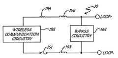
- FIG. 4is a simplified block diagram showing the wireless adapter 30 including a redundant loop current path 164 which is also referred to herein as loop current bypass circuitry.
- Wireless adapter 30includes wireless communication circuitry 155 which is configured for use in transmitting wireless communication signals based upon data communicated with the field device as discussed above.
- Wireless communication circuitry 155is coupled in series with the Loop+ and Loop ⁇ terminals through resistor 156 , an inductor 158 , fuse 161 and inductor 163 .
- Loop current bypass circuitry 164is coupled in parallel with the Loop+ and Loop ⁇ terminals.
- the various componentsare shown as examples only.
- any one of the series componentsshould fail during operation of the wireless adapter and cause an open circuit there will be no current through the wireless adapter.
- the loop current I Lwould normally not be able to flow through the field device 12 and therefore the field device 12 would lose power and not be able to communicate with the control room.
- the loop current I Lwill flow through the bypass circuitry 164 .
- the field device 12will be able to continue operation and function normally even though the wireless communication adapter 30 is no longer operating.
- inductors 158 and 163may be present in the adapter 30 to protect the electronics from noise, electrostatic discharge and transients that may occur on the two-wire process control loop.
- the resistance 156may be present to allow the circuitry to sense the loop current I L or to enable the electronics to operate in an intrinsically safe manner.
- the fuse 161can be provided in order to enable the electronics to be intrinsically safe and disconnect the electronics if there is a short circuit.
- FIG. 5Ais a simplified block diagram of adapter 30 showing one example configuration of loop current bypass circuitry 164 .
- loop current bypass circuitry 164is illustrated as resistors 170 and 172 arranged in parallel with a precision shunt regulator 174 .
- the shunt regulator 174can comprise, for example, a TLVH431 regulator available from Texas Instruments.
- Resistors 170 and 172can be configured to adjust the voltage at which the regulator 174 operates. Typically, this voltage will be selected to be slightly higher (0.25 volts, for instance) than the operating voltage of the wireless communication circuitry 155 . Therefore, when the electronics of adapter 30 are operating normal, shunt 174 will not conduct any current.
- shunt 174will become conducting and carry the loop current I L therethrough.
- the voltage drop across the shunt 174is established by the values of shunt 174 along with resistors 170 and 172 .
- the shunt regulator 174may fail in an open circuit condition. For example, if the loop current is exceptionally high for a temporary period, for example 500 mA, due to a failure or miswiring situation, the shunt regulator 174 may fail in an open condition. When the loop wiring is corrected, the bypass circuitry 164 will remain in the open condition. In order to prevent this from happening, additional circuitry shown in FIG. 5B can be used.
- the bypass circuitry 164includes a transistor 165 .
- the transistor 165can comprise, for example, a PNP transistor, a PNP Darlington transistor, or P-channel enhancement mode MOSFET.
- regulator 174begins conducting current. This will continue until the voltage across resistor 167 exceeds the V be of transistor 165 to thereby cause transistor 165 to conduct current. Once transistor 165 conducts current, it will pass all of the current, except for the bias current flowing through resistors 167 , 170 and 172 and shunt regulator 174 . Thus, the bypass circuitry 164 will be able to pass the amount of current for which transistor 165 is rated.
- Transistor 165may be rated at, for example, 0.5 amps or higher.
- shunt regulator 174may be rated at only about 80 mA. Note that in this configuration the voltage across the Loop+ and Loop ⁇ terminals is still determined by the values of resistors 170 and 172 and the reference voltage of regulator 174 .
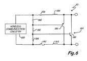
- FIG. 5Bis a simplified schematic diagram of adapter 30 showing another example configuration of the loop current bypass circuitry 164 .
- the loop current bypass circuitry 164includes series resistors 180 , 182 and 184 along with transistors 186 and 188 .
- resistors 180 , 182 and 184are configured to bias transistors 186 and 188 so that both transistors are off in normal operation of the wireless communication adapter 30 .
- resistor 156 or inductor 158becomes an open circuit, then transistor 188 is biased off but transistor 186 is biased on as its base voltage is pulled low. In this configuration, transistor 186 will carry all of the loop current I L thereby enabling the field device 12 to continue normal operations.
- Transistor 186may be biased off, however, transistor 188 will be biased on as its base voltage will be pulled high. Transistor 188 then passes all of the loop current I L enabling normal operation of field device 12 .
- Typical values of resistors 182 and 184may be about one k ⁇ and resistor 180 may be about 47 k ⁇ .
- Transistor 186may be a high gain PNP transistor, a PNP Darlington transistor or a P channel enhancement mode MOSFET transistor.
- Transistor 188may be a high gain NPN transistor, an NPN Darlington transistor, or an N channel enhanced MOSFET transistor.
- One advantage of the configuration shown in FIG. 5Ais the voltage drop of the wireless communications adapter 30 may be lower for this circuitry in comparison to that shown in FIG. 5A .
- FIG. 7is a more detailed block diagram of adapter 30 showing wireless communication circuitry 155 .
- a capacitor 220is illustrated and the adapter 30 is configured for HART® communication as well as wireless communication.
- adapter 30includes a microcontroller 240 which also includes a memory and a modem for communication. The memory is used to store programming instructions, configuration data, variables, etc.
- HART® analog circuitry 242is configured to couple to the field device 12 through a DC blocking capacitor 246 .
- a radio module 244is provided to enable adapter 30 to communicate using RF communication techniques.
- a regulator 248is provided which is configured as a DC to DC converter.
- a current shunt circuit 250is connected in parallel with regulator 248 and includes a bypass transistor 252 controlled by a OP amp 254 .
- OP amp 254operates based upon a difference between a reference voltage (V ref ) and the voltage applied to the regulator 248 .
- Regulator 248provides a 2.3 volt output to a low dropout (LDO) regulator 260 .
- Low dropout (LDO) regulator 260provides a regulated 2 volt power supply output to the microprocessor 240 , HART analog circuits 242 , reset circuit 282 and ADC 280 .
- the current through bypass transistor 252is used to charge the capacitor 220 .
- the voltage across the capacitor 220is set using a voltage clamp 270 .
- the voltage clampcan be set to 2.2 volts.
- Another DC to DC converter 272is configured as a step up converter and provides a regulated voltage output of 3 volts to a low dropout (LDO) regulator 274 .
- the output of low dropout (LDO) regulator 274is set to 2.8 volts and used to provide regulated power to radio module 244 .
- the microprocessor 240is connected to a analog to digital converter 280 which is used to monitor the voltage of capacitor 220 .
- Microprocessor 240is also connected to a reset circuit 282 .
- Microprocessor 240provides data to the radio module 244 through a level shifting circuit 284 .
- the circuitryis able to support the maximum amount of wireless communication activity while dropping a minimum amount of voltage in the loop 22 . Therefore, the adapter 30 is preferably configured to use power from the loop 22 in a very efficient manner. In one specific configuration, this can be achieved by using a low power microcontroller 240 , for example, Atmel ATmega1281 and by using low power analog circuit components. These components can be powered by a low supply voltage to also minimize the total circuit power consumption. Further, the microcontroller 240 can be configured to enter a “sleep” mode if desired when certain functions are not needed, for example communication functions. A separate modem can also be utilized if desired.
- the radio module 244It is also preferable to provide the radio module 244 with a large amount of power. This allows more frequent communication and increased reliability.
- the additional powercan be used to publish information from the transmitter 12 , allow the adapter 30 to be used as a router for other process transmitters, for example in a mesh network and allow higher transmit power to be used. This can result in a more reliable mesh network, as the path from another wireless device through the adapter 30 to a host may be more reliable than the path which is directly from the device to the host.
- the radio module 244is powered by capacitor 220 . Therefore, in order to increase the power which is provided to the radio module 244 , it is preferable to increase the power stored by capacitor 220 . In the configuration of FIG. 7 , this is achieved by arranging the capacitor 220 as a shunt element for the regulator 248 which regulates the voltage drop across the terminals which couple to loop 22 in conjunction with OPamp 254 and shunt transistor 252 . In FIG. 7 , the voltage across the loop terminals which couple to the process control loop 22 is regulated to one volt. This is achieved by adjusting the current going to the capacitor using OPamp 254 and shunt transistor 252 .
- regulator 248operates in series with the loop 22 and is in the feedback loop formed by OPamp 254 .
- a separate one volt shunt regulator and capacitor charging circuitmay be implemented. However, this requires additional components and additional power to operate.
- any loop current which is not used by the circuitry of adapter 30is directed into shunt capacitor 220 for increased efficiency. This results in the maximum amount of power being available for radio module 244 .
- the voltage clamp 270determines the voltage to which capacitor 220 is charged. Once the capacitor 220 reaches the voltage set by the voltage clamp 270 , the excess current flows through clamp 270 rather than into capacitor 220 .
- DC to DC converter 248is configured as a low power “step up” switching regulator that operates with an input voltage of 1 volt. Regulator 248 increases the 1 volt input voltage to a sufficiently high voltage to power the remaining circuitry. In the example of FIG. 7 , this is 2.3 volts.
- the convertercan be a switched capacitor type converter, an inductor based boost converter, a transformer based converter or other appropriate configuration.
- the LDO regulator 260regulates the 2.3 volt output from regulator 248 to 2.0 volts and removes any switching noise from the regulator 248 .
- the output from the LDO regulator 260is used to power the microprocessor 240 , HART® analog circuits 242 , memory, reset circuitry 282 , and analog to digital converter 280 .
- HART® analog circuit block 242can comprise, for example, a carrier detect circuit, a receive circuit and a transmit circuit. Preferably, these circuits are configured to have low power requirements while maintaining acceptable communications integrity.
- the memory in microprocessor 240can be used to store programming code and temporary variables. Timers which are internal to microprocessor 240 can optionally be used to provide a “software” modem functionality.
- the memory of the microprocessor 240may include internal flash memory, RAM as well as EEPROM or other non volatile memory.
- the microcontroller 240can be configured to monitor the voltage access capacitor 220 using analog to digital converter 280 which provides a digital output to microcontroller 240 representative of the capacitive voltage.
- the microcontroller 240can be used to determine whether the capacitor has a sufficient voltage to support radio transmission.
- Reset circuit 282can be used to ensure that microcontroller 240 does not operate when the voltage is insufficient.
- the reset circuit 282can be configured to reset, or turn on, the microcontroller 240 when the supply voltage from LDO regulator 260 reaches a sufficient voltage level.
- the circuitrycan also be used to reset the microcontroller 240 if a power “glitch” occurs.
- Radio module 244operates on a stable voltage of 2.8 volts provided by LDO regulator 274 .
- the DC to DC converter regulator 272steps up the voltage to 3 volts. During use, the voltage on the capacitor will decrease and the step up converter is needed.
- the LDO regulator 274is used to provide a stable 2.8 volts to the radio module 244 .
- regulator 272is configured to operate off a minimum voltage of about 1 volt up to a maximum voltage of about 2.2 volts.
- microcontroller 240is configured to turn off circuitry of radio module 244 if the voltage on the capacitor 220 is less than 1 volt.
- Microcontroller 240can be configured to transmit information wirelessly using the radio module 244 by communicating over digital communication lines between the radio module 244 and the microcontroller 240 .
- the microcontrolleroperates from a two volt power supply while the radio operates from a 2.8 power supply
- the digital communication lines between the two componentsmust be level shifted using level shifting circuitry 284 .
- thiscan be performed using very low power level translator circuits such as Texas Instruments SN74LVC2T45DCU.
- the voltage drop across the loop terminals which couple to loop 22can be adjusted by adjusting V REF coupled to the inverting input of OPamp 254 of the shunt circuitry 250 .
- additional powermay be made available to the radio by increasing the loop voltage drop under appropriate conditions.
- the voltage dropcan be decreased. However, this will provide less power to the radio module and other circuitry of adapter 30 and may degrade performance.
- loop current bypass circuitry 164which is coupled between the Loop+ and the Loop ⁇ connections to process control loop 22 .
- Loop current bypass circuitry 164operates in the manner discussed above. Note that FIG. 7 does not explicitly show resistor 156 , inductors 158 , 163 and fuse 161 illustrated in previous figures. However, these components are located as individual items and not shown in FIG. 7 , or are contained in the various circuit blocks shown in FIG. 7 .
- FIG. 8is a more detailed schematic diagram showing the connections between the wireless adapter and the process control loop 22 .
- the HART terminal and the Loop ⁇ terminal of the adapter 30are coupled to the +Power and ⁇ Power terminals of the field device 12 . Therefore, there is a possibility that a component failure in the adapter 30 may cause a short circuit of the supply voltage provided to the field device 12 . If this occurs, communication of the process variable being measured by the field device will be interrupted and the field device 12 will not be able to communicate to the process control room 20 .
- the circuitry shown in FIG. 8addresses these concerns.
- diodes 300 , 302 and 304are provided for transient protection. They are configured to protect the adapter 30 from high voltage transients that may be induced in the process control loop 22 . These diodes limit the voltage transients to low voltage levels that can be tolerated by the adapter electronics. Diodes 302 and 304 are electrically connected directly across the power terminals of the field device. Note that if only a single transient protection diode was employed, and that diode failed in a short circuit condition, it would short the power provided to the field device 12 . In the configured shown in FIG. 8 , a redundant diode is provided to help prevent such a failure.
- HART analog electronics 242 shown in FIG. 7are illustrated as three separate components, HART transmit circuitry 242 A, HART carrier detect circuitry 242 B and HART receive circuitry 242 C. These circuits operate at a very low DC voltage relative to the Loop ⁇ terminal. If the node shown in FIG. 8 identified as NODE 1 is shorted to the HART terminal due to a component failure, the field device 12 would receive a very low DC voltage across it and would probably not be able to operate correctly. Therefore, redundant capacitors 310 and 312 are provided to connect the HART communications circuits 242 A,B,C to the HART terminal.
- Capacitors 320 , 322 , 324 , 326 , 328 and 330 along with inductors 158 , 163 and 332are used to provide RFI protection to electronics of the adapter 30 . All of these capacitors should have an AC connection to earth ground through the chassis of the adapter 30 in order to create a current path to earth ground for the radio frequency interference. However, in some instances, the process control loop is also connected to earth ground for safety reasons. It is common for a 4-20 mA current loop to be earth grounded at the minus terminal of the power supply 20 A.
- Capacitor 336reduces the possibility of shorting out the power to the field device 12 in the event of a failure of one of the RFI protection capacitors. Note that if capacitor 320 is connected directly to the chassis of the adapter 30 and therefore connected to earth ground, and the capacitor failed in a shorted condition, current would flow from the power source 20 A to the Loop+ terminal of the adapter 30 through the shorted capacitor 320 and to earth ground and then return to the power supply minus connection of power supply 20 A. Thus, there would be no current flow through the adapter electronics or the field device 12 for this component failure.
- the wireless adapter 30has been designed such that no single component failure can cause a failure of the current flow to the field device.
- a redundant bypass circuitprotects the device against the failure of any series component in the electronics of adapter 30 .
- Several redundant componentsare also employed to protect against current flowing around the field device.
- the term “field device” as used hereincan be any device which is used in a process controller monitoring system and does not necessarily require placement in the “field.”
- the devicecan be located anywhere in the process control system including in a control room or control circuitry.
- the terminals used to connect to the process control looprefer to any electrical connection and may not comprise physical or discrete terminals.
- Any appropriate radio frequency communication circuitrycan be used as desired as can any appropriate communication protocol, frequency or communication technique.
- the power supply circuitryis configured as desired and is not limited to the configurations set forth herein.
- the field deviceincludes an address which can be included in any RF transmissions such that the device can be identified. Similarly, such an address can be used to determine if a received signal is intended for that particular device.
- no addressis utilized and data is simply transmitted from the wireless communication circuitry without any addressing information.
- any received datamay not include addressing information. In some embodiments, this may be acceptable.
- other addressing techniques or identification techniquescan be used such as assigning a particular frequency or communication protocol to a particular device, assigning a particular time slot or period to a particular device or other techniques. Any appropriate communication protocol and/or networking technique can be employed including token-based techniques in which a token is handed off between devices to thereby allow transmission or reception for the particular device.
- Radio Frequencycan comprise electromagnetic transmissions of any frequency and is not limited to a particular group of frequencies, range of frequencies or any other limitation.
- Any communication protocolcan be used, as desired, including IEEE 802.11b, 802.15.4, or other protocols, including proprietary communication protocols.
- the wireless adapterprovides a digital signal communication connection for coupling to the two wire process control loop and, in some embodiments, communicating in accordance with the HART® communication protocol.
- the adaptercan be configured to mount externally to a process control transmitter, for example, through a threaded coupling to NPT fittings in the transmitter housing.
Landscapes
- Engineering & Computer Science (AREA)
- Computer Networks & Wireless Communication (AREA)
- Signal Processing (AREA)
- Physics & Mathematics (AREA)
- General Physics & Mathematics (AREA)
- Automation & Control Theory (AREA)
- Arrangements For Transmission Of Measured Signals (AREA)
- Transceivers (AREA)
- Selective Calling Equipment (AREA)
Abstract
Description
The present application is based on and claims the benefit of U.S. provisional patent application Ser. No. 61/073,093, filed Jun. 17, 2008, the content of which is hereby incorporated by reference in its entirety. The present application also notes the following related patent applications: U.S. application Ser. No. 12/125,187, filed May 22, 2008; U.S. Ser. No. 60/997,760, filed Oct. 5, 2007; U.S. Ser. No. 11/842,356, filed Aug. 21, 2007; and U.S. Ser. No. 10/878,235, filed Jun. 28, 2004, now U.S. Pat. No. 7,262,693, the contents of which are hereby incorporated by reference in their entirety.
The present invention relates to industrial process control or monitoring systems. More specifically, the present invention relates to field devices in such systems which are capable of Radio Frequency (RF) communication.
In industrial settings, control systems are used to monitor and control inventories of industrial and chemical processes, and the like. Typically, the control system performs these functions using field devices distributed at key locations in the industrial process and coupled to the control circuitry in the control room by a process control loop. The term “field device” refers to any device that performs a function in a distributed control or process monitoring system, including all devices currently known, or yet to be known, used in the measurement, control and monitoring of industrial processes.
Some field devices include a transducer. A transducer is understood to mean either a device that generates an output signal based on a physical input or that generates a physical output based on an input signal. Typically, a transducer transforms an input into an output having a different form. Types of transducers include various analytical equipment, pressure sensors, thermistors, thermocouples, strain gauges, flow transmitters, positioners, actuators, solenoids, indicator lights, and others.
Typically, each field device also includes communication circuitry that is used for communicating with a process control room, or other circuitry, over a process control loop. In some installations, the process control loop is also used to deliver a regulated current and/or voltage to the field device for powering the field device. The process control loop also carries data, either in an analog or digital format.
Traditionally, analog field devices have been connected to the control room by two-wire process control current loops, with each device connected to the control room by a single two-wire control loop. Typically, a voltage differential is maintained between the two-wires within a range of voltages from 12-45 volts for analog mode and 9-50 volts for digital mode. Some analog field devices transmit a signal to the control room by modulating the current running through the current loop to a current proportional to the sensed process variable. Other analog field devices can perform an action under the control of the control room by controlling the magnitude of the current through the loop. In addition to, or in the alternative, the process control loop can carry digital signals used for communication with field devices.
In some installations, wireless technologies have begun to be used to communicate with field devices. For example, completely wireless installations are used in which the field device uses a battery, solar cell, or other technique to obtain power without any sort of wired connection. However, the majority of field devices are hardwired to a process control room and do not use wireless communication techniques.
Industrial process plants often contain hundreds or even thousands of field devices. Many of these field devices contain sophisticated electronics and are able to provide more data than the traditional analog 4-20 mA measurements. For a number of reasons, cost among them, many plants do not take advantage of the extra data that may be provided by such field devices. This has created a need for a wireless adapter for such field devices that can attach to the field devices and transmit data back to a control system or other monitoring or diagnostic system or application via a wireless network.
In some configurations, an RF adapter can be connected in series with the process control loop. In such a configuration, a loop current of the process control loop flows through circuitry of the wireless adapter. Should the circuitry of the wireless adapter fail, an open circuit may cause the loop current to not have a current path and any field devices coupled to the two-wire process control loop will no longer be able to communicate using the process control loop.
A wireless adapter for use with a two-wire process control loop is configured to couple to a process field device in an industrial process control system. The wireless adapter is coupled to the two-wire process control loop and provides wireless communication to the process field device. The adapter includes first and second loop terminals configured to couple in series with the two-wire process control loop. Wireless communication circuitry is coupled to the first and second loop terminals and is adapted to provide wireless communication to the process field device. Loop current bypass circuitry is electrically connected between the first and second loop terminals and is configured to provide a loop current path therebetween in response to an open circuit in wireless communication circuitry.
The present invention provides a wireless adapter for use with a field device in an industrial process control or monitoring system. The wireless adapter couples to the field device and provides the field device with wireless communication abilities. The adapter also couples to a two-wire process control loop which is used to connect the remotely located field device to a local location such as a process control room or the like. The adapter includes loop current bypass circuitry configured to provide a current path for a loop current of the two-wire process control loop in response to an open circuit condition in a current path of the wireless communication circuitry. This allows the two-wire process control loop to continue to function in the event of a failure of the wireless communication in circuitry in the wireless adapter.
InFIG. 1 , awireless adapter 30 is shown coupled to thefield device 12.Wireless adapter 30 can be used for wireless communications, illustrated byarrows adapter 30 can communicate with ahandheld communicator 40 or anotherfield device 42 which includes awireless adapter 44.Field device 42 is shown coupled to process piping46.
Thewireless adapter 30 can communicate to other devices or components as desired and can be in communication with a remote monitoring or diagnostic system or application. The communication can be in accordance with any appropriate protocol. One example protocol such as wireless HART® includes the formation of a mesh network in which data is passed between wireless devices in order to expand and improve the reliability of the communication system
During operation, theadapter 30 operates using current from the 4-20 mA current flowing through theprocess control loop 22. InFIGS. 3A and 3B , theload resistor 20A is illustrated.Load resistor 20A is used by the process control system to sense the current ILoopflowing through theprocess control loop 22. For example, a process control system can convert a measured voltage across the load resistance to a value which is indicative of the process variable being sensed by a process variable transmitter. This variable may be related, for example, to process pressure, temperature, level, flow, or some other measured parameter. Typically, the load resistance has a value of 250 ohms. When the process control loop is carrying 4 mA, the voltage across this resistor is 1.0 volts. Similarly, when the process control loop is operating in 20 mA, the voltage drop across the resistor is 5 volts.
As illustrated inFIGS. 3A and 3B , the loop current (ILor ILoop) flows through thewireless adapter 30 which is electrically coupled in series with theprocess device 12. If thewireless adapter 30 should fail in a manner which causes an open circuit to occur in theprocess control loop 22, thefield device 12 will lose power and will not be able to communicate with thecontrol room 20.
In the configuration ofFIG. 5A , it is possible for theshunt regulator 174 to fail in an open circuit condition. For example, if the loop current is exceptionally high for a temporary period, for example 500 mA, due to a failure or miswiring situation, theshunt regulator 174 may fail in an open condition. When the loop wiring is corrected, thebypass circuitry 164 will remain in the open condition. In order to prevent this from happening, additional circuitry shown inFIG. 5B can be used. InFIG. 5B , thebypass circuitry 164 includes atransistor 165. Thetransistor 165 can comprise, for example, a PNP transistor, a PNP Darlington transistor, or P-channel enhancement mode MOSFET. Thus, in a high current situation, when, forexample fuse 161 is opened,regulator 174 begins conducting current. This will continue until the voltage acrossresistor 167 exceeds the Vbeoftransistor 165 to thereby causetransistor 165 to conduct current. Oncetransistor 165 conducts current, it will pass all of the current, except for the bias current flowing throughresistors shunt regulator 174. Thus, thebypass circuitry 164 will be able to pass the amount of current for whichtransistor 165 is rated.Transistor 165 may be rated at, for example, 0.5 amps or higher. On the other hand,shunt regulator 174 may be rated at only about 80 mA. Note that in this configuration the voltage across the Loop+ and Loop− terminals is still determined by the values ofresistors regulator 174.
The current throughbypass transistor 252 is used to charge thecapacitor 220. The voltage across thecapacitor 220 is set using avoltage clamp 270. For example, the voltage clamp can be set to 2.2 volts. Another DC to DC converter272 is configured as a step up converter and provides a regulated voltage output of 3 volts to a low dropout (LDO) regulator274. The output of low dropout (LDO) regulator274 is set to 2.8 volts and used to provide regulated power toradio module 244.
Themicroprocessor 240 is connected to a analog todigital converter 280 which is used to monitor the voltage ofcapacitor 220.Microprocessor 240 is also connected to areset circuit 282.Microprocessor 240 provides data to theradio module 244 through alevel shifting circuit 284.
It is preferable that the circuitry is able to support the maximum amount of wireless communication activity while dropping a minimum amount of voltage in theloop 22. Therefore, theadapter 30 is preferably configured to use power from theloop 22 in a very efficient manner. In one specific configuration, this can be achieved by using alow power microcontroller 240, for example, Atmel ATmega1281 and by using low power analog circuit components. These components can be powered by a low supply voltage to also minimize the total circuit power consumption. Further, themicrocontroller 240 can be configured to enter a “sleep” mode if desired when certain functions are not needed, for example communication functions. A separate modem can also be utilized if desired.
It is also preferable to provide theradio module 244 with a large amount of power. This allows more frequent communication and increased reliability. The additional power can be used to publish information from thetransmitter 12, allow theadapter 30 to be used as a router for other process transmitters, for example in a mesh network and allow higher transmit power to be used. This can result in a more reliable mesh network, as the path from another wireless device through theadapter 30 to a host may be more reliable than the path which is directly from the device to the host.
In the embodiment ofFIG. 7 , theradio module 244 is powered bycapacitor 220. Therefore, in order to increase the power which is provided to theradio module 244, it is preferable to increase the power stored bycapacitor 220. In the configuration ofFIG. 7 , this is achieved by arranging thecapacitor 220 as a shunt element for theregulator 248 which regulates the voltage drop across the terminals which couple toloop 22 in conjunction withOPamp 254 andshunt transistor 252. InFIG. 7 , the voltage across the loop terminals which couple to theprocess control loop 22 is regulated to one volt. This is achieved by adjusting the current going to thecapacitor using OPamp 254 andshunt transistor 252. In this configuration,regulator 248 operates in series with theloop 22 and is in the feedback loop formed byOPamp 254. In a less efficient configuration, a separate one volt shunt regulator and capacitor charging circuit may be implemented. However, this requires additional components and additional power to operate. In contrast, in the configuration set forth inFIG. 7 , any loop current which is not used by the circuitry ofadapter 30 is directed intoshunt capacitor 220 for increased efficiency. This results in the maximum amount of power being available forradio module 244. Thevoltage clamp 270 determines the voltage to whichcapacitor 220 is charged. Once thecapacitor 220 reaches the voltage set by thevoltage clamp 270, the excess current flows throughclamp 270 rather than intocapacitor 220.
DC toDC converter 248 is configured as a low power “step up” switching regulator that operates with an input voltage of 1 volt.Regulator 248 increases the 1 volt input voltage to a sufficiently high voltage to power the remaining circuitry. In the example ofFIG. 7 , this is 2.3 volts. The converter can be a switched capacitor type converter, an inductor based boost converter, a transformer based converter or other appropriate configuration. TheLDO regulator 260 regulates the 2.3 volt output fromregulator 248 to 2.0 volts and removes any switching noise from theregulator 248. The output from theLDO regulator 260 is used to power themicroprocessor 240, HART® analog circuits 242, memory, resetcircuitry 282, and analog todigital converter 280.
HART®analog circuit block 242 can comprise, for example, a carrier detect circuit, a receive circuit and a transmit circuit. Preferably, these circuits are configured to have low power requirements while maintaining acceptable communications integrity. The memory inmicroprocessor 240 can be used to store programming code and temporary variables. Timers which are internal tomicroprocessor 240 can optionally be used to provide a “software” modem functionality. The memory of themicroprocessor 240 may include internal flash memory, RAM as well as EEPROM or other non volatile memory. Themicrocontroller 240 can be configured to monitor thevoltage access capacitor 220 using analog todigital converter 280 which provides a digital output tomicrocontroller 240 representative of the capacitive voltage. If desired, themicrocontroller 240 can be used to determine whether the capacitor has a sufficient voltage to support radio transmission.Reset circuit 282 can be used to ensure thatmicrocontroller 240 does not operate when the voltage is insufficient. For example, thereset circuit 282 can be configured to reset, or turn on, themicrocontroller 240 when the supply voltage fromLDO regulator 260 reaches a sufficient voltage level. The circuitry can also be used to reset themicrocontroller 240 if a power “glitch” occurs.
In one configuration, the voltage drop across the loop terminals which couple toloop 22 can be adjusted by adjusting VREFcoupled to the inverting input ofOPamp 254 of theshunt circuitry 250. In such a configuration, additional power may be made available to the radio by increasing the loop voltage drop under appropriate conditions. Similarly, if the impact on the process control loop of the circuitry ofadapter 30 needs to be reduced, the voltage drop can be decreased. However, this will provide less power to the radio module and other circuitry ofadapter 30 and may degrade performance.
Also shown inFIG. 7 is the arrangement of loopcurrent bypass circuitry 164 which is coupled between the Loop+ and the Loop− connections to processcontrol loop 22. Loopcurrent bypass circuitry 164 operates in the manner discussed above. Note thatFIG. 7 does not explicitly showresistor 156,inductors FIG. 7 , or are contained in the various circuit blocks shown inFIG. 7 .
InFIG. 8 ,diodes adapter 30 from high voltage transients that may be induced in theprocess control loop 22. These diodes limit the voltage transients to low voltage levels that can be tolerated by the adapter electronics.Diodes field device 12. In the configured shown inFIG. 8 , a redundant diode is provided to help prevent such a failure.
InFIG. 8 , theHART analog electronics 242 shown inFIG. 7 are illustrated as three separate components, HART transmitcircuitry 242A, HART carrier detectcircuitry 242B and HART receivecircuitry 242C. These circuits operate at a very low DC voltage relative to the Loop− terminal. If the node shown inFIG. 8 identified asNODE 1 is shorted to the HART terminal due to a component failure, thefield device 12 would receive a very low DC voltage across it and would probably not be able to operate correctly. Therefore,redundant capacitors HART communications circuits 242A,B,C to the HART terminal. If one of these capacitors fails in a shorted condition, the voltage provided to thefield device 12 will not be effected and the HART communications circuitry in theadapter 30 will also continue to function correctly.Capacitors inductors adapter 30. All of these capacitors should have an AC connection to earth ground through the chassis of theadapter 30 in order to create a current path to earth ground for the radio frequency interference. However, in some instances, the process control loop is also connected to earth ground for safety reasons. It is common for a 4-20 mA current loop to be earth grounded at the minus terminal of thepower supply 20A. A redundant capacitor to connect the RFI protection capacitors to the chassis of theadapter 30 is also illustrated inFIG. 8 atelement 336.Capacitor 336 reduces the possibility of shorting out the power to thefield device 12 in the event of a failure of one of the RFI protection capacitors. Note that ifcapacitor 320 is connected directly to the chassis of theadapter 30 and therefore connected to earth ground, and the capacitor failed in a shorted condition, current would flow from thepower source 20A to the Loop+ terminal of theadapter 30 through the shortedcapacitor 320 and to earth ground and then return to the power supply minus connection ofpower supply 20A. Thus, there would be no current flow through the adapter electronics or thefield device 12 for this component failure. However, with thecapacitor 336 in place, the flow of DC current through theadapter 30 and thefield device 12 will not be affected by a short ofcapacitor 320. A short ofcapacitor 324 would cause a similar type of failure. A short incapacitors power supply 20A and bypass the field device ifcapacitor 336 was not present. Similarly, withoutcapacitor 336 in place, and if the plus terminal ofpower source 20A is earth grounded, shouldcapacitors power supply 20A through the shortedcapacitor resistor 20B through the HART terminal. Thus, no current would flow through theadapter electronics 30 or thefield device 12 ifcapacitors redundant capacitor 336.
Thus, in the configuration ofFIG. 8 , thewireless adapter 30 has been designed such that no single component failure can cause a failure of the current flow to the field device. A redundant bypass circuit protects the device against the failure of any series component in the electronics ofadapter 30. Several redundant components are also employed to protect against current flowing around the field device.
The term “field device” as used herein can be any device which is used in a process controller monitoring system and does not necessarily require placement in the “field.” The device can be located anywhere in the process control system including in a control room or control circuitry. The terminals used to connect to the process control loop refer to any electrical connection and may not comprise physical or discrete terminals. Any appropriate radio frequency communication circuitry can be used as desired as can any appropriate communication protocol, frequency or communication technique. The power supply circuitry is configured as desired and is not limited to the configurations set forth herein. In some embodiments, the field device includes an address which can be included in any RF transmissions such that the device can be identified. Similarly, such an address can be used to determine if a received signal is intended for that particular device. However, in other embodiments, no address is utilized and data is simply transmitted from the wireless communication circuitry without any addressing information. In such a configuration, if receipt of data is desired, any received data may not include addressing information. In some embodiments, this may be acceptable. In others, other addressing techniques or identification techniques can be used such as assigning a particular frequency or communication protocol to a particular device, assigning a particular time slot or period to a particular device or other techniques. Any appropriate communication protocol and/or networking technique can be employed including token-based techniques in which a token is handed off between devices to thereby allow transmission or reception for the particular device.
Although the present invention has been described with reference to preferred embodiments, workers skilled in the art will recognize that changes may be made in form and detail without departing from the spirit and scope of the invention. As used herein, Radio Frequency (RF) can comprise electromagnetic transmissions of any frequency and is not limited to a particular group of frequencies, range of frequencies or any other limitation. Any communication protocol can be used, as desired, including IEEE 802.11b, 802.15.4, or other protocols, including proprietary communication protocols. In the discussion above, the wireless adapter provides a digital signal communication connection for coupling to the two wire process control loop and, in some embodiments, communicating in accordance with the HART® communication protocol. The adapter can be configured to mount externally to a process control transmitter, for example, through a threaded coupling to NPT fittings in the transmitter housing.
Although the present invention has been described with reference to preferred embodiments, workers skilled in the art will recognize that changes may be made in form and detail without departing from the spirit and scope of the invention.
Claims (22)
1. A wireless adapter for use in a two-wire process control loop configured to couple to a process field device in an industrial process control system which is coupled to the two-wire process control loop and provide wireless communication to the process field device, comprising:
first and second loop terminals configured to couple in series with the two-wire process control loop;
wireless communication circuitry coupled to the first and second loop terminals adapted to provide wireless communication to the process field device; and
loop current bypass circuitry electrically connected between the first and second loop terminals configured to provide a loop current path therebetween in response to an open circuit in a current path of the wireless communication circuitry between the first and second loop terminals.
2. The apparatus ofclaim 1 wherein the loop current bypass circuitry includes a precision shunt regulator.
3. The apparatus ofclaim 2 wherein the precision shunt regulator is configured to conduct electricity, conduct the loop current in response to the open circuit.
4. The apparatus ofclaim 1 wherein the loop current bypass circuitry includes a transistor.
5. The apparatus ofclaim 4 wherein the transistor is configured to conduct the loop current in response to the open circuit.
6. The apparatus ofclaim 4 including a second transistor.
7. The apparatus ofclaim 4 having a base biased whereby the transistor is not conducting when electrical current is flowing through the wireless communication circuitry and biased to be conducting when electrical current is blocked from the wireless communication circuitry.
8. The apparatus ofclaim 4 wherein the transistor comprises a PNP transistor.
9. The apparatus ofclaim 4 wherein the transistor comprises a Darlington transistor.
10. The apparatus ofclaim 4 wherein the transistor comprises a MOSFET.
11. The apparatus ofclaim 4 wherein the transistor comprises an NPN transistor.
12. The apparatus ofclaim 1 including a third connection configured to electrically couple to the field device.
13. The apparatus ofclaim 12 including communication circuitry configured to communicate to the field device through the third connection.
14. The apparatus ofclaim 1 including redundant components to provide power to the field device in the event of a failure of circuitry in the adapter.
15. The apparatus ofclaim 1 wherein the two-wire process control loop comprises a 4-20 mA current loop.
16. The apparatus ofclaim 1 wherein the two-wire process control loop carries digital communication in accordance with the HART® communication protocol.
17. A method of providing wireless communication to a process field device coupled to a two-wire process control loop using a wireless adapter, comprising:
coupling first and second loop terminals of the wireless adapter to the two-wire process control loop;
providing power to wireless communication circuitry from the two-wire process control loop through the first and second loop terminals;
providing wireless communication to the process field device using wireless communication circuitry powered with power received from the two-wire process control loops;
electrically bypassing the wireless communication circuitry by providing a current path between the first and second loop terminals in response to an open circuit in a current path through the wireless communication circuitry.
18. The method ofclaim 17 wherein electrically bypassing includes activating a precision shunt regulator.
19. The method ofclaim 17 wherein electrically bypassing includes activating a transistor.
20. The method ofclaim 17 including communicating with the field device through the third connection.
21. The method ofclaim 17 wherein the two-wire process control loop carries digital communication in accordance with the HART® communication protocol.
22. The method ofclaim 17 wherein one of the first and second loop terminals directly couples to the process field device and further including coupling a communication terminal to the process field device for use in communicating with the process field device.
Priority Applications (1)
| Application Number | Priority Date | Filing Date | Title |
|---|---|---|---|
| US12/486,253US8049361B2 (en) | 2008-06-17 | 2009-06-17 | RF adapter for field device with loop current bypass |
Applications Claiming Priority (2)
| Application Number | Priority Date | Filing Date | Title |
|---|---|---|---|
| US7309308P | 2008-06-17 | 2008-06-17 | |
| US12/486,253US8049361B2 (en) | 2008-06-17 | 2009-06-17 | RF adapter for field device with loop current bypass |
Publications (2)
| Publication Number | Publication Date |
|---|---|
| US20090311971A1 US20090311971A1 (en) | 2009-12-17 |
| US8049361B2true US8049361B2 (en) | 2011-11-01 |
Family
ID=41066655
Family Applications (1)
| Application Number | Title | Priority Date | Filing Date |
|---|---|---|---|
| US12/486,253Active2030-01-14US8049361B2 (en) | 2008-06-17 | 2009-06-17 | RF adapter for field device with loop current bypass |
Country Status (6)
| Country | Link |
|---|---|
| US (1) | US8049361B2 (en) |
| EP (1) | EP2294765B1 (en) |
| JP (1) | JP5232299B2 (en) |
| CN (1) | CN102084626B (en) |
| CA (1) | CA2726534C (en) |
| WO (1) | WO2009154749A1 (en) |
Cited By (9)
| Publication number | Priority date | Publication date | Assignee | Title |
|---|---|---|---|---|
| US20130092854A1 (en)* | 2011-10-14 | 2013-04-18 | Azbil Corporation | Positioner |
| US20160299175A1 (en)* | 2015-04-09 | 2016-10-13 | Fisher-Rosemount Systems, Inc. | Method for Supplying Fieldbus Communication and Power from a Handheld Maintenance Tool in a Hazardous Area Using a Single Lead Set |
| US9615149B1 (en) | 2015-10-26 | 2017-04-04 | Honeywell International Inc. | Process interface including wireless multi-loop single hop device |
| US9953474B2 (en) | 2016-09-02 | 2018-04-24 | Honeywell International Inc. | Multi-level security mechanism for accessing a panel |
| US10684030B2 (en) | 2015-03-05 | 2020-06-16 | Honeywell International Inc. | Wireless actuator service |
| US10789800B1 (en) | 2019-05-24 | 2020-09-29 | Ademco Inc. | Systems and methods for authorizing transmission of commands and signals to an access control device or a control panel device |
| US10832509B1 (en) | 2019-05-24 | 2020-11-10 | Ademco Inc. | Systems and methods of a doorbell device initiating a state change of an access control device and/or a control panel responsive to two-factor authentication |
| US11513018B2 (en)* | 2020-09-30 | 2022-11-29 | Rosemount Inc. | Field device housing assembly |
| US12218775B2 (en) | 2022-12-19 | 2025-02-04 | Rosemount Inc. | Advanced physical layer (APL) adapter for legacy field devices |
Families Citing this family (17)
| Publication number | Priority date | Publication date | Assignee | Title |
|---|---|---|---|---|
| WO2009154748A2 (en) | 2008-06-17 | 2009-12-23 | Rosemount Inc. | Rf adapter for field device with low voltage intrinsic safety clamping |
| US8929948B2 (en) | 2008-06-17 | 2015-01-06 | Rosemount Inc. | Wireless communication adapter for field devices |
| CN102084626B (en) | 2008-06-17 | 2013-09-18 | 罗斯蒙德公司 | RF adapter for field device with loop current bypass |
| CN102067048B (en) | 2008-06-17 | 2017-03-08 | 罗斯蒙特公司 | For having the RF adapter of the field apparatus of variable-pressure drop |
| EP2370868B1 (en)* | 2008-12-05 | 2020-04-01 | Fisher Controls International Llc | Method and apparatus for operating field devices via a portable communicator |
| US8331273B2 (en)* | 2009-08-28 | 2012-12-11 | Mediatek Inc. | Communication methods employed in communication system associated with programmable communication protocols, and related transmitting methods, receiving methods and communication device |
| US10761524B2 (en)* | 2010-08-12 | 2020-09-01 | Rosemount Inc. | Wireless adapter with process diagnostics |
| US9264787B2 (en)* | 2010-11-29 | 2016-02-16 | Rosemount Inc. | Communication system for process field device |
| US9080683B2 (en)* | 2011-02-17 | 2015-07-14 | Fisher Controls International Llc | Method and apparatus for partial stroke testing of an emergency shutdown valve |
| US8626916B2 (en)* | 2011-07-20 | 2014-01-07 | Fisher-Rosemount Systems, Inc. | Handheld field maintenance tool with process communication tunnel |
| US9310794B2 (en) | 2011-10-27 | 2016-04-12 | Rosemount Inc. | Power supply for industrial process field device |
| WO2015147688A1 (en)* | 2014-03-28 | 2015-10-01 | Rosemount Inc. | Process variable transmitter with loop-powered wireless transceiver |
| DE202014105981U1 (en)* | 2014-12-11 | 2015-02-27 | Endress + Hauser Gmbh + Co. Kg | Field indicator with remote display |
| US11004637B2 (en)* | 2018-03-22 | 2021-05-11 | Rosemount Inc. | Field device latching relay reset |
| US10749256B1 (en)* | 2019-01-30 | 2020-08-18 | Raytheon Company | Waveguide adapter for slot antennas |
| CN110401642A (en)* | 2019-07-10 | 2019-11-01 | 浙江中烟工业有限责任公司 | A method for collecting and analyzing industrial control traffic |
| DE102020105605A1 (en)* | 2020-03-03 | 2021-09-09 | Endress+Hauser SE+Co. KG | Field device adapter for wireless data transmission |
Citations (255)
| Publication number | Priority date | Publication date | Assignee | Title |
|---|---|---|---|---|
| US2533339A (en) | 1946-06-22 | 1950-12-12 | Jabez Burns & Sons Inc | Flammable vapor protection |
| US2883489A (en) | 1954-12-06 | 1959-04-21 | Daystrom Inc | Encased electrical instrument |
| US3012432A (en) | 1957-09-23 | 1961-12-12 | Richard H Moore | Leak tester |
| US3218863A (en) | 1962-05-07 | 1965-11-23 | Wayne Kerr Lab Ltd | Pressure responsive apparatus |
| US3232712A (en) | 1962-08-16 | 1966-02-01 | Continental Lab Inc | Gas detector and analyzer |
| US3249833A (en) | 1964-11-16 | 1966-05-03 | Robert E Vosteen | Capacitor transducer |
| US3374112A (en) | 1964-03-05 | 1968-03-19 | Yeda Res & Dev | Method and apparatus for controlled deposition of a thin conductive layer |
| US3557621A (en) | 1969-07-07 | 1971-01-26 | C G S Scient Corp Inc | Variable capacitance detecting devices |
| US3612851A (en) | 1970-04-17 | 1971-10-12 | Lewis Eng Co | Rotatably adjustable indicator instrument |
| US3697835A (en) | 1970-05-25 | 1972-10-10 | Medicor Muevek | Capacitive pressure transducer |
| US3742450A (en) | 1971-05-12 | 1973-06-26 | Bell Telephone Labor Inc | Isolating power supply for communication loop |
| US3808480A (en) | 1973-04-16 | 1974-04-30 | Bunker Ramo | Capacitive pressure transducer |
| GB1397435A (en) | 1972-08-25 | 1975-06-11 | Hull F R | Regenerative vapour power plant |
| US3924219A (en) | 1971-12-22 | 1975-12-02 | Minnesota Mining & Mfg | Gas detection device |
| US4008619A (en) | 1975-11-17 | 1977-02-22 | Mks Instruments, Inc. | Vacuum monitoring |
| US4063349A (en) | 1976-12-02 | 1977-12-20 | Honeywell Information Systems Inc. | Method of protecting micropackages from their environment |
| DE2710211A1 (en) | 1977-03-09 | 1978-09-14 | Licentia Gmbh | Electronic control circuits cast in silicone rubber or epoxy! resin - have accessible components e.g. terminals protected by removable silicone rubber hoods prior to casting |
| US4158217A (en) | 1976-12-02 | 1979-06-12 | Kaylico Corporation | Capacitive pressure transducer with improved electrode |
| US4168518A (en) | 1977-05-10 | 1979-09-18 | Lee Shih Y | Capacitor transducer |
| US4177496A (en) | 1976-03-12 | 1979-12-04 | Kavlico Corporation | Capacitive pressure transducer |
| US4227419A (en) | 1979-09-04 | 1980-10-14 | Kavlico Corporation | Capacitive pressure transducer |
| US4287553A (en) | 1980-06-06 | 1981-09-01 | The Bendix Corporation | Capacitive pressure transducer |
| US4322775A (en) | 1979-10-29 | 1982-03-30 | Delatorre Leroy C | Capacitive pressure sensor |
| US4336567A (en) | 1980-06-30 | 1982-06-22 | The Bendix Corporation | Differential pressure transducer |
| US4358814A (en) | 1980-10-27 | 1982-11-09 | Setra Systems, Inc. | Capacitive pressure sensor |
| US4370890A (en) | 1980-10-06 | 1983-02-01 | Rosemount Inc. | Capacitive pressure transducer with isolated sensing diaphragm |
| US4383801A (en) | 1981-03-02 | 1983-05-17 | Pryor Dale H | Wind turbine with adjustable air foils |
| US4389895A (en) | 1981-07-27 | 1983-06-28 | Rosemount Inc. | Capacitance pressure sensor |
| US4422125A (en) | 1982-05-21 | 1983-12-20 | The Bendix Corporation | Pressure transducer with an invariable reference capacitor |
| US4422335A (en) | 1981-03-25 | 1983-12-27 | The Bendix Corporation | Pressure transducer |
| US4434451A (en) | 1979-10-29 | 1984-02-28 | Delatorre Leroy C | Pressure sensors |
| US4455874A (en) | 1981-12-28 | 1984-06-26 | Paroscientific, Inc. | Digital pressure transducer |
| US4458537A (en) | 1981-05-11 | 1984-07-10 | Combustion Engineering, Inc. | High accuracy differential pressure capacitive transducer |
| US4475047A (en) | 1982-04-29 | 1984-10-02 | At&T Bell Laboratories | Uninterruptible power supplies |
| US4476853A (en) | 1982-09-28 | 1984-10-16 | Arbogast Clayton C | Solar energy recovery system |
| US4490773A (en) | 1983-12-19 | 1984-12-25 | United Technologies Corporation | Capacitive pressure transducer |
| US4510400A (en) | 1982-08-12 | 1985-04-09 | Zenith Electronics Corporation | Switching regulator power supply |
| DE3340834A1 (en) | 1983-11-11 | 1985-05-23 | Philips Patentverwaltung Gmbh, 2000 Hamburg | Circuit arrangement for keeping the temperature-dependent sensitivity of a differential-pressure measurement apparatus constant |
| US4542436A (en) | 1984-04-10 | 1985-09-17 | Johnson Service Company | Linearized capacitive pressure transducer |
| US4562742A (en) | 1984-08-07 | 1986-01-07 | Bell Microcomponents, Inc. | Capacitive pressure transducer |
| US4570217A (en) | 1982-03-29 | 1986-02-11 | Allen Bruce S | Man machine interface |
| US4590466A (en) | 1982-06-28 | 1986-05-20 | Pharos Ab | Method and apparatus for sampling measurement data from a chemical process |
| US4670733A (en) | 1985-07-01 | 1987-06-02 | Bell Microsensors, Inc. | Differential pressure transducer |
| US4701938A (en) | 1984-11-03 | 1987-10-20 | Keystone International, Inc. | Data system |
| US4704607A (en) | 1984-10-25 | 1987-11-03 | Sieger Limited | System for remotely adjusting a parameter of an electrical circuit within an enclosure |
| US4749993A (en) | 1985-02-01 | 1988-06-07 | Dr. Ing. H.C.F. Porsche Aktiengesellschaft | Arrangement for the wireless transmission of measuring signals |
| DE3711754A1 (en) | 1987-04-07 | 1988-10-27 | Heinrichs Messgeraete Josef | Explosion-proof magneto-inductive flow meter |
| US4785669A (en) | 1987-05-18 | 1988-11-22 | Mks Instruments, Inc. | Absolute capacitance manometers |
| US4860232A (en) | 1987-04-22 | 1989-08-22 | Massachusetts Institute Of Technology | Digital technique for precise measurement of variable capacitance |
| US4875369A (en) | 1987-09-08 | 1989-10-24 | Panex Corporation | Pressure sensor system |
| US4878012A (en) | 1988-06-10 | 1989-10-31 | Rosemount Inc. | Charge balanced feedback transmitter |
| CH672368A5 (en) | 1987-08-20 | 1989-11-15 | Rudolf Staempfli | Solar thermal power plant with expansive heat engine - utilises pressure increase of working fluid in thermal storage heater transmitting energy between two closed circuits |
| US4926674A (en) | 1988-11-03 | 1990-05-22 | Innovex Inc. | Self-zeroing pressure signal generator |
| DE3842379A1 (en) | 1988-12-16 | 1990-06-21 | Heinrichs Messgeraete Josef | Electromagnetic arrangement in a measuring instrument of explosion-protected design |
| US4951174A (en) | 1988-12-30 | 1990-08-21 | United Technologies Corporation | Capacitive pressure sensor with third encircling plate |
| US4977480A (en) | 1988-09-14 | 1990-12-11 | Fuji Koki Mfg. Co., Ltd. | Variable-capacitance type sensor and variable-capacitance type sensor system using the same |
| US4982412A (en) | 1989-03-13 | 1991-01-01 | Moore Push-Pin Company | Apparatus and method for counting a plurality of similar articles |
| US5009311A (en) | 1990-06-11 | 1991-04-23 | Schenk Robert J | Removable rigid support structure for circuit cards |
| US5014176A (en) | 1989-02-21 | 1991-05-07 | Raytheon Company | Switching converter with spike limiting circuit |
| US5023746A (en) | 1988-12-05 | 1991-06-11 | Epstein Barry M | Suppression of transients by current sharing |
| US5025202A (en) | 1989-09-08 | 1991-06-18 | Mitsubishi Denki Kabushiki Kaisha | Solar cell power system with a solar array bus lockup cancelling mechanism |
| US5045963A (en) | 1985-11-28 | 1991-09-03 | Danfoss A/S | Protective circuit for the induction coil of a magnetically inductive flow meter |
| US5060295A (en) | 1985-11-15 | 1991-10-22 | Motorola, Inc. | Radio device with controlled port and method of port control |
| US5094109A (en) | 1990-12-06 | 1992-03-10 | Rosemount Inc. | Pressure transmitter with stress isolation depression |
| USD331370S (en) | 1990-11-15 | 1992-12-01 | Titan Industries, Inc. | Programmable additive controller |
| US5168419A (en) | 1991-07-16 | 1992-12-01 | Panex Corporation | Capacitor and pressure transducer |
| EP0524550A1 (en) | 1991-07-25 | 1993-01-27 | Fibronix Sensoren GmbH | Gas filled relative pressure sensor |
| US5194819A (en) | 1990-08-10 | 1993-03-16 | Setra Systems, Inc. | Linearized capacitance sensor system |
| US5230250A (en) | 1991-09-03 | 1993-07-27 | Delatorre Leroy C | Capacitor and pressure transducer |
| US5233875A (en) | 1992-05-04 | 1993-08-10 | Kavlico Corporation | Stable capacitive pressure transducer system |
| USD345107S (en) | 1992-06-01 | 1994-03-15 | Titan Industries, Inc. | Programmable additive controller |
| US5329818A (en) | 1992-05-28 | 1994-07-19 | Rosemount Inc. | Correction of a pressure indication in a pressure transducer due to variations of an environmental condition |
| US5492016A (en) | 1992-06-15 | 1996-02-20 | Industrial Sensors, Inc. | Capacitive melt pressure measurement with center-mounted electrode post |
| US5495769A (en) | 1993-09-07 | 1996-03-05 | Rosemount Inc. | Multivariable transmitter |
| US5506757A (en) | 1993-06-14 | 1996-04-09 | Macsema, Inc. | Compact electronic data module with nonvolatile memory |
| US5542300A (en) | 1994-01-24 | 1996-08-06 | Setra Systems, Inc. | Low cost, center-mounted capacitive pressure sensor |
| US5546804A (en) | 1994-08-11 | 1996-08-20 | Rosemount Inc. | Transmitter with moisture draining housing and improved method of mounting RFI filters |
| US5554809A (en) | 1993-10-08 | 1996-09-10 | Hitachi, Ltd. | Process detection apparatus |
| GB2300265A (en) | 1995-04-26 | 1996-10-30 | Flotec Uk Ltd | Flowmeter |
| US5606513A (en) | 1993-09-20 | 1997-02-25 | Rosemount Inc. | Transmitter having input for receiving a process variable from a remote sensor |
| US5610552A (en) | 1995-07-28 | 1997-03-11 | Rosemount, Inc. | Isolation circuitry for transmitter electronics in process control system |
| US5637802A (en) | 1995-02-28 | 1997-06-10 | Rosemount Inc. | Capacitive pressure sensor for a pressure transmitted where electric field emanates substantially from back sides of plates |
| US5642301A (en) | 1994-01-25 | 1997-06-24 | Rosemount Inc. | Transmitter with improved compensation |
| EP0518916B1 (en) | 1990-02-21 | 1997-07-30 | Rosemount Inc. | Multifunction isolation transformer |
| US5656782A (en) | 1994-12-06 | 1997-08-12 | The Foxboro Company | Pressure sealed housing apparatus and methods |
| US5665899A (en) | 1996-02-23 | 1997-09-09 | Rosemount Inc. | Pressure sensor diagnostics in a process transmitter |
| US5672832A (en) | 1996-02-15 | 1997-09-30 | Nt International, Inc. | Chemically inert flow meter within caustic fluids having non-contaminating body |
| US5682476A (en) | 1994-10-24 | 1997-10-28 | Fisher-Rosemount Systems, Inc. | Distributed control system having central control providing operating power to wireless transceiver connected to industrial process control field device which providing redundant wireless access |
| DE19622295A1 (en) | 1996-05-22 | 1997-11-27 | Hartmann & Braun Ag | Arrangement for data transmission in process control systems |
| US5705978A (en) | 1995-09-29 | 1998-01-06 | Rosemount Inc. | Process control transmitter |
| US5710552A (en) | 1994-09-30 | 1998-01-20 | Rosemount Inc. | Barrier device |
| US5757608A (en) | 1996-01-25 | 1998-05-26 | Alliedsignal Inc. | Compensated pressure transducer |
| US5787120A (en) | 1995-01-30 | 1998-07-28 | Alcatel N.V. | Transmission method and transmitter for signals with a decoupled low level and at least one coupled high level for a telecommunication network including such a transmitter |
| US5793963A (en) | 1994-10-24 | 1998-08-11 | Fisher Rosemount Systems, Inc. | Apparatus for providing non-redundant secondary access to field devices in a distributed control system |
| US5851083A (en) | 1996-10-04 | 1998-12-22 | Rosemount Inc. | Microwave level gauge having an adapter with a thermal barrier |
| EP0895209A1 (en) | 1997-07-21 | 1999-02-03 | Emerson Electric Co. | Improved power management circuit |
| US5872494A (en) | 1997-06-27 | 1999-02-16 | Rosemount Inc. | Level gage waveguide process seal having wavelength-based dimensions |
| US5911162A (en) | 1997-06-20 | 1999-06-08 | Mks Instruments, Inc. | Capacitive pressure transducer with improved electrode support |
| RU2131934C1 (en) | 1997-09-01 | 1999-06-20 | Санков Олег Николаевич | Installation for heat treatment of materials |
| US5954526A (en) | 1996-10-04 | 1999-09-21 | Rosemount Inc. | Process control transmitter with electrical feedthrough assembly |
| US5978658A (en) | 1995-10-31 | 1999-11-02 | Mitsubishi Denki Kabushiki Kaisha | Portable analog communication device with selectable voice and data filters |
| US5992240A (en) | 1995-11-21 | 1999-11-30 | Fuji Electric Co., Ltd. | Pressure detecting apparatus for measuring pressure based on detected capacitance |
| US6038927A (en) | 1994-08-22 | 2000-03-21 | The Foxboro Company | Vertically mounted differential pressure transmitter having an integrally mounted sensor |
| US6062095A (en) | 1997-06-09 | 2000-05-16 | Magnetrol International | Dual compartment instrument housing |
| US6127739A (en) | 1999-03-22 | 2000-10-03 | Appa; Kari | Jet assisted counter rotating wind turbine |
| JP2000304148A (en) | 1999-04-19 | 2000-11-02 | Yokogawa Electric Corp | Valve positioner and electropneumatic converter |
| US6150798A (en) | 1997-09-18 | 2000-11-21 | Stmicroelectronics S.A. | Voltage regulator |
| USD439181S1 (en) | 2000-03-21 | 2001-03-20 | Rosemount Inc. | Pressure transmitter with dual inlet base and dual compartment housing |
| USD439179S1 (en) | 2000-03-21 | 2001-03-20 | Rosemount Inc. | Pressure transmitter with single inlet base and dual compartment housing |
| USD439180S1 (en) | 2000-03-21 | 2001-03-20 | Rosemount Inc. | Pressure transmitter with single inlet base and single compartment housing |
| USD439178S1 (en) | 2000-03-21 | 2001-03-20 | Rosemount Inc. | Pressure transmitter with dual inlet base and single compartment housing |
| USD439177S1 (en) | 2000-03-21 | 2001-03-20 | Rosemount Inc. | Pressure transmitter with single inlet base and economy housing |
| USD441672S1 (en) | 2000-03-21 | 2001-05-08 | Rosemount Inc. | Pressure transmitter with dual inlet base and economy housing |
| US6236096B1 (en) | 1998-10-06 | 2001-05-22 | National Science Council Of Republic Of China | Structure of a three-electrode capacitive pressure sensor |
| DE20107112U1 (en) | 2001-04-25 | 2001-07-05 | Abb Patent Gmbh, 68309 Mannheim | Device for supplying energy to field devices |
| US6282247B1 (en) | 1997-09-12 | 2001-08-28 | Ericsson Inc. | Method and apparatus for digital compensation of radio distortion over a wide range of temperatures |
| US20010025349A1 (en) | 2000-01-07 | 2001-09-27 | Sharood John N. | Retrofit monitoring device |
| US6295875B1 (en) | 1999-05-14 | 2001-10-02 | Rosemount Inc. | Process pressure measurement devices with improved error compensation |
| DE10104582A1 (en) | 2000-04-17 | 2001-10-25 | Voest Alpine Ind Anlagen | Acquiring measurement data in metal or ceramic works involves transmitting information by radio signals from sensor to scanning unit and back if appropriate |
| US6338283B1 (en) | 1996-09-02 | 2002-01-15 | Vincente Blazquez Navarro | Self-contained electronic system for monitoring purgers, valves and installations in real time |
| US20020011115A1 (en) | 1999-05-14 | 2002-01-31 | Frick Roger L. | Process sensor module having a single ungrounded input/output conductor |
| US20020029130A1 (en) | 1996-03-28 | 2002-03-07 | Evren Eryurek | Flow diagnostic system |
| US6360277B1 (en) | 1998-07-22 | 2002-03-19 | Crydom Corporation | Addressable intelligent relay |
| US6366436B1 (en) | 1998-03-17 | 2002-04-02 | Endress + Hauser Gmbh + Co. | Electronic device for use in regions subject to explosion hazards |
| EP1202145A1 (en) | 2000-10-27 | 2002-05-02 | Foxboro Corporation | Field device with a transmitter and/ or receiver for wireless data communication |
| US6385972B1 (en) | 1999-08-30 | 2002-05-14 | Oscar Lee Fellows | Thermoacoustic resonator |
| US6405139B1 (en) | 1998-09-15 | 2002-06-11 | Bently Nevada Corporation | System for monitoring plant assets including machinery |
| US20020082799A1 (en) | 1999-07-02 | 2002-06-27 | Siemens Ag | Measuring transducer with a corrected output signal |
| US20020095520A1 (en) | 2001-01-12 | 2002-07-18 | Prof. Vector Informatik Gmbh | Methods and devices for the relevancy testing of an identifier |
| US20020097031A1 (en) | 2001-01-23 | 2002-07-25 | Cook Warren E. | Variable power control for process control instruments |
| US6429786B1 (en) | 1996-12-20 | 2002-08-06 | Pepperl + Fuchs Gmbh | Sensor and evaluation system, in particular for double sensors for determining positions and limit values |
| US20020105968A1 (en) | 2001-02-08 | 2002-08-08 | Pruzan Brian M. | System and method for managing wireless vehicular communications |
| US6441747B1 (en) | 2000-04-18 | 2002-08-27 | Motorola, Inc. | Wireless system protocol for telemetry monitoring |
| US6457367B1 (en) | 1999-09-28 | 2002-10-01 | Rosemount Inc. | Scalable process transmitter |
| US20020163323A1 (en) | 2001-03-09 | 2002-11-07 | National Inst. Of Advanced Ind. Science And Tech. | Maximum power point tracking method and device |
| US6487912B1 (en) | 1999-09-28 | 2002-12-03 | Rosemount Inc. | Preinstallation of a pressure sensor module |
| US6504489B1 (en) | 2000-05-15 | 2003-01-07 | Rosemount Inc. | Process control transmitter having an externally accessible DC circuit common |
| US6511337B1 (en) | 1999-09-28 | 2003-01-28 | Rosemount Inc. | Environmentally sealed instrument loop adapter |
| US6510740B1 (en) | 1999-09-28 | 2003-01-28 | Rosemount Inc. | Thermal management in a pressure transmitter |
| JP2003051894A (en) | 2001-08-08 | 2003-02-21 | Mitsubishi Electric Corp | Plant work management system |
| JP2003070079A (en) | 2001-08-29 | 2003-03-07 | Yokogawa Electric Corp | Communications system |
| USD471829S1 (en) | 2001-10-11 | 2003-03-18 | Rosemount Inc. | Dual inlet base pressure instrument |
| EP1293853A1 (en) | 2001-09-12 | 2003-03-19 | ENDRESS + HAUSER WETZER GmbH + Co. KG | Transceiver module for a field device |
| USD472831S1 (en) | 2001-10-11 | 2003-04-08 | Rosemount Inc. | Single inlet base pressure instrument |
| US6546805B2 (en) | 2000-03-07 | 2003-04-15 | Rosemount Inc. | Process fluid transmitter with an environmentally sealed service block |
| US6553076B1 (en) | 1999-03-15 | 2003-04-22 | Actpro International Limited | Mixed mode transceiver digital control network and collision-free communication method |
| US20030083038A1 (en) | 2001-11-01 | 2003-05-01 | Poon King L. | Signal adapter |
| US20030079553A1 (en) | 2001-11-01 | 2003-05-01 | Cain Russell P. | Techniques for monitoring health of vessels containing fluids |
| JP2003134261A (en) | 2001-10-29 | 2003-05-09 | Yokogawa Electric Corp | Field device and communication system using the field device |
| US6571132B1 (en) | 1999-09-28 | 2003-05-27 | Rosemount Inc. | Component type adaptation in a transducer assembly |
| US6574515B1 (en) | 2000-05-12 | 2003-06-03 | Rosemount Inc. | Two-wire field-mounted process device |
| US20030143958A1 (en) | 2002-01-25 | 2003-07-31 | Elias J. Michael | Integrated power and cooling architecture |
| US20030171827A1 (en) | 2002-03-06 | 2003-09-11 | Keyes Marion A. | Appendable system and devices for data acquisition, analysis and control |
| US20030204371A1 (en) | 2002-04-30 | 2003-10-30 | Chevron U.S.A. Inc. | Temporary wireless sensor network system |
| US6662662B1 (en) | 2000-05-04 | 2003-12-16 | Rosemount, Inc. | Pressure transmitter with improved isolator system |
| DE10041160B4 (en) | 2000-08-21 | 2004-01-15 | Abb Research Ltd. | container station |
| US6680690B1 (en) | 2003-02-28 | 2004-01-20 | Saab Marine Electronics Ab | Power efficiency circuit |
| JP2004021877A (en) | 2002-06-20 | 2004-01-22 | Yokogawa Electric Corp | Field equipment |
| US20040086021A1 (en) | 2002-11-01 | 2004-05-06 | Litwin Robert Zachary | Infrared temperature sensors for solar panel |
| JP2004146254A (en) | 2002-10-25 | 2004-05-20 | Yazaki Corp | Method of manufacturing wire harness and method of stopping water |
| US6747573B1 (en) | 1997-02-12 | 2004-06-08 | Enocean Gmbh | Apparatus and method for generating coded high-frequency signals |
| US20040124854A1 (en) | 2002-09-30 | 2004-07-01 | Slezak Marian Jozef Walter | Power management mechanism for loop powered time of flight and level measurement systems |
| US6765968B1 (en) | 1999-09-28 | 2004-07-20 | Rosemount Inc. | Process transmitter with local databus |
| US20040142733A1 (en) | 1997-05-09 | 2004-07-22 | Parise Ronald J. | Remote power recharge for electronic equipment |
| US6771560B2 (en) | 2002-05-31 | 2004-08-03 | Siemens Milltronics Process Instruments Inc. | Method and apparatus for on-board calibration in pulse-echo acoustic ranging system |
| US6774814B2 (en) | 2001-06-22 | 2004-08-10 | Network Technologies Group, Llc | Pipe-to-soil testing apparatus and methods |
| US6778100B2 (en) | 2002-03-06 | 2004-08-17 | Automatika, Inc. | Conduit network system |
| US6792259B1 (en) | 1997-05-09 | 2004-09-14 | Ronald J. Parise | Remote power communication system and method thereof |
| US20040184517A1 (en) | 2002-09-06 | 2004-09-23 | Rosemount Inc. | Two wire transmitter with isolated can output |
| US20040183550A1 (en) | 2002-08-13 | 2004-09-23 | Josef Fehrenbach | System for manufacturing a modularly structured apparatus for determining a physical process quantity, and standardized components |
| US20040199681A1 (en) | 2003-04-04 | 2004-10-07 | Hedtke Robert C. | Transmitter with dual protocol interface |
| US20040203434A1 (en) | 2002-10-23 | 2004-10-14 | Rosemount, Inc. | Virtual wireless transmitter |
| US20040214543A1 (en) | 2003-04-28 | 2004-10-28 | Yasuo Osone | Variable capacitor system, microswitch and transmitter-receiver |
| US20040211456A1 (en) | 2002-07-05 | 2004-10-28 | Brown Jacob E. | Apparatus, system, and method of diagnosing individual photovoltaic cells |
| US20040218326A1 (en) | 2003-04-30 | 2004-11-04 | Joachim Duren | Intrinsically safe field maintenance tool with power islands |
| JP2004317593A (en) | 2003-04-11 | 2004-11-11 | Kyocera Mita Corp | Image forming apparatus |
| US6823072B1 (en) | 1997-12-08 | 2004-11-23 | Thomson Licensing S.A. | Peak to peak signal detector for audio system |
| US20040242169A1 (en) | 2001-05-22 | 2004-12-02 | Andre Albsmeier | Thermally feedable transmitter and sensor system |
| US20040259533A1 (en) | 2003-06-18 | 2004-12-23 | Mark Nixon | Self-configuring communication networks for use with process control systems |
| US6839546B2 (en) | 2002-04-22 | 2005-01-04 | Rosemount Inc. | Process transmitter with wireless communication link |
| US6839790B2 (en) | 2002-06-21 | 2005-01-04 | Smar Research Corporation | Plug and play reconfigurable USB interface for industrial fieldbus network access |
| US20050017602A1 (en) | 2003-03-05 | 2005-01-27 | Arms Steven W. | Shaft mounted energy harvesting for wireless sensor operation and data transmission |
| US20050023858A1 (en) | 1999-03-24 | 2005-02-03 | Donnelly Corporation, A Corporation Of The State Of Michigan | Safety system for a closed compartment of a vehicle |
| US20050029236A1 (en) | 2002-08-05 | 2005-02-10 | Richard Gambino | System and method for manufacturing embedded conformal electronics |
| US20050040570A1 (en) | 2002-01-18 | 2005-02-24 | Andreas Asselborn | Method and device for determining the characteristics of molten metal |
| US20050046595A1 (en) | 2003-08-26 | 2005-03-03 | Mr.John Blyth | Solar powered sign annunciator |
| US20050056106A1 (en) | 1999-09-28 | 2005-03-17 | Nelson Scott D. | Display for process transmitter |
| US20050072239A1 (en) | 2003-09-30 | 2005-04-07 | Longsdorf Randy J. | Process device with vibration based diagnostics |
| US6891838B1 (en) | 1998-06-22 | 2005-05-10 | Statsignal Ipc, Llc | System and method for monitoring and controlling residential devices |
| US20050109395A1 (en) | 2003-11-25 | 2005-05-26 | Seberger Steven G. | Shut down apparatus and method for use with electro-pneumatic controllers |
| US20050118468A1 (en) | 2003-12-01 | 2005-06-02 | Paul Adams | Fuel cell supply including information storage device and control system |
| US20050115601A1 (en) | 2003-12-02 | 2005-06-02 | Battelle Memorial Institute | Thermoelectric devices and applications for the same |
| US6904295B2 (en) | 2002-06-11 | 2005-06-07 | Tai-Her Yang | Wireless information device with its transmission power level adjustable |
| US20050130605A1 (en) | 2003-12-12 | 2005-06-16 | Karschnia Robert J. | Bus powered wireless transmitter |
| US6910332B2 (en) | 2002-10-15 | 2005-06-28 | Oscar Lee Fellows | Thermoacoustic engine-generator |
| US20050164684A1 (en) | 1999-02-12 | 2005-07-28 | Fisher-Rosemount Systems, Inc. | Wireless handheld communicator in a process control environment |
| JP2005207648A (en) | 2004-01-21 | 2005-08-04 | Denso Corp | Ejector cycle |
| US20050201349A1 (en) | 2004-03-15 | 2005-09-15 | Honeywell International Inc. | Redundant wireless node network with coordinated receiver diversity |
| US20050222698A1 (en) | 2004-03-30 | 2005-10-06 | Fisher-Rosemount Systems, Inc. | Integrated configuration system for use in a process plant |
| US20050228509A1 (en) | 2004-04-07 | 2005-10-13 | Robert James | System, device, and method for adaptively providing a fieldbus link |
| US20050245291A1 (en) | 2004-04-29 | 2005-11-03 | Rosemount Inc. | Wireless power and communication unit for process field devices |
| DE102004020393A1 (en) | 2004-04-23 | 2005-11-10 | Endress + Hauser Gmbh + Co. Kg | Radio module for field devices of automation technology |
| US20050276233A1 (en) | 2003-06-18 | 2005-12-15 | Fisher-Rosemount Systems, Inc. | Wireless architecture and support for process control systems |
| US20050281215A1 (en) | 2004-06-17 | 2005-12-22 | Budampati Ramakrishna S | Wireless communication system with channel hopping and redundant connectivity |
| US20050289276A1 (en) | 2004-06-28 | 2005-12-29 | Karschnia Robert J | Process field device with radio frequency communication |
| US20060002368A1 (en) | 2004-07-01 | 2006-01-05 | Honeywell International Inc. | Latency controlled redundant routing |
| US6995685B2 (en) | 2001-09-25 | 2006-02-07 | Landis+Gyr, Inc. | Utility meter power arrangements and methods |
| US20060028327A1 (en) | 2004-08-09 | 2006-02-09 | Delbert Amis | Wireless replication, verification, and tracking apparatus and methods for towed vehicles |
| US20060036404A1 (en) | 1996-03-28 | 2006-02-16 | Wiklund David E | Process variable transmitter with diagnostics |
| US7010294B1 (en) | 1999-04-16 | 2006-03-07 | Metso Automation Oy | Wireless control of a field device in an industrial process |
| US20060063522A1 (en) | 2004-09-21 | 2006-03-23 | Mcfarland Norman R | Self-powering automated building control components |
| US20060092039A1 (en) | 2004-11-01 | 2006-05-04 | Yokogawa Electric Corporation | Field device and method for transferring the field device's signals |
| US7058542B2 (en) | 2000-07-07 | 2006-06-06 | Metso Automation Oy | Wireless diagnostic system in industrial processes |
| US20060131428A1 (en) | 2004-12-21 | 2006-06-22 | Holtek Semiconductor Inc. | Power processing interface for passive radio frequency identification system |
| US20060148410A1 (en) | 2005-01-03 | 2006-07-06 | Nelson Richard L | Wireless process field device diagnostics |
| US7088285B2 (en) | 2004-05-25 | 2006-08-08 | Rosemount Inc. | Test apparatus for a waveguide sensing level in a container |
| US20060181406A1 (en) | 1998-06-22 | 2006-08-17 | Statsignal Systems, Inc. | System and method for monitoring and controlling remote devices |
| US20060194547A1 (en) | 2001-08-24 | 2006-08-31 | Brad Davis | Method and apparatus for assigning data rate in a multichannel communication system |
| US7109883B2 (en) | 2002-09-06 | 2006-09-19 | Rosemount Inc. | Low power physical layer for a bus in an industrial transmitter |
| US20060227729A1 (en) | 2005-04-12 | 2006-10-12 | Honeywell International Inc. | Wireless communication system with collision avoidance protocol |
| US20060274671A1 (en) | 2005-06-03 | 2006-12-07 | Budampati Ramakrishna S | Redundantly connected wireless sensor networking methods |
| US20060274644A1 (en) | 2005-06-03 | 2006-12-07 | Budampati Ramakrishna S | Redundantly connected wireless sensor networking methods |
| US20060287001A1 (en) | 2005-06-17 | 2006-12-21 | Honeywell International Inc. | Wireless application installation, configuration and management tool |
| US20060290328A1 (en) | 2005-06-27 | 2006-12-28 | Orth Kelly M | Field device with dynamically adjustable power consumption radio frequency communication |
| US20070030816A1 (en) | 2005-08-08 | 2007-02-08 | Honeywell International Inc. | Data compression and abnormal situation detection in a wireless sensor network |
| US20070030832A1 (en) | 2005-08-08 | 2007-02-08 | Honeywell International Inc. | Integrated infrastructure supporting multiple wireless devices |
| US20070054630A1 (en) | 2003-03-12 | 2007-03-08 | Guntram Scheible | Arrangement and method for supplying electrical power to a field device in a process installation without the use of wires |
| US20070055463A1 (en) | 2001-12-12 | 2007-03-08 | Endreas + Hauser Gmbh + Co. Kg A Corporation Of Germany | Electronic field device with a sensor unit for capacitive level measurement in a container |
| US7271679B2 (en) | 2005-06-30 | 2007-09-18 | Intermec Ip Corp. | Apparatus and method to facilitate wireless communications of automatic data collection devices in potentially hazardous environments |
| US20070233283A1 (en) | 2006-03-31 | 2007-10-04 | Honeywell International Inc. | Apparatus, system, and method for wireless diagnostics |
| US20070237137A1 (en) | 2006-03-31 | 2007-10-11 | Honeywell International Inc. | Apparatus, system, and method for integration of wireless devices with a distributed control system |
| US7301454B2 (en) | 2001-12-21 | 2007-11-27 | Bae Systems Plc | Sensor system |
| US20070275755A1 (en) | 2006-05-24 | 2007-11-29 | Samsung Electro-Mechanics Co., Ltd. | Mobile wireless console |
| US20070282463A1 (en) | 2006-05-31 | 2007-12-06 | Honeywell International Inc. | Apparatus and method for converting between device description languages in a process control system |
| US20070280178A1 (en) | 2006-05-31 | 2007-12-06 | Honeywell International Inc. | System and method for wireless communication between wired field devices and control system components |
| US20070280144A1 (en) | 2006-05-31 | 2007-12-06 | Honeywell International Inc. | Apparatus and method for integrating wireless field devices with a wired protocol in a process control system |
| US20070279009A1 (en) | 2006-05-31 | 2007-12-06 | Nec Microwave Tube, Ltd. | Power supply apparatus and high-frequency circuit system |
| US20070280286A1 (en) | 2006-05-31 | 2007-12-06 | William A. Munck | Apparatus, system, and method for integrating a wireless network with wired field devices in a process control system |
| US20070280287A1 (en) | 2006-05-31 | 2007-12-06 | Honeywell International Inc. | Apparatus and method for integrating wireless or other field devices in a process control system |
| US20070288204A1 (en) | 2006-04-29 | 2007-12-13 | Abb Patent Gmbh | Device for remote diagnostics of a field device |
| US20080010600A1 (en) | 2003-08-11 | 2008-01-10 | Seiichi Katano | Configuring a graphical user interface on a multifunction peripheral |
| US7329959B2 (en) | 2005-06-10 | 2008-02-12 | Korea Institute Of Science And Technology | Micro power generator and apparatus for producing reciprocating movement |
| FI118699B (en) | 2004-12-14 | 2008-02-15 | Elektrobit Wireless Comm Oy | Solution for transferring data in an automation system |
| US20080280568A1 (en)* | 2004-06-28 | 2008-11-13 | Kielb John A | Rf adapter for field device |
| US20080310195A1 (en) | 2007-06-15 | 2008-12-18 | Fisher Controls International Llc | Bidirectional DC to DC Converter for Power Storage Control in a Power Scavenging Application |
| US20090015216A1 (en) | 2007-06-15 | 2009-01-15 | Fisher Controls International, Inc. | Input regulated DC to DC converter for power scavenging |
| US20090081957A1 (en) | 2007-06-26 | 2009-03-26 | Mark Sinreich | Pass-Through Connection Systems and Methods for Process Control Field Devices |
| US20090146502A1 (en) | 2007-06-26 | 2009-06-11 | Mark Sinreich | Power management circuit for a wireless communication device and process control system using same |
| US7560907B2 (en)* | 2005-04-28 | 2009-07-14 | Rosemount Inc. | Charging system for field devices |
| US20090253388A1 (en) | 2004-06-28 | 2009-10-08 | Kielb John A | Rf adapter for field device with low voltage intrinsic safety clamping |
| US20090311976A1 (en) | 2008-06-17 | 2009-12-17 | Vanderaa Joel D | Form factor and electromagnetic interference protection for process device wireless adapters |
| US20090311975A1 (en) | 2008-06-17 | 2009-12-17 | Vanderaa Joel D | Wireless communication adapter for field devices |
| US20090311971A1 (en) | 2008-06-17 | 2009-12-17 | Kielb John A | Rf adapter for field device with loop current bypass |
| US20090309558A1 (en) | 2008-06-17 | 2009-12-17 | Kielb John A | Rf adapter for field device with variable voltage drop |
| EP1879294B1 (en) | 2006-07-11 | 2010-03-10 | Balluff GmbH | Electrical device and method of producing an electrical device |
Family Cites Families (8)
| Publication number | Priority date | Publication date | Assignee | Title |
|---|---|---|---|---|
| US4008616A (en)* | 1975-10-20 | 1977-02-22 | United States Steel Corporation | Scanning pyrometer |
| AU9795598A (en)* | 1997-10-13 | 1999-05-03 | Rosemount Inc. | Communication technique for field devices in industrial processes |
| US6742136B2 (en)* | 2000-12-05 | 2004-05-25 | Fisher-Rosemount Systems Inc. | Redundant devices in a process control system |
| DE10309125B4 (en)* | 2003-02-28 | 2014-01-02 | Endress + Hauser Gmbh + Co. Kg | Device and method for voltage stabilization for a two-wire fieldbus |
| US7016741B2 (en)* | 2003-10-14 | 2006-03-21 | Rosemount Inc. | Process control loop signal converter |
| US7330364B2 (en)* | 2004-10-20 | 2008-02-12 | Supertex, Inc. | Device for converting high voltage alternating current (AC) to low voltage direct current (DC) and method therefor |
| DE102006009979A1 (en)* | 2006-03-03 | 2007-09-06 | Siemens Ag | Wireless communication device for use in automation network, has field device providing necessary operation energy at preset operating time by energy management unit, where operation energy of field device is stopped at preset idle time |
| DE102007054924A1 (en)* | 2007-11-15 | 2009-05-20 | Endress + Hauser Process Solutions Ag | Method for operating a field device, and communication unit and field device |
- 2009
- 2009-06-17CNCN2009801227876Apatent/CN102084626B/enactiveActive
- 2009-06-17CACA2726534Apatent/CA2726534C/ennot_activeExpired - Fee Related
- 2009-06-17EPEP09767062.4Apatent/EP2294765B1/enactiveActive
- 2009-06-17JPJP2011514605Apatent/JP5232299B2/enactiveActive
- 2009-06-17WOPCT/US2009/003619patent/WO2009154749A1/enactiveApplication Filing
- 2009-06-17USUS12/486,253patent/US8049361B2/enactiveActive
Patent Citations (284)
| Publication number | Priority date | Publication date | Assignee | Title |
|---|---|---|---|---|
| US2533339A (en) | 1946-06-22 | 1950-12-12 | Jabez Burns & Sons Inc | Flammable vapor protection |
| US2883489A (en) | 1954-12-06 | 1959-04-21 | Daystrom Inc | Encased electrical instrument |
| US3012432A (en) | 1957-09-23 | 1961-12-12 | Richard H Moore | Leak tester |
| US3218863A (en) | 1962-05-07 | 1965-11-23 | Wayne Kerr Lab Ltd | Pressure responsive apparatus |
| US3232712A (en) | 1962-08-16 | 1966-02-01 | Continental Lab Inc | Gas detector and analyzer |
| US3374112A (en) | 1964-03-05 | 1968-03-19 | Yeda Res & Dev | Method and apparatus for controlled deposition of a thin conductive layer |
| US3249833A (en) | 1964-11-16 | 1966-05-03 | Robert E Vosteen | Capacitor transducer |
| US3557621A (en) | 1969-07-07 | 1971-01-26 | C G S Scient Corp Inc | Variable capacitance detecting devices |
| US3612851A (en) | 1970-04-17 | 1971-10-12 | Lewis Eng Co | Rotatably adjustable indicator instrument |
| US3697835A (en) | 1970-05-25 | 1972-10-10 | Medicor Muevek | Capacitive pressure transducer |
| US3742450A (en) | 1971-05-12 | 1973-06-26 | Bell Telephone Labor Inc | Isolating power supply for communication loop |
| US3924219A (en) | 1971-12-22 | 1975-12-02 | Minnesota Mining & Mfg | Gas detection device |
| GB1397435A (en) | 1972-08-25 | 1975-06-11 | Hull F R | Regenerative vapour power plant |
| US3808480A (en) | 1973-04-16 | 1974-04-30 | Bunker Ramo | Capacitive pressure transducer |
| US4008619A (en) | 1975-11-17 | 1977-02-22 | Mks Instruments, Inc. | Vacuum monitoring |
| US4177496A (en) | 1976-03-12 | 1979-12-04 | Kavlico Corporation | Capacitive pressure transducer |
| US4063349A (en) | 1976-12-02 | 1977-12-20 | Honeywell Information Systems Inc. | Method of protecting micropackages from their environment |
| US4158217A (en) | 1976-12-02 | 1979-06-12 | Kaylico Corporation | Capacitive pressure transducer with improved electrode |
| DE2710211A1 (en) | 1977-03-09 | 1978-09-14 | Licentia Gmbh | Electronic control circuits cast in silicone rubber or epoxy! resin - have accessible components e.g. terminals protected by removable silicone rubber hoods prior to casting |
| US4168518A (en) | 1977-05-10 | 1979-09-18 | Lee Shih Y | Capacitor transducer |
| US4227419A (en) | 1979-09-04 | 1980-10-14 | Kavlico Corporation | Capacitive pressure transducer |
| US4434451A (en) | 1979-10-29 | 1984-02-28 | Delatorre Leroy C | Pressure sensors |
| US4322775A (en) | 1979-10-29 | 1982-03-30 | Delatorre Leroy C | Capacitive pressure sensor |
| US4287553A (en) | 1980-06-06 | 1981-09-01 | The Bendix Corporation | Capacitive pressure transducer |
| US4336567A (en) | 1980-06-30 | 1982-06-22 | The Bendix Corporation | Differential pressure transducer |
| US4370890A (en) | 1980-10-06 | 1983-02-01 | Rosemount Inc. | Capacitive pressure transducer with isolated sensing diaphragm |
| US4358814A (en) | 1980-10-27 | 1982-11-09 | Setra Systems, Inc. | Capacitive pressure sensor |
| US4383801A (en) | 1981-03-02 | 1983-05-17 | Pryor Dale H | Wind turbine with adjustable air foils |
| US4422335A (en) | 1981-03-25 | 1983-12-27 | The Bendix Corporation | Pressure transducer |
| US4458537A (en) | 1981-05-11 | 1984-07-10 | Combustion Engineering, Inc. | High accuracy differential pressure capacitive transducer |
| US4389895A (en) | 1981-07-27 | 1983-06-28 | Rosemount Inc. | Capacitance pressure sensor |
| US4455874A (en) | 1981-12-28 | 1984-06-26 | Paroscientific, Inc. | Digital pressure transducer |
| US4570217A (en) | 1982-03-29 | 1986-02-11 | Allen Bruce S | Man machine interface |
| US4475047A (en) | 1982-04-29 | 1984-10-02 | At&T Bell Laboratories | Uninterruptible power supplies |
| US4422125A (en) | 1982-05-21 | 1983-12-20 | The Bendix Corporation | Pressure transducer with an invariable reference capacitor |
| US4590466A (en) | 1982-06-28 | 1986-05-20 | Pharos Ab | Method and apparatus for sampling measurement data from a chemical process |
| US4510400A (en) | 1982-08-12 | 1985-04-09 | Zenith Electronics Corporation | Switching regulator power supply |
| US4476853A (en) | 1982-09-28 | 1984-10-16 | Arbogast Clayton C | Solar energy recovery system |
| DE3340834A1 (en) | 1983-11-11 | 1985-05-23 | Philips Patentverwaltung Gmbh, 2000 Hamburg | Circuit arrangement for keeping the temperature-dependent sensitivity of a differential-pressure measurement apparatus constant |
| US4490773A (en) | 1983-12-19 | 1984-12-25 | United Technologies Corporation | Capacitive pressure transducer |
| US4542436A (en) | 1984-04-10 | 1985-09-17 | Johnson Service Company | Linearized capacitive pressure transducer |
| US4562742A (en) | 1984-08-07 | 1986-01-07 | Bell Microcomponents, Inc. | Capacitive pressure transducer |
| US4704607A (en) | 1984-10-25 | 1987-11-03 | Sieger Limited | System for remotely adjusting a parameter of an electrical circuit within an enclosure |
| US4701938A (en) | 1984-11-03 | 1987-10-20 | Keystone International, Inc. | Data system |
| US4749993A (en) | 1985-02-01 | 1988-06-07 | Dr. Ing. H.C.F. Porsche Aktiengesellschaft | Arrangement for the wireless transmission of measuring signals |
| US4670733A (en) | 1985-07-01 | 1987-06-02 | Bell Microsensors, Inc. | Differential pressure transducer |
| US5060295A (en) | 1985-11-15 | 1991-10-22 | Motorola, Inc. | Radio device with controlled port and method of port control |
| US5045963A (en) | 1985-11-28 | 1991-09-03 | Danfoss A/S | Protective circuit for the induction coil of a magnetically inductive flow meter |
| DE3711754A1 (en) | 1987-04-07 | 1988-10-27 | Heinrichs Messgeraete Josef | Explosion-proof magneto-inductive flow meter |
| US4860232A (en) | 1987-04-22 | 1989-08-22 | Massachusetts Institute Of Technology | Digital technique for precise measurement of variable capacitance |
| US4785669A (en) | 1987-05-18 | 1988-11-22 | Mks Instruments, Inc. | Absolute capacitance manometers |
| CH672368A5 (en) | 1987-08-20 | 1989-11-15 | Rudolf Staempfli | Solar thermal power plant with expansive heat engine - utilises pressure increase of working fluid in thermal storage heater transmitting energy between two closed circuits |
| US4875369A (en) | 1987-09-08 | 1989-10-24 | Panex Corporation | Pressure sensor system |
| US4878012A (en) | 1988-06-10 | 1989-10-31 | Rosemount Inc. | Charge balanced feedback transmitter |
| US4977480A (en) | 1988-09-14 | 1990-12-11 | Fuji Koki Mfg. Co., Ltd. | Variable-capacitance type sensor and variable-capacitance type sensor system using the same |
| US4926674A (en) | 1988-11-03 | 1990-05-22 | Innovex Inc. | Self-zeroing pressure signal generator |
| US5023746A (en) | 1988-12-05 | 1991-06-11 | Epstein Barry M | Suppression of transients by current sharing |
| DE3842379A1 (en) | 1988-12-16 | 1990-06-21 | Heinrichs Messgeraete Josef | Electromagnetic arrangement in a measuring instrument of explosion-protected design |
| US4951174A (en) | 1988-12-30 | 1990-08-21 | United Technologies Corporation | Capacitive pressure sensor with third encircling plate |
| US5014176A (en) | 1989-02-21 | 1991-05-07 | Raytheon Company | Switching converter with spike limiting circuit |
| US4982412A (en) | 1989-03-13 | 1991-01-01 | Moore Push-Pin Company | Apparatus and method for counting a plurality of similar articles |
| US5025202A (en) | 1989-09-08 | 1991-06-18 | Mitsubishi Denki Kabushiki Kaisha | Solar cell power system with a solar array bus lockup cancelling mechanism |
| EP0518916B1 (en) | 1990-02-21 | 1997-07-30 | Rosemount Inc. | Multifunction isolation transformer |
| US5009311A (en) | 1990-06-11 | 1991-04-23 | Schenk Robert J | Removable rigid support structure for circuit cards |
| US5194819A (en) | 1990-08-10 | 1993-03-16 | Setra Systems, Inc. | Linearized capacitance sensor system |
| USD331370S (en) | 1990-11-15 | 1992-12-01 | Titan Industries, Inc. | Programmable additive controller |
| US5094109A (en) | 1990-12-06 | 1992-03-10 | Rosemount Inc. | Pressure transmitter with stress isolation depression |
| US5168419A (en) | 1991-07-16 | 1992-12-01 | Panex Corporation | Capacitor and pressure transducer |
| EP0524550A1 (en) | 1991-07-25 | 1993-01-27 | Fibronix Sensoren GmbH | Gas filled relative pressure sensor |
| US5230250A (en) | 1991-09-03 | 1993-07-27 | Delatorre Leroy C | Capacitor and pressure transducer |
| US5233875A (en) | 1992-05-04 | 1993-08-10 | Kavlico Corporation | Stable capacitive pressure transducer system |
| US5329818A (en) | 1992-05-28 | 1994-07-19 | Rosemount Inc. | Correction of a pressure indication in a pressure transducer due to variations of an environmental condition |
| USD345107S (en) | 1992-06-01 | 1994-03-15 | Titan Industries, Inc. | Programmable additive controller |
| US5492016A (en) | 1992-06-15 | 1996-02-20 | Industrial Sensors, Inc. | Capacitive melt pressure measurement with center-mounted electrode post |
| US5506757A (en) | 1993-06-14 | 1996-04-09 | Macsema, Inc. | Compact electronic data module with nonvolatile memory |
| US5495769A (en) | 1993-09-07 | 1996-03-05 | Rosemount Inc. | Multivariable transmitter |
| US5899962A (en) | 1993-09-20 | 1999-05-04 | Rosemount Inc. | Differential pressure measurement arrangement utilizing dual transmitters |
| US5606513A (en) | 1993-09-20 | 1997-02-25 | Rosemount Inc. | Transmitter having input for receiving a process variable from a remote sensor |
| US5870695A (en) | 1993-09-20 | 1999-02-09 | Rosemount Inc. | Differential pressure measurement arrangement utilizing remote sensor units |
| US5554809A (en) | 1993-10-08 | 1996-09-10 | Hitachi, Ltd. | Process detection apparatus |
| US5542300A (en) | 1994-01-24 | 1996-08-06 | Setra Systems, Inc. | Low cost, center-mounted capacitive pressure sensor |
| US5642301A (en) | 1994-01-25 | 1997-06-24 | Rosemount Inc. | Transmitter with improved compensation |
| US5546804A (en) | 1994-08-11 | 1996-08-20 | Rosemount Inc. | Transmitter with moisture draining housing and improved method of mounting RFI filters |
| US6038927A (en) | 1994-08-22 | 2000-03-21 | The Foxboro Company | Vertically mounted differential pressure transmitter having an integrally mounted sensor |
| US5710552A (en) | 1994-09-30 | 1998-01-20 | Rosemount Inc. | Barrier device |
| US6236334B1 (en) | 1994-10-24 | 2001-05-22 | Fischer-Rosemount Systems, Inc. | Distributed control system for controlling material flow having wireless transceiver connected to industrial process control field device to provide redundant wireless access |
| US20030043052A1 (en) | 1994-10-24 | 2003-03-06 | Fisher-Rosemount Systems, Inc. | Apparatus for providing redundant wireless access to field devices in a distributed control system |
| US5682476A (en) | 1994-10-24 | 1997-10-28 | Fisher-Rosemount Systems, Inc. | Distributed control system having central control providing operating power to wireless transceiver connected to industrial process control field device which providing redundant wireless access |
| US5793963A (en) | 1994-10-24 | 1998-08-11 | Fisher Rosemount Systems, Inc. | Apparatus for providing non-redundant secondary access to field devices in a distributed control system |
| US5656782A (en) | 1994-12-06 | 1997-08-12 | The Foxboro Company | Pressure sealed housing apparatus and methods |
| US5787120A (en) | 1995-01-30 | 1998-07-28 | Alcatel N.V. | Transmission method and transmitter for signals with a decoupled low level and at least one coupled high level for a telecommunication network including such a transmitter |
| US5637802A (en) | 1995-02-28 | 1997-06-10 | Rosemount Inc. | Capacitive pressure sensor for a pressure transmitted where electric field emanates substantially from back sides of plates |
| US6079276A (en) | 1995-02-28 | 2000-06-27 | Rosemount Inc. | Sintered pressure sensor for a pressure transmitter |
| GB2300265A (en) | 1995-04-26 | 1996-10-30 | Flotec Uk Ltd | Flowmeter |
| US5610552A (en) | 1995-07-28 | 1997-03-11 | Rosemount, Inc. | Isolation circuitry for transmitter electronics in process control system |
| US5705978A (en) | 1995-09-29 | 1998-01-06 | Rosemount Inc. | Process control transmitter |
| US5978658A (en) | 1995-10-31 | 1999-11-02 | Mitsubishi Denki Kabushiki Kaisha | Portable analog communication device with selectable voice and data filters |
| US5992240A (en) | 1995-11-21 | 1999-11-30 | Fuji Electric Co., Ltd. | Pressure detecting apparatus for measuring pressure based on detected capacitance |
| US5757608A (en) | 1996-01-25 | 1998-05-26 | Alliedsignal Inc. | Compensated pressure transducer |
| US5672832A (en) | 1996-02-15 | 1997-09-30 | Nt International, Inc. | Chemically inert flow meter within caustic fluids having non-contaminating body |
| US5665899A (en) | 1996-02-23 | 1997-09-09 | Rosemount Inc. | Pressure sensor diagnostics in a process transmitter |
| US20020029130A1 (en) | 1996-03-28 | 2002-03-07 | Evren Eryurek | Flow diagnostic system |
| US20060036404A1 (en) | 1996-03-28 | 2006-02-16 | Wiklund David E | Process variable transmitter with diagnostics |
| US6907383B2 (en) | 1996-03-28 | 2005-06-14 | Rosemount Inc. | Flow diagnostic system |
| DE19622295A1 (en) | 1996-05-22 | 1997-11-27 | Hartmann & Braun Ag | Arrangement for data transmission in process control systems |
| US6338283B1 (en) | 1996-09-02 | 2002-01-15 | Vincente Blazquez Navarro | Self-contained electronic system for monitoring purgers, valves and installations in real time |
| US5851083A (en) | 1996-10-04 | 1998-12-22 | Rosemount Inc. | Microwave level gauge having an adapter with a thermal barrier |
| US5954526A (en) | 1996-10-04 | 1999-09-21 | Rosemount Inc. | Process control transmitter with electrical feedthrough assembly |
| US6429786B1 (en) | 1996-12-20 | 2002-08-06 | Pepperl + Fuchs Gmbh | Sensor and evaluation system, in particular for double sensors for determining positions and limit values |
| US6747573B1 (en) | 1997-02-12 | 2004-06-08 | Enocean Gmbh | Apparatus and method for generating coded high-frequency signals |
| US6792259B1 (en) | 1997-05-09 | 2004-09-14 | Ronald J. Parise | Remote power communication system and method thereof |
| US20040142733A1 (en) | 1997-05-09 | 2004-07-22 | Parise Ronald J. | Remote power recharge for electronic equipment |
| US6062095A (en) | 1997-06-09 | 2000-05-16 | Magnetrol International | Dual compartment instrument housing |
| US5911162A (en) | 1997-06-20 | 1999-06-08 | Mks Instruments, Inc. | Capacitive pressure transducer with improved electrode support |
| US5872494A (en) | 1997-06-27 | 1999-02-16 | Rosemount Inc. | Level gage waveguide process seal having wavelength-based dimensions |
| EP0895209A1 (en) | 1997-07-21 | 1999-02-03 | Emerson Electric Co. | Improved power management circuit |
| RU2131934C1 (en) | 1997-09-01 | 1999-06-20 | Санков Олег Николаевич | Installation for heat treatment of materials |
| US6282247B1 (en) | 1997-09-12 | 2001-08-28 | Ericsson Inc. | Method and apparatus for digital compensation of radio distortion over a wide range of temperatures |
| US6150798A (en) | 1997-09-18 | 2000-11-21 | Stmicroelectronics S.A. | Voltage regulator |
| US6823072B1 (en) | 1997-12-08 | 2004-11-23 | Thomson Licensing S.A. | Peak to peak signal detector for audio system |
| EP0945714B1 (en) | 1998-03-17 | 2010-10-20 | Endress+Hauser (Deutschland) AG+Co. KG | Electronic device used in potentially explosive environment |
| US6366436B1 (en) | 1998-03-17 | 2002-04-02 | Endress + Hauser Gmbh + Co. | Electronic device for use in regions subject to explosion hazards |
| US6891838B1 (en) | 1998-06-22 | 2005-05-10 | Statsignal Ipc, Llc | System and method for monitoring and controlling residential devices |
| US20060181406A1 (en) | 1998-06-22 | 2006-08-17 | Statsignal Systems, Inc. | System and method for monitoring and controlling remote devices |
| US6360277B1 (en) | 1998-07-22 | 2002-03-19 | Crydom Corporation | Addressable intelligent relay |
| US6405139B1 (en) | 1998-09-15 | 2002-06-11 | Bently Nevada Corporation | System for monitoring plant assets including machinery |
| US6236096B1 (en) | 1998-10-06 | 2001-05-22 | National Science Council Of Republic Of China | Structure of a three-electrode capacitive pressure sensor |
| US20050164684A1 (en) | 1999-02-12 | 2005-07-28 | Fisher-Rosemount Systems, Inc. | Wireless handheld communicator in a process control environment |
| US6553076B1 (en) | 1999-03-15 | 2003-04-22 | Actpro International Limited | Mixed mode transceiver digital control network and collision-free communication method |
| US6127739A (en) | 1999-03-22 | 2000-10-03 | Appa; Kari | Jet assisted counter rotating wind turbine |
| US20050023858A1 (en) | 1999-03-24 | 2005-02-03 | Donnelly Corporation, A Corporation Of The State Of Michigan | Safety system for a closed compartment of a vehicle |
| US7010294B1 (en) | 1999-04-16 | 2006-03-07 | Metso Automation Oy | Wireless control of a field device in an industrial process |
| JP2000304148A (en) | 1999-04-19 | 2000-11-02 | Yokogawa Electric Corp | Valve positioner and electropneumatic converter |
| US20020011115A1 (en) | 1999-05-14 | 2002-01-31 | Frick Roger L. | Process sensor module having a single ungrounded input/output conductor |
| US6295875B1 (en) | 1999-05-14 | 2001-10-02 | Rosemount Inc. | Process pressure measurement devices with improved error compensation |
| US6508131B2 (en) | 1999-05-14 | 2003-01-21 | Rosemount Inc. | Process sensor module having a single ungrounded input/output conductor |
| US20020082799A1 (en) | 1999-07-02 | 2002-06-27 | Siemens Ag | Measuring transducer with a corrected output signal |
| EP1192614B1 (en) | 1999-07-02 | 2003-01-08 | Siemens Aktiengesellschaft | Measuring transducer having a corrected output signal |
| US6385972B1 (en) | 1999-08-30 | 2002-05-14 | Oscar Lee Fellows | Thermoacoustic resonator |
| US6609427B1 (en) | 1999-09-28 | 2003-08-26 | Rosemount Inc. | Gas fill system in a pressure transmitter |
| US6511337B1 (en) | 1999-09-28 | 2003-01-28 | Rosemount Inc. | Environmentally sealed instrument loop adapter |
| US6898980B2 (en) | 1999-09-28 | 2005-05-31 | Rosemount Inc. | Scalable process transmitter |
| US6487912B1 (en) | 1999-09-28 | 2002-12-03 | Rosemount Inc. | Preinstallation of a pressure sensor module |
| US6593857B1 (en) | 1999-09-28 | 2003-07-15 | Rosemount Inc. | Modular process transmitter having a scalable EMI/RFI filtering architecture |
| US6457367B1 (en) | 1999-09-28 | 2002-10-01 | Rosemount Inc. | Scalable process transmitter |
| US6571132B1 (en) | 1999-09-28 | 2003-05-27 | Rosemount Inc. | Component type adaptation in a transducer assembly |
| US6765968B1 (en) | 1999-09-28 | 2004-07-20 | Rosemount Inc. | Process transmitter with local databus |
| US6510740B1 (en) | 1999-09-28 | 2003-01-28 | Rosemount Inc. | Thermal management in a pressure transmitter |
| US20050056106A1 (en) | 1999-09-28 | 2005-03-17 | Nelson Scott D. | Display for process transmitter |
| US6484107B1 (en) | 1999-09-28 | 2002-11-19 | Rosemount Inc. | Selectable on-off logic modes for a sensor module |
| US6568279B2 (en) | 1999-09-28 | 2003-05-27 | Rosemount Inc. | Scalable process transmitter |
| US20010025349A1 (en) | 2000-01-07 | 2001-09-27 | Sharood John N. | Retrofit monitoring device |
| US6546805B2 (en) | 2000-03-07 | 2003-04-15 | Rosemount Inc. | Process fluid transmitter with an environmentally sealed service block |
| USD439181S1 (en) | 2000-03-21 | 2001-03-20 | Rosemount Inc. | Pressure transmitter with dual inlet base and dual compartment housing |
| USD439179S1 (en) | 2000-03-21 | 2001-03-20 | Rosemount Inc. | Pressure transmitter with single inlet base and dual compartment housing |
| USD439177S1 (en) | 2000-03-21 | 2001-03-20 | Rosemount Inc. | Pressure transmitter with single inlet base and economy housing |
| USD441672S1 (en) | 2000-03-21 | 2001-05-08 | Rosemount Inc. | Pressure transmitter with dual inlet base and economy housing |
| USD439180S1 (en) | 2000-03-21 | 2001-03-20 | Rosemount Inc. | Pressure transmitter with single inlet base and single compartment housing |
| USD439178S1 (en) | 2000-03-21 | 2001-03-20 | Rosemount Inc. | Pressure transmitter with dual inlet base and single compartment housing |
| DE10104582A1 (en) | 2000-04-17 | 2001-10-25 | Voest Alpine Ind Anlagen | Acquiring measurement data in metal or ceramic works involves transmitting information by radio signals from sensor to scanning unit and back if appropriate |
| US6441747B1 (en) | 2000-04-18 | 2002-08-27 | Motorola, Inc. | Wireless system protocol for telemetry monitoring |
| US6662662B1 (en) | 2000-05-04 | 2003-12-16 | Rosemount, Inc. | Pressure transmitter with improved isolator system |
| US6711446B2 (en) | 2000-05-12 | 2004-03-23 | Rosemount, Inc. | Two-wire field-mounted process device |
| US6574515B1 (en) | 2000-05-12 | 2003-06-03 | Rosemount Inc. | Two-wire field-mounted process device |
| CN1429354A (en) | 2000-05-12 | 2003-07-09 | 罗斯蒙德公司 | Two-wire field-mounted process device |
| US6504489B1 (en) | 2000-05-15 | 2003-01-07 | Rosemount Inc. | Process control transmitter having an externally accessible DC circuit common |
| US7058542B2 (en) | 2000-07-07 | 2006-06-06 | Metso Automation Oy | Wireless diagnostic system in industrial processes |
| DE10041160B4 (en) | 2000-08-21 | 2004-01-15 | Abb Research Ltd. | container station |
| US20070229255A1 (en) | 2000-10-27 | 2007-10-04 | Invensys Systems, Inc. | Field device configured for wireless data communication |
| EP1202145A1 (en) | 2000-10-27 | 2002-05-02 | Foxboro Corporation | Field device with a transmitter and/ or receiver for wireless data communication |
| US20020065631A1 (en) | 2000-10-27 | 2002-05-30 | Michael Loechner | Field device configured for wireless data communication |
| US7233745B2 (en) | 2000-10-27 | 2007-06-19 | Invensys Systems, Inc. | Field device configured for wireless data communication |
| US20020095520A1 (en) | 2001-01-12 | 2002-07-18 | Prof. Vector Informatik Gmbh | Methods and devices for the relevancy testing of an identifier |
| US20020097031A1 (en) | 2001-01-23 | 2002-07-25 | Cook Warren E. | Variable power control for process control instruments |
| US20020105968A1 (en) | 2001-02-08 | 2002-08-08 | Pruzan Brian M. | System and method for managing wireless vehicular communications |
| US20020163323A1 (en) | 2001-03-09 | 2002-11-07 | National Inst. Of Advanced Ind. Science And Tech. | Maximum power point tracking method and device |
| DE20107112U1 (en) | 2001-04-25 | 2001-07-05 | Abb Patent Gmbh, 68309 Mannheim | Device for supplying energy to field devices |
| JP2003042881A (en) | 2001-05-21 | 2003-02-13 | Rosemount Inc | Process sensor module with ungrounded single input/ output conductor |
| DE10221931A1 (en) | 2001-05-21 | 2002-11-28 | Rosemount Inc | Sensor module for transmitter in industrial fluid processing plant, has rotary coaxial electrical contacts which connect bus adapter and conductors of sensing circuit |
| US20040242169A1 (en) | 2001-05-22 | 2004-12-02 | Andre Albsmeier | Thermally feedable transmitter and sensor system |
| US6774814B2 (en) | 2001-06-22 | 2004-08-10 | Network Technologies Group, Llc | Pipe-to-soil testing apparatus and methods |
| JP2003051894A (en) | 2001-08-08 | 2003-02-21 | Mitsubishi Electric Corp | Plant work management system |
| US20060194547A1 (en) | 2001-08-24 | 2006-08-31 | Brad Davis | Method and apparatus for assigning data rate in a multichannel communication system |
| JP2003070079A (en) | 2001-08-29 | 2003-03-07 | Yokogawa Electric Corp | Communications system |
| EP1293853A1 (en) | 2001-09-12 | 2003-03-19 | ENDRESS + HAUSER WETZER GmbH + Co. KG | Transceiver module for a field device |
| US6995685B2 (en) | 2001-09-25 | 2006-02-07 | Landis+Gyr, Inc. | Utility meter power arrangements and methods |
| USD471829S1 (en) | 2001-10-11 | 2003-03-18 | Rosemount Inc. | Dual inlet base pressure instrument |
| USD472831S1 (en) | 2001-10-11 | 2003-04-08 | Rosemount Inc. | Single inlet base pressure instrument |
| JP2003134261A (en) | 2001-10-29 | 2003-05-09 | Yokogawa Electric Corp | Field device and communication system using the field device |
| US20030083038A1 (en) | 2001-11-01 | 2003-05-01 | Poon King L. | Signal adapter |
| US20030079553A1 (en) | 2001-11-01 | 2003-05-01 | Cain Russell P. | Techniques for monitoring health of vessels containing fluids |
| US20070055463A1 (en) | 2001-12-12 | 2007-03-08 | Endreas + Hauser Gmbh + Co. Kg A Corporation Of Germany | Electronic field device with a sensor unit for capacitive level measurement in a container |
| US7301454B2 (en) | 2001-12-21 | 2007-11-27 | Bae Systems Plc | Sensor system |
| US20050040570A1 (en) | 2002-01-18 | 2005-02-24 | Andreas Asselborn | Method and device for determining the characteristics of molten metal |
| US20030143958A1 (en) | 2002-01-25 | 2003-07-31 | Elias J. Michael | Integrated power and cooling architecture |
| US6778100B2 (en) | 2002-03-06 | 2004-08-17 | Automatika, Inc. | Conduit network system |
| US20030171827A1 (en) | 2002-03-06 | 2003-09-11 | Keyes Marion A. | Appendable system and devices for data acquisition, analysis and control |
| CN1442822A (en) | 2002-03-06 | 2003-09-17 | 费舍-柔斯芒特系统股份有限公司 | Additional systems and devices for data acquisition, analysis and control |
| US6839546B2 (en) | 2002-04-22 | 2005-01-04 | Rosemount Inc. | Process transmitter with wireless communication link |
| US20030204371A1 (en) | 2002-04-30 | 2003-10-30 | Chevron U.S.A. Inc. | Temporary wireless sensor network system |
| US6771560B2 (en) | 2002-05-31 | 2004-08-03 | Siemens Milltronics Process Instruments Inc. | Method and apparatus for on-board calibration in pulse-echo acoustic ranging system |
| US6904295B2 (en) | 2002-06-11 | 2005-06-07 | Tai-Her Yang | Wireless information device with its transmission power level adjustable |
| JP2004021877A (en) | 2002-06-20 | 2004-01-22 | Yokogawa Electric Corp | Field equipment |
| US6839790B2 (en) | 2002-06-21 | 2005-01-04 | Smar Research Corporation | Plug and play reconfigurable USB interface for industrial fieldbus network access |
| US20040211456A1 (en) | 2002-07-05 | 2004-10-28 | Brown Jacob E. | Apparatus, system, and method of diagnosing individual photovoltaic cells |
| US20050029236A1 (en) | 2002-08-05 | 2005-02-10 | Richard Gambino | System and method for manufacturing embedded conformal electronics |
| US20040183550A1 (en) | 2002-08-13 | 2004-09-23 | Josef Fehrenbach | System for manufacturing a modularly structured apparatus for determining a physical process quantity, and standardized components |
| CN100386602C (en) | 2002-08-13 | 2008-05-07 | Vega格里沙贝两合公司 | System for manufacturing a modularly structured apparatus for determining a physical process quantity, and standardized components |
| RU2342639C2 (en) | 2002-08-13 | 2008-12-27 | Вега Грисхабер Кг | System for manufacture of device with modular design for determination of physical value in technological process and unified components |
| US20100000316A1 (en) | 2002-08-13 | 2010-01-07 | Josef Fehrenbach | System for Manufacturing a Modularly Structured Apparatus for Determining a Physical Process Quantity, and Standardized Components |
| US7109883B2 (en) | 2002-09-06 | 2006-09-19 | Rosemount Inc. | Low power physical layer for a bus in an industrial transmitter |
| US20040184517A1 (en) | 2002-09-06 | 2004-09-23 | Rosemount Inc. | Two wire transmitter with isolated can output |
| US20040124854A1 (en) | 2002-09-30 | 2004-07-01 | Slezak Marian Jozef Walter | Power management mechanism for loop powered time of flight and level measurement systems |
| US6961665B2 (en) | 2002-09-30 | 2005-11-01 | Siemens Milltronics Process Instruments Inc. | Power management mechanism for loop powered time of flight and level measurement systems |
| US6910332B2 (en) | 2002-10-15 | 2005-06-28 | Oscar Lee Fellows | Thermoacoustic engine-generator |
| US20040203434A1 (en) | 2002-10-23 | 2004-10-14 | Rosemount, Inc. | Virtual wireless transmitter |
| JP2004146254A (en) | 2002-10-25 | 2004-05-20 | Yazaki Corp | Method of manufacturing wire harness and method of stopping water |
| US20040086021A1 (en) | 2002-11-01 | 2004-05-06 | Litwin Robert Zachary | Infrared temperature sensors for solar panel |
| US6680690B1 (en) | 2003-02-28 | 2004-01-20 | Saab Marine Electronics Ab | Power efficiency circuit |
| US20050017602A1 (en) | 2003-03-05 | 2005-01-27 | Arms Steven W. | Shaft mounted energy harvesting for wireless sensor operation and data transmission |
| US20070054630A1 (en) | 2003-03-12 | 2007-03-08 | Guntram Scheible | Arrangement and method for supplying electrical power to a field device in a process installation without the use of wires |
| US20040199681A1 (en) | 2003-04-04 | 2004-10-07 | Hedtke Robert C. | Transmitter with dual protocol interface |
| JP2004317593A (en) | 2003-04-11 | 2004-11-11 | Kyocera Mita Corp | Image forming apparatus |
| US20040214543A1 (en) | 2003-04-28 | 2004-10-28 | Yasuo Osone | Variable capacitor system, microswitch and transmitter-receiver |
| US20040218326A1 (en) | 2003-04-30 | 2004-11-04 | Joachim Duren | Intrinsically safe field maintenance tool with power islands |
| US20040259533A1 (en) | 2003-06-18 | 2004-12-23 | Mark Nixon | Self-configuring communication networks for use with process control systems |
| GB2403043B (en) | 2003-06-18 | 2006-11-01 | Fisher Rosemount Systems Inc | Configuration of a wireless enabled field device |
| US20050276233A1 (en) | 2003-06-18 | 2005-12-15 | Fisher-Rosemount Systems, Inc. | Wireless architecture and support for process control systems |
| US20080010600A1 (en) | 2003-08-11 | 2008-01-10 | Seiichi Katano | Configuring a graphical user interface on a multifunction peripheral |
| US20050046595A1 (en) | 2003-08-26 | 2005-03-03 | Mr.John Blyth | Solar powered sign annunciator |
| US20050072239A1 (en) | 2003-09-30 | 2005-04-07 | Longsdorf Randy J. | Process device with vibration based diagnostics |
| US20050109395A1 (en) | 2003-11-25 | 2005-05-26 | Seberger Steven G. | Shut down apparatus and method for use with electro-pneumatic controllers |
| US20050118468A1 (en) | 2003-12-01 | 2005-06-02 | Paul Adams | Fuel cell supply including information storage device and control system |
| US20050115601A1 (en) | 2003-12-02 | 2005-06-02 | Battelle Memorial Institute | Thermoelectric devices and applications for the same |
| US20050130605A1 (en) | 2003-12-12 | 2005-06-16 | Karschnia Robert J. | Bus powered wireless transmitter |
| JP2005207648A (en) | 2004-01-21 | 2005-08-04 | Denso Corp | Ejector cycle |
| US20050201349A1 (en) | 2004-03-15 | 2005-09-15 | Honeywell International Inc. | Redundant wireless node network with coordinated receiver diversity |
| US20050222698A1 (en) | 2004-03-30 | 2005-10-06 | Fisher-Rosemount Systems, Inc. | Integrated configuration system for use in a process plant |
| US20050228509A1 (en) | 2004-04-07 | 2005-10-13 | Robert James | System, device, and method for adaptively providing a fieldbus link |
| DE102004020393A1 (en) | 2004-04-23 | 2005-11-10 | Endress + Hauser Gmbh + Co. Kg | Radio module for field devices of automation technology |
| US20050245291A1 (en) | 2004-04-29 | 2005-11-03 | Rosemount Inc. | Wireless power and communication unit for process field devices |
| US7088285B2 (en) | 2004-05-25 | 2006-08-08 | Rosemount Inc. | Test apparatus for a waveguide sensing level in a container |
| US20050281215A1 (en) | 2004-06-17 | 2005-12-22 | Budampati Ramakrishna S | Wireless communication system with channel hopping and redundant connectivity |
| US20050289276A1 (en) | 2004-06-28 | 2005-12-29 | Karschnia Robert J | Process field device with radio frequency communication |
| US20070285224A1 (en) | 2004-06-28 | 2007-12-13 | Karschnia Robert J | Process field device with radio frequency communication |
| US20090253388A1 (en) | 2004-06-28 | 2009-10-08 | Kielb John A | Rf adapter for field device with low voltage intrinsic safety clamping |
| US20080280568A1 (en)* | 2004-06-28 | 2008-11-13 | Kielb John A | Rf adapter for field device |
| US7262693B2 (en)* | 2004-06-28 | 2007-08-28 | Rosemount Inc. | Process field device with radio frequency communication |
| US20060002368A1 (en) | 2004-07-01 | 2006-01-05 | Honeywell International Inc. | Latency controlled redundant routing |
| US20060028327A1 (en) | 2004-08-09 | 2006-02-09 | Delbert Amis | Wireless replication, verification, and tracking apparatus and methods for towed vehicles |
| US20060063522A1 (en) | 2004-09-21 | 2006-03-23 | Mcfarland Norman R | Self-powering automated building control components |
| US20060092039A1 (en) | 2004-11-01 | 2006-05-04 | Yokogawa Electric Corporation | Field device and method for transferring the field device's signals |
| FI118699B (en) | 2004-12-14 | 2008-02-15 | Elektrobit Wireless Comm Oy | Solution for transferring data in an automation system |
| US20060131428A1 (en) | 2004-12-21 | 2006-06-22 | Holtek Semiconductor Inc. | Power processing interface for passive radio frequency identification system |
| US20060148410A1 (en) | 2005-01-03 | 2006-07-06 | Nelson Richard L | Wireless process field device diagnostics |
| US20060227729A1 (en) | 2005-04-12 | 2006-10-12 | Honeywell International Inc. | Wireless communication system with collision avoidance protocol |
| US7560907B2 (en)* | 2005-04-28 | 2009-07-14 | Rosemount Inc. | Charging system for field devices |
| US20060274671A1 (en) | 2005-06-03 | 2006-12-07 | Budampati Ramakrishna S | Redundantly connected wireless sensor networking methods |
| US20060274644A1 (en) | 2005-06-03 | 2006-12-07 | Budampati Ramakrishna S | Redundantly connected wireless sensor networking methods |
| US7329959B2 (en) | 2005-06-10 | 2008-02-12 | Korea Institute Of Science And Technology | Micro power generator and apparatus for producing reciprocating movement |
| US20060287001A1 (en) | 2005-06-17 | 2006-12-21 | Honeywell International Inc. | Wireless application installation, configuration and management tool |
| US20060290328A1 (en) | 2005-06-27 | 2006-12-28 | Orth Kelly M | Field device with dynamically adjustable power consumption radio frequency communication |
| US7271679B2 (en) | 2005-06-30 | 2007-09-18 | Intermec Ip Corp. | Apparatus and method to facilitate wireless communications of automatic data collection devices in potentially hazardous environments |
| US20070030832A1 (en) | 2005-08-08 | 2007-02-08 | Honeywell International Inc. | Integrated infrastructure supporting multiple wireless devices |
| US20070030816A1 (en) | 2005-08-08 | 2007-02-08 | Honeywell International Inc. | Data compression and abnormal situation detection in a wireless sensor network |
| US20070237137A1 (en) | 2006-03-31 | 2007-10-11 | Honeywell International Inc. | Apparatus, system, and method for integration of wireless devices with a distributed control system |
| US20070233283A1 (en) | 2006-03-31 | 2007-10-04 | Honeywell International Inc. | Apparatus, system, and method for wireless diagnostics |
| US20070288204A1 (en) | 2006-04-29 | 2007-12-13 | Abb Patent Gmbh | Device for remote diagnostics of a field device |
| US20070275755A1 (en) | 2006-05-24 | 2007-11-29 | Samsung Electro-Mechanics Co., Ltd. | Mobile wireless console |
| US20070280287A1 (en) | 2006-05-31 | 2007-12-06 | Honeywell International Inc. | Apparatus and method for integrating wireless or other field devices in a process control system |
| US20070280286A1 (en) | 2006-05-31 | 2007-12-06 | William A. Munck | Apparatus, system, and method for integrating a wireless network with wired field devices in a process control system |
| US20070279009A1 (en) | 2006-05-31 | 2007-12-06 | Nec Microwave Tube, Ltd. | Power supply apparatus and high-frequency circuit system |
| US20070280144A1 (en) | 2006-05-31 | 2007-12-06 | Honeywell International Inc. | Apparatus and method for integrating wireless field devices with a wired protocol in a process control system |
| US20070280178A1 (en) | 2006-05-31 | 2007-12-06 | Honeywell International Inc. | System and method for wireless communication between wired field devices and control system components |
| US20070282463A1 (en) | 2006-05-31 | 2007-12-06 | Honeywell International Inc. | Apparatus and method for converting between device description languages in a process control system |
| EP1879294B1 (en) | 2006-07-11 | 2010-03-10 | Balluff GmbH | Electrical device and method of producing an electrical device |
| US20080310195A1 (en) | 2007-06-15 | 2008-12-18 | Fisher Controls International Llc | Bidirectional DC to DC Converter for Power Storage Control in a Power Scavenging Application |
| US20090015216A1 (en) | 2007-06-15 | 2009-01-15 | Fisher Controls International, Inc. | Input regulated DC to DC converter for power scavenging |
| US20090146502A1 (en) | 2007-06-26 | 2009-06-11 | Mark Sinreich | Power management circuit for a wireless communication device and process control system using same |
| US20090081957A1 (en) | 2007-06-26 | 2009-03-26 | Mark Sinreich | Pass-Through Connection Systems and Methods for Process Control Field Devices |
| US20090311971A1 (en) | 2008-06-17 | 2009-12-17 | Kielb John A | Rf adapter for field device with loop current bypass |
| US20090309558A1 (en) | 2008-06-17 | 2009-12-17 | Kielb John A | Rf adapter for field device with variable voltage drop |
| US20090311975A1 (en) | 2008-06-17 | 2009-12-17 | Vanderaa Joel D | Wireless communication adapter for field devices |
| US20090311976A1 (en) | 2008-06-17 | 2009-12-17 | Vanderaa Joel D | Form factor and electromagnetic interference protection for process device wireless adapters |
Non-Patent Citations (71)
| Title |
|---|
| "Communication pursuant to Rules 161(1) and 162 EPC" for Application No. / Patent No. 09767062.4-1244 PCT/US2009003619; date Jan. 27, 2011. |
| "Mechatronic Drives in Mobile Hydraulics," Internet Article, Soncebox News. No. 4, Oct. 2004. |
| "Notification of Transmittal of the International Search Report and The Written Opinion of the International Searching Authority" for PCT/US2008/011451 filed Oct. 3, 2008; date mailed Mar. 30, 2009; 16 pages. |
| "Quad Analog Output Module Installation and User's Manual", by Honeywell International Inc., Phoenix, Arizona, pp. Ii, iii, iv and 1-12, Dec. 2003. |
| "Quad Analog Output Module", by Accutech, 1 pg. Dec. 2003. |
| "System Checks Farawy Machines' Health," by J. Strothman, InTech with Industrial Computing, Feb. 2002, pp. 42-43. |
| "Wireless Analog Input Transmitters XYR 5000", by Honeywell International Inc., Phoenix, Arizona, 4 pgs., Oct. 2003. |
| "Wireless Dual Analog Input Interface Transmitter Installation and User's Manual", by Honeywell International Inc., Phoenix, Arizona, pp. Ii-vi and 7-43, Dec. 2003. |
| "Wireless Instrumentation, Multi-Input Field Unit", by Accutech, 2 pgs., Dec. 2003. |
| "Wireless Management Toolkit XYR 5000", by Honeywell International Inc., Phoenix, Arizona, 3 pgs., Oct. 2003. |
| "Wireless Measure, Monitor & Control", by Accutech, 4 pgs. May 2003. |
| "Wireless R&D Aims to Boos Traffic," by M. Moore, InTech with Industrial Computing, Feb. 2002, pp. 40-41. |
| "XYR 5000 Wireless Dual Analog Input Interface, Model Selection Guide", by Honeywell International Inc., Phoenix, Arizona, Dec. 2003. |
| 2002 Microchip Technology Inc., "Stand-Alone CAN Controller with SPI(TM) Interface," pp. 1-75, Mar. 1, 2002. |
| 2002 Microchip Technology Inc., "Stand-Alone CAN Controller with SPI™ Interface," pp. 1-75, Mar. 1, 2002. |
| 3 Pages from Website www.chemicalprocessing.com, Apr. 2004. |
| 4 Pages from Website http://content.honeywell.com/imc/eznews/eznews0403/news.htm, 2004. |
| Communication for European Application No. 06774208.0, dated Apr. 16, 2010. |
| Communication for European Application No. 06774208.0, dated Feb. 29, 2008. |
| Communication from corresponding EP application Serial No. 08837236.2, dated Nov. 3, 2010. |
| Communication pursuant to Rules 161(1) and 162 EPC from related European Patent App. No. 09767061.6-1239 PCT/US2009003616 dated Jan. 28, 2011, date stamped Feb. 4, 2011. |
| Decision on Refusal to Grant from Russian patent Applic. No. 2006145434 dated Feb. 18, 2011, 28 pages. |
| Examination Report of the European Patent Office in Application No. 05724190.3, dated Jun. 30, 2008. |
| Examiner's Consultation from European patent Application No. 05724190.3, dated Jun. 30, 2008. |
| First Office Action for Chinese Application No. 200680015575.4, dated 2008. |
| First Office Action for Japanese Application No. 20008-518521, dated Aug. 24, 2010. |
| First Office Action from Chinese Patent Application No. 2005800142124, dated Mar. 14, 2008. |
| International Search Report and Written Opinion of Application No. PCT/US2005/015848, filed May 5, 2005. |
| International Search Report for International Application No. PCT/US 03/27561, filed Mar. 9, 2003, dated Jun. 15, 2004. |
| Notification of Transmittal of International Search Reprot and the Written Opinion for international patent application No. PCT/US2010/047444, dated Dec. 10, 2010. |
| Notification of Transmittal of International Search Reprot and the Written Opinion for international patent application No. PCT/US2010/047463, dated Dec. 1, 2010. |
| Notification of Transmittal of the International Search Report and the Written Opinion of the International Searching Authority for International Application No. PCT/US2005/007328 filed Mar. 7, 2005. Date of Mailing: Jan. 12, 2006. |
| Notification of Transmittal of the International Search Report and the Written Opinion of the International Searching Authority for International Application No. PCT/US2006/025206 filed Jun. 27, 2006. |
| Notification of Transmittal of the International Search Report and the Written Opinion, in related application PCT/US2009/003619, dated Sep. 30, 2009. |
| Notification of Transmittal of the International Search Report and the Written Opinion-PCT/US2005/021757. |
| Notification of Transmittal of the International Search Report and Written Opinion, PCT/US2009/0036616, dated Jan. 13, 2010. |
| Notification of Transmittal of the International Search Report or the Declaration-PCT/US03/10403. |
| Office Action from Chinese patent Application No. 200580006438.X, filed Mar. 2, 2005. |
| Office Action from Chinese patent Application No. 2005800142124, dated Mar. 14, 2008. |
| Office Action from corresponding European Application No. EP 09767062.4, dated Jul. 13, 2011, 5 pgs. |
| Office Action from European Application No. 05746241.8, dated Aug. 29, 2007. |
| Office Action from European Application No. 05853808.3, dated Nov. 6, 2007. |
| Office Action from related U.S. Appl. No. 10/878,235, dated Mar. 6, 2007. |
| Office Action from related U.S. Appl. No. 10/878,235, dated Mar. 8, 2006. |
| Office Action from related U.S. Appl. No. 10/878,235, dated Sep. 13, 2006. |
| Office Action from Russian Patent Office in Russian Serial No. 2006145434. |
| Office Action from U.S. Patent Office in U.S. Appl. No. 11/028,486 dated May 9, 2008. |
| Office Action from U.S. Patent Office in U.S. Appl. No. 11/028,486, dated Nov. 13, 2007. |
| Official Action for Russian Application No. 2008103014. |
| Official Communication from Application No. 05746241.8, dated May 26, 2010. |
| Provisional U.S. Appl. No. 60/937,396, filed Jun. 26, 2007. |
| Provisional U.S. Appl. No. 60/937,397, filed Jun. 26, 2007. |
| Provisional U.S. Appl. No. 61/012,262, filed Dec. 7, 2007. |
| Rosemount Reference Manual 00809-0100-4022,Rev AA, Jul. 2002, "Model 4600 Oil & Gas Panel Transmitter," 65 pages. |
| Second Office Action for Chinese Application No. 200680015575.4, dated Sep. 25, 2009. |
| The 7th Office Action from Chinese Patent Application No. 200580014212.4 issued Jan. 18, 2011, 28 pages. |
| The International Search Report and Written Opinion in Application No. PCT/US2006/035728, filed Sep. 13, 2006. |
| The International Search Report and Written Opinion in Application No. PCT/US2009/003611, dated Nov. 4, 2009. |
| The International Search Report and Written Opinion in Application No. PCT/US2009/003621, dated Sep. 30, 2009. |
| The International Search Report and Written Opinion in Application No. PCT/US2009/003636, dated Oct. 6, 2009. |
| The International Search Report and Written Opinion in Appln. No. PCT/US2005/021757, filed Jun. 21, 2005. |
| The Official Communication in Application No. 2006/145434, filed May 5, 2005. |
| Third Office Action for Chinese Application No. 200680015575.4, dated May 11, 2010. |
| Transmitter Schematic, Sold Jul. 2002, 5 pages. |
| U.S. Appl. No. 12/485,169, filed Jun. 16, 2009. |
| U.S. Appl. No. 12/485,189, filed Jun. 16, 2009. |
| U.S. Appl. No. 12/486,253, filed Jun. 17, 2009. |
| U.S. Appl. No. 12/486,269, filed Jun. 17, 2009. |
| U.S. Appl. No. 12/486,282, filed Jun. 17, 2009. |
| USA & Metric Thread Standards http://www.carrlane.com/Catalog/index.cfm/29425071F0B221118070C1C513906103E0B05543B0B012009083C3B285357474A2D020609090C0015312A36515F554A5B. |
| XP 002400076. |
Cited By (15)
| Publication number | Priority date | Publication date | Assignee | Title |
|---|---|---|---|---|
| US8807522B2 (en)* | 2011-10-14 | 2014-08-19 | Azbil Corporation | Positioner |
| US20130092854A1 (en)* | 2011-10-14 | 2013-04-18 | Azbil Corporation | Positioner |
| US11927352B2 (en) | 2015-03-05 | 2024-03-12 | Honeywell International Inc. | Wireless actuator service |
| US10684030B2 (en) | 2015-03-05 | 2020-06-16 | Honeywell International Inc. | Wireless actuator service |
| US20160299175A1 (en)* | 2015-04-09 | 2016-10-13 | Fisher-Rosemount Systems, Inc. | Method for Supplying Fieldbus Communication and Power from a Handheld Maintenance Tool in a Hazardous Area Using a Single Lead Set |
| US9709602B2 (en)* | 2015-04-09 | 2017-07-18 | Fisher-Rosemount Systems, Inc. | Method for supplying fieldbus communication and power from a handheld maintenance tool in a hazardous area using a single lead set |
| US20170331240A1 (en)* | 2015-04-09 | 2017-11-16 | Fisher-Rosemount Systems, Inc. | Two-Prong Plug of a Single Lead Set for Supplying Fieldbus Communication and Power from a Handheld Maintenance Tool in a Hazardous Area |
| US10270215B2 (en)* | 2015-04-09 | 2019-04-23 | Fisher-Rosemount Systems, Inc. | Two-prong plug of a single lead set for supplying fieldbus communication and power from a handheld maintenance tool in a hazardous area |
| US9615149B1 (en) | 2015-10-26 | 2017-04-04 | Honeywell International Inc. | Process interface including wireless multi-loop single hop device |
| US9953474B2 (en) | 2016-09-02 | 2018-04-24 | Honeywell International Inc. | Multi-level security mechanism for accessing a panel |
| US10832509B1 (en) | 2019-05-24 | 2020-11-10 | Ademco Inc. | Systems and methods of a doorbell device initiating a state change of an access control device and/or a control panel responsive to two-factor authentication |
| US11854329B2 (en) | 2019-05-24 | 2023-12-26 | Ademco Inc. | Systems and methods for authorizing transmission of commands and signals to an access control device or a control panel device |
| US10789800B1 (en) | 2019-05-24 | 2020-09-29 | Ademco Inc. | Systems and methods for authorizing transmission of commands and signals to an access control device or a control panel device |
| US11513018B2 (en)* | 2020-09-30 | 2022-11-29 | Rosemount Inc. | Field device housing assembly |
| US12218775B2 (en) | 2022-12-19 | 2025-02-04 | Rosemount Inc. | Advanced physical layer (APL) adapter for legacy field devices |
Also Published As
| Publication number | Publication date |
|---|---|
| CN102084626B (en) | 2013-09-18 |
| US20090311971A1 (en) | 2009-12-17 |
| EP2294765A1 (en) | 2011-03-16 |
| CA2726534C (en) | 2016-03-22 |
| WO2009154749A1 (en) | 2009-12-23 |
| JP5232299B2 (en) | 2013-07-10 |
| CN102084626A (en) | 2011-06-01 |
| EP2294765B1 (en) | 2017-01-18 |
| CA2726534A1 (en) | 2009-12-23 |
| JP2011524717A (en) | 2011-09-01 |
Similar Documents
| Publication | Publication Date | Title |
|---|---|---|
| US8049361B2 (en) | RF adapter for field device with loop current bypass | |
| US8787848B2 (en) | RF adapter for field device with low voltage intrinsic safety clamping | |
| US8847571B2 (en) | RF adapter for field device with variable voltage drop | |
| US8160535B2 (en) | RF adapter for field device | |
| EP1733365A2 (en) | Two wire transmitter with isolated can output | |
| WO2013066708A1 (en) | Process control field device with circuitry protection | |
| EP2294488B1 (en) | Rf adapter for field device with low voltage intrinsic safety clamping | |
| JP4681604B2 (en) | Process equipment with switching power supply |
Legal Events
| Date | Code | Title | Description |
|---|---|---|---|
| AS | Assignment | Owner name:ROSEMOUNT INC., MINNESOTA Free format text:ASSIGNMENT OF ASSIGNORS INTEREST;ASSIGNORS:KIELB, JOHN A.;WESTFIELD, BRIAN L.;REEL/FRAME:022838/0123 Effective date:20090616 | |
| STCF | Information on status: patent grant | Free format text:PATENTED CASE | |
| FPAY | Fee payment | Year of fee payment:4 | |
| MAFP | Maintenance fee payment | Free format text:PAYMENT OF MAINTENANCE FEE, 8TH YEAR, LARGE ENTITY (ORIGINAL EVENT CODE: M1552); ENTITY STATUS OF PATENT OWNER: LARGE ENTITY Year of fee payment:8 | |
| MAFP | Maintenance fee payment | Free format text:PAYMENT OF MAINTENANCE FEE, 12TH YEAR, LARGE ENTITY (ORIGINAL EVENT CODE: M1553); ENTITY STATUS OF PATENT OWNER: LARGE ENTITY Year of fee payment:12 |