US8048297B2 - Method and apparatus for collecting biological materials - Google Patents
Method and apparatus for collecting biological materialsDownload PDFInfo
- Publication number
- US8048297B2 US8048297B2US11/744,093US74409307AUS8048297B2US 8048297 B2US8048297 B2US 8048297B2US 74409307 AUS74409307 AUS 74409307AUS 8048297 B2US8048297 B2US 8048297B2
- Authority
- US
- United States
- Prior art keywords
- piston
- operable
- separation container
- tube
- separation
- Prior art date
- Legal status (The legal status is an assumption and is not a legal conclusion. Google has not performed a legal analysis and makes no representation as to the accuracy of the status listed.)
- Active, expires
Links
- 238000000034methodMethods0.000titleabstractdescription20
- 239000012620biological materialSubstances0.000titledescription29
- 238000000926separation methodMethods0.000claimsabstractdescription125
- 239000000463materialSubstances0.000claimsabstractdescription95
- 238000002347injectionMethods0.000claimsdescription32
- 239000007924injectionSubstances0.000claimsdescription32
- 238000000605extractionMethods0.000claimsdescription23
- 238000002156mixingMethods0.000claimsdescription11
- 230000033001locomotionEffects0.000claimsdescription9
- 239000004606Fillers/ExtendersSubstances0.000claimsdescription5
- 238000005119centrifugationMethods0.000claimsdescription5
- 210000000577adipose tissueAnatomy0.000abstractdescription20
- 210000004369bloodAnatomy0.000abstractdescription9
- 239000008280bloodSubstances0.000abstractdescription9
- 239000012141concentrateSubstances0.000abstractdescription2
- 239000000306componentSubstances0.000description56
- 210000002536stromal cellAnatomy0.000description15
- 230000005484gravityEffects0.000description9
- 210000003484anatomyAnatomy0.000description8
- 210000004027cellAnatomy0.000description7
- 230000007613environmental effectEffects0.000description6
- 238000000527sonicationMethods0.000description6
- 102000004506Blood ProteinsHuman genes0.000description5
- 108010017384Blood ProteinsProteins0.000description5
- 230000035876healingEffects0.000description4
- 230000008929regenerationEffects0.000description4
- 238000011069regeneration methodMethods0.000description4
- 102000004190EnzymesHuman genes0.000description3
- 108090000790EnzymesProteins0.000description3
- 239000011324beadSubstances0.000description3
- 210000000988bone and boneAnatomy0.000description3
- 230000012010growthEffects0.000description3
- 239000003102growth factorSubstances0.000description3
- 238000002513implantationMethods0.000description3
- 210000002901mesenchymal stem cellAnatomy0.000description3
- 210000000130stem cellAnatomy0.000description3
- 239000003242anti bacterial agentSubstances0.000description2
- 239000012503blood componentSubstances0.000description2
- 230000006835compressionEffects0.000description2
- 238000007906compressionMethods0.000description2
- 239000012530fluidSubstances0.000description2
- 239000007943implantSubstances0.000description2
- 230000001954sterilising effectEffects0.000description2
- 238000004659sterilization and disinfectionMethods0.000description2
- 239000000126substanceSubstances0.000description2
- 206010053567CoagulopathiesDiseases0.000description1
- 230000003187abdominal effectEffects0.000description1
- 239000011149active materialSubstances0.000description1
- 239000000853adhesiveSubstances0.000description1
- 230000001070adhesive effectEffects0.000description1
- 238000013019agitationMethods0.000description1
- 229940088710antibiotic agentDrugs0.000description1
- 229940127090anticoagulant agentDrugs0.000description1
- 239000003146anticoagulant agentSubstances0.000description1
- 239000011805ballSubstances0.000description1
- 230000003115biocidal effectEffects0.000description1
- 239000003795chemical substances by applicationSubstances0.000description1
- 230000035602clottingEffects0.000description1
- 238000006073displacement reactionMethods0.000description1
- 230000000694effectsEffects0.000description1
- 230000036512infertilityEffects0.000description1
- 230000003993interactionEffects0.000description1
- 239000000203mixtureSubstances0.000description1
- 230000000399orthopedic effectEffects0.000description1
- 239000011148porous materialSubstances0.000description1
- 235000004252protein componentNutrition0.000description1
- 230000005855radiationEffects0.000description1
- 230000000717retained effectEffects0.000description1
- 239000007787solidSubstances0.000description1
- 230000029663wound healingEffects0.000description1
Images


Classifications
- B—PERFORMING OPERATIONS; TRANSPORTING
- B01—PHYSICAL OR CHEMICAL PROCESSES OR APPARATUS IN GENERAL
- B01L—CHEMICAL OR PHYSICAL LABORATORY APPARATUS FOR GENERAL USE
- B01L3/00—Containers or dishes for laboratory use, e.g. laboratory glassware; Droppers
- B01L3/50—Containers for the purpose of retaining a material to be analysed, e.g. test tubes
- B01L3/502—Containers for the purpose of retaining a material to be analysed, e.g. test tubes with fluid transport, e.g. in multi-compartment structures
- B01L3/5021—Test tubes specially adapted for centrifugation purposes
- B01L3/50215—Test tubes specially adapted for centrifugation purposes using a float to separate phases
- B—PERFORMING OPERATIONS; TRANSPORTING
- B01—PHYSICAL OR CHEMICAL PROCESSES OR APPARATUS IN GENERAL
- B01L—CHEMICAL OR PHYSICAL LABORATORY APPARATUS FOR GENERAL USE
- B01L2200/00—Solutions for specific problems relating to chemical or physical laboratory apparatus
- B01L2200/02—Adapting objects or devices to another
- B01L2200/026—Fluid interfacing between devices or objects, e.g. connectors, inlet details
- B—PERFORMING OPERATIONS; TRANSPORTING
- B01—PHYSICAL OR CHEMICAL PROCESSES OR APPARATUS IN GENERAL
- B01L—CHEMICAL OR PHYSICAL LABORATORY APPARATUS FOR GENERAL USE
- B01L2300/00—Additional constructional details
- B01L2300/04—Closures and closing means
- B01L2300/046—Function or devices integrated in the closure
- B—PERFORMING OPERATIONS; TRANSPORTING
- B01—PHYSICAL OR CHEMICAL PROCESSES OR APPARATUS IN GENERAL
- B01L—CHEMICAL OR PHYSICAL LABORATORY APPARATUS FOR GENERAL USE
- B01L2400/00—Moving or stopping fluids
- B01L2400/04—Moving fluids with specific forces or mechanical means
- B01L2400/0475—Moving fluids with specific forces or mechanical means specific mechanical means and fluid pressure
- B01L2400/0478—Moving fluids with specific forces or mechanical means specific mechanical means and fluid pressure pistons
- B—PERFORMING OPERATIONS; TRANSPORTING
- B01—PHYSICAL OR CHEMICAL PROCESSES OR APPARATUS IN GENERAL
- B01L—CHEMICAL OR PHYSICAL LABORATORY APPARATUS FOR GENERAL USE
- B01L2400/00—Moving or stopping fluids
- B01L2400/06—Valves, specific forms thereof
- B01L2400/0633—Valves, specific forms thereof with moving parts
Definitions
- the present teachingsrelate generally to collection of selected biological materials, in particularly to a method and apparatus for separating and collecting a selected biological component.
- Various biological materialssuch as whole blood, adipose tissue and the like, are formed of a plurality of components or fractions. These various fractions can be collected and separated from an anatomy, such as a human anatomy, using various techniques. Nevertheless, generally known techniques may require a plurality of steps and a large volume of biological materials to obtain a selected biological component.
- collecting a selected component of whole blood or adipose tissuerequires collecting a large sample of whole blood or whole adipose tissue and performing several steps to obtain a selected fraction of the whole sample. It may be desirable to obtain a selected volume for a procedure where time and sample quantity are minimal. Therefore, it may be desirable to provide a method and apparatus to obtain a selected volume of a fraction of a biological material in a short period of time from a selected volume.
- a method and apparatusfor obtaining a selected fraction or component of a biological material for a use.
- the apparatuscan generally include a container and a solid or porous piston.
- a withdrawal tubecan be permanently or selectively interconnected with the piston to withdraw a selected fraction of a whole material.
- the withdrawal tubecan pass through a selected portion of the piston, such as a distal end of the piston to obtain a material that is positioned near a distal portion of the container.
- a system to separate a component from a selected materialcan include a separation container operable to contain the selected material having a top and a bottom and a top wall at a proximal end of the separation container that closes the top of the separation container.
- a pistoncan be positioned in the separation container.
- An injection portcan extend through the top wall.
- a conduitcan be positioned in the separation container operable to remove the selected material from a distal end near the bottom of the separation container past the piston.
- a system to separate a component from a selected materialcan include a container having a side wall, bottom wall, and a top wall and defining an interior volume.
- An input portcan extend from the top wall and define a first passage through the top wall to the interior volume.
- An extraction portcan extending from the top wall.
- a pistoncan move within the interior volume of the container.
- a conduit extending from the extraction portcan include a tube extending from the top wall and a passage through the piston.
- a method of separating a component from a selected materialcan include obtaining the selected material having multiple components and providing a separation system including a tube having a top wall, a piston within the tube, an input port defined through the top wall, an extraction port defined through the top wall, a hollow member extending from the extraction port at least to the piston.
- the selected materialcan be positioned in the separation system through the input port with the top wall connected to the tube and between the top wall and the piston.
- the separation systemcan be centrifuged while containing the selected material and the piston can move towards the top wall during centrifugation.
- the component of the selected materialcan be extracted from past the piston.
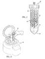
- FIG. 1is a kit of an apparatus according to various embodiments
- FIG. 2is an environmental view of a separating device according to the various embodiments
- FIG. 3illustrates the separating device being filled according to various embodiments
- FIG. 4is an environmental view of a filled separating device according to various embodiments.
- FIG. 5is an environmental view of a separating device at a centrifuge according to various embodiments
- FIG. 6is an environmental view of a separating device after being centrifuged
- FIG. 6Ais a schematic view of a separating device after being centrifuged
- FIG. 7is an environmental view of material being withdrawn from the separating device according to various embodiments.
- FIG. 7Ais a schematic view of the piston in the container while material is being withdrawn from the separating device according to various embodiments;
- FIG. 8illustrates the environmental view after a selected component has been withdrawn from the separating device
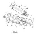
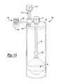
- FIG. 9is an exploded perspective view of a separation device according to various embodiments.
- FIG. 10is an assembled view of a separation device according to various embodiments.
- FIG. 11is a detail view of a syringe interacting with a separation device according to various embodiments.
- a componentcan be any appropriate portion of a whole, whether differing in density, specific gravity, buoyancy, structure, etc. The component is a portion that can be separated from the whole.
- a kit 20can be provided to allow for collection, separation, and application of a selected biological material or component.
- the kit 20can be understood to include any appropriate devices or materials, and the following devices are merely exemplary.
- the kit 20can include a separation device 30 that can be used to separate a selected material, such as an adipose tissue sample, a whole blood sample, or the like.
- the separation device 30can be disposable, reusable, or combinations thereof.
- the separation device 30can include a container 32 that may be reusable while a separation piston 34 is not.
- the kit 20can include a collection device such as a syringe 36 , an application device such as a syringe 38 , and a mixing material that may be included in a syringe 40 .
- the mixing materialmay be any appropriate material such as an anti-clotting agent, a clotting agent, an antibiotic, an enzyme, a buffer, a growth factor or factors, or the like.
- the kit 20may also include any other appropriate materials such as bandages, tourniquets, sterilization materials or the like. It will be further understood that the kit 20 may be provided sterilized, prepared for sterilization, or any appropriate combination thereof.
- the various syringes 36 , 38 , 40may be any generally known syringe.
- the syringe 36may also be interconnectable with a needle or cannula 42 that can interconnect with a luer fitting 44 of the syringe 36 .
- the syringe 36can generally include a container 46 and a plunger 48 . This can allow the syringe 36 to withdraw a selected sample, such as an adipose tissue sample from an anatomy, such as a human anatomy, for various purposes.
- the application syringe 38can also include a container 50 and a plunger 52 .
- the application syringe 38can be any appropriate syringe and can be of a size to interconnect with the selected portion of the separation device 30 , such as discussed herein.
- the mixing syringe 40can also include a container 54 and a plunger 56 .
- the mixing syringe 40can include any appropriate material, such as those described above.
- the mixing material provided in the mixing syringe 40The mixing material can be added to the container 32 at any appropriate time for interaction with the selected material that can also be positioned in the separation container 32 .
- the separation device 30includes the container or tube 32 that can include various features.
- container 32can be any appropriate size such as 20 ml, 40 ml, 60 ml, any combination thereof, fraction thereof, or any appropriate size.
- the collection container 32includes a side wall 60 that can assist in containing the material positioned in the container 32 .
- the tube 32may also include demarcations 62 that indicate a selected volume.
- the sidewall 60may or may not be flexible under a selected force.
- the separation device 30can be positioned in a centrifuge or similar device to apply an increased force of gravity to the material positioned in the tube 32 . If the tube 32 is formed of a selected material, the sidewall 60 may flex under the high force of gravity to cause an increased diameter of the tube 32 under the higher force of gravity.
- the sidewall 60 of the container 32may be formed of a substantially rigid material that will not flex under a high force of gravity.
- the tube 32further includes a top or proximal portion that defines a cap engaging region 64 .
- the cap engaging region 64can include a thread or partial threads 66 that can interconnect with a cap 68 .
- the cap 68can include an internal thread that can thread onto the thread 66 of the top portion 64 to fix the cap 68 relative to the tube 32 . Therefore, the cap 68 can be removed from the tube 32 , but it will be understood that the cap 68 can also be formed as an integral or single portion of the tube 32 .
- the separating device 30can be provided as a modular system or can be formed as an integral or unitary member.
- Extending through the cap 68can be a collection or application port 72 .
- the port 72can include a luer locking portion 74 , or any other appropriate interconnection portion.
- the port 72can also include or be connected to a cap 71 .
- the port 74can extend through the cap 68 to a withdrawal tube 76 .
- the withdrawal tube 76may be formed as a single piece with the port 72 or can be interconnectable with the port 72 .
- the withdrawal tube 76can extend through the piston 34 through a central channel 78 defined through the piston 34 .
- the withdrawal tube 76can define a conduit, such as an extraction conduit.
- a separate tube or cannulacan be passed relative to the piston 34 for withdrawal of a material or component of the sample. Thus, the withdrawal tube 76 need not be maintained in the tube 32 for an entire procedure.
- the withdrawal tube 76can, but is not required to, define a piston stop or stop member 80 .
- the stop 80can act as a stop member for the piston 34 so that the piston 34 is able to move only a selected distance along the withdrawal tube 76 .
- the stop 80can also be formed by any appropriate portion, such as the sidewall 60 .
- the stop 80is provided to assist in limiting a movement of the piston 34 . Therefore, it will be understood that the withdrawal tube 76 may also act as a rod on which the piston 34 is able to move.
- the piston 34can include any appropriate geometry such as a geometry that substantially mates with the tube 32 , particularly a distal end 82 of the tube 32 .
- the distal end of the tube 32can be flat, conical, tapered, etc. It will be understood, however, that the piston 34 can also include any other appropriate geometry to interact with the tube 32 .
- the piston 34can include a contacting or central region 84 that includes an outer dimension, such as a circumference or diameter that is generally equivalent to an inner diameter or circumference of the tube 32 . Therefore, the piston 34 can contact or engage the sidewall 60 of the tube 32 at a selected time.
- the piston 34can also be formed in any appropriate configuration or of any appropriate material.
- the pistonin addition to the selected geometry of the piston 34 , the piston can be porous, non-porous, or include regions of each.
- the piston 34can be formed of a porous material such as a screen, a filter, a mesh, or the like.
- the piston 34including a porous region, can allow a selected material to pass through and not allow other non-selected materials to pass. The piston 34 , therefore, can selectively separate materials or components of a sample.
- the middle or tube engaging portion 84 of the piston 34can include the dimension that is substantially similar to an unchanged or unforced dimension of the wall 60 of the tube 32 .
- itmay be formed so that there is substantially little space or a sliding engagement between the tube engaging portion 84 of the piston 34 and the tube 32 .
- the wall 60 of the tube 32can be compressed axially and be forced outward thereby increasing a dimension, such as a diameter, of the tube 32 .
- the increasing of the diameter of the tube 32 relative to the piston 34can allow for a freer movement or non-engagement of the tube 32 with the piston 34 . In this way, the piston 34 can move relative to the tube 32 or materials can move between the piston 34 and the tube 32 .
- the piston 34may move relative to the tube 32 when the tube is compressed, thus increasing the tube's 32 diameter.
- the piston 34can move relative to the withdrawal tube 76 , which can allow the piston 34 to move a selected distance relative to the tube 32 or the cap 68 .
- the stop 80which is provided on the withdrawal tube 76 , can assist in selectively stopping the piston 34 relative to the rod 76 . This can define a maximum motion of the piston 34 relative to the withdrawal tube 76 .
- a selected materialsuch as a biological material
- the tube 32can be positioned in a centrifuge with the piston 34 .
- the tube 32can compress, thereby increasing its diameter relative to the piston 34 .
- the compressioncan allow the piston 34 to more easily move relative to the withdrawal tube 76 and the container tube 32 . Therefore, the piston 34 can assist in separating a selected material positioned in the container tube 32 .
- the axial compression of the container tube 32can be reduced to thereby return it substantially to its original dimensions.
- its original dimensionscan be substantially similar to those of the piston 34 , particularly the tube engaging portion 84 , which can hold the piston 34 in a selected position relative to the tube 32 . This can assist in maintaining a separation of the material positioned in the tube 32 , as discussed herein.
- the separation system 30can be used with any appropriate process or various selected biological materials or multi-component materials. Nevertheless, the separation system 30 can be used to separate a selected biological material such as stromal cells, mesenchymal stem cells, blood components, adipose components or other appropriate biological or multi-component materials.
- a selected biological materialsuch as stromal cells, mesenchymal stem cells, blood components, adipose components or other appropriate biological or multi-component materials.
- a patient 90can be selected.
- the patient 90can include an appropriate anatomy and the collection device 36 can be used to collect a selected portion of biological material.
- the collection device 36can engage a portion of the patient 90 to withdraw a selected volume of adipose tissue.
- the adipose tissuecan be selected from any appropriate portion of the anatomy, such as from the abdominal region.
- various other componentsmay be withdrawn into the collection tube 36 , such as whole blood, stem cells, and the like.
- the collection device 36can be a plurality of collection devices that each collect different components, such as one to collect adipose tissue, one to collect whole blood, and others to collect other selected biological materials.
- the biological material 92can be placed into the tube 32 . Once the tube 32 has been filled an appropriate amount with the biological material 92 , the piston 34 , the rod 76 , and the cap 68 can be interconnected with the tube 32 .
- the assembled separation device 30can be pre-treated prior to various other processing steps.
- selected componentsincluding enzymes, chemicals, antibiotics, growth factors, and the like, can be added to the container tube 32 .
- the selected materialwhich can include adipose tissue, can be sonicated or treated with a sonic radiation prior to further processing steps.
- various other agitating methods or devicescan be used to mix or agitate the material.
- a mixing bead, beads, ball, or the likecan be placed in the container 32 . The container 32 can then be moved with the beads inside to agitate and mix the material.
- various rigid arms or extensionscan be positioned in the container 32 to assist in agitating or mixing the material.
- the sonication of the adipose tissuecan perform various steps.
- the sonication of the adipose tissuecan remove or release stromal cells from the adipose tissue cells.
- sonication of the adipose tissuecan be performed at any appropriate time.
- the sonication of the adipose tissuecan be performed once it has been collected into the collection device 36 and prior to being positioned in the tube 32 or after it has been positioned in the tube 32 .
- all of the selected materialswhich may include whole blood, various components of whole blood, or the like, can be also added to the tube 32 .
- the separation system 30can be positioned in an appropriate separation device, such as a centrifuge 94 .
- the centrifuge 94can be operated according to any appropriate technique to perform a high gravity separation of the material positioned in the separation device 30 . Nevertheless, the centrifuge device can be spun at any appropriate rotation per minute (RPM) such as about 2000 to about 4030 RPMs. This can form a force of gravity on the separation device 30 and the various materials positioned therein of about 740 G's to about 3000 G's.
- RPMrotation per minute
- the centrifugation step with the centrifuge device 94can be performed for any appropriate amount of time.
- the separation device 30can be spun at the selected RPMs for about 5 to about 15 minutes. It will be understood that one skilled in the art can determine an appropriate RPM and time setting which can be used to separate selected materials positioned in the separation device 30 . Further, the separation of different materials may require different RPMs and different separation times.
- the piston 34can be positioned in the tube 32 to assist in separating the materials positioned in the container tube 32 .
- the piston 34can be formed of any appropriate materials and according to any appropriate physical characteristics.
- the piston 34can be formed of a material or combination of materials that can achieve a selected density.
- the piston 34can assist in separating, such as physically separating, selected components of the biological material 92 positioned in the separation device 30 .
- the piston 34can include a density that is about 1.00 grams per milliliter to about 1.10 grams per milliliter, such as less than about 1.06 grams per cc or 1.06 grams per milliliter.
- the selected density of the piston 34can assist in separating denser components or components with a higher specific gravity than the piston 34 .
- stromal cellsinclude a specific gravity that is greater than other components of the biological material 92 positioned in the tube 32 and also greater than that of the piston 34 .
- the piston 34can include any appropriate density.
- the centrifuge 94can be spun.
- the forces produced by the centrifuge 94can compress the container tube 32 , which can increase its diameter thus allowing the piston 34 to move relative to the container 32 .
- the various components of the biological material 92 positioned in the separation tube 32can be physically separated by the piston 34 as it moves relative to the separation tube 32 . This can assist in moving at least one of the piston 34 or a portion of the biological material 92 .
- the biological materialcan originally be positioned on top of the piston 34 , the forces and/or flexing of the sidewall 60 can allow at least a component of the material to move past the piston 34 .
- the sidewall 60may not flex and that the material is simply forced past the piston 34 between the piston 34 and the sidewall 60 .
- the materialcan move past the piston 34 to the distal end 82 to container 32 according to any appropriate method such as flexing the sidewall 60 , moving between a space between the piston 34 and the sidewall 60 , or any other appropriate method.
- the biological material 92can be separated into a plurality of components that are contained within the separation container 32 .
- a first component 92 acan be positioned between the piston 34 , such as a distal end of the piston 34 a and the distal end of the separation container 82 .
- the first biological component 92 acan be any appropriate material, including stromal cells, mesenchymal stem cells or the like. If the biological material 92 positioned within the separation tube 32 includes adipose tissue, then various other components can include a plasma and plasma protein component 92 b and a fat and oil component 92 c . It will be understood, as illustrated in FIG.
- the fat and oil component 92 cis generally formed near a proximal end of the tube 32 while the denser stromal cells are formed as a cell button near the distal and 82 .
- various materialsincluding plasma and plasma proteins, may also include a density that is higher than that of the piston 34 and thus may also be formed or moved towards the distal end 82 of the separation tube 32 .
- the first component 92 acan include a high concentration of the high density materials that is of a selected material to be separated using the separation device 30 , because of the piston 34 and the stop 80 .
- the stop 80can extend from the withdrawal tube 76 to ensure a low concentration or low volume of the plasma, plasma proteins, or the materials that may include a density that is greater than that of the piston 34 . Although it may be selected to include a selected volume of the plasma or plasma proteins near the distal end 82 of the separation tube 32 , such as for withdrawal of the selected cells, such as stromal cells, it may be selected to keep the concentration at a selected amount. Therefore, the stop 80 or other stop or limiting portion (e.g.
- a lip or edge in the container 32can assist in achieving the selected volume and concentration of the first component 92 a to be separated by the separation device 30 as the piston 34 moves towards the stop 80 , as illustrated in FIGS. 6 and 6A , where the piston 34 is illustrated to have moved away from the distal end 82 of the container 32 .
- the withdrawal device 38can be interconnected with the withdrawal port 72 which interconnects the withdrawal device 38 with the withdrawal tube 76 .
- the withdrawal tube 76can pass through the piston 34 . Because the withdrawal tube 76 can be fixed relative to the cap 78 , the withdrawal tube 76 may not move during the centrifugation process. This allows the piston 34 to move relative to the separation tube 32 while the withdrawal tube 76 maintains its position, as illustrated in FIGS. 6 , 6 A, and 7 .
- the withdrawal tube 76can include a portion positioned generally near the distal portion 82 of the separation tube 32 . Therefore, the withdrawal port 72 can be interconnected or operable to remove a material that is positioned near the distal end 82 of the separation tube 32 .
- the piston 34can move proximally and allow for separation of a volume near the distal end 82 of the separation tube 32 , the withdrawal tube 76 is still positioned near the distal end 82 of the separation tube 32 . Therefore, the collection device 38 can be interconnected with the withdrawal port 72 and used to withdraw the volume of material that is positioned near the distal end of the tube 82 , as illustrated in FIGS. 6 , 6 A, and 7 .
- the separated materialwhich can include stromal cells or other appropriate biological components, can be withdrawn after being separated and concentrated with the separation system 30 .
- Other various components, such as the components 92 b and 92 c of the biological material 92can be retained in the tube 32 .
- the piston 34can be moved generally in the direction of the arrow A, as illustrated in FIGS. 7 and 7A , away from the stop 80 . This can allow for a displacement of the volume being removed into the collection tube 38 as the piston 34 moves in the direction of arrow A towards the distal end 82 of the separation tube 32 . Further, this movement of the piston 34 can assist in withdrawing the material from the distal end 82 of the separation tube 32 .
- the piston 34can remain or, again, move to substantially fill the internal volume of the distal portion 82 of the separation tube 32 as it moves toward the distal end 82 as the component is withdrawn. Therefore, the piston 34 can also assist in withdrawing the material from the separation tube 32 . Since the piston 34 can substantially fill the volume of the material 92 a being withdrawn from the separation tube 32 , it can help insure that substantially all of the volume of the material 92 a is withdrawn from the separation container 32 .
- the separation device 30can assist in separating, concentrating, and collecting a selected biological component of the biological material 92 . It will be understood that while collecting stromal cells from a sonicated adipose tissue is described that the separation, concentration, and collection of any selected biological component may be performed. One skilled in the art will understand that the separation device 30 can be used with any appropriate biological material that can be positioned in the separation tube 32 .
- the separation device 30can be used to separate and concentrate a selected volume of material from a substantially small volume of the whole biological material 92 . Because the separation system 30 includes the various components, including the withdrawal tube 76 that extends substantially the length of the separation container 32 , and the piston 34 , the biological material 92 can be effectively separated and concentrated into various components. The denser component 92 a can be easily withdrawn from the separation tube 32 without interference of the other components of the biological material 92 .
- the withdrawn materialwhich may include the stromal cells, can then be used for various purposes.
- the withdrawn materialcan include the selected biological component, such as stromal cells, mesenchymal stem cells, or other stem cells.
- the stromal cells that are collected from the selected biological material, such as adipose tissuecan be applied to various portions of the anatomy to assist in healing, growth, regeneration, and the like.
- an implantmay be positioned relative to a bony structure.
- the stromal cells or other componentscan be applied near the cite of the implantation, to the implant before implantation, to an area of removed bone, or the like, to assist in regeneration of growth of the bone.
- the stem cellssuch as the stromal or mesenchymal cells
- the separated and concentrated biological componentwhich can include the stromal cells or other appropriate biological components, can be applied to assist in regeneration, speed healing after a procedure, or other appropriate applications.
- the undifferentiated cellscan differentiate after implantation or placement in a selected portion of the anatomy.
- the cellscan release factors that direct the activity of other cells to assist in regeneration, speed healing, or other appropriate applications.
- the kit 20can include a separation device 100 that is similar to the separation device 30 . While the separation device 100 differs from the separation device 30 in various aspects those identical portions will be referenced with identical reference numerals.
- the separation device 100can include the separation container 32 or tube. Further, the separation device 100 can include the piston 34 . The piston 34 can be positioned within the tube 32 of the separation device 100 .
- the separation device 100can also include the cap or top wall 68 . According to various embodiments, the top wall 68 can be substantially fixed to a proximal end 102 of the tube 32 . As discussed above, the top wall 68 can also threadably engage a cap engaging region 64 of the tube 32 . An adhesive can be used to fix the cap or top wall 68 to the proximal end 102 of the tube 32 or the two can be formed as a single member.
- the separation device 100can differ from the separation device 30 according to various features.
- the separation device 100can include an injection port or second port 104 .
- the injection port 104can extend between an outlet end 106 and an inlet end 108 .
- the inlet end 108can also include a connection portion, such as a quarter turn or luer connection that can interconnect with an injection port extender 110 .
- the injection port extender 110can include a top or injection end 112 .
- a cap 114can be positioned over the top 112 of the extension 110 .
- the top 112can include a connection portion, such as a luer lock or other connection portion to connect with the cap 114 or an injection syringe, as discussed further herein.
- the separation device 100can also include a second injection port cap 116 .
- the second injection port cap 116can be tethered to the top wall 68 with a tether 118 .
- the second injection port cap 116can also include a sterile contact or holding member 120 that can be removed after use.
- the second injection port cap 116can include a luer connection or fixation port to connect to the injection port 104 at the top or connection portion 108 .
- the injection port 104allows the material to be injected through the top wall 68 into the tube 32 .
- the top wall 68can, therefore, be fixed to the proximal end 102 of the tube 32 while the material is being injected or delivered to the tube 32 .
- Thiscan allow the multi-component material 92 to be delivered into the tube 32 in an efficient manner and can also maintain the position of the piston 34 near the distal end 82 of the tube 32 .
- any appropriate mixing materialcan be added at any appropriate time from the syringe 40 or other source.
- the top wall or cap 68can be removed a small amount and the material 92 can be delivered through the top end or proximal end 102 of the tube 32 .
- Providing the injection port 104can provide a mechanism and port to inject the material into the injection tube without removing the cap 68 from the tube 32 .
- the collection device or syringe 36can be interconnected with the extension 110 that is interconnected with the injection port 104 .
- the collection syringe 36can be used to collect the multi-component fluid 92 .
- the multi-component fluid 92can be injected into the tube 32 of the separation device 100 .
- the separation device 100can include the top wall 68 substantially fixed to the tube 32 .
- the extraction port 72can also be positioned relative to the cap 68 and be interconnected with the conduit 76 .
- the extension 110can allow the collection syringe 36 to be interconnected with the injection port 104 in a manner that allows access without interference of the extraction port 72 .
- the extension 110can include the luer connection near the top end 112 of the extension 110 to interconnect with the collection syringe 36 . Therefore, the syringe 36 can be efficiently connected to the extension 110 which is connected to the injection port 104 .
- the extension 110can be removed from the injection port 104 .
- the second injection port cap 116can be interconnected with the injection port 104 .
- the sterile holder 120 on the second injection port cap 116can be used to effectively maintain sterility between the second injection port cap 116 and the injection port 104 .
- the second injection port cap 116can be positioned over the injection port 104 during the centrifugation process and the extraction process from the tube 32 .
- the separation device 100can be used in a manner substantially identical to the separation device 30 , discussed above. It will be understood that the extension 110 is not required, and can be provided according to various embodiments or when selected by a user. Further, the separation device 100 can be included in the kit 20 , either with the separation device 30 or as an alternative thereto. Therefore, one skilled in the art will understand, the separation device 100 can be included with the kit 20 and used as the separation device 30 discussed above. In addition the separation devices 30 , 100 and the kit 20 can be used in various procedures, such as wound healing, including stromal cells from adipose tissue and other blood components, as taught in U.S. Provisional Application No. 60/900,758, filed on Feb. 9, 2007, incorporated herein by reference.
Landscapes
- Health & Medical Sciences (AREA)
- Chemical & Material Sciences (AREA)
- Analytical Chemistry (AREA)
- General Health & Medical Sciences (AREA)
- Hematology (AREA)
- Clinical Laboratory Science (AREA)
- Chemical Kinetics & Catalysis (AREA)
- Apparatus Associated With Microorganisms And Enzymes (AREA)
Abstract
Description
Claims (17)
Priority Applications (3)
| Application Number | Priority Date | Filing Date | Title |
|---|---|---|---|
| US11/744,093US8048297B2 (en) | 2005-08-23 | 2007-05-03 | Method and apparatus for collecting biological materials |
| US13/285,436US8236258B2 (en) | 2005-08-23 | 2011-10-31 | Method and apparatus for collecting biological materials |
| US13/567,755US8512575B2 (en) | 2005-08-23 | 2012-08-06 | Method and apparatus for collecting biological materials |
Applications Claiming Priority (3)
| Application Number | Priority Date | Filing Date | Title |
|---|---|---|---|
| US11/210,005US7771590B2 (en) | 2005-08-23 | 2005-08-23 | Method and apparatus for collecting biological materials |
| US90075807P | 2007-02-09 | 2007-02-09 | |
| US11/744,093US8048297B2 (en) | 2005-08-23 | 2007-05-03 | Method and apparatus for collecting biological materials |
Related Parent Applications (1)
| Application Number | Title | Priority Date | Filing Date |
|---|---|---|---|
| US11/210,005Continuation-In-PartUS7771590B2 (en) | 2005-08-23 | 2005-08-23 | Method and apparatus for collecting biological materials |
Related Child Applications (1)
| Application Number | Title | Priority Date | Filing Date |
|---|---|---|---|
| US13/285,436ContinuationUS8236258B2 (en) | 2005-08-23 | 2011-10-31 | Method and apparatus for collecting biological materials |
Publications (2)
| Publication Number | Publication Date |
|---|---|
| US20070208321A1 US20070208321A1 (en) | 2007-09-06 |
| US8048297B2true US8048297B2 (en) | 2011-11-01 |
Family
ID=46327830
Family Applications (3)
| Application Number | Title | Priority Date | Filing Date |
|---|---|---|---|
| US11/744,093Active2028-12-21US8048297B2 (en) | 2005-08-23 | 2007-05-03 | Method and apparatus for collecting biological materials |
| US13/285,436Expired - Fee RelatedUS8236258B2 (en) | 2005-08-23 | 2011-10-31 | Method and apparatus for collecting biological materials |
| US13/567,755Expired - Fee RelatedUS8512575B2 (en) | 2005-08-23 | 2012-08-06 | Method and apparatus for collecting biological materials |
Family Applications After (2)
| Application Number | Title | Priority Date | Filing Date |
|---|---|---|---|
| US13/285,436Expired - Fee RelatedUS8236258B2 (en) | 2005-08-23 | 2011-10-31 | Method and apparatus for collecting biological materials |
| US13/567,755Expired - Fee RelatedUS8512575B2 (en) | 2005-08-23 | 2012-08-06 | Method and apparatus for collecting biological materials |
Country Status (1)
| Country | Link |
|---|---|
| US (3) | US8048297B2 (en) |
Cited By (25)
| Publication number | Priority date | Publication date | Assignee | Title |
|---|---|---|---|---|
| US8512575B2 (en) | 2005-08-23 | 2013-08-20 | Biomet Biologics, Llc | Method and apparatus for collecting biological materials |
| WO2014144505A2 (en) | 2013-03-15 | 2014-09-18 | Biomet Biologics, Llc | Methods for making cytokine compositions from tissues using non-centrifugal methods |
| WO2014149301A1 (en) | 2013-03-15 | 2014-09-25 | Biomet Biologics, Llc | Methods and non-immunogenic compositions for treating inflammatory disorders |
| WO2014149300A1 (en) | 2013-03-15 | 2014-09-25 | Biomet Biologics, Llc | Treatment of inflammatory respiratory disease using biological solutions |
| WO2014149270A1 (en) | 2013-03-15 | 2014-09-25 | Biomet Biologics, Llc | Treatment of pain using protein solutions |
| WO2014149979A1 (en) | 2013-03-15 | 2014-09-25 | Biomet Biologics, Llc | Treatment of peripheral vascular disease using protein solutions |
| WO2015081253A1 (en) | 2013-11-26 | 2015-06-04 | Biomet Biologics, Llc | Methods of mediating macrophage phenotypes |
| US9308224B2 (en) | 2008-02-27 | 2016-04-12 | Biomet Biologics, Llc | Methods and compositions for delivering interleukin-1 receptor antagonist |
| US9364828B2 (en) | 2009-05-15 | 2016-06-14 | Becton, Dickinson And Company | Density phase separation device |
| US9694359B2 (en) | 2014-11-13 | 2017-07-04 | Becton, Dickinson And Company | Mechanical separator for a biological fluid |
| US9701728B2 (en) | 2008-02-27 | 2017-07-11 | Biomet Biologics, Llc | Methods and compositions for delivering interleukin-1 receptor antagonist |
| US9758806B2 (en) | 2013-03-15 | 2017-09-12 | Biomet Biologics, Llc | Acellular compositions for treating inflammatory disorders |
| US9763875B2 (en) | 2009-08-27 | 2017-09-19 | Biomet Biologics, Llc | Implantable device for production of interleukin-1 receptor antagonist |
| US10272445B2 (en) | 2015-11-24 | 2019-04-30 | Royal Biologics | Methods and apparatus for separating fluid components |
| US10441635B2 (en) | 2014-11-10 | 2019-10-15 | Biomet Biologics, Llc | Methods of treating pain using protein solutions |
| US10576130B2 (en) | 2013-03-15 | 2020-03-03 | Biomet Manufacturing, Llc | Treatment of collagen defects using protein solutions |
| US10729552B2 (en) | 2015-03-18 | 2020-08-04 | Biomet C.V. | Implant configured for hammertoe and small bone fixation |
| US11013602B2 (en) | 2016-07-08 | 2021-05-25 | Mako Surgical Corp. | Scaffold for alloprosthetic composite implant |
| US11090646B2 (en) | 2017-07-27 | 2021-08-17 | Biomerieux, Inc. | Isolation tube |
| US11478787B2 (en) | 2018-07-09 | 2022-10-25 | Hanuman Pelican, Inc. | Apparatus and methods for separating blood components |
| US11534533B2 (en) | 2018-07-09 | 2022-12-27 | Hanuman Pelican, Inc. | Apparatus and methods for processing blood |
| US11559613B2 (en) | 2019-02-06 | 2023-01-24 | Hanuman Pelican, Inc. | Apparatus and methods for concentrating platelet-rich plasma |
| US11654428B2 (en) | 2019-01-21 | 2023-05-23 | Vias Partners, Llc | Methods, systems and apparatus for separating components of a biological sample |
| US12007382B2 (en) | 2019-10-31 | 2024-06-11 | Crown Laboratories, Inc. | Systems, methods and apparatus for separating components of a sample |
| US12440835B2 (en) | 2020-01-21 | 2025-10-14 | Vias Partners, Llc | Methods, systems and apparatus for separating components of a biological sample |
Families Citing this family (34)
| Publication number | Priority date | Publication date | Assignee | Title |
|---|---|---|---|---|
| US7992725B2 (en)* | 2002-05-03 | 2011-08-09 | Biomet Biologics, Llc | Buoy suspension fractionation system |
| US20030205538A1 (en) | 2002-05-03 | 2003-11-06 | Randel Dorian | Methods and apparatus for isolating platelets from blood |
| US7832566B2 (en) | 2002-05-24 | 2010-11-16 | Biomet Biologics, Llc | Method and apparatus for separating and concentrating a component from a multi-component material including macroparticles |
| US7845499B2 (en) | 2002-05-24 | 2010-12-07 | Biomet Biologics, Llc | Apparatus and method for separating and concentrating fluids containing multiple components |
| US20060278588A1 (en) | 2002-05-24 | 2006-12-14 | Woodell-May Jennifer E | Apparatus and method for separating and concentrating fluids containing multiple components |
| WO2003099412A1 (en) | 2002-05-24 | 2003-12-04 | Biomet Manufacturing Corp. | Apparatus and method for separating and concentrating fluids containing multiple components |
| US7771590B2 (en)* | 2005-08-23 | 2010-08-10 | Biomet Manufacturing Corp. | Method and apparatus for collecting biological materials |
| US8567609B2 (en) | 2006-05-25 | 2013-10-29 | Biomet Biologics, Llc | Apparatus and method for separating and concentrating fluids containing multiple components |
| US8034014B2 (en) | 2007-03-06 | 2011-10-11 | Biomet Biologics, Llc | Angiogenesis initation and growth |
| JP5479319B2 (en) | 2007-04-12 | 2014-04-23 | バイオメット・バイオロジックス・リミテッド・ライアビリティ・カンパニー | Buoy suspension fractionation system |
| US8328024B2 (en) | 2007-04-12 | 2012-12-11 | Hanuman, Llc | Buoy suspension fractionation system |
| US20080269762A1 (en)* | 2007-04-25 | 2008-10-30 | Biomet Manufacturing Corp. | Method and device for repair of cartilage defects |
| US7901344B2 (en)* | 2007-05-11 | 2011-03-08 | Biomet Biologics, Llc | Methods of reducing surgical complications in cancer patients |
| ATE545441T1 (en)* | 2007-06-13 | 2012-03-15 | Pervasis Therapeutics Inc | METHOD AND DEVICE FOR THE MINIMALLY INVASIVE DELIVERY OF CELL-CONTAINING FLOWABLE COMPOSITIONS |
| US20090192528A1 (en)* | 2008-01-29 | 2009-07-30 | Biomet Biologics, Inc. | Method and device for hernia repair |
| US8337711B2 (en) | 2008-02-29 | 2012-12-25 | Biomet Biologics, Llc | System and process for separating a material |
| US8309343B2 (en) | 2008-12-01 | 2012-11-13 | Baxter International Inc. | Apparatus and method for processing biological material |
| US8187475B2 (en) | 2009-03-06 | 2012-05-29 | Biomet Biologics, Llc | Method and apparatus for producing autologous thrombin |
| US8313954B2 (en) | 2009-04-03 | 2012-11-20 | Biomet Biologics, Llc | All-in-one means of separating blood components |
| US9011800B2 (en) | 2009-07-16 | 2015-04-21 | Biomet Biologics, Llc | Method and apparatus for separating biological materials |
| US20110052561A1 (en) | 2009-08-27 | 2011-03-03 | Biomet Biologics,LLC | Osteolysis treatment |
| JP4766176B2 (en)* | 2010-02-15 | 2011-09-07 | 横浜ゴム株式会社 | Adhesive of carbon thin film coated article and rubber |
| US8591391B2 (en) | 2010-04-12 | 2013-11-26 | Biomet Biologics, Llc | Method and apparatus for separating a material |
| US11213365B1 (en)* | 2010-05-19 | 2022-01-04 | Michael Angelillo | Arthrocentesis kit device |
| USD665075S1 (en)* | 2010-06-11 | 2012-08-07 | Infopia Co., Ltd. | Sample collection and injection device |
| WO2012001607A1 (en)* | 2010-06-29 | 2012-01-05 | Yadav, Omprakash | Disposable homogenizer kit |
| EP2611456A2 (en) | 2010-09-03 | 2013-07-10 | Biomet Biologics, LLC | Methods and compositions for delivering interleukin-1 receptor antagonist |
| US9011846B2 (en) | 2011-05-02 | 2015-04-21 | Biomet Biologics, Llc | Thrombin isolated from blood and blood fractions |
| WO2013025869A1 (en)* | 2011-08-17 | 2013-02-21 | Harvest Technologies Corporation | Segregation of oils in the fractionation of aspirated adipose tissues |
| US9642956B2 (en) | 2012-08-27 | 2017-05-09 | Biomet Biologics, Llc | Apparatus and method for separating and concentrating fluids containing multiple components |
| US20150076069A1 (en)* | 2013-09-13 | 2015-03-19 | Scientific Plastic Products, Inc. | Filter vial with limited piston stroke |
| EP3735279B1 (en)* | 2018-01-29 | 2025-05-14 | Forever Labs, Inc. | System and method for isolating extracellular vesicles |
| US11229722B2 (en)* | 2018-01-29 | 2022-01-25 | Omer Peled | System and method for harvesting autologous adipose tissue |
| WO2025166434A1 (en)* | 2024-02-06 | 2025-08-14 | Silimed Indústria De Implantes, Ltda. | Systems and methods for performing an autologous adipose tissue transplant |
Citations (76)
| Publication number | Priority date | Publication date | Assignee | Title |
|---|---|---|---|---|
| US280820A (en) | 1883-07-10 | Milk-can | ||
| US593333A (en) | 1897-11-09 | Device for separating liquids of different | ||
| US3409165A (en) | 1967-04-03 | 1968-11-05 | Olin Mathieson | Floating deck |
| US3508653A (en) | 1967-11-17 | 1970-04-28 | Charles M Coleman | Method and apparatus for fluid handling and separation |
| US3545671A (en) | 1967-02-14 | 1970-12-08 | Eugene Ross Lab Inc | Apparatus for and method of collecting,storing,separating and dispensing blood and blood components |
| US3814248A (en) | 1971-09-07 | 1974-06-04 | Corning Glass Works | Method and apparatus for fluid collection and/or partitioning |
| US3897343A (en) | 1974-02-27 | 1975-07-29 | Becton Dickinson Co | Plasma separator-hydrostatic pressure type |
| US3896733A (en) | 1973-10-18 | 1975-07-29 | Pall Corp | Autotransfusion apparatus |
| US3909419A (en) | 1974-02-27 | 1975-09-30 | Becton Dickinson Co | Plasma separator with squeezed sealant |
| US3931018A (en) | 1974-08-09 | 1976-01-06 | Becton, Dickinson And Company | Assembly for collection, separation and filtration of blood |
| US3957654A (en) | 1974-02-27 | 1976-05-18 | Becton, Dickinson And Company | Plasma separator with barrier to eject sealant |
| US4001122A (en) | 1973-08-22 | 1977-01-04 | Telan Corporation | Method and device for separating blood components |
| US4046699A (en) | 1976-11-01 | 1977-09-06 | Corning Glass Works | Access device for centrifugal separation assemblies |
| US4055501A (en) | 1976-01-16 | 1977-10-25 | Sherwood Medical Industries Inc. | Fluid collection device with phase partitioning means |
| US4077396A (en) | 1976-04-02 | 1978-03-07 | Wardlaw Stephen C | Material layer volume determination |
| US4152270A (en) | 1976-05-06 | 1979-05-01 | Sherwood Medical Industries Inc. | Phase separation device |
| US4187979A (en) | 1978-09-21 | 1980-02-12 | Baxter Travenol Laboratories, Inc. | Method and system for fractionating a quantity of blood into the components thereof |
| US4303193A (en) | 1979-01-22 | 1981-12-01 | Haemonetics Corporation | Apparatus for separating blood into components thereof |
| US4511662A (en) | 1982-06-18 | 1985-04-16 | Bio-Rad Laboratories, Inc. | Simultaneous assay for T and B lymphocyte populations and subpopulations |
| US4818386A (en) | 1987-10-08 | 1989-04-04 | Becton, Dickinson And Company | Device for separating the components of a liquid sample having higher and lower specific gravities |
| US4850952A (en) | 1985-09-10 | 1989-07-25 | Figdor Carl G | Method and device for the separation and isolation of blood or bone marrow components |
| US4917801A (en) | 1984-12-04 | 1990-04-17 | Becton Dickinson And Company | Lymphocyte collection tube |
| US4939081A (en) | 1987-05-27 | 1990-07-03 | The Netherlands Cancer Institute | Cell-separation |
| US5019243A (en) | 1987-04-03 | 1991-05-28 | Mcewen James A | Apparatus for collecting blood |
| US5024613A (en) | 1988-07-18 | 1991-06-18 | Pfizer Hospital Products Group, Inc. | Blood recovery system and method |
| US5053134A (en) | 1984-12-04 | 1991-10-01 | Becton Dickinson And Company | Lymphocyte collection tube |
| US5197985A (en) | 1990-11-16 | 1993-03-30 | Caplan Arnold I | Method for enhancing the implantation and differentiation of marrow-derived mesenchymal cells |
| US5207638A (en) | 1989-08-24 | 1993-05-04 | Hemotrans, Inc. | Blood transfer apparatus |
| US5269927A (en) | 1991-05-29 | 1993-12-14 | Sherwood Medical Company | Separation device for use in blood collection tubes |
| US5271852A (en) | 1992-05-01 | 1993-12-21 | E. I. Du Pont De Nemours And Company | Centrifugal methods using a phase-separation tube |
| US5456885A (en) | 1993-07-12 | 1995-10-10 | Coleman; Charles M. | Fluid collection, separation and dispensing tube |
| US5474687A (en) | 1994-08-31 | 1995-12-12 | Activated Cell Therapy, Inc. | Methods for enriching CD34+ human hematopoietic progenitor cells |
| US5560830A (en) | 1994-12-13 | 1996-10-01 | Coleman; Charles M. | Separator float and tubular body for blood collection and separation and method of use thereof |
| US5588958A (en) | 1994-09-21 | 1996-12-31 | C. R. Bard, Inc. | Closed wound orthopaedic drainage and autotransfusion system |
| US5632905A (en) | 1995-08-07 | 1997-05-27 | Haynes; John L. | Method and apparatus for separating formed and unformed components |
| US5646004A (en) | 1994-08-31 | 1997-07-08 | Activated Cell Therapy, Inc. | Methods for enriching fetal cells from maternal body fluids |
| US5645540A (en) | 1994-10-11 | 1997-07-08 | Stryker Corporation | Blood conservation system |
| US5648223A (en) | 1994-08-31 | 1997-07-15 | Activated Cell Therapy, Inc. | Methods for enriching breast tumor cells |
| US5663051A (en) | 1994-08-31 | 1997-09-02 | Activated Cell Therapy, Inc. | Separation apparatus and method |
| US5707876A (en) | 1996-03-25 | 1998-01-13 | Stephen C. Wardlaw | Method and apparatus for harvesting constituent layers from a centrifuged material mixture |
| US5707647A (en) | 1994-04-08 | 1998-01-13 | Atrix Laboratories, Inc. | Adjunctive polymer system for use with medical device |
| US5736033A (en) | 1995-12-13 | 1998-04-07 | Coleman; Charles M. | Separator float for blood collection tubes with water swellable material |
| US5738796A (en) | 1994-02-25 | 1998-04-14 | Pall Corporation | Method for separating components from a biological fluid |
| US5785700A (en) | 1992-06-03 | 1998-07-28 | Zimmer Patient Care, A Division Of Zimmer, Inc. | Autotransfusion system with portable detachable vacuum source |
| US5811151A (en) | 1996-05-31 | 1998-09-22 | Medtronic, Inc. | Method of modifying the surface of a medical device |
| US5823986A (en) | 1995-02-08 | 1998-10-20 | Medtronic, Inc. | Perfusion system |
| US5824084A (en) | 1996-07-03 | 1998-10-20 | The Cleveland Clinic Foundation | Method of preparing a composite bone graft |
| US5840502A (en) | 1994-08-31 | 1998-11-24 | Activated Cell Therapy, Inc. | Methods for enriching specific cell-types by density gradient centrifugation |
| US5916743A (en) | 1990-09-13 | 1999-06-29 | Baxter International Inc. | Continuous process for the separation of biologic components from heterogeneous cell populations |
| US5938621A (en) | 1997-09-12 | 1999-08-17 | Becton Dickinson And Company | Collection container assembly |
| US5955032A (en) | 1997-09-12 | 1999-09-21 | Becton Dickinson And Company | Collection container assembly |
| US5958253A (en) | 1994-12-02 | 1999-09-28 | Bristol-Myers Squibb Company | Centrifuge reagent delivery method |
| US6053856A (en) | 1995-04-18 | 2000-04-25 | Cobe Laboratories | Tubing set apparatus and method for separation of fluid components |
| US6063297A (en) | 1994-12-07 | 2000-05-16 | Plasmaseal Llc | Method and apparatus for making concentrated plasma and/or tissue sealant |
| US6071422A (en) | 1995-04-18 | 2000-06-06 | Cobe Laboratories, Inc. | Particle separation method and apparatus |
| WO2000061256A1 (en) | 1999-04-12 | 2000-10-19 | Harvest Technologies Corporation | Method and apparatus for producing platelet rich plasma and/or platelet concentrate |
| US6153113A (en) | 1999-02-22 | 2000-11-28 | Cobe Laboratories, Inc. | Method for using ligands in particle separation |
| US6264890B1 (en) | 1997-01-15 | 2001-07-24 | Boehringer Labiratories, Inc. | Method and apparatus for collecting and processing blood |
| US6280400B1 (en) | 1998-12-05 | 2001-08-28 | Becton Dickinson And Company | Device and method for separating component of a liquid sample |
| WO2001083068A1 (en) | 2000-04-28 | 2001-11-08 | Harvest Technologies Corporation | Blood components separator disk |
| US6328765B1 (en) | 1998-12-03 | 2001-12-11 | Gore Enterprise Holdings, Inc. | Methods and articles for regenerating living tissue |
| US20020035820A1 (en) | 1998-10-01 | 2002-03-28 | Barry Farris | Needleless method and apparatus for transferring liquid from a container to an injecting device without ambient air contamination |
| US6406671B1 (en) | 1998-12-05 | 2002-06-18 | Becton, Dickinson And Company | Device and method for separating components of a fluid sample |
| US20020104808A1 (en) | 2000-06-30 | 2002-08-08 | Lou Blasetti | Method and apparatus for producing platelet rich plasma and/or platelet concentrate |
| US6440444B2 (en) | 1999-02-23 | 2002-08-27 | Osteotech, Inc. | Load bearing osteoimplant and method of repairing bone using the same |
| US20020161449A1 (en) | 2001-02-28 | 2002-10-31 | Muschler George F. | Composite bone marrow graft material with method and kit |
| US20020182664A1 (en) | 2001-04-09 | 2002-12-05 | Dolecek Victor D. | Methods of isolating blood components using a microcentrifuge and uses thereof |
| US6508778B1 (en) | 1998-06-01 | 2003-01-21 | Harvest Technologies Corporation | System for withdrawal of blood |
| US20030050709A1 (en) | 2001-02-23 | 2003-03-13 | Ulrich Noth | Trabecular bone-derived human mesenchymal stem cells |
| US20030050710A1 (en) | 2001-09-06 | 2003-03-13 | Petersen Donald W. | Bone graft substitute composition |
| US6558341B1 (en) | 1996-05-07 | 2003-05-06 | Sherwood Services, Ag | Continuous autotransfusion filtration system |
| US20030185803A1 (en) | 2002-03-29 | 2003-10-02 | Sudhakar Kadiyala | Autologous bone graft material |
| US6629919B2 (en) | 1999-06-03 | 2003-10-07 | Haemonetics Corporation | Core for blood processing apparatus |
| US20030205538A1 (en) | 2002-05-03 | 2003-11-06 | Randel Dorian | Methods and apparatus for isolating platelets from blood |
| US6716187B1 (en) | 1999-07-08 | 2004-04-06 | Implant Innovations, Inc. | Platelet concentration syringe kit |
| US20080193424A1 (en) | 2007-02-09 | 2008-08-14 | Biomet Biologics, Inc. | Treatment of tissue defects with a therapeutic composition |
Family Cites Families (8)
| Publication number | Priority date | Publication date | Assignee | Title |
|---|---|---|---|---|
| US4189385A (en)* | 1977-05-03 | 1980-02-19 | Greenspan Donald J | Method and apparatus for separating serum or plasma from the formed elements of the blood |
| US4202769A (en)* | 1977-06-16 | 1980-05-13 | Greenspan Donald J | Method for separating serum or plasma from the formed elements of blood |
| US6200606B1 (en)* | 1996-01-16 | 2001-03-13 | Depuy Orthopaedics, Inc. | Isolation of precursor cells from hematopoietic and nonhematopoietic tissues and their use in vivo bone and cartilage regeneration |
| US5842477A (en) | 1996-02-21 | 1998-12-01 | Advanced Tissue Sciences, Inc. | Method for repairing cartilage |
| US7608258B2 (en) | 2002-04-13 | 2009-10-27 | Allan Mishra | Method for treatment of tendinosis using platelet rich plasma |
| US20040256331A1 (en) | 2002-10-04 | 2004-12-23 | Arking E. James | System and method for fractionation of a centrifuged sample |
| US8048297B2 (en) | 2005-08-23 | 2011-11-01 | Biomet Biologics, Llc | Method and apparatus for collecting biological materials |
| US7771590B2 (en) | 2005-08-23 | 2010-08-10 | Biomet Manufacturing Corp. | Method and apparatus for collecting biological materials |
- 2007
- 2007-05-03USUS11/744,093patent/US8048297B2/enactiveActive
- 2011
- 2011-10-31USUS13/285,436patent/US8236258B2/ennot_activeExpired - Fee Related
- 2012
- 2012-08-06USUS13/567,755patent/US8512575B2/ennot_activeExpired - Fee Related
Patent Citations (80)
| Publication number | Priority date | Publication date | Assignee | Title |
|---|---|---|---|---|
| US593333A (en) | 1897-11-09 | Device for separating liquids of different | ||
| US280820A (en) | 1883-07-10 | Milk-can | ||
| US3545671A (en) | 1967-02-14 | 1970-12-08 | Eugene Ross Lab Inc | Apparatus for and method of collecting,storing,separating and dispensing blood and blood components |
| US3409165A (en) | 1967-04-03 | 1968-11-05 | Olin Mathieson | Floating deck |
| US3508653A (en) | 1967-11-17 | 1970-04-28 | Charles M Coleman | Method and apparatus for fluid handling and separation |
| US3814248A (en) | 1971-09-07 | 1974-06-04 | Corning Glass Works | Method and apparatus for fluid collection and/or partitioning |
| US4001122A (en) | 1973-08-22 | 1977-01-04 | Telan Corporation | Method and device for separating blood components |
| US3896733A (en) | 1973-10-18 | 1975-07-29 | Pall Corp | Autotransfusion apparatus |
| US3897343A (en) | 1974-02-27 | 1975-07-29 | Becton Dickinson Co | Plasma separator-hydrostatic pressure type |
| US3957654A (en) | 1974-02-27 | 1976-05-18 | Becton, Dickinson And Company | Plasma separator with barrier to eject sealant |
| US3909419A (en) | 1974-02-27 | 1975-09-30 | Becton Dickinson Co | Plasma separator with squeezed sealant |
| US3931018A (en) | 1974-08-09 | 1976-01-06 | Becton, Dickinson And Company | Assembly for collection, separation and filtration of blood |
| US4055501A (en) | 1976-01-16 | 1977-10-25 | Sherwood Medical Industries Inc. | Fluid collection device with phase partitioning means |
| US4077396A (en) | 1976-04-02 | 1978-03-07 | Wardlaw Stephen C | Material layer volume determination |
| US4152270A (en) | 1976-05-06 | 1979-05-01 | Sherwood Medical Industries Inc. | Phase separation device |
| US4046699A (en) | 1976-11-01 | 1977-09-06 | Corning Glass Works | Access device for centrifugal separation assemblies |
| US4187979A (en) | 1978-09-21 | 1980-02-12 | Baxter Travenol Laboratories, Inc. | Method and system for fractionating a quantity of blood into the components thereof |
| US4303193A (en) | 1979-01-22 | 1981-12-01 | Haemonetics Corporation | Apparatus for separating blood into components thereof |
| US4511662A (en) | 1982-06-18 | 1985-04-16 | Bio-Rad Laboratories, Inc. | Simultaneous assay for T and B lymphocyte populations and subpopulations |
| US4917801A (en) | 1984-12-04 | 1990-04-17 | Becton Dickinson And Company | Lymphocyte collection tube |
| US5053134A (en) | 1984-12-04 | 1991-10-01 | Becton Dickinson And Company | Lymphocyte collection tube |
| US4850952A (en) | 1985-09-10 | 1989-07-25 | Figdor Carl G | Method and device for the separation and isolation of blood or bone marrow components |
| US5019243A (en) | 1987-04-03 | 1991-05-28 | Mcewen James A | Apparatus for collecting blood |
| US4939081A (en) | 1987-05-27 | 1990-07-03 | The Netherlands Cancer Institute | Cell-separation |
| US4818386A (en) | 1987-10-08 | 1989-04-04 | Becton, Dickinson And Company | Device for separating the components of a liquid sample having higher and lower specific gravities |
| US5024613A (en) | 1988-07-18 | 1991-06-18 | Pfizer Hospital Products Group, Inc. | Blood recovery system and method |
| US5207638A (en) | 1989-08-24 | 1993-05-04 | Hemotrans, Inc. | Blood transfer apparatus |
| US6221315B1 (en) | 1990-09-13 | 2001-04-24 | Baxter International Inc. | Apparatus for separation of biologic components from heterogeneous cell populations |
| US20010009757A1 (en) | 1990-09-13 | 2001-07-26 | Bischof Daniel F. | Apparatus for the separation of biologic components from heterogeneous cell populations |
| US5916743A (en) | 1990-09-13 | 1999-06-29 | Baxter International Inc. | Continuous process for the separation of biologic components from heterogeneous cell populations |
| US5197985A (en) | 1990-11-16 | 1993-03-30 | Caplan Arnold I | Method for enhancing the implantation and differentiation of marrow-derived mesenchymal cells |
| US5269927A (en) | 1991-05-29 | 1993-12-14 | Sherwood Medical Company | Separation device for use in blood collection tubes |
| US5271852A (en) | 1992-05-01 | 1993-12-21 | E. I. Du Pont De Nemours And Company | Centrifugal methods using a phase-separation tube |
| US5785700A (en) | 1992-06-03 | 1998-07-28 | Zimmer Patient Care, A Division Of Zimmer, Inc. | Autotransfusion system with portable detachable vacuum source |
| US5456885A (en) | 1993-07-12 | 1995-10-10 | Coleman; Charles M. | Fluid collection, separation and dispensing tube |
| US5738796A (en) | 1994-02-25 | 1998-04-14 | Pall Corporation | Method for separating components from a biological fluid |
| US5707647A (en) | 1994-04-08 | 1998-01-13 | Atrix Laboratories, Inc. | Adjunctive polymer system for use with medical device |
| US5646004A (en) | 1994-08-31 | 1997-07-08 | Activated Cell Therapy, Inc. | Methods for enriching fetal cells from maternal body fluids |
| US5840502A (en) | 1994-08-31 | 1998-11-24 | Activated Cell Therapy, Inc. | Methods for enriching specific cell-types by density gradient centrifugation |
| US5648223A (en) | 1994-08-31 | 1997-07-15 | Activated Cell Therapy, Inc. | Methods for enriching breast tumor cells |
| US5663051A (en) | 1994-08-31 | 1997-09-02 | Activated Cell Therapy, Inc. | Separation apparatus and method |
| US5474687A (en) | 1994-08-31 | 1995-12-12 | Activated Cell Therapy, Inc. | Methods for enriching CD34+ human hematopoietic progenitor cells |
| US5588958A (en) | 1994-09-21 | 1996-12-31 | C. R. Bard, Inc. | Closed wound orthopaedic drainage and autotransfusion system |
| US5645540A (en) | 1994-10-11 | 1997-07-08 | Stryker Corporation | Blood conservation system |
| US5958253A (en) | 1994-12-02 | 1999-09-28 | Bristol-Myers Squibb Company | Centrifuge reagent delivery method |
| US6214338B1 (en) | 1994-12-07 | 2001-04-10 | Plasmaseal Llc | Plasma concentrate and method of processing blood for same |
| US6063297A (en) | 1994-12-07 | 2000-05-16 | Plasmaseal Llc | Method and apparatus for making concentrated plasma and/or tissue sealant |
| US5560830A (en) | 1994-12-13 | 1996-10-01 | Coleman; Charles M. | Separator float and tubular body for blood collection and separation and method of use thereof |
| US5823986A (en) | 1995-02-08 | 1998-10-20 | Medtronic, Inc. | Perfusion system |
| US6053856A (en) | 1995-04-18 | 2000-04-25 | Cobe Laboratories | Tubing set apparatus and method for separation of fluid components |
| US6071422A (en) | 1995-04-18 | 2000-06-06 | Cobe Laboratories, Inc. | Particle separation method and apparatus |
| US5632905A (en) | 1995-08-07 | 1997-05-27 | Haynes; John L. | Method and apparatus for separating formed and unformed components |
| US5736033A (en) | 1995-12-13 | 1998-04-07 | Coleman; Charles M. | Separator float for blood collection tubes with water swellable material |
| US5707876A (en) | 1996-03-25 | 1998-01-13 | Stephen C. Wardlaw | Method and apparatus for harvesting constituent layers from a centrifuged material mixture |
| US6558341B1 (en) | 1996-05-07 | 2003-05-06 | Sherwood Services, Ag | Continuous autotransfusion filtration system |
| US5811151A (en) | 1996-05-31 | 1998-09-22 | Medtronic, Inc. | Method of modifying the surface of a medical device |
| US5824084A (en) | 1996-07-03 | 1998-10-20 | The Cleveland Clinic Foundation | Method of preparing a composite bone graft |
| US6264890B1 (en) | 1997-01-15 | 2001-07-24 | Boehringer Labiratories, Inc. | Method and apparatus for collecting and processing blood |
| US5938621A (en) | 1997-09-12 | 1999-08-17 | Becton Dickinson And Company | Collection container assembly |
| US5955032A (en) | 1997-09-12 | 1999-09-21 | Becton Dickinson And Company | Collection container assembly |
| US6508778B1 (en) | 1998-06-01 | 2003-01-21 | Harvest Technologies Corporation | System for withdrawal of blood |
| US20020035820A1 (en) | 1998-10-01 | 2002-03-28 | Barry Farris | Needleless method and apparatus for transferring liquid from a container to an injecting device without ambient air contamination |
| US6328765B1 (en) | 1998-12-03 | 2001-12-11 | Gore Enterprise Holdings, Inc. | Methods and articles for regenerating living tissue |
| US6406671B1 (en) | 1998-12-05 | 2002-06-18 | Becton, Dickinson And Company | Device and method for separating components of a fluid sample |
| US6280400B1 (en) | 1998-12-05 | 2001-08-28 | Becton Dickinson And Company | Device and method for separating component of a liquid sample |
| US6153113A (en) | 1999-02-22 | 2000-11-28 | Cobe Laboratories, Inc. | Method for using ligands in particle separation |
| US6440444B2 (en) | 1999-02-23 | 2002-08-27 | Osteotech, Inc. | Load bearing osteoimplant and method of repairing bone using the same |
| WO2000061256A1 (en) | 1999-04-12 | 2000-10-19 | Harvest Technologies Corporation | Method and apparatus for producing platelet rich plasma and/or platelet concentrate |
| US6398972B1 (en) | 1999-04-12 | 2002-06-04 | Harvest Technologies Corporation | Method for producing platelet rich plasma and/or platelet concentrate |
| US6629919B2 (en) | 1999-06-03 | 2003-10-07 | Haemonetics Corporation | Core for blood processing apparatus |
| US6716187B1 (en) | 1999-07-08 | 2004-04-06 | Implant Innovations, Inc. | Platelet concentration syringe kit |
| WO2001083068A1 (en) | 2000-04-28 | 2001-11-08 | Harvest Technologies Corporation | Blood components separator disk |
| US20020104808A1 (en) | 2000-06-30 | 2002-08-08 | Lou Blasetti | Method and apparatus for producing platelet rich plasma and/or platelet concentrate |
| US20030050709A1 (en) | 2001-02-23 | 2003-03-13 | Ulrich Noth | Trabecular bone-derived human mesenchymal stem cells |
| US20020161449A1 (en) | 2001-02-28 | 2002-10-31 | Muschler George F. | Composite bone marrow graft material with method and kit |
| US20020182664A1 (en) | 2001-04-09 | 2002-12-05 | Dolecek Victor D. | Methods of isolating blood components using a microcentrifuge and uses thereof |
| US20030050710A1 (en) | 2001-09-06 | 2003-03-13 | Petersen Donald W. | Bone graft substitute composition |
| US20030185803A1 (en) | 2002-03-29 | 2003-10-02 | Sudhakar Kadiyala | Autologous bone graft material |
| US20030205538A1 (en) | 2002-05-03 | 2003-11-06 | Randel Dorian | Methods and apparatus for isolating platelets from blood |
| US20080193424A1 (en) | 2007-02-09 | 2008-08-14 | Biomet Biologics, Inc. | Treatment of tissue defects with a therapeutic composition |
Non-Patent Citations (4)
| Title |
|---|
| Developing Technologies for Accelerating Healing, Naturally® brochure, SmartPrep® 2, Harvest Technologies GmbH, 2002 (8 pages). |
| GPS® II System brochure, Gravitational Platelet Separation System Accelerating the Body's Natural Healing Process, Cell Factor Technologies, Inc., a subsidiary of Biomet, Inc., Jun. 30, 2005 (16 pages). |
| Symphony(TM) II, Platelet Concentrate System brochure, Increasing bone graft bioactivity through reproducible concentrations of natural growth factors, DePuy, 2003, (8 pages). |
| Symphony™ II, Platelet Concentrate System brochure, Increasing bone graft bioactivity through reproducible concentrations of natural growth factors, DePuy, 2003, (8 pages). |
Cited By (67)
| Publication number | Priority date | Publication date | Assignee | Title |
|---|---|---|---|---|
| US8512575B2 (en) | 2005-08-23 | 2013-08-20 | Biomet Biologics, Llc | Method and apparatus for collecting biological materials |
| US10400017B2 (en) | 2008-02-27 | 2019-09-03 | Biomet Biologics, Llc | Methods and compositions for delivering interleukin-1 receptor antagonist |
| US9308224B2 (en) | 2008-02-27 | 2016-04-12 | Biomet Biologics, Llc | Methods and compositions for delivering interleukin-1 receptor antagonist |
| US11725031B2 (en) | 2008-02-27 | 2023-08-15 | Biomet Manufacturing, Llc | Methods and compositions for delivering interleukin-1 receptor antagonist |
| US10106587B2 (en) | 2008-02-27 | 2018-10-23 | Biomet Biologics, Llc | Methods and compositions for delivering interleukin-1 receptor antagonist |
| US9701728B2 (en) | 2008-02-27 | 2017-07-11 | Biomet Biologics, Llc | Methods and compositions for delivering interleukin-1 receptor antagonist |
| US11786895B2 (en) | 2009-05-15 | 2023-10-17 | Becton, Dickinson And Company | Density phase separation device |
| US9731290B2 (en) | 2009-05-15 | 2017-08-15 | Becton, Dickinson And Company | Density phase separation device |
| US9364828B2 (en) | 2009-05-15 | 2016-06-14 | Becton, Dickinson And Company | Density phase separation device |
| US10807088B2 (en) | 2009-05-15 | 2020-10-20 | Becton, Dickinson And Company | Density phase separation device |
| US12090476B2 (en) | 2009-05-15 | 2024-09-17 | Becton, Dickinson And Company | Density phase separation device |
| US9919307B2 (en) | 2009-05-15 | 2018-03-20 | Becton, Dickinson And Company | Density phase separation device |
| US10413898B2 (en) | 2009-05-15 | 2019-09-17 | Becton, Dickinson And Company | Density phase separation device |
| US10456782B2 (en) | 2009-05-15 | 2019-10-29 | Becton, Dickinson And Company | Density phase separation device |
| US9802189B2 (en) | 2009-05-15 | 2017-10-31 | Becton, Dickinson And Company | Density phase separation device |
| US11351535B2 (en) | 2009-05-15 | 2022-06-07 | Becton, Dickinson And Company | Density phase separation device |
| US10376879B2 (en) | 2009-05-15 | 2019-08-13 | Becton, Dickinson And Company | Density phase separation device |
| US10343157B2 (en) | 2009-05-15 | 2019-07-09 | Becton, Dickinson And Company | Density phase separation device |
| US9919308B2 (en) | 2009-05-15 | 2018-03-20 | Becton, Dickinson And Company | Density phase separation device |
| US9919309B2 (en) | 2009-05-15 | 2018-03-20 | Becton, Dickinson And Company | Density phase separation device |
| US9763875B2 (en) | 2009-08-27 | 2017-09-19 | Biomet Biologics, Llc | Implantable device for production of interleukin-1 receptor antagonist |
| US10441634B2 (en) | 2013-03-15 | 2019-10-15 | Biomet Biologics, Llc | Treatment of peripheral vascular disease using protein solutions |
| US10576130B2 (en) | 2013-03-15 | 2020-03-03 | Biomet Manufacturing, Llc | Treatment of collagen defects using protein solutions |
| US9950035B2 (en) | 2013-03-15 | 2018-04-24 | Biomet Biologics, Llc | Methods and non-immunogenic compositions for treating inflammatory disorders |
| US10143725B2 (en) | 2013-03-15 | 2018-12-04 | Biomet Biologics, Llc | Treatment of pain using protein solutions |
| US10208095B2 (en) | 2013-03-15 | 2019-02-19 | Biomet Manufacturing, Llc | Methods for making cytokine compositions from tissues using non-centrifugal methods |
| WO2014149301A1 (en) | 2013-03-15 | 2014-09-25 | Biomet Biologics, Llc | Methods and non-immunogenic compositions for treating inflammatory disorders |
| US9895418B2 (en) | 2013-03-15 | 2018-02-20 | Biomet Biologics, Llc | Treatment of peripheral vascular disease using protein solutions |
| US9878011B2 (en) | 2013-03-15 | 2018-01-30 | Biomet Biologics, Llc | Treatment of inflammatory respiratory disease using biological solutions |
| EP3351253A1 (en) | 2013-03-15 | 2018-07-25 | Biomet Biologics, LLC | Method for making an autologous protein solution |
| US9758806B2 (en) | 2013-03-15 | 2017-09-12 | Biomet Biologics, Llc | Acellular compositions for treating inflammatory disorders |
| WO2014149270A1 (en) | 2013-03-15 | 2014-09-25 | Biomet Biologics, Llc | Treatment of pain using protein solutions |
| US11957733B2 (en) | 2013-03-15 | 2024-04-16 | Biomet Manufacturing, Llc | Treatment of collagen defects using protein solutions |
| WO2014144505A2 (en) | 2013-03-15 | 2014-09-18 | Biomet Biologics, Llc | Methods for making cytokine compositions from tissues using non-centrifugal methods |
| WO2014149300A1 (en) | 2013-03-15 | 2014-09-25 | Biomet Biologics, Llc | Treatment of inflammatory respiratory disease using biological solutions |
| EP3881852A1 (en) | 2013-03-15 | 2021-09-22 | Biomet Biologics, LLC | Treatment of pain using protein solutions |
| WO2014149979A1 (en) | 2013-03-15 | 2014-09-25 | Biomet Biologics, Llc | Treatment of peripheral vascular disease using protein solutions |
| US10946043B2 (en) | 2013-11-26 | 2021-03-16 | Biomet Biologics, Llc | Methods of mediating macrophage phenotypes |
| US12378524B2 (en) | 2013-11-26 | 2025-08-05 | Biomet Manufacturing, Llc | Methods of mediating macrophage phenotypes |
| WO2015081253A1 (en) | 2013-11-26 | 2015-06-04 | Biomet Biologics, Llc | Methods of mediating macrophage phenotypes |
| US9833474B2 (en) | 2013-11-26 | 2017-12-05 | Biomet Biologies, LLC | Methods of mediating macrophage phenotypes |
| US10441635B2 (en) | 2014-11-10 | 2019-10-15 | Biomet Biologics, Llc | Methods of treating pain using protein solutions |
| US9694359B2 (en) | 2014-11-13 | 2017-07-04 | Becton, Dickinson And Company | Mechanical separator for a biological fluid |
| US10729552B2 (en) | 2015-03-18 | 2020-08-04 | Biomet C.V. | Implant configured for hammertoe and small bone fixation |
| US10272445B2 (en) | 2015-11-24 | 2019-04-30 | Royal Biologics | Methods and apparatus for separating fluid components |
| US11013602B2 (en) | 2016-07-08 | 2021-05-25 | Mako Surgical Corp. | Scaffold for alloprosthetic composite implant |
| US11383231B2 (en) | 2017-07-27 | 2022-07-12 | Biomerieux, Inc. | Isolation tube |
| US11305273B2 (en) | 2017-07-27 | 2022-04-19 | Biomerieux, Inc. | Isolation tube with a rheological control member and a plunger |
| US11090646B2 (en) | 2017-07-27 | 2021-08-17 | Biomerieux, Inc. | Isolation tube |
| US12220695B2 (en) | 2017-07-27 | 2025-02-11 | Biomerieux, Inc. | Isolation tube |
| US12070745B2 (en) | 2017-07-27 | 2024-08-27 | Biomerieux, Inc. | Isolation tube woth and endcap |
| US11325117B2 (en) | 2017-07-27 | 2022-05-10 | Biomerieux, Inc. | Centrifugally separating samples in a container having a seal and containing a plunger for opening the seal |
| US11918998B2 (en) | 2017-07-27 | 2024-03-05 | BIOMéRIEUX, INC. | Assembly comprising a sample collection vessel and a separation container having seal, plunger with seal-piercing point, retainer, and flexible sealing member |
| US11883818B2 (en) | 2017-07-27 | 2024-01-30 | Biomerieux, Inc. | Isolation tube |
| US11440000B2 (en) | 2017-07-27 | 2022-09-13 | Biomerieux, Inc. | Isolation tube with an endcap |
| US11850584B2 (en) | 2017-07-27 | 2023-12-26 | Biomerieux, Inc. | Isolation tube |
| US11478787B2 (en) | 2018-07-09 | 2022-10-25 | Hanuman Pelican, Inc. | Apparatus and methods for separating blood components |
| US12017211B2 (en) | 2018-07-09 | 2024-06-25 | Hanuman Pelican, Inc. | Apparatus and methods for separating blood components |
| US11534533B2 (en) | 2018-07-09 | 2022-12-27 | Hanuman Pelican, Inc. | Apparatus and methods for processing blood |
| US11541388B2 (en) | 2018-07-09 | 2023-01-03 | Hanuman Pelican, Inc. | Apparatus and methods for separating blood components |
| US11534534B2 (en) | 2018-07-09 | 2022-12-27 | Hanuman Pelican, Inc. | Apparatus and methods for processing blood |
| US11654428B2 (en) | 2019-01-21 | 2023-05-23 | Vias Partners, Llc | Methods, systems and apparatus for separating components of a biological sample |
| US11672892B2 (en) | 2019-02-06 | 2023-06-13 | Hanuman Pelican, Inc. | Apparatus and methods for concentrating platelet-rich plasma |
| US11559613B2 (en) | 2019-02-06 | 2023-01-24 | Hanuman Pelican, Inc. | Apparatus and methods for concentrating platelet-rich plasma |
| US12097311B2 (en) | 2019-02-06 | 2024-09-24 | Hanuman Pelican, Inc. | Apparatus and methods for concentrating platelet-rich plasma |
| US12007382B2 (en) | 2019-10-31 | 2024-06-11 | Crown Laboratories, Inc. | Systems, methods and apparatus for separating components of a sample |
| US12440835B2 (en) | 2020-01-21 | 2025-10-14 | Vias Partners, Llc | Methods, systems and apparatus for separating components of a biological sample |
Also Published As
| Publication number | Publication date |
|---|---|
| US8512575B2 (en) | 2013-08-20 |
| US20120045823A1 (en) | 2012-02-23 |
| US8236258B2 (en) | 2012-08-07 |
| US20070208321A1 (en) | 2007-09-06 |
| US20120301957A1 (en) | 2012-11-29 |
Similar Documents
| Publication | Publication Date | Title |
|---|---|---|
| US8048297B2 (en) | Method and apparatus for collecting biological materials | |
| US8048320B2 (en) | Method and apparatus for collecting biological materials | |
| KR102369602B1 (en) | Adipose tissue centrifuge and method of use | |
| JP6605552B2 (en) | Apparatus and method for preparing tissue for transplantation, in particular adipose tissue, from leaflet fat extracted by liposuction | |
| US7845499B2 (en) | Apparatus and method for separating and concentrating fluids containing multiple components | |
| US7694828B2 (en) | Method and apparatus for producing autologous clotting components | |
| US7374678B2 (en) | Apparatus and method for separating and concentrating fluids containing multiple components | |
| CN103702729B (en) | Apparatus and method for separating and concentrating fluids comprising multiple components | |
| US7780860B2 (en) | Apparatus and method for separating and concentrating fluids containing multiple components | |
| EP3175874B1 (en) | Triple syringe for making platelet-enriched plasma | |
| EP3302397B1 (en) | Syringe for cell isolation | |
| US20240374183A1 (en) | Separation Syringe and Processing Methods For Separation of Biological Fluids Into Fractions | |
| US11759775B2 (en) | Device, kit and methods for creating platelet rich plasma | |
| US20230122154A1 (en) | Additive Mixing for Blood Sample Collection | |
| WO2025159790A1 (en) | Separation syringe and processing methods for separation of biological fluids into fractions |
Legal Events
| Date | Code | Title | Description |
|---|---|---|---|
| AS | Assignment | Owner name:BIOMET MANUFACTURING CORP., INDIANA Free format text:ASSIGNMENT OF ASSIGNORS INTEREST;ASSIGNORS:LEACH, MICHAEL D;MCKALE, JAMES M;REEL/FRAME:019248/0662 Effective date:20070430 | |
| AS | Assignment | Owner name:BANK OF AMERICA, N.A., AS ADMINISTRATIVE AGENT FOR Free format text:SECURITY AGREEMENT;ASSIGNORS:LVB ACQUISITION, INC.;BIOMET, INC.;REEL/FRAME:020362/0001 Effective date:20070925 | |
| STCF | Information on status: patent grant | Free format text:PATENTED CASE | |
| AS | Assignment | Owner name:BIOMET BIOLOGICS, LLC, INDIANA Free format text:ASSIGNMENT OF ASSIGNORS INTEREST;ASSIGNOR:BIOMET MANUFACTURING CORP.;REEL/FRAME:027234/0454 Effective date:20111102 | |
| FPAY | Fee payment | Year of fee payment:4 | |
| AS | Assignment | Owner name:LVB ACQUISITION, INC., INDIANA Free format text:RELEASE OF SECURITY INTEREST IN PATENTS RECORDED AT REEL 020362/ FRAME 0001;ASSIGNOR:BANK OF AMERICA, N.A., AS ADMINISTRATIVE AGENT;REEL/FRAME:037155/0133 Effective date:20150624 Owner name:BIOMET, INC., INDIANA Free format text:RELEASE OF SECURITY INTEREST IN PATENTS RECORDED AT REEL 020362/ FRAME 0001;ASSIGNOR:BANK OF AMERICA, N.A., AS ADMINISTRATIVE AGENT;REEL/FRAME:037155/0133 Effective date:20150624 | |
| AS | Assignment | Owner name:BIOMET MANUFACTURING, LLC, INDIANA Free format text:ASSIGNMENT OF ASSIGNORS INTEREST;ASSIGNOR:ZB MANUFACTURING, LLC;REEL/FRAME:045914/0335 Effective date:20171103 Owner name:BIOMET, INC., INDIANA Free format text:ASSIGNMENT OF ASSIGNORS INTEREST;ASSIGNOR:BIOMET BIOLOGICS, LLC;REEL/FRAME:045914/0262 Effective date:20171103 Owner name:ZB MANUFACTURING, LLC, INDIANA Free format text:ASSIGNMENT OF ASSIGNORS INTEREST;ASSIGNOR:BIOMET, INC.;REEL/FRAME:045914/0350 Effective date:20171103 | |
| MAFP | Maintenance fee payment | Free format text:PAYMENT OF MAINTENANCE FEE, 8TH YEAR, LARGE ENTITY (ORIGINAL EVENT CODE: M1552); ENTITY STATUS OF PATENT OWNER: LARGE ENTITY Year of fee payment:8 | |
| MAFP | Maintenance fee payment | Free format text:PAYMENT OF MAINTENANCE FEE, 12TH YEAR, LARGE ENTITY (ORIGINAL EVENT CODE: M1553); ENTITY STATUS OF PATENT OWNER: LARGE ENTITY Year of fee payment:12 |