US8048172B2 - Actuator assembly for prosthetic or orthotic joint - Google Patents
Actuator assembly for prosthetic or orthotic jointDownload PDFInfo
- Publication number
- US8048172B2 US8048172B2US11/219,317US21931705AUS8048172B2US 8048172 B2US8048172 B2US 8048172B2US 21931705 AUS21931705 AUS 21931705AUS 8048172 B2US8048172 B2US 8048172B2
- Authority
- US
- United States
- Prior art keywords
- rotor
- actuator
- stator
- prosthetic
- ankle
- Prior art date
- Legal status (The legal status is an assumption and is not a legal conclusion. Google has not performed a legal analysis and makes no representation as to the accuracy of the status listed.)
- Active, expires
Links
Images


Classifications
- A—HUMAN NECESSITIES
- A61—MEDICAL OR VETERINARY SCIENCE; HYGIENE
- A61F—FILTERS IMPLANTABLE INTO BLOOD VESSELS; PROSTHESES; DEVICES PROVIDING PATENCY TO, OR PREVENTING COLLAPSING OF, TUBULAR STRUCTURES OF THE BODY, e.g. STENTS; ORTHOPAEDIC, NURSING OR CONTRACEPTIVE DEVICES; FOMENTATION; TREATMENT OR PROTECTION OF EYES OR EARS; BANDAGES, DRESSINGS OR ABSORBENT PADS; FIRST-AID KITS
- A61F2/00—Filters implantable into blood vessels; Prostheses, i.e. artificial substitutes or replacements for parts of the body; Appliances for connecting them with the body; Devices providing patency to, or preventing collapsing of, tubular structures of the body, e.g. stents
- A61F2/50—Prostheses not implantable in the body
- A61F2/60—Artificial legs or feet or parts thereof
- A61F2/66—Feet; Ankle joints
- A61F2/6607—Ankle joints
- A—HUMAN NECESSITIES
- A61—MEDICAL OR VETERINARY SCIENCE; HYGIENE
- A61F—FILTERS IMPLANTABLE INTO BLOOD VESSELS; PROSTHESES; DEVICES PROVIDING PATENCY TO, OR PREVENTING COLLAPSING OF, TUBULAR STRUCTURES OF THE BODY, e.g. STENTS; ORTHOPAEDIC, NURSING OR CONTRACEPTIVE DEVICES; FOMENTATION; TREATMENT OR PROTECTION OF EYES OR EARS; BANDAGES, DRESSINGS OR ABSORBENT PADS; FIRST-AID KITS
- A61F2/00—Filters implantable into blood vessels; Prostheses, i.e. artificial substitutes or replacements for parts of the body; Appliances for connecting them with the body; Devices providing patency to, or preventing collapsing of, tubular structures of the body, e.g. stents
- A61F2/50—Prostheses not implantable in the body
- A61F2/60—Artificial legs or feet or parts thereof
- A61F2/66—Feet; Ankle joints
- A—HUMAN NECESSITIES
- A61—MEDICAL OR VETERINARY SCIENCE; HYGIENE
- A61F—FILTERS IMPLANTABLE INTO BLOOD VESSELS; PROSTHESES; DEVICES PROVIDING PATENCY TO, OR PREVENTING COLLAPSING OF, TUBULAR STRUCTURES OF THE BODY, e.g. STENTS; ORTHOPAEDIC, NURSING OR CONTRACEPTIVE DEVICES; FOMENTATION; TREATMENT OR PROTECTION OF EYES OR EARS; BANDAGES, DRESSINGS OR ABSORBENT PADS; FIRST-AID KITS
- A61F2/00—Filters implantable into blood vessels; Prostheses, i.e. artificial substitutes or replacements for parts of the body; Appliances for connecting them with the body; Devices providing patency to, or preventing collapsing of, tubular structures of the body, e.g. stents
- A61F2/50—Prostheses not implantable in the body
- A61F2/60—Artificial legs or feet or parts thereof
- A61F2/604—Joints for artificial legs
- A—HUMAN NECESSITIES
- A61—MEDICAL OR VETERINARY SCIENCE; HYGIENE
- A61F—FILTERS IMPLANTABLE INTO BLOOD VESSELS; PROSTHESES; DEVICES PROVIDING PATENCY TO, OR PREVENTING COLLAPSING OF, TUBULAR STRUCTURES OF THE BODY, e.g. STENTS; ORTHOPAEDIC, NURSING OR CONTRACEPTIVE DEVICES; FOMENTATION; TREATMENT OR PROTECTION OF EYES OR EARS; BANDAGES, DRESSINGS OR ABSORBENT PADS; FIRST-AID KITS
- A61F2/00—Filters implantable into blood vessels; Prostheses, i.e. artificial substitutes or replacements for parts of the body; Appliances for connecting them with the body; Devices providing patency to, or preventing collapsing of, tubular structures of the body, e.g. stents
- A61F2/50—Prostheses not implantable in the body
- A61F2/60—Artificial legs or feet or parts thereof
- A61F2/64—Knee joints
- A—HUMAN NECESSITIES
- A61—MEDICAL OR VETERINARY SCIENCE; HYGIENE
- A61F—FILTERS IMPLANTABLE INTO BLOOD VESSELS; PROSTHESES; DEVICES PROVIDING PATENCY TO, OR PREVENTING COLLAPSING OF, TUBULAR STRUCTURES OF THE BODY, e.g. STENTS; ORTHOPAEDIC, NURSING OR CONTRACEPTIVE DEVICES; FOMENTATION; TREATMENT OR PROTECTION OF EYES OR EARS; BANDAGES, DRESSINGS OR ABSORBENT PADS; FIRST-AID KITS
- A61F2/00—Filters implantable into blood vessels; Prostheses, i.e. artificial substitutes or replacements for parts of the body; Appliances for connecting them with the body; Devices providing patency to, or preventing collapsing of, tubular structures of the body, e.g. stents
- A61F2/50—Prostheses not implantable in the body
- A61F2/68—Operating or control means
- A61F2/70—Operating or control means electrical
- A61F2/72—Bioelectric control, e.g. myoelectric
- A—HUMAN NECESSITIES
- A61—MEDICAL OR VETERINARY SCIENCE; HYGIENE
- A61F—FILTERS IMPLANTABLE INTO BLOOD VESSELS; PROSTHESES; DEVICES PROVIDING PATENCY TO, OR PREVENTING COLLAPSING OF, TUBULAR STRUCTURES OF THE BODY, e.g. STENTS; ORTHOPAEDIC, NURSING OR CONTRACEPTIVE DEVICES; FOMENTATION; TREATMENT OR PROTECTION OF EYES OR EARS; BANDAGES, DRESSINGS OR ABSORBENT PADS; FIRST-AID KITS
- A61F2/00—Filters implantable into blood vessels; Prostheses, i.e. artificial substitutes or replacements for parts of the body; Appliances for connecting them with the body; Devices providing patency to, or preventing collapsing of, tubular structures of the body, e.g. stents
- A61F2/50—Prostheses not implantable in the body
- A61F2002/5016—Prostheses not implantable in the body adjustable
- A61F2002/5018—Prostheses not implantable in the body adjustable for adjusting angular orientation
- A—HUMAN NECESSITIES
- A61—MEDICAL OR VETERINARY SCIENCE; HYGIENE
- A61F—FILTERS IMPLANTABLE INTO BLOOD VESSELS; PROSTHESES; DEVICES PROVIDING PATENCY TO, OR PREVENTING COLLAPSING OF, TUBULAR STRUCTURES OF THE BODY, e.g. STENTS; ORTHOPAEDIC, NURSING OR CONTRACEPTIVE DEVICES; FOMENTATION; TREATMENT OR PROTECTION OF EYES OR EARS; BANDAGES, DRESSINGS OR ABSORBENT PADS; FIRST-AID KITS
- A61F2/00—Filters implantable into blood vessels; Prostheses, i.e. artificial substitutes or replacements for parts of the body; Appliances for connecting them with the body; Devices providing patency to, or preventing collapsing of, tubular structures of the body, e.g. stents
- A61F2/50—Prostheses not implantable in the body
- A61F2002/5016—Prostheses not implantable in the body adjustable
- A61F2002/502—Prostheses not implantable in the body adjustable for adjusting length
- A—HUMAN NECESSITIES
- A61—MEDICAL OR VETERINARY SCIENCE; HYGIENE
- A61F—FILTERS IMPLANTABLE INTO BLOOD VESSELS; PROSTHESES; DEVICES PROVIDING PATENCY TO, OR PREVENTING COLLAPSING OF, TUBULAR STRUCTURES OF THE BODY, e.g. STENTS; ORTHOPAEDIC, NURSING OR CONTRACEPTIVE DEVICES; FOMENTATION; TREATMENT OR PROTECTION OF EYES OR EARS; BANDAGES, DRESSINGS OR ABSORBENT PADS; FIRST-AID KITS
- A61F2/00—Filters implantable into blood vessels; Prostheses, i.e. artificial substitutes or replacements for parts of the body; Appliances for connecting them with the body; Devices providing patency to, or preventing collapsing of, tubular structures of the body, e.g. stents
- A61F2/50—Prostheses not implantable in the body
- A61F2002/5016—Prostheses not implantable in the body adjustable
- A61F2002/5021—Prostheses not implantable in the body adjustable for adjusting a position by translation along an axis
- A—HUMAN NECESSITIES
- A61—MEDICAL OR VETERINARY SCIENCE; HYGIENE
- A61F—FILTERS IMPLANTABLE INTO BLOOD VESSELS; PROSTHESES; DEVICES PROVIDING PATENCY TO, OR PREVENTING COLLAPSING OF, TUBULAR STRUCTURES OF THE BODY, e.g. STENTS; ORTHOPAEDIC, NURSING OR CONTRACEPTIVE DEVICES; FOMENTATION; TREATMENT OR PROTECTION OF EYES OR EARS; BANDAGES, DRESSINGS OR ABSORBENT PADS; FIRST-AID KITS
- A61F2/00—Filters implantable into blood vessels; Prostheses, i.e. artificial substitutes or replacements for parts of the body; Appliances for connecting them with the body; Devices providing patency to, or preventing collapsing of, tubular structures of the body, e.g. stents
- A61F2/50—Prostheses not implantable in the body
- A61F2002/5038—Hinged joint, e.g. with transverse axle restricting the movement
- A61F2002/5043—Hinged joint, e.g. with transverse axle restricting the movement with rotation-limiting stops, e.g. projections or recesses
- A—HUMAN NECESSITIES
- A61—MEDICAL OR VETERINARY SCIENCE; HYGIENE
- A61F—FILTERS IMPLANTABLE INTO BLOOD VESSELS; PROSTHESES; DEVICES PROVIDING PATENCY TO, OR PREVENTING COLLAPSING OF, TUBULAR STRUCTURES OF THE BODY, e.g. STENTS; ORTHOPAEDIC, NURSING OR CONTRACEPTIVE DEVICES; FOMENTATION; TREATMENT OR PROTECTION OF EYES OR EARS; BANDAGES, DRESSINGS OR ABSORBENT PADS; FIRST-AID KITS
- A61F2/00—Filters implantable into blood vessels; Prostheses, i.e. artificial substitutes or replacements for parts of the body; Appliances for connecting them with the body; Devices providing patency to, or preventing collapsing of, tubular structures of the body, e.g. stents
- A61F2/50—Prostheses not implantable in the body
- A61F2002/5072—Prostheses not implantable in the body having spring elements
- A61F2002/5073—Helical springs, e.g. having at least one helical spring
- A—HUMAN NECESSITIES
- A61—MEDICAL OR VETERINARY SCIENCE; HYGIENE
- A61F—FILTERS IMPLANTABLE INTO BLOOD VESSELS; PROSTHESES; DEVICES PROVIDING PATENCY TO, OR PREVENTING COLLAPSING OF, TUBULAR STRUCTURES OF THE BODY, e.g. STENTS; ORTHOPAEDIC, NURSING OR CONTRACEPTIVE DEVICES; FOMENTATION; TREATMENT OR PROTECTION OF EYES OR EARS; BANDAGES, DRESSINGS OR ABSORBENT PADS; FIRST-AID KITS
- A61F2/00—Filters implantable into blood vessels; Prostheses, i.e. artificial substitutes or replacements for parts of the body; Appliances for connecting them with the body; Devices providing patency to, or preventing collapsing of, tubular structures of the body, e.g. stents
- A61F2/50—Prostheses not implantable in the body
- A61F2/60—Artificial legs or feet or parts thereof
- A61F2/66—Feet; Ankle joints
- A61F2002/6614—Feet
- A—HUMAN NECESSITIES
- A61—MEDICAL OR VETERINARY SCIENCE; HYGIENE
- A61F—FILTERS IMPLANTABLE INTO BLOOD VESSELS; PROSTHESES; DEVICES PROVIDING PATENCY TO, OR PREVENTING COLLAPSING OF, TUBULAR STRUCTURES OF THE BODY, e.g. STENTS; ORTHOPAEDIC, NURSING OR CONTRACEPTIVE DEVICES; FOMENTATION; TREATMENT OR PROTECTION OF EYES OR EARS; BANDAGES, DRESSINGS OR ABSORBENT PADS; FIRST-AID KITS
- A61F2/00—Filters implantable into blood vessels; Prostheses, i.e. artificial substitutes or replacements for parts of the body; Appliances for connecting them with the body; Devices providing patency to, or preventing collapsing of, tubular structures of the body, e.g. stents
- A61F2/50—Prostheses not implantable in the body
- A61F2/68—Operating or control means
- A61F2/70—Operating or control means electrical
- A61F2002/701—Operating or control means electrical operated by electrically controlled means, e.g. solenoids or torque motors
- A—HUMAN NECESSITIES
- A61—MEDICAL OR VETERINARY SCIENCE; HYGIENE
- A61F—FILTERS IMPLANTABLE INTO BLOOD VESSELS; PROSTHESES; DEVICES PROVIDING PATENCY TO, OR PREVENTING COLLAPSING OF, TUBULAR STRUCTURES OF THE BODY, e.g. STENTS; ORTHOPAEDIC, NURSING OR CONTRACEPTIVE DEVICES; FOMENTATION; TREATMENT OR PROTECTION OF EYES OR EARS; BANDAGES, DRESSINGS OR ABSORBENT PADS; FIRST-AID KITS
- A61F2/00—Filters implantable into blood vessels; Prostheses, i.e. artificial substitutes or replacements for parts of the body; Appliances for connecting them with the body; Devices providing patency to, or preventing collapsing of, tubular structures of the body, e.g. stents
- A61F2/50—Prostheses not implantable in the body
- A61F2/68—Operating or control means
- A61F2/70—Operating or control means electrical
- A61F2002/704—Operating or control means electrical computer-controlled, e.g. robotic control
- A—HUMAN NECESSITIES
- A61—MEDICAL OR VETERINARY SCIENCE; HYGIENE
- A61F—FILTERS IMPLANTABLE INTO BLOOD VESSELS; PROSTHESES; DEVICES PROVIDING PATENCY TO, OR PREVENTING COLLAPSING OF, TUBULAR STRUCTURES OF THE BODY, e.g. STENTS; ORTHOPAEDIC, NURSING OR CONTRACEPTIVE DEVICES; FOMENTATION; TREATMENT OR PROTECTION OF EYES OR EARS; BANDAGES, DRESSINGS OR ABSORBENT PADS; FIRST-AID KITS
- A61F2/00—Filters implantable into blood vessels; Prostheses, i.e. artificial substitutes or replacements for parts of the body; Appliances for connecting them with the body; Devices providing patency to, or preventing collapsing of, tubular structures of the body, e.g. stents
- A61F2/50—Prostheses not implantable in the body
- A61F2/68—Operating or control means
- A61F2/70—Operating or control means electrical
- A61F2002/705—Electromagnetic data transfer
- A—HUMAN NECESSITIES
- A61—MEDICAL OR VETERINARY SCIENCE; HYGIENE
- A61F—FILTERS IMPLANTABLE INTO BLOOD VESSELS; PROSTHESES; DEVICES PROVIDING PATENCY TO, OR PREVENTING COLLAPSING OF, TUBULAR STRUCTURES OF THE BODY, e.g. STENTS; ORTHOPAEDIC, NURSING OR CONTRACEPTIVE DEVICES; FOMENTATION; TREATMENT OR PROTECTION OF EYES OR EARS; BANDAGES, DRESSINGS OR ABSORBENT PADS; FIRST-AID KITS
- A61F2/00—Filters implantable into blood vessels; Prostheses, i.e. artificial substitutes or replacements for parts of the body; Appliances for connecting them with the body; Devices providing patency to, or preventing collapsing of, tubular structures of the body, e.g. stents
- A61F2/50—Prostheses not implantable in the body
- A61F2/76—Means for assembling, fitting or testing prostheses, e.g. for measuring or balancing, e.g. alignment means
- A61F2002/7615—Measuring means
- A61F2002/7625—Measuring means for measuring angular position
- A—HUMAN NECESSITIES
- A61—MEDICAL OR VETERINARY SCIENCE; HYGIENE
- A61F—FILTERS IMPLANTABLE INTO BLOOD VESSELS; PROSTHESES; DEVICES PROVIDING PATENCY TO, OR PREVENTING COLLAPSING OF, TUBULAR STRUCTURES OF THE BODY, e.g. STENTS; ORTHOPAEDIC, NURSING OR CONTRACEPTIVE DEVICES; FOMENTATION; TREATMENT OR PROTECTION OF EYES OR EARS; BANDAGES, DRESSINGS OR ABSORBENT PADS; FIRST-AID KITS
- A61F2/00—Filters implantable into blood vessels; Prostheses, i.e. artificial substitutes or replacements for parts of the body; Appliances for connecting them with the body; Devices providing patency to, or preventing collapsing of, tubular structures of the body, e.g. stents
- A61F2/50—Prostheses not implantable in the body
- A61F2/76—Means for assembling, fitting or testing prostheses, e.g. for measuring or balancing, e.g. alignment means
- A61F2002/7615—Measuring means
- A61F2002/7635—Measuring means for measuring force, pressure or mechanical tension
- A—HUMAN NECESSITIES
- A61—MEDICAL OR VETERINARY SCIENCE; HYGIENE
- A61F—FILTERS IMPLANTABLE INTO BLOOD VESSELS; PROSTHESES; DEVICES PROVIDING PATENCY TO, OR PREVENTING COLLAPSING OF, TUBULAR STRUCTURES OF THE BODY, e.g. STENTS; ORTHOPAEDIC, NURSING OR CONTRACEPTIVE DEVICES; FOMENTATION; TREATMENT OR PROTECTION OF EYES OR EARS; BANDAGES, DRESSINGS OR ABSORBENT PADS; FIRST-AID KITS
- A61F2/00—Filters implantable into blood vessels; Prostheses, i.e. artificial substitutes or replacements for parts of the body; Appliances for connecting them with the body; Devices providing patency to, or preventing collapsing of, tubular structures of the body, e.g. stents
- A61F2/50—Prostheses not implantable in the body
- A61F2/76—Means for assembling, fitting or testing prostheses, e.g. for measuring or balancing, e.g. alignment means
- A61F2002/7615—Measuring means
- A61F2002/764—Measuring means for measuring acceleration
- A—HUMAN NECESSITIES
- A61—MEDICAL OR VETERINARY SCIENCE; HYGIENE
- A61F—FILTERS IMPLANTABLE INTO BLOOD VESSELS; PROSTHESES; DEVICES PROVIDING PATENCY TO, OR PREVENTING COLLAPSING OF, TUBULAR STRUCTURES OF THE BODY, e.g. STENTS; ORTHOPAEDIC, NURSING OR CONTRACEPTIVE DEVICES; FOMENTATION; TREATMENT OR PROTECTION OF EYES OR EARS; BANDAGES, DRESSINGS OR ABSORBENT PADS; FIRST-AID KITS
- A61F2/00—Filters implantable into blood vessels; Prostheses, i.e. artificial substitutes or replacements for parts of the body; Appliances for connecting them with the body; Devices providing patency to, or preventing collapsing of, tubular structures of the body, e.g. stents
- A61F2/50—Prostheses not implantable in the body
- A61F2/76—Means for assembling, fitting or testing prostheses, e.g. for measuring or balancing, e.g. alignment means
- A61F2002/7615—Measuring means
- A61F2002/7645—Measuring means for measuring torque, e.g. hinge or turning moment, moment of force
Definitions
- Preferred embodiments of this inventionrelate to systems and methods for controlling a prosthetic or orthotic joint, and in particular relates to a device and method for adjusting an angle between first and second portions of a prosthetic or orthotic device configured to be attached to a limb.
- Orthotic devicesinclude external apparatuses used to support, align, prevent, protect, correct deformities of, or improve the function of movable parts of the body.
- Prosthetic devicesinclude apparatuses used as artificial substitutes for a missing body part, such as an arm or leg.
- one embodiment of the inventionincludes a prosthetic or orthotic system that is self-powered and that mimics the natural movement of a healthy limb, and in particular, the movement of a healthy ankle.
- Another embodiment of the inventionincludes a sensor system and a control system that manage the motion of the prosthetic or orthotic system so as to facilitate movement by the disabled person or amputee.
- One embodiment of the inventionincludes a system associated with the movement of a limb.
- the systemcomprises a foot unit; an attachment member having an upper end and a lower end, wherein the lower end is pivotably attached to a first location on the foot unit; and an actuator operatively coupled to the foot unit and to the attachment member, wherein the actuator is configured to actively adjust an angle between the attachment member and the foot unit.
- the foot unitmay be a prosthetic or orthotic device.
- the prosthetic systemincludes a prosthetic system for mimicking the natural movement of an ankle.
- the prosthetic systemcomprises a prosthetic foot; a pivot assembly attached to a first position on the prosthetic foot, wherein the first position is near a natural ankle location of the prosthetic foot; a lower limb member extending in a tibial direction, the lower limb member having an upper end and a lower end, wherein the lower end of the lower limb member is operatively coupled to the pivot assembly; and an actuator operatively coupled to the prosthetic foot and to the lower limb member, wherein the actuator is configured to actively adjust an angle between the lower limb member and the prosthetic foot about the pivot assembly.
- One embodiment of the inventionincludes a method for controlling a device associated with the movement of a limb.
- the methodcomprises monitoring with at least one sensor the movement of an actuatable device associated with a limb; generating data indicative of said movement; processing the data with a processing module to determine a current state of locomotion of the actuatable device; and adjusting the actuatable device based on the determined state of locomotion, wherein said adjusting comprises substantially mimicking the movement of a healthy ankle.
- the actuatable devicemay be a prosthesis or an orthosis.
- Another embodiment of the inventionincludes a method for controlling a prosthetic ankle device.
- the methodcomprises monitoring with at least one sensor the movement of an actuatable prosthetic ankle device, wherein the at least one sensor generates data indicative of the movement of the prosthetic ankle device; receiving and processing the data with a control module to determine a current state of locomotion of the actuatable prosthetic ankle device; outputting with the control module at least one control signal based on the determined state of locomotion; and adjusting the actuatable prosthetic ankle device based at least upon the control signal, wherein said adjusting comprises substantially mimicking the movement of a healthy ankle.
- a prosthetic or orthotic systemhaving an ankle-motion-controlled foot.
- the prosthetic or orthotic systemcomprises, among other things, a lower limb member, an actuator, and a foot unit.
- the actuatoris configured to mimic the motion of an ankle by adjusting the angle between the lower limb member and the foot unit.
- the prosthetic or orthotic systemalso comprises an attachment portion that facilitates coupling of the lower limb member to another prosthetic or orthotic member, to the stump of an amputee, or to another component.
- the prosthetic or orthotic systemmay also comprise a rechargeable battery to provide power to the actuator or other components of the system.
- Embodiments of the inventioninclude systems for both transtibial and transfemoral amputees.
- the prosthetic or orthotic systemcomprises a sensor system that is used to capture information regarding the position and movement of the prosthetic or orthotic device. This information may be processed in real-time so as to predict appropriate movements for the prosthetic or orthotic device and to adjust the prosthetic or orthotic device accordingly.
- a system architecturehaving a sensor module, a central processing unit, a memory, an external interface, a control drive module, an actuator, and an ankle device.
- the system architecturemay receive instructions and/or data from external sources, such as a user or an electronic device, through the external interface.
- a control systemmay also be provided that manages the movement of the orthosis or the prosthesis.
- the control systemmanages the movement of an actuator, such as a screw motor. Such motion control provides for movement by the user up inclined surfaces, down declines, or on stairs.
- the control systemmay be configured to monitor through sensors the movements of a healthy limb and use the measurements to control the movement of the prosthesis or orthosis. The control system may also manage the damping of the actuator or other portions of the orthosis or prosthesis.
- a methodfor controlling actuation of a prosthetic or orthotic device.
- the methodcomprises providing one or more sensors on an actuatable prosthetic or orthotic device. Data received from the sensors is processed and is used to determine the current state of locomotion for the prosthetic device. A processing unit, using at least a portion of the data received from the sensors, then predicts movement of the prosthetic or orthotic device.
- a prosthetic ankleis provided that mimics the movement of a healthy ankle.
- the one or more sensorsmay comprise, for example, gyroscopes and/or accelerometers.
- adjustmentsare not made to the actuatable prosthetic or orthotic device unless the locomotion type of the user is determined by the processing unit to have a security factor above a predetermined threshold value.
- a methodfor identifying motion of an orthotic or prosthetic device.
- the methodcomprises receiving data from one or more sensors placed on an orthotic or prosthetic device while the device is moving.
- a waveformis generated from the data received by the sensors.
- a specific motion for the orthotic or prosthetic deviceis identified by correlating the waveform with known waveforms for particular types of motion. For example, known waveforms may be inputted by a user or downloaded from an external device or system. The waveforms may also be stored in a memory on the prosthetic or orthotic device.
- a methodfor actuating an ankle-assisting device.
- the deviceis actuated by providing a computer control to provide relative motion between a first and a second portion of the device.
- the deviceis an orthosis.
- the deviceis a prosthesis.
- the computer controlpredicts future motion of the device.
- the computer controlreceives input from at least one sensor module that receives information regarding environmental variables and/or the movement or position of the prosthetic or orthotic device.
- the computer controlreceives input from at least one sensor module that receives information regarding the movement or position of a healthy limb.
- One embodiment of the inventionincludes a device configured to be attached to a limb.
- the devicecomprises a first portion and a second portion, the first and second portions being moveable relative to each other to mimic a natural human joint.
- the devicealso comprises an actuator coupling the first and second portions together and configured to adjust the angle between the first and second portions.
- the actuatorcomprises a rotor operatively coupled to a stator and a motor configured to rotate the rotor, wherein the actuator is selectively locked during a desired phase in a gait cycle.
- Another embodiment of the inventionincludes a device configured to be attached to a limb.
- the devicecomprises a first portion and a second portion, the first and second portions being moveable relative to each other to mimic a natural human joint.
- the devicealso comprises an actuator coupling the first and second portions together and configured to adjust the angle between the first and second portions.
- the actuatorcomprises a rotor operatively coupled to a stator and a motor configured to rotate the rotor.
- the devicealso comprises means for minimizing friction against the rotor.
- Still another embodiment of the inventionincludes a device configured to be attached to a limb.
- the devicecomprises a first portion and a second portion, the first and second portions being moveable relative to each other to mimic a natural human joint.
- the devicealso comprises an actuator coupling the first and second portions together and configured to adjust the angle between the first and second portions.
- the actuatorcomprises a rotor operatively coupled to a stator and a motor configured to rotate the rotor, wherein the motor is disposed about the rotor.
- the devicecomprises a prosthetic foot and a pivot assembly attached to the prosthetic foot, the pivot assembly mimicking a natural human ankle joint.
- the devicealso comprises a support member having an upper end and a lower end, wherein the lower end of the support member is operatively coupled to the pivot assembly.
- the prosthetic devicealso comprises an actuator operatively coupled to the prosthetic foot and the support member, the actuator configured to adjust an angle between the support member and the prosthetic foot about the pivot assembly, wherein the actuator is selectively locked during a desired phase of a gait cycle of the prosthetic foot.
- an actuatorcomprising an elongate member extending about a major axis of the actuator.
- the actuatoralso comprises a rotor rotatably coupled to the elongate member and a stator operatively coupled to the rotor. At least one magnet is disposed between the rotor and the stator, the magnet configured to apply a magnetic force between the rotor and the stator.
- the actuatoralso comprises a motor configured to rotate the rotor relative to the elongate member, wherein the at least one magnet is configured to minimize friction between the rotor and the stator.
- an actuatorcomprising an elongate member extending about a major axis of the actuator.
- the actuatoralso comprises a rotor rotatably coupled to the elongate member and a stator operatively coupled to the rotor.
- a ball bearingis disposed between the rotor and the stator.
- the actuatoralso comprises a motor configured to rotate the rotor relative to the elongate member, wherein the ball bearing is configured to minimize friction between the rotor and the stator.
- an actuatorcomprising an elongate member extending about a major axis of the actuator.
- a rotoris rotatably coupled to the elongate member and a stator operatively coupled to the rotor.
- the actuatoralso comprises a motor disposed about the rotor and configured to rotate the rotor relative to the elongate member.
- an actuatorcomprising an elongate member extending about a major axis of the actuator.
- the actuatoralso comprises a rotor rotatably coupled to the elongate member, a retainer disposed about the rotor, and a stator operatively coupled to the rotor.
- a motoris configured to rotate the rotor relative to the elongate member, wherein the rotor and the retainer selectively engage to inhibit rotation of the rotor.
- a method of operating a prosthetic device attached to a limbcomprises providing a prosthetic device configured to attach to a limb, the device mimicking a natural human joint and having a first portion and a second portion, the portions moveable relative to each other about the joint.
- the methodalso comprises providing an actuator coupled to the first portion and the second portion, adjusting an angle between the first portion and the second portion and selectively locking the actuator during a desired phase of a gait cycle.
- a method of operating a prosthetic device attached to a limbcomprises providing a prosthetic device configured to attach to a limb, the device mimicking a natural human joint and having a first portion and a second portion, the portions moveable relative to each other about the joint.
- the methodalso comprises providing an actuator coupled to the first portion and the second portion, adjusting an angle between the first portion and the second portion and actively minimizing friction against a rotor of the actuator during a desired phase in a gait cycle.
- a systemfor sensing a rotational movement of a lower-limb prosthetic device.
- the systemincludes a prosthetic foot and an attachment member having an upper end and a lower end.
- the systemalso includes a pivot assembly rotatably coupling the lower end of the attachment member to the prosthetic foot to allow for rotation of the prosthetic foot about a pivot axis extending through the pivot assembly, wherein the pivot assembly is configured to substantially mimic a natural ankle joint
- the systemfurther includes a sensor assembly coupled to the pivot assembly and configured to detect the rotation of the prosthetic foot about the pivot axis, wherein at least a portion of the sensor assembly is configured to rotate about the pivot axis and is securely positioned along the pivot axis to substantially eliminate other movement.
- a systemfor sensing a rotational movement of a device associated with a limb.
- the systemincludes a foot unit and an attachment member having an upper end and a lower end.
- the systemalso includes a pivot assembly rotatably coupling the lower end of the attachment member to the foot unit to allow for rotation of the foot unit about an axis extending through the pivot assembly, wherein the pivot assembly is configured to substantially mimic a natural ankle joint.
- the systemfurther includes a sensor assembly coupled to the pivot assembly and configured to detect the rotation of the foot unit about the axis and to substantially neglect axial and radial movement of the foot unit with respect to the axis.
- a systemfor sensing a rotational movement of a device associated with a lower limb.
- the systemincludes a foot means for contacting a ground surface and a means for attaching the foot means to a patient.
- the systemalso includes a means for pivotably coupling the foot means to a lower end of the means for attaching to allow for rotation of the foot means about an axis extending through the means for pivotably coupling, wherein the means for pivotably coupling substantially mimics an ankle joint.
- the systemfurther includes a means for sensing coupled to the means for pivotably coupling, the means for sensing further configured to detect the rotation of the foot means about the axis and to substantially neglect axial and radial movement of the foot means with respect to the axis.
- a system associated with the movement of a limbcomprises a sensor module and an attachment member having an upper end and a lower end, wherein the lower end is configured to moveably attach to a foot unit.
- the systemalso includes a processing module configured to receive data from the sensor module and to output a first signal associated with a terrain variable.
- the systemfurther includes an actuator operatively coupled to the attachment member, wherein the actuator is configured to adjust an angle between the attachment member and the foot unit based at least upon the first signal.
- a system associated with the movement of a limbincludes a sensor module and a device configured to be attached to a limb, the device mimicking a natural human joint and having a first portion and a second portion that are moveable relative to each other about the joint.
- the systemalso includes a processing module configured to receive data from the sensor module and to output a first signal associated with a terrain variable.
- the systemfurther includes an actuator configured to adjust movement between the first and second portions based at least upon the first signal.
- a methodfor controlling the movement of a device attached to a limb of a patient.
- the methodincludes receiving first data relating to a posture of a patient; processing the first data to anticipate a terrain transition; outputting second data indicative of the anticipated terrain transition; and controlling a movement and/or at least one physical property of the device attached to the limb based at least upon said second data.
- a machine loadable software program for a processorfor controlling the movement of a device associated with a limb.
- the software programincludes first computer instructions capable of obtaining sensor data relating to a posture of a patient and second computer instructions capable of calculating from the sensor data an anticipated terrain transition.
- the software programfurther includes third computer instructions capable of instructing a processor to output a control signal to a device associated with a limb of the patient to adjust the device based at least in part on the anticipated terrain transition.
- a control system for a device associated with a limbincludes means for receiving sensor data relating to a movement of a patient and means for processing the sensor data to predict a terrain transition, said means for processing further configured to output a control signal based at least in part on said predicted terrain transition.
- the control systemfurther includes means for controlling a movement of a device associated with a limb of the patient based at least upon said control signal.
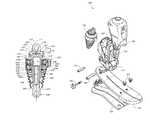
- FIG. 1is a perspective view of a lower limb prosthesis having an ankle-motion-controlled foot unit according to one embodiment of the invention.
- FIG. 2is a perspective view of the lower limb prosthesis of FIG. 1 , wherein a cover is removed to show inner components of the prosthesis.
- FIG. 3is a side view of the lower limb prosthesis of FIG. 2 .
- FIG. 4is a rear view of the lower limb prosthesis of FIG. 2 .
- FIG. 5is a side view of the lower limb prosthesis of FIG. 1 with the cover shown partially removed, wherein the ankle-motion-controlled foot is adjusted to accommodate an incline.
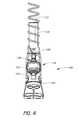
- FIG. 6is a side view of a lower limb prosthesis of FIG. 5 , wherein the ankle-motion-controlled foot is adjusted to accommodate a decline.
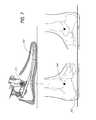
- FIG. 7is a schematic drawing indicating the correlation between an ankle pivot point on an exemplifying embodiment of a prosthetic foot unit with the natural ankle joint of a human foot.
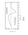
- FIG. 8is a graph depicting the range of ankle motion of an exemplifying embodiment of a prosthetic or orthotic system during one full stride on a level surface.
- FIG. 9is a block diagram of an exemplifying embodiment of a control system architecture of a prosthetic or orthotic system having an ankle-motion-controlled foot.
- FIG. 10is a table illustrating control signals usable to adjust the ankle angle of a prosthetic or orthotic system according to one embodiment of the invention.
- FIG. 11is a graph depicting an exemplifying embodiment of the relationship between the control of a prosthetic or orthotic system and the motion of a corresponding sound limb.
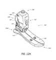
- FIG. 12Ais a perspective view of another embodiment of a lower limb prosthesis.
- FIG. 12Bis a side view of the lower limb prosthesis of FIG. 12A .
- FIG. 12Cis a cross-sectional view of the lower limb prosthesis of FIG. 12B along plane M-M.
- FIG. 13is a perspective view of one embodiment of an actuator which may be used with the lower limb prosthesis of FIG. 12A .
- FIG. 14is a side-view of the actuator of FIG. 13 .
- FIG. 15is a rear view of the actuator of FIG. 13 .
- FIG. 16is a top view of the actuator of FIG. 13 .
- FIG. 17is a cross-sectional side view of the actuator of FIG. 13 .
- FIG. 18is an exploded view of the actuator of FIG. 13 .
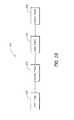
- FIG. 19is a flow chart illustrating different phases of motion of the prosthesis shown in FIG. 12A .
- FIG. 20is a disassembled view of a lower limb prosthesis having an ankle-motion-controlled foot unit according to another embodiment of the invention.
- FIG. 21is a disassembled view of a sensor assembly usable with the lower limb prosthesis of FIG. 20 .
- Some preferred embodiments of the invention described hereinrelate generally to prosthetic and orthotic systems and, in particular, to prosthetic and orthotic devices having an ankle-motion-controlled foot. While the description sets forth various embodiment-specific details, it will be appreciated that the description is illustrative only and should not be construed in any way as limiting the invention. Furthermore, various applications of the invention, and modifications thereto, which may occur to those who are skilled in the art, are also encompassed by the general concepts described herein.
- prostheticand “prosthesis” as used herein are broad terms and are used in their ordinary sense and refer to, without limitation, any system, device or apparatus usable as an artificial substitute or support for a body part.
- orthotic and “orthosis” as used hereinare broad terms and are used in their ordinary sense and refer to, without limitation, any system, device or apparatus usable to support, align, prevent, protect, correct deformities of, immobilize, or improve the function of parts of the body, such as joints and/or limbs.
- ankle deviceas used herein is a broad term and is used in its ordinary sense and relates to any prosthetic, orthotic or ankle-assisting device.
- transtibialas used herein is a broad term and is used in its ordinary sense and relates to without limitation any plane, direction, location, or cross-section that is located at or below a knee joint of a body, including artificial knee joints.
- transfemoralas used herein is a broad term and is used in its ordinary sense and relates to without limitation any plane, direction, location, or cross-section that is located at or above a knee joint of a body, including artificial knee joints.
- sagittalas used herein is a broad term and is used in its ordinary sense and relates to any description, location, or direction relating to, situated in, or being in or near the median plane (i.e., the plane divides the body lengthwise into right and left halves) of the body or any plane parallel or approximately parallel thereto.
- a “sagittal plane”may also refer to any vertical anterior to posterior plane that passes through the body parallel or approximately parallel to the median plane and that divides the body into equal or unequal right and left sections.
- coronalas used herein is a broad term and is used in its ordinary sense and relates to any description, location, or direction relating to, situated in, or being in or near the plane that passes through the long axis of the body.
- a “coronal plane”may also refer to any plane that passes vertically or approximately vertically through the body and is perpendicular or approximately perpendicular to the median plane and that divides the body into anterior and posterior sections.
- FIG. 1illustrates one embodiment of a lower limb prosthesis 100 having an ankle-motion-controlled foot with an attachment member.
- the prosthesis 100comprises an attachment member, in the form of a lower limb member 102 , operatively coupled to a foot unit 104 .
- attachment memberis a broad term and is used in its ordinary sense and in a prosthetic foot embodiment relates to, without limitation, any member that attaches either directly or indirectly to the foot unit 104 and is moveable in relation thereto, for example by a pivoting motion, and is used to attach the prosthesis 100 to a stump or intermediate prosthesis.
- the attachment membermay take the form of a lower limb member in an ankle-prosthesis embodiment.
- the attachment membermay be used to attach to and support a body part, such as with a brace, which also is moveably connected to a second member, such as a foot unit, which would also attach to and support a body part, such as the foot.
- the lower limb member 102is a generally elongated member with a main longitudinal axis that extends in approximately a tibial direction, that is, a direction that extends generally along the axis of a natural tibia bone.
- FIG. 1depicts the lower limb member 102 as being a generally vertical orientation.
- the lower limb member 102may comprise multiple sections.
- the lower limb member 102may comprise two elongated sections that extend approximately parallel in a tibial direction and that are connected together.
- the lower limb member 102comprises a two-sided chamber having two substantially symmetrical parts to form a partially enclosed housing.
- the lower limb member 102may comprise a hollow member, such as a tube-like structure.
- the lower limb member 102may comprise elongated flat portions or rounded portions.
- the structure of the lower limb member 102is not elongated.
- the lower limb member 102may comprise a generally circular, cylindrical, half-circular, dome-shaped, oval or rectangular structure.
- a possible lower limb memberis the ankle module and the structures described in U.S. patent application Ser. No. 10/742,455, filed Dec. 18, 2003, and entitled “PROSTHETIC FOOT WITH ROCKER MEMBER,” the entirety of which is hereby incorporated herein by reference and is to be considered as part of this specification.
- the lower limb member 102is generally formed of a machine metal, such as aluminum, or a carbon fiber material. In other embodiments of the invention, the lower limb member 102 may comprise other materials that are suitable for prosthetic devices. In one embodiment, the lower limb member 102 advantageously has a height between approximately 12 and 15 centimeters. In other embodiments of the invention, the lower limb member 102 may have a height less than 12 centimeters or height greater than 15 centimeters depending on the size of the user and/or the intended use of the prosthesis 100 . For example, the lower limb member 102 may have a height of approximately 20 centimeters.
- the prosthesis 100is configured such that the main longitudinal axis of the lower limb member 102 is substantially perpendicular to a lower surface of the foot unit 104 when the prosthesis 100 is in a resting position.
- the lower limb member 102may be substantially perpendicular to a level ground surface when the foot unit 104 rests on the ground. Such a configuration advantageously provides a user with increased support and/or stability.
- the lower limb member 102further comprises a cover 106 .
- the cover 106houses and/or protects the inner components of the lower limb member 102 .
- the cover 106may be rounded or may be shaped in the form of a natural human leg.
- the lower limb member 102further comprises an attachment portion 108 to facilitate coupling of the lower limb member 102 .
- the attachment portion 108 of the lower limb member 102couples the prosthesis 100 to a pylon 110 .
- the attachment portion 108may be configured to couple the prosthesis 100 to a stump of an amputee or to another prosthetic device.
- FIG. 1also depicts a control wire 112 usable to provide power to and/or communicate control signals to the prosthesis 100 .
- the foot unit 104may comprise various types of prosthetic or orthotic feet. As illustrated in FIG. 1 , the foot unit 104 incorporates a design described in Applicant's co-pending U.S. patent application Ser. No. 10/642,125, entitled “LOW PROFILE PROSTHETIC FOOT,” and filed Aug. 15, 2003 the entirety of which is hereby incorporated by reference and is to be considered as part of this specification.
- the foot unit 104may comprise a standard LP VARI-FLEX® unit available from ⁇ ssur.
- the foot unit 104is configured to exert a proportional response to weight or impact levels on the foot unit 104 .
- the foot unit 104may comprise shock absorption for comfortable loading of the heel and/or for returning expended energy.
- the foot unit 104may comprise a full-length toe lever with enhanced flexibility so as to provide a stride length for the prosthetic limb that mimics the stride length of the healthy limb.
- the foot unit 104may comprise a split-toe configuration, which facilitates movement on uneven terrain.
- the foot unit 104may also include a cosmesis or a foot cover such as, for example, a standard Flex-Foot cover available from ⁇ ssur.
- FIG. 2depicts the prosthesis 100 with the cover 106 removed.
- a lower end of the lower limb member 102is coupled to the foot unit 104 at a pivot assembly 114 .
- the lower limb member 102is coupled to an ankle plate of the foot unit 104 , which extends generally rearward and upward from a toe portion of the foot unit 104 .
- the pivot assembly 114allows for angular movement of the foot unit 104 with respect to the lower limb member 102 .
- the pivot assembly 114advantageously comprises at least one pivot pin.
- the pivot assembly 114comprises a hinge, a multi-axial configuration, a polycentric configuration, combinations of the same or the like.
- the pivot assembly 114is located on a portion of the foot unit 104 that is near a natural ankle location of the foot unit 104 .
- the pivot assembly 114may be bolted or otherwise releasably connected to the foot unit 104 .
- FIG. 2further depicts the prosthesis 100 having an actuator 116 .
- the actuator 116advantageously provides the prosthesis 100 with the necessary energy to execute angular displacements synchronized with the amputee's locomotion.
- the actuator 116may cause the foot unit 104 to move similar to a natural human foot.
- the lower end of the actuator 116is coupled to the foot unit 104 at a first attachment point 118 .
- the foot attachment point 118is advantageously located on the upper surface of the foot unit 104 on a posterior portion thereof.
- the upper end of the actuator 116is coupled to the lower limb member 102 at a second attachment point 120 .
- the linear motion (or extension and contraction) of the actuator 116controls, or actively adjusts, the angle between the foot unit 104 and the lower limb member 102 .
- FIG. 2depicts the actuator 116 comprising a double-screw motor, wherein the motor pushes or pulls a posterior portion of the foot unit 104 with respect to the lower limb member 102 .
- the actuator 116comprises other mechanisms capable of actively adjusting an angle, or providing for motion between, multiple members.
- the actuator 116may comprise a single-screw motor, a piston cylinder-type structure, a servomotor, a stepper motor, a rotary motor, a spring, a fluid actuator, or the like.
- the actuator 116may actively adjust in only one direction, the angle between the lower limb member 102 and the foot unit 104 .
- the weight of the usermay also be used in controlling the angle caused by and/or the movement of the actuator 116 .
- FIG. 2illustrates the actuator 116 in a posterior configuration, wherein the actuator 116 is located behind the lower limb member 102 .
- the actuator 116may be used in an anterior configuration, wherein the actuator 116 is located in front of the lower limb member 102 .
- the actuator 116comprises an auto adjusting ankle structure and incorporates a design, such as described in U.S. Pat. No. 5,957,981, the entirety of which is hereby incorporated by reference and is to be considered as a part of this specification.
- the particular configuration or structuremay be selected to most closely imitate the movement and location of a natural human ankle joint and to facilitate insertion of the prosthesis 100 into an outer cosmesis.
- the actuator 116is advantageously configured to operate so as to not to emit loud noises, such as intermittent noises, perceptible by the user and/or others.
- the actuator 116may also be configured to not operate or adjust if the prosthesis 100 experiences torque, such as in the sagittal plane, that exceeds a certain level. For example, if the torque level exceeds four Newton meters (Nm), the actuator 116 may cease to operate or may issue an alarm.
- NmNewton meters
- the actuator 116may also be substantially enclosed within the cover 106 as shown in FIG. 1 such that the portions of the actuator 116 are not visible and/or exposed to the environment. In another embodiment, the actuator may be at least partially enclosed by the lower limb member 102 .
- FIG. 2further depicts control circuitry 122 usable to control the operation of the actuator 116 and/or the foot unit 104 .
- the control circuitry 122comprises at least one printed circuit board (PCB).
- the PCBmay further comprise a microprocessor.
- Softwaremay also reside on the PCB so as to perform signal processing and/or control the movement of the prosthesis 100 .
- the prosthesis 100includes a battery (not shown) that powers the control circuitry 122 and/or the actuator 116 .
- the batterycomprises a rechargeable lithium ion battery that preferably has a power cycle of at least 12 to 16 hours. In yet other embodiments, the power cycle of the battery may be less than 12 hours or may be more than 16 hours.
- the batterycomprises a lithium polymer battery, fuel cell technology, or other types of batteries or technology usable to provide power to the prosthesis 100 .
- the batteryis removably attached to a rear surface of the lower limb member 102 , to other portions of the prosthesis 100 , or is located remote the prosthesis 100 .
- the prosthesis 100may be connected to an external power source, such as through a wall adapter or car adapter, to recharge the battery.
- the prosthesis 100is configured to lock in a neutral position, such as the lower limb member 102 being aligned generally vertical relative to a level ground surface when the foot unit 104 is resting on the level ground surface, when the battery is out of power or enters a low power stage. Such locking provides for operational safety, reliability, and/or stability for a user.
- the prosthesis 100may also provide a battery status display that alerts the user as to the status (i.e., charge) of the battery.
- the prosthesis 100locks into a substantially neutral position when the motion control functions of the prosthesis 100 are turned off or disabled by a user.
- a cosmesis material or other dressingsmay be used with the prosthesis 100 so as to give the prosthesis 100 a more natural look or shape.
- the cosmesis, dressings, or other filler materialmay be used to prevent contaminants, such as dirt or water, from contacting the components of the prosthesis 100 .
- FIG. 3depicts a side view of the prosthesis 100 according to one embodiment of the invention.
- the actuator 116further comprises a main housing 124 , a lower extendable portion 126 , and an upper extendable portion 128 .
- the lower extendable portion 126couples the main housing 124 of the actuator 116 to the foot unit 104 at the first attachment point 118 .
- the upper extendable portion 128couples the main housing 124 of the actuator 116 to the lower limb member 102 at the second attachment point 120 .
- the lower extendable portion 126 and/or the upper extendable portion 128move into and/or out of the main housing 124 of the actuator 116 to adjust an angle between the foot unit 104 and the lower limb member 102 .
- the actuator 116causes the lower extendable portion 126 and/or the upper extendable portion 128 to contract or withdraw into the main housing 124 .
- at least one of the extendable portions 126 , 128may have a threaded surface such that rotation in one direction (e.g., clockwise) causes the extendable portion to withdraw into the main housing 124 of the actuator.
- at least one of the extendable portions 126 , 128comprises multiple telescoping pieces such that, upon contraction, one of the multiple pieces of extendable portion contracts into another of the multiple pieces without withdrawing into the main housing 124 .
- the lower extendable portion 126 and/or the upper extendable portion 128may extend from the main housing 124 .
- extension of the lower extendable portion 126 and/or the upper extendable portion 128causes an increase in the angle between the lower limb member 102 and the foot unit 104 .
- a contraction of the lower extendable portion 126 and/or the upper extendable portion 128causes a decrease in the angle between the foot unit 104 and the lower limb member 102 .
- FIG. 4illustrates a rear view of the prosthesis 100 depicted in FIGS. 1-3 .
- the cover 106extends around the posterior portion of the prosthesis 100 to house at least a portion of the actuator 116 such that portions of the actuator 116 are not visible and/or not exposed to the environment.
- FIGS. 5 and 6illustrate one embodiment of the prosthesis 100 as it adjusts to inclines and declines.
- the prosthesis 100is depicted as adjusting to an incline.
- the actuator 116extends so as to decrease an angle ⁇ between the lower limb member 102 and the foot unit 104 (or “dorsiflexion”).
- ⁇an angle between the lower limb member 102 and the foot unit 104
- the angular range of motion of the prosthesis 100is from about 0 to 10 degrees from the neutral position. Other embodiments may also facilitate exaggerated dorsiflexion during swing phase.
- FIG. 6illustrates the prosthesis 100 as it adjusts to a decline.
- the actuator 116extends so as to increase the angle ⁇ between the lower limb member 102 and the foot unit 104 (or “plantarflexion”).
- plantarflexionin one embodiment, the angular range of motion of the prosthesis 100 is from about 0 to 20 degrees from the neutral position. Such plantarflexion mimics natural ankle movement and provides for greater stability to an amputee or a user.
- the total range of motion about the ankle pivot axis of the prosthesis 100is approximately 30 degrees or more.
- the motion-controlled foot of the prosthesis 100advantageously accommodates different terrain, operates while traveling up and down stairs, and facilitates level ground walking.
- the prosthesis 100may provide for automatic heel height adjustability. Heel height may be measured, in one embodiment, from an ankle portion of the lower limb member 102 to a ground surface when the foot unit 104 is generally flat to the ground. For example, a user may adjust to various heel heights, such as through pressing one or more buttons, such that the prosthesis 100 automatically aligns itself to the appropriate heel height.
- the prosthesis 100includes a plurality of predetermined heel heights. In yet other embodiments, the prosthesis 100 may automatically adjust the heel height without the need for user input.
- FIGS. 5 and 6further illustrate one embodiment of the attachment portion 108 .
- the attachment portion 108provides alignment between the natural limb of the amputee and the prosthesis 100 and may be configured so as to decrease pressure peaks and shear forces.
- the attachment portion 108may be configured to attach to another prosthesis, to the stump of the amputee, or to another component.
- the attachment portion 108comprises a socket connector.
- the socket connectormay be configured to receive a 32 mm-thread component, a male pyramid type coupler, or other components.
- the attachment portion 108may also comprise, or be configured to receive, a female pyramid adapter.
- FIG. 7further illustrates a schematic drawing indicating the correlation between an ankle pivot point on a prosthetic foot unit 204 with the natural human ankle joint of a foot.
- the prosthetic foot unit 204comprises a pivot assembly 214 that corresponds to an ankle joint 240 of a human foot 242 .
- the pivot assembly 114is located near the mechanical ankle center of rotation of the prosthesis 100 .
- FIG. 8illustrates a graph depicting the possible range of ankle motion of an embodiment of the prosthesis 100 during one full stride on a level surface.
- the x-axis of the graphrepresents various points during one full stride of a user (i.e., 0 to 100 percent).
- the y-axisrepresents the ankle angle ( ⁇ ) of the prosthesis 100 .
- the ankle angle ( ⁇ )varies from approximately 20 degrees plantarflexion (i.e., neutral position angle +20 degrees) to approximately 10 degrees dorsiflexion (i.e., neutral position angle ⁇ 20 degrees).
- the prosthesis 100is configured to provide dampening or passive, soft resistance to changes in the angle between the lower limb member 102 and the foot unit 104 .
- An example of a system for controlling such dampeningis disclosed in U.S. Pat. No. 6,443,993, which is hereby incorporated herein by reference and is to be considered as a part of this specification.
- dampening of the prosthesis 100may be provided by hydraulic dampers.
- other components or devices that are known in the artmay be used to provide dampening for the prosthesis 100 .
- the dampersmay be dynamically controlled, such as through an electronic control system, which is discussed in more detail below.
- the dampersmay be controlled through mechanical and/or fluid-type structures.
- an orthotic systemmay comprise at least one actuator that actively controls the angle of an orthosis that is used with an injured or debilitated ankle.
- the orthotic systemmay, in addition to the electronic control of the orthotic system, provide for the user's control or natural movement of the injured ankle or leg.
- the above-described systemsmay be implemented in prosthetic or orthotic systems other than transtibial, or below-the-knee, systems.
- the prosthetic or orthotic systemmay be used in a transfemoral, or above-the-knee, system, such as is disclosed in U.S. Provisional Application No. 60/569,512, filed May 7, 2004, and entitled “MAGNETORHEOLOGICALLY ACTUATED PROSTHETIC KNEE;” U.S. Provisional Application No. 60/624,986, filed Nov. 3, 2004, and entitled “MAGNETORHEOLOGICALLY ACTUATED PROSTHETIC KNEE;” and U.S. patent application Ser. No.
- the prosthetic or orthotic systemmay include both a prosthetic or orthotic ankle and/or a prosthetic or orthotic knee.
- FIG. 9illustrates a block diagram of one embodiment of a system architecture of a control system 300 for an ankle-motion-controlled foot.
- the control system 300is usable by the lower limb prosthesis 100 depicted in FIGS. 1-6 .
- the control system 300is usable by an orthotic system or a rehabilitation system having an ankle-motion-controlled foot, or other motion-controlled limb.
- the control system 300is based on a distributed processing system wherein the different functions performed by the prosthetic or orthotic system, such as sensing, data processing, and actuation, are performed or controlled by multiple processors that communicate with each other.
- the control system 300includes a sensor module 302 , an ankle device 304 (such as, for example, the prosthesis 100 depicted in FIG. 1 ), a central processing unit (“CPU”) 305 , a memory 306 , an interface module 308 , a control drive module 310 , an actuator 316 and a power module 318 .
- a sensor module 302such as, for example, the prosthesis 100 depicted in FIG. 1
- a central processing unit (“CPU”) 305such as, for example, the prosthesis 100 depicted in FIG. 1
- CPUcentral processing unit
- the control system 300 depicted in FIG. 9processes data received from the sensing module 302 with the CPU 305 .
- the CPU 305communicates with the control drive module 310 to control the operation of the actuator 316 so as to mimic natural ankle movement by the ankle device 304 .
- the control system 300may predict how the ankle device 304 may need to be adjusted in order to accommodate movement by the user.
- the CPU 305may also receive commands from a user and/or other device through the interface module 308 .
- the power module 318provides power to the other components of the control system 300 . Each of these components is described in more detail below.
- the sensor module 302is used to measure variables relating to the ankle device 304 , such as the position and/or the movement of the ankle device 304 throughout a gait cycle.
- the sensor module 320is advantageously located on the ankle device 304 .
- the sensor module 302may be located near a mechanical ankle center of rotation of the ankle device 304 , such as the pivot assembly 114 of the prosthesis 100 depicted in FIG. 2 .
- the sensor module 302may be located on the user's natural limb that is attached to, or associated with, the ankle device 304 .
- the sensorsare used to capture information relating to the movement of the natural limb on the user's ankle-device side to adjust the ankle device 304 .
- the sensor module 302advantageously includes a printed circuit board housing, multiple sensors, such as accelerometers, which each measures an acceleration of the ankle device 304 in a different axis.
- the sensor module 302may comprise three accelerometers that measure acceleration of the ankle device 304 in three substantially, mutually perpendicular axes. Sensors of the type suitable for the sensor module 302 are available from, for example, Dynastream Innovations, Inc. (Alberta, Canada).
- the sensor module 302may include one or more other types of sensors in combination with, or in place of, accelerometers.
- the sensor module 302may include a gyroscope configured to measure the angular speed of body segments and/or the ankle device 304 .
- the sensor module 302includes a plantar pressure sensor configured to measure, for example, the vertical plantar pressure of a specific underfoot area.
- the sensor module 302may include one or more of the following: kinematic sensors, single-axis gyroscopes, single- or multi-axis accelerometers, load sensors, flex sensors or myoelectric sensors that may be configured to capture data from the user's natural limb.
- the sensor module 302may be used to capture information relating to, for example, one or more of the following: the position of the ankle device 304 with respect to the ground; the inclination angle of the ankle device 304 ; the direction of gravity with respect to the position of the ankle device 304 ; information that relates to a stride of the user, such as when the ankle device 304 contacts the ground (e.g., “heel strike”), is in mid-stride, or leaves the ground (e.g., “toe-off”), the distance from the ground of the prosthesis 100 at the peak of the swing phase (i.e., the maximum height during the swing phase); the timing of the peak of the swing phase; and the like.
- a stride of the usersuch as when the ankle device 304 contacts the ground (e.g., “heel strike”), is in mid-stride, or leaves the ground (e.g., “toe-off”), the distance from the ground of the prosthesis 100 at the peak of the swing phase (i.
- the sensor module 302is configured to detect gait patterns and/or events. For example, the sensor module 302 may determine whether the user is in a standing/stopped position, is walking on level ground, is ascending and/or descending stairs or sloped surfaces, or the like. In other embodiments, the sensor module 302 is configured to detect or measure the heel height of the ankle device 304 and/or determine a static shank angle in order to detect when the user is in a sitting position.
- the sensor module 302is further configured to measure environmental or terrain variables including one or more of the following: the characteristics of the ground surface, the angle of the ground surface, the air temperature and wind resistance.
- the measured temperaturemay be used to calibrate the gain and/or bias of other sensors.
- the sensor module 302captures information about the movement and/or position of a user's natural limb, such as a healthy leg. In such an embodiment, it may be preferable that when operating on an incline or a decline, the first step of the user be taken with the healthy leg. Such would allow measurements taken from the natural movement of the healthy leg prior to adjusting the ankle device 304 .
- the control system 300detects the gait of the user and adjusts the ankle device 304 accordingly while the ankle device 304 is in a swing phase of the first step. In other embodiments of the invention, there may be a latency period in which the control system 300 requires one or two strides before being able to accurately determine the gait of the user and to adjust the ankle device 304 appropriately.
- the sensor module 302has a default sampling rate of 100 hertz (Hz). In other embodiments, the sampling rate may be higher or lower than 100 Hz or may be adjustable by a user, or may be adjusted automatically by software or parameter settings. In addition, the sensor module 302 may provide for synchronization between types of data being sensed or include time stamping. The sensors may also be configured so as to have an angular resolution of approximately 0.5 degrees, allowing for fine adjustments of the ankle device 304 .
- the sensor module 302is configured to power down into a “sleep” mode when sensing is not needed, such as for example, when the user is relaxing while in a sitting or reclining position. In such an embodiment, the sensor module 302 may awake from the sleep state upon movement of the sensor module 302 or upon input from the user. In one embodiment, the sensor module 302 consumes approximately 30 milliamps (mA) when in an “active” mode and approximately 0.1 mA when in a “sleep” mode.
- mAmilliamps
- FIG. 9illustrates the sensor module 302 communicating with the CPU 305 .
- the sensor module 302advantageously provides measurement data to the CPU 305 and/or to other components of the control system 300 .
- the sensor module 302is coupled to a transmitter, such as, for example, a Bluetooth® transmitter, that transmits the measurements to the CPU 305 .
- a transmittersuch as, for example, a Bluetooth® transmitter
- other types of transmitters or wireless technologymay be used, such as infrared, WiFi®, or radio frequency (RF) technology.
- RFradio frequency
- wired technologiesmay be used to communicate with the CPU 305 .
- the sensor module 302sends a data string to the CPU 305 that comprises various types of information.
- the data stringmay comprise 160 bits and include the following information:
- TSTimestamp
- AccXlinear acceleration of foot along X axis
- AccYlinear acceleration of foot along Y axis
- AccZlinear acceleration of foot along Z axis
- GyroXangular acceleration of foot along X axis
- GyroYangular acceleration of foot along Y axis
- GyroZangular acceleration of foot along Z axis
- DegXfoot inclination angle in coronal plane
- DegYfoot inclination angle in sagittal plane
- FSlogic state of switches in the ankle device 304
- Morientation of the sensors.
- other lengths of data stringscomprising more or less information may be used.
- the CPU 305advantageously processes data received from other components of the control system 300 .
- the CPU 305processes information relating to the gait of the user, such as information received from the sensor module 302 , determines locomotion type (i.e., gait pattern), and/or sends commands to the control drive module 310 .
- the data captured by the sensor module 302may be used to generate a waveform that portrays information relating to the gait or movement of the user. Subsequent changes to the waveform may be identified by the CPU 305 to predict future movement of the user and to adjust the ankle device 304 accordingly.
- the CPU 305may detect gait patterns from as slow as 20 steps per minute to as high as 125 steps per minute. In other embodiments of the invention, the CPU 305 may detect gait patterns that are slower than 20 steps per minute or higher than 125 steps per minute.
- the CPU 305processes data relating to state transitions according to the following table (TABLE 1).
- TABLE 1shows possible state transitions usable with the control system 300 .
- the first column of TABLE 1lists possible initial states of the ankle device 304 , and the first row lists possible second states of the ankle device 304 .
- the body of TABLE 1identifies the source of data used by the CPU 305 in controlling, or actively adjusting, the actuator 316 and the ankle device 304 during the transition from a first state to a second state; wherein “N” indicates that no additional data is needed for the state transition; “L” indicates that the CPU 305 uses transition logic to determine the adjustments to the ankle device 304 during the state transition; and “I” indicates the CPU receives data from an interface (e.g., interface module 308 , external user interface, electronic interface or the like).
- Transition logic usable with embodiments of the inventionmay be developed by one with ordinary skill in the relevant art. Examples of transition logic used in similar systems and methods to embodiments of the present invention are disclosed in U.S. Provisional Application No.
- the above described states in TABLE 1are predefined states of the ankle device 304 .
- the “OFF” statemay indicate that the functions of the ankle device 304 and the actuator 316 are in an off or suspend mode.
- the “HEEL_HEIGHT_CAL” staterelates to the measuring of a heel height from a static sensor angle such as, for example, when the ankle device 304 is not in motion.
- the “SENSOR_CAL” staterelates to surface angle calibration when the user is walking on a level surface.
- the “NEUTRAL” staterelates to when the ankle device 304 is locked in a substantially fixed position.
- the “WALK” staterelates to when the user is walking, such as on a level or sloped surface.
- the “STAIRS_UP” and “STAIRS_DOWN” statesrelate to when the user is walking, respectively, up and down stairs.
- the “RELAX” staterelates to when the user is in a relaxed position.
- the “RELAX” staterelates to when a user is in a sitting position with the limb having the ankle device 304 crossed over the other limb.
- the control system 300may cause the ankle device 304 to move into a maximum plantarflexion position to mimic, for example, the natural position and/or look of a healthy foot.
- the “PANTS” staterelates to when a user is putting on pants, trousers, shorts or the like. In such a state, the control system 300 may, in one embodiment, cause the ankle device 304 to move into a maximum plantarflexion position to facilitate putting the clothing on over the ankle device 304 .
- other statesare usable with the ankle device 304 in place of, or in combination with, the states identified in TABLE 1.
- statesmay be defined that correspond to lying down, cycling, climbing a ladder or the like.
- the CPU 305 and/or control system 300may process or derive data from sources other than those listed in TABLE 1.
- the CPU 305may perform a variety of other functions.
- the CPU 305may use information received from the sensor module 302 to detect stumbling by the user.
- the CPU 305may function as a manager of communication between the components of the control system 300 .
- the CPU 305may act as the master device for a communication bus between multiple components of the control system 300 .
- the CPU 305communicates with the power module 318 .
- the CPU 305may provide power distribution and/or conversion to the other components of the control system 300 and may also monitor battery power or battery life.
- the CPU 305may function so as to temporarily suspend or decrease power to the control system 300 when a user is in a sitting or a standing position.
- the CPU 305may also process error handling, such as when communication fails between components, an unrecognized signal or waveform is received from the sensor module 302 , or when the feedback from the control drive module 310 or the ankle device 304 causes an error or appears corrupt.
- the CPU 305uses or computes a security factor when analyzing information from the sensor module 302 and/or sending commands to the control drive module 310 .
- the security factormay include a range of values, wherein a higher value indicates a higher degree of certainty associated with a determined locomotion type of the user, and a lower security factor indicates a lower degree of certainty as to the locomotion type of the user.
- adjustmentsare not made to the ankle device 304 unless the locomotion type of the user is recognized with a security factor above a predetermined threshold value.
- the CPU 305includes modules that comprise logic embodied in hardware or firmware, or that comprise a collection of software instructions written in a programming language, such as, for example C++.
- a software modulemay be compiled and linked into an executable program, installed in a dynamic link library, or may be written in an interpretive language such as BASIC.
- software modulesmay be callable from other modules or from themselves, and/or may be invoked in response to detected events or interrupts.
- Software instructionsmay be embedded in firmware, such as an EPROM or EEPROM.
- hardware modulesmay be comprised of connected logic units, such as gates and flip-flops, and/or may be comprised of programmable units, such as programmable gate arrays or processors.
- FIG. 9further depicts CPU 305 including a memory 306 for storing instructions and/or data.
- the memory 306may store one or more of the following types of data or instructions: an error log for the other components of the control system 300 ; information regarding gait patterns or curves; information regarding past activity of the user (e.g., number of steps); control parameters and set points; information regarding software debugging or upgrading; preprogrammed algorithms for basic movements of the prosthetic or orthotic system; calibration values and parameters relating to the sensor module 302 or other components; instructions downloaded from an external device; combinations of the same or the like.
- the memory 306may comprise any buffer, computing device, or system capable of storing computer instructions and/or data for access by another computing device or a computer processor.
- the memory 306is a cache that is part of the CPU 305 .
- the memory 306is separate from the CPU 305 .
- the memory 306comprises random access memory (RAM) or may comprise other integrated and accessible memory devices, such as, for example, read-only memory (ROM), programmable ROM (PROM), and electrically erasable programmable ROM (EEPROM).
- the memory 306comprises a removable memory, such as a memory card, a removable drive, or the like.
- the CPU 305may also be configured to receive through the interface module 308 user- or activity-specific instructions from a user or from an external device.
- the CPU 305may also receive updates to already existing instructions.
- the CPU 305may communicate with a personal computer, a personal digital assistant, or the like so as to download or receive operating instructions.
- Activity-specific instructionsmay include, for example, data relating to cycling, driving, ascending or descending a ladder, adjustments from walking in snow or sand, or the like.
- the interface module 308comprises an interface that the user accesses so as to control or manage portions or functions of the prosthetic or orthotic system.
- the interface module 308is a flexible keypad having multiple buttons and/or multiple light emitting diodes (LEDs) usable to receive information from and/or convey information to a user.
- the LEDsmay indicate the status of a battery or may convey a confirmation signal to a user.
- the interface module 308may be advantageously located on the ankle device 304 .
- the interface module 308may comprise a USB connector usable for communication to an external computing device, such as a personal computer.
- the interface module 308comprises an on/off switch.
- the interface module 308may receive input regarding the user-controlled heel height or a forced relaxed mode of the prosthetic or orthotic system.
- the usermay adjust the type of response desired of the prosthesis or enable/disable particular functions of the ankle device 304 .
- the input from the usermay be entered directly via the interface module 308 , such as through actuating a button, or user input may be received via a remote control.
- the interface module 308may comprise a touch screen, buttons, switches, a vibrator, an alarm, or other input-receiving or output structures or devices that allow a user to send instructions to or receive information from the control system 300 .
- the interface module 308comprises an additional structure, such as a plug, for charging a battery powering the control system 300 , such as at home or in a vehicle.
- the interface module 308may also communicate directly or indirectly with components of the control system 300 other than the CPU 305 .
- the control drive module 310is used to translate high-level plans or instructions received from the CPU 305 into low-level control signals to be sent to the actuator 316 .
- the control drive module 310comprises a printed circuit board that implements control algorithms and tasks related to the management of the actuator 316 .
- the control drive module 310may be used to implement a hardware abstraction layer that translates the decision processes of the CPU 305 to the actual hardware definition of the actuator 316 .
- the control drive module 310may be used to provide feedback to the CPU 305 regarding the position or movement of the actuator 316 or ankle device 304 .
- the control drive module 310may also be used to adjust the actuator 316 to a new “neutral” setting upon detection by the CPU 305 that the user is traveling on an angled surface.
- control drive module 310is located within the ankle device 304 . In other embodiments, the control drive module 310 may be located on the outside of the ankle device 304 , such as on a socket, or remote to the ankle device 304 .
- the actuator 316provides for the controlled movement of the ankle device 304 .
- the actuator 316functions similarly to the actuator 116 described with respect to FIGS. 1-6 , which actuator 116 controls the ankle motion of the prosthesis 100 .
- the actuator 316may be configured to control the motion of an orthotic device, such as a brace or other type of support structure.
- the ankle device 304comprises any structural device that is used to mimic the motion of a joint, such as an ankle, and that is controlled, at least in part, by the actuator 316 .
- the ankle device 304may comprise a prosthetic device or an orthotic device.
- the power module 318includes one or more sources and/or connectors usable to power the control system 300 .
- the power module 318is advantageously portable, and may include, for example, a rechargeable battery, as discussed previously.
- the power module 318communicates with the control drive module 310 and the CPU 305 .
- the power module 318communicates with other control system 300 components instead of, or in combination with, the control drive module 310 and the CPU 305 .
- the power module 318communicates directly with the sensor module 302 .
- the power module 318may communicate with the interface module 308 such that a user is capable of directly controlling the power supplied to one or more components of the control system 300 .
- FIG. 9depicts two types of links: primary communication links, which are depicted as solid lines between the components, and secondary communication links, which are depicted as dashed lines.
- primary communication linksoperate on an established protocol.
- the primary communication linksmay run between physical components of the control system 300 .
- Secondary communication linksmay operate on a different protocol or level than the primary communication links. For example, if a conflict exists between a primary communication link and a secondary communication link, the data from the primary communication link will override the data from the secondary communication link.
- the secondary communication linksare shown in FIG. 9 as being communication channels between the control system 300 and the environment.
- the modulesmay communicate with each other and/or the environment through other types of communication links or methods. For example, all communication links may operate with the same protocol or on the same level of hierarchy.
- the components of the control system 300may be integrated in different forms.
- the componentscan be separated into several subcomponents or can be separated into more devices that reside at different locations and that communicate with each other, such as through a wired or wireless network.
- the modulesmay communicate through RS232 or serial peripheral interface (SPI) channels. Multiple components may also be combined into a single component. It is also contemplated that the components described herein may be integrated into a fewer number of modules. One module may also be separated into multiple modules.
- control system 300may include more or fewer components than described above.
- the control system 300may further include an actuator potentiometer usable to control, or fine-tune, the position of the actuator 316 .
- the usermay also use the actuator potentiometer to adjust the heel height of the ankle device 304 .
- the actuator potentiometercommunicates with the CPU 305 .
- the control system 300may include a vibrator, a DC jack, fuses, combinations of the same, or the like.
- FIG. 10is a table that depicts possible control signals that may be involved in adjusting the ankle angle of a prosthetic or orthotic device when a user is transitioning between different states, or types of locomotion, according to one embodiment of the invention.
- the states listed in a column 402identify a first state of the user
- the states listed in a row 404identify a second state of the user, or the state to which the user is transitioning.
- the remainder of the tableidentifies possible actions that may be taken by the prosthetic or orthotic device with respect to the ankle angle.
- “User set point”is the neutral, or default, value that may be set during shoe heel height adjustment.
- the angles specifiedare examples of changes to the ankle angle of the prosthetic or orthotic device.
- the ankle anglemay be adjusted to the angle of the stairs, such as for example, ⁇ 10 degrees (or 10 degrees dorsiflexion).
- Ankle angles given in the “Incline (up)” and “Decline” columnsreflect threshold levels of ankle angle adjustment depending on the angle of the incline.
- the following tableillustrates possible ankle motion strategies for one embodiment of the invention.
- the first column of TABLE 2lists different types of locomotion types or gait patterns that may be frequently detected.
- the second column of TABLE 2identifies examples of ankle angle adjustment of the prosthetic or orthotic device during the swing phase of each of the identified locomotion types.
- Ankle adjusts to dorsiflexione.g., 7.5°
- Descending StairsAnkle adjusts to dorsiflexion (e.g., 5°)
- Inclineup
- FIG. 11depicts a graph that illustrates the interaction and relationship between the control of a prosthetic or orthotic leg and the measurements taken from a healthy, sound leg.
- FIG. 11depicts the movement of a prosthetic or orthotic leg and a healthy leg during one full stride of a user.
- the graphshows the prosthetic or orthotic leg as being in a “stance” position or being planted on a surface, such as the ground.
- the ankle angle of the prosthetic or orthotic legmay decrease (dorsiflexion).
- the ankle angle of the prosthetic or orthotic legmay then increase (plantarflexion) to facilitate natural stride movements.
- the ankle angle of the prosthetic or orthotic legis not actively adjusted during the stance phase.
- the healthy legmay be in a swinging position, wherein the healthy leg is not in contact with the ground. Between the points of approximately 40% and 60%, both legs are in contact with the ground.
- the prosthetic or orthotic legis in a swinging position, and the healthy leg is in contact with the ground.
- the graph in FIG. 11shows that the ankle angle of the prosthetic or orthotic leg is adjusted during the swing phase. This angle adjustment may be based on previous measurements of the healthy leg during the swing phase of the healthy leg. In one embodiment, during the beginning portion of the swing phase of the prosthetic or orthotic leg, the ankle angle of the prosthetic or orthotic leg may decrease. This allows, for example, a toe portion of the prosthetic or orthotic leg to clear stairs. Toward the latter portion of the swing phase of the prosthetic or orthotic leg, the ankle angle of the prosthetic or orthotic leg may then increase before contacting the ground. In other embodiments, the angle adjustment is based on readings taken by sensors on the prosthetic side.
- FIG. 11is illustrative of the functioning of one embodiment of the invention under certain conditions. Other embodiments or circumstances may require a longer or shorter stance or swing phase and require other adjustments to the angle of the ankle portion of the prosthetic leg.
- FIGS. 12A-12Cillustrate another embodiment of a lower limb prosthesis 100 ′ configured to be attached to a human limb.
- the lower limb prosthesis 100 ′is similar to the lower limb prosthesis 100 illustrated in FIG. 2 , except as noted below.
- the reference numerals used to designate the various components of the lower limb prosthesis 100 ′are identical to those used for identifying the corresponding components of the lower limb prosthesis 100 in FIG. 2 , except that a “′” has been added to the reference numerals.
- the lower limb prosthesis 100 ′comprises a first portion 102 ′ coupled to a second portion 104 ′, wherein the portions 102 ′, 104 ′ are moveable relative to each other to mimic a natural human joint.
- the first portionis a lower limb member 102 ′ and the second portion is a prosthetic foot unit 104 ′ operatively coupled to the lower limb member 102 ′ to mimic a natural human ankle joint.
- the foot unit 104 ′includes a heel portion 104 a ′ at a rear end of the foot unit 104 ′ and a toe portion 104 b ′ at a front end of the foot unit 104 ′.
- the heel and toe portions 104 a ′, 104 b ′can be unitary. In another embodiment, the heel and toe portions 104 a ′, 104 b ′ can be separate components fastened to each other via, for example, bolts, screws, adhesives and the like.
- the prosthetic foot unit 104 ′is an LP VARI-FLEX® prosthetic foot commercially available from ⁇ ssur. However, the foot unit 104 ′ can have other configurations or designs.
- the first and second portionscan be an upper leg member and a lower leg member, respectively, which are coupled to mimic a natural human knee joint.
- the lower limb prosthesis 100 ′may also comprise a frame 106 ′ extending between the foot unit 104 ′ and the lower limb member 102 ′.
- an attachment portion 108 ′ of the lower limb member 102 ′facilitates the coupling of the lower limb member 102 ′ to another member, such as, for example, the pylon 110 depicted in FIGS. 1-4 .
- the attachment portion 108 ′is a pyramid.
- the lower limb member 102 ′, or support membercouples to the foot unit 104 ′ at its lower end via a pivot assembly 114 ′, which is attached to the prosthetic foot unit 104 ′.
- the pivot assembly 114 ′is attached at about the rear 1 ⁇ 3 of the foot unit 104 ′.
- the pivot assembly 114 ′can be attached at other locations on the foot unit 104 ′.
- the pivot assembly 114 ′mimics a natural human ankle joint.
- a cover 106 b ′is disposed about an actuator 500 of the lower limb prosthesis 100 ′ to substantially protect the actuator 500 and inhibit the intrusion of foreign matter.
- the lower limb prosthesis 100 ′may also include a control wire, such as the control wire 112 depicted in FIGS. 1-4 , to provide power to and/or communicates control signals to the prosthesis 100 ′.
- the actuator 500provides the prosthesis 100 ′ with the necessary energy to execute angular displacements synchronized with an amputee's locomotion.
- the actuator 500couples the first and second portions 102 ′, 104 ′ of the prosthesis 100 ′ together, which in the illustrated embodiment correspond to the lower limb member 102 ′ and the prosthetic foot unit 104 ′.
- the actuatoris configured to adjust an angle between the lower limb member 102 ′ and the foot unit 104 ′.
- the actuator 500couples to the foot unit 104 ′ and the lower limb member 102 ′ at first and second attachment points 118 ′, 120 ′, respectively.
- the prosthesiscan include control circuitry to control the operation of the actuator 500 , such as, for example, the control circuitry 122 depicted in FIGS. 2 and 3 .
- FIGS. 13-18illustrate one embodiment of an actuator 500 that may be used with the lower limb prosthesis 100 ′ discussed above.
- the actuator 500preferably comprises a stator or top unit 510 having an attachment end 512 and a bottom end 514 .
- the attachment end 512is a C-shaped clamp (see FIG. 15 ) having a first opening 512 a and a second opening 512 b aligned along a first axis X 1 that extends generally perpendicular to a longitudinal axis Y of the actuator 500 .
- the attachment end 512can have other suitable configurations.
- the openings 512 a , 512 bare preferably sized to receive a fastener therethrough, such as a bolt, screw, or pin (not shown), to allow the top unit 510 to be fastened to, for example, the upper end of the lower limb member 102 ′ at the second attachment point 120 ′.
- a fastenersuch as a bolt, screw, or pin (not shown)
- the bottom end 514 of the top unit 510preferably has a circumferential wall 514 a and a bottom surface 516 .
- the bottom surface 516curves from the circumferential wall 514 a toward a center of the bottom surface 516 .
- the bottom surface 516preferably includes a recess portion 518 located generally at the center of the bottom surface 516 .
- the recess portion 518 on the bottom surface 516 of the top unit 510is preferably sized to receive a ball bearing 522 therein, as further discussed below.
- the circumferential wall 514 aincludes a protrusion 520 that extends outward from the wall 514 a .
- the protrusion 520extends substantially along the entire circumference of the wall 514 a .
- the protrusion 520can be a plurality of protrusions positioned at discrete locations about the circumference of the wall 514 a.
- the actuator 500also comprises a first elongate member or rotor 530 with a body extending from a top end 530 a to a bottom end 530 b along a length 532 , and having a diameter 534 .
- the length 532is between about 25 mm and about 70 mm.
- the diameter 534is between about 12 mm and about 40 mm. More preferably, the diameter 534 is about 17 mm.
- the rotor 530has a circumferential flange 536 at the top end 530 a , the flange 536 having a diameter greater than the diameter 534 of the body.
- the top end 530 ahas an outer surface 537 that curves generally upward from the circumferential flange toward a center 537 a of the surface 537 .
- the surface 537defines a recessed portion 538 generally disposed at the center 537 a thereof.
- the recessed portion 538is preferably contoured to receive the ball bearing 522 therein, such that the ball bearing 522 couples the top unit 510 to the rotor 530 .
- the top unit 510 and the rotor 530couple to each other solely via the ball bearing 522 .
- the ball bearing 522is a single ball bearing. However, other suitable bearings can be used.
- a thrust bearingis disposed between the top unit 510 and the rotor 530 .
- the rotor 530is preferably an elongate nut defining a hollow central portion 539 , which defines a wall 539 a with threads 540 disposed along at least a portion the length of the wall 539 a.
- the ball bearing 522preferably couples the top unit 510 to the first elongate member 530 .
- the curvature of the surface 537 of the rotor 530 and the curvature of the bottom surface 516 of the top unit 510define a gap 541 therebetween.
- the gap 541extends preferably circumferentially about the center 537 a of the surface 537 .
- at least one magnet 542is disposed in the gap 541 and attached to the surface 537 via, for example, an adhesive.
- a plurality of magnets 542are disposed about the center 537 a of the surface 537 .
- an annular magnet(not shown) can be disposed on the surface 537 , with the annulus of the magnet aligned with the center 537 a .
- the magnets 542are preferably configured to exert a magnetic force on the top unit 510 and the rotor 530 , so that the force draws the top unit 510 and the rotor 530 toward each other.
- the actuator 500also includes a retainer 550 having a height 551 and a wall 552 defining an inner diameter 554 .
- the retainer 550includes a flange 556 having an inner portion 556 a extending radially inward from the wall 552 and an outer portion 556 b extending radially outward from the wall 522 , wherein the inner and outer portions 556 a , 556 b are preferably disposed at a bottom end of the wall 552 .
- the illustrated embodimentshows the flange 556 as being continuous around the circumference of the retainer 550
- the flange 556can instead be a plurality of flange members disposed at discrete locations about the circumference of the retainer 556 .
- the inner diameter 554 of the retainer 550is sized to receive the rotor 530 and the top unit 510 therein.
- the inner diameter 554 of the retainer 550is preferably at least slightly greater than the diameter of the flange 536 of the rotor 530 , so that the flange 536 of the rotor 530 does not engage the wall 552 of the retainer 550 .
- the inner diameter 554 of the retainer 550is preferably at least slightly greater than the diameter of at least a portion of the circumferential wall 514 a of the top unit 510 .
- the protrusions 520 on the circumferential wall 514 a of the top unit 510preferably engage a portion of the wall 552 of the retainer 550 , such that the top unit 510 and the retainer 550 are coupled to each other.
- rotor 530rotates about, and translates along, the longitudinal axis Y, as further discussed below.
- the rotor 530remains coupled to the top unit 510 via the ball bearing 522 , but selectively moves in and out of contact with the retainer 550 via the inner flange 556 a , as further described below.
- the rotor 530moves between contact with the top unit 510 , via the ball bearing 522 , and contact with the retainer 550 via the inner flange 556 a.
- a first magnet 560 a and a second magnet 560 bare disposed about a portion of the rotor 530 .
- the first and second magnets 560 a , 560 bpreferably have a height 562 a , 562 b and an inner diameter 564 a , 564 b larger than the diameter 534 of the rotor 530 , so that the magnets 560 a , 560 b fit about the rotor 530 .
- the inner diameters 564 a , 564 b of the first and second magnets 560 a , 560 bare between about 12 mm and about 40 mm, and more preferably about 17 mm.
- the magnets 560 a , 560 bare magnetized rings with 24 poles. Additionally, as shown in FIGS. 17-18 , a spacer 568 is disposed between the first and second magnets 560 a , 560 b . Preferably, the spacer 568 also has a diameter greater than the diameter 534 of the rotor 530 , so that the spacer 568 fits about the rotor 530 . Though the illustrated embodiment depicts two magnets 560 a , 560 b and one spacer 568 , one of ordinary skill in the art will recognize that any number of magnets and spacers can be used.
- the actuator 500also comprises a sleeve 570 with a cylindrical body 571 having a length 572 and a diameter 574 such that the sleeve 570 fits about the rotor 530 .
- the length 572is between about 10 mm and about 70 mm, and more preferably about 20 mm.
- the diameter 574is preferably between about 12 mm and about 40 mm, and more preferably about 17 mm.
- the sleeve 570has an inner diameter greater than the diameter 534 of the first elongate member 530 , and has an outer diameter that is smaller than the inner diameter of the first and second magnets 560 a , 560 b and the spacer 568 .
- the first and second magnets 560 a , 560 b and the spacer 568fit about the sleeve 570 , which in turn fits about the rotor 530 .
- the rotor 530 , sleeve 570 , magnets 560 a , 560 bare disposed substantially adjacent each other.
- the sleeve 570also has a lip 576 that extends circumferentially about the sleeve 570 .
- the lip 576extends continuously around the sleeve 570 at a radial distance away from a surface of the sleeve 570 substantially equal to a thickness of at least one of the first and second magnets 560 a , 560 b .
- the lip 576is preferably positioned a distance away from a top end of the sleeve 570 so as to support the first and second magnets 560 a , 560 b and the spacer 568 about the sleeve 570 so that the first and second magnets 560 a , 560 b and the spacer 568 do not extend past the top end of the sleeve 570 .
- the actuator 500also comprises a motor 580 .
- the motor 580has a height 582 and an inner surface 586 with an inner diameter 584 , such that the motor 580 can be disposed about the rotor 530 .
- the motorhas a length of between about 10 mm and about 60 mm, and more preferably about 25 mm.
- the inner diameter 584 of the motor 580is preferably between about 15 mm and about 50 mm. In a preferred embodiment, the diameter 584 of the motor 580 is about 22 mm. As illustrated in FIG.
- the motor 580extends about the rotor 530 , such that the sleeve 570 , the first and second magnets 560 a , 560 b and the spacer 568 are disposed between the rotor 530 and the inner diameter 584 of the motor 580 .
- the motor 580preferably comprises windings configured to rotate the rotor 530 via the magnets 560 a , 560 b .
- the motor 580is a stepper motor.
- the motor 580can be a DC motor, a piezo-electric motor, a DC brushless motor, and a servo motor.
- the actuatoralso comprises an o-ring 590 and a roller bearing 600 disposed between the motor 580 and a cover portion 610 having a protruding portion 612 .
- the cover 610preferably houses the motor 580 therein when the actuator 500 is fully assembled.
- a bellows 620is preferably disposed adjacent a bottom end of the cover 610 . The bellows 620 advantageously inhibits the entry of foreign particles, such as dust and water, into contact with the motor 580 and a second elongate member 630 of the actuator 500 .
- the second elongate member 630extends along a length 632 and has a diameter 634 .
- the second elongate member 630is a screw with threads 636 along a portion of the length 632 .
- the screw 630has an attachment portion 638 at a bottom end thereof with an opening 638 a that extends therethrough along an axis X 2 generally orthogonal to the longitudinal axis Y of the actuator 500 .
- the opening 638 ais preferably sized to receive a fastener therethrough, such as a bolt, a screw or a pin. Accordingly, the attachment portion 638 can be fastened to, for example, the prosthetic foot unit 104 ′ at the first attachment point 118 ′.
- the threads 636 of the screw 630are adapted to threadingly engage the threads 540 on the nut 530 .
- the threads 636 , 540 on the screw 630 and the nut 530 , respectivelyare designed to be on the boundary of a self-locking coupling.
- the threads 636 , 540 of the nut 530 and the screw 630are trapezoidal threads.
- the threads 636 , 540can be ACME centralized threads with a working diameter of about 14 mm, a pitch of about 2 mm, and about two leads. However, any suitable thread type can be used.
- the threads 636 , 540are made of Aluminum Bronze and Stainless Steel. However, other suitable metals and alloys can be used.
- the threads 540 in the nut 530are cut, while the threads 636 in the screw 630 and ground and coated with a coating, such as a permanent oil coating.
- the thread lengths in the nut 530are configured to provide minimum friction during operation of the actuator 500 , while delivering optimum support and strength to the actuator 500 .
- the threads 540 , 636 of the nut 530 and the screw 630can have other configurations and be made of other materials to provide a desired performance characteristic.
- the material and coating of the threads, as well as the pitch, working diameter, and number of leadscan be varied to provide a different interface friction between the threads 636 , 540 .
- the pitch and configuration of the threads 636 , 530can be chosen so that a load applied (e.g., along the longitudinal axis Y) to the screw 630 and/or nut 530 assembly will not initiate a self-generated movement of the actuator 500 . That is, the pitch and configuration of the threads 636 , 530 generate a friction force therebetween that is large enough to inhibit the relative rotation of the nut 530 and the screw 630 .
- the pitch and configuration of the threads 636 , 530can be chosen so that a load applied to the screw 630 and/or nut 530 along the longitudinal axis Y will initiate a self-generated movement of the actuator 500 .
- the screw 630preferably has a hollow portion 640 extending along a portion of the length 632 .
- the hollow portion 640reduces the weight of the screw 630 , thereby reducing the weight of the actuator 500 as a whole.
- an adoption ring 650is disposed about the screw 630 , wherein the ring 650 couples with the bottom end of the bellows 620 .
- the actuator 500has a compact assembly. As discussed above, the motor 580 is disposed about the rotor 530 , which is disposed about the elongate member or screw 630 . Accordingly, the actuator 500 takes up less space and can have a lower height than other designs. In one preferred embodiment, the actuator 500 has a height of between about 40 mm to about 70 mm in a collapsed configuration, and a height of between about 65 mm to about 130 mm in a fully extended configuration. Additionally, the hollow portion 640 of the screw 630 advantageously reduces the weight of the actuator 500 .
- the actuator 500advantageously minimizes friction between the stator or top unit 510 and the rotor or nut 530 .
- the ball bearing 522 disposed between the top unit 510 and the nut 530inhibits the generation of a friction force between the top unit 510 and the nut 530 , thereby allowing the nut 530 to rotate generally freely relative to the top unit 510 .
- the magnets 542draw the nut 530 toward the top unit 510 , as discussed above. Such a magnetic force lifts the nut 530 from engagement with the inner flange 556 a of the retainer 550 , thereby inhibiting the generation of friction between the retainer 550 and the nut 530 , as further discussed below.
- the magnetic forceis strong enough to lift the rotor 530 from engagement with the inner flange 556 a of the retainer in one desired phase of a gait cycle.
- the magnetic force of the magnets 542is strong enough to lift the rotor 530 from engagement with the inner flange 556 a of the retainer 550 in more than one desired phase of a gait cycle.
- the actuator 500can also advantageously be selectively locked during a desired phase of a gait cycle.
- the flange 536 of the rotor or nut 530can engage the inner flange 556 a of the retainer 550 , generating a friction force between the rotor 530 and the retainer 550 to inhibit the rotation of the rotor 530 .
- the friction force that is generatedis effectively a locking force that locks the actuator 500 .
- the flanges 536 , 556 aengage when the actuator 500 is in tension.
- the interaction of the threads 636 , 540 of the screw 630 and the nut 530can also generate a friction force to inhibit the rotation of the screw 630 and the nut 530 relative to each other.
- the interaction of the threads 636 , 540also generates a locking force that contributes to the locking of the actuator 500 .
- FIG. 19illustrates a flow chart showing the different phases of a gait cycle 670 of the lower limb prosthesis 100 ′ illustrated in FIGS. 12A-12C .
- the actuator 500is initially in a state of compression, wherein the flange 536 on the rotor 530 is displaced relative to the inner flange 556 a on the retainer 550 .
- the state of compression in the first phasearises from the operating relationship between the lower limb member 102 ′ and the prosthetic foot unit 104 ′.
- a loadis applied on the heel portion 104 a ′ of the foot unit 104 ′ (e.g., due to the weight or locomotion force of the user).
- Said loadapplies an upward force on the heel portion 104 a ′ of the foot unit 104 ′, causing the toe portion 104 b ′ to move away from the lower limb member 102 ′ by rotating about the main pivot axis of the pivot assembly 114 ′, which in turn applies a compression force on the second elongate member 630 via the first attachment point 118 ′.
- the compression forceis transferred from the second elongate member 630 onto the rotor 530 , so that the flange 536 of the rotor 530 moves away from the inner flange 556 a of the retainer 550 .
- the actuator 500is not actuated during the first phase 672 .
- the pitch of the threads 540 , 636 between the rotor 530 and the second elongated member 630advantageously generate an interface friction force between the threads 540 , 636 .
- the lower limb prosthesis 100 ′transitions into a second phase 674 where the foot unit 104 ′ is in a stance phase.
- the actuator 500transitions from a state of compression to a state of tension, so that a friction force is generated between the flange 536 of the rotor 530 and the inner flange 556 a of the retainer 550 , as discussed above.
- the state of tension in the stance phaseis generated by the movement of the lower limb member 102 ′ relative to the prosthetic foot member 104 ′ as the prosthesis 100 ′ transitions into the second phase 674 .
- the locomotion of the usere.g., due to forward movement
- Said loadcauses a rear portion of the foot unit 104 ′ to move downward, away from the lower limb member 102 ′, which in turn applies a tension force on the second elongate member 630 via the first attachment point 118 ′.
- the tension forceis transferred from the second elongate member 630 onto the rotor 530 , so that the flange 536 of the rotor 530 moves toward, and into engagement with, the inner flange 556 a of the retainer 550 .
- said engagement between the flange 536 of the rotor 530 and the inner flange 556 a of the retainer 550generates a friction force to inhibit the rotation of the rotor 530 .
- the friction forceis high enough to act as a brake to prevent the rotation of the rotor 530 .
- the actuator 500is not actuated during the second phase 674 .
- a third phase 676the foot unit 104 ′ transitions from a stance phase to a toe-off phase.
- the toe portion 104 b ′continues to be under load, as in the second phase. Accordingly, the actuator remains substantially in a state of tension, so that the rotor 530 is inhibited from rotating, as discussed above.
- the load on the toe portion 104 b ′is greater in the third phase than in the second phase of the gait cycle.
- the actuator 500is not actuated during the third phase 676 .
- a fourth phase 678the prosthetic foot unit 104 ′ is in a swing phase between toe-off and heel-strike, wherein the foot 104 ′ is not in contact with a support surface.
- the actuator 500is in a compression position. As discussed above, while in compression the flange 536 on the rotor 530 is separated from the inner flange 556 a of the retainer 550 , thereby allowing the rotor 530 to rotate generally freely relative to the retainer 550 .
- the state of compression during the swing phasearises from the operating relationship between the lower limb member 102 ′ and the prosthetic foot unit 104 ′.
- a loadis applied to the prosthetic foot unit 104 ′ due to the configuration of the foot unit 104 ′ (e.g., the weight of the foot unit 104 ′), which pulls the toe portion 104 b ′ downward, away from the lower limb member 102 ′.
- the downward force on the toe portion 104 b ′in turn applies a compression force on the second elongate member 630 via the first attachment point 118 ′.
- the compression forceis transferred from the second elongate member 630 onto the rotor 530 , so that the flange 536 of the rotor 530 moves away from the inner flange 556 a of the retainer 550 .
- the rotor 530is thus able to rotate generally freely relative to the retainer 550 .
- the movement of the flange 536 of the rotor 530 away from the inner flange 556 a of the retainer 550is facilitated by the magnets 542 , which draw the rotor 530 toward the top unit or stator 510 and away from the retainer 550 , thus inhibiting the generation of friction during the swing phase.
- the actuator 500is actuated during the swing phase to adjust the angle between the lower limb member 102 ′ and the prosthetic foot unit 104 ′.
- the ball bearing 522 disposed between the stator 510 and the rotor 530also inhibit the generation of friction between the rotor 530 and the retainer 550 . Therefore, the actuator 500 is actuated while under a light load, which advantageously reduces the wear and tear on the actuator 500 , providing for an extended operating life.
- the actuator 500inhibits the rotation of the rotor 530 relative to the second elongate member 630 when in a state of tension.
- the actuator 500can be operated to inhibit the rotation of the rotor 530 relative to the second elongate member 630 while in compression.
- the actuator 500can also be arranged so as to allow for the rotation of the rotor 530 relative to the second elongate member 630 when in a tension position.
- the magnets 542can generate a magnetic force sufficient to draw the rotor 530 away from the inner flange 556 a of the retainer 550 while the actuator 500 is in a state of tension.
- the actuator 500is actuated during the swing phase 678 of a gait cycle. However, one of ordinary skill in the art will recognize that the actuator 500 can be actuated during more than one phase of a gait cycle.
- the actuator 500can also be used with an orthotic device to adjust the angle of a first portion and a second portion of the orthotic device. Additionally, the actuator 500 , as described in the embodiments above, can advantageously be used to selectively lock the orthotic device during a desired phase of locomotion, as well as to minimize friction between the rotor 530 and the retainer 550 during the actuation of the actuator 500 to facilitate the operation of the orthotic device.
- a lower limb prosthesis or orthosisincludes at least one sensing device coupled thereto and that is substantially isolated from negative external effects or loads.
- the sensing deviceis capable of measuring angular movement of a prosthetic foot in a single direction while disregarding or filtering out movement and/or loads of the prosthetic foot in other directions.
- FIG. 20illustrates a disassembled view of a lower limb prosthesis 700 having an ankle-motion-controlled foot unit.
- certain componentssuch as certain bolts, washers, bearing plugs and the like, are not shown and described with reference to the illustrated prosthesis 700 .
- a skilled artisanwould recognize however, from FIG. 20 and the disclosure herein which components, or equivalents thereof, may be used with the depicted components of the illustrated prosthesis 700 .
- the prosthesis 700includes at least one sensor assembly that advantageously detects rotation of the foot unit about a single axis and substantially neglects axial and radial movement of the foot unit with respect to the axis.
- a sensor assemblymay be coupled to and or located near an axis of rotation of the prosthesis 700 .
- the illustrated lower limb prosthesis 700comprises a foot member 702 connectable by screws 703 to a heel member 704 .
- the foot member 702 and heel member 704may comprise a foot unit, such as an LP VARI-FLEX® prosthetic foot commercially available from ⁇ ssur.
- the foot member 702 and/or heel member 704may take on other configurations, or the lower limb prosthesis 700 may operate without a heel member 704 .
- the foot member 702is configured to rotatably attach to a main frame 706 , or attachment member, about a main pivot pin 708 extending through a base part 710 .
- the main pivot pin 708 and the base part 710form a pivot assembly that is configured to substantially mimic the natural motion of a healthy human ankle.
- the main pivot pin 708may allow for dorsiflexion and plantarflexion of the foot member 702 , as is described in more detail previously with respect to the prosthesis 100 of FIGS. 1-6 .
- the prosthesis 700further includes an actuator 712 operatively coupled to the foot member 702 through the base part 710 .
- the actuator 712couples to a lower pin 714 that allows for rotation of a bottom portion of the actuator 712 with respect to the base part 710 secured to a top, rear portion of the foot member 702 .
- the actuator 712is advantageously capable of adjusting at least one angle between the main frame 706 and the foot member 702 , such that the foot member 702 rotates about the main pivot pin 708 of the pivot assembly.
- the actuator 712comprises any one of the various types of actuators disclosed herein and is capable of actively adjusting the angle between the main frame 706 and the foot member 702 based on one or more signals received from an electronic control system.
- the lower limb prosthesis 700optionally further includes a keypad 716 to receive user input and a rear cover 718 that partially covers the actuator 712 .
- the prosthesis 700may also include other devices and/or couplings to facilitate attachment of the prosthesis 700 to a limb, such as a stump, of an amputee.
- the illustrated lower limb prosthesis 700further includes a sensor assembly 720 configured to couple to and extend through the base part 710 of the pivot assembly.
- the sensor assembly 720is configured to measure movement of at least one portion of the prosthesis 700 in at least one direction.
- the sensor assembly 720is configured and positioned to measure movement of a portion of the prosthesis 700 in a single direction.
- the sensor assembly 720is positioned within the main pivot pin 708 and extends along an axis (e.g., a pivot axis) substantially perpendicular to a longitudinal, or vertical, axis of the main frame 706 .
- the illustrated sensor assembly 720is capable of detecting, or measuring, rotation of the foot member 702 about the axis of the main pivot pin 708 .
- the sensor assembly 720is secured to the pivot assembly of the prosthesis 700 such that the sensor measurements are not affected by loads or forces in directions other than rotation about the main pivot pin 708 .
- axial or radial movements with respect to the axis of the main pivot pin 708do not affect the measurements of the sensor assembly 720 .
- FIG. 21illustrates a disassembled view showing further details of the components of the sensor assembly 720 of FIG. 20 .
- the sensor assembly 720includes a displacement measurement sensor 722 coupled to an elongated bellow portion 724 through an extender portion 726 .
- relative rotation of the foot member 702 with respect to the main frame 706is measured by the displacement measurement sensor 722 .
- the main pivot pin 708is rigidly attached to the base part 710 , and the elongated bellow portion 724 is positioned at least partially within the main pivot pin 708 .
- relative movement of the foot member 702 (and attached base part 710 ) with respect to the main frame 706causes relative rotation between the elongated bellow portion 724 (and attached extender portion 726 ) with respect to the displacement measurement sensor 722 .
- rotation of the foot member 702may cause rotation of the elongated bellow portion 724 with respect to the displacement measurement sensor 722 , which may be fixed with respect to the main frame 706 .
- rotation of the foot member 702may cause rotation of the displacement measurement sensor 722 with respect to the elongated bellow portion 722 , which may be fixed with respect to the main frame 706 .
- the displacement measurement sensor 722comprises a potentiometer, such as, for example, a linear or logarithmic potentiometer.
- rotation of the elongated bellow portion 724causes a corresponding rotation of the extender portion 726 and a rotatable input 727 of the potentiometer.
- other types of displacement measurement sensorsmay be used, such as, for example, rotational position transducers, optical or mechanical encoders, combinations of the same or the like, to measure movement and/or rotation of a component of the prosthesis 700 .
- the elongated bellow portion 724further includes a plurality of ridges 728 around an outside surface of the bellow portion 724 .
- the ridges 728advantageously eliminate or substantially reduce the effects of axial (e.g., along the axis of the bellow portion 724 ) and/or radial (e.g., a direction perpendicular to the axis of the bellow portion 724 ) movements and/or loads on measurements by the displacement measurement sensor 722 .
- at least some of the ridges 728may be located within a component housing at least a portion of the elongated bellow portion 724 .
- such a componentmay include the main pivot pin 708 depicted in FIG. 20 .
- the ridges 728may advantageously isolate movement of the elongated bellow portion 724 to rotation about the axis of the elongated bellow portion 724 and the main pivot pin 708 .
- the elongated bellow portion 724may include a plurality of grooves or other surface features that isolate movement of the elongated bellow portion 724 to a single direction.
- the sensor assembly 720may function without the extender portion 726 or the ridges 728 .
- the sensor assembly 720may include a flexible compression membrane that couples the displacement measurement sensor 722 to the main pivot pin 708 and that absorbs unwanted movement (e.g., axial and/or radial movement).
- the sensor assembly 720has been described with reference to particular embodiments, other configurations for the sensor assembly 702 may be used with the prosthesis 700 .
- the main pivot pin 708may be rigidly attached to the main frame 706 .
- either the displacement sensor 722 or the elongated bellow portion 724may also be affixed to the main frame 706 such that relative movement of the foot member 702 with respect to the main frame 706 is detected by the displacement measurement sensor 722 .
- the prosthesis 700may include other types of sensor assemblies usable to detect movement of at least one component of the prosthesis 700 .
- the prosthesis 700may comprise a ball joint assembly that has its movement constrained in at least one direction by geometric constraints surrounding the ball joint, which constraints may include, for example, one or more pins or flat surfaces that engage one or more surfaces of the ball joint.
- the sensor assembly 720may include a flexible material that is stiff against twisting forces but allows for longitudinal compression and/or radial movement.
- the sensor assembly and/or prosthesis 700may advantageously used with a variety of motion-controlled prosthetic and/or orthotic devices, examples of which are described in more detail herein and in U.S. patent application Ser. No. 11/056,344, filed on Feb. 11, 2005, and entitled “SYSTEM AND METHOD FOR MOTION-CONTROLLED FOOT UNIT,” which is hereby incorporated by reference herein in its entirety and is to be considered a part of this specification.
Landscapes
- Health & Medical Sciences (AREA)
- Transplantation (AREA)
- Heart & Thoracic Surgery (AREA)
- Oral & Maxillofacial Surgery (AREA)
- Engineering & Computer Science (AREA)
- Biomedical Technology (AREA)
- Cardiology (AREA)
- Vascular Medicine (AREA)
- Life Sciences & Earth Sciences (AREA)
- Animal Behavior & Ethology (AREA)
- General Health & Medical Sciences (AREA)
- Public Health (AREA)
- Veterinary Medicine (AREA)
- Orthopedic Medicine & Surgery (AREA)
- Prostheses (AREA)
Abstract
Description
- U.S. application Ser. No. 11/056,344, filed Feb. 11, 2005, and entitled “SYSTEM AND METHOD FOR MOTION-CONTROLLED FOOT UNIT”;
- U.S. application Ser. No. 11/057,391, filed Feb. 11, 2005, and entitled “SYSTEM AND METHOD FOR MOTION-CONTROLLED FOOT UNIT”;
- U.S. Provisional Application No. 60/544,259, filed Feb. 12, 2004, and entitled “LOWER LIMB PROSTHESIS WITH ANKLE-MOTION-CONTROLLED FOOT”; and
- U.S. Provisional Application No. 60/588,232, filed Jul. 15, 2004, and entitled “PROSTHETIC OR ORTHOTIC SYSTEM WITH ANKLE-MOTION-CONTROLLED FOOT.”
| TABLE 1 | |||||||||
| TRANSITIONS | |||||||||
| FROM STATE | |||||||||
| TO STATE | OFF | HEEL_HEIGHT_CAL | SENSOR_CAL | NEUTRAL | WALK | STAIRS_UP | STAIRS_DOWN | RELAX | PANTS |
| OFF | N | I | I | I | N | N | N | I | I |
| HEEL_HEIGHT_CAL | L | N | N | L | N | N | N | N | N |
| SENSOR_CAL | L | N | N | L | N | N | N | N | N |
| NEUTRAL | I | I | I | N | L | L | L | L | I |
| WALK | I | N | N | L | N | L | L | N | N |
| STAIRS_UP | I | N | N | L | L | N | L | N | N |
| STAIRS_DOWN | I | N | N | L | L | L | N | N | N |
| RELAX | I | N | N | L | N | N | N | N | I |
| PANTS | I | N | N | I | N | N | N | N | N |
| TABLE 2 | |||
| Locomotion | Ankle Motion During | ||
| Type/Gait Pattern | Swing Phase of Ankle Device | ||
| Level Ground | Toe clearance during swing | ||
| Walking | |||
| Ascending Stairs | Ankle adjusts to dorsiflexion (e.g., 7.5°) | ||
| Descending Stairs | Ankle adjusts to dorsiflexion (e.g., 5°) | ||
| Incline (up) | Ankle adjust to dorsiflexion: | ||
| a) Two incline angle threshold levels (x°, y°) | |||
| b) Stepwise (2 steps) angle adjustment (z°, w°) | |||
| Example: If incline angle > x°, ankle will | |||
| adjust to −z°; if incline angle > y°, ankle will | |||
| adjust to −w°, wherein x = 2.5° and y = 5°. | |||
| Decline | Ankle adjusts to plantarflexion: | ||
| a) Two decline angle threshold levels (x°, y°) | |||
| b) Stepwise (2 steps) angle adjustment (z°, w°) | |||
| Example: If decline angle > x°, ankle will | |||
| adjust to z°; if decline angle > y°, ankle will | |||
| adjust to w°, wherein x = 2.5° and y = 5°. | |||
| Sitting/Relaxed | Set Heel Height | ||
| Adjust Heel | Stepless heel height adjustment up to 20° | ||
| Height | plantarflexion | ||
Claims (38)
Priority Applications (6)
| Application Number | Priority Date | Filing Date | Title |
|---|---|---|---|
| US11/219,317US8048172B2 (en) | 2005-09-01 | 2005-09-01 | Actuator assembly for prosthetic or orthotic joint |
| CN2006800395090ACN101316565B (en) | 2005-09-01 | 2006-08-29 | Systems and methods for motion-controlled foot units |
| EP06802543.6AEP1933775B1 (en) | 2005-09-01 | 2006-08-29 | System and method for motion-controlled foot unit |
| PCT/US2006/033658WO2007027668A2 (en) | 2005-09-01 | 2006-08-29 | System and method for motion-controlled foot unit |
| US13/286,015US8709097B2 (en) | 2005-09-01 | 2011-10-31 | Actuator assembly for prosthetic or orthotic joint |
| US14/263,694US9351854B2 (en) | 2005-09-01 | 2014-04-28 | Actuator assembly for prosthetic or orthotic joint |
Applications Claiming Priority (1)
| Application Number | Priority Date | Filing Date | Title |
|---|---|---|---|
| US11/219,317US8048172B2 (en) | 2005-09-01 | 2005-09-01 | Actuator assembly for prosthetic or orthotic joint |
Related Child Applications (1)
| Application Number | Title | Priority Date | Filing Date |
|---|---|---|---|
| US13/286,015ContinuationUS8709097B2 (en) | 2005-09-01 | 2011-10-31 | Actuator assembly for prosthetic or orthotic joint |
Publications (2)
| Publication Number | Publication Date |
|---|---|
| US20070156252A1 US20070156252A1 (en) | 2007-07-05 |
| US8048172B2true US8048172B2 (en) | 2011-11-01 |
Family
ID=38225555
Family Applications (3)
| Application Number | Title | Priority Date | Filing Date |
|---|---|---|---|
| US11/219,317Active2029-11-24US8048172B2 (en) | 2005-09-01 | 2005-09-01 | Actuator assembly for prosthetic or orthotic joint |
| US13/286,015Active2026-02-17US8709097B2 (en) | 2005-09-01 | 2011-10-31 | Actuator assembly for prosthetic or orthotic joint |
| US14/263,694Expired - LifetimeUS9351854B2 (en) | 2005-09-01 | 2014-04-28 | Actuator assembly for prosthetic or orthotic joint |
Family Applications After (2)
| Application Number | Title | Priority Date | Filing Date |
|---|---|---|---|
| US13/286,015Active2026-02-17US8709097B2 (en) | 2005-09-01 | 2011-10-31 | Actuator assembly for prosthetic or orthotic joint |
| US14/263,694Expired - LifetimeUS9351854B2 (en) | 2005-09-01 | 2014-04-28 | Actuator assembly for prosthetic or orthotic joint |
Country Status (2)
| Country | Link |
|---|---|
| US (3) | US8048172B2 (en) |
| CN (1) | CN101316565B (en) |
Cited By (60)
| Publication number | Priority date | Publication date | Assignee | Title |
|---|---|---|---|---|
| US20100191347A1 (en)* | 2007-07-09 | 2010-07-29 | Martin Pusch | Orthopedic fluid damper |
| US20100286796A1 (en)* | 2009-05-05 | 2010-11-11 | Ossur Hf | Control systems and methods for prosthetic or orthotic devices |
| US20100324698A1 (en)* | 2009-06-17 | 2010-12-23 | Ossur Hf | Feedback control systems and methods for prosthetic or orthotic devices |
| US20110112447A1 (en)* | 2009-10-05 | 2011-05-12 | The Board Of Trustees Of The University Of Illinois | Portable active fluid powered ankle-foot orthosis |
| US20120010730A1 (en)* | 2004-05-28 | 2012-01-12 | Christophe Guy Lecomte | Foot prosthesis with resilient multi-axial ankle |
| US8287477B1 (en) | 2003-09-25 | 2012-10-16 | Massachusetts Institute Of Technology | Active ankle foot orthosis |
| US8323354B2 (en) | 2003-11-18 | 2012-12-04 | Victhom Human Bionics Inc. | Instrumented prosthetic foot |
| US8419804B2 (en) | 2008-09-04 | 2013-04-16 | Iwalk, Inc. | Hybrid terrain-adaptive lower-extremity systems |
| US8500823B2 (en) | 2005-03-31 | 2013-08-06 | Massachusetts Institute Of Technology | Powered artificial knee with agonist-antagonist actuation |
| US8512415B2 (en) | 2005-03-31 | 2013-08-20 | Massachusetts Institute Of Technology | Powered ankle-foot prothesis |
| US8551184B1 (en) | 2002-07-15 | 2013-10-08 | Iwalk, Inc. | Variable mechanical-impedance artificial legs |
| US8657886B2 (en) | 2004-02-12 | 2014-02-25 | össur hf | Systems and methods for actuating a prosthetic ankle |
| US8702811B2 (en) | 2005-09-01 | 2014-04-22 | össur hf | System and method for determining terrain transitions |
| US8709097B2 (en) | 2005-09-01 | 2014-04-29 | össur hf | Actuator assembly for prosthetic or orthotic joint |
| US8734528B2 (en) | 2005-03-31 | 2014-05-27 | Massachusetts Institute Of Technology | Artificial ankle-foot system with spring, variable-damping, and series-elastic actuator components |
| US8814949B2 (en) | 2005-04-19 | 2014-08-26 | össur hf | Combined active and passive leg prosthesis system and a method for performing a movement with such a system |
| WO2014168798A1 (en)* | 2013-04-08 | 2014-10-16 | Elwha Llc | Apparatus, system, and method for controlling movement of an orthopedic joint prosthesis in a mammalian subject |
| US8864846B2 (en) | 2005-03-31 | 2014-10-21 | Massachusetts Institute Of Technology | Model-based neuromechanical controller for a robotic leg |
| US8870967B2 (en) | 2005-03-31 | 2014-10-28 | Massachusetts Institute Of Technology | Artificial joints using agonist-antagonist actuators |
| US8915968B2 (en) | 2010-09-29 | 2014-12-23 | össur hf | Prosthetic and orthotic devices and methods and systems for controlling the same |
| US9017419B1 (en)* | 2012-03-09 | 2015-04-28 | össur hf | Linear actuator |
| US9032635B2 (en) | 2011-12-15 | 2015-05-19 | Massachusetts Institute Of Technology | Physiological measurement device or wearable device interface simulator and method of use |
| US9044346B2 (en) | 2012-03-29 | 2015-06-02 | össur hf | Powered prosthetic hip joint |
| US9060884B2 (en) | 2011-05-03 | 2015-06-23 | Victhom Human Bionics Inc. | Impedance simulating motion controller for orthotic and prosthetic applications |
| US9060883B2 (en) | 2011-03-11 | 2015-06-23 | Iwalk, Inc. | Biomimetic joint actuators |
| US9078774B2 (en) | 2004-12-22 | 2015-07-14 | össur hf | Systems and methods for processing limb motion |
| US9221177B2 (en) | 2012-04-18 | 2015-12-29 | Massachusetts Institute Of Technology | Neuromuscular model-based sensing and control paradigm for a robotic leg |
| US9333097B2 (en) | 2005-03-31 | 2016-05-10 | Massachusetts Institute Of Technology | Artificial human limbs and joints employing actuators, springs, and variable-damper elements |
| US9345591B2 (en) | 2004-03-10 | 2016-05-24 | össur hf | Control system and method for a prosthetic knee |
| US9358137B2 (en) | 2002-08-22 | 2016-06-07 | Victhom Laboratory Inc. | Actuated prosthesis for amputees |
| US9439797B2 (en) | 2013-04-08 | 2016-09-13 | Elwha Llc | Apparatus, system, and method for controlling movement of an orthopedic joint prosthesis in a mammalian subject |
| US9526635B2 (en) | 2007-01-05 | 2016-12-27 | Victhom Laboratory Inc. | Actuated leg orthotics or prosthetics for amputees |
| US9526636B2 (en) | 2003-11-18 | 2016-12-27 | Victhom Laboratory Inc. | Instrumented prosthetic foot |
| US9549827B2 (en) | 2009-04-13 | 2017-01-24 | U.S. Department Of Veterans Affairs | Ankle-foot prosthesis for automatic adaptation to sloped walking surfaces |
| US9561118B2 (en) | 2013-02-26 | 2017-02-07 | össur hf | Prosthetic foot with enhanced stability and elastic energy return |
| US9649206B2 (en) | 2002-08-22 | 2017-05-16 | Victhom Laboratory Inc. | Control device and system for controlling an actuated prosthesis |
| US9687377B2 (en) | 2011-01-21 | 2017-06-27 | Bionx Medical Technologies, Inc. | Terrain adaptive powered joint orthosis |
| US9693883B2 (en) | 2010-04-05 | 2017-07-04 | Bionx Medical Technologies, Inc. | Controlling power in a prosthesis or orthosis based on predicted walking speed or surrogate for same |
| US9707104B2 (en) | 2013-03-14 | 2017-07-18 | össur hf | Prosthetic ankle and method of controlling same based on adaptation to speed |
| US9737419B2 (en) | 2011-11-02 | 2017-08-22 | Bionx Medical Technologies, Inc. | Biomimetic transfemoral prosthesis |
| US9808357B2 (en) | 2007-01-19 | 2017-11-07 | Victhom Laboratory Inc. | Reactive layer control system for prosthetic and orthotic devices |
| US9839552B2 (en) | 2011-01-10 | 2017-12-12 | Bionx Medical Technologies, Inc. | Powered joint orthosis |
| US9949850B2 (en) | 2015-09-18 | 2018-04-24 | Össur Iceland Ehf | Magnetic locking mechanism for prosthetic or orthotic joints |
| US10080672B2 (en) | 2005-03-31 | 2018-09-25 | Bionx Medical Technologies, Inc. | Hybrid terrain-adaptive lower-extremity systems |
| US10137024B2 (en) | 2013-04-08 | 2018-11-27 | Elwha Llc | Apparatus, system, and method for controlling movement of an orthopedic joint prosthesis in a mammalian subject |
| US10166124B2 (en) | 2012-08-02 | 2019-01-01 | Otto Bock Healthcare Gmbh | Orthosis control |
| US10195057B2 (en) | 2004-02-12 | 2019-02-05 | össur hf. | Transfemoral prosthetic systems and methods for operating the same |
| US10285828B2 (en) | 2008-09-04 | 2019-05-14 | Bionx Medical Technologies, Inc. | Implementing a stand-up sequence using a lower-extremity prosthesis or orthosis |
| US10290235B2 (en) | 2005-02-02 | 2019-05-14 | össur hf | Rehabilitation using a prosthetic device |
| US10307272B2 (en) | 2005-03-31 | 2019-06-04 | Massachusetts Institute Of Technology | Method for using a model-based controller for a robotic leg |
| US10390974B2 (en) | 2014-04-11 | 2019-08-27 | össur hf. | Prosthetic foot with removable flexible members |
| US10485681B2 (en) | 2005-03-31 | 2019-11-26 | Massachusetts Institute Of Technology | Exoskeletons for running and walking |
| US10531965B2 (en) | 2012-06-12 | 2020-01-14 | Bionx Medical Technologies, Inc. | Prosthetic, orthotic or exoskeleton device |
| US10537449B2 (en) | 2011-01-12 | 2020-01-21 | Bionx Medical Technologies, Inc. | Controlling powered human augmentation devices |
| US10543109B2 (en) | 2011-11-11 | 2020-01-28 | Össur Iceland Ehf | Prosthetic device and method with compliant linking member and actuating linking member |
| US10575970B2 (en) | 2011-11-11 | 2020-03-03 | Össur Iceland Ehf | Robotic device and method of using a parallel mechanism |
| US11147692B2 (en) | 2014-06-30 | 2021-10-19 | Össur Iceland Ehf | Prosthetic feet and foot covers |
| WO2022029114A1 (en)* | 2020-08-04 | 2022-02-10 | Ottobock Se & Co. Kgaa | Prosthetic foot |
| US11278433B2 (en) | 2005-03-31 | 2022-03-22 | Massachusetts Institute Of Technology | Powered ankle-foot prosthesis |
| US12201537B2 (en) | 2020-11-30 | 2025-01-21 | Össur Iceland Ehf | Prosthetic foot with layers of fibrous material |
Families Citing this family (30)
| Publication number | Priority date | Publication date | Assignee | Title |
|---|---|---|---|---|
| US7811334B2 (en) | 2004-02-12 | 2010-10-12 | Ossur Hf. | System and method for motion-controlled foot unit |
| US8801802B2 (en) | 2005-02-16 | 2014-08-12 | össur hf | System and method for data communication with a mechatronic device |
| US9259332B2 (en)* | 2006-12-14 | 2016-02-16 | Lincolnshire Manufacturing, Llc | Prosthetic vacuum system |
| US10842653B2 (en) | 2007-09-19 | 2020-11-24 | Ability Dynamics, Llc | Vacuum system for a prosthetic foot |
| US8828093B1 (en)* | 2008-04-15 | 2014-09-09 | Rehabilitation Institute Of Chicago | Identification and implementation of locomotion modes using surface electromyography |
| US8366789B2 (en)* | 2008-05-28 | 2013-02-05 | 3D Systems, Inc. | Prosthetic limb |
| KR101709605B1 (en) | 2009-07-01 | 2017-02-23 | 렉스 바이오닉스 리미티드 | Control system for a mobility aid |
| DE102009052891A1 (en)* | 2009-11-13 | 2011-05-19 | Otto Bock Healthcare Products Gmbh | System with at least one orthopedic device and a remote control |
| IT1396692B1 (en)* | 2009-11-18 | 2012-12-14 | Rizzoli Ortopedia S P A | STRUCTURE OF PROSTHESES FOR AMPUTES TO THE LOWER LIMBS. |
| WO2011065608A1 (en)* | 2009-11-30 | 2011-06-03 | 한국산재의료원 | Connection structure of artificial limb and socket, using magnetic locking device |
| US9480618B2 (en)* | 2010-10-05 | 2016-11-01 | Elizabeth T. Hsiao-Wecksler | Portable active pneumatically powered ankle-foot orthosis |
| EP2758009B1 (en) | 2011-09-20 | 2019-10-23 | Össur HF | Dorsi-plantar prosthetic ankle module |
| WO2013049080A1 (en) | 2011-09-26 | 2013-04-04 | össur hf | Frictionless vertical suspension mechanism for prosthetic feet |
| US20130296741A1 (en)* | 2012-05-02 | 2013-11-07 | North Carolina State University | Ankle-foot orthotic devices with integrated vibrotactile biofeedback and related methods |
| WO2014022411A1 (en) | 2012-08-01 | 2014-02-06 | Ossur Hf | Prosthetic ankle module |
| JP5709237B2 (en)* | 2012-08-30 | 2015-04-30 | ナブテスコ株式会社 | Sealed prosthetic leg |
| DE102014006228A1 (en)* | 2014-04-30 | 2015-11-05 | Otto Bock Healthcare Gmbh | prosthesis |
| WO2017091456A1 (en)* | 2015-11-24 | 2017-06-01 | Greenville Health System | Dynamic linear adjustable prosthetic |
| US11006856B2 (en)* | 2016-05-17 | 2021-05-18 | Harshavardhana Narayana Kikkeri | Method and program product for multi-joint tracking combining embedded sensors and an external sensor |
| US10568749B2 (en)* | 2016-06-02 | 2020-02-25 | Wisconsin Alumni Research Foundation | Prosthetic manipulator and method therefor |
| WO2017214351A1 (en)* | 2016-06-08 | 2017-12-14 | University Of Washington | Pivot-flex foot |
| US10406000B2 (en)* | 2016-09-29 | 2019-09-10 | The Chinese University Of Hong Kong | Ankle-foot prosthesis device |
| US10925754B2 (en)* | 2017-01-13 | 2021-02-23 | Vanderbilt University | Linear actuator for asymmetric power generation and dissipation |
| US10874518B2 (en)* | 2017-09-18 | 2020-12-29 | Fellowship Of Orthopaedic Researchers, Inc. | Magnetic prosthetic implants and methods thereof |
| DE102017010840B4 (en)* | 2017-11-23 | 2020-01-23 | Stefan Schulz | Energy supply for a prosthesis |
| DE102017131190B4 (en)* | 2017-12-22 | 2019-09-26 | Otto Bock Healthcare Products Gmbh | System of several orthopedic components and method for controlling such a system |
| CN108908301B (en)* | 2018-08-10 | 2023-08-04 | 北京钢铁侠科技有限公司 | Lower limb structure of robot and robot |
| WO2020086721A2 (en)* | 2018-10-23 | 2020-04-30 | Massachusetts Institute Of Technology | Neural efferent and afferent control of spring equilibrium, damping, and power in backdrivable and non-backdrivable series-elastic actuators comprising variable series stiffness mechanisms |
| CN111084682B (en)* | 2018-10-24 | 2022-04-05 | 北京工道风行智能技术有限公司 | Bionic foot with adjustable heel |
| CN111249042B (en)* | 2020-03-04 | 2021-08-10 | 北京工道风行智能技术有限公司 | Stepless adjustable heel energy storage foot |
Citations (172)
| Publication number | Priority date | Publication date | Assignee | Title |
|---|---|---|---|---|
| US1951622A (en)* | 1931-01-07 | 1934-03-20 | William A Mcelroy | Artificial limb |
| US2568051A (en) | 1947-10-10 | 1951-09-18 | John G Catranis | Artificial leg |
| US3579276A (en)* | 1967-03-31 | 1971-05-18 | Mesurmatic Electronics Corp | Harmonic drive for digital step motor |
| US3678311A (en)* | 1971-01-25 | 1972-07-18 | Toolmasters Ltd | Electric motor |
| US3820168A (en) | 1970-05-01 | 1974-06-28 | Bock O Orthopaedische Ind Fa K | System for operating a prosthetic limb |
| US3995324A (en) | 1975-09-12 | 1976-12-07 | The United States Of America As Represented By The Administrator Of The National Aeronautics And Space Administration | Actuator device for artificial leg |
| US4030141A (en) | 1976-02-09 | 1977-06-21 | The United States Of America As Represented By The Veterans Administration | Multi-function control system for an artificial upper-extremity prosthesis for above-elbow amputees |
| US4065815A (en) | 1976-09-28 | 1978-01-03 | Sen Jung Chen | Hydraulically controlled artificial leg |
| US4152787A (en)* | 1977-07-11 | 1979-05-08 | Joseph Meggyesy | Prosthetic knee joint having weight responsive brake |
| US4179759A (en) | 1978-02-16 | 1979-12-25 | Smith James A | Artificial leg having a lockable knee joint |
| US4209860A (en) | 1978-02-13 | 1980-07-01 | The United States of America as represented by the Administrator of Veterans' Affairs | System and method for multifunctional control of upper limb prosthesis via EMg signal identification |
| US4212087A (en) | 1978-11-16 | 1980-07-15 | Mortensen Lavaugh L | Prosthetic leg with a hydraulic control |
| US4387472A (en) | 1980-10-02 | 1983-06-14 | Medical Center Prosthetics, Inc. | Torque absorber with biofeedback |
| US4398109A (en)* | 1979-12-29 | 1983-08-09 | Kabushiki Kaisha Tokai Rika Denki Seisakusho | Electric motor |
| US4501981A (en)* | 1981-10-15 | 1985-02-26 | Haydon Switch & Instrument, Inc. | Return-to-zero stepper motor |
| US4521924A (en) | 1983-03-01 | 1985-06-11 | University Of Utah | Electrically driven artificial arm |
| US4558704A (en) | 1983-12-15 | 1985-12-17 | Wright State University | Hand control system |
| US4569352A (en) | 1983-05-13 | 1986-02-11 | Wright State University | Feedback control system for walking |
| US4711242A (en) | 1986-02-18 | 1987-12-08 | Wright State University | Control system for knee joint |
| US4776852A (en) | 1985-12-11 | 1988-10-11 | Bubic Frank R | Artificial musculoskeletal mechanism |
| FR2623086A1 (en) | 1987-11-17 | 1989-05-19 | Adcro Section Ceraval | Microprocessor-controlled knee prosthesis |
| US4876944A (en) | 1988-03-03 | 1989-10-31 | Duke University | Pneumatic limb control system |
| US4892554A (en) | 1987-12-21 | 1990-01-09 | Robinson David L | Prosthetic foot |
| US4944755A (en) | 1986-10-21 | 1990-07-31 | Air Muscle Limited | Motorized joint |
| GB2201260B (en) | 1987-02-07 | 1991-02-13 | Christopher Charles Box | A method of control of a mechanised artificial leg |
| US4994086A (en) | 1989-08-09 | 1991-02-19 | United States Manufacturing Company | Universal modular frame for above-knee endoskeletal prosthesis |
| US5044360A (en) | 1989-12-26 | 1991-09-03 | United States Manufacturing Company | Orthosis with variable motion controls |
| US5062857A (en) | 1990-06-05 | 1991-11-05 | Advanced Prosthestetics Development Corporation | Myoelectrically controlled knee joint locking device |
| US5062856A (en) | 1988-03-25 | 1991-11-05 | Kabushiki Kaisha Kobe Seiko Sho | Teaching playback swing-phase-controlled above-knee prosthesis |
| US5092902A (en) | 1990-08-16 | 1992-03-03 | Mauch Laboratories, Inc. | Hydraulic control unit for prosthetic leg |
| US5112356A (en) | 1988-03-04 | 1992-05-12 | Chas A. Blatchford & Sons Limited | Lower limb prosthesis with means for restricting dorsi-flexion |
| US5112296A (en) | 1991-04-30 | 1992-05-12 | The Board Of Supervisors Of Louisiana State University | Biofeedback activated orthosis for foot-drop rehabilitation |
| US5133774A (en) | 1988-03-25 | 1992-07-28 | Kabushiki Kaisha Kobe Seiko Sho | Teaching playback swing-phase-controlled above-knee prosthesis |
| US5133773A (en) | 1988-03-25 | 1992-07-28 | Kabushiki Kaisha Kobe Seiko Sho | Teaching playback swing-phase-controlled above-knee prosthesis |
| US5139525A (en) | 1989-07-31 | 1992-08-18 | Kristinsson Oessur | Prosthetic foot |
| US5153496A (en) | 1990-09-27 | 1992-10-06 | Baxtrer International Inc. | Cell monitor and control unit for multicell battery |
| US5181931A (en) | 1990-01-26 | 1993-01-26 | Otto Bock Orthopaedische Industrie Besitz- und Verwaltungs-Kommanditgesel lschaft | Swivel connection between two parts of an orthopedic technical aid |
| US5201772A (en) | 1991-01-31 | 1993-04-13 | Maxwell Scott M | System for resisting limb movement |
| GB2260495A (en) | 1991-10-04 | 1993-04-21 | Steeper Hugh Ltd | Orthotic or prosthetic walking brace |
| US5217500A (en) | 1990-01-12 | 1993-06-08 | Phillips L Van | Prosthetic leg |
| US5219365A (en) | 1988-03-31 | 1993-06-15 | Sabolich, Inc. | Prosthetic foot |
| EP0549855A2 (en) | 1991-12-05 | 1993-07-07 | Otto Bock Orthopädische Industrie Besitz- und Verwaltungs-Kommanditgesellschaft | System for controlling artificial knee joint action in an above knee prosthesis |
| US5252102A (en) | 1989-01-24 | 1993-10-12 | Electrobionics Corporation | Electronic range of motion apparatus, for orthosis, prosthesis, and CPM machine |
| WO1993024080A1 (en) | 1992-06-02 | 1993-12-09 | Pro-Pel Aktiebolag | Foot prosthesis |
| DE4229330A1 (en) | 1992-09-02 | 1994-03-10 | Ludger Springob | Limb function restoration using somatronic device - has microchip which responds to detected movement of sound limb to provide signals for stimulating impaired limb |
| GB2244006B (en) | 1990-05-04 | 1994-05-25 | Blatchford & Sons Ltd | An artificial limb |
| US5336269A (en) | 1992-06-09 | 1994-08-09 | Liberty Mutual Insurance Co. | Method and apparatus for switching degrees of freedom in a prosthetic limb |
| EP0628296A2 (en) | 1993-06-11 | 1994-12-14 | CHAS. A. BLATCHFORD & SONS LIMITED | Prosthesis control system |
| US5376137A (en) | 1991-03-14 | 1994-12-27 | Chas. A. Blatchford & Sons Limited | Artificial leg with hydraulic knee flexion resistance |
| US5376133A (en) | 1990-04-02 | 1994-12-27 | Gramnaes; Finn | An adjustable resilient foot prosthesis |
| US5405410A (en) | 1992-08-12 | 1995-04-11 | Ohio Willow Wood Company | Adjustable lower limb prosthesis having conical support |
| US5405407A (en) | 1992-02-24 | 1995-04-11 | Nabco Limited | Cylinder for artificial leg |
| US5405510A (en) | 1992-05-18 | 1995-04-11 | Ppg Industries, Inc. | Portable analyte measuring system for multiple fluid samples |
| US5405409A (en) | 1992-12-21 | 1995-04-11 | Knoth; Donald E. | Hydraulic control unit for prosthetic leg |
| US5408873A (en) | 1994-07-25 | 1995-04-25 | Cleveland Medical Devices, Inc. | Foot force sensor |
| US5413611A (en) | 1992-07-21 | 1995-05-09 | Mcp Services, Inc. | Computerized electronic prosthesis apparatus and method |
| US5422558A (en) | 1993-05-05 | 1995-06-06 | Astec International Ltd. | Multicell battery power system |
| US5443524A (en) | 1992-06-09 | 1995-08-22 | Kabushiki Kaisha Kobe Seiko Sho | Teaching playback swing-phase-controlled above knee prosthesis |
| US5443528A (en) | 1992-11-17 | 1995-08-22 | Allen; Scott | Coil spring prosthetic foot |
| US5443521A (en) | 1992-12-21 | 1995-08-22 | Mauch Laboratories, Inc. | Hydraulic control unit for prosthetic leg |
| WO1995026171A1 (en) | 1994-03-28 | 1995-10-05 | Biedermann Motech Gmbh | Swing phase control unit for an artificial knee joint |
| US5472412A (en) | 1994-04-05 | 1995-12-05 | Mauch Laboratories, Inc. | Limb brace with adjustable hydraulic resistance unit |
| US5476441A (en) | 1993-09-30 | 1995-12-19 | Massachusetts Institute Of Technology | Controlled-brake orthosis |
| US5504415A (en) | 1993-12-03 | 1996-04-02 | Electronic Power Technology, Inc. | Method and apparatus for automatic equalization of series-connected batteries |
| US5545232A (en) | 1994-02-22 | 1996-08-13 | Otto Bock Orthopadische Industrie Besitz-und Verwaltungs-Kommanditgesesll schaft | Device for mutual pivoting connection of parts of an orthopaedic apparatus |
| US5545233A (en) | 1992-10-02 | 1996-08-13 | Biedermann Motech Gmbh | Swing phase control device |
| US5571212A (en) | 1995-01-10 | 1996-11-05 | M+Ind (Model & Instrument Development Corporation | Prosthetic ankle joint for pivotally connecting a residual limb to a prosthetic foot |
| US5586557A (en) | 1994-05-31 | 1996-12-24 | Bcam International, Inc. | Functional ambulation performance scoring device |
| WO1997000661A1 (en) | 1995-06-23 | 1997-01-09 | Kinetecs, Inc. | Exercise apparatus and technique |
| GB2302949A (en) | 1995-07-01 | 1997-02-05 | Univ Salford | A transducer |
| DE19521464A1 (en) | 1995-06-13 | 1997-03-20 | Bock Orthopaed Ind | Procedure for controlling the knee brake of a prosthetic knee joint and thigh prosthesis |
| US5650704A (en) | 1995-06-29 | 1997-07-22 | Massachusetts Institute Of Technology | Elastic actuator for precise force control |
| US5656915A (en) | 1995-08-28 | 1997-08-12 | Eaves; Stephen S. | Multicell battery pack bilateral power distribution unit with individual cell monitoring and control |
| US5662693A (en) | 1995-06-05 | 1997-09-02 | The United States Of America As Represented By The Secretary Of The Air Force | Mobility assist for the paralyzed, amputeed and spastic person |
| US5704945A (en) | 1995-02-24 | 1998-01-06 | Otto Bock Orthopaedische Industrie Besitzund Verwaltungs-Kommanditgesells chaft | Brake-action knee joint |
| US5704946A (en) | 1996-03-13 | 1998-01-06 | United States Manufacturing Company | Multi-purpose prosthetic knee component |
| US5728170A (en) | 1995-09-08 | 1998-03-17 | Otto Bock Orthopaedische Industrie Besitz- und Verwaltungs-Kommanditgesel lschaft | Below-knee prosthesis |
| US5746774A (en) | 1994-09-09 | 1998-05-05 | The University Of Toledo | Knee joint mechanism for knee disarticulation prosthesis |
| US5779735A (en) | 1996-05-17 | 1998-07-14 | Molino; Joseph L. | Knee unit for above-knee prosthetic leg |
| US5800568A (en) | 1996-02-16 | 1998-09-01 | Model & Instrument Development Corporation | Prosthetic ankle and walking system |
| WO1998038951A1 (en) | 1997-03-05 | 1998-09-11 | Biedermann Motech Gmbh | Leg prosthesis damping device |
| WO1999005991A2 (en) | 1997-08-01 | 1999-02-11 | Alt Artificial Limb Technology Ltd. | Walk induced energy accumulator |
| WO1999008621A2 (en) | 1997-08-15 | 1999-02-25 | Chas. A. Blatchford & Sons Limited | A lower limb prosthesis |
| GB2301776B (en) | 1995-06-08 | 1999-03-03 | Ian Coker | Apparatus for helping persons to walk |
| US5888213A (en) | 1997-06-06 | 1999-03-30 | Motion Control, Inc. | Method and apparatus for controlling an externally powered prosthesis |
| US5888246A (en) | 1994-03-12 | 1999-03-30 | Royal Infirmary Of Edinburgh Nhs Trust | Motor drive system and linkage for hand prosthesis |
| US5888212A (en) | 1997-06-26 | 1999-03-30 | Mauch, Inc. | Computer controlled hydraulic resistance device for a prosthesis and other apparatus |
| US5895430A (en) | 1998-02-06 | 1999-04-20 | O'connor; Roderick S. | Prosthesis for long femur and knee disarticulation amputation |
| US5919149A (en) | 1996-03-19 | 1999-07-06 | Allum; John H. | Method and apparatus for angular position and velocity based determination of body sway for the diagnosis and rehabilitation of balance and gait disorders |
| US5955667A (en) | 1996-10-11 | 1999-09-21 | Governors Of The University Of Alberta | Motion analysis system |
| US5957981A (en) | 1995-02-21 | 1999-09-28 | Gramtec Innovation Ab | Adjustable prosthesis joint |
| US5972035A (en) | 1996-04-15 | 1999-10-26 | Chas. A. Blatchford & Sons, Limited | Specification of an artificial limb |
| US5982156A (en) | 1997-04-15 | 1999-11-09 | The United States Of America As Represented By The Secretary Of The Air Force | Feed-forward control of aircraft bus dc boost converter |
| US5998930A (en) | 1996-10-24 | 1999-12-07 | Motorola Inc. | Electronic ballast with two-step boost converter and method |
| US6007582A (en) | 1996-03-29 | 1999-12-28 | Ortho Europe Limited | Prosthetic foot with means for energy storage and release |
| GB2338653A (en) | 1998-06-26 | 1999-12-29 | Blatchford & Sons Ltd | A lower limb prosthesis |
| US6061577A (en) | 1994-12-20 | 2000-05-09 | Alcatel | Electrical power supply circuit, in particular for portable appliances |
| WO2000030572A1 (en) | 1998-11-24 | 2000-06-02 | Timothy Johnson | Alignment device for a prosthetic limb |
| US6091977A (en) | 1995-04-07 | 2000-07-18 | The University Of Miami | Sensor |
| US6113642A (en) | 1996-06-27 | 2000-09-05 | Mauch, Inc. | Computer controlled hydraulic resistance device for a prosthesis and other apparatus |
| US6129766A (en) | 1997-05-30 | 2000-10-10 | College Park Industries, Inc. | Prosthetic foot assembly having improved resilient cushions and components |
| US6164967A (en) | 1998-09-15 | 2000-12-26 | Professional Dental Technologies, Inc. | Fluid delivery dental cleaning device |
| US6165226A (en) | 1997-09-03 | 2000-12-26 | Otto Bock Orthopaedische Industrie Besitz- Und Verwaltungs- Kommanditgesellschaft | Orthosis joint |
| US6183425B1 (en) | 1995-10-13 | 2001-02-06 | The United States Of America As Represented By The Administrator Of The National Aeronautics And Space Administration | Method and apparatus for monitoring of daily activity in terms of ground reaction forces |
| US6187051B1 (en) | 1994-11-25 | 2001-02-13 | Otto Bock Orthopadische Industrie Besitz-Und Verwaltungs-Kommanditgesesllschaft | Pivot device between parts of an orthopedic aid |
| US6195921B1 (en) | 1999-09-28 | 2001-03-06 | Vinncente Hoa Gia Truong | Virtual intelligence shoe with a podiatric analysis system |
| WO2001017466A2 (en) | 1999-09-06 | 2001-03-15 | Chas. A. Blatchford & Sons Limited | A lower limb prosthesis |
| US6206934B1 (en) | 1998-04-10 | 2001-03-27 | Flex-Foot, Inc. | Ankle block with spring inserts |
| US6241775B1 (en) | 1999-05-25 | 2001-06-05 | Chas. A. Blatchford & Sons Ltd. | Specification of an artificial limb |
| WO2001050986A1 (en) | 2000-01-11 | 2001-07-19 | Biedermann Motech Gmbh | Device and method for the remote servicing of an electronically controlled prosthesis |
| US6301964B1 (en) | 1997-10-14 | 2001-10-16 | Dyhastream Innovations Inc. | Motion analysis system |
| EP1166726A1 (en) | 2000-06-20 | 2002-01-02 | Medi Bayreuth Weihermüller & Voigtmann GmbH & Co. KG | Brake knee joint |
| EP1169982A1 (en) | 2000-07-04 | 2002-01-09 | Francis Artigue | Modulare, active prosthesis for arms and forearms |
| US6361570B1 (en) | 1997-10-24 | 2002-03-26 | Lothian Primary Care Nhs Trust | Upper limb prosthesis |
| US6373152B1 (en) | 1999-12-17 | 2002-04-16 | Synergy Scientech Corp. | Electrical energy storage device |
| US20020043880A1 (en)* | 2000-10-17 | 2002-04-18 | Minebea Co., Ltd. | Linear type actuator |
| GB2367753B (en) | 1997-08-15 | 2002-05-29 | Blatchford & Sons Ltd | A lower limb prosthesis |
| US6409695B1 (en) | 1999-07-27 | 2002-06-25 | John D. Connelly | Ankle-foot orthotic |
| US20020087213A1 (en)* | 2000-10-18 | 2002-07-04 | Morton Bertram | Total joint replacements using magnetism to control instability |
| US20020087216A1 (en) | 1996-02-16 | 2002-07-04 | Atkinson Stewart L. | Prosthetic walking system |
| JP2002191654A (en) | 2000-12-22 | 2002-07-09 | Tama Tlo Kk | Walking prosthesis |
| US6423098B1 (en) | 1997-12-10 | 2002-07-23 | Biedermann Motech Gmbh | Leg prosthesis with an artificial knee joint provided with an adjustment device |
| US6425925B1 (en) | 1998-10-01 | 2002-07-30 | Schütt & Grundei Orthopädietechnik GmbH | Leg exoprosthesis for adaptation to a thigh stump |
| US6430843B1 (en) | 2000-04-18 | 2002-08-13 | Nike, Inc. | Dynamically-controlled cushioning system for an article of footwear |
| US6436149B1 (en)* | 1994-09-30 | 2002-08-20 | Richard G. Rincoe | Artificial ankle joint and prosthetic devices formed therewith |
| US6443995B1 (en) | 2000-12-22 | 2002-09-03 | Barry W. Townsend | Prosthetic foot |
| US6443993B1 (en) | 2001-03-23 | 2002-09-03 | Wayne Koniuk | Self-adjusting prosthetic ankle apparatus |
| US6451481B1 (en) | 1999-04-21 | 2002-09-17 | Samsung Sdi Co., Ltd. | Lithium polymer battery |
| US20020183803A1 (en) | 2001-03-30 | 2002-12-05 | Neurocontrol Corporation | Systems and methods for performing prosthetic or therapeutic neuromuscular stimulation using an external, battery powered controller with power conservation features |
| US6494039B2 (en) | 2000-03-01 | 2002-12-17 | Massachusetts Institute Of Technology | Force-controlled hydro-elastic actuator |
| GB2334891B (en) | 1998-03-04 | 2002-12-24 | Blatchford & Sons Ltd | Lower limb prosthesis and control unit |
| US20020198604A1 (en) | 1997-02-26 | 2002-12-26 | Schulman Joseph H. | Method and apparatus for coupling an implantable stimulator/sensor to a prosthetic device |
| US6500210B1 (en) | 1992-09-08 | 2002-12-31 | Seattle Systems, Inc. | System and method for providing a sense of feel in a prosthetic or sensory impaired limb |
| US20030029247A1 (en) | 2001-08-10 | 2003-02-13 | Biedermann Motech Gmbh | Sensor device, in particular for a prosthesis, and prosthesis having such a sensor device |
| US20030067245A1 (en) | 2001-10-05 | 2003-04-10 | Sri International | Master/slave electroactive polymer systems |
| US20030093158A1 (en) | 2000-10-26 | 2003-05-15 | Phillips Van L. | Foot prosthesis having cushioned ankle |
| US20030120353A1 (en) | 2000-06-30 | 2003-06-26 | Christensen Roland J. | Variable resistance cell |
| US6602295B1 (en) | 1999-05-24 | 2003-08-05 | Ohio Willow Wood Company | Prosthetic foot having shock absorption |
| US6610101B2 (en) | 2000-03-29 | 2003-08-26 | Massachusetts Institute Of Technology | Speed-adaptive and patient-adaptive prosthetic knee |
| US6663673B2 (en) | 2000-06-30 | 2003-12-16 | Roland J. Christensen | Prosthetic foot with energy transfer medium including variable viscosity fluid |
| US6671531B2 (en) | 1999-12-09 | 2003-12-30 | Masimo Corporation | Sensor wrap including foldable applicator |
| US20040049290A1 (en)* | 2002-08-22 | 2004-03-11 | Stephane Bedard | Control system and method for controlling an actuated prosthesis |
| US20040054423A1 (en) | 2002-04-12 | 2004-03-18 | Martin James Jay | Electronically controlled prosthetic system |
| US20040064195A1 (en)* | 2002-07-15 | 2004-04-01 | Hugh Herr | Variable-mechanical-impedance artificial legs |
| US20040088057A1 (en) | 2002-08-22 | 2004-05-06 | Stephane Bedard | Positioning of lower extremities artificial proprioceptors |
| US6740123B2 (en) | 2001-03-30 | 2004-05-25 | I.N.A.I.L. Centro Per La Sperimentazione Ed Applicazione Di Protesi E Presidi Ortopedici Per Gli Infortuni Sul Lavoro | System for the control and monitoring of functional device for the disabled with energy from outside the body and a method for the remote control thereof |
| US6755870B1 (en) | 1998-12-24 | 2004-06-29 | Biedermann Motech Gmbh | Leg prosthesis with an artificial knee joint and method for controlling a leg prosthesis |
| US6764520B2 (en) | 2000-01-20 | 2004-07-20 | Massachusetts Institute Of Technology | Electronically controlled prosthetic knee |
| US6770045B2 (en) | 1998-09-18 | 2004-08-03 | Becker Orthopedic Appliance Company | Orthosis knee joint |
| US20040181289A1 (en) | 2002-08-22 | 2004-09-16 | Stephane Bedard | Actuated prosthesis for amputees |
| US20040193286A1 (en) | 2003-02-17 | 2004-09-30 | Eska Implants Gmbh & Co. | Leg prosthesis |
| US20040267379A1 (en) | 2003-04-18 | 2004-12-30 | Stmicroelectronics S.R.L. | Device for measuring the relative angular position of two bodies with respect to a point, and articular prosthesis provided therewith |
| US20050004495A1 (en) | 2003-07-03 | 2005-01-06 | Ambarish Goswami | Kinematic quantification of gait asymmetry based on bilateral cyclograms |
| US20050010139A1 (en) | 2002-02-07 | 2005-01-13 | Kamiar Aminian | Body movement monitoring device |
| WO2005041819A2 (en) | 2003-10-21 | 2005-05-12 | Applied Composite Technology, Inc | Prosthetic foot with an adjustable ankle and method |
| US20050107889A1 (en) | 2003-11-18 | 2005-05-19 | Stephane Bedard | Instrumented prosthetic foot |
| US20050143838A1 (en) | 2003-10-24 | 2005-06-30 | Collier Milo S. | Vacuum-assisted prosthetic device |
| US20050192677A1 (en) | 2004-02-12 | 2005-09-01 | Ragnarsdottir Heidrun G. | System and method for motion-controlled foot unit |
| US20050283257A1 (en) | 2004-03-10 | 2005-12-22 | Bisbee Charles R Iii | Control system and method for a prosthetic knee |
| US20060041321A1 (en) | 2003-10-21 | 2006-02-23 | Christensen Roland J | Prosthetic foot with an adjustable ankle and method |
| US20060064195A1 (en) | 2002-01-31 | 2006-03-23 | Melco Industries, Inc. | Computerized stitching including embroidering |
| US20060136072A1 (en) | 2004-05-07 | 2006-06-22 | Bisbee Charles R Iii | Magnetorheologically actuated prosthetic knee |
| US20060224247A1 (en)* | 2004-02-12 | 2006-10-05 | Clausen Arinbjorn V | Systems and methods for actuating a prosthetic ankle based on a relaxed position |
| US20060249315A1 (en)* | 2005-03-31 | 2006-11-09 | Massachusetts Institute Of Technology | Artificial human limbs and joints employing actuators, springs, and variable-damper elements |
| US7164967B2 (en) | 2000-05-04 | 2007-01-16 | Iguana Robotics, Inc. | Biomorphic rhythmic movement controller |
| US20070016329A1 (en) | 2005-03-31 | 2007-01-18 | Massachusetts Institute Of Technology | Biomimetic motion and balance controllers for use in prosthetics, orthotics and robotics |
| US20070027555A1 (en) | 2005-07-29 | 2007-02-01 | Palmer Michael L | Novel computer controlled prosthetic knee device |
| US20070043449A1 (en) | 2005-03-31 | 2007-02-22 | Massachusetts Institute Of Technology | Artificial ankle-foot system with spring, variable-damping, and series-elastic actuator components |
| US20070123997A1 (en) | 2005-03-31 | 2007-05-31 | Massachusetts Institute Of Technology | Exoskeletons for running and walking |
| US20070162152A1 (en) | 2005-03-31 | 2007-07-12 | Massachusetts Institute Of Technology | Artificial joints using agonist-antagonist actuators |
| EP1340478B1 (en) | 2002-02-28 | 2007-10-10 | Honda Giken Kogyo Kabushiki Kaisha | Parallel linkage and artificial joint device using the same |
| US20080122303A1 (en)* | 2006-11-07 | 2008-05-29 | Asmo Co., Ltd. | Direct-current motor and manufacturing method for the direct-current motor |
Family Cites Families (30)
| Publication number | Priority date | Publication date | Assignee | Title |
|---|---|---|---|---|
| US2660029A (en) | 1952-12-05 | 1953-11-24 | Gen Motors Corp | Dual drive actuator |
| US3022400A (en) | 1957-06-27 | 1962-02-20 | Ahlefeldt Rolf S Von | Two-way solenoid |
| US2930659A (en) | 1958-03-03 | 1960-03-29 | George A Barber | Combined dust and grease seal and key retainer |
| US3229545A (en) | 1963-11-26 | 1966-01-18 | Apogee Consultants & Res Inc | Actuator |
| US3803926A (en) | 1972-07-24 | 1974-04-16 | A Winter | Turnbuckle drive |
| FR2002163A1 (en) | 1976-01-22 | 1969-10-17 | Siemens Ag | |
| US4420714A (en) | 1981-10-02 | 1983-12-13 | Polaroid Corporation | Apparatus for continuously incrementing an output member |
| EP0660691A1 (en) | 1992-09-14 | 1995-07-05 | CHAS A BLATCHFORD & SONS LIMITED | Artificial leg |
| US5466083A (en) | 1993-10-12 | 1995-11-14 | Hogg; John M. | Electrically operated motorized turnbuckle |
| US5611508A (en) | 1995-03-03 | 1997-03-18 | Tri-Tech, Inc. | Horizontally adjustable microphone support |
| DE19521147C1 (en) | 1995-06-09 | 1996-12-05 | Bock Orthopaed Ind | Articulated prosthetic foot part |
| FR2740199B1 (en) | 1995-10-18 | 1998-01-02 | 3X Engineering | MODULAR SLEEVE FOR PROTECTION, REPAIR OR RENOVATION OF A PIPE |
| US5751083A (en) | 1996-01-15 | 1998-05-12 | Ckd Corporation | Magnetic screw conveying apparatus |
| JPH11345A (en) | 1997-06-12 | 1999-01-06 | Imasen Gijutsu Kenkyusho:Kk | Ankle joint device for artificial leg |
| JPH1156885A (en) | 1997-08-25 | 1999-03-02 | Nabco Ltd | Motor-driven artificial hand |
| US6104759A (en) | 1997-09-15 | 2000-08-15 | Research In Motion Limited | Power supply system for a packet-switched radio transmitter |
| AU1394699A (en) | 1998-11-10 | 2000-05-29 | Mauch, Inc. | Computer controlled hydraulic resistance device for a prosthesis and other apparatus |
| US6337654B1 (en)* | 1999-11-05 | 2002-01-08 | Lockheed Martin Corporation | A-scan ISAR classification system and method therefor |
| KR20000017774A (en) | 1999-12-03 | 2000-04-06 | 김동연 | A power supply control circuit for digital electronic device |
| DE60226368D1 (en)* | 2001-03-14 | 2008-06-19 | Honda Motor Co Ltd | Stirling engine |
| GB0116503D0 (en) | 2001-07-06 | 2001-08-29 | Univ Reading | Rotatable joint stop mechanism |
| US8007544B2 (en) | 2003-08-15 | 2011-08-30 | Ossur Hf | Low profile prosthetic foot |
| US6966933B2 (en) | 2003-10-21 | 2005-11-22 | Roland J. Christensen, As Operating Manager Of Rjc Development, Lc, General Partner Of The Roland J. Christensen Family Limited Partnership | Prosthetic foot with an adjustable ankle and method |
| US8057550B2 (en) | 2004-02-12 | 2011-11-15 | össur hf. | Transfemoral prosthetic systems and methods for operating the same |
| US7091679B2 (en) | 2004-02-19 | 2006-08-15 | Pacific Bearing Company | Magnetic thrust motor |
| US7190096B2 (en) | 2004-06-04 | 2007-03-13 | The Boeing Company | Fault-tolerant electro-mechanical actuator having motor armatures to drive a ram and having an armature release mechanism |
| US10080672B2 (en) | 2005-03-31 | 2018-09-25 | Bionx Medical Technologies, Inc. | Hybrid terrain-adaptive lower-extremity systems |
| US7531006B2 (en) | 2005-09-01 | 2009-05-12 | össur hf | Sensing system and method for motion-controlled foot unit |
| US8048172B2 (en) | 2005-09-01 | 2011-11-01 | össur hf | Actuator assembly for prosthetic or orthotic joint |
| US9017419B1 (en) | 2012-03-09 | 2015-04-28 | össur hf | Linear actuator |
- 2005
- 2005-09-01USUS11/219,317patent/US8048172B2/enactiveActive
- 2006
- 2006-08-29CNCN2006800395090Apatent/CN101316565B/ennot_activeExpired - Fee Related
- 2011
- 2011-10-31USUS13/286,015patent/US8709097B2/enactiveActive
- 2014
- 2014-04-28USUS14/263,694patent/US9351854B2/ennot_activeExpired - Lifetime
Patent Citations (204)
| Publication number | Priority date | Publication date | Assignee | Title |
|---|---|---|---|---|
| US1951622A (en)* | 1931-01-07 | 1934-03-20 | William A Mcelroy | Artificial limb |
| US2568051A (en) | 1947-10-10 | 1951-09-18 | John G Catranis | Artificial leg |
| US3579276A (en)* | 1967-03-31 | 1971-05-18 | Mesurmatic Electronics Corp | Harmonic drive for digital step motor |
| US3820168A (en) | 1970-05-01 | 1974-06-28 | Bock O Orthopaedische Ind Fa K | System for operating a prosthetic limb |
| US3678311A (en)* | 1971-01-25 | 1972-07-18 | Toolmasters Ltd | Electric motor |
| US3995324A (en) | 1975-09-12 | 1976-12-07 | The United States Of America As Represented By The Administrator Of The National Aeronautics And Space Administration | Actuator device for artificial leg |
| US4030141A (en) | 1976-02-09 | 1977-06-21 | The United States Of America As Represented By The Veterans Administration | Multi-function control system for an artificial upper-extremity prosthesis for above-elbow amputees |
| US4065815A (en) | 1976-09-28 | 1978-01-03 | Sen Jung Chen | Hydraulically controlled artificial leg |
| US4152787A (en)* | 1977-07-11 | 1979-05-08 | Joseph Meggyesy | Prosthetic knee joint having weight responsive brake |
| US4209860A (en) | 1978-02-13 | 1980-07-01 | The United States of America as represented by the Administrator of Veterans' Affairs | System and method for multifunctional control of upper limb prosthesis via EMg signal identification |
| US4179759A (en) | 1978-02-16 | 1979-12-25 | Smith James A | Artificial leg having a lockable knee joint |
| US4212087A (en) | 1978-11-16 | 1980-07-15 | Mortensen Lavaugh L | Prosthetic leg with a hydraulic control |
| US4398109A (en)* | 1979-12-29 | 1983-08-09 | Kabushiki Kaisha Tokai Rika Denki Seisakusho | Electric motor |
| US4387472A (en) | 1980-10-02 | 1983-06-14 | Medical Center Prosthetics, Inc. | Torque absorber with biofeedback |
| US4501981A (en)* | 1981-10-15 | 1985-02-26 | Haydon Switch & Instrument, Inc. | Return-to-zero stepper motor |
| US4521924A (en) | 1983-03-01 | 1985-06-11 | University Of Utah | Electrically driven artificial arm |
| US4569352A (en) | 1983-05-13 | 1986-02-11 | Wright State University | Feedback control system for walking |
| US4558704A (en) | 1983-12-15 | 1985-12-17 | Wright State University | Hand control system |
| US4776852A (en) | 1985-12-11 | 1988-10-11 | Bubic Frank R | Artificial musculoskeletal mechanism |
| US4711242A (en) | 1986-02-18 | 1987-12-08 | Wright State University | Control system for knee joint |
| US4944755A (en) | 1986-10-21 | 1990-07-31 | Air Muscle Limited | Motorized joint |
| GB2201260B (en) | 1987-02-07 | 1991-02-13 | Christopher Charles Box | A method of control of a mechanised artificial leg |
| FR2623086A1 (en) | 1987-11-17 | 1989-05-19 | Adcro Section Ceraval | Microprocessor-controlled knee prosthesis |
| US4892554A (en) | 1987-12-21 | 1990-01-09 | Robinson David L | Prosthetic foot |
| US4876944A (en) | 1988-03-03 | 1989-10-31 | Duke University | Pneumatic limb control system |
| US5112356A (en) | 1988-03-04 | 1992-05-12 | Chas A. Blatchford & Sons Limited | Lower limb prosthesis with means for restricting dorsi-flexion |
| US5062856A (en) | 1988-03-25 | 1991-11-05 | Kabushiki Kaisha Kobe Seiko Sho | Teaching playback swing-phase-controlled above-knee prosthesis |
| US5133774A (en) | 1988-03-25 | 1992-07-28 | Kabushiki Kaisha Kobe Seiko Sho | Teaching playback swing-phase-controlled above-knee prosthesis |
| US5133773A (en) | 1988-03-25 | 1992-07-28 | Kabushiki Kaisha Kobe Seiko Sho | Teaching playback swing-phase-controlled above-knee prosthesis |
| US5219365A (en) | 1988-03-31 | 1993-06-15 | Sabolich, Inc. | Prosthetic foot |
| US5252102A (en) | 1989-01-24 | 1993-10-12 | Electrobionics Corporation | Electronic range of motion apparatus, for orthosis, prosthesis, and CPM machine |
| US5139525A (en) | 1989-07-31 | 1992-08-18 | Kristinsson Oessur | Prosthetic foot |
| US4994086A (en) | 1989-08-09 | 1991-02-19 | United States Manufacturing Company | Universal modular frame for above-knee endoskeletal prosthesis |
| US5044360A (en) | 1989-12-26 | 1991-09-03 | United States Manufacturing Company | Orthosis with variable motion controls |
| US5217500A (en) | 1990-01-12 | 1993-06-08 | Phillips L Van | Prosthetic leg |
| US5181931A (en) | 1990-01-26 | 1993-01-26 | Otto Bock Orthopaedische Industrie Besitz- und Verwaltungs-Kommanditgesel lschaft | Swivel connection between two parts of an orthopedic technical aid |
| US5376133A (en) | 1990-04-02 | 1994-12-27 | Gramnaes; Finn | An adjustable resilient foot prosthesis |
| GB2244006B (en) | 1990-05-04 | 1994-05-25 | Blatchford & Sons Ltd | An artificial limb |
| US5062857A (en) | 1990-06-05 | 1991-11-05 | Advanced Prosthestetics Development Corporation | Myoelectrically controlled knee joint locking device |
| US5092902A (en) | 1990-08-16 | 1992-03-03 | Mauch Laboratories, Inc. | Hydraulic control unit for prosthetic leg |
| US5153496A (en) | 1990-09-27 | 1992-10-06 | Baxtrer International Inc. | Cell monitor and control unit for multicell battery |
| US5201772A (en) | 1991-01-31 | 1993-04-13 | Maxwell Scott M | System for resisting limb movement |
| US5376137A (en) | 1991-03-14 | 1994-12-27 | Chas. A. Blatchford & Sons Limited | Artificial leg with hydraulic knee flexion resistance |
| US5112296A (en) | 1991-04-30 | 1992-05-12 | The Board Of Supervisors Of Louisiana State University | Biofeedback activated orthosis for foot-drop rehabilitation |
| GB2260495A (en) | 1991-10-04 | 1993-04-21 | Steeper Hugh Ltd | Orthotic or prosthetic walking brace |
| US5383939A (en) | 1991-12-05 | 1995-01-24 | James; Kelvin B. | System for controlling artificial knee joint action in an above knee prosthesis |
| US5571205A (en) | 1991-12-05 | 1996-11-05 | James; Kelvin B. | System for controlling artificial knee joint action in an above knee prosthesis |
| EP0549855A2 (en) | 1991-12-05 | 1993-07-07 | Otto Bock Orthopädische Industrie Besitz- und Verwaltungs-Kommanditgesellschaft | System for controlling artificial knee joint action in an above knee prosthesis |
| US5405407A (en) | 1992-02-24 | 1995-04-11 | Nabco Limited | Cylinder for artificial leg |
| US5405510A (en) | 1992-05-18 | 1995-04-11 | Ppg Industries, Inc. | Portable analyte measuring system for multiple fluid samples |
| WO1993024080A1 (en) | 1992-06-02 | 1993-12-09 | Pro-Pel Aktiebolag | Foot prosthesis |
| US5571210A (en)* | 1992-06-02 | 1996-11-05 | Pro-Pel Ab | Adjustable foot prosthesis |
| US5443524A (en) | 1992-06-09 | 1995-08-22 | Kabushiki Kaisha Kobe Seiko Sho | Teaching playback swing-phase-controlled above knee prosthesis |
| US5336269A (en) | 1992-06-09 | 1994-08-09 | Liberty Mutual Insurance Co. | Method and apparatus for switching degrees of freedom in a prosthetic limb |
| US5413611A (en) | 1992-07-21 | 1995-05-09 | Mcp Services, Inc. | Computerized electronic prosthesis apparatus and method |
| US5405410A (en) | 1992-08-12 | 1995-04-11 | Ohio Willow Wood Company | Adjustable lower limb prosthesis having conical support |
| DE4229330A1 (en) | 1992-09-02 | 1994-03-10 | Ludger Springob | Limb function restoration using somatronic device - has microchip which responds to detected movement of sound limb to provide signals for stimulating impaired limb |
| US6500210B1 (en) | 1992-09-08 | 2002-12-31 | Seattle Systems, Inc. | System and method for providing a sense of feel in a prosthetic or sensory impaired limb |
| US5545233A (en) | 1992-10-02 | 1996-08-13 | Biedermann Motech Gmbh | Swing phase control device |
| US5443528A (en) | 1992-11-17 | 1995-08-22 | Allen; Scott | Coil spring prosthetic foot |
| US5571213A (en) | 1992-11-17 | 1996-11-05 | Allen; Scott | Prosthetic foot |
| US5443521A (en) | 1992-12-21 | 1995-08-22 | Mauch Laboratories, Inc. | Hydraulic control unit for prosthetic leg |
| US5405409A (en) | 1992-12-21 | 1995-04-11 | Knoth; Donald E. | Hydraulic control unit for prosthetic leg |
| US5422558A (en) | 1993-05-05 | 1995-06-06 | Astec International Ltd. | Multicell battery power system |
| US5893891A (en) | 1993-06-11 | 1999-04-13 | Chas. A. Blatchford & Sons Limited | Prosthesis control system |
| EP0628296A2 (en) | 1993-06-11 | 1994-12-14 | CHAS. A. BLATCHFORD & SONS LIMITED | Prosthesis control system |
| US5476441A (en) | 1993-09-30 | 1995-12-19 | Massachusetts Institute Of Technology | Controlled-brake orthosis |
| US5504415A (en) | 1993-12-03 | 1996-04-02 | Electronic Power Technology, Inc. | Method and apparatus for automatic equalization of series-connected batteries |
| US5545232A (en) | 1994-02-22 | 1996-08-13 | Otto Bock Orthopadische Industrie Besitz-und Verwaltungs-Kommanditgesesll schaft | Device for mutual pivoting connection of parts of an orthopaedic apparatus |
| US5888246A (en) | 1994-03-12 | 1999-03-30 | Royal Infirmary Of Edinburgh Nhs Trust | Motor drive system and linkage for hand prosthesis |
| WO1995026171A1 (en) | 1994-03-28 | 1995-10-05 | Biedermann Motech Gmbh | Swing phase control unit for an artificial knee joint |
| US5472412A (en) | 1994-04-05 | 1995-12-05 | Mauch Laboratories, Inc. | Limb brace with adjustable hydraulic resistance unit |
| US5586557A (en) | 1994-05-31 | 1996-12-24 | Bcam International, Inc. | Functional ambulation performance scoring device |
| US5408873A (en) | 1994-07-25 | 1995-04-25 | Cleveland Medical Devices, Inc. | Foot force sensor |
| US5746774A (en) | 1994-09-09 | 1998-05-05 | The University Of Toledo | Knee joint mechanism for knee disarticulation prosthesis |
| US6436149B1 (en)* | 1994-09-30 | 2002-08-20 | Richard G. Rincoe | Artificial ankle joint and prosthetic devices formed therewith |
| US6187051B1 (en) | 1994-11-25 | 2001-02-13 | Otto Bock Orthopadische Industrie Besitz-Und Verwaltungs-Kommanditgesesllschaft | Pivot device between parts of an orthopedic aid |
| US6061577A (en) | 1994-12-20 | 2000-05-09 | Alcatel | Electrical power supply circuit, in particular for portable appliances |
| US5571212A (en) | 1995-01-10 | 1996-11-05 | M+Ind (Model & Instrument Development Corporation | Prosthetic ankle joint for pivotally connecting a residual limb to a prosthetic foot |
| US5957981A (en) | 1995-02-21 | 1999-09-28 | Gramtec Innovation Ab | Adjustable prosthesis joint |
| US5704945A (en) | 1995-02-24 | 1998-01-06 | Otto Bock Orthopaedische Industrie Besitzund Verwaltungs-Kommanditgesells chaft | Brake-action knee joint |
| US6091977A (en) | 1995-04-07 | 2000-07-18 | The University Of Miami | Sensor |
| US5662693A (en) | 1995-06-05 | 1997-09-02 | The United States Of America As Represented By The Secretary Of The Air Force | Mobility assist for the paralyzed, amputeed and spastic person |
| GB2301776B (en) | 1995-06-08 | 1999-03-03 | Ian Coker | Apparatus for helping persons to walk |
| DE19521464A1 (en) | 1995-06-13 | 1997-03-20 | Bock Orthopaed Ind | Procedure for controlling the knee brake of a prosthetic knee joint and thigh prosthesis |
| WO1997000661A1 (en) | 1995-06-23 | 1997-01-09 | Kinetecs, Inc. | Exercise apparatus and technique |
| US5650704A (en) | 1995-06-29 | 1997-07-22 | Massachusetts Institute Of Technology | Elastic actuator for precise force control |
| GB2302949A (en) | 1995-07-01 | 1997-02-05 | Univ Salford | A transducer |
| US5656915A (en) | 1995-08-28 | 1997-08-12 | Eaves; Stephen S. | Multicell battery pack bilateral power distribution unit with individual cell monitoring and control |
| US5728170A (en) | 1995-09-08 | 1998-03-17 | Otto Bock Orthopaedische Industrie Besitz- und Verwaltungs-Kommanditgesel lschaft | Below-knee prosthesis |
| US6183425B1 (en) | 1995-10-13 | 2001-02-06 | The United States Of America As Represented By The Administrator Of The National Aeronautics And Space Administration | Method and apparatus for monitoring of daily activity in terms of ground reaction forces |
| US20020087216A1 (en) | 1996-02-16 | 2002-07-04 | Atkinson Stewart L. | Prosthetic walking system |
| US5800568A (en) | 1996-02-16 | 1998-09-01 | Model & Instrument Development Corporation | Prosthetic ankle and walking system |
| US6350286B1 (en) | 1996-02-16 | 2002-02-26 | Seattle Orthopedic Group, Inc. | Prosthetic ankle and walking system |
| US5704946A (en) | 1996-03-13 | 1998-01-06 | United States Manufacturing Company | Multi-purpose prosthetic knee component |
| US5919149A (en) | 1996-03-19 | 1999-07-06 | Allum; John H. | Method and apparatus for angular position and velocity based determination of body sway for the diagnosis and rehabilitation of balance and gait disorders |
| US6007582A (en) | 1996-03-29 | 1999-12-28 | Ortho Europe Limited | Prosthetic foot with means for energy storage and release |
| US5972035A (en) | 1996-04-15 | 1999-10-26 | Chas. A. Blatchford & Sons, Limited | Specification of an artificial limb |
| US5779735A (en) | 1996-05-17 | 1998-07-14 | Molino; Joseph L. | Knee unit for above-knee prosthetic leg |
| US6113642A (en) | 1996-06-27 | 2000-09-05 | Mauch, Inc. | Computer controlled hydraulic resistance device for a prosthesis and other apparatus |
| US5955667A (en) | 1996-10-11 | 1999-09-21 | Governors Of The University Of Alberta | Motion analysis system |
| US5998930A (en) | 1996-10-24 | 1999-12-07 | Motorola Inc. | Electronic ballast with two-step boost converter and method |
| US20020198604A1 (en) | 1997-02-26 | 2002-12-26 | Schulman Joseph H. | Method and apparatus for coupling an implantable stimulator/sensor to a prosthetic device |
| WO1998038951A1 (en) | 1997-03-05 | 1998-09-11 | Biedermann Motech Gmbh | Leg prosthesis damping device |
| US5982156A (en) | 1997-04-15 | 1999-11-09 | The United States Of America As Represented By The Secretary Of The Air Force | Feed-forward control of aircraft bus dc boost converter |
| US6129766A (en) | 1997-05-30 | 2000-10-10 | College Park Industries, Inc. | Prosthetic foot assembly having improved resilient cushions and components |
| US6537322B1 (en) | 1997-05-30 | 2003-03-25 | Christopher Lyle Johnson | Prosthetic foot assembly having improved resilient cushions and components |
| US5888213A (en) | 1997-06-06 | 1999-03-30 | Motion Control, Inc. | Method and apparatus for controlling an externally powered prosthesis |
| US5888212A (en) | 1997-06-26 | 1999-03-30 | Mauch, Inc. | Computer controlled hydraulic resistance device for a prosthesis and other apparatus |
| WO1999005991A2 (en) | 1997-08-01 | 1999-02-11 | Alt Artificial Limb Technology Ltd. | Walk induced energy accumulator |
| US6517585B1 (en) | 1997-08-15 | 2003-02-11 | Chas. A. Blatchford & Sons Limited | Lower limb prosthesis |
| GB2367753B (en) | 1997-08-15 | 2002-05-29 | Blatchford & Sons Ltd | A lower limb prosthesis |
| GB2328160B (en) | 1997-08-15 | 2002-07-03 | Blatchford & Sons Ltd | A lower limb prosthesis |
| WO1999008621A2 (en) | 1997-08-15 | 1999-02-25 | Chas. A. Blatchford & Sons Limited | A lower limb prosthesis |
| US6165226A (en) | 1997-09-03 | 2000-12-26 | Otto Bock Orthopaedische Industrie Besitz- Und Verwaltungs- Kommanditgesellschaft | Orthosis joint |
| US20020040601A1 (en) | 1997-10-14 | 2002-04-11 | Fyfe Kenneth R. | Motion analysis system |
| US6301964B1 (en) | 1997-10-14 | 2001-10-16 | Dyhastream Innovations Inc. | Motion analysis system |
| US6513381B2 (en) | 1997-10-14 | 2003-02-04 | Dynastream Innovations, Inc. | Motion analysis system |
| US6361570B1 (en) | 1997-10-24 | 2002-03-26 | Lothian Primary Care Nhs Trust | Upper limb prosthesis |
| US6423098B1 (en) | 1997-12-10 | 2002-07-23 | Biedermann Motech Gmbh | Leg prosthesis with an artificial knee joint provided with an adjustment device |
| US5895430A (en) | 1998-02-06 | 1999-04-20 | O'connor; Roderick S. | Prosthesis for long femur and knee disarticulation amputation |
| US6719806B1 (en) | 1998-03-04 | 2004-04-13 | Chas. A. Blatchford & Sons Limited | Lower limb prosthesis and control unit |
| GB2334891B (en) | 1998-03-04 | 2002-12-24 | Blatchford & Sons Ltd | Lower limb prosthesis and control unit |
| US6206934B1 (en) | 1998-04-10 | 2001-03-27 | Flex-Foot, Inc. | Ankle block with spring inserts |
| GB2338653A (en) | 1998-06-26 | 1999-12-29 | Blatchford & Sons Ltd | A lower limb prosthesis |
| US6164967A (en) | 1998-09-15 | 2000-12-26 | Professional Dental Technologies, Inc. | Fluid delivery dental cleaning device |
| US6770045B2 (en) | 1998-09-18 | 2004-08-03 | Becker Orthopedic Appliance Company | Orthosis knee joint |
| US6425925B1 (en) | 1998-10-01 | 2002-07-30 | Schütt & Grundei Orthopädietechnik GmbH | Leg exoprosthesis for adaptation to a thigh stump |
| US6206932B1 (en) | 1998-11-24 | 2001-03-27 | Timothy Johnson | Alignment device for a prosthetic limb |
| WO2000030572A1 (en) | 1998-11-24 | 2000-06-02 | Timothy Johnson | Alignment device for a prosthetic limb |
| US6755870B1 (en) | 1998-12-24 | 2004-06-29 | Biedermann Motech Gmbh | Leg prosthesis with an artificial knee joint and method for controlling a leg prosthesis |
| US6451481B1 (en) | 1999-04-21 | 2002-09-17 | Samsung Sdi Co., Ltd. | Lithium polymer battery |
| US6602295B1 (en) | 1999-05-24 | 2003-08-05 | Ohio Willow Wood Company | Prosthetic foot having shock absorption |
| US6241775B1 (en) | 1999-05-25 | 2001-06-05 | Chas. A. Blatchford & Sons Ltd. | Specification of an artificial limb |
| EP1066793B1 (en) | 1999-07-06 | 2008-08-20 | Garmin Ltd. | Motion analysis system |
| US6409695B1 (en) | 1999-07-27 | 2002-06-25 | John D. Connelly | Ankle-foot orthotic |
| WO2001017466A2 (en) | 1999-09-06 | 2001-03-15 | Chas. A. Blatchford & Sons Limited | A lower limb prosthesis |
| US6195921B1 (en) | 1999-09-28 | 2001-03-06 | Vinncente Hoa Gia Truong | Virtual intelligence shoe with a podiatric analysis system |
| US6671531B2 (en) | 1999-12-09 | 2003-12-30 | Masimo Corporation | Sensor wrap including foldable applicator |
| US6373152B1 (en) | 1999-12-17 | 2002-04-16 | Synergy Scientech Corp. | Electrical energy storage device |
| WO2001050986A1 (en) | 2000-01-11 | 2001-07-19 | Biedermann Motech Gmbh | Device and method for the remote servicing of an electronically controlled prosthesis |
| US6679920B2 (en) | 2000-01-11 | 2004-01-20 | Biedermann Motech Gmbh | Device and method for remote maintenance of an electronically controllable prosthesis |
| US6764520B2 (en) | 2000-01-20 | 2004-07-20 | Massachusetts Institute Of Technology | Electronically controlled prosthetic knee |
| US6494039B2 (en) | 2000-03-01 | 2002-12-17 | Massachusetts Institute Of Technology | Force-controlled hydro-elastic actuator |
| US6610101B2 (en) | 2000-03-29 | 2003-08-26 | Massachusetts Institute Of Technology | Speed-adaptive and patient-adaptive prosthetic knee |
| US6430843B1 (en) | 2000-04-18 | 2002-08-13 | Nike, Inc. | Dynamically-controlled cushioning system for an article of footwear |
| US7164967B2 (en) | 2000-05-04 | 2007-01-16 | Iguana Robotics, Inc. | Biomorphic rhythmic movement controller |
| EP1166726A1 (en) | 2000-06-20 | 2002-01-02 | Medi Bayreuth Weihermüller & Voigtmann GmbH & Co. KG | Brake knee joint |
| US20030120353A1 (en) | 2000-06-30 | 2003-06-26 | Christensen Roland J. | Variable resistance cell |
| US6663673B2 (en) | 2000-06-30 | 2003-12-16 | Roland J. Christensen | Prosthetic foot with energy transfer medium including variable viscosity fluid |
| EP1169982A1 (en) | 2000-07-04 | 2002-01-09 | Francis Artigue | Modulare, active prosthesis for arms and forearms |
| US20020043880A1 (en)* | 2000-10-17 | 2002-04-18 | Minebea Co., Ltd. | Linear type actuator |
| US20020087213A1 (en)* | 2000-10-18 | 2002-07-04 | Morton Bertram | Total joint replacements using magnetism to control instability |
| US20030093158A1 (en) | 2000-10-26 | 2003-05-15 | Phillips Van L. | Foot prosthesis having cushioned ankle |
| US7063727B2 (en) | 2000-10-26 | 2006-06-20 | Van L. Phillips | Foot prosthesis having cushioned ankle |
| JP2002191654A (en) | 2000-12-22 | 2002-07-09 | Tama Tlo Kk | Walking prosthesis |
| US6443995B1 (en) | 2000-12-22 | 2002-09-03 | Barry W. Townsend | Prosthetic foot |
| US6743260B2 (en) | 2000-12-22 | 2004-06-01 | Barry W. Townsend | Prosthetic foot |
| US20020138153A1 (en) | 2001-03-23 | 2002-09-26 | Wayne Koniuk | Self-adjusting prosthetic ankle apparatus |
| US6443993B1 (en) | 2001-03-23 | 2002-09-03 | Wayne Koniuk | Self-adjusting prosthetic ankle apparatus |
| US6740123B2 (en) | 2001-03-30 | 2004-05-25 | I.N.A.I.L. Centro Per La Sperimentazione Ed Applicazione Di Protesi E Presidi Ortopedici Per Gli Infortuni Sul Lavoro | System for the control and monitoring of functional device for the disabled with energy from outside the body and a method for the remote control thereof |
| US20020183803A1 (en) | 2001-03-30 | 2002-12-05 | Neurocontrol Corporation | Systems and methods for performing prosthetic or therapeutic neuromuscular stimulation using an external, battery powered controller with power conservation features |
| US20030029247A1 (en) | 2001-08-10 | 2003-02-13 | Biedermann Motech Gmbh | Sensor device, in particular for a prosthesis, and prosthesis having such a sensor device |
| US20030067245A1 (en) | 2001-10-05 | 2003-04-10 | Sri International | Master/slave electroactive polymer systems |
| US6876135B2 (en) | 2001-10-05 | 2005-04-05 | Sri International | Master/slave electroactive polymer systems |
| US20060064195A1 (en) | 2002-01-31 | 2006-03-23 | Melco Industries, Inc. | Computerized stitching including embroidering |
| US20050010139A1 (en) | 2002-02-07 | 2005-01-13 | Kamiar Aminian | Body movement monitoring device |
| EP1340478B1 (en) | 2002-02-28 | 2007-10-10 | Honda Giken Kogyo Kabushiki Kaisha | Parallel linkage and artificial joint device using the same |
| US7029500B2 (en) | 2002-04-12 | 2006-04-18 | James Jay Martin | Electronically controlled prosthetic system |
| US20060155385A1 (en) | 2002-04-12 | 2006-07-13 | Martin James J | Electronically controlled prosthetic system |
| US20040054423A1 (en) | 2002-04-12 | 2004-03-18 | Martin James Jay | Electronically controlled prosthetic system |
| US20040064195A1 (en)* | 2002-07-15 | 2004-04-01 | Hugh Herr | Variable-mechanical-impedance artificial legs |
| US20040049290A1 (en)* | 2002-08-22 | 2004-03-11 | Stephane Bedard | Control system and method for controlling an actuated prosthesis |
| US20040111163A1 (en) | 2002-08-22 | 2004-06-10 | Stephane Bedard | Actuated leg prosthesis for above-knee amputees |
| US20060122711A1 (en) | 2002-08-22 | 2006-06-08 | Stephane Bedard | Actuated leg prosthesis for above-knee amputees |
| US20060122710A1 (en) | 2002-08-22 | 2006-06-08 | Stephane Bedard | Control device and system for controlling an actuated prosthesis |
| US20040088057A1 (en) | 2002-08-22 | 2004-05-06 | Stephane Bedard | Positioning of lower extremities artificial proprioceptors |
| US7147667B2 (en) | 2002-08-22 | 2006-12-12 | Victhom Human Bionics Inc. | Control system and method for controlling an actuated prosthesis |
| US20040181289A1 (en) | 2002-08-22 | 2004-09-16 | Stephane Bedard | Actuated prosthesis for amputees |
| US7137998B2 (en) | 2002-08-22 | 2006-11-21 | Victhom Human Bionics Inc | Positioning of lower extremities artificial proprioceptors |
| US6955692B2 (en) | 2003-02-17 | 2005-10-18 | Eska Implants Gmbh & Co. | Leg prosthesis |
| US20040193286A1 (en) | 2003-02-17 | 2004-09-30 | Eska Implants Gmbh & Co. | Leg prosthesis |
| US7131998B2 (en) | 2003-04-18 | 2006-11-07 | Stmicroelectronics S.R.L. | Device for measuring the relative angular position of two bodies with respect to a point, and articular prosthesis provided therewith |
| US20040267379A1 (en) | 2003-04-18 | 2004-12-30 | Stmicroelectronics S.R.L. | Device for measuring the relative angular position of two bodies with respect to a point, and articular prosthesis provided therewith |
| US20050004495A1 (en) | 2003-07-03 | 2005-01-06 | Ambarish Goswami | Kinematic quantification of gait asymmetry based on bilateral cyclograms |
| US20060041321A1 (en) | 2003-10-21 | 2006-02-23 | Christensen Roland J | Prosthetic foot with an adjustable ankle and method |
| US20050119763A1 (en) | 2003-10-21 | 2005-06-02 | Christensen Roland J. | Prosthetic foot with an adjustable ankle and method |
| WO2005041819A2 (en) | 2003-10-21 | 2005-05-12 | Applied Composite Technology, Inc | Prosthetic foot with an adjustable ankle and method |
| US20050143838A1 (en) | 2003-10-24 | 2005-06-30 | Collier Milo S. | Vacuum-assisted prosthetic device |
| US20050107889A1 (en) | 2003-11-18 | 2005-05-19 | Stephane Bedard | Instrumented prosthetic foot |
| US20050197717A1 (en)* | 2004-02-12 | 2005-09-08 | Ragnarsdottir Heidrun G. | System and method for motion-controlled foot unit |
| US20060224246A1 (en) | 2004-02-12 | 2006-10-05 | Clausen Arinbjorn V | Systems and methods for adjusting the angle of a prosthetic ankle based on a measured surface angle |
| US20060224247A1 (en)* | 2004-02-12 | 2006-10-05 | Clausen Arinbjorn V | Systems and methods for actuating a prosthetic ankle based on a relaxed position |
| US7431737B2 (en) | 2004-02-12 | 2008-10-07 | össur hf. | System and method for motion-controlled foot unit |
| US20050192677A1 (en) | 2004-02-12 | 2005-09-01 | Ragnarsdottir Heidrun G. | System and method for motion-controlled foot unit |
| US20050283257A1 (en) | 2004-03-10 | 2005-12-22 | Bisbee Charles R Iii | Control system and method for a prosthetic knee |
| US20060136072A1 (en) | 2004-05-07 | 2006-06-22 | Bisbee Charles R Iii | Magnetorheologically actuated prosthetic knee |
| US20070043449A1 (en) | 2005-03-31 | 2007-02-22 | Massachusetts Institute Of Technology | Artificial ankle-foot system with spring, variable-damping, and series-elastic actuator components |
| US20070123997A1 (en) | 2005-03-31 | 2007-05-31 | Massachusetts Institute Of Technology | Exoskeletons for running and walking |
| US20070162152A1 (en) | 2005-03-31 | 2007-07-12 | Massachusetts Institute Of Technology | Artificial joints using agonist-antagonist actuators |
| US20070016329A1 (en) | 2005-03-31 | 2007-01-18 | Massachusetts Institute Of Technology | Biomimetic motion and balance controllers for use in prosthetics, orthotics and robotics |
| US20060249315A1 (en)* | 2005-03-31 | 2006-11-09 | Massachusetts Institute Of Technology | Artificial human limbs and joints employing actuators, springs, and variable-damper elements |
| US20070027555A1 (en) | 2005-07-29 | 2007-02-01 | Palmer Michael L | Novel computer controlled prosthetic knee device |
| US20080122303A1 (en)* | 2006-11-07 | 2008-05-29 | Asmo Co., Ltd. | Direct-current motor and manufacturing method for the direct-current motor |
Non-Patent Citations (19)
| Title |
|---|
| Au S K et al., "An EMG-Position Controlled System for an Active Ankle-Foot Prosthesis: An Initial Experimental Study" Rehabilitation Robotics, 2005. ICORR 2005., 9th International Conference in Chicago, IL, USA Jun. 28-Jul. 1, 2005, Piscataway, NJ, IEEE, Jun. 28, 2005, pp. 375-379, XP008078417. |
| Blaya, J. A., et al., "Adaptive Control of a Variable-Impedance Ankle-Foot Orthosis to Assist Drop-Foot Gait" IEEE Transactions on Neural Systems and Rehabilitation Engineering, vol. 12, No. 1, Mar. 2004, pp. 24-31. |
| Copes, Bionic Ankle: The Most Significant Development in Ankle Prosthetics in Over a Half Century, 1985, 3 pages, USA. |
| English translation of EP 1 169 982 A1. |
| English translation of JP 2002-191654 A. |
| Flowers, et al., Journal of Biomechanical Engineering: Transactions of the ASME; Feb. 1977, pp. 3-8. |
| H. Dietl & H. Bargehr, Der Einsatz von Elektronik bei Prothesen zur Versorgung der unteren Extremitat, Med. Orth. Tech., 1997, pp. 31-35, vol.-issue 117, Gentner Verlag Stuttgart, Austria. |
| Office Action mailed Aug. 16, 2007 in co-pending U.S. Appl. No. 11/057,391, filed Feb. 11, 2005. |
| Office Action mailed Mar. 21, 2007 in co-pending U.S. Appl. No. 11/057,391, filed Feb. 11, 2005. |
| Office Action mailed Mar. 31, 2006 in co-pending U.S. Appl. No. 11/057,391, filed Feb. 11, 2005. |
| Office Action mailed Sep. 27, 2006 in co-pending U.S. Appl. No. 11/057,391, filed Feb. 11, 2005. |
| PCT International Search Report and Written Opinion mailed Aug. 19, 2005, Appl. No. PCT/US2005/004878, 15 pages. |
| Proteor, Assembly and Adjustment Instructions for 1P50-R, Sep. 2004, pp. 1-21, France. |
| Suga, T., et al., "Newly designed computer controlled knee-ankle-foot orthosis (Intellegent Orthosis)", Prostetics and Orthotics International, 1998, 22, 230-239. |
| Townsend M A et al., "Biomechanics and modeling of bipedal climbing and descending." Journal of Biomechanics 1976, vol. 9, No. 4, pp. 227-239, XP008078405. |
| U.S. Appl. No. 11/218,923, filed Sep. 1, 2005, Clausen, et al. |
| U.S. Appl. No. 11/367,048, filed Mar. 1, 2006, Clausen, et al. |
| U.S. Appl. No. 11/367,049, filed Mar. 1, 2006, Clausen, et al. |
| U.S. Appl. No. 60/572,996, filed May 19, 2004, Bisbee, III et al. |
Cited By (115)
| Publication number | Priority date | Publication date | Assignee | Title |
|---|---|---|---|---|
| US8551184B1 (en) | 2002-07-15 | 2013-10-08 | Iwalk, Inc. | Variable mechanical-impedance artificial legs |
| US9649206B2 (en) | 2002-08-22 | 2017-05-16 | Victhom Laboratory Inc. | Control device and system for controlling an actuated prosthesis |
| US9358137B2 (en) | 2002-08-22 | 2016-06-07 | Victhom Laboratory Inc. | Actuated prosthesis for amputees |
| US8808214B2 (en) | 2003-09-25 | 2014-08-19 | Massachusetts Institute Of Technology | Active ankle foot orthosis |
| US8551029B1 (en) | 2003-09-25 | 2013-10-08 | Massachusetts Institute Of Technology | Active ankle foot orthosis |
| US9668888B2 (en) | 2003-09-25 | 2017-06-06 | Massachusetts Institute Of Technology | Active ankle foot orthosis |
| US8287477B1 (en) | 2003-09-25 | 2012-10-16 | Massachusetts Institute Of Technology | Active ankle foot orthosis |
| US10695256B2 (en) | 2003-09-25 | 2020-06-30 | Massachusetts Institute Of Technology | Motorized limb assistance device |
| US8376971B1 (en) | 2003-09-25 | 2013-02-19 | Massachusetts Institute Of Technology | Active ankle foot orthosis |
| US9526636B2 (en) | 2003-11-18 | 2016-12-27 | Victhom Laboratory Inc. | Instrumented prosthetic foot |
| US8323354B2 (en) | 2003-11-18 | 2012-12-04 | Victhom Human Bionics Inc. | Instrumented prosthetic foot |
| US8657886B2 (en) | 2004-02-12 | 2014-02-25 | össur hf | Systems and methods for actuating a prosthetic ankle |
| US9271851B2 (en) | 2004-02-12 | 2016-03-01 | össur hf. | Systems and methods for actuating a prosthetic ankle |
| US10195057B2 (en) | 2004-02-12 | 2019-02-05 | össur hf. | Transfemoral prosthetic systems and methods for operating the same |
| US9345591B2 (en) | 2004-03-10 | 2016-05-24 | össur hf | Control system and method for a prosthetic knee |
| US9668887B2 (en) | 2004-05-28 | 2017-06-06 | össur hf | Foot prosthesis with resilient multi-axial ankle |
| US20120010730A1 (en)* | 2004-05-28 | 2012-01-12 | Christophe Guy Lecomte | Foot prosthesis with resilient multi-axial ankle |
| US9132022B2 (en)* | 2004-05-28 | 2015-09-15 | össur hf | Foot prosthesis with resilient multi-axial ankle |
| US9078774B2 (en) | 2004-12-22 | 2015-07-14 | össur hf | Systems and methods for processing limb motion |
| US10290235B2 (en) | 2005-02-02 | 2019-05-14 | össur hf | Rehabilitation using a prosthetic device |
| US9149370B2 (en) | 2005-03-31 | 2015-10-06 | Massachusetts Institute Of Technology | Powered artificial knee with agonist-antagonist actuation |
| US10342681B2 (en) | 2005-03-31 | 2019-07-09 | Massachusetts Institute Of Technology | Artificial ankle-foot system with spring, variable-damping, and series-elastic actuator components |
| US8864846B2 (en) | 2005-03-31 | 2014-10-21 | Massachusetts Institute Of Technology | Model-based neuromechanical controller for a robotic leg |
| US8870967B2 (en) | 2005-03-31 | 2014-10-28 | Massachusetts Institute Of Technology | Artificial joints using agonist-antagonist actuators |
| US10137011B2 (en) | 2005-03-31 | 2018-11-27 | Massachusetts Institute Of Technology | Powered ankle-foot prosthesis |
| US11491032B2 (en) | 2005-03-31 | 2022-11-08 | Massachusetts Institute Of Technology | Artificial joints using agonist-antagonist actuators |
| US11278433B2 (en) | 2005-03-31 | 2022-03-22 | Massachusetts Institute Of Technology | Powered ankle-foot prosthesis |
| US8500823B2 (en) | 2005-03-31 | 2013-08-06 | Massachusetts Institute Of Technology | Powered artificial knee with agonist-antagonist actuation |
| US11273060B2 (en) | 2005-03-31 | 2022-03-15 | Massachusetts Institute Of Technology | Artificial ankle-foot system with spring, variable-damping, and series-elastic actuator components |
| US9333097B2 (en) | 2005-03-31 | 2016-05-10 | Massachusetts Institute Of Technology | Artificial human limbs and joints employing actuators, springs, and variable-damper elements |
| US8512415B2 (en) | 2005-03-31 | 2013-08-20 | Massachusetts Institute Of Technology | Powered ankle-foot prothesis |
| US10588759B2 (en) | 2005-03-31 | 2020-03-17 | Massachusetts Institute Of Technology | Artificial human limbs and joints employing actuators, springs and variable-damper elements |
| US10307272B2 (en) | 2005-03-31 | 2019-06-04 | Massachusetts Institute Of Technology | Method for using a model-based controller for a robotic leg |
| US8734528B2 (en) | 2005-03-31 | 2014-05-27 | Massachusetts Institute Of Technology | Artificial ankle-foot system with spring, variable-damping, and series-elastic actuator components |
| US10080672B2 (en) | 2005-03-31 | 2018-09-25 | Bionx Medical Technologies, Inc. | Hybrid terrain-adaptive lower-extremity systems |
| US9539117B2 (en) | 2005-03-31 | 2017-01-10 | Massachusetts Institute Of Technology | Method for controlling a robotic limb joint |
| US10485681B2 (en) | 2005-03-31 | 2019-11-26 | Massachusetts Institute Of Technology | Exoskeletons for running and walking |
| US9339397B2 (en) | 2005-03-31 | 2016-05-17 | Massachusetts Institute Of Technology | Artificial ankle-foot system with spring, variable-damping, and series-elastic actuator components |
| US9717606B2 (en) | 2005-04-19 | 2017-08-01 | össur hf | Combined active and passive leg prosthesis system and a method for performing a movement with such a system |
| US8814949B2 (en) | 2005-04-19 | 2014-08-26 | össur hf | Combined active and passive leg prosthesis system and a method for performing a movement with such a system |
| US8709097B2 (en) | 2005-09-01 | 2014-04-29 | össur hf | Actuator assembly for prosthetic or orthotic joint |
| US8702811B2 (en) | 2005-09-01 | 2014-04-22 | össur hf | System and method for determining terrain transitions |
| US9351854B2 (en) | 2005-09-01 | 2016-05-31 | össur hf | Actuator assembly for prosthetic or orthotic joint |
| US8852292B2 (en) | 2005-09-01 | 2014-10-07 | Ossur Hf | System and method for determining terrain transitions |
| US11007072B2 (en) | 2007-01-05 | 2021-05-18 | Victhom Laboratory Inc. | Leg orthotic device |
| US9526635B2 (en) | 2007-01-05 | 2016-12-27 | Victhom Laboratory Inc. | Actuated leg orthotics or prosthetics for amputees |
| US11607326B2 (en) | 2007-01-19 | 2023-03-21 | Victhom Laboratory Inc. | Reactive layer control system for prosthetic devices |
| US10405996B2 (en) | 2007-01-19 | 2019-09-10 | Victhom Laboratory Inc. | Reactive layer control system for prosthetic and orthotic devices |
| US9808357B2 (en) | 2007-01-19 | 2017-11-07 | Victhom Laboratory Inc. | Reactive layer control system for prosthetic and orthotic devices |
| US20100191347A1 (en)* | 2007-07-09 | 2010-07-29 | Martin Pusch | Orthopedic fluid damper |
| US8317874B2 (en)* | 2007-07-09 | 2012-11-27 | Otto Bock Healthcare Gmbh | Orthopedic fluid damper and method |
| US10299943B2 (en) | 2008-03-24 | 2019-05-28 | össur hf | Transfemoral prosthetic systems and methods for operating the same |
| US9345592B2 (en) | 2008-09-04 | 2016-05-24 | Bionx Medical Technologies, Inc. | Hybrid terrain-adaptive lower-extremity systems |
| US8900325B2 (en) | 2008-09-04 | 2014-12-02 | Iwalk, Inc. | Hybrid terrain-adaptive lower-extremity systems |
| US10070974B2 (en) | 2008-09-04 | 2018-09-11 | Bionx Medical Technologies, Inc. | Hybrid terrain-adaptive lower-extremity systems |
| US10105244B2 (en) | 2008-09-04 | 2018-10-23 | Bionx Medical Technologies, Inc. | Hybrid terrain-adaptive lower-extremity systems |
| US8419804B2 (en) | 2008-09-04 | 2013-04-16 | Iwalk, Inc. | Hybrid terrain-adaptive lower-extremity systems |
| US9351856B2 (en) | 2008-09-04 | 2016-05-31 | Iwalk, Inc. | Hybrid terrain-adaptive lower-extremity systems |
| US10285828B2 (en) | 2008-09-04 | 2019-05-14 | Bionx Medical Technologies, Inc. | Implementing a stand-up sequence using a lower-extremity prosthesis or orthosis |
| US9211201B2 (en) | 2008-09-04 | 2015-12-15 | Iwalk, Inc. | Hybrid terrain-adaptive lower-extremity systems |
| US9554922B2 (en) | 2008-09-04 | 2017-01-31 | Bionx Medical Technologies, Inc. | Hybrid terrain-adaptive lower-extremity systems |
| US9549827B2 (en) | 2009-04-13 | 2017-01-24 | U.S. Department Of Veterans Affairs | Ankle-foot prosthesis for automatic adaptation to sloped walking surfaces |
| US10105243B2 (en) | 2009-04-13 | 2018-10-23 | U.S. Department Of Veterans Affairs | Ankle-foot prosthesis for automatic adaptation to sloped walking surfaces |
| US10376388B2 (en) | 2009-04-13 | 2019-08-13 | The United States Government As Represented By The Department Of Veterans Affairs | Ankle-foot prosthesis for automatic adaptation to sloped walking surfaces |
| US9017418B2 (en) | 2009-05-05 | 2015-04-28 | össur hf | Control systems and methods for prosthetic or orthotic devices |
| US20100286796A1 (en)* | 2009-05-05 | 2010-11-11 | Ossur Hf | Control systems and methods for prosthetic or orthotic devices |
| US20100324698A1 (en)* | 2009-06-17 | 2010-12-23 | Ossur Hf | Feedback control systems and methods for prosthetic or orthotic devices |
| US9387096B2 (en) | 2009-06-17 | 2016-07-12 | Ossur Hf | Feedback control systems and methods for prosthetic or orthotic devices |
| US20110112447A1 (en)* | 2009-10-05 | 2011-05-12 | The Board Of Trustees Of The University Of Illinois | Portable active fluid powered ankle-foot orthosis |
| US9693883B2 (en) | 2010-04-05 | 2017-07-04 | Bionx Medical Technologies, Inc. | Controlling power in a prosthesis or orthosis based on predicted walking speed or surrogate for same |
| US10406002B2 (en) | 2010-04-05 | 2019-09-10 | Bionx Medical Technologies, Inc. | Controlling torque in a prosthesis or orthosis based on a deflection of series elastic element |
| US8915968B2 (en) | 2010-09-29 | 2014-12-23 | össur hf | Prosthetic and orthotic devices and methods and systems for controlling the same |
| US9925071B2 (en) | 2010-09-29 | 2018-03-27 | össur hf | Prosthetic and orthotic devices and methods and systems for controlling the same |
| US11020250B2 (en) | 2010-09-29 | 2021-06-01 | Össur Iceland Ehf | Prosthetic and orthotic devices and methods and systems for controlling the same |
| US9839552B2 (en) | 2011-01-10 | 2017-12-12 | Bionx Medical Technologies, Inc. | Powered joint orthosis |
| US10537449B2 (en) | 2011-01-12 | 2020-01-21 | Bionx Medical Technologies, Inc. | Controlling powered human augmentation devices |
| US9687377B2 (en) | 2011-01-21 | 2017-06-27 | Bionx Medical Technologies, Inc. | Terrain adaptive powered joint orthosis |
| US9060883B2 (en) | 2011-03-11 | 2015-06-23 | Iwalk, Inc. | Biomimetic joint actuators |
| US9872782B2 (en) | 2011-03-11 | 2018-01-23 | Bionx Medical Technologies, Inc. | Biomimetic joint actuators |
| US10251762B2 (en) | 2011-05-03 | 2019-04-09 | Victhom Laboratory Inc. | Impedance simulating motion controller for orthotic and prosthetic applications |
| US9060884B2 (en) | 2011-05-03 | 2015-06-23 | Victhom Human Bionics Inc. | Impedance simulating motion controller for orthotic and prosthetic applications |
| US11185429B2 (en) | 2011-05-03 | 2021-11-30 | Victhom Laboratory Inc. | Impedance simulating motion controller for orthotic and prosthetic applications |
| US9737419B2 (en) | 2011-11-02 | 2017-08-22 | Bionx Medical Technologies, Inc. | Biomimetic transfemoral prosthesis |
| US10575970B2 (en) | 2011-11-11 | 2020-03-03 | Össur Iceland Ehf | Robotic device and method of using a parallel mechanism |
| US10543109B2 (en) | 2011-11-11 | 2020-01-28 | Össur Iceland Ehf | Prosthetic device and method with compliant linking member and actuating linking member |
| US12245955B2 (en) | 2011-11-11 | 2025-03-11 | Össur Iceland Ehf | Prosthetic device and method with compliant linking member and actuating linking member |
| US9032635B2 (en) | 2011-12-15 | 2015-05-19 | Massachusetts Institute Of Technology | Physiological measurement device or wearable device interface simulator and method of use |
| US9017419B1 (en)* | 2012-03-09 | 2015-04-28 | össur hf | Linear actuator |
| US10940027B2 (en) | 2012-03-29 | 2021-03-09 | Össur Iceland Ehf | Powered prosthetic hip joint |
| US9044346B2 (en) | 2012-03-29 | 2015-06-02 | össur hf | Powered prosthetic hip joint |
| US9895240B2 (en) | 2012-03-29 | 2018-02-20 | Ösur hf | Powered prosthetic hip joint |
| US9221177B2 (en) | 2012-04-18 | 2015-12-29 | Massachusetts Institute Of Technology | Neuromuscular model-based sensing and control paradigm for a robotic leg |
| US9975249B2 (en) | 2012-04-18 | 2018-05-22 | Massachusetts Institute Of Technology | Neuromuscular model-based sensing and control paradigm for a robotic leg |
| US10531965B2 (en) | 2012-06-12 | 2020-01-14 | Bionx Medical Technologies, Inc. | Prosthetic, orthotic or exoskeleton device |
| US10166124B2 (en) | 2012-08-02 | 2019-01-01 | Otto Bock Healthcare Gmbh | Orthosis control |
| US11129734B2 (en) | 2012-09-21 | 2021-09-28 | U.S. Department Of Veterans Affairs | Ankle-foot prosthesis for automatic adaptation to sloped walking surfaces |
| US9561118B2 (en) | 2013-02-26 | 2017-02-07 | össur hf | Prosthetic foot with enhanced stability and elastic energy return |
| US10369019B2 (en) | 2013-02-26 | 2019-08-06 | Ossur Hf | Prosthetic foot with enhanced stability and elastic energy return |
| US12220330B2 (en) | 2013-02-26 | 2025-02-11 | Össur Iceland Ehf | Prosthetic foot with enhanced stability and elastic energy return |
| US11285024B2 (en) | 2013-02-26 | 2022-03-29 | Össur Iceland Ehf | Prosthetic foot with enhanced stability and elastic energy return |
| US11576795B2 (en) | 2013-03-14 | 2023-02-14 | össur hf | Prosthetic ankle and method of controlling same based on decreased loads |
| US10695197B2 (en) | 2013-03-14 | 2020-06-30 | Össur Iceland Ehf | Prosthetic ankle and method of controlling same based on weight-shifting |
| US9707104B2 (en) | 2013-03-14 | 2017-07-18 | össur hf | Prosthetic ankle and method of controlling same based on adaptation to speed |
| WO2014168798A1 (en)* | 2013-04-08 | 2014-10-16 | Elwha Llc | Apparatus, system, and method for controlling movement of an orthopedic joint prosthesis in a mammalian subject |
| US10420666B2 (en) | 2013-04-08 | 2019-09-24 | Elwha Llc | Apparatus, system, and method for controlling movement of an orthopedic joint prosthesis in a mammalian subject |
| US10137024B2 (en) | 2013-04-08 | 2018-11-27 | Elwha Llc | Apparatus, system, and method for controlling movement of an orthopedic joint prosthesis in a mammalian subject |
| US9439797B2 (en) | 2013-04-08 | 2016-09-13 | Elwha Llc | Apparatus, system, and method for controlling movement of an orthopedic joint prosthesis in a mammalian subject |
| US10390974B2 (en) | 2014-04-11 | 2019-08-27 | össur hf. | Prosthetic foot with removable flexible members |
| US11446166B2 (en) | 2014-04-11 | 2022-09-20 | Össur Iceland Ehf | Prosthetic foot with removable flexible members |
| US11147692B2 (en) | 2014-06-30 | 2021-10-19 | Össur Iceland Ehf | Prosthetic feet and foot covers |
| US9949850B2 (en) | 2015-09-18 | 2018-04-24 | Össur Iceland Ehf | Magnetic locking mechanism for prosthetic or orthotic joints |
| US10722386B2 (en) | 2015-09-18 | 2020-07-28 | Össur Iceland Ehf | Magnetic locking mechanism for prosthetic or orthotic joints |
| US11707365B2 (en) | 2015-09-18 | 2023-07-25 | Össur Iceland Ehf | Magnetic locking mechanism for prosthetic or orthotic joints |
| WO2022029114A1 (en)* | 2020-08-04 | 2022-02-10 | Ottobock Se & Co. Kgaa | Prosthetic foot |
| US12201537B2 (en) | 2020-11-30 | 2025-01-21 | Össur Iceland Ehf | Prosthetic foot with layers of fibrous material |
Also Published As
| Publication number | Publication date |
|---|---|
| CN101316565A (en) | 2008-12-03 |
| US20140324190A1 (en) | 2014-10-30 |
| US9351854B2 (en) | 2016-05-31 |
| US20120078380A1 (en) | 2012-03-29 |
| CN101316565B (en) | 2013-03-27 |
| US8709097B2 (en) | 2014-04-29 |
| US20070156252A1 (en) | 2007-07-05 |
Similar Documents
| Publication | Publication Date | Title |
|---|---|---|
| US9351854B2 (en) | Actuator assembly for prosthetic or orthotic joint | |
| US7531006B2 (en) | Sensing system and method for motion-controlled foot unit | |
| US8852292B2 (en) | System and method for determining terrain transitions | |
| US7637959B2 (en) | Systems and methods for adjusting the angle of a prosthetic ankle based on a measured surface angle | |
| EP1933775B1 (en) | System and method for motion-controlled foot unit | |
| EP2257247B1 (en) | Transfemoral prosthetic systems and methods for operating the same | |
| AU2005215769B2 (en) | System and method for motion-controlled foot unit |
Legal Events
| Date | Code | Title | Description |
|---|---|---|---|
| AS | Assignment | Owner name:OSSUR HF, IRELAND Free format text:ASSIGNMENT OF ASSIGNORS INTEREST;ASSIGNORS:JONSSON, HELGI;CLAUSEN, ARINBJORN VIGGO;INGIMARSSON, GUDNI;AND OTHERS;REEL/FRAME:017358/0241;SIGNING DATES FROM 20060202 TO 20060203 Owner name:OSSUR HF, IRELAND Free format text:ASSIGNMENT OF ASSIGNORS INTEREST;ASSIGNORS:JONSSON, HELGI;CLAUSEN, ARINBJORN VIGGO;INGIMARSSON, GUDNI;AND OTHERS;SIGNING DATES FROM 20060202 TO 20060203;REEL/FRAME:017358/0241 | |
| AS | Assignment | Owner name:OSSUR HF, ICELAND Free format text:ASSIGNMENT OF ASSIGNORS INTEREST;ASSIGNORS:JONSSON, HELGI;CLAUSEN, ARNBJORN VIGGO;INGIMARSSON, GUDNI;AND OTHERS;REEL/FRAME:017434/0559;SIGNING DATES FROM 20060202 TO 20060203 Owner name:OSSUR HF, ICELAND Free format text:ASSIGNMENT OF ASSIGNORS INTEREST;ASSIGNORS:JONSSON, HELGI;CLAUSEN, ARNBJORN VIGGO;INGIMARSSON, GUDNI;AND OTHERS;SIGNING DATES FROM 20060202 TO 20060203;REEL/FRAME:017434/0559 | |
| AS | Assignment | Owner name:KAUPTHING BANK HF, NEW YORK Free format text:SECURITY AGREEMENT;ASSIGNOR:OSSUR HF;REEL/FRAME:021450/0920 Effective date:20080630 Owner name:KAUPTHING BANK HF,NEW YORK Free format text:SECURITY AGREEMENT;ASSIGNOR:OSSUR HF;REEL/FRAME:021450/0920 Effective date:20080630 | |
| AS | Assignment | Owner name:ARION BANK HF, NEW YORK Free format text:CHANGE OF NAME;ASSIGNOR:KAUPTHING BANK HF;REEL/FRAME:026227/0139 Effective date:20091203 | |
| AS | Assignment | Owner name:OSSUR HF, ICELAND Free format text:RELEASE BY SECURED PARTY;ASSIGNOR:ARION BANK HF;REEL/FRAME:026364/0306 Effective date:20110311 | |
| STCF | Information on status: patent grant | Free format text:PATENTED CASE | |
| CC | Certificate of correction | ||
| FPAY | Fee payment | Year of fee payment:4 | |
| MAFP | Maintenance fee payment | Free format text:PAYMENT OF MAINTENANCE FEE, 8TH YEAR, LARGE ENTITY (ORIGINAL EVENT CODE: M1552); ENTITY STATUS OF PATENT OWNER: LARGE ENTITY Year of fee payment:8 | |
| MAFP | Maintenance fee payment | Free format text:PAYMENT OF MAINTENANCE FEE, 12TH YEAR, LARGE ENTITY (ORIGINAL EVENT CODE: M1553); ENTITY STATUS OF PATENT OWNER: LARGE ENTITY Year of fee payment:12 |