US8048120B1 - System and method for segmentally modular spinal plating - Google Patents
System and method for segmentally modular spinal platingDownload PDFInfo
- Publication number
- US8048120B1 US8048120B1US11/809,602US80960207AUS8048120B1US 8048120 B1US8048120 B1US 8048120B1US 80960207 AUS80960207 AUS 80960207AUS 8048120 B1US8048120 B1US 8048120B1
- Authority
- US
- United States
- Prior art keywords
- plates
- bore
- fastener
- plate
- spacing member
- Prior art date
- Legal status (The legal status is an assumption and is not a legal conclusion. Google has not performed a legal analysis and makes no representation as to the accuracy of the status listed.)
- Expired - Fee Related, expires
Links
- 238000000034methodMethods0.000titleclaimsabstractdescription57
- 238000007747platingMethods0.000titledescription10
- 230000008569processEffects0.000claimsabstractdescription53
- 125000006850spacer groupChemical group0.000claimsabstractdescription31
- 239000000463materialSubstances0.000claimsabstractdescription8
- 230000000087stabilizing effectEffects0.000claimsabstractdescription4
- 230000004044responseEffects0.000claimsdescription4
- 229920000249biocompatible polymerPolymers0.000claimsdescription3
- 230000007246mechanismEffects0.000claimsdescription3
- 229910052751metalInorganic materials0.000claimsdescription3
- 239000002184metalSubstances0.000claimsdescription3
- 150000002739metalsChemical class0.000claimsdescription3
- 238000006073displacement reactionMethods0.000claims2
- 230000003447ipsilateral effectEffects0.000claims2
- 239000007943implantSubstances0.000abstractdescription9
- 230000006641stabilisationEffects0.000abstractdescription8
- 238000011105stabilizationMethods0.000abstractdescription8
- 230000000712assemblyEffects0.000description3
- 238000000429assemblyMethods0.000description3
- 210000000988bone and boneAnatomy0.000description3
- 238000002513implantationMethods0.000description3
- 230000007170pathologyEffects0.000description3
- 239000000919ceramicSubstances0.000description2
- 238000013016dampingMethods0.000description2
- 239000012530fluidSubstances0.000description2
- 230000003993interactionEffects0.000description2
- 230000000399orthopedic effectEffects0.000description2
- 229920004943Delrin®Polymers0.000description1
- 239000004696Poly ether ether ketoneSubstances0.000description1
- RTAQQCXQSZGOHL-UHFFFAOYSA-NTitaniumChemical compound[Ti]RTAQQCXQSZGOHL-UHFFFAOYSA-N0.000description1
- 229920010741Ultra High Molecular Weight Polyethylene (UHMWPE)Polymers0.000description1
- 230000008901benefitEffects0.000description1
- JUPQTSLXMOCDHR-UHFFFAOYSA-Nbenzene-1,4-diol;bis(4-fluorophenyl)methanoneChemical compoundOC1=CC=C(O)C=C1.C1=CC(F)=CC=C1C(=O)C1=CC=C(F)C=C1JUPQTSLXMOCDHR-UHFFFAOYSA-N0.000description1
- 239000000560biocompatible materialSubstances0.000description1
- 239000000788chromium alloySubstances0.000description1
- 238000000576coating methodMethods0.000description1
- 230000007850degenerationEffects0.000description1
- 230000000994depressogenic effectEffects0.000description1
- 239000003814drugSubstances0.000description1
- 238000005516engineering processMethods0.000description1
- 230000004927fusionEffects0.000description1
- 210000004705lumbosacral regionAnatomy0.000description1
- 229920002530polyetherether ketonePolymers0.000description1
- 229920000642polymerPolymers0.000description1
- 229920002635polyurethanePolymers0.000description1
- 239000004814polyurethaneSubstances0.000description1
- 230000001105regulatory effectEffects0.000description1
- 229910001256stainless steel alloyInorganic materials0.000description1
- 210000001519tissueAnatomy0.000description1
- 239000010936titaniumSubstances0.000description1
- 229910052719titaniumInorganic materials0.000description1
Images


Classifications
- A—HUMAN NECESSITIES
- A61—MEDICAL OR VETERINARY SCIENCE; HYGIENE
- A61B—DIAGNOSIS; SURGERY; IDENTIFICATION
- A61B17/00—Surgical instruments, devices or methods
- A61B17/56—Surgical instruments or methods for treatment of bones or joints; Devices specially adapted therefor
- A61B17/58—Surgical instruments or methods for treatment of bones or joints; Devices specially adapted therefor for osteosynthesis, e.g. bone plates, screws or setting implements
- A61B17/68—Internal fixation devices, including fasteners and spinal fixators, even if a part thereof projects from the skin
- A61B17/70—Spinal positioners or stabilisers, e.g. stabilisers comprising fluid filler in an implant
- A61B17/7062—Devices acting on, attached to, or simulating the effect of, vertebral processes, vertebral facets or ribs ; Tools for such devices
- A61B17/7068—Devices comprising separate rigid parts, assembled in situ, to bear on each side of spinous processes; Tools therefor
Definitions
- the present inventionrelates generally to spinal orthopedics, and more specifically, to posterior implants designed to dynamically stabilize or immobilize one or more spinal motion segments.
- Orthopedic medicineprovides a wide array of implants that can be attached to bone to alleviate various pathologies. Due to the degeneration of spinal tissues, it can be desirable to dynamically stabilize, or even immobilize, adjacent vertebral levels. Unfortunately, currently available implants are often usable only to treat a very narrow range of pathologies. Many such devices are also bulky, difficult to implant, or difficult to revise. There is a need in the art for posterior spinal implants capable of providing dynamic stabilization at a desired level of stiffness so that a variety of pathologies can be treated via first implantation or revision.
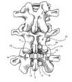
- FIG. 1is a posterior view of a segmentally modular spinal plating system fixed to a portion of the spine.
- FIG. 2is a posterior view of the segmentally modular spinal plating system of FIG. 1 , which includes a spacer assembly, a pair of straight plates, a pair of jogged plates, and three fasteners.
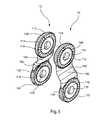
- FIG. 3is a perspective view of the spacer assembly of FIG. 2 .
- FIG. 4is a perspective view of the straight plates of FIG. 2 .
- FIG. 5is a perspective view of the jogged plates of FIG. 2 .
- FIG. 6is a posterior view of a partial assembly of one straight plate of FIG. 4 joined by a fastener to one jogged plate of FIG. 5 .
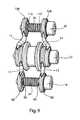
- FIG. 7is a posterior view of the partial assembly of FIG. 6 , joined to the spacer assembly of FIG. 3 .
- FIG. 8is a posterior view of the partial assembly of FIG. 7 , joined to an additional straight plate and an additional jogged plate.
- FIG. 9is a posterior perspective view of the segmentally modular spinal plating system of FIG. 1 .
- FIG. 10is a posterior perspective view of a two-level segmentally modular spinal plating system fixed to a portion of the spine.
- the present inventionrelates to systems and methods for stabilizing the relative motion of spinal vertebrae.
- Those of skill in the artwill recognize that the following description is merely illustrative of the principles of the invention, which may be applied in various ways to provide many different alternative embodiments.
- a posterior viewillustrates a segmentally modular spinal plating system 10 affixed to a portion of the lumbar spine.
- the system 10comprises a non-threaded straight plate 12 , a singly-threaded straight plate 13 , a non-threaded jogged plate 14 , a doubly-threaded jogged plate 15 , and a spacer assembly 16 .
- the straight plates 12 , 13lie on both lateral sides of the spinous process 2 of the lower vertebra, and are connected by a fastener 18 which passes through the non-threaded straight plate 12 , through the spinous process 2 , and through the singly-threaded straight plate 13 .
- the jogged plates 14 , 15lie on both lateral sides of the spinous process 4 of the adjacent vertebra above and are connected by a fastener 20 which passes through the non-threaded jogged plate 14 , through the spinous process 4 and through the doubly-threaded jogged plate 15 .
- the spacer assembly 16is connected to both of the straight plates 12 , 13 and both of the jogged plates 14 , 15 by a fastener 22 .
- the fastener 22lies transverse to the spinal column on an axis about which the plates can pivot; this axis extends along the medial/lateral direction (i.e., left-to-right when viewing FIG. 1 ).
- FIG. 2an enlarged posterior view illustrates the segmentally modular spinal plating system 10 in more detail.
- the two straight plates 12 , 13are secured by a fastener 18 .
- the two jogged plates 14 , 15are secured by a fastener 20 .
- “Jogged plates”refers to plates which are not planar between two ends, but are non-planar or bent between two ends.
- the straight plates 12 , 13 and the jogged plates 14 , 15are linked together by the spacer assembly 16 .
- the spacer assembly 16includes a spacing member 40 and a rim cap 42 .
- the spacer assembly 16is threaded on the fastener 22 .
- the spacer assembly 16is a one-piece unitary construct.
- the fasteners 18 , 20 , 22are threaded bolts.
- the fasteners 18 , 20 , 22need not be threaded bolts but could be non-threaded bolts, bolts with nuts, screws, pins, or rivets, among others.
- FIG. 3illustrates the spacer assembly 16 in an enlarged perspective view.
- the spacing member 40is generally tubular in form; however, the shape of the spacing member 40 is such that it best conforms to the morphology of the area on the spinous processes 2 , 4 which it contacts and can be other non-circular, more organic, bone conforming shapes.
- the spacing member 40has an outer end 44 and an inner end 46 .
- the outer end 44is wider in diameter than the rest of the spacing member 40 , and forms a flange-like shape along a rim 48 .
- a radial spline 50occupies an outer interface surface 49 of the rim 48 .
- a bore 52extends through the longitudinal center of the spacing member 40 .
- the outer cylindrical wall of the spacing memberis a bearing surface 54 .
- the rim cap 42is generally flat and circular, and has an inner side 56 and an outer interface side 58 . Depressed into the inner side 56 is a concavity 64 . A diameter of the concavity 64 is sized to hold the inner end 46 of the spacing member 40 . A radial spline 60 (not visible in FIG. 3 ) occupies an outer interface surface 59 of the outer side 58 . A bore 62 runs through the center of the rim cap 42 .
- the spacing member 40When implanted as part of the segmentally modular spinal plating device 10 , the spacing member 40 (particularly the bearing surface 54 ) and the rim cap 42 come in contact with the sides and outer edge of the spinous processes 2 , 4 as seen in FIG. 1 .
- the spacing member 40 and rim cap 42may be composed of a variety of materials. If dynamic stabilization is desired, the spacing member 40 and rim cap 42 can be composed of a semi-rigid, elastically compliant biocompatible polymer such as polyurethane or the spacing member 40 may be designed with spring elements (not shown) that allow flexibility and compressibility of the spacer assembly 16 when it is loaded by the spinous processes 2 and 4 .
- the spacing member 40 and rim cap 42can be composed of a substantially rigid biocompatible materials including metals such as titanium, cobalt chromium alloys, stainless steel alloys or the like or other substantially rigid materials such as PEEK, Ultra High Molecular weight polyethylene (UHMWPE), Delrin, ceramics, or other biocompatible structural engineering polymers or ceramics. If fusion is desired, the spacing member 40 and rim cap 42 may be composed of natural or synthetic bone material. Finally, if completely dynamic movement is desired, the device 10 may be implanted without a spacer 40 and rim cap 42 , and with a non-threaded rod replacing the fastener 22 .
- an enlarged viewshows the non-threaded straight plate 12 and the singly-threaded straight plate 13 .
- the two straight plates 12 , 13are substantially identical to each other in shape and are symmetrical from side to side. The only difference between the straight plates 12 , 13 is whether or not the bores in the plates are threaded.
- Each straight plate 12 , 13has a substantially planar, elongated elliptical shape with an outer facing side 72 and an inner facing side 74 .
- the center of each straight plate 12 , 13is a planar member 76 , which is terminated at one longitudinal end by a first annulus 78 .
- a non-threaded bore 80perforates the first annulus 78 .
- An outer facing radial spline 82is an outer interface surface 79 of the first annulus 78
- an inner facing radial spline 84is on an inner interface surface 81 of the first annulus 78 .
- the opposite longitudinal end of the planar member 76is terminated by a second annulus 88 .
- a non-threaded bore 90perforates the second annulus 88 .
- a threaded bore 96perforates the second annulus 88 .
- An outer facing radial spline 92is on an outer interface surface 89 of the second annulus 88
- an inner facing radial spline 94is an inner interface surface 91 of the second annulus 88 .
- the non-threaded straight plate 12has two non-threaded bores 80 , 90 , and is otherwise symmetrical, it may be turned side to side or end to end prior to assembly in the device 10 .
- the singly-threaded straight plate 13has one non-threaded bore 80 and one threaded bore 96 . Thus, it may be turned side to side but not end to end to be properly assembled in the device 10 .
- FIG. 5displays the two jogged plates 14 , 15 .
- the jogged plates 14 , 15are identical to each other except for the threading of the bores.
- Each jogged plate 14 , 15has an outer facing side 102 and an inner facing side 104 .
- a central jogged member 106terminates at one longitudinal end at a first annulus 108 .
- a non-threaded bore 110perforates the first annulus 108 .
- a threaded bore 116perforates the first annulus 108 .
- an outer facing radial spline 112is on an outer interface surface 109 of the first annulus 108
- an inner facing radial spline 114is on an inner interface surface 111 of the first annulus 108 .
- the opposite longitudinal end of the jogged member 106is terminated at a second annulus 118 .
- a non-threaded bore 120perforates the second annulus 118 .
- a threaded bore 126perforates the second annulus 118 .
- an outer facing radial spline 122is on an outer interface surface 119 of the second annulus 118
- an inner facing radial spline 124is on an inner interface surface 121 of the second annulus 118 . Because of the non-planar configuration of the jogged plates, the jogged plates 14 , 15 cannot be turned side to side or end to end but must be specifically oriented to be properly assembled in the system 10 .
- FIGS. 6 through 9show the steps in assembly of the device 10 .
- FIG. 6depicts the fastener 22 with the non-threaded straight plate 12 and the non-threaded jogged plate 14 .
- a threaded shaft 32 of the fastener 22is placed through the bore 120 of the second annulus 118 , from the outer facing side 102 to the inner facing side 104 .
- the non-threaded jogged plate 14is slid along the shaft 32 until the second annulus 118 contacts a fastener head 34 .
- the non-threaded straight plate 12is put onto the fastener 22 .
- the bore 80 on the first annulus 78is slid along the threaded shaft 32 , until the first annulus 78 contacts the non-threaded jogged plate 14 .
- the inner radial spline 124 of the non-threaded jogged plate 14engages with the outer radial spline 82 of the non-threaded straight plate 12 , causing the plates 12 , 14 to releasably lock into place relative to one another.
- the interaction of the radial splines 124 , 82allows for very precise adjustment to obtain the desired length of the device 10 .
- the angle at which the plates 12 , 14 engagemay be adjusted by pulling the plates apart, rotating one plate or another around the shaft 32 until the desired position of the plates about the axis is found, then pushing the plates 12 , 14 back together so that the radial splines 82 , 124 engage. Because the bores 80 , 120 of the plates 12 , 14 are not threaded, they can freely rotate around the shaft 32 until locked into place by meshing the splines. Adjusting the angle of the plates 12 , 14 about the axis adjusts the length of the device 10 .
- the axisis defined by interaction between the bores of the plates and the outer surface of the fastener shaft 32 .
- FIG. 7illustrates the addition of the spacer assembly 16 to the partial assembly depicted in FIG. 6 .
- the bore 52 of the spacer member 40is slid onto the threaded shaft 32 of the fastener 22 .
- the spacer member 40is slid onto the fastener 22 until the outer radial spline 50 of the spacer member 40 engages with the inner radial spline 84 of the non-threaded straight plate 12 .
- the rim cap 42is then slid onto the fastener 22 .
- the bore 62 of the rim cap 42is slid onto the threaded shaft 32 of the fastener 22 , until the concavity 64 fits over the inner end 46 of the spacer member 40 .
- the spacer member 40 and the rim cap 42may first be press fit or threaded together, with the inner end 46 fitting into the concavity 64 , and then slid as a single piece onto the fastener 22 .
- the singly-threaded straight plate 13 and the doubly-threaded jogged plate 15are shown as added to the partial assembly depicted in FIG. 7 .
- the non-threaded bore 80 of the first annulus 78 on the singly-threaded straight plate 13is slid onto the threaded shaft 32 (not visible) of the fastener 22 .
- the inner radial spline 84 of the singly-threaded straight plate 13engages with the outer radial spline 60 on the rim cap 42 .
- the singly-threaded straight plate 13may be rotated around the threaded shaft 32 until the desired position about the axis is achieved, before the meshing of the splines 60 , 84 releasably locks the singly-threaded plate 13 into place.
- the doubly-threaded jogged plate 15is the last plate to be added to the assembly.
- the threaded bore 126 on its second annulus 118is screwed onto the threaded shaft 32 , until the inner radial spline 124 engages with the outer radial spline 82 on the singly-threaded straight plate 13 .
- plates 13 and 15may be adjusted about axis until the desired angle and length for the device 10 is found.
- FIG. 9depicts the system 10 as fully assembled, with the fasteners 18 and 20 in place.
- the partially assembled system 10is placed on the spine so that the spacing member 40 is between the spinous processes 2 , 4 of the vertebrae.
- the two first annuli 108 of the jogged plates 14 , 15extend in a cephalad direction on either side of the upper spinous process 4 .
- the two second annuli 88 of the straight plates 12 , 13extend in a caudal direction on either side of the lower spinous process 2 .
- the threaded shaft 24 of the fastener 18passes through the non-threaded bore 90 of the non-threaded straight plate 12 , through the spinous process 2 of the lower vertebra, then screws into the threaded bore 96 of the singly-threaded straight plate 13 .
- the engagement of the threads on the threaded shaft 24 with the threads in the threaded bore 96tightens the fastener 18 in place.
- the threaded shaft 26 of the fastener 20passes through the non-threaded bore 110 of the non-threaded jogged plate 14 , through the spinous process 4 of the upper vertebra, then screws into the threaded bore 116 of the doubly-threaded jogged plate 15 .
- fasteners 18 and 20pass through the spinous processes 2 and 4 to fasten the plates to the spinous processes.
- other means of attachmentmay be used to fasten the plates to the spinous processes, such as bands, clamps, cables, wire, and sutures, among others.
- FIG. 10illustrates a two-level segmentally modular spinal plating system 210 fixed in place in a portion of the spine.
- the system 210comprises a single level system 10 , plus two additional non-threaded straight plates 12 , an additional singly-threaded straight plate 13 , a doubly-threaded straight plate 17 , an additional spacer assembly 16 , and two additional fasteners.
- a non-threaded straight plate 12 and the doubly-threaded straight plate 17are added to the upper level of the single level system 10 , and connect the single level system 10 to an additional fastener 22 .
- the fastener 22retains the non-threaded straight plate 12 , a second non-threaded straight plate 12 , a spacer assembly 16 , a singly-threaded straight plate 13 , and the doubly-threaded straight plate 17 .
- the spacer assembly 16fits between the spinous processes 4 and 6 .
- a final fastener 18retains one non-threaded straight plate 12 and the singly-threaded straight plate 13 .
- the two spacer assemblies 16may be composed of like material to provide similar stabilization between all involved vertebrae, or the two spacer assemblies 16 may be of different materials to provide different types of stabilization between the different vertebrae.
- the two level system 210enables stabilization between three vertebrae; additional levels may be added if desired, again with interchangeable spacer assemblies 16 .
- FIGS. 1 through 10utilize a threaded bolt for each of the fasteners 18 , 20 , 22 , and plates 12 , 13 , 14 , 15 with bores that are threaded or not threaded.
- An alternative embodimentcould have bolt fasteners that are shallowly threaded along most of the shaft, and deeply threaded at the end of the shaft.
- all the bores of the platecould be threaded, but only the plates that connect at the end of the shaft (the outermost plates) would threadably engage the shaft (where the shaft is deeply threaded) and tighten onto the fastener.
- the platesneed not be threaded at all but a threaded nut could be added on the end of the threaded fastener shaft to tighten all the components together.
- Another alternative embodimentdoes not have radial splines on the outer or inner interface surfaces of the plates or other means of regulating movement between the plates. This allows for dynamic movement between the plates since the interface between the plates is not restricted by any mechanism that prevent rotation or sliding between the plates. Plates according to this alternative embodiment, when used in conjunction with a more elastically compliant spacer, allow for more dynamic movement between vertebrae.
- Another embodimentpermits dynamic movement between the plates, as in the embodiment of the preceding paragraph, and also provides resilient force, for example, via the addition of springs, to stabilize such dynamic movement.
- torsional springsmay be registered on the plates 12 , 14 , on the plates 13 , 15 , or at the junctions between both pairs of plates 12 , 14 , 13 , 15 .
- damping forcemay be applied to the motion between the plates 12 , 14 , 13 , 15 , for example, through the use of a frictional yet movable interface (not shown) such as frictional coatings on the various interface surfaces of the plates 12 , 14 , 13 , 15 , or a sealed chamber containing a viscous fluid and a damper that moves through the fluid in response to relative rotation between the plates 12 , 14 , 13 , 15 (not shown).
- frictional yet movable interfacesuch as frictional coatings on the various interface surfaces of the plates 12 , 14 , 13 , 15 , or a sealed chamber containing a viscous fluid and a damper that moves through the fluid in response to relative rotation between the plates 12 , 14 , 13 , 15 (not shown).
Landscapes
- Health & Medical Sciences (AREA)
- Orthopedic Medicine & Surgery (AREA)
- Life Sciences & Earth Sciences (AREA)
- Neurology (AREA)
- Surgery (AREA)
- Heart & Thoracic Surgery (AREA)
- Engineering & Computer Science (AREA)
- Biomedical Technology (AREA)
- Nuclear Medicine, Radiotherapy & Molecular Imaging (AREA)
- Medical Informatics (AREA)
- Molecular Biology (AREA)
- Animal Behavior & Ethology (AREA)
- General Health & Medical Sciences (AREA)
- Public Health (AREA)
- Veterinary Medicine (AREA)
- Prostheses (AREA)
Abstract
Description
Claims (22)
Priority Applications (2)
| Application Number | Priority Date | Filing Date | Title |
|---|---|---|---|
| US11/809,602US8048120B1 (en) | 2006-05-31 | 2007-05-31 | System and method for segmentally modular spinal plating |
| US13/235,748US20120010660A1 (en) | 2006-05-31 | 2011-09-19 | System and method for segmentally modular spinal plating |
Applications Claiming Priority (2)
| Application Number | Priority Date | Filing Date | Title |
|---|---|---|---|
| US80359406P | 2006-05-31 | 2006-05-31 | |
| US11/809,602US8048120B1 (en) | 2006-05-31 | 2007-05-31 | System and method for segmentally modular spinal plating |
Related Child Applications (1)
| Application Number | Title | Priority Date | Filing Date |
|---|---|---|---|
| US13/235,748ContinuationUS20120010660A1 (en) | 2006-05-31 | 2011-09-19 | System and method for segmentally modular spinal plating |
Publications (1)
| Publication Number | Publication Date |
|---|---|
| US8048120B1true US8048120B1 (en) | 2011-11-01 |
Family
ID=44839556
Family Applications (2)
| Application Number | Title | Priority Date | Filing Date |
|---|---|---|---|
| US11/809,602Expired - Fee RelatedUS8048120B1 (en) | 2006-05-31 | 2007-05-31 | System and method for segmentally modular spinal plating |
| US13/235,748AbandonedUS20120010660A1 (en) | 2006-05-31 | 2011-09-19 | System and method for segmentally modular spinal plating |
Family Applications After (1)
| Application Number | Title | Priority Date | Filing Date |
|---|---|---|---|
| US13/235,748AbandonedUS20120010660A1 (en) | 2006-05-31 | 2011-09-19 | System and method for segmentally modular spinal plating |
Country Status (1)
| Country | Link |
|---|---|
| US (2) | US8048120B1 (en) |
Cited By (41)
| Publication number | Priority date | Publication date | Assignee | Title |
|---|---|---|---|---|
| US20090198277A1 (en)* | 2007-12-28 | 2009-08-06 | Osteomed Spine, Inc. | Bone tissue fixation device and method |
| US20110066186A1 (en)* | 2009-09-11 | 2011-03-17 | Boyer Ii Michael Lee | Spinous Process Fusion Devices |
| US20110087285A1 (en)* | 2009-10-14 | 2011-04-14 | Kaveh Khajavi | Spinous process fixation plate and minimally invasive method for placement |
| US20120078303A1 (en)* | 2010-09-27 | 2012-03-29 | Mmsn Limited Partnership | Medical apparatus and method for spinal surgery |
| US20120109204A1 (en)* | 2008-10-23 | 2012-05-03 | Linares Medical Devices, Llc | Assembleable jack braces for seating and supporting angular processes |
| US20120109202A1 (en)* | 2010-04-30 | 2012-05-03 | Neuraxis Llc | Intersegmental motion preservation system for use in the spine and methods for use thereof |
| US20120215262A1 (en)* | 2011-02-16 | 2012-08-23 | Interventional Spine, Inc. | Spinous process spacer and implantation procedure |
| US20120323276A1 (en)* | 2011-06-17 | 2012-12-20 | Bryan Okamoto | Expandable interspinous device |
| US8425560B2 (en)* | 2011-03-09 | 2013-04-23 | Farzad Massoudi | Spinal implant device with fixation plates and lag screws and method of implanting |
| US20130178904A1 (en)* | 2009-12-28 | 2013-07-11 | Gregory B. Arcenio | Systems and methods for performing spinal fusion |
| US8496689B2 (en) | 2011-02-23 | 2013-07-30 | Farzad Massoudi | Spinal implant device with fusion cage and fixation plates and method of implanting |
| WO2013167731A1 (en)* | 2012-05-11 | 2013-11-14 | Aesculap Ag | Implant for stabilizing spinous processes |
| US20140128917A1 (en)* | 2007-01-29 | 2014-05-08 | Samy Abdou | Inter-vertebral orthopedic device placement |
| US8882805B1 (en) | 2011-08-02 | 2014-11-11 | Lawrence Maccree | Spinal fixation system |
| US8911476B2 (en) | 2009-06-23 | 2014-12-16 | Osteomed, Llc | Bone plates, screws, and instruments |
| US20150025583A1 (en)* | 2012-10-22 | 2015-01-22 | Spectrum Spine Ip Holdings, Llc | Inter-spinous process device and method |
| US8961564B2 (en) | 2008-12-23 | 2015-02-24 | Osteomed Llc | Bone tissue clamp |
| US20150066087A1 (en)* | 2009-09-11 | 2015-03-05 | Globus Medical, Inc | Spinous Process Fusion Devices |
| US20150320570A1 (en)* | 2010-06-01 | 2015-11-12 | Globus Medical, Inc. | Spinal implants and methods of use thereof |
| US9211147B2 (en) | 2009-06-23 | 2015-12-15 | Osteomed Llc | Spinous process fusion implants |
| US20160113687A1 (en)* | 2007-01-11 | 2016-04-28 | Lanx, Inc. | Spinous process implants and associated methods |
| USD757943S1 (en) | 2011-07-14 | 2016-05-31 | Nuvasive, Inc. | Spinous process plate |
| US9743960B2 (en) | 2007-01-11 | 2017-08-29 | Zimmer Biomet Spine, Inc. | Interspinous implants and methods |
| US9770271B2 (en) | 2005-10-25 | 2017-09-26 | Zimmer Biomet Spine, Inc. | Spinal implants and methods |
| US20170311993A1 (en)* | 2010-12-13 | 2017-11-02 | Globus Medical, Inc. | Spinous process fusion devices and methods thereof |
| US9861400B2 (en) | 2007-01-11 | 2018-01-09 | Zimmer Biomet Spine, Inc. | Spinous process implants and associated methods |
| US10448977B1 (en) | 2012-03-31 | 2019-10-22 | Ali H. MESIWALA | Interspinous device and related methods |
| US10543107B2 (en) | 2009-12-07 | 2020-01-28 | Samy Abdou | Devices and methods for minimally invasive spinal stabilization and instrumentation |
| US10548740B1 (en) | 2016-10-25 | 2020-02-04 | Samy Abdou | Devices and methods for vertebral bone realignment |
| US10575961B1 (en) | 2011-09-23 | 2020-03-03 | Samy Abdou | Spinal fixation devices and methods of use |
| US10695105B2 (en) | 2012-08-28 | 2020-06-30 | Samy Abdou | Spinal fixation devices and methods of use |
| US10857003B1 (en) | 2015-10-14 | 2020-12-08 | Samy Abdou | Devices and methods for vertebral stabilization |
| US10918498B2 (en) | 2004-11-24 | 2021-02-16 | Samy Abdou | Devices and methods for inter-vertebral orthopedic device placement |
| US10945857B2 (en) | 2014-06-04 | 2021-03-16 | Wenzel Spine, Inc. | Bilaterally expanding intervertebral body fusion device |
| US10959786B2 (en) | 2015-06-05 | 2021-03-30 | Wenzel Spine, Inc. | Methods for data processing for intra-operative navigation systems |
| US10973648B1 (en) | 2016-10-25 | 2021-04-13 | Samy Abdou | Devices and methods for vertebral bone realignment |
| US11006982B2 (en) | 2012-02-22 | 2021-05-18 | Samy Abdou | Spinous process fixation devices and methods of use |
| US11173040B2 (en) | 2012-10-22 | 2021-11-16 | Cogent Spine, LLC | Devices and methods for spinal stabilization and instrumentation |
| US11179248B2 (en) | 2018-10-02 | 2021-11-23 | Samy Abdou | Devices and methods for spinal implantation |
| US11707203B2 (en) | 2016-10-11 | 2023-07-25 | Wenzel Spine, Inc. | Systems for generating image-based measurements during diagnosis |
| US11812923B2 (en) | 2011-10-07 | 2023-11-14 | Alan Villavicencio | Spinal fixation device |
Families Citing this family (2)
| Publication number | Priority date | Publication date | Assignee | Title |
|---|---|---|---|---|
| US8623024B2 (en) | 2010-03-12 | 2014-01-07 | Southern Spine, Llc | Implantation tools for interspinous process spacing device |
| US9668786B2 (en)* | 2012-11-16 | 2017-06-06 | Southern Spine, Llc | Linkage systems for interspinous process spacing device |
Citations (24)
| Publication number | Priority date | Publication date | Assignee | Title |
|---|---|---|---|---|
| US3648691A (en) | 1970-02-24 | 1972-03-14 | Univ Colorado State Res Found | Method of applying vertebral appliance |
| US5496318A (en)* | 1993-01-08 | 1996-03-05 | Advanced Spine Fixation Systems, Inc. | Interspinous segmental spine fixation device |
| US5645599A (en)* | 1994-07-26 | 1997-07-08 | Fixano | Interspinal vertebral implant |
| US6126689A (en)* | 1998-06-15 | 2000-10-03 | Expanding Concepts, L.L.C. | Collapsible and expandable interbody fusion device |
| US6331179B1 (en)* | 2000-01-06 | 2001-12-18 | Spinal Concepts, Inc. | System and method for stabilizing the human spine with a bone plate |
| WO2003007829A1 (en) | 2001-07-20 | 2003-01-30 | Spinal Concepts, Inc. | Spinal stabilization system and method |
| US6626944B1 (en)* | 1998-02-20 | 2003-09-30 | Jean Taylor | Interspinous prosthesis |
| US6652527B2 (en)* | 1998-10-20 | 2003-11-25 | St. Francis Medical Technologies, Inc. | Supplemental spine fixation device and method |
| US6695842B2 (en)* | 1997-10-27 | 2004-02-24 | St. Francis Medical Technologies, Inc. | Interspinous process distraction system and method with positionable wing and method |
| US20040167625A1 (en)* | 1999-01-27 | 2004-08-26 | Disc-O-Tech Orthopedic Technologies Inc. | Spacer filler |
| US20040249379A1 (en) | 2003-02-12 | 2004-12-09 | Winslow Charles J. | System and method for immobilizing adjacent spinous processes |
| US20050102028A1 (en)* | 2003-11-07 | 2005-05-12 | Uri Arnin | Spinal prostheses |
| US6932820B2 (en) | 2002-01-08 | 2005-08-23 | Said G. Osman | Uni-directional dynamic spinal fixation device |
| US20050203512A1 (en)* | 2004-03-09 | 2005-09-15 | Depuy Spine, Inc. | Posterior process dynamic spacer |
| US6946000B2 (en)* | 2000-12-22 | 2005-09-20 | Spine Next | Intervertebral implant with deformable wedge |
| US20060015181A1 (en) | 2004-07-19 | 2006-01-19 | Biomet Merck France (50% Interest) | Interspinous vertebral implant |
| US20060058790A1 (en) | 2004-08-03 | 2006-03-16 | Carl Allen L | Spinous process reinforcement device and method |
| US20060085070A1 (en)* | 2004-10-20 | 2006-04-20 | Vertiflex, Inc. | Systems and methods for posterior dynamic stabilization of the spine |
| US7101375B2 (en)* | 1997-01-02 | 2006-09-05 | St. Francis Medical Technologies, Inc. | Spine distraction implant |
| US20060247640A1 (en)* | 2005-04-29 | 2006-11-02 | Sdgi Holdings, Inc. | Spinous process stabilization devices and methods |
| US20070149972A1 (en)* | 2003-05-16 | 2007-06-28 | Yoshinobu Iwasaki | Interspinous spacer |
| US20070270840A1 (en)* | 2006-03-21 | 2007-11-22 | Spinefrontier Lls | Spinous process fixation device |
| US20080033552A1 (en)* | 2004-05-17 | 2008-02-07 | Canon Kasushiki Kaisha | Sensor Device |
| US7442208B2 (en)* | 2001-08-20 | 2008-10-28 | Synthes (U.S.A.) | Interspinal prosthesis |
Family Cites Families (2)
| Publication number | Priority date | Publication date | Assignee | Title |
|---|---|---|---|---|
| US5643260A (en)* | 1995-02-14 | 1997-07-01 | Smith & Nephew, Inc. | Orthopedic fixation system |
| US7931674B2 (en)* | 2005-03-21 | 2011-04-26 | Kyphon Sarl | Interspinous process implant having deployable wing and method of implantation |
- 2007
- 2007-05-31USUS11/809,602patent/US8048120B1/ennot_activeExpired - Fee Related
- 2011
- 2011-09-19USUS13/235,748patent/US20120010660A1/ennot_activeAbandoned
Patent Citations (26)
| Publication number | Priority date | Publication date | Assignee | Title |
|---|---|---|---|---|
| US3648691A (en) | 1970-02-24 | 1972-03-14 | Univ Colorado State Res Found | Method of applying vertebral appliance |
| US5496318A (en)* | 1993-01-08 | 1996-03-05 | Advanced Spine Fixation Systems, Inc. | Interspinous segmental spine fixation device |
| US5645599A (en)* | 1994-07-26 | 1997-07-08 | Fixano | Interspinal vertebral implant |
| US7101375B2 (en)* | 1997-01-02 | 2006-09-05 | St. Francis Medical Technologies, Inc. | Spine distraction implant |
| US6695842B2 (en)* | 1997-10-27 | 2004-02-24 | St. Francis Medical Technologies, Inc. | Interspinous process distraction system and method with positionable wing and method |
| US6626944B1 (en)* | 1998-02-20 | 2003-09-30 | Jean Taylor | Interspinous prosthesis |
| US6126689A (en)* | 1998-06-15 | 2000-10-03 | Expanding Concepts, L.L.C. | Collapsible and expandable interbody fusion device |
| US6652527B2 (en)* | 1998-10-20 | 2003-11-25 | St. Francis Medical Technologies, Inc. | Supplemental spine fixation device and method |
| US20040167625A1 (en)* | 1999-01-27 | 2004-08-26 | Disc-O-Tech Orthopedic Technologies Inc. | Spacer filler |
| US6331179B1 (en)* | 2000-01-06 | 2001-12-18 | Spinal Concepts, Inc. | System and method for stabilizing the human spine with a bone plate |
| US6946000B2 (en)* | 2000-12-22 | 2005-09-20 | Spine Next | Intervertebral implant with deformable wedge |
| US20030040746A1 (en)* | 2001-07-20 | 2003-02-27 | Mitchell Margaret E. | Spinal stabilization system and method |
| WO2003007829A1 (en) | 2001-07-20 | 2003-01-30 | Spinal Concepts, Inc. | Spinal stabilization system and method |
| US7442208B2 (en)* | 2001-08-20 | 2008-10-28 | Synthes (U.S.A.) | Interspinal prosthesis |
| US6932820B2 (en) | 2002-01-08 | 2005-08-23 | Said G. Osman | Uni-directional dynamic spinal fixation device |
| US20040249379A1 (en) | 2003-02-12 | 2004-12-09 | Winslow Charles J. | System and method for immobilizing adjacent spinous processes |
| US7335203B2 (en)* | 2003-02-12 | 2008-02-26 | Kyphon Inc. | System and method for immobilizing adjacent spinous processes |
| US20070149972A1 (en)* | 2003-05-16 | 2007-06-28 | Yoshinobu Iwasaki | Interspinous spacer |
| US20050102028A1 (en)* | 2003-11-07 | 2005-05-12 | Uri Arnin | Spinal prostheses |
| US20050203512A1 (en)* | 2004-03-09 | 2005-09-15 | Depuy Spine, Inc. | Posterior process dynamic spacer |
| US20080033552A1 (en)* | 2004-05-17 | 2008-02-07 | Canon Kasushiki Kaisha | Sensor Device |
| US20060015181A1 (en) | 2004-07-19 | 2006-01-19 | Biomet Merck France (50% Interest) | Interspinous vertebral implant |
| US20060058790A1 (en) | 2004-08-03 | 2006-03-16 | Carl Allen L | Spinous process reinforcement device and method |
| US20060085070A1 (en)* | 2004-10-20 | 2006-04-20 | Vertiflex, Inc. | Systems and methods for posterior dynamic stabilization of the spine |
| US20060247640A1 (en)* | 2005-04-29 | 2006-11-02 | Sdgi Holdings, Inc. | Spinous process stabilization devices and methods |
| US20070270840A1 (en)* | 2006-03-21 | 2007-11-22 | Spinefrontier Lls | Spinous process fixation device |
Cited By (81)
| Publication number | Priority date | Publication date | Assignee | Title |
|---|---|---|---|---|
| US11992423B2 (en) | 2004-11-24 | 2024-05-28 | Samy Abdou | Devices and methods for inter-vertebral orthopedic device placement |
| US11096799B2 (en) | 2004-11-24 | 2021-08-24 | Samy Abdou | Devices and methods for inter-vertebral orthopedic device placement |
| US10918498B2 (en) | 2004-11-24 | 2021-02-16 | Samy Abdou | Devices and methods for inter-vertebral orthopedic device placement |
| US9770271B2 (en) | 2005-10-25 | 2017-09-26 | Zimmer Biomet Spine, Inc. | Spinal implants and methods |
| US20160113687A1 (en)* | 2007-01-11 | 2016-04-28 | Lanx, Inc. | Spinous process implants and associated methods |
| US9861400B2 (en) | 2007-01-11 | 2018-01-09 | Zimmer Biomet Spine, Inc. | Spinous process implants and associated methods |
| US9743960B2 (en) | 2007-01-11 | 2017-08-29 | Zimmer Biomet Spine, Inc. | Interspinous implants and methods |
| US9724136B2 (en)* | 2007-01-11 | 2017-08-08 | Zimmer Biomet Spine, Inc. | Spinous process implants and associated methods |
| US20140128917A1 (en)* | 2007-01-29 | 2014-05-08 | Samy Abdou | Inter-vertebral orthopedic device placement |
| US8940019B2 (en)* | 2007-12-28 | 2015-01-27 | Osteomed Spine, Inc. | Bone tissue fixation device and method |
| US20090198277A1 (en)* | 2007-12-28 | 2009-08-06 | Osteomed Spine, Inc. | Bone tissue fixation device and method |
| US20120109204A1 (en)* | 2008-10-23 | 2012-05-03 | Linares Medical Devices, Llc | Assembleable jack braces for seating and supporting angular processes |
| US8574267B2 (en)* | 2008-10-23 | 2013-11-05 | Linares Medical Devices, Llc | Assembleable jack braces for seating and supporting angular processes |
| US8961564B2 (en) | 2008-12-23 | 2015-02-24 | Osteomed Llc | Bone tissue clamp |
| US9211147B2 (en) | 2009-06-23 | 2015-12-15 | Osteomed Llc | Spinous process fusion implants |
| US9456858B2 (en) | 2009-06-23 | 2016-10-04 | Osteomed, Llc | Bone plates, screws and instruments |
| US10010356B2 (en) | 2009-06-23 | 2018-07-03 | Wenzel Spine, Inc. | Bone plates, screws and instruments |
| US8911476B2 (en) | 2009-06-23 | 2014-12-16 | Osteomed, Llc | Bone plates, screws, and instruments |
| US20150066087A1 (en)* | 2009-09-11 | 2015-03-05 | Globus Medical, Inc | Spinous Process Fusion Devices |
| US20110066186A1 (en)* | 2009-09-11 | 2011-03-17 | Boyer Ii Michael Lee | Spinous Process Fusion Devices |
| US10085777B2 (en)* | 2009-09-11 | 2018-10-02 | Globus Medical Inc. | Spinous process fusion devices |
| US20170143383A1 (en)* | 2009-09-11 | 2017-05-25 | Globus Medical, Inc. | Spinous process fusion devices |
| US9179944B2 (en)* | 2009-09-11 | 2015-11-10 | Globus Medical, Inc. | Spinous process fusion devices |
| US9592082B2 (en)* | 2009-09-11 | 2017-03-14 | Globus Medical, Inc. | Spinous process fusion devices |
| US20110087285A1 (en)* | 2009-10-14 | 2011-04-14 | Kaveh Khajavi | Spinous process fixation plate and minimally invasive method for placement |
| US9149305B2 (en)* | 2009-10-14 | 2015-10-06 | Latitude Holdings, Llc | Spinous process fixation plate and minimally invasive method for placement |
| US11918486B2 (en) | 2009-12-07 | 2024-03-05 | Samy Abdou | Devices and methods for minimally invasive spinal stabilization and instrumentation |
| US10610380B2 (en) | 2009-12-07 | 2020-04-07 | Samy Abdou | Devices and methods for minimally invasive spinal stabilization and instrumentation |
| US10543107B2 (en) | 2009-12-07 | 2020-01-28 | Samy Abdou | Devices and methods for minimally invasive spinal stabilization and instrumentation |
| US10857004B2 (en) | 2009-12-07 | 2020-12-08 | Samy Abdou | Devices and methods for minimally invasive spinal stabilization and instrumentation |
| US10945861B2 (en) | 2009-12-07 | 2021-03-16 | Samy Abdou | Devices and methods for minimally invasive spinal stabilization and instrumentation |
| US20130178904A1 (en)* | 2009-12-28 | 2013-07-11 | Gregory B. Arcenio | Systems and methods for performing spinal fusion |
| US20120109202A1 (en)* | 2010-04-30 | 2012-05-03 | Neuraxis Llc | Intersegmental motion preservation system for use in the spine and methods for use thereof |
| US20150320570A1 (en)* | 2010-06-01 | 2015-11-12 | Globus Medical, Inc. | Spinal implants and methods of use thereof |
| US9301787B2 (en)* | 2010-09-27 | 2016-04-05 | Mmsn Limited Partnership | Medical apparatus and method for spinal surgery |
| US20120078303A1 (en)* | 2010-09-27 | 2012-03-29 | Mmsn Limited Partnership | Medical apparatus and method for spinal surgery |
| US10213235B2 (en)* | 2010-12-13 | 2019-02-26 | Globus Medical, Inc. | Spinous process fusion devices and methods thereof |
| US20190142479A1 (en)* | 2010-12-13 | 2019-05-16 | Globus Medical, Inc. | Spinous process fusion devices and methods thereof |
| US10722277B2 (en)* | 2010-12-13 | 2020-07-28 | Globus Medical Inc. | Spinous process fusion devices and methods thereof |
| US20170311993A1 (en)* | 2010-12-13 | 2017-11-02 | Globus Medical, Inc. | Spinous process fusion devices and methods thereof |
| US20120215262A1 (en)* | 2011-02-16 | 2012-08-23 | Interventional Spine, Inc. | Spinous process spacer and implantation procedure |
| US10052138B2 (en) | 2011-02-23 | 2018-08-21 | Farzad Massoudi | Method for implanting spinal implant device with fusion cage |
| US8496689B2 (en) | 2011-02-23 | 2013-07-30 | Farzad Massoudi | Spinal implant device with fusion cage and fixation plates and method of implanting |
| US10080588B2 (en) | 2011-02-23 | 2018-09-25 | Farzad Massoudi | Spinal implant device with fixation plates and method of implanting |
| US9084639B2 (en) | 2011-02-23 | 2015-07-21 | Farzad Massoudi | Spinal implant device with fusion cage and fixation plates and method of implanting |
| US8425560B2 (en)* | 2011-03-09 | 2013-04-23 | Farzad Massoudi | Spinal implant device with fixation plates and lag screws and method of implanting |
| US10143501B2 (en) | 2011-06-17 | 2018-12-04 | Aurora Spine, Inc. | Expandable interspinous device |
| US9387016B2 (en)* | 2011-06-17 | 2016-07-12 | Phygen, Llc | Expandable interspinous device |
| US20130158604A1 (en)* | 2011-06-17 | 2013-06-20 | Bryan Okamoto | Expandable Interspinous Device |
| US20120323276A1 (en)* | 2011-06-17 | 2012-12-20 | Bryan Okamoto | Expandable interspinous device |
| USD757943S1 (en) | 2011-07-14 | 2016-05-31 | Nuvasive, Inc. | Spinous process plate |
| US8882805B1 (en) | 2011-08-02 | 2014-11-11 | Lawrence Maccree | Spinal fixation system |
| US11517449B2 (en) | 2011-09-23 | 2022-12-06 | Samy Abdou | Spinal fixation devices and methods of use |
| US10575961B1 (en) | 2011-09-23 | 2020-03-03 | Samy Abdou | Spinal fixation devices and methods of use |
| US11324608B2 (en) | 2011-09-23 | 2022-05-10 | Samy Abdou | Spinal fixation devices and methods of use |
| US12167973B2 (en) | 2011-09-23 | 2024-12-17 | Samy Abdou | Spinal fixation devices and methods of use |
| US11812923B2 (en) | 2011-10-07 | 2023-11-14 | Alan Villavicencio | Spinal fixation device |
| US11006982B2 (en) | 2012-02-22 | 2021-05-18 | Samy Abdou | Spinous process fixation devices and methods of use |
| US11839413B2 (en) | 2012-02-22 | 2023-12-12 | Samy Abdou | Spinous process fixation devices and methods of use |
| US10448977B1 (en) | 2012-03-31 | 2019-10-22 | Ali H. MESIWALA | Interspinous device and related methods |
| JP2015516235A (en)* | 2012-05-11 | 2015-06-11 | アエスキュラップ アーゲー | Implants for stabilizing spinous processes |
| US9192414B2 (en) | 2012-05-11 | 2015-11-24 | Aesculap Ag | Implant for stabilizing spinous processes |
| WO2013167731A1 (en)* | 2012-05-11 | 2013-11-14 | Aesculap Ag | Implant for stabilizing spinous processes |
| US10695105B2 (en) | 2012-08-28 | 2020-06-30 | Samy Abdou | Spinal fixation devices and methods of use |
| US11559336B2 (en) | 2012-08-28 | 2023-01-24 | Samy Abdou | Spinal fixation devices and methods of use |
| US11918483B2 (en) | 2012-10-22 | 2024-03-05 | Cogent Spine Llc | Devices and methods for spinal stabilization and instrumentation |
| US11173040B2 (en) | 2012-10-22 | 2021-11-16 | Cogent Spine, LLC | Devices and methods for spinal stabilization and instrumentation |
| US20150025583A1 (en)* | 2012-10-22 | 2015-01-22 | Spectrum Spine Ip Holdings, Llc | Inter-spinous process device and method |
| US9717540B2 (en)* | 2012-10-22 | 2017-08-01 | Spectrum Spine Ip Holdings, Llc | Inter-spinous process device and method |
| US10945857B2 (en) | 2014-06-04 | 2021-03-16 | Wenzel Spine, Inc. | Bilaterally expanding intervertebral body fusion device |
| US10959786B2 (en) | 2015-06-05 | 2021-03-30 | Wenzel Spine, Inc. | Methods for data processing for intra-operative navigation systems |
| US11246718B2 (en) | 2015-10-14 | 2022-02-15 | Samy Abdou | Devices and methods for vertebral stabilization |
| US10857003B1 (en) | 2015-10-14 | 2020-12-08 | Samy Abdou | Devices and methods for vertebral stabilization |
| US11707203B2 (en) | 2016-10-11 | 2023-07-25 | Wenzel Spine, Inc. | Systems for generating image-based measurements during diagnosis |
| US10548740B1 (en) | 2016-10-25 | 2020-02-04 | Samy Abdou | Devices and methods for vertebral bone realignment |
| US11752008B1 (en) | 2016-10-25 | 2023-09-12 | Samy Abdou | Devices and methods for vertebral bone realignment |
| US11259935B1 (en) | 2016-10-25 | 2022-03-01 | Samy Abdou | Devices and methods for vertebral bone realignment |
| US11058548B1 (en) | 2016-10-25 | 2021-07-13 | Samy Abdou | Devices and methods for vertebral bone realignment |
| US10973648B1 (en) | 2016-10-25 | 2021-04-13 | Samy Abdou | Devices and methods for vertebral bone realignment |
| US10744000B1 (en) | 2016-10-25 | 2020-08-18 | Samy Abdou | Devices and methods for vertebral bone realignment |
| US11179248B2 (en) | 2018-10-02 | 2021-11-23 | Samy Abdou | Devices and methods for spinal implantation |
Also Published As
| Publication number | Publication date |
|---|---|
| US20120010660A1 (en) | 2012-01-12 |
Similar Documents
| Publication | Publication Date | Title |
|---|---|---|
| US8048120B1 (en) | System and method for segmentally modular spinal plating | |
| US7993373B2 (en) | Polyaxial orthopedic fastening apparatus | |
| US10987139B2 (en) | Uniplanar bone screw | |
| US20220401224A1 (en) | Interspinous implants | |
| US8900273B2 (en) | Taper-locking fixation system | |
| US9844399B2 (en) | Facet joint implant crosslinking apparatus and method | |
| US8303631B2 (en) | Systems and methods for posterior dynamic stabilization | |
| US8016861B2 (en) | Versatile polyaxial connector assembly and method for dynamic stabilization of the spine | |
| US8025680B2 (en) | Systems and methods for posterior dynamic stabilization of the spine | |
| US7377922B2 (en) | Transfer ring for offset tapered 3D connector | |
| EP2445426B1 (en) | Posterior dynamic stabilization device having a mobile anchor | |
| AU2012211951B2 (en) | Translaminar interspinous stabilization system | |
| US20070219556A1 (en) | System and methods for posterior dynamic stabilization of the spine | |
| US20070161994A1 (en) | Hinged Polyaxial Screw and methods of use | |
| US20100174315A1 (en) | Device for spinal fusion | |
| US20110264221A1 (en) | Interspinous Fusion Device and Method | |
| WO2011031824A1 (en) | Spinal stabilization system | |
| US20250090203A1 (en) | Orthopedic Fixation Devices and Methods of Installation Thereof | |
| US8303628B2 (en) | Spinal stabilization system | |
| KR20070039068A (en) | Systems and Methods for Spinal Stabilization |
Legal Events
| Date | Code | Title | Description |
|---|---|---|---|
| AS | Assignment | Owner name:MEDICINELODGE, INC., UTAH Free format text:ASSIGNMENT OF ASSIGNORS INTEREST;ASSIGNORS:FALLIN, T. WADE;JUSTIN, DANIEL F.;REEL/FRAME:019478/0862 Effective date:20070525 | |
| AS | Assignment | Owner name:PNC BANK, NATIONAL ASSOCIATION, AS AGENT, NEW JERS Free format text:SECURITY AGREEMENT;ASSIGNORS:IMDS CORPORATION;FRONTIER BIOMEDICAL, LLC;REEL/FRAME:028157/0389 Effective date:20120502 | |
| AS | Assignment | Owner name:FRONTIER BIOMEDICAL, LLC, UTAH Free format text:RELEASE BY SECURED PARTY;ASSIGNOR:PNC BANK;REEL/FRAME:031174/0714 Effective date:20130830 Owner name:IMDS CORPORATION, UTAH Free format text:RELEASE BY SECURED PARTY;ASSIGNOR:PNC BANK;REEL/FRAME:031174/0714 Effective date:20130830 | |
| REMI | Maintenance fee reminder mailed | ||
| LAPS | Lapse for failure to pay maintenance fees | ||
| AS | Assignment | Owner name:IMDS CORPORATION, TEXAS Free format text:RELEASE BY SECURED PARTY;ASSIGNOR:PNC BANK, NATIONAL ASSOCIATION, AS AGENT;REEL/FRAME:037163/0367 Effective date:20151127 | |
| STCH | Information on status: patent discontinuation | Free format text:PATENT EXPIRED DUE TO NONPAYMENT OF MAINTENANCE FEES UNDER 37 CFR 1.362 | |
| FP | Lapsed due to failure to pay maintenance fee | Effective date:20151101 |