US8048117B2 - Interspinous process implant and method of implantation - Google Patents
Interspinous process implant and method of implantationDownload PDFInfo
- Publication number
- US8048117B2 US8048117B2US11/234,555US23455505AUS8048117B2US 8048117 B2US8048117 B2US 8048117B2US 23455505 AUS23455505 AUS 23455505AUS 8048117 B2US8048117 B2US 8048117B2
- Authority
- US
- United States
- Prior art keywords
- implant
- spacer
- main portion
- wing
- expansion portion
- Prior art date
- Legal status (The legal status is an assumption and is not a legal conclusion. Google has not performed a legal analysis and makes no representation as to the accuracy of the status listed.)
- Expired - Fee Related, expires
Links
Images


Classifications
- A—HUMAN NECESSITIES
- A61—MEDICAL OR VETERINARY SCIENCE; HYGIENE
- A61B—DIAGNOSIS; SURGERY; IDENTIFICATION
- A61B17/00—Surgical instruments, devices or methods
- A61B17/56—Surgical instruments or methods for treatment of bones or joints; Devices specially adapted therefor
- A61B17/58—Surgical instruments or methods for treatment of bones or joints; Devices specially adapted therefor for osteosynthesis, e.g. bone plates, screws or setting implements
- A61B17/68—Internal fixation devices, including fasteners and spinal fixators, even if a part thereof projects from the skin
- A61B17/70—Spinal positioners or stabilisers, e.g. stabilisers comprising fluid filler in an implant
- A61B17/7062—Devices acting on, attached to, or simulating the effect of, vertebral processes, vertebral facets or ribs ; Tools for such devices
- A61B17/7068—Devices comprising separate rigid parts, assembled in situ, to bear on each side of spinous processes; Tools therefor
- A—HUMAN NECESSITIES
- A61—MEDICAL OR VETERINARY SCIENCE; HYGIENE
- A61B—DIAGNOSIS; SURGERY; IDENTIFICATION
- A61B17/00—Surgical instruments, devices or methods
- A61B17/56—Surgical instruments or methods for treatment of bones or joints; Devices specially adapted therefor
- A61B17/58—Surgical instruments or methods for treatment of bones or joints; Devices specially adapted therefor for osteosynthesis, e.g. bone plates, screws or setting implements
- A61B17/68—Internal fixation devices, including fasteners and spinal fixators, even if a part thereof projects from the skin
- A61B17/70—Spinal positioners or stabilisers, e.g. stabilisers comprising fluid filler in an implant
- A61B17/7062—Devices acting on, attached to, or simulating the effect of, vertebral processes, vertebral facets or ribs ; Tools for such devices
- A61B17/7065—Devices with changeable shape, e.g. collapsible or having retractable arms to aid implantation; Tools therefor
Definitions
- This inventionrelates to interspinous process implants.
- the spinal columnis a bio-mechanical structure composed primarily of ligaments, muscles, vertebrae and intervertebral disks.
- the bio-mechanical functions of the spineinclude: (1) support of the body, which involves the transfer of the weight and the bending movements of the head, trunk and arms to the pelvis and legs, (2) complex physiological motion between these parts, and (3) protection of the spinal cord and the nerve roots.
- spinal stenosisincluding, but not limited to, central canal and lateral stenosis
- facet arthropathyspinal stenosis
- Spinal stenosisresults in a reduction foraminal area (i.e., the available space for the passage of nerves and blood vessels) which compresses the cervical nerve roots and causes radicular pain.
- Pain associated with stenosiscan be relieved by medication and/or surgery. It is desirable to eliminate the need for major surgery for all individuals, and in particular, for the elderly.
- FIG. 1is a perspective view of an embodiment of an implant in accordance with the present invention having a spacer, a distraction guide, and a wing with an elliptical cross-section.
- FIG. 2is an end view of the implant of FIG. 1 .
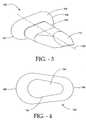
- FIG. 3is a perspective view of another embodiment of an implant in accordance with the present invention having a wing with a teardrop-shaped cross-section.
- FIG. 4is an end view of a second wing for use with the implant of FIG. 3 .
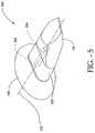
- FIG. 5is a perspective view of an embodiment of an implant in accordance with the present invention having a rotatable spacer and a wing with an elliptical cross-section.
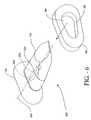
- FIG. 6is a perspective view of an embodiment of an implant in accordance with the present invention having a rotatable spacer with two wings that are teardrop-shaped in cross-section.
- FIG. 7depicts the axis of rotation of the implant of FIG. 6 as seen from an end view.
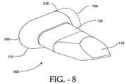
- FIG. 8is a perspective view of an embodiment of an implant in accordance with the present invention having a wing that is truncated at a posterior end.
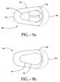
- FIG. 9Ais an end view of the implant of FIG. 8 .
- FIG. 9Bis a truncated second wing for use with the implant of FIG. 9A .
- FIG. 10is a plan view of an embodiment of an implant in accordance with the present invention wherein a screw is used to secure a second wing to the spacer.
- FIG. 11is a perspective view of the second wing of FIG. 10 .
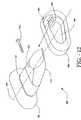
- FIG. 12is a perspective view of the implant of FIG. 10 .
- FIG. 13Ais a front view of a second wing for use with some embodiments of implants of the present invention having a flexible hinge mechanism for securing the second wing to an implant.
- FIG. 13Bis a side-sectional view of the second wing of FIG. 13A .
- FIG. 14Ais a plan view of an embodiment of an implant for use with the second wing of FIGS. 13A and 13B .
- FIG. 14Bis a front view of the second wing of FIGS. 13A and 13B .
- FIG. 15Ais a top view of an embodiment of an implant in accordance with the present invention positioned between spinous processes of adjacent cervical vertebrae.
- FIG. 15Bis a top view of the implant of FIG. 15A showing wing orientation.
- FIG. 16is a top view of two such implants of the invention of FIGS. 15A and 15B , positioned in the cervical spine.
- FIG. 17is a side view of two implants of the invention positioned in the cervical spine, with stops or keeps at the proximal ends of the spinous processes.
- FIG. 18is a perspective view of an alternative embodiment of an implant for use with systems and methods of the present invention, the implant including a slot formed in a portion of the distraction guide and a slotted anchor associated with the wing.
- FIG. 19Ais a top view of two such implants of the invention as seen in FIG. 18 , positioned between corresponding adjacent spinous processes, a strap being associated with one of the implants and being positioned around adjacent spinous processes.
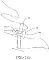
- FIG. 19Bis an end view of the implant of FIG. 18 positioned between adjacent spinous processes extending from respective cervical vertebrae.
- FIG. 19Cis an end view of the implant of FIG. 18 positioned between adjacent spinous processes extending from respective cervical vertebrae having a strap associated with the implant positioned through a portion of each of the spinous processes.
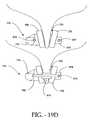
- FIG. 19Dis a top view of alternative implants having a bore formed in a portion of the distraction guide and in an anchor, a tether being associated with one of the implants and being positioned around adjacent spinous processes.
- FIG. 19Eis an end view of an implant, as shown in FIG. 19D .
- FIG. 20is a perspective view of still another embodiment of an implant for use with systems and methods of the present invention.
- FIG. 21Ais an end view of the implant of FIG. 20 positioned between adjacent spinous processes.
- FIG. 21Bis an end view of the implant of FIG. 20 showing an expansion portion of the spacer distracted.
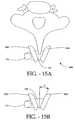
- FIG. 22Ais a partial cross-sectional posterior view of an embodiment of an implant for use with systems and methods of the present invention positioned between spinous processes, the implant having a spacer including an expansion portion.
- FIG. 22Bis a partial cross-sectional posterior view of the implant of FIG. 22A wherein the expansion portion is urged away from a main portion of the spacer.
- FIG. 22Cis a cross-sectional top view of the implant of FIGS. 22A and 22B .
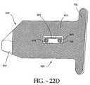
- FIG. 22Dis a cross-sectional top view of an implant in accordance with an alternative embodiment having tines for cojoining the expansion portion and main portion.
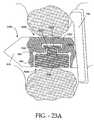
- FIG. 23Ais a partial cross-sectional posterior view of an alternative embodiment of an implant for use with systems and methods of the present invention positioned between spinous processes, the implant having a spacer including an expansion portion having a pliant stem.
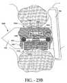
- FIG. 23Bis a partial cross-sectional posterior view of the implant of FIG. 23A wherein the expansion portion is urged away from a main portion of the spacer.
- FIG. 24Ais a partial cross-sectional posterior view of still another embodiment of an implant for use with systems and methods of the present invention positioned between spinous processes, the implant having a spacer including an expansion portion.
- FIG. 24Bis a partial cross-sectional posterior view of the implant of FIG. 24A wherein the expansion portion is urged away from a main portion of the spacer.
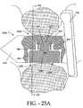
- FIG. 25Ais a partial cross-sectional posterior view of still another embodiment of an implant for use with systems and methods of the present invention positioned between spinous processes, the implant having a spacer including an expansion portion.
- FIG. 25Bis a partial cross-sectional posterior view of the implant of FIG. 25A showing an expansion portion of the spacer urged away from a main portion of the spacer.
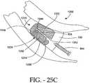
- FIG. 25Cis a cross-sectional end view of the implant of FIG. 25A including walls for slidably contacting adjacent spinous processes.
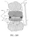
- FIG. 26Ais a partial cross-sectional posterior view of still another embodiment of an implant for use with systems and methods of the present invention positioned between spinous processes, the implant having a spacer including an expansion portion.
- FIG. 26Bis a partial cross-sectional posterior view of the implant of FIG. 26A wherein the expansion portion is urged away from a main portion of the spacer.
- FIG. 26Cis a cross-sectional end view of the implant of FIG. 26A .
- FIG. 27Ais a partial cross-sectional posterior view of still another embodiment of an implant for use with systems and methods of the present invention positioned between spinous processes, the implant having a spacer including an expansion portion.
- FIG. 27Bis a partial cross-sectional posterior view of the implant of FIG. 27A wherein the expansion portion is urged away from a main portion of the spacer.
- FIG. 28is a perspective view of a still further embodiment of an implant for use with systems and methods of the present invention, wherein a cavity for receiving an insert is accessible through a wing.
- FIG. 29illustrates an embodiment of a method for implanting an interspinous implant in accordance with the present invention.
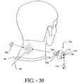
- FIG. 30illustrates an alternative embodiment of a method for implanting an interspinous implant including a binder in accordance with the present invention.
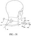
- FIG. 31illustrates an still another embodiment of a method for implanting an expandable interspinous implant in accordance with the present invention.
- FIGS. 1 and 2illustrate an implant 100 in accordance with an embodiment of the present invention.
- the implant 100comprises a wing 130 , a spacer 120 , and a lead-in tissue expander (also referred to herein as a distraction guide) 110 .
- the distraction guide 110in this particular embodiment is wedge-shaped, i.e., the implant has an expanding cross-section from a distal end of the implant 102 to a region 104 where the guide 110 joins with the spacer 120 (referencing for the figures is based on the point of insertion of the implant between spinous processes).
- the distraction guidefunctions to initiate distraction of the soft tissue and the spinous processes when the implant 100 is surgically inserted between the spinous processes.
- the distraction guide 110can be pointed and the like, in order to facilitate insertion of the implant 100 between the spinous processes of adjacent cervical vertebrae. It is advantageous that the insertion technique disturb as little of the bone and surrounding tissue or ligaments as possible in order to reduce trauma to the site and promote early healing, and prevent destabilization of the normal anatomy.
- the insertion techniquedisturb as little of the bone and surrounding tissue or ligaments as possible in order to reduce trauma to the site and promote early healing, and prevent destabilization of the normal anatomy.
- there is no requirement to remove any of the bone of the spinous processesand no requirement to sever or remove from the body ligaments and tissues immediately associated with the spinous processes. For example, it is unnecessary to sever the ligamentum nuchae (supraspinous ligament), which partially cushions the spinous processes of the upper cervical vertebrae.
- the spacer 120can be teardrop-shaped in cross-section perpendicular to a longitudinal axis 125 of the implant 100 .
- the shape of the spacer 120can roughly conform to a wedge-shaped space, or a portion of the space, between adjacent spinous processes within which the implant 100 is to be positioned.
- the spacer 120can have alternative shapes such as circular, wedge, elliptical, ovoid, football-shaped, and rectangular-shaped with rounded corners and other shapes, and be within the spirit and scope of the invention.
- the shape of the spacer 120can be selected for a particular patient so that the physician can position the implant 100 as close as possible to the anterior portion of the surface of the spinous process.
- the shape selected for the spacer 120can affect the contact surface area of the implant 100 and the spinous processes that are to be subject to distraction. Increasing the contact surface area between the implant 100 and the spinous processes can distribute the force and load between the spinous frame and the implant 100 .
- the wing 130 in an embodimentcan be elliptically shaped in cross-section perpendicular to the longitudinal axis 125 .
- the dimensions of the wing 130can be larger than that of the spacer 120 , particularly along the axis of the spine, and can limit or block lateral displacement of the implant 100 in the direction of insertion along the longitudinal axis 125 .
- the wing 130can alternatively have other cross-sectional shapes, such as teardrop, wedge, circular, ovoid, football-shaped, and rectangular-shaped with rounded corners and other shapes, and be within the spirit and scope of the invention.
- the wing 130has an anterior portion 138 and a posterior portion 136 .
- the implant 100can include two wings, with a second wing 160 (shown in FIG. 4 ) separate from the distraction guide 110 , spacer 120 and first wing 130 .
- the second wing 160can be connected to the distal end of the spacer 120 .
- the second wing 160similar to the first wing 130 , can limit or block lateral displacement of the implant 100 , however displacement is limited or blocked in the direction along the longitudinal axis 125 opposite insertion.
- both the first wing 130 and the second wing 160are connected with the implant 100 and the implant 100 is positioned between adjacent spinous processes, a portion of the spinous processes can be sandwiched between the first wing 130 and the second wing 160 , limiting any displacement along the longitudinal axis 125 .
- the second wing 160can be teardrop-shaped in cross-section.
- the wider end 166 of the second wing 160is the posterior end and the narrower end 168 of the second wing 160 is the anterior end.
- an opening 164is defined within the second wing 160 , the opening 164 being at least partially circumscribed by a lip 162 that allows the second wing 160 to pass over the distraction guide 110 to meet and connect with the spacer 120 .
- the second wing 160can be secured to the spacer 120 once the second wing 160 is properly positioned.
- the second wing 160can be connected with the implant after the implant 100 is positioned between the spinous processes.
- the implantcan be made in two pieces.
- the first piececan include the first wing 130 , the spacer 120 , and the distraction guide 110 .
- the second piececan include the second wing 160 .
- Each piececan be manufactured using technique known in the art (e.g., machining, molding, extrusion).
- Each pieceas will be more fully discussed below, can be made of a material that is bio-compatible with the body of the patient.
- An implantcan be formed with multiple pieces and with the pieces appropriately joined together, or alternatively, an implant can be formed as one piece or joined together as one piece.
- the spacer 220can be rotatable about the longitudinal axis 225 relative to the first wing 130 , or relative to the first wing 130 and a second wing 160 where two wings are used.
- the spacer 220can be rotatable or fixed relative to the distraction guide 110 .
- the spacer 220can include a bore 222 running the length of the longitudinal axis 225 , and a shaft 224 inserted through the bore 222 and connecting the distraction guide 110 with the first wing 130 .
- the rotatable spacer 220can rotate to conform to or settle between adjacent spinous processes as the implant 200 is inserted and positioned during implantation, so that on average the contact surface area between the spacer 220 and the spinous processes can be increased over the contact surface area between a fixed spacer 120 and the spinous processes.
- the rotatable spacer 220can improve the positioning of the spacer 220 independent of the wings 130 , 160 relative to the spinous processes.
- the embodiment of FIG. 6includes a teardrop-shaped first wing 130 , and a teardrop-shaped second wing 160 , similar to the second wing 160 depicted in the embodiment of FIG. 3 .
- the shape of the wings 130 , 160 in FIGS. 3 and 6is such that the implants 100 , 200 accommodate the twisting of the cervical spine along its axis, for example, as the head of a patient turns from side to side.
- FIG. 8is a perspective view and FIG. 9A is an end view of still another embodiment of an implant in accordance with the present invention, wherein the posterior portion 336 of the teardrop-shaped first wing 330 is truncated, making the first wing 330 more ovoid in shape.
- the anterior portion 138 of the first wing 330can be longer than the truncated posterior end 336 of the first wing 330 .
- the spacer 120can alternatively be a rotatable spacer rather than a fixed spacer.
- FIG. 9Billustrates a second wing 360 for use with such implants 300 , the second wing 360 having a truncated posterior end 366 .
- Truncation of the posterior ends 336 , 366 of the first and second wings 330 , 360can reduce the possibility of interference of implants 300 having such first and second wings 330 , 360 positioned between spinous processes of adjacent pairs of cervical vertebrae, e.g., implants between cervical vertebrae five and six, and between cervical vertebrae six and seven.
- the spinous processmove past each other in a scissor-like motion.
- Each cervical vertebracan rotate relative to the next adjacent cervical vertebra in the general range of about 6°-12°.
- about 50 percent of the rotational movement of the neckis accomplished by the top two neck vertebrae.
- such embodimentscan accommodate neck rotation without adjacent embodiments interfering with each other.
- the second wing 160can be designed to be interference-fit onto the spacer 120 (where the spacer is fixed) or a portion of the distraction guide 110 adjacent to the spacer 120 (where the spacer is rotatable). Where the second wing 160 is interference-fit, there is no additional attachment device to fasten the second wing 160 relative to the remainder of the implant. Alternatively, various fasteners can be used to secure the second wing relative to the remainder of the implant.
- FIGS. 10-12illustrate an embodiment of an implant 400 including a teardrop-shaped second wing 460 having a bore 463 through a tongue 461 at the posterior end of the second wing 460 .
- the bore 463is brought into alignment with a corresponding bore 440 on the spacer 120 when the second wing 460 is brought into position by surgical insertion relative to the rest of the implant 400 .
- a threaded screw 442can be inserted through the aligned bores 463 , 440 in a posterior-anterior direction to secure the second wing 460 to the spacer 120 .
- the direction of insertion from a posterior to an anterior directionhas the screw 442 engaging the bores 463 , 440 and the rest of the implant 400 along a direction that is generally perpendicular to the longitudinal axis 125 . This orientation is most convenient when the surgeon is required to use a screw 442 to secure the second wing 460 to the rest of the implant 400 .
- a rotatable spacer 220also can be accommodated by this embodiment. With a rotatable spacer 220 , the second wing 460 would be attached to a portion of the distraction guide 110 that is located adjacent to the rotatable spacer 220 .
- FIGS. 13A-14Bdepict a further embodiment 500 wherein the second wing 560 is secured to the spacer 120 by a mechanism including a flexible hinge 565 , with a protrusion 561 on the end of the hinge 565 adjacent to the lip 562 of the opening 564 defined by portions of the second wing 560 .
- the securing mechanismalso encompasses an indentation 540 on the spacer 120 , wherein the indentation 540 accommodates the protrusion 561 on the end of the flexible hinge 565 .
- the flexible hinge 565 and its protrusion 561deflect until the protrusion 561 meets and joins with the indentation 540 in the spacer 120 , securing the second wing 560 to the spacer 120 .
- the indentation 540is located on an end of the distraction guide 110 that is adjacent to the rotatable spacer 220 .
- this hingeis in a preferred embodiment formed with the second wing 560 and designed in such a way that it can flex as the hinge 565 is urged over the distraction guide 110 and the spacer 120 and then allow the protrusion 561 to be deposited into the indentation 540 .
- the indentation 540can exist in the second wing 560 and the flexible hinge 565 and the protrusion 561 can exist on the spacer 120 in order to mate the second wing 560 to the spacer 120 .
- the flexible hinge 565can be replaced with a flexible protrusion that can be flexed into engagement with the indentation 540 in the embodiment with the indentation 540 in the spacer 120 or in the embodiment with the indentation 540 in the second wing 560 .
- the second wingcan be mated with the implant.
- FIGS. 15A-16illustrate an embodiment of an implant 600 wherein anterior ends of a first wing 630 and second wing 660 flare out at an angle away from the spacer 120 and away from each other.
- the cervical spinous processesare themselves wedge-shaped when seen from a top view.
- the first wing 630 and second wing 660flare out so that the implant 600 can roughly conform with the wedge shape of the spinous processes, allowing the implant 600 to be positioned as close as possible to the vertebral bodies of the spine where the load of the spine is carried.
- the first and second wings 630 , 660are positioned relative to the spacer, whether the spacer is fixed 120 or rotatable 220 , so that the wings flare out as the wings approach the vertebral body of the spine.
- the first wing 630is aligned at an angle with respect to an axis along the spinous processes perpendicular to the longitudinal axis (also referred to herein as the plane of symmetry). In one embodiment, the angle is about 30°, however, the angle ⁇ can range from about 15° to about 45°. In other embodiments, other angles outside of this range are contemplated and in accordance with the invention.
- the second wing 660can be aligned along a similar, but oppositely varying range of angles relative to the plane of symmetry.
- the second wing 660defines an opening which is outlined by a lip.
- the lipcan be provided at an angle relative to the rest of the second wing 660 so that when the lip is urged into contact with the spacer 120 , the second wing 660 has the desired angle relative to the spacer 120 .
- FIG. 15Adepicts a top view of one such implant 600 placed between the spinous processes of adjacent cervical vertebrae.
- FIG. 16is a top view illustrating two layers of distracting implants 600 with flared wings 630 , 660 .
- FIG. 17illustrates “stops” (also referred to herein as “keeps”) 656 , which are rings of flexible biocompatible material, which can be positioned around the spinous processes of adjacent cervical vertebrae and located posteriorly to the implant 600 .
- the keeps 656can prevent posterior displacement of implants.
- the keepscan include a ring having a slit 658 .
- the keeps 656can be somewhat sprung apart, so that the keep 656 can be fit over the end of the spinous process and then allowed to spring back together in order to hold a position on the spinous process.
- the keep 656can act as a block to the spacer 120 in order to prevent the implant 600 from movement in a posterior direction.
- implants in accordance with the present inventioncan include a binder for engaging adjacent spinous processes, thereby limiting relative movement of the associated cervical vertebrae due to flexion.
- FIG. 18is a perspective view of one such implant.
- the implant 700resembles implants described above in reference to FIGS. 1-17 .
- the implant 700can have a shape different from those implants shown in FIGS. 1-17 .
- the implant 700can include a wing 730 , a spacer 720 , and a distraction guide 710 .
- the distraction guide 710 as shownis wedge-shaped, and can be pointed and the like, in order to facilitate insertion of the implant between the spinous processes of adjacent cervical vertebrae.
- the spacer 720is shaped to roughly conform to a wedge-like space, or a portion of the space, between adjacent spinous processes, for example as between the spinous processes of the sixth and seventh cervical vertebrae.
- the spacer 720includes a cross-section perpendicular to the spacer's longitudinal axis 725 that is roughly trapezoidal in shape and having rounded edges.
- the spacer 720 of FIG. 18is merely exemplary and as described above need not be shaped as shown.
- the shape of the spacer 720can be selected for a particular patient, and/or a particular pair of adjacent spinous processes, and can vary substantially.
- the spacer 720can have alternative cross-sectional shapes, such as teardrop, circular, wedge, elliptical, ovoid, football-shaped, rectangular-shaped with rounded corners, and other cross-sectional shapes and/or can be custom fabricated for a particular patient and an anatomy of the particular spinal processes between which the implant 700 is to be placed.
- the spacer 720can have a nonsymmetrical cross-sectional shape, for example where a space between adjacent spinous processes is nonsymmetrical.
- the ability to select a size and shape of the spacer 720 to suit a patientallows the physician to choose an implant 700 that can be placed closer to the vertebral bodies for additional support, rather than farther away from the vertebral bodies.
- the shape selected for the spacer 720can define the contact surface area between the implant 700 and the spinous processes that are subject to distraction. Increasing the contact surface area between the implant 700 and the spinous processes distributes the force and load between the spinal frame and the implant 700 .
- a teardrop, trapezoidal, or wedge-shaped spacer 720can allow for more load-bearing contact between the spacer 720 and the spinous processes of the cervical vertebrae, and embodiments having such shapes will be more particularly described.
- the implant 700 of FIG. 18can include a wing 730 having a dimension, at least along the spine, that is larger than the distracted space between the spinous processes, thereby limiting or blocking lateral displacement of the implant 700 in the direction of insertion along the longitudinal axis 725 .
- the wing 730 as shownhas a roughly trapezoidal shape with an upper edge that bulges so that the inner surface of the wing 730 arcs slightly.
- the variation in thickness of the wing 730can correspond, for example, with an estimated variation in width of the spinous process.
- the wing 730need not be shaped as shown.
- the wing 730can have some other shape, for example the wing 730 can be teardrop, elliptical, wedge, circular, ovoid, football-shaped, rectangular-shaped with rounded corners and other shapes, and be within the spirit and scope of the invention.
- the wing 730can alternatively have a nonsymmetrical cross-sectional shape.
- the shape of the wing 730can be chosen to most easily fit into place while avoiding obstructions, such as soft tissue or bone, or implants positioned between adjacent pairs of spinous processes, while still blocking or limiting lateral displacement. As shown in FIG. 18 , and further in FIGS.
- the wing 730can be arranged at an angle relative to one or both of an axis along the spine and a plane of symmetry S (also referred to herein as and axis along the spinous processes) so that the wing 730 roughly corresponds to a general shape of the spinous processes.
- the adjacent spinous processescan generally have a wedge shape.
- Such a general shapecan commonly be found in spinous processes extending from vertebrae of the cervical and thoracic region, for example.
- the wing 730can be arranged at an angle ⁇ that is about 30° relative to the plane of symmetry S; however, the angle ⁇ can range from about 15° to about 45°. In other embodiments, other angles of the first wing 730 relative to the spacer 720 outside of this range are contemplated and in accordance with the invention.
- the lower implant 700includes a binder 770 arranged around adjacent spinous processes (only the upper spinous process is shown).
- the distraction guide 710 and/or the spacer 720can include a slot 778 through which the binder 770 can be positioned.
- the distraction guide 710 and/or the spacer 720can include a bore 878 , or other cavity through which the binder 770 can be positioned (see FIG. 19D ).
- the slot 778is arranged so that the slot 778 is unobstructed by the spinous processes and so that the slot 778 is accessible to the binder 770 , when the binder 770 is surgically implanted.
- the slot 778can be included to limit shifting of the distal end of the implant 700 relative to the binder 770 , and to assist in keeping the binder 770 arranged as desired and as implanted.
- the implant 700can include an anchor 776 extending from the first wing 730 at a proximal end of the implant 700 .
- the anchor 776can include or form a slot 777 for receiving the binder 770 .
- the anchor 776 as shownincludes only a slot 777 .
- the binder 770can be knotted, sutured, clasped, or otherwise fixed in length to place the binder 770 in tension.
- the anchor 776can include a capture device such as a rotatable cam or clip for fixing the binder 770 in position.
- a capture devicesuch as a rotatable cam or clip for fixing the binder 770 in position.
- capture devicesare described in greater detailed in U.S. patent application Ser. No. 11/095,680, entitled “Interspinous Process Implant Including a Binder and Method of Implantation,” filed concurrently, and incorporated herein by reference.
- the binder 770can be threaded or passed through the slot 777 , and can be threaded through the interspinous ligaments of the adjacent spinous processes in order to engage the adjacent spinous processes.
- the implant 700can have two wings, with a second wing 760 separate from the distraction guide 710 , the spacer 720 and the first wing 730 .
- the second wing 760can be connected to the distal end of the spacer 720 . Similar to the first wing 730 , the second wing 760 can limit or block lateral displacement of the implant 700 , however displacement is limited or blocked in the direction opposite insertion.
- both the first wing 730 and the second wing 760are connected with the implant 700 and the implant 700 is positioned between adjacent spinous processes, as shown in FIGS. 19A and 19B , a portion of the spinous processes can be sandwiched between the first wing 730 and the second wing 760 , limiting any displacement along the longitudinal axis 725 .
- the second wing 760can be shaped roughly similar to the first wing 730 , but having a mirror-image orientation to accommodate a corresponding contour of the adjacent spinous processes. (Note that where the contour of the adjacent spinous processes is not symmetrical, the orientation may not be “mirror-image”.) In this way, the first wing 730 and second wing 760 form a wedge shape similar to the wedge shape formed by the spinous processes. Unlike the first wing 730 the sides of the second wing 760 defines an opening 764 which is circumscribed by a lip 762 that allows the second wing 760 to pass over the distraction guide 710 to meet and connect with the spacer 720 .
- the second wing 760is passed over the slot 778 formed in the distraction guide 710 and/or the spacer 720 so that the slot 778 is accessible when implanting the binder 770 .
- the second wing 760is then optionally secured to the spacer 720 toward the end of the spacer 720 located proximally from the first wing 730 .
- the second wing 760is connected with the implant 700 after the implant 700 is positioned between the spinous processes.
- the second wing 760can be aligned along a similar, but oppositely varying range of angles relative to the plane of symmetry S.
- the lip 762 of the opening 764can be provided at an angle relative to the rest of the second wing 760 so that when the lip 762 is urged into contact with the spacer 720 , the second wing 760 has the desired angle relative to the spacer 720 .
- the second wing 760need not be secured where a binder 770 passes through the slot 778 , as the binder 770 can prevent the second wing 760 from shifting in position.
- the second wing 760can be secured to the spacer 720 , as discussed above in reference to FIGS. 10-14B .
- the implant 700can be made in two pieces.
- the first piececan include the first wing 730 , the spacer 720 , and the distraction guide 710 .
- the second piececan include the second wing 760 .
- Each piececan be manufactured using technique known in the art (e.g., machining, molding, extrusion).
- Each pieceas will be more fully discussed below, can be made of a material that is bio-compatible with the body of the patient.
- An implantcan be formed with multiple pieces and with the pieces appropriately joined together, or alternatively, an implant can be formed as one piece or joined together as one piece.
- FIG. 19Bis an end view of an interspinous implant 700 positioned between adjacent spinous processes associated with the sixth and seventh cervical vertebrae.
- the implant 700is arranged so that the spacer 720 roughly fills a wedge-like space between the spinous processes.
- the second wing 760overlaps a portion of the spinous processes.
- a binder 770is positioned around the upper surface of the spinous process associated with the sixth vertebrae and positioned around the lower surface of the spinous process associated with the seventh vertebrae and placed in tension so that the binder 770 engages the adjacent spinous processes during flexion. By engaging the adjacent spinous processes, the binder 770 limits flexion.
- a physiciancan, if desired, alter a portion of bone from one or both of the adjacent spinous processes to receive the binder 770 , thereby ensuring that the adjacent spinous processes are engaged precisely during flexion of the spine.
- a slothas been cut or bored in each of the adjacent spinous processes, and a binder 770 is threaded through the spinous processes and the distraction guide 710 .
- the bindercan comprise a tether 872 .
- the anchor 876can include either a bore, a slot, or some other cavity through which the tether can pass and preferably (though not necessarily) be captured.
- the distraction guide 710 and/or the spacer 720can include either a bore 878 , a slot or some other cavity through which the tether 872 can pass and preferably be captured. Because the tether 872 engages a smaller surface area of the spinous processes, stress can be increased at points of contact.
- a load spreader 874(also referred to herein as a pad) made from a biologically compatible material can be associated with the tether 872 , and can protect the spinous processes from damage when the tether 872 restrains relative motion between the adjacent spinous processes. As can be seen in FIG. 19E , the load spreader 874 engages the upper surface and distributes the load applied by the tether 872 across a surface area roughly similar to the surface area contacted by the strap 870 of FIGS. 19A and 19B .
- the bindercan comprise a strap, ribbon, tether, cord, or some other flexible (or semi-flexible), and preferably threadable structure.
- the binder 770 , 870 , 872 and load spreader 874can be made from a biocompatible material.
- the binder 770 , 870 , 872 and load spreader 874can be made from a braided polyester suture material.
- Braided polyester suture materialsinclude, for example, Ethibond, Ethiflex, Mersilene, and Dacron, and are nonabsorbable, have high tensile strength, low tissue reactivity and improved handling.
- the binder 770 , 870 , 872 and load spreader 874can comprise stainless steel (i.e., surgical steel), which can be braided into a tether or woven into a strap, for example.
- the binder 770 , 870 , 872 and load spreader 874can made from some other material having similar desired properties.
- FIG. 20is a perspective view of one such implant 800 .
- the implant 800can include a spacer 820 , a first wing 730 , and a distraction guide 810 .
- the implant 800can further include a second wing 760 .
- the first wing 730 and the second wing 760are as described above in reference to FIG. 18 and can likewise vary in shape and arrangement.
- the spacer 820can include a main portion 822 and an expansion portion 826 that can be urged away from the main portion 822 by one or more inserts 854 (e.g., screws, wedges).
- the spacer 820can have an unexpanded cross-sectional shape resembling spacers described above in reference to FIGS. 1-18 . In other embodiments, the spacer 820 can have an unexpanded cross-sectional shape different from spacers described in reference to FIGS. 1-18 .
- the main portion 822 and the expansion portion 826can include contact surfaces (i.e., surfaces that contact and support a corresponding surface of a spinous process) having different shapes, thereby allowing the spacer to accommodate a geometry of the adjacent spinous processes between which the implant is to be placed.
- the expansion portion 826is positioned within a channel of the main portion 822 , and extends the depth of the spacer 820 along the spinous processes as well as across a substantial portion of the length of the spacer 820 so that the contact surface of one of the spinous processes contacts the expansion portion 826 .
- the contact surface of the expansion portion 826should not impede movement of the implant 800 into position between the adjacent spinous processes during surgery.
- the contact surface of the expansion portion 826is substantially aligned with a surface of the main portion 822 so that the expansion portion 826 does not protrude in such a way as to impede positioning of the implant 800 between spinous processes.
- the expansion portion 826is separatably connected with the main portion 822 by a stem, a hinge, or some other device.
- One or more grooves 850are disposed between the expansion portion 826 and the main portion 822 .
- the grooves 850are shaped to receive inserts 854 .
- the inserts 854are threaded screws
- the expanded grooves 850are shaped as threaded screw holes.
- the grooves 850do not have a continuous inner surface and when the spacer 820 is unexpanded, the grooves are at least partially collapsed.
- two inserts 854are associated with the implant 800 . Each of the inserts 854 is a threaded screw.
- the inserts 854can be any rigid structure capable of applying a force between the main portion 822 and the expansion portion 826 to urge the main portion 822 and expansion portion 826 apart.
- the insert 854can be a pin or a clip.
- the spacer 820includes a pair of threaded grooves 850 —one groove 850 formed at each corner where the expansion portion 826 meets the main portion 822 .
- the grooves 850are counter-sunk to receive a distal end of a corresponding threaded screw 854 , thereby allowing the threaded screw 854 to initiate distraction of the expansion portion 826 from the main portion 822 .
- the grooveexpands to accommodate the threaded screw 854 .
- Each groove 850must expand so that the expansion portion 826 is urged away from the main portion 822 .
- the overall height of the spacer 820 between the adjacent spinous processis expanded, distracting the adjacent spinous processes, and/or gripping the contact surface of the spinous process.
- FIG. 22Aa partial cross-section of an embodiment of an expandable implant 800 in accordance with the present invention is shown.
- the main portion 822includes a channel 840 having a bore 844 within which a stem 824 associated or connected with the expanded portion 826 is retained.
- the expanded portion 826is seated within the main portion 822 by an interference fit between holes 845 within a flange 823 of the stem 824 and a plurality of protrusions 846 of the main portion 822 .
- FIG. 22Cis a cross-sectional top view of the implant showing four protrusions 846 disposed within four holes 845 arranged about the flange 823 .
- the expansion portion 826 and main portion 822need not be cojoined as shown.
- the expansion portioncan include a stem 924 having prongs 945 for engaging protrusions 946 of the main portion 922 .
- the prongs 945are sized so that the protrusions 946 force the prongs 945 apart as the expansion portion 926 is seated within a cavity 944 (in this case, a cavity), creating an interference fit.
- a physiciancan optionally replace an expansion portion 826 with an expansion portion comprising, for example, a material having a different stiffness, or an expansion portion having a differently shaped contact surface more suitable to a patient's physiology.
- a physiciancan have a set of expansion portions, one of which can be selected to suit an individual patient's needs. In this sense, the expansion portion 826 can allow the implant to be customized for a patient.
- the expansion portion 826can comprise a rigid or semi-rigid shell 892 associated, connected, or integrally formed with the stem 824 .
- a grip 816can be positioned within the shell 892 and held, for example, by adhesion, an interference fit, or some other mechanism.
- the grip 816can be made of a deformable material, such as a polyketone or other thermoformable plastic, or the grip 816 can be made of a more pliant material, such as silicone. Such materials are described in greater detail below.
- a groove 850is disposed at each of the corners of the shell 892 . The grooves 850 are partially collapsed. Referring to FIG.
- the grip 816comprises a pliant material
- the grip 816at least partially reshapes as it contacts the corresponding spinous process and grips the spinous process, resisting relative movement between the implant 800 and the adjacent spinous processes. During expansion, the spinous processes can also be further distracted.
- FIGS. 23A and 23Bare partial cross-sections of an alternative embodiment of an expandable implant 1000 in accordance with the present invention.
- the main portion 1022includes a channel 840 having a bore 1044 .
- the bore 1044is necked so that a portion of the bore 1044 narrows in diameter near the opening to the channel 840 .
- the narrow portioncan be used to retain a stem 1024 of an expansion portion 1026 .
- the expansion portion 1026 in such embodimentscan comprise a rigid (or semi-rigid) ring 1090 around which the stem 1024 and a grip 1016 is formed.
- the ring 1090transfers a force applied by a pair of inserts 854 to the grip 1016 of the expansion portion 1026 so that the expansion portion 1026 distracts away from the inserts 854 rather than simply deforms around the inserts 854 (as may happen where the grip 1016 is made from a pliant material).
- the stem 1024is positioned within the bore 1044 , and is shaped so that a distal end of the stem 1024 includes a diameter wider than a diameter of the narrow portion of the bore 1044 . When an expansion force is not applied, the stem 1024 retains the expansion portion 1026 within the main portion 1022 .
- a groove 850is disposed on each side of the stem 1024 between the ring 1090 and the main portion 1022 .
- the grooves 850are partially collapsed. As the inserts 854 are mated and seated within the grooves 850 , the ring 1090 is forced away from the inserts 854 and consequently away from the main portion 1022 .
- the ring 1090applies a force to the grip 1016 that causes the stem 1024 to be flexed, as shown in FIG. 23B , and the grip 1016 at least partially reshapes around the contact surface of the corresponding spinous process.
- the expansion portion 1026grips the spinous process, resisting relative movement between the implant 1000 and the adjacent spinous processes.
- the grip 1016can be made of a pliant material to permit flexing, as described above and in further detail below.
- FIGS. 24A and 24Bare partial cross-sections of still another embodiment of an expandable implant 1100 in accordance with the present invention.
- Such an embodimentincludes two expansion portions 1126 , 1127 , each expansion portion 1126 , 1127 being arranged to contact a respective spinous process.
- the expansion portions 1126 , 1127each comprise a ring 1190 , 1191 and a grip 1116 , 1117 .
- the ring 1190 , 1191can be similar to the ring 1090 described with respect to FIGS. 23A and 23B , or the ring can be thinner to more easily flex (as shown in FIG. 24B ).
- a main portion 1122 of the spacer 1120includes two channels 1140 , 1142 formed within the spacer 1120 and a bore 1144 joining the channels 1140 , 1142 .
- the expansion portions 1126 , 1127are cojoined at the bore 1144 by a neck 1124 so that when no expansion force is applied, the expansion portions 1126 , 1127 have a contact surface substantially flush with an outer surface of the main portion 1122 .
- a groove 1150 , 1152 or other cavityis positioned along each of the corners of the expansion portions 1126 , 1127 , within the main portion 1122 . In other embodiments, more or fewer grooves can be formed and arranged to forcibly distract the expansion portions 1126 , 1127 from the main portion 1122 . As shown in FIG.
- the ring 1190 , 1191 of each expansion portion 1126 , 1127is forced away from the inserts 1154 , 1156 and away from the main portion 1122 .
- the expansion forcecauses the cojoined expansion portions 1126 , 1127 apart, and a neck 1124 cojoining the expansion portions 1126 , 1127 is stretched and thins.
- the grip 1116 , 1117 of the expansion portions 1126 , 1127can at least partially reshape themselves to conform to the respective spinous processes, and can grip the spinous processes, preventing shifting of the implant 1100 relative to the spinous processes.
- the grip 1116 , 1117can be made of a pliant material, as described above and in further detail below.
- FIGS. 25A and 25Bare partial cross-sections of a still further embodiment of an expandable implant 1200 in accordance with the present invention.
- the implant 1200resembles the implant of FIGS. 22A-22D in that the main portion 822 includes a channel 840 and a bore 844 formed within the channel 840 .
- One or more protrusions 846extend from within the bore 844 for forming an interference fit with a stem 824 of the expansion portion 1226 , as described above.
- the expansion portion 1226can comprise a rigid or semi-rigid structure 1292 associated, connected, or integrally formed with the stem 824 , and having a contact surface including a plurality of teeth 1214 .
- the main portion 822includes grooves 850 .
- the teeth 1214 of the expansion portion 1226can be embedded into, and/or can contactingly engage, a corresponding spinous process.
- the teeth 1214grab the surface and prevent relative shifting between the implant 1200 and the spinous processes.
- a main portion 1222include a cavity 1240 rather than a channel 840 , with the main portion 1222 including walls 1258 and with the expansion portion 1226 being slightly recessed within the cavity 1240 . In such an arrangement, surfaces of the walls 1258 slide along the contact surface of both spinous processes, preventing impedance of movement by teeth 1214 of the expansion portion 1226 .
- the expansion portion 1226can be urged away from the main portion 1222 .
- the walls 1258 of the main portion 1222can include holes 1262 through which an insert 854 can pass to mate and seat within a corresponding groove 850 .
- the expansion portion 1226can extend beyond the walls 1258 of the main portion 1222 , embedding (or contactingly engaging) the teeth 1214 of the expansion portion 1226 within the corresponding spinous process, thereby preventing shifting of the implant 1200 relative to the spinous processes.
- FIGS. 26A-26Care partial cross-sections of still another embodiment of an expandable implant 1300 in accordance with the present invention.
- a main portion 1322 of the spacer 1320can include a cavity 1340 within which is disposed an expansion portion 1326 .
- the expansion portion 1326can comprise a rigid or semi-rigid structure 1392 connected with the main portion 1322 by a hinge 1364 .
- the contact surface of the expansion portion 1326includes a plurality of teeth 1214 .
- the main portion 1322includes grooves 850 . As inserts 854 are positioned within the grooves 850 , an expansion force urges the expansion portion 1326 away from the main portion 1322 .
- the hinge 1364can bend at two hinge points 1366 , 1368 to yield to the expansion force, as shown in FIG. 26C .
- the teeth 1214 of the expansion portion 1326can be embedded into, or can contactingly engage, a corresponding spinous process.
- the teeth 1214grab the contact surface to prevent relative shifting between the implant 1300 and the spinous processes.
- the main portion 1322can include a cavity 1340 rather than a channel, with the main portion 1322 including walls 1258 and with the expansion portion 1326 being slightly recessed within the cavity 1340 , thereby preventing the teeth 1214 from possibly damaging the contact surface of the respective spinous process or associated tissues during implantation.
- FIG. 26CAn embodiment of a hinge 1364 can be seen in profile in FIG. 26C .
- the hinge 1364 as showninclude two hinge points 1366 , 1368 but in other embodiments can include more hinge points, similar to an accordion or bellows.
- the hinge 1364 as shown and describedis used with expansion portions 1326 including teeth 1214 , in other embodiments, a hinge 1364 can alternatively be used with an expansion portion 826 including a grip 816 , as described in previous embodiments. While stem arrangements and hinge arrangements have been described in detail, one of ordinary skill in the art will appreciate that other arrangements to urge a spacer to expand can be employed as well.
- FIGS. 27A and 27Bare cross-sections of a still further embodiment of an expandable implant 1400 in accordance with the present invention.
- a main portion 1422 of the spacer 1420includes a first channel 1440 and a second channel 1441 within which are disposed a first expansion portion 1426 and a second expansion portion 1427 , respectively.
- the expansion portion 1426 , 1427can comprise a rigid or semi-rigid structure 1492 , 1493 connected with the main portion 1422 by a hinge 1464 , 1465 .
- the contact surface of the first and second expansion portions 1426 , 1427include a plurality of teeth 1414 , 1415 .
- Two grooves 1150are positioned between the first expansion 1426 and the main portion 1422 and two grooves 1152 are positioned between the second expansion portion 1427 and the main portion 1422 .
- the teeth 1414 , 1415 of the expansion portion 1426 , 1427engage a corresponding spinous process.
- the teeth 1414 , 1415provide a grip for preventing relative shifting between the implant and the spinous processes.
- the main portion 1422can include a cavity rather than a channel, with the main portion 1422 including walls and with the expansion portions 1426 , 1427 being slightly recessed within the cavity, thereby preventing the teeth 1414 , 1415 from possibly damaging the contact surface of the respective spinous process or associated tissues during implantation.
- one or more grooves 1550can be formed parallel to the longitudinal axis of the implant 1500 , rather than perpendicular to the longitudinal axis L.
- An insert 1554can be positioned to distract the expansion portion 1526 using a lateral approach, that is to say an approach that is about perpendicular to a poster-to-anterior direction.
- a borecan be formed within the first wing 1530 having a diameter to accommodate the diameter of the insert 1554 .
- implants in accordance with embodiments of FIGS. 22-27can further include a binder to limit or block flexion of the adjacent vertebrae from which the spinous processes extend.
- the distraction guide 710 and/or the spacer 1520can include a slot 778 through which the binder can be positioned.
- An anchor 1576can extend from a proximal end of the implant 1500 , the anchor 1576 including a slot 1577 for receiving the binder.
- the anchor 1576 of FIG. 28is offset so as not to impede access to the groove 1550 by an insert 1554 .
- FIG. 18can have truncated wings as depicted in previous embodiments.
- the implant(except for the grip, where included) can be fabricated from medical grade metals such as titanium, stainless steel, cobalt chrome, and alloys thereof, or other suitable implant material having similar high strength and biocompatible properties. Additionally, the implant can be at least partially fabricated from a shape memory metal, for example Nitinol, which is a combination of titanium and nickel. Such materials are typically radiopaque, and appear during x-ray imaging, and other types of imaging. Implants in accordance with the present invention, and/or portions thereof can also be fabricated from somewhat flexible and/or deflectable material. In these embodiments, the implant and/or portions thereof can be fabricated in whole or in part from medical grade biocompatible polymers, copolymers, blends, and composites of polymers.
- medical grade metalssuch as titanium, stainless steel, cobalt chrome, and alloys thereof, or other suitable implant material having similar high strength and biocompatible properties.
- the implantcan be at least partially fabricated from a shape memory metal, for example Nitinol, which is a combination
- a copolymeris a polymer derived from more than one species of monomer.
- a polymer compositeis a heterogeneous combination of two or more materials, wherein the constituents are not miscible, and therefore exhibit an interface between one another.
- a polymer blendis a macroscopically homogeneous mixture of two or more different species of polymer.
- Many polymers, copolymers, blends, and composites of polymersare radiolucent and do not appear during x-ray or other types of imaging. Implants comprising such materials can provide a physician with a less obstructed view of the spine under imaging, than with an implant comprising radiopaque materials entirely. However, the implant need not comprise any radiolucent materials.
- biocompatible polymersare the polyaryl ester ketones which has several members including polyetheretherketone (PEEK), and polyetherketoneketone (PEKK).
- PEEKis proven as a durable material for implants, and meets the criterion of biocompatibility.
- Medical grade PEEKis available from Victrex Corporation of Lancashire, Great Britain under the product name PEEK-OPTIMA.
- Medical grade PEKKis available from Oxford Performance Materials under the name OXPEKK, and also from CoorsTek under the name BioPEKK. These medical grade materials are also available as reinforced polymer resins, such reinforced resins displaying even greater material strength.
- the implantcan be fabricated from PEEK 450G, which is an unfilled PEEK approved for medical implantation available from Victrex.
- PEEK 450Ghas the following approximate properties:
- the implant and/or portions thereofcan be formed by extrusion, injection, compression molding and/or machining techniques.
- Fillerscan be added to a polymer, copolymer, polymer blend, or polymer composite to reinforce a polymeric material. Fillers are added to modify properties such as mechanical, optical, and thermal properties. For example, carbon fibers can be added to reinforce polymers mechanically to enhance strength for certain uses, such as for load bearing devices.
- other grades of PEEKare available and contemplated for use in implants in accordance with the present invention, such as 30% glass-filled or 30% carbon-filled grades, provided such materials are cleared for use in implantable devices by the FDA, or other regulatory body. Glass-filled PEEK reduces the expansion rate and increases the flexural modulus of PEEK relative to unfilled PEEK.
- Carbon-filled PEEKis known to have enhanced compressive strength and stiffness, and a lower expansion rate relative to unfilled PEEK. Carbon-filled PEEK also offers wear resistance and load carrying capability.
- the implantcan be comprised of polyetherketoneketone (PEKK).
- PEKKpolyetherketoneketone
- Other material that can be usedinclude polyetherketone (PEK), polyetherketoneetherketoneketone (PEKEKK), polyetheretherketoneketone (PEEKK), and generally a polyaryletheretherketone.
- PEKpolyetherketone
- PEKEKKpolyetherketoneetherketoneketone
- PEEKKpolyetheretherketoneketone
- other polyketonescan be used as well as other thermoplastics.
- FIGS. 22A-24Bvarious embodiments of an expansion portion of a spacer include a grip.
- FIGS. 22A and 22Binclude a shell associated, connected or integrally formed with a stem. As shown, the shell can provide a frame for retaining a grip, or a plate to which the grip can be adhesively, or otherwise attached.
- FIGS. 23A-24Binclude rings surrounding a stem comprising a pliant material, and distributing a distraction force along the pliant material.
- the shell and ringscan be fabricated from similar materials as described above for the interspinous implant. It is within the scope of the invention that the shell and rings can comprise other shapes, as well.
- the gripcan be made of a pliant material, or in such embodiments where flexing is not required (e.g., FIGS. 22A-22D ), the grip can alternatively be made of a flexible or deformable material, such as medical grade biocompatible polymers, copolymers, blends, and composites of polymers.
- the shell and/or ringcan be made from a rigid material, such as a medical grade metal.
- the shell and/or ringcan be made from a rigid material, or alternatively from a flexible or deformable material.
- the pliant materialcan be selected to at least partially flex and/or deform when a tensile stress and/or compressive stress is applied to the pliant material.
- the pliant materialcan comprise silicone. It is within the scope of the present invention to manufacture the pliant material from other biologically acceptable, pliant material such as another polymer.
- the pliant materialcan comprise urethane-coated silicone and/or urethane co-formed with silicone so that the urethane will not be attacked by the body, or another ultra-high molecular weight polymer.
- polycarbonate-urethanea thermoplastic elastomer formed as the reaction product of a hydroxl terminated polycarbonate, an aromatic diisocyanate, and a low molecular weight glycol used as a chain extender.
- a preferred polycarbonate glycol intermediate, poly (1,6-hexyl 1,2-ethyl carbonate) diol, PHECDis the condensation product of 1,6-hexanediol with cyclic ethylene carbonate.
- the polycarbonate macro-glycolis reacted with aromatic isocyanate, 4,4′-methylene bisphenyl diisocyanate (MDI), and chain extended with 1,4-butanediol.
- MDI4,4′-methylene bisphenyl diisocyanate
- This materialis preferable used at a hardness of 55 durometer. This material, as well as the other materials, can be used in the other embodiments of the invention.
- the pliant materialcan further include a graduated stiffness to help gradually distribute the load when distraction of the shell or ring places a force upon the pliant material.
- a graduated stiffnesscan be at its lowest where the silicone contacts the spinous process, and the hardness of the silicone can be at its highest where the pliant material contacts the shell or ring.
- embodiments in accordance with the present inventioncan be constructed without a pliant material. It is also to be understood that the embodiments in accordance with the present invention can have other dimensions
- a minimally invasive surgical method for implanting an implant 400 in the cervical spineis disclosed and taught herein.
- a guide wire 80is inserted through a placement network or guide 90 into the neck of the implant recipient.
- the guide wire 80is used to locate where the implant is to be placed relative to the cervical spine, including the spinous processes.
- an incisionis made on the side of the neck so that an implant in accordance with an embodiment of the present invention, can be positioned in the neck thorough an incision and along a line that is about perpendicular to the guide wire 80 and directed at the end of the guide wire 80 .
- the implantcan be a sized implant 400 (i.e., having a body that is not distractable), such as described above in FIGS. 1-17 and including a distraction guide 110 , a spacer 120 , and a first wing 130 .
- the implant 400is inserted into the neck of the patient.
- the distraction guide 110pierces or separates the tissue without severing the tissue.
- a second wing 460can be optionally inserted along a line that is generally colinear with the line over which the implant 400 is inserted but from the opposite side of the neck.
- the anatomy of the neckis such that it is most convenient and minimally invasive to enter the neck from the side with respect to the implant 400 and the second wing 460 .
- the second wing 460is mated to the implant and in this particular embodiment, the second wing 460 is attached to the implant 400 by the use of a fastener, for example by a screw 442 . Where a screw is used, the screw 442 can be positioned using a screw driving mechanism that is directed along a posterior to anterior line somewhat parallel to the guide wire 80 .
- the second wing 460is positioned so that a bore 463 formed in a lip 461 of the second wing 460 is aligned with a bore 440 of the implant 400 , as described above.
- the screw 442is positioned within both bores and secured, at least, to the bore 440 of the implant 400 .
- the second wingcan be interference fit with the implant, as described above, or fastened using some other mechanism, such as a flexible hinge and protrusion.
- the implantcan include a binder, such as described above in FIGS. 18-19B .
- a guide wire 80is inserted through a placement network or guide 90 into the neck of the implant recipient (as shown and described above).
- an incisionis made on the side of the neck so that an implant 700 in accordance with an embodiment of the present invention can be positioned in the neck thorough an incision and along a line that is about perpendicular to the guide wire 80 and directed at the end of the guide wire.
- the implant 700can include a distraction guide 710 , a spacer 720 , and a first wing 730 .
- the implant 700is inserted into the neck of the patient, between adjacent spinous processes.
- the distraction guide 710pierces or separates the tissue without severing the tissue, and the implant 700 is positioned so that the spacer 720 is between the adjacent spinous processes.
- a second wing 760can optionally be inserted along a line that is generally colinear with the line over which the implant 700 is inserted but from the opposite side of the neck.
- the anatomy of the neckis such that it is most convenient and minimally invasive to enter the neck from the side with respect to the implant 700 and the second wing 760 .
- the second wing 760can be mated to the implant 700 through an interference fit, or alternatively by attaching to one of the distraction guide 710 and the spacer 720 by the use of a fastener, or by some other device, as described above.
- the screwcan be positioned using a screw driving mechanism that is directed along a posterior to anterior line somewhat parallel to the guide wire. This posterior to anterior line aids the physician in viewing and securing the second wing 760 to the implant 700 .
- the implant 700further includes an anchor 776 extending from the first wing 730 .
- the anchor 776includes or defines a slot 777 .
- One or both of the distraction guide 710 and the spacer 720includes a slot 778 as well.
- a distal end of the binder 770can be associated with a surgical needle which facilitates threading the binder 770 , but which can be removed once the binder is properly arranged about the spinous processes.
- the distal end of the binder 770can then be knotted, sutured, or otherwise fixed with a proximal end of the binder 770 so that the binder 770 is placed under tension.
- the anchor 776comprises a capture device, such as a rotatable cam
- the binder 770can be fixed to the capture device or first wing 730 .
- the binder 770limits flexion movement and can assists in maintaining the position of the implant 700 between the spinous processes.
- the implantcan be an expandable implant 1500 , such as described above in FIGS. 20-28 .
- a guide wire 80is inserted through a placement network 90 into the neck of the implant recipient (as shown and described above).
- an incisionis made on the side of the neck so that an expandable implant 1500 in accordance with an embodiment of the present invention, can be positioned in the neck thorough an incision and along a line that is about perpendicular to the guide wire 80 and directed at the end of the guide wire.
- the expandable implant 1500can include a distraction guide 1510 , a spacer 1520 , and a first wing 1530 .
- the implant 1500is inserted into the neck of the patient, between adjacent spinous processes.
- the distraction guide 1510pierces or separates the tissue without severing the tissue, and the implant 1500 is positioned so that the spacer 1520 is between the adjacent spinous processes.
- An insert 1554is then positioned within the incision and urged into a groove 1550 positioned between an expansion portion 1526 of the spacer 1520 and a main portion 1522 of the spacer 1520 .
- the insert 1554as shown in a threaded screw. As the insert 1554 engages threads of the groove 1550 and becomes seated within the groove 1550 , the expansion portion 1526 is distracted away from the main portion 1522 , thereby expanding the implant 1500 .
- a second wing 1560can optionally be inserted along a line that is generally colinear with the line over which the implant 1500 is inserted but from the opposite side of the neck. It is to be understood that the second wing 1560 can be implanted alternatively prior to the expansion step.
- the anatomy of the neckis such that it is most convenient and minimally invasive to enter the neck from the side with respect to the implant 1500 and the second wing 1560 .
- the second wing 1560can be mated to the implant 1500 through an interference fit, or alternatively by attaching to one of the distraction guide 1510 and the spacer 1520 by the use of a fastener, or by some other device, as described above.
- the screwcan be positioned using a screw driving mechanism that is directed along a posterior to anterior line somewhat parallel to the guide wire. This posterior to anterior line aids the physician in viewing and securing the second wing 1560 to the implant 1500 . While the method has been described as including associating the second wing 1560 with the implant 1500 after the implant 1500 has been expanded, in other embodiments the second wing 1560 can be connected with the implant 1500 prior to expansion.
Landscapes
- Health & Medical Sciences (AREA)
- Orthopedic Medicine & Surgery (AREA)
- Life Sciences & Earth Sciences (AREA)
- Neurology (AREA)
- Surgery (AREA)
- Heart & Thoracic Surgery (AREA)
- Engineering & Computer Science (AREA)
- Biomedical Technology (AREA)
- Nuclear Medicine, Radiotherapy & Molecular Imaging (AREA)
- Medical Informatics (AREA)
- Molecular Biology (AREA)
- Animal Behavior & Ethology (AREA)
- General Health & Medical Sciences (AREA)
- Public Health (AREA)
- Veterinary Medicine (AREA)
- Prostheses (AREA)
Abstract
Description
| Property | Value | ||
| Density | 1.3 | g/cc | ||
| Rockwell M | 99 | |||
| Rockwell R | 126 | |||
| Tensile Strength | 97 | MPa | ||
| Modulus of Elasticity | 3.5 | GPa | ||
| Flexural Modulus | 4.1 | GPa | ||
PEEK 450G has appropriate physical and mechanical properties and is suitable for carrying and spreading a physical load between the adjacent spinous processes. The implant and/or portions thereof can be formed by extrusion, injection, compression molding and/or machining techniques.
Claims (16)
Priority Applications (15)
| Application Number | Priority Date | Filing Date | Title |
|---|---|---|---|
| US11/234,555US8048117B2 (en) | 2003-05-22 | 2005-09-23 | Interspinous process implant and method of implantation |
| US11/806,526US8221463B2 (en) | 2002-10-29 | 2007-05-31 | Interspinous process implants and methods of use |
| US11/806,528US20080021468A1 (en) | 2002-10-29 | 2007-05-31 | Interspinous process implants and methods of use |
| US11/768,222US8092535B2 (en) | 2002-10-29 | 2007-06-26 | Interspinous process implants and methods of use |
| US11/768,224US20080065213A1 (en) | 2002-10-29 | 2007-06-26 | Interspinous process implants and methods of use |
| US11/768,223US20080065212A1 (en) | 2002-10-29 | 2007-06-26 | Interspinous process implants and methods of use |
| US11/770,934US20080221692A1 (en) | 2002-10-29 | 2007-06-29 | Interspinous process implants and methods of use |
| US11/770,924US20080046081A1 (en) | 2002-10-29 | 2007-06-29 | Interspinous process implants and methods of use |
| US11/771,046US20080051899A1 (en) | 2002-10-29 | 2007-06-29 | Interspinous process implants and methods of use |
| US11/770,943US20080051898A1 (en) | 2002-10-29 | 2007-06-29 | Interspinous process implants and methods of use |
| US11/771,092US8454659B2 (en) | 2002-10-29 | 2007-06-29 | Interspinous process implants and methods of use |
| US11/770,931US20080065214A1 (en) | 2002-10-29 | 2007-06-29 | Interspinous process implants and methods of use |
| US11/770,915US8007537B2 (en) | 2002-10-29 | 2007-06-29 | Interspinous process implants and methods of use |
| US11/771,099US7662187B2 (en) | 2002-10-29 | 2007-06-29 | Interspinous process implants and methods of use |
| US11/771,087US8894686B2 (en) | 2002-10-29 | 2007-06-29 | Interspinous process implants and methods of use |
Applications Claiming Priority (4)
| Application Number | Priority Date | Filing Date | Title |
|---|---|---|---|
| US47281703P | 2003-05-22 | 2003-05-22 | |
| US10/850,267US7695513B2 (en) | 2003-05-22 | 2004-05-20 | Distractible interspinous process implant and method of implantation |
| US61258204P | 2004-09-23 | 2004-09-23 | |
| US11/234,555US8048117B2 (en) | 2003-05-22 | 2005-09-23 | Interspinous process implant and method of implantation |
Related Parent Applications (1)
| Application Number | Title | Priority Date | Filing Date |
|---|---|---|---|
| US10/850,267Continuation-In-PartUS7695513B2 (en) | 2002-10-29 | 2004-05-20 | Distractible interspinous process implant and method of implantation |
Related Child Applications (3)
| Application Number | Title | Priority Date | Filing Date |
|---|---|---|---|
| US10/694,103Continuation-In-PartUS20050075634A1 (en) | 2002-10-29 | 2003-10-27 | Interspinous process implant with radiolucent spacer and lead-in tissue expander |
| US11/806,526Continuation-In-PartUS8221463B2 (en) | 2002-10-29 | 2007-05-31 | Interspinous process implants and methods of use |
| US11/806,528Continuation-In-PartUS20080021468A1 (en) | 2002-10-29 | 2007-05-31 | Interspinous process implants and methods of use |
Publications (2)
| Publication Number | Publication Date |
|---|---|
| US20060089718A1 US20060089718A1 (en) | 2006-04-27 |
| US8048117B2true US8048117B2 (en) | 2011-11-01 |
Family
ID=36207127
Family Applications (1)
| Application Number | Title | Priority Date | Filing Date |
|---|---|---|---|
| US11/234,555Expired - Fee RelatedUS8048117B2 (en) | 2002-10-29 | 2005-09-23 | Interspinous process implant and method of implantation |
Country Status (1)
| Country | Link |
|---|---|
| US (1) | US8048117B2 (en) |
Cited By (29)
| Publication number | Priority date | Publication date | Assignee | Title |
|---|---|---|---|---|
| US8636771B2 (en) | 2010-11-29 | 2014-01-28 | Life Spine, Inc. | Spinal implants for lumbar vertebra to sacrum fixation |
| US8864828B2 (en) | 2004-10-20 | 2014-10-21 | Vertiflex, Inc. | Interspinous spacer |
| US8900271B2 (en) | 2004-10-20 | 2014-12-02 | The Board Of Trustees Of The Leland Stanford Junior University | Systems and methods for posterior dynamic stabilization of the spine |
| US8940048B2 (en) | 2005-03-31 | 2015-01-27 | Life Spine, Inc. | Expandable spinal interbody and intravertebral body devices |
| US9034041B2 (en) | 2005-03-31 | 2015-05-19 | Life Spine, Inc. | Expandable spinal interbody and intravertebral body devices |
| US9039742B2 (en) | 2004-10-20 | 2015-05-26 | The Board Of Trustees Of The Leland Stanford Junior University | Systems and methods for posterior dynamic stabilization of the spine |
| US9119680B2 (en) | 2004-10-20 | 2015-09-01 | Vertiflex, Inc. | Interspinous spacer |
| US9149306B2 (en) | 2011-06-21 | 2015-10-06 | Seaspine, Inc. | Spinous process device |
| US9155570B2 (en) | 2004-10-20 | 2015-10-13 | Vertiflex, Inc. | Interspinous spacer |
| US9301788B2 (en) | 2008-04-10 | 2016-04-05 | Life Spine, Inc. | Adjustable spine distraction implant |
| US9381050B2 (en) | 2007-04-10 | 2016-07-05 | Life Spine, Inc. | Adjustable spine distraction implant |
| US9498560B2 (en) | 2011-03-04 | 2016-11-22 | Spinefrontier, Inc | Interspinous spacer implant |
| US9662150B1 (en) | 2007-02-26 | 2017-05-30 | Nuvasive, Inc. | Spinal stabilization system and methods of use |
| US9801733B2 (en) | 2005-03-31 | 2017-10-31 | Life Spine, Inc. | Expandable spinal interbody and intravertebral body devices |
| US10154911B2 (en) | 2013-03-13 | 2018-12-18 | Life Spine, Inc. | Expandable implant assembly |
| US10335207B2 (en) | 2015-12-29 | 2019-07-02 | Nuvasive, Inc. | Spinous process plate fixation assembly |
| US10383741B2 (en) | 2013-03-13 | 2019-08-20 | Life Spine, Inc. | Expandable spinal interbody assembly |
| US10426632B2 (en) | 2013-03-13 | 2019-10-01 | Life Spine, Inc. | Expandable spinal interbody assembly |
| US11033403B2 (en) | 2017-07-10 | 2021-06-15 | Life Spine, Inc. | Expandable implant assembly |
| US11304818B2 (en) | 2013-03-13 | 2022-04-19 | Life Spine, Inc. | Expandable spinal interbody assembly |
| US11382764B2 (en) | 2019-06-10 | 2022-07-12 | Life Spine, Inc. | Expandable implant assembly with compression features |
| US11602440B2 (en) | 2020-06-25 | 2023-03-14 | Life Spine, Inc. | Expandable implant assembly |
| US11602439B2 (en) | 2020-04-16 | 2023-03-14 | Life Spine, Inc. | Expandable implant assembly |
| US11857432B2 (en) | 2020-04-13 | 2024-01-02 | Life Spine, Inc. | Expandable implant assembly |
| US11896494B2 (en) | 2017-07-10 | 2024-02-13 | Life Spine, Inc. | Expandable implant assembly |
| US12042395B2 (en) | 2019-06-11 | 2024-07-23 | Life Spine, Inc. | Expandable implant assembly |
| US12193948B2 (en) | 2013-03-13 | 2025-01-14 | Life Spine, Inc. | Expandable implant assembly |
| US12336917B2 (en) | 2020-05-15 | 2025-06-24 | Life Spine, Inc. | Steerable implant assembly |
| US12364610B2 (en) | 2020-09-08 | 2025-07-22 | Life Spine, Inc. | Expandable implant with pivoting control assembly |
Families Citing this family (93)
| Publication number | Priority date | Publication date | Assignee | Title |
|---|---|---|---|---|
| US5836948A (en)* | 1997-01-02 | 1998-11-17 | Saint Francis Medical Technologies, Llc | Spine distraction implant and method |
| US6068630A (en)* | 1997-01-02 | 2000-05-30 | St. Francis Medical Technologies, Inc. | Spine distraction implant |
| US20060064165A1 (en)* | 2004-09-23 | 2006-03-23 | St. Francis Medical Technologies, Inc. | Interspinous process implant including a binder and method of implantation |
| AU2004212942A1 (en) | 2003-02-14 | 2004-09-02 | Depuy Spine, Inc. | In-situ formed intervertebral fusion device |
| FR2851154B1 (en)* | 2003-02-19 | 2006-07-07 | Sdgi Holding Inc | INTER-SPINOUS DEVICE FOR BRAKING THE MOVEMENTS OF TWO SUCCESSIVE VERTEBRATES, AND METHOD FOR MANUFACTURING THE SAME THEREOF |
| US8425559B2 (en) | 2004-10-20 | 2013-04-23 | Vertiflex, Inc. | Systems and methods for posterior dynamic stabilization of the spine |
| US8277488B2 (en) | 2004-10-20 | 2012-10-02 | Vertiflex, Inc. | Interspinous spacer |
| US8123807B2 (en)* | 2004-10-20 | 2012-02-28 | Vertiflex, Inc. | Systems and methods for posterior dynamic stabilization of the spine |
| US8012207B2 (en) | 2004-10-20 | 2011-09-06 | Vertiflex, Inc. | Systems and methods for posterior dynamic stabilization of the spine |
| US9161783B2 (en) | 2004-10-20 | 2015-10-20 | Vertiflex, Inc. | Interspinous spacer |
| US8317864B2 (en) | 2004-10-20 | 2012-11-27 | The Board Of Trustees Of The Leland Stanford Junior University | Systems and methods for posterior dynamic stabilization of the spine |
| US8409282B2 (en) | 2004-10-20 | 2013-04-02 | Vertiflex, Inc. | Systems and methods for posterior dynamic stabilization of the spine |
| US7763074B2 (en)* | 2004-10-20 | 2010-07-27 | The Board Of Trustees Of The Leland Stanford Junior University | Systems and methods for posterior dynamic stabilization of the spine |
| US8945183B2 (en) | 2004-10-20 | 2015-02-03 | Vertiflex, Inc. | Interspinous process spacer instrument system with deployment indicator |
| US8128662B2 (en) | 2004-10-20 | 2012-03-06 | Vertiflex, Inc. | Minimally invasive tooling for delivery of interspinous spacer |
| US8123782B2 (en) | 2004-10-20 | 2012-02-28 | Vertiflex, Inc. | Interspinous spacer |
| US8613747B2 (en) | 2004-10-20 | 2013-12-24 | Vertiflex, Inc. | Spacer insertion instrument |
| US9023084B2 (en) | 2004-10-20 | 2015-05-05 | The Board Of Trustees Of The Leland Stanford Junior University | Systems and methods for stabilizing the motion or adjusting the position of the spine |
| US8241330B2 (en)* | 2007-01-11 | 2012-08-14 | Lanx, Inc. | Spinous process implants and associated methods |
| US9055981B2 (en) | 2004-10-25 | 2015-06-16 | Lanx, Inc. | Spinal implants and methods |
| WO2006058221A2 (en) | 2004-11-24 | 2006-06-01 | Abdou Samy M | Devices and methods for inter-vertebral orthopedic device placement |
| EP2219538B1 (en) | 2004-12-06 | 2022-07-06 | Vertiflex, Inc. | Spacer insertion instrument |
| US8366773B2 (en) | 2005-08-16 | 2013-02-05 | Benvenue Medical, Inc. | Apparatus and method for treating bone |
| WO2008103781A2 (en) | 2007-02-21 | 2008-08-28 | Benvenue Medical, Inc. | Devices for treating the spine |
| AU2006279558B2 (en) | 2005-08-16 | 2012-05-17 | Izi Medical Products, Llc | Spinal tissue distraction devices |
| US7862592B2 (en)* | 2005-12-06 | 2011-01-04 | Nuvasive, Inc. | Methods and apparatus for treating spinal stenosis |
| US8083795B2 (en)* | 2006-01-18 | 2011-12-27 | Warsaw Orthopedic, Inc. | Intervertebral prosthetic device for spinal stabilization and method of manufacturing same |
| US8845726B2 (en) | 2006-10-18 | 2014-09-30 | Vertiflex, Inc. | Dilator |
| WO2008070863A2 (en) | 2006-12-07 | 2008-06-12 | Interventional Spine, Inc. | Intervertebral implant |
| US20080167655A1 (en)* | 2007-01-05 | 2008-07-10 | Jeffrey Chun Wang | Interspinous implant, tools and methods of implanting |
| US8974496B2 (en)* | 2007-08-30 | 2015-03-10 | Jeffrey Chun Wang | Interspinous implant, tools and methods of implanting |
| US9265532B2 (en) | 2007-01-11 | 2016-02-23 | Lanx, Inc. | Interspinous implants and methods |
| US9247968B2 (en) | 2007-01-11 | 2016-02-02 | Lanx, Inc. | Spinous process implants and associated methods |
| EP2124778B1 (en) | 2007-02-21 | 2019-09-25 | Benvenue Medical, Inc. | Devices for treating the spine |
| AU2008241447B2 (en) | 2007-04-16 | 2014-03-27 | Vertiflex, Inc. | Interspinous spacer |
| US8142479B2 (en)* | 2007-05-01 | 2012-03-27 | Spinal Simplicity Llc | Interspinous process implants having deployable engagement arms |
| EP2142146A4 (en)* | 2007-05-01 | 2010-12-01 | Spinal Simplicity Llc | Interspinous implants and methods for implanting same |
| US8070779B2 (en)* | 2007-06-04 | 2011-12-06 | K2M, Inc. | Percutaneous interspinous process device and method |
| US8900307B2 (en) | 2007-06-26 | 2014-12-02 | DePuy Synthes Products, LLC | Highly lordosed fusion cage |
| US8308767B2 (en) | 2007-09-19 | 2012-11-13 | Pioneer Surgical Technology, Inc. | Interlaminar stabilization system |
| US20090105773A1 (en)* | 2007-10-23 | 2009-04-23 | Warsaw Orthopedic, Inc. | Method and apparatus for insertion of an interspinous process device |
| EP2237748B1 (en) | 2008-01-17 | 2012-09-05 | Synthes GmbH | An expandable intervertebral implant |
| US8202299B2 (en)* | 2008-03-19 | 2012-06-19 | Collabcom II, LLC | Interspinous implant, tools and methods of implanting |
| US8936641B2 (en) | 2008-04-05 | 2015-01-20 | DePuy Synthes Products, LLC | Expandable intervertebral implant |
| WO2010085809A1 (en) | 2009-01-26 | 2010-07-29 | Life Spine, Inc. | Flexible and static interspinous/inter-laminar spinal spacers |
| US10052139B2 (en) | 2009-01-26 | 2018-08-21 | Life Spine, Inc. | Flexible and static interspinous/inter-laminar spinal spacers |
| US9861399B2 (en) | 2009-03-13 | 2018-01-09 | Spinal Simplicity, Llc | Interspinous process implant having a body with a removable end portion |
| US8945184B2 (en)* | 2009-03-13 | 2015-02-03 | Spinal Simplicity Llc. | Interspinous process implant and fusion cage spacer |
| US9757164B2 (en) | 2013-01-07 | 2017-09-12 | Spinal Simplicity Llc | Interspinous process implant having deployable anchor blades |
| US8535327B2 (en) | 2009-03-17 | 2013-09-17 | Benvenue Medical, Inc. | Delivery apparatus for use with implantable medical devices |
| US9526620B2 (en) | 2009-03-30 | 2016-12-27 | DePuy Synthes Products, Inc. | Zero profile spinal fusion cage |
| US8764806B2 (en) | 2009-12-07 | 2014-07-01 | Samy Abdou | Devices and methods for minimally invasive spinal stabilization and instrumentation |
| US9393129B2 (en) | 2009-12-10 | 2016-07-19 | DePuy Synthes Products, Inc. | Bellows-like expandable interbody fusion cage |
| US8740948B2 (en) | 2009-12-15 | 2014-06-03 | Vertiflex, Inc. | Spinal spacer for cervical and other vertebra, and associated systems and methods |
| US8979860B2 (en) | 2010-06-24 | 2015-03-17 | DePuy Synthes Products. LLC | Enhanced cage insertion device |
| US9907560B2 (en) | 2010-06-24 | 2018-03-06 | DePuy Synthes Products, Inc. | Flexible vertebral body shavers |
| US8623091B2 (en) | 2010-06-29 | 2014-01-07 | DePuy Synthes Products, LLC | Distractible intervertebral implant |
| US9402732B2 (en) | 2010-10-11 | 2016-08-02 | DePuy Synthes Products, Inc. | Expandable interspinous process spacer implant |
| US8721687B2 (en)* | 2010-11-29 | 2014-05-13 | Life Spine, Inc. | Spinal implant for lumbar vertebra to sacrum fixation |
| US8496689B2 (en) | 2011-02-23 | 2013-07-30 | Farzad Massoudi | Spinal implant device with fusion cage and fixation plates and method of implanting |
| US8425560B2 (en) | 2011-03-09 | 2013-04-23 | Farzad Massoudi | Spinal implant device with fixation plates and lag screws and method of implanting |
| KR101066324B1 (en)* | 2011-04-06 | 2011-09-20 | 유창화 | Spinal process spacer |
| US8814873B2 (en) | 2011-06-24 | 2014-08-26 | Benvenue Medical, Inc. | Devices and methods for treating bone tissue |
| US8845728B1 (en) | 2011-09-23 | 2014-09-30 | Samy Abdou | Spinal fixation devices and methods of use |
| US11812923B2 (en) | 2011-10-07 | 2023-11-14 | Alan Villavicencio | Spinal fixation device |
| US20130226240A1 (en) | 2012-02-22 | 2013-08-29 | Samy Abdou | Spinous process fixation devices and methods of use |
| US9198767B2 (en) | 2012-08-28 | 2015-12-01 | Samy Abdou | Devices and methods for spinal stabilization and instrumentation |
| US9320617B2 (en) | 2012-10-22 | 2016-04-26 | Cogent Spine, LLC | Devices and methods for spinal stabilization and instrumentation |
| US9717601B2 (en) | 2013-02-28 | 2017-08-01 | DePuy Synthes Products, Inc. | Expandable intervertebral implant, system, kit and method |
| US9522070B2 (en) | 2013-03-07 | 2016-12-20 | Interventional Spine, Inc. | Intervertebral implant |
| US10085783B2 (en) | 2013-03-14 | 2018-10-02 | Izi Medical Products, Llc | Devices and methods for treating bone tissue |
| US9675303B2 (en) | 2013-03-15 | 2017-06-13 | Vertiflex, Inc. | Visualization systems, instruments and methods of using the same in spinal decompression procedures |
| AU2015256024B2 (en) | 2014-05-07 | 2020-03-05 | Vertiflex, Inc. | Spinal nerve decompression systems, dilation systems, and methods of using the same |
| US11426290B2 (en) | 2015-03-06 | 2022-08-30 | DePuy Synthes Products, Inc. | Expandable intervertebral implant, system, kit and method |
| US10857003B1 (en) | 2015-10-14 | 2020-12-08 | Samy Abdou | Devices and methods for vertebral stabilization |
| EP3474784A2 (en) | 2016-06-28 | 2019-05-01 | Eit Emerging Implant Technologies GmbH | Expandable and angularly adjustable intervertebral cages with articulating joint |
| US11510788B2 (en) | 2016-06-28 | 2022-11-29 | Eit Emerging Implant Technologies Gmbh | Expandable, angularly adjustable intervertebral cages |
| US10744000B1 (en) | 2016-10-25 | 2020-08-18 | Samy Abdou | Devices and methods for vertebral bone realignment |
| US10973648B1 (en) | 2016-10-25 | 2021-04-13 | Samy Abdou | Devices and methods for vertebral bone realignment |
| US10888433B2 (en) | 2016-12-14 | 2021-01-12 | DePuy Synthes Products, Inc. | Intervertebral implant inserter and related methods |
| US10398563B2 (en) | 2017-05-08 | 2019-09-03 | Medos International Sarl | Expandable cage |
| US11344424B2 (en) | 2017-06-14 | 2022-05-31 | Medos International Sarl | Expandable intervertebral implant and related methods |
| US10940016B2 (en) | 2017-07-05 | 2021-03-09 | Medos International Sarl | Expandable intervertebral fusion cage |
| US11179248B2 (en) | 2018-10-02 | 2021-11-23 | Samy Abdou | Devices and methods for spinal implantation |
| US11446156B2 (en) | 2018-10-25 | 2022-09-20 | Medos International Sarl | Expandable intervertebral implant, inserter instrument, and related methods |
| US11426286B2 (en) | 2020-03-06 | 2022-08-30 | Eit Emerging Implant Technologies Gmbh | Expandable intervertebral implant |
| US11850160B2 (en) | 2021-03-26 | 2023-12-26 | Medos International Sarl | Expandable lordotic intervertebral fusion cage |
| US11752009B2 (en) | 2021-04-06 | 2023-09-12 | Medos International Sarl | Expandable intervertebral fusion cage |
| WO2023158581A1 (en) | 2022-02-15 | 2023-08-24 | Boston Scientific Neuromodulation Corporation | Interspinous spacer and systems utilizing the interspinous spacer |
| US12090064B2 (en) | 2022-03-01 | 2024-09-17 | Medos International Sarl | Stabilization members for expandable intervertebral implants, and related systems and methods |
| US12133664B2 (en) | 2022-12-13 | 2024-11-05 | Spinal Simplicity, Llc | Medical implant |
| US12433646B2 (en) | 2023-02-21 | 2025-10-07 | Boston Scientific Neuromodulation Corporation | Interspinous spacer with actuator locking arrangements and methods and systems |
| US12390340B2 (en) | 2023-03-15 | 2025-08-19 | Boston Scientific Neuromodulation Corporation | Interspinous spacer with a range of deployment positions and methods and systems |
Citations (597)
| Publication number | Priority date | Publication date | Assignee | Title |
|---|---|---|---|---|
| US278097A (en) | 1883-05-22 | Wire-coupling | ||
| US624969A (en) | 1899-05-16 | Peter peterson | ||
| US1153797A (en) | 1915-04-29 | 1915-09-14 | Jules Emile Kegreisz | Expansion-anchor. |
| US1516347A (en) | 1923-08-30 | 1924-11-18 | Pataky Anton | Coupling pin |
| US1706431A (en) | 1923-03-16 | 1929-03-26 | Theodore H Wittliff | Furniture brace |
| US1870942A (en) | 1928-05-26 | 1932-08-09 | Gynex Corp | Syringe |
| US2077804A (en) | 1936-05-19 | 1937-04-20 | Morrison Gordon Monroe | Device for treating fractures of the neck of the femur |
| US2299308A (en) | 1941-08-15 | 1942-10-20 | Russell A Creighton | Self-locking spike |
| US2456806A (en) | 1947-01-14 | 1948-12-21 | Erwin B Wolffe | Vaginal gauge |
| US2485531A (en) | 1948-01-13 | 1949-10-18 | Dzus William | Surgical toggle bolt |
| US2502902A (en) | 1946-01-25 | 1950-04-04 | Benjamin F Tofflemire | Intraoral fracture and orthodontic appliance |
| US2607370A (en) | 1948-07-13 | 1952-08-19 | Oscar F Anderson | Pipe plug |
| US2677369A (en) | 1952-03-26 | 1954-05-04 | Fred L Knowles | Apparatus for treatment of the spinal column |
| US2685877A (en) | 1952-03-20 | 1954-08-10 | Dobelle Martin | Femoral head prosthesis |
| GB780652A (en) | 1954-04-30 | 1957-08-07 | Zimmer Orthopaedic Ltd | Improvements in or relating to apparatus for use in spinal fixation |
| US3065659A (en) | 1959-09-28 | 1962-11-27 | Superior Concrete Accessories | Expansion bolt |
| US3108595A (en) | 1960-08-08 | 1963-10-29 | Alfred P Overment | Retention catheter |
| US3123077A (en) | 1964-03-03 | Surgical suture | ||
| US3397699A (en) | 1966-05-05 | 1968-08-20 | Gerald C. Kohl | Retaining catheter having resiliently biased wing flanges |
| US3426364A (en) | 1966-08-25 | 1969-02-11 | Colorado State Univ Research F | Prosthetic appliance for replacing one or more natural vertebrae |
| US3643658A (en) | 1968-09-03 | 1972-02-22 | Straumann Inst Ag | Implants of titanium or a titanium alloy for the surgical treatment of bones |
| US3648691A (en) | 1970-02-24 | 1972-03-14 | Univ Colorado State Res Found | Method of applying vertebral appliance |
| US3654668A (en) | 1970-05-15 | 1972-04-11 | Arthur I Appleton | Wrapping device |
| US3678542A (en) | 1970-06-17 | 1972-07-25 | Ancra Corp | Cam buckle |
| US3779239A (en) | 1971-03-13 | 1973-12-18 | Fischer Artur | Connector for fractured bones |
| US3867728A (en) | 1971-12-30 | 1975-02-25 | Cutter Lab | Prosthesis for spinal repair |
| US3875595A (en) | 1974-04-15 | 1975-04-08 | Edward C Froning | Intervertebral disc prosthesis and instruments for locating same |
| US4003376A (en) | 1975-08-25 | 1977-01-18 | Bio-Dynamics, Inc. | Apparatus for straightening the spinal column |
| US4011602A (en) | 1975-10-06 | 1977-03-15 | Battelle Memorial Institute | Porous expandable device for attachment to bone tissue |
| US4034418A (en) | 1975-05-26 | 1977-07-12 | The Governing Council Of The University Of Toronto | Artificial knee joint |
| US4047523A (en) | 1975-04-28 | 1977-09-13 | Downs Surgical Limited | Surgical sacral anchor implant |
| DE2821678A1 (en) | 1978-05-12 | 1979-11-22 | Sulzer Ag | IMPLANT THAT CAN BE INSERTED BETWEEN NEIGHBORING Vertebrae |
| US4219015A (en) | 1977-04-22 | 1980-08-26 | Institut Straumann Ag | Plates for osteosynthesis |
| US4237875A (en) | 1979-02-23 | 1980-12-09 | Towmotor Corporation | Dynamic intramedullary compression nailing |
| US4257409A (en) | 1978-04-14 | 1981-03-24 | Kazimierz Bacal | Device for treatment of spinal curvature |
| US4274324A (en) | 1978-04-18 | 1981-06-23 | Giannuzzi Louis | Hollow wall screw anchor |
| US4289123A (en) | 1980-03-31 | 1981-09-15 | Dunn Harold K | Orthopedic appliance |
| US4309777A (en) | 1980-11-13 | 1982-01-12 | Patil Arun A | Artificial intervertebral disc |
| DE3113142A1 (en) | 1980-04-15 | 1982-01-14 | Politechnika Sląska im. Wincentego Pstrowskiego, Gliwice | Implant for the stable inner immobilization of the spine |
| US4327736A (en) | 1979-11-20 | 1982-05-04 | Kanji Inoue | Balloon catheter |
| US4349921A (en) | 1980-06-13 | 1982-09-21 | Kuntz J David | Intervertebral disc prosthesis |
| SU988281A1 (en) | 1981-06-26 | 1983-01-15 | За витель | Vertical column fixing device |
| US4369769A (en) | 1980-06-13 | 1983-01-25 | Edwards Charles C | Spinal fixation device and method |
| US4401112A (en) | 1980-09-15 | 1983-08-30 | Rezaian Seyed M | Spinal fixator |
| US4448191A (en) | 1981-07-07 | 1984-05-15 | Rodnyansky Lazar I | Implantable correctant of a spinal curvature and a method for treatment of a spinal curvature |
| US4455690A (en) | 1980-11-06 | 1984-06-26 | Homsy Charles A | Structure for in vivo implanation |
| US4479491A (en) | 1982-07-26 | 1984-10-30 | Martin Felix M | Intervertebral stabilization implant |
| US4499636A (en)* | 1983-05-06 | 1985-02-19 | Nifco Inc. | Removable two-piece retaining means |
| US4501269A (en) | 1981-12-11 | 1985-02-26 | Washington State University Research Foundation, Inc. | Process for fusing bone joints |
| US4502161A (en) | 1981-09-21 | 1985-03-05 | Wall W H | Prosthetic meniscus for the repair of joints |
| US4519100A (en) | 1982-09-30 | 1985-05-28 | Orthopedic Equipment Co. Inc. | Distal locking intramedullary nail |
| US4553273A (en) | 1983-11-23 | 1985-11-19 | Henry Ford Hospital | Vertebral body prosthesis and spine stabilizing method |
| US4554914A (en) | 1983-10-04 | 1985-11-26 | Kapp John P | Prosthetic vertebral body |
| US4570618A (en) | 1983-11-23 | 1986-02-18 | Henry Ford Hospital | Intervertebral body wire stabilization |
| US4573454A (en) | 1984-05-17 | 1986-03-04 | Hoffman Gregory A | Spinal fixation apparatus |
| US4592341A (en) | 1984-05-23 | 1986-06-03 | Olympus Optical Co., Ltd. | Method and apparatus for guiding prosthesis |
| US4599086A (en) | 1985-06-07 | 1986-07-08 | Doty James R | Spine stabilization device and method |
| US4599084A (en) | 1983-05-24 | 1986-07-08 | American Hospital Supply Corp. | Method of using biological tissue to promote even bone growth |
| US4604995A (en) | 1984-03-30 | 1986-08-12 | Stephens David C | Spinal stabilizer |
| US4611582A (en) | 1983-12-27 | 1986-09-16 | Wisconsin Alumni Research Foundation | Vertebral clamp |
| US4632101A (en) | 1985-01-31 | 1986-12-30 | Yosef Freedland | Orthopedic fastener |
| US4636217A (en) | 1985-04-23 | 1987-01-13 | Regents Of The University Of Minnesota | Anterior spinal implant |
| US4643178A (en) | 1984-04-23 | 1987-02-17 | Fabco Medical Products, Inc. | Surgical wire and method for the use thereof |
| US4643174A (en) | 1983-10-01 | 1987-02-17 | Tohru Horiuchi | Adjustable cervical spine corset and truck corset |
| US4646998A (en) | 1981-11-20 | 1987-03-03 | Clairson International Corporation | Wall-mounted shelf support clip |
| US4657550A (en) | 1984-12-21 | 1987-04-14 | Daher Youssef H | Buttressing device usable in a vertebral prosthesis |
| US4662808A (en) | 1985-10-02 | 1987-05-05 | Lee-Rowan Company | Wall anchor |
| US4685447A (en) | 1985-03-25 | 1987-08-11 | Pmt Corporation | Tissue expander system |
| US4686970A (en) | 1983-12-15 | 1987-08-18 | A. W. Showell (Surgicraft) Limited | Devices for spinal fixation |
| US4696290A (en) | 1983-12-16 | 1987-09-29 | Acromed Corporation | Apparatus for straightening spinal columns |
| US4704057A (en) | 1976-09-15 | 1987-11-03 | Mechanical Plastics Corp. | Fastening element |
| US4714469A (en) | 1987-02-26 | 1987-12-22 | Pfizer Hospital Products Group, Inc. | Spinal implant |
| US4721103A (en) | 1985-01-31 | 1988-01-26 | Yosef Freedland | Orthopedic device |
| US4743256A (en) | 1985-10-04 | 1988-05-10 | Brantigan John W | Surgical prosthetic implant facilitating vertebral interbody fusion and method |
| US4759769A (en) | 1987-02-12 | 1988-07-26 | Health & Research Services Inc. | Artificial spinal disc |
| US4772287A (en) | 1987-08-20 | 1988-09-20 | Cedar Surgical, Inc. | Prosthetic disc and method of implanting |
| US4776851A (en) | 1986-07-23 | 1988-10-11 | Bruchman William C | Mechanical ligament |
| US4779816A (en) | 1985-10-11 | 1988-10-25 | Varlet Marc F | Cord winder |
| US4787378A (en) | 1986-09-08 | 1988-11-29 | Sodhi Jitendra S | Self-retaining nail for fracture of neck of femur |
| US4790303A (en) | 1987-03-11 | 1988-12-13 | Acromed Corporation | Apparatus and method for securing bone graft |
| US4822226A (en) | 1983-08-08 | 1989-04-18 | Kennedy Arvest G | Wing nut retainer and extractor |
| US4827918A (en) | 1985-08-15 | 1989-05-09 | Sven Olerud | Fixing instrument for use in spinal surgery |
| FR2623085A1 (en) | 1987-11-16 | 1989-05-19 | Breard Francis | SURGICAL IMPLANT FOR LIMITING THE RELATIVE MOVEMENT OF VERTEBRATES |
| US4834600A (en) | 1988-08-25 | 1989-05-30 | Lemke Stuart H | Fastener assembly |
| US4834757A (en) | 1987-01-22 | 1989-05-30 | Brantigan John W | Prosthetic implant |
| SU1484348A1 (en) | 1987-03-04 | 1989-06-07 | Белорусский научно-исследовательский институт травматологии и ортопедии | Spinal column fixing device |
| US4841959A (en) | 1987-09-15 | 1989-06-27 | A. W. Showell (Surgicraft) Limited | Spinal/skull fixation device |
| FR2625097A1 (en) | 1987-12-23 | 1989-06-30 | Cote Sarl | INTER-EPINEUS PROSTHESIS COMPOSED IN A SEMI-ELASTIC MATERIAL AND COMPRISING A TRANSFILING EYE AT ITS END AND INTER-SPINOUS CUSHIONETS |
| US4863476A (en) | 1986-08-29 | 1989-09-05 | Shepperd John A N | Spinal implant |
| US4886405A (en) | 1989-01-27 | 1989-12-12 | Blomberg Ingvar M | Wall mounting device |
| US4892545A (en) | 1988-07-14 | 1990-01-09 | Ohio Medical Instrument Company, Inc. | Vertebral lock |
| US4904261A (en) | 1987-08-06 | 1990-02-27 | A. W. Showell (Surgicraft) Limited | Spinal implants |
| US4913144A (en) | 1988-08-03 | 1990-04-03 | D.A.O. S.R.L. | Adjustable staple |
| US4913134A (en) | 1987-07-24 | 1990-04-03 | Biotechnology, Inc. | Spinal fixation system |
| US4923471A (en) | 1989-10-17 | 1990-05-08 | Timesh, Inc. | Bone fracture reduction and fixation devices with identity tags |
| US4931055A (en) | 1986-05-30 | 1990-06-05 | John Bumpus | Distraction rods |
| US4932975A (en) | 1989-10-16 | 1990-06-12 | Vanderbilt University | Vertebral prosthesis |
| US4936848A (en) | 1989-09-22 | 1990-06-26 | Bagby George W | Implant for vertebrae |
| US4946378A (en) | 1987-11-24 | 1990-08-07 | Asahi Kogaku Kogyo Kabushiki Kaisha | Artificial intervertebral disc |
| US4961740A (en) | 1988-10-17 | 1990-10-09 | Surgical Dynamics, Inc. | V-thread fusion cage and method of fusing a bone joint |
| US4969887A (en) | 1986-09-08 | 1990-11-13 | Sodhi Jitendra S | Self-retaining nail kit for repairing a fractured neck of femur |
| US4969888A (en) | 1989-02-09 | 1990-11-13 | Arie Scholten | Surgical protocol for fixation of osteoporotic bone using inflatable device |
| DE3922044A1 (en) | 1989-07-05 | 1991-02-07 | Richter Turtur Matthias Dr | Treatment of fractured vertebra - by instrument which avoids any force on intact adjacent to vertebrae |
| US4998936A (en) | 1987-08-07 | 1991-03-12 | Mehdian Seyed M H | Apparatus for use in the treatment of spinal disorders |
| US5000166A (en)* | 1988-04-27 | 1991-03-19 | Sulzer Brothers Limited | Implant kit for stabilizing regions of a spine |
| US5015255A (en) | 1989-05-10 | 1991-05-14 | Spine-Tech, Inc. | Spinal stabilization method |
| US5015247A (en) | 1988-06-13 | 1991-05-14 | Michelson Gary K | Threaded spinal implant |
| US5030220A (en) | 1990-03-29 | 1991-07-09 | Advanced Spine Fixation Systems Incorporated | Spine fixation system |
| DE4012622C1 (en) | 1990-04-20 | 1991-07-18 | Eska Medical Luebeck Medizintechnik Gmbh & Co, 2400 Luebeck, De | Two-part metal vertebra implant - has parts locked by two toothed racks, pre-stressed by elastic cushion between both implant parts |
| US5035716A (en) | 1987-12-07 | 1991-07-30 | Downey Ernest L | Replacement disc |
| US5047055A (en) | 1990-12-21 | 1991-09-10 | Pfizer Hospital Products Group, Inc. | Hydrogel intervertebral disc nucleus |
| US5055104A (en) | 1989-11-06 | 1991-10-08 | Surgical Dynamics, Inc. | Surgically implanting threaded fusion cages between adjacent low-back vertebrae by an anterior approach |
| US5059193A (en) | 1989-11-20 | 1991-10-22 | Spine-Tech, Inc. | Expandable spinal implant and surgical method |
| US5059194A (en) | 1990-02-12 | 1991-10-22 | Michelson Gary K | Cervical distractor |
| US5062850A (en) | 1990-01-16 | 1991-11-05 | University Of Florida | Axially-fixed vertebral body prosthesis and method of fixation |
| US5074864A (en) | 1988-12-21 | 1991-12-24 | Zimmer, Inc. | Clamp assembly for use in a spinal system |
| US5084049A (en) | 1989-02-08 | 1992-01-28 | Acromed Corporation | Transverse connector for spinal column corrective devices |
| US5088869A (en) | 1991-01-24 | 1992-02-18 | Greenslade Joe E | Thread rolling screw |
| US5092866A (en) | 1989-02-03 | 1992-03-03 | Breard Francis H | Flexible inter-vertebral stabilizer as well as process and apparatus for determining or verifying its tension before installation on the spinal column |
| US5098433A (en) | 1989-04-12 | 1992-03-24 | Yosef Freedland | Winged compression bolt orthopedic fastener |
| US5105255A (en) | 1990-01-10 | 1992-04-14 | Hughes Aircraft Company | MMIC die attach design for manufacturability |
| US5122130A (en) | 1988-03-23 | 1992-06-16 | Waldemar Link Gmbh & Co. | Forceps for inserting intervertebral device |
| US5123926A (en) | 1991-02-22 | 1992-06-23 | Madhavan Pisharodi | Artificial spinal prosthesis |
| US5127912A (en) | 1990-10-05 | 1992-07-07 | R. Charles Ray | Sacral implant system |
| US5147404A (en) | 1987-12-07 | 1992-09-15 | Downey Ernest L | Vertebra prosthesis |
| US5167662A (en) | 1992-01-24 | 1992-12-01 | Zimmer, Inc. | Temporary clamp and inserter for a posterior midline spinal clamp |
| US5167665A (en) | 1991-12-31 | 1992-12-01 | Mckinney William W | Method of attaching objects to bone |
| US5171278A (en) | 1991-02-22 | 1992-12-15 | Madhavan Pisharodi | Middle expandable intervertebral disk implants |
| US5180381A (en) | 1991-09-24 | 1993-01-19 | Aust Gilbert M | Anterior lumbar/cervical bicortical compression plate |
| US5180393A (en) | 1990-09-21 | 1993-01-19 | Polyclinique De Bourgogne & Les Hortensiad | Artificial ligament for the spine |
| US5192327A (en) | 1991-03-22 | 1993-03-09 | Brantigan John W | Surgical prosthetic implant for vertebrae |
| FR2681525A1 (en) | 1991-09-19 | 1993-03-26 | Medical Op | Device for flexible or semi-rigid stabilisation of the spine, in particular of the human spine, by a posterior route |
| US5201734A (en) | 1988-12-21 | 1993-04-13 | Zimmer, Inc. | Spinal locking sleeve assembly |
| US5258031A (en) | 1992-01-06 | 1993-11-02 | Danek Medical | Intervertebral disk arthroplasty |
| US5263953A (en) | 1991-12-31 | 1993-11-23 | Spine-Tech, Inc. | Apparatus and system for fusing bone joints |
| US5267999A (en) | 1991-05-15 | 1993-12-07 | Sven Olerud | Clamp for use in spinal surgery |
| US5275601A (en) | 1991-09-03 | 1994-01-04 | Synthes (U.S.A) | Self-locking resorbable screws and plates for internal fixation of bone fractures and tendon-to-bone attachment |
| US5290312A (en) | 1991-09-03 | 1994-03-01 | Alphatec | Artificial vertebral body |
| US5300073A (en) | 1990-10-05 | 1994-04-05 | Salut, Ltd. | Sacral implant system |
| US5304178A (en) | 1992-05-29 | 1994-04-19 | Acromed Corporation | Sublaminar wire |
| US5306310A (en) | 1991-08-27 | 1994-04-26 | Man Ceramics Gmbh | Vertebral prosthesis |
| US5306309A (en) | 1992-05-04 | 1994-04-26 | Calcitek, Inc. | Spinal disk implant and implantation kit |
| US5306275A (en) | 1992-12-31 | 1994-04-26 | Bryan Donald W | Lumbar spine fixation apparatus and method |
| US5312405A (en) | 1992-07-06 | 1994-05-17 | Zimmer, Inc. | Spinal rod coupler |
| US5316422A (en) | 1992-06-01 | 1994-05-31 | Qualcomm Incorporated | Blind fastener |
| FR2700941A1 (en) | 1993-02-03 | 1994-08-05 | Felman Daniel | Monobloc interspinal intervertebral fixation implant |
| US5352225A (en) | 1993-01-14 | 1994-10-04 | Yuan Hansen A | Dual-tier spinal clamp locking and retrieving system |
| FR2703239A1 (en) | 1993-03-30 | 1994-10-07 | Brio Bio Rhone Implant Medical | Pin for interspinal prosthesis |
| US5356417A (en) | 1992-10-09 | 1994-10-18 | United States Surgical Corporation | Absorbable sternum closure buckle |
| US5356412A (en) | 1992-10-09 | 1994-10-18 | United States Surgical Corporation | Sternum buckle with rotational engagement and method of closure |
| US5356423A (en) | 1991-01-04 | 1994-10-18 | American Medical Systems, Inc. | Resectable self-expanding stent |
| US5360430A (en) | 1993-07-29 | 1994-11-01 | Lin Chih I | Intervertebral locking device |
| US5366455A (en) | 1988-11-04 | 1994-11-22 | Surgicraft Limited | Pedicle engaging means |
| US5370697A (en)* | 1992-04-21 | 1994-12-06 | Sulzer Medizinaltechnik Ag | Artificial intervertebral disk member |
| FR2707864A1 (en) | 1993-07-23 | 1995-01-27 | Taylor Jean | Surgical clamp for tensioning an osteosynthesis ligament |
| US5387213A (en) | 1991-02-05 | 1995-02-07 | Safir S.A.R.L. | Osseous surgical implant particularly for an intervertebral stabilizer |
| US5390683A (en) | 1991-02-22 | 1995-02-21 | Pisharodi; Madhavan | Spinal implantation methods utilizing a middle expandable implant |
| US5391168A (en) | 1992-04-01 | 1995-02-21 | Acromed B.V. | Device for correcting the shape of the human spinal column and/or for fixing the human spinal column |
| US5395370A (en) | 1991-10-18 | 1995-03-07 | Pina Vertriebs Ag | Vertebral compression clamp for surgical repair to damage to the spine |
| US5395372A (en) | 1993-09-07 | 1995-03-07 | Danek Medical, Inc. | Spinal strut graft holding staple |
| US5401269A (en) | 1992-03-13 | 1995-03-28 | Waldemar Link Gmbh & Co. | Intervertebral disc endoprosthesis |
| US5403316A (en) | 1993-12-02 | 1995-04-04 | Danek Medical, Inc. | Triangular construct for spinal fixation |
| US5415661A (en) | 1993-03-24 | 1995-05-16 | University Of Miami | Implantable spinal assist device |
| FR2705227B1 (en) | 1993-05-18 | 1995-07-28 | Felman Daniel | Inter-thorny implant with double metal shell. |
| US5437674A (en) | 1992-08-25 | 1995-08-01 | Alexandre Worcel | Osteosynthesis device |
| US5437672A (en) | 1992-11-12 | 1995-08-01 | Alleyne; Neville | Spinal cord protection device |
| US5439463A (en) | 1993-11-12 | 1995-08-08 | Lin; Chih-I | Spinal clamping device |
| US5443514A (en) | 1993-10-01 | 1995-08-22 | Acromed Corporation | Method for using spinal implants |
| FR2717675A1 (en) | 1994-03-24 | 1995-09-29 | Taylor Jean | Shock-absorbing spacer block for location between adjacent vertebrae implanted during spinal surgery |
| US5454812A (en) | 1993-11-12 | 1995-10-03 | Lin; Chih-I | Spinal clamping device having multiple distance adjusting strands |
| DE4409833A1 (en) | 1994-03-22 | 1995-10-05 | Biedermann Motech Gmbh | Stabilizing device, in particular for stabilizing the spine |
| US5456722A (en) | 1993-01-06 | 1995-10-10 | Smith & Nephew Richards Inc. | Load bearing polymeric cable |
| US5456689A (en) | 1993-10-13 | 1995-10-10 | Arnold J. Kresch | Method and device for tissue resection |
| US5458643A (en) | 1991-03-29 | 1995-10-17 | Kyocera Corporation | Artificial intervertebral disc |
| US5458641A (en) | 1993-09-08 | 1995-10-17 | Ramirez Jimenez; Juan J. | Vertebral body prosthesis |
| US5458638A (en) | 1989-07-06 | 1995-10-17 | Spine-Tech, Inc. | Non-threaded spinal implant |
| EP0677277A2 (en) | 1994-03-18 | 1995-10-18 | Patrice Moreau | Spinal prosthetic assembly |
| US5468242A (en) | 1993-11-19 | 1995-11-21 | Leibinger Gmbh | Form-fitting mesh implant |
| US5470333A (en) | 1993-03-11 | 1995-11-28 | Danek Medical, Inc. | System for stabilizing the cervical and the lumbar region of the spine |
| US5480442A (en) | 1993-06-24 | 1996-01-02 | Man Ceramics Gmbh | Fixedly adjustable intervertebral prosthesis |
| FR2722087A1 (en) | 1994-07-08 | 1996-01-12 | Cahlik Marc Andre | Surgical implant for limiting relative movement of vertebrae |
| FR2722088A1 (en) | 1994-07-08 | 1996-01-12 | Cahlik Marc Andre | Surgical implant for stabilising intervertebral spaces |
| FR2722980A1 (en) | 1994-07-26 | 1996-02-02 | Samani Jacques | Spinal implant for securing adjacent pair of vertebrae |
| US5491882A (en) | 1993-12-28 | 1996-02-20 | Walston; D. Kenneth | Method of making joint prosthesis having PTFE cushion |
| US5496318A (en) | 1993-01-08 | 1996-03-05 | Advanced Spine Fixation Systems, Inc. | Interspinous segmental spine fixation device |
| WO1996008206A1 (en) | 1994-09-15 | 1996-03-21 | Smith & Nephew Richards Inc. | Osteosynthesis apparatus |
| FR2724554A1 (en) | 1994-09-16 | 1996-03-22 | Voydeville Gilles | Fastening for artificial ligaments of inter-vertebral prosthesis |
| US5505732A (en) | 1988-06-13 | 1996-04-09 | Michelson; Gary K. | Apparatus and method of inserting spinal implants |
| US5507745A (en) | 1994-02-18 | 1996-04-16 | Sofamor, S.N.C. | Occipito-cervical osteosynthesis instrumentation |
| FR2725892A1 (en) | 1994-10-21 | 1996-04-26 | Felman Daniel | Vertebral implant insertion process using shape memory material |
| FR2717068B1 (en) | 1994-03-14 | 1996-04-26 | Biomat | Vertebral interbody fusion cage. |
| US5514180A (en) | 1994-01-14 | 1996-05-07 | Heggeness; Michael H. | Prosthetic intervertebral devices |
| FR2717066B1 (en) | 1994-03-08 | 1996-05-15 | Jean Taylor | Bone implant especially for vertebrae pedicle. |
| US5518498A (en) | 1992-10-09 | 1996-05-21 | Angiomed Ag | Stent set |
| US5527312A (en) | 1994-08-19 | 1996-06-18 | Salut, Ltd. | Facet screw anchor |
| US5531747A (en) | 1993-03-11 | 1996-07-02 | Danek Medical Inc. | System for stabilizing the spine and reducing spondylolisthesis |
| US5534029A (en) | 1992-12-14 | 1996-07-09 | Yumiko Shima | Articulated vertebral body spacer |
| US5534028A (en) | 1993-04-20 | 1996-07-09 | Howmedica, Inc. | Hydrogel intervertebral disc nucleus with diminished lateral bulging |
| US5540689A (en) | 1990-05-22 | 1996-07-30 | Sanders; Albert E. | Apparatus for securing a rod adjacent to a bone |
| FR2730156A1 (en) | 1995-02-03 | 1996-08-09 | Textile Hi Tec | Inter-spinal wedge implant useful esp. for vertebral prosthesis |
| US5549679A (en) | 1994-05-20 | 1996-08-27 | Kuslich; Stephen D. | Expandable fabric implant for stabilizing the spinal motion segment |
| US5554191A (en) | 1994-01-26 | 1996-09-10 | Biomat | Intersomatic vertebral cage |
| FR2731643A1 (en) | 1995-03-16 | 1996-09-20 | Jbs Sa | ANGULAR SCREWDRIVER DEVICE FOR SCREWING IN AND SCREWING DIFFICULT ACCESSIBLE SCREWS, PARTICULARLY IN THE SURGICAL FIELD |
| US5562735A (en) | 1992-11-09 | 1996-10-08 | Hospital For Joint Diseases | Spinal stabilization system and improved method |
| US5562662A (en) | 1993-01-04 | 1996-10-08 | Danek Medical Inc. | Spinal fixation system and method |
| US5562736A (en) | 1994-10-17 | 1996-10-08 | Raymedica, Inc. | Method for surgical implantation of a prosthetic spinal disc nucleus |
| US5571191A (en) | 1995-03-16 | 1996-11-05 | Fitz; William R. | Artificial facet joint |
| US5571192A (en) | 1994-07-02 | 1996-11-05 | Heinrich Ulrich | Prosthetic vertebral implant |
| US5575819A (en) | 1986-09-19 | 1996-11-19 | Imperial College Of Science And Technology | Artificial ligaments |
| US5577995A (en) | 1991-06-13 | 1996-11-26 | Grace L. Walker | Spinal and soft tissue mobilizer |
| US5584832A (en) | 1993-03-15 | 1996-12-17 | Synthes (U.S.A.) | Hook with screw for treatment of vertebral column deformities |
| US5593409A (en) | 1988-06-13 | 1997-01-14 | Sofamor Danek Group, Inc. | Interbody spinal fusion implants |
| US5601553A (en) | 1994-10-03 | 1997-02-11 | Synthes (U.S.A.) | Locking plate and bone screw |
| US5603713A (en) | 1991-09-24 | 1997-02-18 | Aust; Gilbert M. | Anterior lumbar/cervical bicortical compression plate |
| US5609634A (en) | 1992-07-07 | 1997-03-11 | Voydeville; Gilles | Intervertebral prosthesis making possible rotatory stabilization and flexion/extension stabilization |
| US5609635A (en) | 1988-06-28 | 1997-03-11 | Michelson; Gary K. | Lordotic interbody spinal fusion implants |
| US5616142A (en) | 1994-07-20 | 1997-04-01 | Yuan; Hansen A. | Vertebral auxiliary fixation device |
| US5623984A (en) | 1994-06-29 | 1997-04-29 | Toyota Jidosha Kabushiki Kaisha | Method of controlling pressurizing pin and casting apparatus with pressurizing pin controller |
| US5628756A (en) | 1993-01-06 | 1997-05-13 | Smith & Nephew Richards Inc. | Knotted cable attachment apparatus formed of braided polymeric fibers |
| US5630816A (en) | 1995-05-01 | 1997-05-20 | Kambin; Parviz | Double barrel spinal fixation system and method |
| US5645597A (en) | 1995-12-29 | 1997-07-08 | Krapiva; Pavel I. | Disc replacement method and apparatus |
| US5653763A (en) | 1996-03-29 | 1997-08-05 | Fastenetix, L.L.C. | Intervertebral space shape conforming cage device |
| US5653761A (en) | 1994-03-18 | 1997-08-05 | Pisharodi; Madhavan | Method of lumbar intervertebral disk stabilization |
| US5653762A (en) | 1994-03-18 | 1997-08-05 | Pisharodi; Madhavan | Method of stabilizing adjacent vertebrae with rotating, lockable, middle-expanded intervertebral disk stabilizer |
| US5658335A (en) | 1995-03-09 | 1997-08-19 | Cohort Medical Products Group, Inc. | Spinal fixator |
| US5658286A (en) | 1996-02-05 | 1997-08-19 | Sava; Garard A. | Fabrication of implantable bone fixation elements |
| US5665122A (en) | 1995-01-31 | 1997-09-09 | Kambin; Parviz | Expandable intervertebral cage and surgical method |
| US5665096A (en) | 1995-03-07 | 1997-09-09 | Yoon; Inbae | Needle driving apparatus and methods of suturing tissue |
| US5672177A (en) | 1996-01-31 | 1997-09-30 | The General Hospital Corporation | Implantable bone distraction device |
| US5674296A (en) | 1994-11-14 | 1997-10-07 | Spinal Dynamics Corporation | Human spinal disc prosthesis |
| US5674295A (en) | 1994-10-17 | 1997-10-07 | Raymedica, Inc. | Prosthetic spinal disc nucleus |
| US5676702A (en) | 1994-12-16 | 1997-10-14 | Tornier S.A. | Elastic disc prosthesis |
| US5685826A (en) | 1990-11-05 | 1997-11-11 | General Surgical Innovations, Inc. | Mechanically expandable arthroscopic retractors and method of using the same |
| US5690649A (en) | 1995-12-05 | 1997-11-25 | Li Medical Technologies, Inc. | Anchor and anchor installation tool and method |
| US5693100A (en) | 1991-02-22 | 1997-12-02 | Pisharodi; Madhavan | Middle expandable intervertebral disk implant |
| US5702455A (en) | 1996-07-03 | 1997-12-30 | Saggar; Rahul | Expandable prosthesis for spinal fusion |
| US5702395A (en) | 1992-11-10 | 1997-12-30 | Sofamor S.N.C. | Spine osteosynthesis instrumentation for an anterior approach |
| US5702452A (en) | 1995-01-23 | 1997-12-30 | Sofamor S.N.C. | Spinal osteosynthesis device with median hook and vertebral anchoring support |
| US5707390A (en) | 1990-03-02 | 1998-01-13 | General Surgical Innovations, Inc. | Arthroscopic retractors |
| US5716416A (en) | 1996-09-10 | 1998-02-10 | Lin; Chih-I | Artificial intervertebral disk and method for implanting the same |
| US5723013A (en) | 1995-02-06 | 1998-03-03 | Jbs S.A. | Spacer implant for substituting missing vertebrae |
| US5725341A (en) | 1997-01-08 | 1998-03-10 | Hofmeister; Oskar | Self fusing fastener |
| US5725582A (en) | 1992-08-19 | 1998-03-10 | Surgicraft Limited | Surgical implants |
| US5741261A (en) | 1996-06-25 | 1998-04-21 | Sdgi Holdings, Inc. | Minimally invasive spinal surgical methods and instruments |
| US5746762A (en) | 1996-06-24 | 1998-05-05 | Bass; Lawrence S. | Device and method for surgical flap dissection |
| US5755797A (en) | 1993-04-21 | 1998-05-26 | Sulzer Medizinaltechnik Ag | Intervertebral prosthesis and a process for implanting such a prosthesis |
| US5766252A (en) | 1995-01-24 | 1998-06-16 | Osteonics Corp. | Interbody spinal prosthetic implant and method |
| US5766251A (en) | 1992-03-13 | 1998-06-16 | Tomihisa Koshino | Wedge-shaped spacer for correction of deformed extremities |
| US5790697A (en)* | 1990-02-05 | 1998-08-04 | Cummins-Allion Corp. | Method and apparatus for discriminating and counting documents |
| US5800547A (en) | 1994-08-20 | 1998-09-01 | Schafer Micomed Gmbh | Ventral intervertebral implant |
| US5800438A (en) | 1995-10-23 | 1998-09-01 | Finsbury (Instruments) Limited | Surgical tool |
| US5810815A (en) | 1996-09-20 | 1998-09-22 | Morales; Jose A. | Surgical apparatus for use in the treatment of spinal deformities |
| US5824098A (en) | 1994-10-24 | 1998-10-20 | Stein; Daniel | Patello-femoral joint replacement device and method |
| US5836948A (en) | 1997-01-02 | 1998-11-17 | Saint Francis Medical Technologies, Llc | Spine distraction implant and method |
| US5849004A (en) | 1996-07-17 | 1998-12-15 | Bramlet; Dale G. | Surgical anchor |
| CA2015507C (en) | 1989-07-06 | 1999-01-05 | Stephen D. Kuslich | Spinal implant |
| US5860977A (en) | 1997-01-02 | 1999-01-19 | Saint Francis Medical Technologies, Llc | Spine distraction implant and method |
| EP0767636B1 (en) | 1994-05-11 | 1999-01-20 | Jean Taylor | Vertebral implant |
| US5876402A (en) | 1995-04-13 | 1999-03-02 | Errico; Joseph P. | Anterior spinal polyaxial locking screw plate assembly having recessed retaining rings |
| US5879396A (en) | 1993-12-28 | 1999-03-09 | Walston; D. Kenneth | Joint prosthesis having PTFE cushion |
| US5885290A (en)* | 1996-12-09 | 1999-03-23 | Guerrero; Cesar A. | Intra-oral bone distraction device |
| US5885299A (en) | 1994-09-15 | 1999-03-23 | Surgical Dynamics, Inc. | Apparatus and method for implant insertion |
| US5888226A (en) | 1997-11-12 | 1999-03-30 | Rogozinski; Chaim | Intervertebral prosthetic disc |
| US5888224A (en) | 1993-09-21 | 1999-03-30 | Synthesis (U.S.A.) | Implant for intervertebral space |
| US5941881A (en)* | 1998-01-09 | 1999-08-24 | Medidea, Llc | Bone fastening apparatus and related procedures |
| FR2775183A1 (en) | 1998-02-20 | 1999-08-27 | Jean Taylor | INTER-SPINOUS PROSTHESIS |
| US5951555A (en) | 1996-03-27 | 1999-09-14 | Rehak; Lubos | Device for the correction of spinal deformities |
| US5976186A (en) | 1994-09-08 | 1999-11-02 | Stryker Technologies Corporation | Hydrogel intervertebral disc nucleus |
| US5980523A (en) | 1998-01-08 | 1999-11-09 | Jackson; Roger | Transverse connectors for spinal rods |
| FR2780269A1 (en) | 1998-06-26 | 1999-12-31 | Euros Sa | Spinal implant for use with linking rod to treat fractures and correct deformities |
| US6022376A (en) | 1997-06-06 | 2000-02-08 | Raymedica, Inc. | Percutaneous prosthetic spinal disc nucleus and method of manufacture |
| US6030162A (en) | 1998-12-18 | 2000-02-29 | Acumed, Inc. | Axial tension screw |
| FR2782911A1 (en) | 1998-09-07 | 2000-03-10 | Euros Sa | Spinal osteosynthesis implant has transverse couplings with fastenings for vertebrae and lengthwise rods for treating arthroses and fractures |
| US6045554A (en) | 1996-07-16 | 2000-04-04 | University Of Florida Tissue Bank, Inc. | Cortical bone interference screw |
| US6045552A (en) | 1998-03-18 | 2000-04-04 | St. Francis Medical Technologies, Inc. | Spine fixation plate system |
| US6048344A (en) | 1996-01-18 | 2000-04-11 | Synthes (U.S.A.) | Threaded washer and bone screw apparatus |
| US6048204A (en) | 1998-02-03 | 2000-04-11 | Lifecore Biomedical, Inc. | Self tapping screw type dental implant |
| US6048342A (en) | 1997-01-02 | 2000-04-11 | St. Francis Medical Technologies, Inc. | Spine distraction implant |
| DE4414781C2 (en) | 1994-04-28 | 2000-05-11 | Schaefer Micomed Gmbh | Bone surgery holding device |
| US6068630A (en) | 1997-01-02 | 2000-05-30 | St. Francis Medical Technologies, Inc. | Spine distraction implant |
| EP1004276A1 (en) | 1996-12-18 | 2000-05-31 | ESKA Implants GmbH & Co. | Prophylactic implant for protecting bone segments affected by osteoporosis against fractures |
| US6090043A (en) | 1999-05-17 | 2000-07-18 | Applied Medical Technology, Inc. | Tissue retractor retention band |
| US6099531A (en) | 1998-08-20 | 2000-08-08 | Bonutti; Peter M. | Changing relationship between bones |
| US6113639A (en) | 1999-03-23 | 2000-09-05 | Raymedica, Inc. | Trial implant and trial implant kit for evaluating an intradiscal space |
| US6126691A (en) | 1996-06-18 | 2000-10-03 | Mount Sinai Hospital Corporation | Bone prosthesis fixation device and methods of using same |
| US6126689A (en) | 1998-06-15 | 2000-10-03 | Expanding Concepts, L.L.C. | Collapsible and expandable interbody fusion device |
| US6127597A (en) | 1997-03-07 | 2000-10-03 | Discotech N.V. | Systems for percutaneous bone and spinal stabilization, fixation and repair |
| US6129730A (en) | 1999-02-10 | 2000-10-10 | Depuy Acromed, Inc. | Bi-fed offset pitch bone screw |
| US6132464A (en) | 1994-06-24 | 2000-10-17 | Paulette Fairant | Vertebral joint facets prostheses |
| US6139550A (en) | 1997-02-11 | 2000-10-31 | Michelson; Gary K. | Skeletal plating system |
| US6152927A (en) | 1997-05-15 | 2000-11-28 | Sdgi Holdings, Inc. | Anterior cervical plating system |
| US6152926A (en) | 1997-01-02 | 2000-11-28 | St. Francis Medical Technologies, Inc. | Spine distraction implant and method |
| US6190414B1 (en) | 1996-10-31 | 2001-02-20 | Surgical Dynamics Inc. | Apparatus for fusion of adjacent bone structures |
| US6190413B1 (en) | 1998-04-16 | 2001-02-20 | Ulrich Gmbh & Co. Kg | Vertebral implant |
| US6193721B1 (en) | 1997-02-11 | 2001-02-27 | Gary K. Michelson | Multi-lock anterior cervical plating system |
| US6200322B1 (en) | 1999-08-13 | 2001-03-13 | Sdgi Holdings, Inc. | Minimal exposure posterior spinal interbody instrumentation and technique |
| US6206922B1 (en) | 1995-03-27 | 2001-03-27 | Sdgi Holdings, Inc. | Methods and instruments for interbody fusion |
| US6214050B1 (en) | 1999-05-11 | 2001-04-10 | Donald R. Huene | Expandable implant for inter-bone stabilization and adapted to extrude osteogenic material, and a method of stabilizing bones while extruding osteogenic material |
| US6214037B1 (en) | 1999-03-18 | 2001-04-10 | Fossa Industries, Llc | Radially expanding stent |
| US6217580B1 (en) | 1997-07-25 | 2001-04-17 | Duke University | Methods of closing a patient's sternum following median sternotomy |
| WO2001026566A1 (en) | 1999-10-13 | 2001-04-19 | Sdgi Holdings, Inc. | Anterior cervical plating system and method |
| WO2001028442A1 (en) | 1999-10-15 | 2001-04-26 | Spine Next | Intervertebral implant |
| FR2799948A1 (en) | 1999-10-22 | 2001-04-27 | Transco Esquisse | Connecting bar esp for lumbar arthrodesis has lateral rod fixings and central anchor for interspinal prosthesis |
| US6224607B1 (en) | 1999-01-25 | 2001-05-01 | Gary K. Michelson | Instrumentation and method for creating an intervertebral space for receiving an implant |
| US6224599B1 (en) | 1999-05-19 | 2001-05-01 | Matthew G. Baynham | Viewable wedge distractor device |
| US6224602B1 (en) | 1999-10-11 | 2001-05-01 | Interpore Cross International | Bone stabilization plate with a secured-locking mechanism for cervical fixation |
| US6228900B1 (en) | 1996-07-09 | 2001-05-08 | The Orthopaedic Hospital And University Of Southern California | Crosslinking of polyethylene for low wear using radiation and thermal treatments |
| US6234705B1 (en) | 1999-04-06 | 2001-05-22 | Synthes (Usa) | Transconnector for coupling spinal rods |
| US6245107B1 (en) | 1999-05-28 | 2001-06-12 | Bret A. Ferree | Methods and apparatus for treating disc herniation |
| US6261296B1 (en) | 1998-10-02 | 2001-07-17 | Synthes U.S.A. | Spinal disc space distractor |
| WO2001054598A1 (en) | 1998-03-06 | 2001-08-02 | Disc-O-Tech Medical Technologies, Ltd. | Expanding bone implants |
| US20010016743A1 (en) | 1997-01-02 | 2001-08-23 | St. Francis Medical Technologies, Inc. | Spine distraction implant and method |
| US20010018614A1 (en) | 1999-03-16 | 2001-08-30 | Bianchi John R. | Implants for orthopedic applications |
| US6293949B1 (en) | 2000-03-01 | 2001-09-25 | Sdgi Holdings, Inc. | Superelastic spinal stabilization system and method |
| DE20112123U1 (en) | 2001-07-23 | 2001-09-27 | Aesculap AG & Co. KG, 78532 Tuttlingen | Facet joint implant |
| FR2806614A1 (en) | 2000-03-21 | 2001-09-28 | Cousin Biotech | Intervertebral wedge fixing system comprises pedicular screws, and bar with thrust plate to support wedge |
| FR2806616A1 (en) | 2000-03-21 | 2001-09-28 | Cousin Biotech | INTERPINEUSE SHIM AND FASTENING DEVICE ON THE SACRUM |
| US6299642B1 (en) | 1997-02-13 | 2001-10-09 | Kwan-Ho Chan | Bone cement plug for deployment in a bone canal |
| US6306136B1 (en) | 1997-07-28 | 2001-10-23 | Dimso (Distribution Medicales Du Sud-Ouest) | Implant, in particular front cervical plate |
| US6312431B1 (en) | 2000-04-24 | 2001-11-06 | Wilson T. Asfora | Vertebrae linking system |
| US6336930B1 (en) | 2000-03-07 | 2002-01-08 | Zimmer, Inc. | Polymer filled bone plate |
| US6348053B1 (en) | 1996-11-12 | 2002-02-19 | Triage Medical, Inc. | Bone fixation device |
| US6352537B1 (en) | 1998-09-17 | 2002-03-05 | Electro-Biology, Inc. | Method and apparatus for spinal fixation |
| US6364883B1 (en) | 2001-02-23 | 2002-04-02 | Albert N. Santilli | Spinous process clamp for spinal fusion and method of operation |
| US6368351B1 (en) | 2001-03-27 | 2002-04-09 | Bradley J. Glenn | Intervertebral space implant for use in spinal fusion procedures |
| US6371987B1 (en) | 1998-04-23 | 2002-04-16 | Medinorm Ag Medizintechnische Produkte | Device for connecting vertebrae of the vertebral column |
| US6371984B1 (en) | 1999-09-13 | 2002-04-16 | Keraplast Technologies, Ltd. | Implantable prosthetic or tissue expanding device |
| US6375682B1 (en) | 2001-08-06 | 2002-04-23 | Lewis W. Fleischmann | Collapsible, rotatable and expandable spinal hydraulic prosthetic device |
| WO2002034120A2 (en) | 2000-10-27 | 2002-05-02 | Blackstone Medical, Inc. | Facet fixation devices |
| US6383191B1 (en) | 2000-03-15 | 2002-05-07 | Sdgi Holdings, Inc. | Laparoscopic instrument sleeve |
| FR2816197A1 (en) | 2000-11-07 | 2002-05-10 | Jean Taylor | Interspinal prosthesis is X-shaped and is made from flexible material, two arms being compressed together and held in position by clip to introduce prosthesis |
| US6395030B1 (en) | 1998-06-18 | 2002-05-28 | Michigan Technological University | Spinal fixation system |
| US20020068977A1 (en)* | 2000-12-05 | 2002-06-06 | Jackson Roger P. | Anterior variable expandable fusion cage |
| US6402756B1 (en) | 2001-02-15 | 2002-06-11 | Third Millennium Engineering, Llc | Longitudinal plate assembly having an adjustable length |
| US6402750B1 (en) | 2000-04-04 | 2002-06-11 | Spinlabs, Llc | Devices and methods for the treatment of spinal disorders |
| US6402751B1 (en) | 1995-06-06 | 2002-06-11 | Sdgi Holdings, Inc. | Device for linking adjacent rods in spinal instrumentation |
| US6416776B1 (en) | 1999-02-18 | 2002-07-09 | St. Francis Medical Technologies, Inc. | Biological disk replacement, bone morphogenic protein (BMP) carriers, and anti-adhesion materials |
| US6419703B1 (en) | 2001-03-01 | 2002-07-16 | T. Wade Fallin | Prosthesis for the replacement of a posterior element of a vertebra |
| US6419704B1 (en) | 1999-10-08 | 2002-07-16 | Bret Ferree | Artificial intervertebral disc replacement methods and apparatus |
| US6432130B1 (en)* | 2000-04-20 | 2002-08-13 | Scimed Life Systems, Inc. | Fully sheathed balloon expandable stent delivery system |
| US6436145B1 (en) | 2000-06-02 | 2002-08-20 | Zimmer, Inc. | Plug for a modular orthopaedic implant and method for assembly |
| US6440169B1 (en) | 1998-02-10 | 2002-08-27 | Dimso | Interspinous stabilizer to be fixed to spinous processes of two vertebrae |
| US6447513B1 (en) | 1998-10-30 | 2002-09-10 | Ian Ross Griggs | Fixation device |
| US6451019B1 (en) | 1998-10-20 | 2002-09-17 | St. Francis Medical Technologies, Inc. | Supplemental spine fixation device and method |
| US20020133155A1 (en) | 2000-02-25 | 2002-09-19 | Ferree Bret A. | Cross-coupled vertebral stabilizers incorporating spinal motion restriction |
| US6458131B1 (en) | 2000-08-07 | 2002-10-01 | Salut, Ltd. | Apparatus and method for reducing spinal deformity |
| US20020143331A1 (en) | 1998-10-20 | 2002-10-03 | Zucherman James F. | Inter-spinous process implant and method with deformable spacer |
| US20020151895A1 (en) | 2001-02-16 | 2002-10-17 | Soboleski Donald A. | Method and device for treating scoliosis |
| WO2002085226A1 (en) | 2001-04-04 | 2002-10-31 | Rapp Lawrence G | Mobile sleeve structure for maintaining spatial relationship between vertebrae |
| US20020183756A1 (en) | 2001-06-04 | 2002-12-05 | Michelson Gary K. | Dynamic, modular, single-lock anterior cervical plate system, having assembleable and moveable segments, instrumentation, and method for installation thereof |
| US6511508B1 (en)* | 2000-08-04 | 2003-01-28 | Environmental Robots, Inc. | Surgical correction of human eye refractive errors by active composite artificial muscle implants |
| US6520991B2 (en) | 1999-05-11 | 2003-02-18 | Donald R. Huene | Expandable implant for inter-vertebral stabilization, and a method of stabilizing vertebrae |
| US20030040746A1 (en) | 2001-07-20 | 2003-02-27 | Mitchell Margaret E. | Spinal stabilization system and method |
| US20030045940A1 (en) | 2001-08-24 | 2003-03-06 | Robert Eberlein | Artificial intervertebral disc |
| US20030065330A1 (en) | 1998-10-20 | 2003-04-03 | St. Francis Medical Technologies, Inc. | Deflectable spacer for use as an interspinous process implant and method |
| EP1302169A1 (en) | 2001-10-12 | 2003-04-16 | DePuy Acromed, Inc. | Spinal polyaxial cross connector |
| US6554833B2 (en) | 1998-10-26 | 2003-04-29 | Expanding Orthopedics, Inc. | Expandable orthopedic device |
| US6558686B1 (en) | 1995-11-08 | 2003-05-06 | Baylor College Of Medicine | Method of coating medical devices with a combination of antiseptics and antiseptic coating therefor |
| US6558423B1 (en) | 1999-05-05 | 2003-05-06 | Gary K. Michelson | Interbody spinal fusion implants with multi-lock for locking opposed screws |
| US6565605B2 (en) | 2000-12-13 | 2003-05-20 | Medicinelodge, Inc. | Multiple facet joint replacement |
| US6565570B2 (en) | 2001-03-14 | 2003-05-20 | Electro-Biology, Inc. | Bone plate and retractor assembly |
| US6579318B2 (en) | 2000-06-12 | 2003-06-17 | Ortho Development Corporation | Intervertebral spacer |
| US6579319B2 (en) | 2000-11-29 | 2003-06-17 | Medicinelodge, Inc. | Facet joint replacement |
| US6582467B1 (en) | 2000-10-31 | 2003-06-24 | Vertelink Corporation | Expandable fusion cage |
| US6582433B2 (en) | 2001-04-09 | 2003-06-24 | St. Francis Medical Technologies, Inc. | Spine fixation device and method |
| US6592585B2 (en) | 1998-07-06 | 2003-07-15 | Solco Surgical Instruments Co., Ltd. | Spine fixing apparatus |
| WO2003057055A1 (en) | 2001-12-27 | 2003-07-17 | Osteotech Inc. | Orthopedic/neurosurgical system and method for securing vertebral bone facets |
| EP1330987A1 (en) | 2002-01-28 | 2003-07-30 | Biomet Merck France | Interspinous vertebral implant |
| US20030153915A1 (en) | 2002-02-08 | 2003-08-14 | Showa Ika Kohgyo Co., Ltd. | Vertebral body distance retainer |
| US6610091B1 (en) | 1999-10-22 | 2003-08-26 | Archus Orthopedics Inc. | Facet arthroplasty devices and methods |
| US6641585B2 (en) | 2000-09-22 | 2003-11-04 | Showa Ika Kohgyo Co., Ltd. | Bone connecting tool and connecting member thereof |
| US6645207B2 (en) | 2000-05-08 | 2003-11-11 | Robert A. Dixon | Method and apparatus for dynamized spinal stabilization |
| US6652527B2 (en) | 1998-10-20 | 2003-11-25 | St. Francis Medical Technologies, Inc. | Supplemental spine fixation device and method |
| US6652534B2 (en) | 1998-10-20 | 2003-11-25 | St. Francis Medical Technologies, Inc. | Apparatus and method for determining implant size |
| WO2003101350A1 (en) | 2002-05-30 | 2003-12-11 | Archus Orthopedics Inc. | Prostheses, systems and methods for replacement of natural facet joints with artificial facet joint surfaces |
| US6669729B2 (en) | 2002-03-08 | 2003-12-30 | Kingsley Richard Chin | Apparatus and method for the replacement of posterior vertebral elements |
| US20040010312A1 (en) | 2002-07-09 | 2004-01-15 | Albert Enayati | Intervertebral prosthesis |
| US20040010316A1 (en)* | 2002-03-30 | 2004-01-15 | Lytton William | Intervertebral device and method of use |
| US6685742B1 (en) | 2002-11-12 | 2004-02-03 | Roger P. Jackson | Articulated anterior expandable spinal fusion cage system |
| US6695842B2 (en) | 1997-10-27 | 2004-02-24 | St. Francis Medical Technologies, Inc. | Interspinous process distraction system and method with positionable wing and method |
| US6709435B2 (en) | 2002-03-20 | 2004-03-23 | A-Spine Holding Group Corp. | Three-hooked device for fixing spinal column |
| US6712819B2 (en) | 1998-10-20 | 2004-03-30 | St. Francis Medical Technologies, Inc. | Mating insertion instruments for spinal implants and methods of use |
| US6712852B1 (en) | 2002-09-30 | 2004-03-30 | Depuy Spine, Inc. | Laminoplasty cage |
| US6723126B1 (en) | 2002-11-01 | 2004-04-20 | Sdgi Holdings, Inc. | Laterally expandable cage |
| US6730127B2 (en) | 2000-07-10 | 2004-05-04 | Gary K. Michelson | Flanged interbody spinal fusion implants |
| US6730126B2 (en) | 2000-11-13 | 2004-05-04 | Frank H. Boehm, Jr. | Device and method for lumbar interbody fusion |
| US20040087948A1 (en) | 2002-08-29 | 2004-05-06 | Loubert Suddaby | Spinal facet fixation device |
| US20040087947A1 (en) | 2002-08-28 | 2004-05-06 | Roy Lim | Minimally invasive expanding spacer and method |
| US6733534B2 (en) | 2002-01-29 | 2004-05-11 | Sdgi Holdings, Inc. | System and method for spine spacing |
| US6736818B2 (en) | 1999-11-11 | 2004-05-18 | Synthes (U.S.A.) | Radially expandable intramedullary nail |
| US20040097931A1 (en) | 2002-10-29 | 2004-05-20 | Steve Mitchell | Interspinous process and sacrum implant and method |
| US6743257B2 (en) | 2000-12-19 | 2004-06-01 | Cortek, Inc. | Dynamic implanted intervertebral spacer |
| US20040106995A1 (en) | 2000-07-12 | 2004-06-03 | Regis Le Couedic | Shock-absorbing intervertebral implant |
| US6746485B1 (en) | 1999-02-18 | 2004-06-08 | St. Francis Medical Technologies, Inc. | Hair used as a biologic disk, replacement, and/or structure and method |
| WO2004047691A1 (en) | 2002-11-21 | 2004-06-10 | Sdgi Holdings, Inc. | Systems and techniques for interbody spinal stablization with expandable devices |
| WO2004047689A1 (en) | 2002-11-21 | 2004-06-10 | Sdgi Holdings, Inc. | Systems and techniques for intravertebral spinal stablization with expandable devices |
| US20040117017A1 (en) | 2001-03-13 | 2004-06-17 | Denis Pasquet | Self locking fixable intervertebral implant |
| US20040116927A1 (en) | 2000-12-01 | 2004-06-17 | Henry Graf | Intervertebral stabilizing device |
| US6752831B2 (en) | 2000-12-08 | 2004-06-22 | Osteotech, Inc. | Biocompatible osteogenic band for repair of spinal disorders |
| US20040122427A1 (en) | 2002-10-10 | 2004-06-24 | Holmes David C. | Apparatus and method for restoring biomechanical function to a motion segment unit of the spine |
| US6758863B2 (en) | 2000-10-25 | 2004-07-06 | Sdgi Holdings, Inc. | Vertically expanding intervertebral body fusion device |
| US20040133204A1 (en) | 2001-01-27 | 2004-07-08 | Davies John Bruce Clayfield | Expandable bone nails |
| US6764491B2 (en) | 1999-10-21 | 2004-07-20 | Sdgi Holdings, Inc. | Devices and techniques for a posterior lateral disc space approach |
| US20040143268A1 (en) | 2002-10-10 | 2004-07-22 | Falahee Mark H. | Percutaneous facet fixation system |
| US6770096B2 (en) | 1999-07-01 | 2004-08-03 | Spinevision S.A. | Interbody spinal stabilization cage and spinal stabilization method |
| US20040167625A1 (en) | 1999-01-27 | 2004-08-26 | Disc-O-Tech Orthopedic Technologies Inc. | Spacer filler |
| WO2004071358A1 (en) | 2003-02-06 | 2004-08-26 | Archus Orthopedics Inc. | Facet arthroplasty devices and methods |
| US6783527B2 (en) | 2001-10-30 | 2004-08-31 | Sdgi Holdings, Inc. | Flexible spinal stabilization system and method |
| US6783530B1 (en) | 1999-10-22 | 2004-08-31 | Expanding Orthopedics Inc. | Expandable orthopedic device |
| US20040181229A1 (en) | 2001-06-04 | 2004-09-16 | Michelson Gary K. | Instrumentation for use with dynamic single-lock anterior cervical plate system having non-detachably fastened and moveable segments |
| US20040186475A1 (en) | 2003-03-20 | 2004-09-23 | Falahee Mark H. | Posterior spinal reconstruction system |
| US6796983B1 (en) | 1997-01-02 | 2004-09-28 | St. Francis Medical Technologies, Inc. | Spine distraction implant and method |
| US6800670B2 (en) | 1996-07-09 | 2004-10-05 | Orthopaedic Hospital | Crosslinking of polyethylene for low wear using radiation and thermal treatments |
| US20040199255A1 (en) | 2001-08-20 | 2004-10-07 | Claude Mathieu | Interspinal prosthesis |
| WO2004084768A2 (en) | 2003-03-20 | 2004-10-07 | Medtronic Inc. | Expandable spherical spinal implant |
| US20040210313A1 (en) | 1999-05-05 | 2004-10-21 | Michelson Gary K. | Method for inserting nested interbody spinal fusion implants |
| US6811567B2 (en) | 1999-10-22 | 2004-11-02 | Archus Orthopedics Inc. | Facet arthroplasty devices and methods |
| WO2004098465A1 (en) | 2003-05-02 | 2004-11-18 | Medicinelodge, Inc. | Method and apparatus for spine joint replacement |
| US20040230201A1 (en) | 2003-05-14 | 2004-11-18 | Archus Orthopedics Inc. | Prostheses, tools and methods for replacement of natural facet joints with artifical facet joint surfaces |
| US20040230304A1 (en) | 2003-05-14 | 2004-11-18 | Archus Orthopedics Inc. | Prostheses, tools and methods for replacement of natural facet joints with artifical facet joint surfaces |
| WO2004110300A2 (en)* | 2001-07-25 | 2004-12-23 | Disc Orthopaedic Technologies Inc. | Deformable tools and implants |
| US20040260397A1 (en) | 1999-08-18 | 2004-12-23 | Lambrecht Greg H. | Method of defect closure in anulus fibrosus |
| US20050010293A1 (en) | 2003-05-22 | 2005-01-13 | Zucherman James F. | Distractible interspinous process implant and method of implantation |
| US20050027298A1 (en) | 2001-06-06 | 2005-02-03 | Michelson Gary K. | Dynamic, modular, multilock anterior cervical plate system having detachably fastened assembleable and moveable segments and instrumentation for installation thereof |
| WO2005009300A1 (en) | 2003-07-24 | 2005-02-03 | Byung-Kwan Choi | Prosthesis for vertebra |
| WO2005011507A1 (en) | 2003-08-04 | 2005-02-10 | Dewei Zou | A dilator for forming a cavity within the vertebral body |
| US20050033434A1 (en) | 2003-08-06 | 2005-02-10 | Sdgi Holdings, Inc. | Posterior elements motion restoring device |
| US20050085814A1 (en) | 2003-10-21 | 2005-04-21 | Sherman Michael C. | Dynamizable orthopedic implants and their use in treating bone defects |
| WO2005037150A1 (en) | 2003-10-16 | 2005-04-28 | Osteotech, Inc. | System and method for flexible correction of bony motion segment |
| WO2005044118A1 (en) | 2003-10-24 | 2005-05-19 | Cousin Biotech, S.A.S. | Inter-blade support |
| WO2005048856A1 (en) | 2003-11-10 | 2005-06-02 | Umc Utrecht Holding B.V. | Expandable implant for treating fractured and/or collapsed bone |
| US6902566B2 (en) | 1997-01-02 | 2005-06-07 | St. Francis Medical Technologies, Inc. | Spinal implants, insertion instruments, and methods of use |
| US6905512B2 (en) | 1998-12-14 | 2005-06-14 | Phoenix Biomedical Corporation | System for stabilizing the vertebral column including deployment instruments and variable expansion inserts therefore |
| US20050165398A1 (en) | 2004-01-26 | 2005-07-28 | Reiley Mark A. | Percutaneous spine distraction implant systems and methods |
| US6926728B2 (en) | 2001-07-18 | 2005-08-09 | St. Francis Medical Technologies, Inc. | Curved dilator and method |
| US20050203512A1 (en) | 2004-03-09 | 2005-09-15 | Depuy Spine, Inc. | Posterior process dynamic spacer |
| US20050203519A1 (en) | 2004-03-09 | 2005-09-15 | Jurgen Harms | Rod-like element for application in spinal or trauma surgery, and stabilization device with such a rod-like element |
| US20050203624A1 (en) | 2004-03-06 | 2005-09-15 | Depuy Spine, Inc. | Dynamized interspinal implant |
| US6946000B2 (en) | 2000-12-22 | 2005-09-20 | Spine Next | Intervertebral implant with deformable wedge |
| US20050209603A1 (en) | 2003-12-02 | 2005-09-22 | St. Francis Medical Technologies, Inc. | Method for remediation of intervertebral disks |
| US20050228391A1 (en) | 2004-04-05 | 2005-10-13 | Levy Mark M | Expandable bone device |
| US20050245937A1 (en) | 2004-04-28 | 2005-11-03 | St. Francis Medical Technologies, Inc. | System and method for insertion of an interspinous process implant that is rotatable in order to retain the implant relative to the spinous processes |
| WO2005110258A1 (en) | 2004-05-17 | 2005-11-24 | Wooridul Spine Health Institute Co. | Spine insert |
| US20050261768A1 (en) | 2004-05-21 | 2005-11-24 | Trieu Hai H | Interspinous spacer |
| US6972019B2 (en) | 2001-01-23 | 2005-12-06 | Michelson Gary K | Interbody spinal implant with trailing end adapted to receive bone screws |
| US20050273166A1 (en) | 2004-06-08 | 2005-12-08 | Sweeney Patrick J | Expandable spinal stabilization device |
| US20050288672A1 (en) | 2003-05-23 | 2005-12-29 | Nuvasive, Inc. | Devices to prevent spinal extension |
| US6981975B2 (en) | 2002-02-02 | 2006-01-03 | Sdgi Holdings, Inc. | Method for inserting a spinal fusion implant having deployable bone engaging projections |
| US20060004447A1 (en) | 2004-06-30 | 2006-01-05 | Depuy Spine, Inc. | Adjustable posterior spinal column positioner |
| US20060004455A1 (en) | 2004-06-09 | 2006-01-05 | Alain Leonard | Methods and apparatuses for bone restoration |
| US20060015181A1 (en) | 2004-07-19 | 2006-01-19 | Biomet Merck France (50% Interest) | Interspinous vertebral implant |
| US7011685B2 (en) | 2003-11-07 | 2006-03-14 | Impliant Ltd. | Spinal prostheses |
| US20060064165A1 (en) | 2004-09-23 | 2006-03-23 | St. Francis Medical Technologies, Inc. | Interspinous process implant including a binder and method of implantation |
| US7025789B2 (en) | 2003-04-29 | 2006-04-11 | The University Of Hong Kong | Prosthetic device and method for total joint replacement in small joint arthroplasty |
| US20060085074A1 (en) | 2004-10-18 | 2006-04-20 | Kamshad Raiszadeh | Medical device systems for the spine |
| US20060084983A1 (en) | 2004-10-20 | 2006-04-20 | The Board Of Trustees Of The Leland Stanford Junior University | Systems and methods for posterior dynamic stabilization of the spine |
| US20060084985A1 (en) | 2004-10-20 | 2006-04-20 | The Board Of Trustees Of The Leland Stanford Junior University | Systems and methods for posterior dynamic stabilization of the spine |
| US20060084988A1 (en) | 2004-10-20 | 2006-04-20 | The Board Of Trustees Of The Leland Stanford Junior University | Systems and methods for posterior dynamic stabilization of the spine |
| US20060084987A1 (en) | 2004-10-20 | 2006-04-20 | Kim Daniel H | Systems and methods for posterior dynamic stabilization of the spine |
| US20060085069A1 (en) | 2004-10-20 | 2006-04-20 | The Board Of Trustees Of The Leland Stanford Junior University | Systems and methods for posterior dynamic stabilization of the spine |
| US20060085070A1 (en) | 2004-10-20 | 2006-04-20 | Vertiflex, Inc. | Systems and methods for posterior dynamic stabilization of the spine |
| US20060089719A1 (en) | 2004-10-21 | 2006-04-27 | Trieu Hai H | In situ formation of intervertebral disc implants |
| US20060089654A1 (en) | 2004-10-25 | 2006-04-27 | Lins Robert E | Interspinous distraction devices and associated methods of insertion |
| US20060095136A1 (en) | 2004-11-03 | 2006-05-04 | Mcluen Design, Inc. | Bone fusion device |
| US7044952B2 (en) | 2001-06-06 | 2006-05-16 | Sdgi Holdings, Inc. | Dynamic multilock anterior cervical plate system having non-detachably fastened and moveable segments |
| US20060106381A1 (en) | 2004-11-18 | 2006-05-18 | Ferree Bret A | Methods and apparatus for treating spinal stenosis |
| US20060106397A1 (en) | 2004-10-25 | 2006-05-18 | Lins Robert E | Interspinous distraction devices and associated methods of insertion |
| US7048736B2 (en) | 2002-05-17 | 2006-05-23 | Sdgi Holdings, Inc. | Device for fixation of spinous processes |
| US20060111728A1 (en) | 2004-10-05 | 2006-05-25 | Abdou M S | Devices and methods for inter-vertebral orthopedic device placement |
| US20060116690A1 (en) | 2004-02-12 | 2006-06-01 | Pagano Paul J | Surgical instrumentation and method for treatment of a spinal structure |
| US20060122620A1 (en) | 2004-10-20 | 2006-06-08 | The Board Of Trustees Of The Leland Stanford Junior University | Systems and methods for stabilizing the motion or adjusting the position of the spine |
| US20060129239A1 (en) | 2004-12-13 | 2006-06-15 | Kwak Seungkyu D | Artificial facet joint device having a compression spring |
| US7063702B2 (en) | 1999-05-05 | 2006-06-20 | Sdgi Holdings, Inc. | Screws of cortical bone and method of manufacture thereof |
| US20060136060A1 (en) | 2002-09-10 | 2006-06-22 | Jean Taylor | Posterior vertebral support assembly |
| WO2006064356A1 (en) | 2004-12-16 | 2006-06-22 | Doellinger Horst | Implant for the treatment of lumbar spinal canal stenosis |
| US7070598B2 (en) | 2002-06-25 | 2006-07-04 | Sdgi Holdings, Inc. | Minimally invasive expanding spacer and method |
| US20060149278A1 (en) | 2004-11-24 | 2006-07-06 | Abdou Amy M | Devices and methods for inter-vertebral orthopedic device placement |
| US20060149242A1 (en) | 2004-12-17 | 2006-07-06 | Gary Kraus | Spinal stabilization systems supplemented with diagnostically opaque materials |
| US7081120B2 (en) | 1999-04-26 | 2006-07-25 | Sdgi Holdings, Inc. | Instrumentation and method for delivering an implant into a vertebral space |
| US7087055B2 (en) | 2002-06-25 | 2006-08-08 | Sdgi Holdings, Inc. | Minimally invasive expanding spacer and method |
| US7090698B2 (en) | 2001-03-02 | 2006-08-15 | Facet Solutions | Method and apparatus for spine joint replacement |
| US20060184248A1 (en) | 2005-02-17 | 2006-08-17 | Edidin Avram A | Percutaneous spinal implants and methods |
| US20060184247A1 (en) | 2005-02-17 | 2006-08-17 | Edidin Avram A | Percutaneous spinal implants and methods |
| US20060182515A1 (en) | 2005-02-17 | 2006-08-17 | Illinois Tool Works Inc. | Heavy duty toggle bolt fastener for accommodating long screws and having properly positioned toggle nut component |
| US7097654B1 (en) | 2000-01-03 | 2006-08-29 | Yosef Freedland | Flip-wing tissue retainer |
| US20060195102A1 (en) | 2005-02-17 | 2006-08-31 | Malandain Hugues F | Apparatus and method for treatment of spinal conditions |
| US7101375B2 (en) | 1997-01-02 | 2006-09-05 | St. Francis Medical Technologies, Inc. | Spine distraction implant |
| US7101398B2 (en) | 2002-12-31 | 2006-09-05 | Depuy Acromed, Inc. | Prosthetic facet joint ligament |
| US20060217726A1 (en) | 2003-02-19 | 2006-09-28 | Sdgi Holdings, Inc. | Interspinous device for impeding the movements of two sucessive vertebrae, and method for making a pad designed for it |
| US20060224159A1 (en) | 2005-03-31 | 2006-10-05 | Sdgi Holdings, Inc. | Intervertebral prosthetic device for spinal stabilization and method of implanting same |
| US20060224241A1 (en) | 2005-03-31 | 2006-10-05 | Life Spine, Llc | Expandable spinal interbody and intravertebral body devices |
| US20060235387A1 (en) | 2005-04-15 | 2006-10-19 | Sdgi Holdings, Inc. | Transverse process/laminar spacer |
| US20060235532A1 (en) | 2003-01-20 | 2006-10-19 | Abbott Spine | Unit for treatment of the degeneration of an intervertebral disc |
| US20060235386A1 (en) | 2005-04-14 | 2006-10-19 | Sdgi Holdings, Inc. | Magnetic manipulation of a cable in blind approach |
| US20060241757A1 (en) | 2005-03-31 | 2006-10-26 | Sdgi Holdings, Inc. | Intervertebral prosthetic device for spinal stabilization and method of manufacturing same |
| US20060241643A1 (en) | 2002-06-25 | 2006-10-26 | Roy Lim | Minimally invasive expanding spacer and method |
| US20060241601A1 (en) | 2005-04-08 | 2006-10-26 | Trautwein Frank T | Interspinous vertebral and lumbosacral stabilization devices and methods of use |
| US20060241610A1 (en) | 2005-04-08 | 2006-10-26 | Sdgi Holdings, Inc. | Interspinous process spacer |
| US20060241614A1 (en) | 2005-04-12 | 2006-10-26 | Sdgi Holdings, Inc. | Implants and methods for posterior dynamic stabilization of a spinal motion segment |
| US20060241613A1 (en) | 2005-04-12 | 2006-10-26 | Sdgi Holdings, Inc. | Implants and methods for inter-transverse process dynamic stabilization of a spinal motion segment |
| US7128760B2 (en)* | 2001-03-27 | 2006-10-31 | Warsaw Orthopedic, Inc. | Radially expanding interbody spinal fusion implants, instrumentation, and methods of insertion |
| US20060247640A1 (en) | 2005-04-29 | 2006-11-02 | Sdgi Holdings, Inc. | Spinous process stabilization devices and methods |
| US20060247623A1 (en) | 2005-04-29 | 2006-11-02 | Sdgi Holdings, Inc. | Local delivery of an active agent from an orthopedic implant |
| US20060264938A1 (en) | 2005-03-21 | 2006-11-23 | St. Francis Medical Technologies, Inc. | Interspinous process implant having deployable wing and method of implantation |
| US20060271044A1 (en) | 2003-03-28 | 2006-11-30 | Piero Petrini | Interlaminar vertebral prosthesis |
| US20060271049A1 (en) | 2005-04-18 | 2006-11-30 | St. Francis Medical Technologies, Inc. | Interspinous process implant having deployable wings and method of implantation |
| US20060282075A1 (en) | 2005-06-10 | 2006-12-14 | Depuy Spine, Inc. | Posterior dynamic stabilization x-device |
| US20060293662A1 (en) | 2005-06-13 | 2006-12-28 | Boyer Michael L Ii | Spinous process spacer |
| US20060293663A1 (en) | 2005-04-21 | 2006-12-28 | Spine Wave, Inc. | Dynamic stabilization system for the spine |
| US20070005064A1 (en) | 2005-06-27 | 2007-01-04 | Sdgi Holdings | Intervertebral prosthetic device for spinal stabilization and method of implanting same |
| US7163558B2 (en) | 2001-11-30 | 2007-01-16 | Abbott Spine | Intervertebral implant with elastically deformable wedge |
| US20070032790A1 (en) | 2005-08-05 | 2007-02-08 | Felix Aschmann | Apparatus for treating spinal stenosis |
| US20070043362A1 (en) | 2005-02-17 | 2007-02-22 | Malandain Hugues F | Percutaneous spinal implants and methods |
| US20070043363A1 (en) | 2005-02-17 | 2007-02-22 | Malandain Hugues F | Percutaneous spinal implants and methods |
| US20070073289A1 (en)* | 2005-09-27 | 2007-03-29 | Depuy Spine, Inc. | Posterior dynamic stabilization systems and methods |
| WO2007034516A1 (en) | 2005-09-21 | 2007-03-29 | Sintea Biotech S.P.A. | Device, kit and method for intervertebral stabilization |
| US7201751B2 (en)* | 1997-01-02 | 2007-04-10 | St. Francis Medical Technologies, Inc. | Supplemental spine fixation device |
| US20070100340A1 (en) | 2005-10-27 | 2007-05-03 | Sdgi Holdings, Inc. | Intervertebral prosthetic device for spinal stabilization and method of implanting same |
| WO2007052975A1 (en) | 2005-11-03 | 2007-05-10 | Dong-Kyu Chin | Fixing device for spinous process |
| US7217293B2 (en) | 2003-11-21 | 2007-05-15 | Warsaw Orthopedic, Inc. | Expandable spinal implant |
| US20070123861A1 (en) | 2005-11-10 | 2007-05-31 | Sdgi Holdings, Inc. | Intervertebral prosthetic device for spinal stabilization and method of implanting same |
| US20070142915A1 (en) | 2004-10-20 | 2007-06-21 | Moti Altarac | Systems and methods for posterior dynamic stabilization of the spine |
| US20070151116A1 (en) | 2005-07-12 | 2007-07-05 | Malandain Hugues F | Measurement instrument for percutaneous surgery |
| US20070162000A1 (en) | 2005-11-22 | 2007-07-12 | Richard Perkins | Adjustable spinous process spacer device and method of treating spinal stenosis |
| US20070167945A1 (en) | 2006-01-18 | 2007-07-19 | Sdgi Holdings, Inc. | Intervertebral prosthetic device for spinal stabilization and method of manufacturing same |
| US20070173822A1 (en) | 2006-01-13 | 2007-07-26 | Sdgi Holdings, Inc. | Use of a posterior dynamic stabilization system with an intradiscal device |
| US20070173823A1 (en) | 2006-01-18 | 2007-07-26 | Sdgi Holdings, Inc. | Intervertebral prosthetic device for spinal stabilization and method of implanting same |
| US20070191837A1 (en) | 2006-01-27 | 2007-08-16 | Sdgi Holdings, Inc. | Interspinous devices and methods of use |
| US20070191838A1 (en) | 2006-01-27 | 2007-08-16 | Sdgi Holdings, Inc. | Interspinous devices and methods of use |
| US20070191834A1 (en) | 2006-01-27 | 2007-08-16 | Sdgi Holdings, Inc. | Artificial spinous process for the sacrum and methods of use |
| US20070191833A1 (en) | 2006-01-27 | 2007-08-16 | Sdgi Holdings, Inc. | Spinal implants including a sensor and methods of use |
| US20070198091A1 (en) | 2005-12-06 | 2007-08-23 | Boyer Michael L | Facet joint prosthesis |
| US20070225807A1 (en) | 2005-02-17 | 2007-09-27 | Phan Christopher U | Percutaneous spinal implants and methods |
| US20070233076A1 (en) | 2006-03-31 | 2007-10-04 | Sdgi Holdings, Inc. | Methods and instruments for delivering interspinous process spacers |
| US20070233068A1 (en) | 2006-02-22 | 2007-10-04 | Sdgi Holdings, Inc. | Intervertebral prosthetic assembly for spinal stabilization and method of implanting same |
| US20070233089A1 (en) | 2006-02-17 | 2007-10-04 | Endius, Inc. | Systems and methods for reducing adjacent level disc disease |
| US20070233074A1 (en) | 2006-03-16 | 2007-10-04 | Sdgi Holdings, Inc. | Expandable device for insertion between anatomical structures and a procedure utilizing same |
| US20070233081A1 (en) | 2004-05-11 | 2007-10-04 | Denis Pasquet | Self-Locking Device for Fastening an Intervertebral Implant |
| US20070250060A1 (en) | 2006-04-24 | 2007-10-25 | Sdgi Holdings, Inc. | Expandable device for insertion between anatomical structures and a procedure utilizing same |
| US20070270823A1 (en) | 2006-04-28 | 2007-11-22 | Sdgi Holdings, Inc. | Multi-chamber expandable interspinous process brace |
| US20070270824A1 (en) | 2006-04-28 | 2007-11-22 | Warsaw Orthopedic, Inc. | Interspinous process brace |
| US20070270834A1 (en) | 2006-05-04 | 2007-11-22 | Sdgi Holdings, Inc. | Expandable device for insertion between anatomical structures and a procedure utilizing same |
| US20070270826A1 (en) | 2006-04-28 | 2007-11-22 | Sdgi Holdings, Inc. | Interosteotic implant |
| US20070270829A1 (en) | 2006-04-28 | 2007-11-22 | Sdgi Holdings, Inc. | Molding device for an expandable interspinous process implant |
| US20070270825A1 (en) | 2006-04-28 | 2007-11-22 | Sdgi Holdings, Inc. | Expandable interspinous process implant and method of installing same |
| US20070270874A1 (en) | 2006-04-24 | 2007-11-22 | Sdgi Holdings, Inc. | Surgical distraction device and procedure |
| US20070270827A1 (en) | 2006-04-28 | 2007-11-22 | Warsaw Orthopedic, Inc | Adjustable interspinous process brace |
| US20070270828A1 (en) | 2006-04-28 | 2007-11-22 | Sdgi Holdings, Inc. | Interspinous process brace |
| US20070276369A1 (en) | 2006-05-26 | 2007-11-29 | Sdgi Holdings, Inc. | In vivo-customizable implant |
| US20070276496A1 (en) | 2006-05-23 | 2007-11-29 | Sdgi Holdings, Inc. | Surgical spacer with shape control |
| US20070276493A1 (en) | 2005-02-17 | 2007-11-29 | Malandain Hugues F | Percutaneous spinal implants and methods |
| US20070272259A1 (en) | 2006-05-23 | 2007-11-29 | Sdgi Holdings, Inc. | Surgical procedure for inserting a device between anatomical structures |
| US20070276368A1 (en) | 2006-05-23 | 2007-11-29 | Sdgi Holdings, Inc. | Systems and methods for adjusting properties of a spinal implant |
| US20070276497A1 (en) | 2006-05-23 | 2007-11-29 | Sdgi Holdings. Inc. | Surgical spacer |
| US20070282443A1 (en) | 1997-03-07 | 2007-12-06 | Disc-O-Tech Medical Technologies Ltd. | Expandable element |
| US7306628B2 (en)* | 2002-10-29 | 2007-12-11 | St. Francis Medical Technologies | Interspinous process apparatus and method with a selectably expandable spacer |
| US20080009866A1 (en) | 2004-03-09 | 2008-01-10 | Todd Alamin | Methods and systems for constraint of spinous processes with attachment |
| US20080015693A1 (en) | 2004-05-27 | 2008-01-17 | Regis Le Couedic | Spinal Arthroplasty System |
| US20080021457A1 (en) | 2006-07-05 | 2008-01-24 | Warsaw Orthopedic Inc. | Zygapophysial joint repair system |
| US20080021460A1 (en) | 2006-07-20 | 2008-01-24 | Warsaw Orthopedic Inc. | Apparatus for insertion between anatomical structures and a procedure utilizing same |
| US7335203B2 (en) | 2003-02-12 | 2008-02-26 | Kyphon Inc. | System and method for immobilizing adjacent spinous processes |
| US20080058934A1 (en) | 2005-02-17 | 2008-03-06 | Malandain Hugues F | Percutaneous spinal implants and methods |
| US20080114357A1 (en) | 2006-11-15 | 2008-05-15 | Warsaw Orthopedic, Inc. | Inter-transverse process spacer device and method for use in correcting a spinal deformity |
| US20080114358A1 (en) | 2006-11-13 | 2008-05-15 | Warsaw Orthopedic, Inc. | Intervertebral Prosthetic Assembly for Spinal Stabilization and Method of Implanting Same |
| US20080114456A1 (en) | 2006-11-15 | 2008-05-15 | Warsaw Orthopedic, Inc. | Spinal implant system |
| US20080147190A1 (en) | 2006-12-14 | 2008-06-19 | Warsaw Orthopedic, Inc. | Interspinous Process Devices and Methods |
| US20080161818A1 (en) | 2005-02-08 | 2008-07-03 | Henning Kloss | Spinous Process Distractor |
| US20080167685A1 (en) | 2007-01-05 | 2008-07-10 | Warsaw Orthopedic, Inc. | System and Method For Percutanously Curing An Implantable Device |
| US20080183211A1 (en) | 2007-01-11 | 2008-07-31 | Lanx, Llc | Spinous process implants and associated methods |
| US20080183218A1 (en) | 2007-01-31 | 2008-07-31 | Nuvasive, Inc. | System and Methods for Spinous Process Fusion |
| US20080183209A1 (en)* | 2005-09-23 | 2008-07-31 | Spinal Kinetics, Inc. | Spinal Stabilization Device |
| US20080195152A1 (en) | 2004-10-20 | 2008-08-14 | Moti Altarac | Interspinous spacer |
| US20080215094A1 (en) | 2005-06-28 | 2008-09-04 | Jean Taylor | Equipment for Surgical Treatment of Two Vertebrae |
| US20080234824A1 (en)* | 2007-02-06 | 2008-09-25 | Youssef Jim A | Interspinous dynamic stabilization implant and method of implanting |
| US7431735B2 (en) | 1998-08-28 | 2008-10-07 | Sofamor S.N.C. | Expandable interbody fusion cage |
| EP1982664A1 (en) | 2007-04-19 | 2008-10-22 | Zimmer GmbH | Interspinous spacer |
| US7445637B2 (en) | 2001-08-08 | 2008-11-04 | Jean Taylor | Vertebra stabilizing assembly |
| US20080281361A1 (en) | 2007-05-10 | 2008-11-13 | Shannon Marlece Vittur | Posterior stabilization and spinous process systems and methods |
| US20080281360A1 (en) | 2007-05-10 | 2008-11-13 | Shannon Marlece Vittur | Spinous process implants and methods |
| US7458981B2 (en) | 2004-03-09 | 2008-12-02 | The Board Of Trustees Of The Leland Stanford Junior University | Spinal implant and method for restricting spinal flexion |
| US20090018658A1 (en)* | 2006-08-09 | 2009-01-15 | Nuvasive, Inc. | Methods and apparatus for treating spinal stenosis |
| US20090062915A1 (en) | 2007-08-27 | 2009-03-05 | Andrew Kohm | Spinous-process implants and methods of using the same |
| US20090105773A1 (en) | 2007-10-23 | 2009-04-23 | Warsaw Orthopedic, Inc. | Method and apparatus for insertion of an interspinous process device |
| US20090105766A1 (en)* | 2007-01-19 | 2009-04-23 | Matthew Thompson | Systems, Devices and Methods for the Correction of Spinal Deformities |
| US7524324B2 (en) | 2004-04-28 | 2009-04-28 | Kyphon Sarl | System and method for an interspinous process implant as a supplement to a spine stabilization implant |
| WO2009083583A1 (en) | 2008-01-03 | 2009-07-09 | Andrea Fontanella | Percutaneous interspinous process spacer |
| WO2009098536A1 (en) | 2008-02-07 | 2009-08-13 | Giuseppe Calvosa | Interspinous vertebral distractor for percutaneous implantation |
| US7582106B2 (en) | 2000-06-23 | 2009-09-01 | Warsaw Orthopedic, Inc. | Formable orthopedic fixation system with cross linking |
| US20090234389A1 (en) | 2008-03-11 | 2009-09-17 | Fong-Ying Chuang | Interspinous spinal fixation apparatus |
| US20090240283A1 (en) | 2008-03-18 | 2009-09-24 | Warsaw Orthopedic, Inc. | Implants and methods for inter-spinous process dynamic stabilization of a spinal motion segment |
| US7604652B2 (en) | 2005-10-11 | 2009-10-20 | Impliant Ltd. | Spinal prosthesis |
| US20090270918A1 (en) | 2005-04-08 | 2009-10-29 | David Attia | Surgical Intervertebral Implant Forming a Swivel Joint |
| US7621950B1 (en)* | 1999-01-27 | 2009-11-24 | Kyphon Sarl | Expandable intervertebral spacer |
| US20100121379A1 (en) | 2006-01-27 | 2010-05-13 | U.S. Spinal Technologies, Llc | Pedicle and non-pedicle based interspinous and lateral spacers |
| US7771456B2 (en) | 2004-08-13 | 2010-08-10 | Synthes Usa, Llc | Interspinous implant |
| US20100204732A1 (en) | 2007-09-14 | 2010-08-12 | Felix Aschmann | Interspinous spacer |
| US7901430B2 (en) | 1999-09-20 | 2011-03-08 | Nuvasive, Inc. | Annulotomy closure device and related methods |
- 2005
- 2005-09-23USUS11/234,555patent/US8048117B2/ennot_activeExpired - Fee Related
Patent Citations (705)
| Publication number | Priority date | Publication date | Assignee | Title |
|---|---|---|---|---|
| US278097A (en) | 1883-05-22 | Wire-coupling | ||
| US624969A (en) | 1899-05-16 | Peter peterson | ||
| US3123077A (en) | 1964-03-03 | Surgical suture | ||
| US1153797A (en) | 1915-04-29 | 1915-09-14 | Jules Emile Kegreisz | Expansion-anchor. |
| US1706431A (en) | 1923-03-16 | 1929-03-26 | Theodore H Wittliff | Furniture brace |
| US1516347A (en) | 1923-08-30 | 1924-11-18 | Pataky Anton | Coupling pin |
| US1870942A (en) | 1928-05-26 | 1932-08-09 | Gynex Corp | Syringe |
| US2077804A (en) | 1936-05-19 | 1937-04-20 | Morrison Gordon Monroe | Device for treating fractures of the neck of the femur |
| US2299308A (en) | 1941-08-15 | 1942-10-20 | Russell A Creighton | Self-locking spike |
| US2502902A (en) | 1946-01-25 | 1950-04-04 | Benjamin F Tofflemire | Intraoral fracture and orthodontic appliance |
| US2456806A (en) | 1947-01-14 | 1948-12-21 | Erwin B Wolffe | Vaginal gauge |
| US2485531A (en) | 1948-01-13 | 1949-10-18 | Dzus William | Surgical toggle bolt |
| US2607370A (en) | 1948-07-13 | 1952-08-19 | Oscar F Anderson | Pipe plug |
| US2685877A (en) | 1952-03-20 | 1954-08-10 | Dobelle Martin | Femoral head prosthesis |
| US2677369A (en) | 1952-03-26 | 1954-05-04 | Fred L Knowles | Apparatus for treatment of the spinal column |
| GB780652A (en) | 1954-04-30 | 1957-08-07 | Zimmer Orthopaedic Ltd | Improvements in or relating to apparatus for use in spinal fixation |
| US3065659A (en) | 1959-09-28 | 1962-11-27 | Superior Concrete Accessories | Expansion bolt |
| US3108595A (en) | 1960-08-08 | 1963-10-29 | Alfred P Overment | Retention catheter |
| US3397699A (en) | 1966-05-05 | 1968-08-20 | Gerald C. Kohl | Retaining catheter having resiliently biased wing flanges |
| US3426364A (en) | 1966-08-25 | 1969-02-11 | Colorado State Univ Research F | Prosthetic appliance for replacing one or more natural vertebrae |
| US3643658A (en) | 1968-09-03 | 1972-02-22 | Straumann Inst Ag | Implants of titanium or a titanium alloy for the surgical treatment of bones |
| US3648691A (en) | 1970-02-24 | 1972-03-14 | Univ Colorado State Res Found | Method of applying vertebral appliance |
| US3654668A (en) | 1970-05-15 | 1972-04-11 | Arthur I Appleton | Wrapping device |
| US3678542A (en) | 1970-06-17 | 1972-07-25 | Ancra Corp | Cam buckle |
| US3779239A (en) | 1971-03-13 | 1973-12-18 | Fischer Artur | Connector for fractured bones |
| US3867728A (en) | 1971-12-30 | 1975-02-25 | Cutter Lab | Prosthesis for spinal repair |
| US3875595A (en) | 1974-04-15 | 1975-04-08 | Edward C Froning | Intervertebral disc prosthesis and instruments for locating same |
| US4047523A (en) | 1975-04-28 | 1977-09-13 | Downs Surgical Limited | Surgical sacral anchor implant |
| US4034418A (en) | 1975-05-26 | 1977-07-12 | The Governing Council Of The University Of Toronto | Artificial knee joint |
| US4003376A (en) | 1975-08-25 | 1977-01-18 | Bio-Dynamics, Inc. | Apparatus for straightening the spinal column |
| US4011602A (en) | 1975-10-06 | 1977-03-15 | Battelle Memorial Institute | Porous expandable device for attachment to bone tissue |
| US4704057A (en) | 1976-09-15 | 1987-11-03 | Mechanical Plastics Corp. | Fastening element |
| US4219015A (en) | 1977-04-22 | 1980-08-26 | Institut Straumann Ag | Plates for osteosynthesis |
| US4257409A (en) | 1978-04-14 | 1981-03-24 | Kazimierz Bacal | Device for treatment of spinal curvature |
| US4274324A (en) | 1978-04-18 | 1981-06-23 | Giannuzzi Louis | Hollow wall screw anchor |
| DE2821678A1 (en) | 1978-05-12 | 1979-11-22 | Sulzer Ag | IMPLANT THAT CAN BE INSERTED BETWEEN NEIGHBORING Vertebrae |
| US4237875A (en) | 1979-02-23 | 1980-12-09 | Towmotor Corporation | Dynamic intramedullary compression nailing |
| US4327736A (en) | 1979-11-20 | 1982-05-04 | Kanji Inoue | Balloon catheter |
| US4289123A (en) | 1980-03-31 | 1981-09-15 | Dunn Harold K | Orthopedic appliance |
| DE3113142A1 (en) | 1980-04-15 | 1982-01-14 | Politechnika Sląska im. Wincentego Pstrowskiego, Gliwice | Implant for the stable inner immobilization of the spine |
| US4349921A (en) | 1980-06-13 | 1982-09-21 | Kuntz J David | Intervertebral disc prosthesis |
| US4369769A (en) | 1980-06-13 | 1983-01-25 | Edwards Charles C | Spinal fixation device and method |
| US4401112A (en) | 1980-09-15 | 1983-08-30 | Rezaian Seyed M | Spinal fixator |
| US4455690A (en) | 1980-11-06 | 1984-06-26 | Homsy Charles A | Structure for in vivo implanation |
| US4309777A (en) | 1980-11-13 | 1982-01-12 | Patil Arun A | Artificial intervertebral disc |
| SU988281A1 (en) | 1981-06-26 | 1983-01-15 | За витель | Vertical column fixing device |
| US4448191A (en) | 1981-07-07 | 1984-05-15 | Rodnyansky Lazar I | Implantable correctant of a spinal curvature and a method for treatment of a spinal curvature |
| US4502161A (en) | 1981-09-21 | 1985-03-05 | Wall W H | Prosthetic meniscus for the repair of joints |
| US4502161B1 (en) | 1981-09-21 | 1989-07-25 | ||
| US4646998A (en) | 1981-11-20 | 1987-03-03 | Clairson International Corporation | Wall-mounted shelf support clip |
| US4501269A (en) | 1981-12-11 | 1985-02-26 | Washington State University Research Foundation, Inc. | Process for fusing bone joints |
| US4479491A (en) | 1982-07-26 | 1984-10-30 | Martin Felix M | Intervertebral stabilization implant |
| US4519100A (en) | 1982-09-30 | 1985-05-28 | Orthopedic Equipment Co. Inc. | Distal locking intramedullary nail |
| US4499636A (en)* | 1983-05-06 | 1985-02-19 | Nifco Inc. | Removable two-piece retaining means |
| US4599084A (en) | 1983-05-24 | 1986-07-08 | American Hospital Supply Corp. | Method of using biological tissue to promote even bone growth |
| US4822226A (en) | 1983-08-08 | 1989-04-18 | Kennedy Arvest G | Wing nut retainer and extractor |
| US4643174A (en) | 1983-10-01 | 1987-02-17 | Tohru Horiuchi | Adjustable cervical spine corset and truck corset |
| US4554914A (en) | 1983-10-04 | 1985-11-26 | Kapp John P | Prosthetic vertebral body |
| US4553273A (en) | 1983-11-23 | 1985-11-19 | Henry Ford Hospital | Vertebral body prosthesis and spine stabilizing method |
| US4570618A (en) | 1983-11-23 | 1986-02-18 | Henry Ford Hospital | Intervertebral body wire stabilization |
| US4686970A (en) | 1983-12-15 | 1987-08-18 | A. W. Showell (Surgicraft) Limited | Devices for spinal fixation |
| US4696290A (en) | 1983-12-16 | 1987-09-29 | Acromed Corporation | Apparatus for straightening spinal columns |
| US4611582A (en) | 1983-12-27 | 1986-09-16 | Wisconsin Alumni Research Foundation | Vertebral clamp |
| US4604995A (en) | 1984-03-30 | 1986-08-12 | Stephens David C | Spinal stabilizer |
| US4643178A (en) | 1984-04-23 | 1987-02-17 | Fabco Medical Products, Inc. | Surgical wire and method for the use thereof |
| US4573454A (en) | 1984-05-17 | 1986-03-04 | Hoffman Gregory A | Spinal fixation apparatus |
| US4592341A (en) | 1984-05-23 | 1986-06-03 | Olympus Optical Co., Ltd. | Method and apparatus for guiding prosthesis |
| US4657550A (en) | 1984-12-21 | 1987-04-14 | Daher Youssef H | Buttressing device usable in a vertebral prosthesis |
| US4721103A (en) | 1985-01-31 | 1988-01-26 | Yosef Freedland | Orthopedic device |
| US4632101A (en) | 1985-01-31 | 1986-12-30 | Yosef Freedland | Orthopedic fastener |
| US4685447A (en) | 1985-03-25 | 1987-08-11 | Pmt Corporation | Tissue expander system |
| US4636217A (en) | 1985-04-23 | 1987-01-13 | Regents Of The University Of Minnesota | Anterior spinal implant |
| US4599086A (en) | 1985-06-07 | 1986-07-08 | Doty James R | Spine stabilization device and method |
| US4827918A (en) | 1985-08-15 | 1989-05-09 | Sven Olerud | Fixing instrument for use in spinal surgery |
| US4662808A (en) | 1985-10-02 | 1987-05-05 | Lee-Rowan Company | Wall anchor |
| US4743256A (en) | 1985-10-04 | 1988-05-10 | Brantigan John W | Surgical prosthetic implant facilitating vertebral interbody fusion and method |
| US4779816A (en) | 1985-10-11 | 1988-10-25 | Varlet Marc F | Cord winder |
| US4931055A (en) | 1986-05-30 | 1990-06-05 | John Bumpus | Distraction rods |
| US4776851A (en) | 1986-07-23 | 1988-10-11 | Bruchman William C | Mechanical ligament |
| US4863476A (en) | 1986-08-29 | 1989-09-05 | Shepperd John A N | Spinal implant |
| US4787378A (en) | 1986-09-08 | 1988-11-29 | Sodhi Jitendra S | Self-retaining nail for fracture of neck of femur |
| US4969887A (en) | 1986-09-08 | 1990-11-13 | Sodhi Jitendra S | Self-retaining nail kit for repairing a fractured neck of femur |
| US5575819A (en) | 1986-09-19 | 1996-11-19 | Imperial College Of Science And Technology | Artificial ligaments |
| US4834757A (en) | 1987-01-22 | 1989-05-30 | Brantigan John W | Prosthetic implant |
| US4878915A (en) | 1987-01-22 | 1989-11-07 | Brantigan John W | Surgical prosthetic implant facilitating vertebral interbody fusion |
| US4759769A (en) | 1987-02-12 | 1988-07-26 | Health & Research Services Inc. | Artificial spinal disc |
| US4714469A (en) | 1987-02-26 | 1987-12-22 | Pfizer Hospital Products Group, Inc. | Spinal implant |
| SU1484348A1 (en) | 1987-03-04 | 1989-06-07 | Белорусский научно-исследовательский институт травматологии и ортопедии | Spinal column fixing device |
| US4790303A (en) | 1987-03-11 | 1988-12-13 | Acromed Corporation | Apparatus and method for securing bone graft |
| US4913134A (en) | 1987-07-24 | 1990-04-03 | Biotechnology, Inc. | Spinal fixation system |
| US4904261A (en) | 1987-08-06 | 1990-02-27 | A. W. Showell (Surgicraft) Limited | Spinal implants |
| US4998936A (en) | 1987-08-07 | 1991-03-12 | Mehdian Seyed M H | Apparatus for use in the treatment of spinal disorders |
| US4772287A (en) | 1987-08-20 | 1988-09-20 | Cedar Surgical, Inc. | Prosthetic disc and method of implanting |
| US4904260A (en) | 1987-08-20 | 1990-02-27 | Cedar Surgical, Inc. | Prosthetic disc containing therapeutic material |
| EP0307241B1 (en) | 1987-09-11 | 1992-12-23 | John W. Brantigan | Surgical prosthetic implant |
| US4841959A (en) | 1987-09-15 | 1989-06-27 | A. W. Showell (Surgicraft) Limited | Spinal/skull fixation device |
| US5011484A (en) | 1987-11-16 | 1991-04-30 | Breard Francis H | Surgical implant for restricting the relative movement of vertebrae |
| FR2623085A1 (en) | 1987-11-16 | 1989-05-19 | Breard Francis | SURGICAL IMPLANT FOR LIMITING THE RELATIVE MOVEMENT OF VERTEBRATES |
| FR2623085B1 (en) | 1987-11-16 | 1992-08-14 | Breard Francis | SURGICAL IMPLANT TO LIMIT THE RELATIVE MOVEMENT OF VERTEBRES |
| US4946378A (en) | 1987-11-24 | 1990-08-07 | Asahi Kogaku Kogyo Kabushiki Kaisha | Artificial intervertebral disc |
| US5035716A (en) | 1987-12-07 | 1991-07-30 | Downey Ernest L | Replacement disc |
| US5147404A (en) | 1987-12-07 | 1992-09-15 | Downey Ernest L | Vertebra prosthesis |
| EP0322334B1 (en) | 1987-12-23 | 1992-02-26 | Cremascoli France | Prosthesis implanted between vertebral spinous processes |
| FR2625097A1 (en) | 1987-12-23 | 1989-06-30 | Cote Sarl | INTER-EPINEUS PROSTHESIS COMPOSED IN A SEMI-ELASTIC MATERIAL AND COMPRISING A TRANSFILING EYE AT ITS END AND INTER-SPINOUS CUSHIONETS |
| US5122130A (en) | 1988-03-23 | 1992-06-16 | Waldemar Link Gmbh & Co. | Forceps for inserting intervertebral device |
| US5000166A (en)* | 1988-04-27 | 1991-03-19 | Sulzer Brothers Limited | Implant kit for stabilizing regions of a spine |
| US5593409A (en) | 1988-06-13 | 1997-01-14 | Sofamor Danek Group, Inc. | Interbody spinal fusion implants |
| US5505732A (en) | 1988-06-13 | 1996-04-09 | Michelson; Gary K. | Apparatus and method of inserting spinal implants |
| US5015247A (en) | 1988-06-13 | 1991-05-14 | Michelson Gary K | Threaded spinal implant |
| US5609635A (en) | 1988-06-28 | 1997-03-11 | Michelson; Gary K. | Lordotic interbody spinal fusion implants |
| US4892545A (en) | 1988-07-14 | 1990-01-09 | Ohio Medical Instrument Company, Inc. | Vertebral lock |
| US4913144A (en) | 1988-08-03 | 1990-04-03 | D.A.O. S.R.L. | Adjustable staple |
| US4834600A (en) | 1988-08-25 | 1989-05-30 | Lemke Stuart H | Fastener assembly |
| US5026373A (en) | 1988-10-17 | 1991-06-25 | Surgical Dynamics, Inc. | Surgical method and apparatus for fusing adjacent bone structures |
| US4961740A (en) | 1988-10-17 | 1990-10-09 | Surgical Dynamics, Inc. | V-thread fusion cage and method of fusing a bone joint |
| US4961740B1 (en) | 1988-10-17 | 1997-01-14 | Surgical Dynamics Inc | V-thread fusion cage and method of fusing a bone joint |
| US5366455A (en) | 1988-11-04 | 1994-11-22 | Surgicraft Limited | Pedicle engaging means |
| US5201734A (en) | 1988-12-21 | 1993-04-13 | Zimmer, Inc. | Spinal locking sleeve assembly |
| US5074864A (en) | 1988-12-21 | 1991-12-24 | Zimmer, Inc. | Clamp assembly for use in a spinal system |
| US4886405A (en) | 1989-01-27 | 1989-12-12 | Blomberg Ingvar M | Wall mounting device |
| US5092866A (en) | 1989-02-03 | 1992-03-03 | Breard Francis H | Flexible inter-vertebral stabilizer as well as process and apparatus for determining or verifying its tension before installation on the spinal column |
| US5084049A (en) | 1989-02-08 | 1992-01-28 | Acromed Corporation | Transverse connector for spinal column corrective devices |
| US4969888A (en) | 1989-02-09 | 1990-11-13 | Arie Scholten | Surgical protocol for fixation of osteoporotic bone using inflatable device |
| US5098433A (en) | 1989-04-12 | 1992-03-24 | Yosef Freedland | Winged compression bolt orthopedic fastener |
| US5062845A (en) | 1989-05-10 | 1991-11-05 | Spine-Tech, Inc. | Method of making an intervertebral reamer |
| US5015255A (en) | 1989-05-10 | 1991-05-14 | Spine-Tech, Inc. | Spinal stabilization method |
| DE3922044A1 (en) | 1989-07-05 | 1991-02-07 | Richter Turtur Matthias Dr | Treatment of fractured vertebra - by instrument which avoids any force on intact adjacent to vertebrae |
| US5458638A (en) | 1989-07-06 | 1995-10-17 | Spine-Tech, Inc. | Non-threaded spinal implant |
| CA2015507C (en) | 1989-07-06 | 1999-01-05 | Stephen D. Kuslich | Spinal implant |
| US4936848A (en) | 1989-09-22 | 1990-06-26 | Bagby George W | Implant for vertebrae |
| US4932975A (en) | 1989-10-16 | 1990-06-12 | Vanderbilt University | Vertebral prosthesis |
| US4923471A (en) | 1989-10-17 | 1990-05-08 | Timesh, Inc. | Bone fracture reduction and fixation devices with identity tags |
| US5055104A (en) | 1989-11-06 | 1991-10-08 | Surgical Dynamics, Inc. | Surgically implanting threaded fusion cages between adjacent low-back vertebrae by an anterior approach |
| US5059193A (en) | 1989-11-20 | 1991-10-22 | Spine-Tech, Inc. | Expandable spinal implant and surgical method |
| US5105255A (en) | 1990-01-10 | 1992-04-14 | Hughes Aircraft Company | MMIC die attach design for manufacturability |
| US5062850A (en) | 1990-01-16 | 1991-11-05 | University Of Florida | Axially-fixed vertebral body prosthesis and method of fixation |
| US5790697A (en)* | 1990-02-05 | 1998-08-04 | Cummins-Allion Corp. | Method and apparatus for discriminating and counting documents |
| US5059194A (en) | 1990-02-12 | 1991-10-22 | Michelson Gary K | Cervical distractor |
| US5888196A (en) | 1990-03-02 | 1999-03-30 | General Surgical Innovations, Inc. | Mechanically expandable arthroscopic retractors |
| US5707390A (en) | 1990-03-02 | 1998-01-13 | General Surgical Innovations, Inc. | Arthroscopic retractors |
| US5030220A (en) | 1990-03-29 | 1991-07-09 | Advanced Spine Fixation Systems Incorporated | Spine fixation system |
| DE4012622C1 (en) | 1990-04-20 | 1991-07-18 | Eska Medical Luebeck Medizintechnik Gmbh & Co, 2400 Luebeck, De | Two-part metal vertebra implant - has parts locked by two toothed racks, pre-stressed by elastic cushion between both implant parts |
| US5540689A (en) | 1990-05-22 | 1996-07-30 | Sanders; Albert E. | Apparatus for securing a rod adjacent to a bone |
| US5180393A (en) | 1990-09-21 | 1993-01-19 | Polyclinique De Bourgogne & Les Hortensiad | Artificial ligament for the spine |
| US5127912A (en) | 1990-10-05 | 1992-07-07 | R. Charles Ray | Sacral implant system |
| US5300073A (en) | 1990-10-05 | 1994-04-05 | Salut, Ltd. | Sacral implant system |
| US5685826A (en) | 1990-11-05 | 1997-11-11 | General Surgical Innovations, Inc. | Mechanically expandable arthroscopic retractors and method of using the same |
| US5047055A (en) | 1990-12-21 | 1991-09-10 | Pfizer Hospital Products Group, Inc. | Hydrogel intervertebral disc nucleus |
| US5356423A (en) | 1991-01-04 | 1994-10-18 | American Medical Systems, Inc. | Resectable self-expanding stent |
| US5088869A (en) | 1991-01-24 | 1992-02-18 | Greenslade Joe E | Thread rolling screw |
| US5387213A (en) | 1991-02-05 | 1995-02-07 | Safir S.A.R.L. | Osseous surgical implant particularly for an intervertebral stabilizer |
| US5693100A (en) | 1991-02-22 | 1997-12-02 | Pisharodi; Madhavan | Middle expandable intervertebral disk implant |
| US5171278A (en) | 1991-02-22 | 1992-12-15 | Madhavan Pisharodi | Middle expandable intervertebral disk implants |
| US5390683A (en) | 1991-02-22 | 1995-02-21 | Pisharodi; Madhavan | Spinal implantation methods utilizing a middle expandable implant |
| US5123926A (en) | 1991-02-22 | 1992-06-23 | Madhavan Pisharodi | Artificial spinal prosthesis |
| US5192327A (en) | 1991-03-22 | 1993-03-09 | Brantigan John W | Surgical prosthetic implant for vertebrae |
| US5458643A (en) | 1991-03-29 | 1995-10-17 | Kyocera Corporation | Artificial intervertebral disc |
| US5267999A (en) | 1991-05-15 | 1993-12-07 | Sven Olerud | Clamp for use in spinal surgery |
| US5577995A (en) | 1991-06-13 | 1996-11-26 | Grace L. Walker | Spinal and soft tissue mobilizer |
| US5306310A (en) | 1991-08-27 | 1994-04-26 | Man Ceramics Gmbh | Vertebral prosthesis |
| US5290312A (en) | 1991-09-03 | 1994-03-01 | Alphatec | Artificial vertebral body |
| US5275601A (en) | 1991-09-03 | 1994-01-04 | Synthes (U.S.A) | Self-locking resorbable screws and plates for internal fixation of bone fractures and tendon-to-bone attachment |
| FR2681525A1 (en) | 1991-09-19 | 1993-03-26 | Medical Op | Device for flexible or semi-rigid stabilisation of the spine, in particular of the human spine, by a posterior route |
| US5603713A (en) | 1991-09-24 | 1997-02-18 | Aust; Gilbert M. | Anterior lumbar/cervical bicortical compression plate |
| US5180381A (en) | 1991-09-24 | 1993-01-19 | Aust Gilbert M | Anterior lumbar/cervical bicortical compression plate |
| US5395370A (en) | 1991-10-18 | 1995-03-07 | Pina Vertriebs Ag | Vertebral compression clamp for surgical repair to damage to the spine |
| US5167665A (en) | 1991-12-31 | 1992-12-01 | Mckinney William W | Method of attaching objects to bone |
| US5263953A (en) | 1991-12-31 | 1993-11-23 | Spine-Tech, Inc. | Apparatus and system for fusing bone joints |
| US5258031A (en) | 1992-01-06 | 1993-11-02 | Danek Medical | Intervertebral disk arthroplasty |
| US5167662A (en) | 1992-01-24 | 1992-12-01 | Zimmer, Inc. | Temporary clamp and inserter for a posterior midline spinal clamp |
| US5401269A (en) | 1992-03-13 | 1995-03-28 | Waldemar Link Gmbh & Co. | Intervertebral disc endoprosthesis |
| US5766251A (en) | 1992-03-13 | 1998-06-16 | Tomihisa Koshino | Wedge-shaped spacer for correction of deformed extremities |
| US5391168A (en) | 1992-04-01 | 1995-02-21 | Acromed B.V. | Device for correcting the shape of the human spinal column and/or for fixing the human spinal column |
| US5370697A (en)* | 1992-04-21 | 1994-12-06 | Sulzer Medizinaltechnik Ag | Artificial intervertebral disk member |
| US5306309A (en) | 1992-05-04 | 1994-04-26 | Calcitek, Inc. | Spinal disk implant and implantation kit |
| US5304178A (en) | 1992-05-29 | 1994-04-19 | Acromed Corporation | Sublaminar wire |
| US5316422A (en) | 1992-06-01 | 1994-05-31 | Qualcomm Incorporated | Blind fastener |
| US5312405A (en) | 1992-07-06 | 1994-05-17 | Zimmer, Inc. | Spinal rod coupler |
| US5609634A (en) | 1992-07-07 | 1997-03-11 | Voydeville; Gilles | Intervertebral prosthesis making possible rotatory stabilization and flexion/extension stabilization |
| US5725582A (en) | 1992-08-19 | 1998-03-10 | Surgicraft Limited | Surgical implants |
| US5437674A (en) | 1992-08-25 | 1995-08-01 | Alexandre Worcel | Osteosynthesis device |
| US5518498A (en) | 1992-10-09 | 1996-05-21 | Angiomed Ag | Stent set |
| US5356417A (en) | 1992-10-09 | 1994-10-18 | United States Surgical Corporation | Absorbable sternum closure buckle |
| US5356412A (en) | 1992-10-09 | 1994-10-18 | United States Surgical Corporation | Sternum buckle with rotational engagement and method of closure |
| US5562735A (en) | 1992-11-09 | 1996-10-08 | Hospital For Joint Diseases | Spinal stabilization system and improved method |
| US5702395A (en) | 1992-11-10 | 1997-12-30 | Sofamor S.N.C. | Spine osteosynthesis instrumentation for an anterior approach |
| US5437672A (en) | 1992-11-12 | 1995-08-01 | Alleyne; Neville | Spinal cord protection device |
| US5534029A (en) | 1992-12-14 | 1996-07-09 | Yumiko Shima | Articulated vertebral body spacer |
| US5306275A (en) | 1992-12-31 | 1994-04-26 | Bryan Donald W | Lumbar spine fixation apparatus and method |
| US5562662A (en) | 1993-01-04 | 1996-10-08 | Danek Medical Inc. | Spinal fixation system and method |
| US5628756A (en) | 1993-01-06 | 1997-05-13 | Smith & Nephew Richards Inc. | Knotted cable attachment apparatus formed of braided polymeric fibers |
| US5456722A (en) | 1993-01-06 | 1995-10-10 | Smith & Nephew Richards Inc. | Load bearing polymeric cable |
| US5496318A (en) | 1993-01-08 | 1996-03-05 | Advanced Spine Fixation Systems, Inc. | Interspinous segmental spine fixation device |
| US5352225A (en) | 1993-01-14 | 1994-10-04 | Yuan Hansen A | Dual-tier spinal clamp locking and retrieving system |
| FR2700941A1 (en) | 1993-02-03 | 1994-08-05 | Felman Daniel | Monobloc interspinal intervertebral fixation implant |
| US5470333A (en) | 1993-03-11 | 1995-11-28 | Danek Medical, Inc. | System for stabilizing the cervical and the lumbar region of the spine |
| US5531747A (en) | 1993-03-11 | 1996-07-02 | Danek Medical Inc. | System for stabilizing the spine and reducing spondylolisthesis |
| US5584832A (en) | 1993-03-15 | 1996-12-17 | Synthes (U.S.A.) | Hook with screw for treatment of vertebral column deformities |
| US5415661A (en) | 1993-03-24 | 1995-05-16 | University Of Miami | Implantable spinal assist device |
| FR2703239A1 (en) | 1993-03-30 | 1994-10-07 | Brio Bio Rhone Implant Medical | Pin for interspinal prosthesis |
| US5534028A (en) | 1993-04-20 | 1996-07-09 | Howmedica, Inc. | Hydrogel intervertebral disc nucleus with diminished lateral bulging |
| US5755797A (en) | 1993-04-21 | 1998-05-26 | Sulzer Medizinaltechnik Ag | Intervertebral prosthesis and a process for implanting such a prosthesis |
| FR2705227B1 (en) | 1993-05-18 | 1995-07-28 | Felman Daniel | Inter-thorny implant with double metal shell. |
| US5480442A (en) | 1993-06-24 | 1996-01-02 | Man Ceramics Gmbh | Fixedly adjustable intervertebral prosthesis |
| FR2707864A1 (en) | 1993-07-23 | 1995-01-27 | Taylor Jean | Surgical clamp for tensioning an osteosynthesis ligament |
| US5360430A (en) | 1993-07-29 | 1994-11-01 | Lin Chih I | Intervertebral locking device |
| US5395372A (en) | 1993-09-07 | 1995-03-07 | Danek Medical, Inc. | Spinal strut graft holding staple |
| US5458641A (en) | 1993-09-08 | 1995-10-17 | Ramirez Jimenez; Juan J. | Vertebral body prosthesis |
| US5888224A (en) | 1993-09-21 | 1999-03-30 | Synthesis (U.S.A.) | Implant for intervertebral space |
| US5443514A (en) | 1993-10-01 | 1995-08-22 | Acromed Corporation | Method for using spinal implants |
| US5456689A (en) | 1993-10-13 | 1995-10-10 | Arnold J. Kresch | Method and device for tissue resection |
| US5439463A (en) | 1993-11-12 | 1995-08-08 | Lin; Chih-I | Spinal clamping device |
| US5454812A (en) | 1993-11-12 | 1995-10-03 | Lin; Chih-I | Spinal clamping device having multiple distance adjusting strands |
| US5468242A (en) | 1993-11-19 | 1995-11-21 | Leibinger Gmbh | Form-fitting mesh implant |
| US5403316A (en) | 1993-12-02 | 1995-04-04 | Danek Medical, Inc. | Triangular construct for spinal fixation |
| US5507823A (en) | 1993-12-28 | 1996-04-16 | Walston; D. Kenneth | Joint prosthesis having PTFE cushion |
| US5491882A (en) | 1993-12-28 | 1996-02-20 | Walston; D. Kenneth | Method of making joint prosthesis having PTFE cushion |
| US5879396A (en) | 1993-12-28 | 1999-03-09 | Walston; D. Kenneth | Joint prosthesis having PTFE cushion |
| US5514180A (en) | 1994-01-14 | 1996-05-07 | Heggeness; Michael H. | Prosthetic intervertebral devices |
| US5554191A (en) | 1994-01-26 | 1996-09-10 | Biomat | Intersomatic vertebral cage |
| US5507745A (en) | 1994-02-18 | 1996-04-16 | Sofamor, S.N.C. | Occipito-cervical osteosynthesis instrumentation |
| FR2717066B1 (en) | 1994-03-08 | 1996-05-15 | Jean Taylor | Bone implant especially for vertebrae pedicle. |
| FR2717068B1 (en) | 1994-03-14 | 1996-04-26 | Biomat | Vertebral interbody fusion cage. |
| US5653762A (en) | 1994-03-18 | 1997-08-05 | Pisharodi; Madhavan | Method of stabilizing adjacent vertebrae with rotating, lockable, middle-expanded intervertebral disk stabilizer |
| US5653761A (en) | 1994-03-18 | 1997-08-05 | Pisharodi; Madhavan | Method of lumbar intervertebral disk stabilization |
| EP0677277A2 (en) | 1994-03-18 | 1995-10-18 | Patrice Moreau | Spinal prosthetic assembly |
| DE4409833A1 (en) | 1994-03-22 | 1995-10-05 | Biedermann Motech Gmbh | Stabilizing device, in particular for stabilizing the spine |
| FR2717675B1 (en) | 1994-03-24 | 1996-05-03 | Jean Taylor | Interspinous wedge. |
| FR2717675A1 (en) | 1994-03-24 | 1995-09-29 | Taylor Jean | Shock-absorbing spacer block for location between adjacent vertebrae implanted during spinal surgery |
| DE4414781C2 (en) | 1994-04-28 | 2000-05-11 | Schaefer Micomed Gmbh | Bone surgery holding device |
| EP0767636B1 (en) | 1994-05-11 | 1999-01-20 | Jean Taylor | Vertebral implant |
| US5549679A (en) | 1994-05-20 | 1996-08-27 | Kuslich; Stephen D. | Expandable fabric implant for stabilizing the spinal motion segment |
| US6132464A (en) | 1994-06-24 | 2000-10-17 | Paulette Fairant | Vertebral joint facets prostheses |
| US5623984A (en) | 1994-06-29 | 1997-04-29 | Toyota Jidosha Kabushiki Kaisha | Method of controlling pressurizing pin and casting apparatus with pressurizing pin controller |
| US5571192A (en) | 1994-07-02 | 1996-11-05 | Heinrich Ulrich | Prosthetic vertebral implant |
| FR2722088A1 (en) | 1994-07-08 | 1996-01-12 | Cahlik Marc Andre | Surgical implant for stabilising intervertebral spaces |
| FR2722087A1 (en) | 1994-07-08 | 1996-01-12 | Cahlik Marc Andre | Surgical implant for limiting relative movement of vertebrae |
| FR2722088B1 (en) | 1994-07-08 | 1998-01-23 | Cahlik Marc Andre | SURGICAL IMPLANT FOR STABILIZING THE INTERVERTEBRAL SPACE |
| US5616142A (en) | 1994-07-20 | 1997-04-01 | Yuan; Hansen A. | Vertebral auxiliary fixation device |
| US5645599A (en) | 1994-07-26 | 1997-07-08 | Fixano | Interspinal vertebral implant |
| FR2722980A1 (en) | 1994-07-26 | 1996-02-02 | Samani Jacques | Spinal implant for securing adjacent pair of vertebrae |
| US5527312A (en) | 1994-08-19 | 1996-06-18 | Salut, Ltd. | Facet screw anchor |
| US5800547A (en) | 1994-08-20 | 1998-09-01 | Schafer Micomed Gmbh | Ventral intervertebral implant |
| US5976186A (en) | 1994-09-08 | 1999-11-02 | Stryker Technologies Corporation | Hydrogel intervertebral disc nucleus |
| WO1996008206A1 (en) | 1994-09-15 | 1996-03-21 | Smith & Nephew Richards Inc. | Osteosynthesis apparatus |
| US5885299A (en) | 1994-09-15 | 1999-03-23 | Surgical Dynamics, Inc. | Apparatus and method for implant insertion |
| FR2724554B1 (en) | 1994-09-16 | 1997-01-24 | Voydeville Gilles | DEVICE FOR FIXING A LIGAMENT PROSTHESIS |
| FR2724554A1 (en) | 1994-09-16 | 1996-03-22 | Voydeville Gilles | Fastening for artificial ligaments of inter-vertebral prosthesis |
| US5601553A (en) | 1994-10-03 | 1997-02-11 | Synthes (U.S.A.) | Locking plate and bone screw |
| US5562736A (en) | 1994-10-17 | 1996-10-08 | Raymedica, Inc. | Method for surgical implantation of a prosthetic spinal disc nucleus |
| US5674295A (en) | 1994-10-17 | 1997-10-07 | Raymedica, Inc. | Prosthetic spinal disc nucleus |
| FR2725892A1 (en) | 1994-10-21 | 1996-04-26 | Felman Daniel | Vertebral implant insertion process using shape memory material |
| US5824098A (en) | 1994-10-24 | 1998-10-20 | Stein; Daniel | Patello-femoral joint replacement device and method |
| US5674296A (en) | 1994-11-14 | 1997-10-07 | Spinal Dynamics Corporation | Human spinal disc prosthesis |
| US5865846A (en) | 1994-11-14 | 1999-02-02 | Bryan; Vincent | Human spinal disc prosthesis |
| US6156067A (en) | 1994-11-14 | 2000-12-05 | Spinal Dynamics Corporation | Human spinal disc prosthesis |
| US6001130A (en) | 1994-11-14 | 1999-12-14 | Bryan; Vincent | Human spinal disc prosthesis with hinges |
| US5676702A (en) | 1994-12-16 | 1997-10-14 | Tornier S.A. | Elastic disc prosthesis |
| US5702452A (en) | 1995-01-23 | 1997-12-30 | Sofamor S.N.C. | Spinal osteosynthesis device with median hook and vertebral anchoring support |
| US5766252A (en) | 1995-01-24 | 1998-06-16 | Osteonics Corp. | Interbody spinal prosthetic implant and method |
| US5665122A (en) | 1995-01-31 | 1997-09-09 | Kambin; Parviz | Expandable intervertebral cage and surgical method |
| FR2730156A1 (en) | 1995-02-03 | 1996-08-09 | Textile Hi Tec | Inter-spinal wedge implant useful esp. for vertebral prosthesis |
| US5723013A (en) | 1995-02-06 | 1998-03-03 | Jbs S.A. | Spacer implant for substituting missing vertebrae |
| US5665096A (en) | 1995-03-07 | 1997-09-09 | Yoon; Inbae | Needle driving apparatus and methods of suturing tissue |
| US5658335A (en) | 1995-03-09 | 1997-08-19 | Cohort Medical Products Group, Inc. | Spinal fixator |
| FR2731643A1 (en) | 1995-03-16 | 1996-09-20 | Jbs Sa | ANGULAR SCREWDRIVER DEVICE FOR SCREWING IN AND SCREWING DIFFICULT ACCESSIBLE SCREWS, PARTICULARLY IN THE SURGICAL FIELD |
| USRE36758E (en) | 1995-03-16 | 2000-06-27 | Fitz; William R. | Artificial facet joint |
| US5571191A (en) | 1995-03-16 | 1996-11-05 | Fitz; William R. | Artificial facet joint |
| US6206922B1 (en) | 1995-03-27 | 2001-03-27 | Sdgi Holdings, Inc. | Methods and instruments for interbody fusion |
| US5876402A (en) | 1995-04-13 | 1999-03-02 | Errico; Joseph P. | Anterior spinal polyaxial locking screw plate assembly having recessed retaining rings |
| US5630816A (en) | 1995-05-01 | 1997-05-20 | Kambin; Parviz | Double barrel spinal fixation system and method |
| US6402751B1 (en) | 1995-06-06 | 2002-06-11 | Sdgi Holdings, Inc. | Device for linking adjacent rods in spinal instrumentation |
| US5800438A (en) | 1995-10-23 | 1998-09-01 | Finsbury (Instruments) Limited | Surgical tool |
| US6558686B1 (en) | 1995-11-08 | 2003-05-06 | Baylor College Of Medicine | Method of coating medical devices with a combination of antiseptics and antiseptic coating therefor |
| US5690649A (en) | 1995-12-05 | 1997-11-25 | Li Medical Technologies, Inc. | Anchor and anchor installation tool and method |
| US5645597A (en) | 1995-12-29 | 1997-07-08 | Krapiva; Pavel I. | Disc replacement method and apparatus |
| US6048344A (en) | 1996-01-18 | 2000-04-11 | Synthes (U.S.A.) | Threaded washer and bone screw apparatus |
| US5672177A (en) | 1996-01-31 | 1997-09-30 | The General Hospital Corporation | Implantable bone distraction device |
| US5658286A (en) | 1996-02-05 | 1997-08-19 | Sava; Garard A. | Fabrication of implantable bone fixation elements |
| US5951555A (en) | 1996-03-27 | 1999-09-14 | Rehak; Lubos | Device for the correction of spinal deformities |
| US5653763A (en) | 1996-03-29 | 1997-08-05 | Fastenetix, L.L.C. | Intervertebral space shape conforming cage device |
| US6126691A (en) | 1996-06-18 | 2000-10-03 | Mount Sinai Hospital Corporation | Bone prosthesis fixation device and methods of using same |
| US5746762A (en) | 1996-06-24 | 1998-05-05 | Bass; Lawrence S. | Device and method for surgical flap dissection |
| US5741261A (en) | 1996-06-25 | 1998-04-21 | Sdgi Holdings, Inc. | Minimally invasive spinal surgical methods and instruments |
| US5702455A (en) | 1996-07-03 | 1997-12-30 | Saggar; Rahul | Expandable prosthesis for spinal fusion |
| US6800670B2 (en) | 1996-07-09 | 2004-10-05 | Orthopaedic Hospital | Crosslinking of polyethylene for low wear using radiation and thermal treatments |
| US6228900B1 (en) | 1996-07-09 | 2001-05-08 | The Orthopaedic Hospital And University Of Southern California | Crosslinking of polyethylene for low wear using radiation and thermal treatments |
| US6045554A (en) | 1996-07-16 | 2000-04-04 | University Of Florida Tissue Bank, Inc. | Cortical bone interference screw |
| US5849004A (en) | 1996-07-17 | 1998-12-15 | Bramlet; Dale G. | Surgical anchor |
| US5716416A (en) | 1996-09-10 | 1998-02-10 | Lin; Chih-I | Artificial intervertebral disk and method for implanting the same |
| US5810815A (en) | 1996-09-20 | 1998-09-22 | Morales; Jose A. | Surgical apparatus for use in the treatment of spinal deformities |
| US6190414B1 (en) | 1996-10-31 | 2001-02-20 | Surgical Dynamics Inc. | Apparatus for fusion of adjacent bone structures |
| US6348053B1 (en) | 1996-11-12 | 2002-02-19 | Triage Medical, Inc. | Bone fixation device |
| US5885290A (en)* | 1996-12-09 | 1999-03-23 | Guerrero; Cesar A. | Intra-oral bone distraction device |
| EP1004276A1 (en) | 1996-12-18 | 2000-05-31 | ESKA Implants GmbH & Co. | Prophylactic implant for protecting bone segments affected by osteoporosis against fractures |
| US6332882B1 (en) | 1997-01-02 | 2001-12-25 | St. Francis Medical Technologies, Inc. | Spine distraction implant |
| US6514256B2 (en) | 1997-01-02 | 2003-02-04 | St. Francis Medical Technologies, Inc. | Spine distraction implant and method |
| US6451020B1 (en) | 1997-01-02 | 2002-09-17 | St. Francis Medical Technologies, Inc. | Spine distraction implant and method |
| US6068630A (en) | 1997-01-02 | 2000-05-30 | St. Francis Medical Technologies, Inc. | Spine distraction implant |
| US6419676B1 (en) | 1997-01-02 | 2002-07-16 | St. Francis Medical Technologies, Inc. | Spine distraction implant and method |
| US6074390A (en) | 1997-01-02 | 2000-06-13 | St. Francis Medical Technologies, Inc. | Spine distraction implant and method |
| US6419677B2 (en) | 1997-01-02 | 2002-07-16 | St. Francis Medical Technologies, Inc. | Spine distraction implant and method |
| US6090112A (en) | 1997-01-02 | 2000-07-18 | St. Francis Medical Technologies, Inc. | Spine distraction implant and method |
| US7101375B2 (en) | 1997-01-02 | 2006-09-05 | St. Francis Medical Technologies, Inc. | Spine distraction implant |
| US6478796B2 (en) | 1997-01-02 | 2002-11-12 | St. Francis Medical Technologies, Inc. | Spin distraction implant and method |
| US5860977A (en) | 1997-01-02 | 1999-01-19 | Saint Francis Medical Technologies, Llc | Spine distraction implant and method |
| US6238397B1 (en) | 1997-01-02 | 2001-05-29 | St. Francis Technologies, Inc. | Spine distraction implant and method |
| US6500178B2 (en) | 1997-01-02 | 2002-12-31 | St. Francis Medical Technologies, Inc. | Spine distraction implant and method |
| US6796983B1 (en) | 1997-01-02 | 2004-09-28 | St. Francis Medical Technologies, Inc. | Spine distraction implant and method |
| US6699247B2 (en) | 1997-01-02 | 2004-03-02 | St. Francis Medical Technologies, Inc. | Spine distraction implant |
| US6235030B1 (en) | 1997-01-02 | 2001-05-22 | St. Francis Medical Technologies, Inc. | Spine distraction implant |
| US6379355B1 (en) | 1997-01-02 | 2002-04-30 | St. Francis Medical Technologies, Inc. | Spine distraction implant and method |
| US6149652A (en) | 1997-01-02 | 2000-11-21 | St. Francis Medical Technologies, Inc. | Spine distraction implant and method |
| US6048342A (en) | 1997-01-02 | 2000-04-11 | St. Francis Medical Technologies, Inc. | Spine distraction implant |
| US6152926A (en) | 1997-01-02 | 2000-11-28 | St. Francis Medical Technologies, Inc. | Spine distraction implant and method |
| US5876404A (en) | 1997-01-02 | 1999-03-02 | St. Francis Medical Technologies, Llc | Spine distraction implant and method |
| US6156038A (en) | 1997-01-02 | 2000-12-05 | St. Francis Medical Technologies, Inc. | Spine distraction implant and method |
| US6183471B1 (en) | 1997-01-02 | 2001-02-06 | St. Francis Medical Technologies, Inc. | Spine distraction implant and method |
| US6332883B1 (en) | 1997-01-02 | 2001-12-25 | St. Francis Medical Technologies, Inc. | Spine distraction implant |
| US6190387B1 (en) | 1997-01-02 | 2001-02-20 | St. Francis Medical Technologies, Inc. | Spine distraction implant |
| US6902566B2 (en) | 1997-01-02 | 2005-06-07 | St. Francis Medical Technologies, Inc. | Spinal implants, insertion instruments, and methods of use |
| US5836948A (en) | 1997-01-02 | 1998-11-17 | Saint Francis Medical Technologies, Llc | Spine distraction implant and method |
| US6699246B2 (en) | 1997-01-02 | 2004-03-02 | St. Francis Medical Technologies, Inc. | Spine distraction implant |
| US6280444B1 (en) | 1997-01-02 | 2001-08-28 | St. Francis Technologies, Inc. | Spine distraction implant and method |
| US20010016743A1 (en) | 1997-01-02 | 2001-08-23 | St. Francis Medical Technologies, Inc. | Spine distraction implant and method |
| US7201751B2 (en)* | 1997-01-02 | 2007-04-10 | St. Francis Medical Technologies, Inc. | Supplemental spine fixation device |
| US5725341A (en) | 1997-01-08 | 1998-03-10 | Hofmeister; Oskar | Self fusing fastener |
| US6527776B1 (en) | 1997-02-11 | 2003-03-04 | Gary K. Michelson | Locking element for locking at least two bone screws to an orthopedic device |
| US6969390B2 (en) | 1997-02-11 | 2005-11-29 | Michelson Gary K | Anterior cervical plating system and bone screw |
| US7077844B2 (en) | 1997-02-11 | 2006-07-18 | Sdgi Holdings, Inc. | Segmentable skeletal plating system |
| US6454771B1 (en) | 1997-02-11 | 2002-09-24 | Gary K. Michelson | Anterior cervical plating system |
| US20040236334A1 (en) | 1997-02-11 | 2004-11-25 | Michelson Gary K. | Plating apparatus and system having a retaining element |
| US6620163B1 (en) | 1997-02-11 | 2003-09-16 | Gary K. Michelson | Anterior cervical plating system and bone screw |
| US6428542B1 (en) | 1997-02-11 | 2002-08-06 | Gary K. Michelson | Single-lock anterior cervical plate |
| US6139550A (en) | 1997-02-11 | 2000-10-31 | Michelson; Gary K. | Skeletal plating system |
| US20040236335A1 (en) | 1997-02-11 | 2004-11-25 | Michelson Gary K. | Plate apparatus for the spine |
| US6936051B2 (en) | 1997-02-11 | 2005-08-30 | Gary K. Michelson | Multilock anterior cervical plating system |
| US6193721B1 (en) | 1997-02-11 | 2001-02-27 | Gary K. Michelson | Multi-lock anterior cervical plating system |
| US6936050B2 (en) | 1997-02-11 | 2005-08-30 | Gary K. Michelson | Multilock anterior cervical plating system |
| US6398783B1 (en) | 1997-02-11 | 2002-06-04 | Sulzer Spine-Tech Inc. | Multi-lock anterior cervical plate |
| US6592586B1 (en) | 1997-02-11 | 2003-07-15 | Gary K. Michelson | Single-lock anterior cervical plating system |
| US6383186B1 (en) | 1997-02-11 | 2002-05-07 | Gary K. Michelson | Single-lock skeletal plating system |
| US6299642B1 (en) | 1997-02-13 | 2001-10-09 | Kwan-Ho Chan | Bone cement plug for deployment in a bone canal |
| US6127597A (en) | 1997-03-07 | 2000-10-03 | Discotech N.V. | Systems for percutaneous bone and spinal stabilization, fixation and repair |
| EP1011464B1 (en)* | 1997-03-07 | 2008-01-23 | Disc-O-Tech Medical Technologies, Ltd. | Systems for percutaneous bone and spinal stabilization, fixation and repair |
| US20070282443A1 (en) | 1997-03-07 | 2007-12-06 | Disc-O-Tech Medical Technologies Ltd. | Expandable element |
| EP1905392A1 (en)* | 1997-03-07 | 2008-04-02 | Disc-O-Tech Medical Technologies, Ltd. | System for percutaneous bone and spinal stabilization, fixation and repair |
| US6152927A (en) | 1997-05-15 | 2000-11-28 | Sdgi Holdings, Inc. | Anterior cervical plating system |
| US6022376A (en) | 1997-06-06 | 2000-02-08 | Raymedica, Inc. | Percutaneous prosthetic spinal disc nucleus and method of manufacture |
| US6217580B1 (en) | 1997-07-25 | 2001-04-17 | Duke University | Methods of closing a patient's sternum following median sternotomy |
| US6306136B1 (en) | 1997-07-28 | 2001-10-23 | Dimso (Distribution Medicales Du Sud-Ouest) | Implant, in particular front cervical plate |
| US6695842B2 (en) | 1997-10-27 | 2004-02-24 | St. Francis Medical Technologies, Inc. | Interspinous process distraction system and method with positionable wing and method |
| US5888226A (en) | 1997-11-12 | 1999-03-30 | Rogozinski; Chaim | Intervertebral prosthetic disc |
| US5980523A (en) | 1998-01-08 | 1999-11-09 | Jackson; Roger | Transverse connectors for spinal rods |
| US5941881A (en)* | 1998-01-09 | 1999-08-24 | Medidea, Llc | Bone fastening apparatus and related procedures |
| US6048204A (en) | 1998-02-03 | 2000-04-11 | Lifecore Biomedical, Inc. | Self tapping screw type dental implant |
| US6440169B1 (en) | 1998-02-10 | 2002-08-27 | Dimso | Interspinous stabilizer to be fixed to spinous processes of two vertebrae |
| US6626944B1 (en) | 1998-02-20 | 2003-09-30 | Jean Taylor | Interspinous prosthesis |
| FR2775183A1 (en) | 1998-02-20 | 1999-08-27 | Jean Taylor | INTER-SPINOUS PROSTHESIS |
| WO2001054598A1 (en) | 1998-03-06 | 2001-08-02 | Disc-O-Tech Medical Technologies, Ltd. | Expanding bone implants |
| US6045552A (en) | 1998-03-18 | 2000-04-04 | St. Francis Medical Technologies, Inc. | Spine fixation plate system |
| US6190413B1 (en) | 1998-04-16 | 2001-02-20 | Ulrich Gmbh & Co. Kg | Vertebral implant |
| US6371987B1 (en) | 1998-04-23 | 2002-04-16 | Medinorm Ag Medizintechnische Produkte | Device for connecting vertebrae of the vertebral column |
| US6126689A (en) | 1998-06-15 | 2000-10-03 | Expanding Concepts, L.L.C. | Collapsible and expandable interbody fusion device |
| US6395030B1 (en) | 1998-06-18 | 2002-05-28 | Michigan Technological University | Spinal fixation system |
| FR2780269A1 (en) | 1998-06-26 | 1999-12-31 | Euros Sa | Spinal implant for use with linking rod to treat fractures and correct deformities |
| US6592585B2 (en) | 1998-07-06 | 2003-07-15 | Solco Surgical Instruments Co., Ltd. | Spine fixing apparatus |
| US6099531A (en) | 1998-08-20 | 2000-08-08 | Bonutti; Peter M. | Changing relationship between bones |
| US7431735B2 (en) | 1998-08-28 | 2008-10-07 | Sofamor S.N.C. | Expandable interbody fusion cage |
| FR2782911A1 (en) | 1998-09-07 | 2000-03-10 | Euros Sa | Spinal osteosynthesis implant has transverse couplings with fastenings for vertebrae and lengthwise rods for treating arthroses and fractures |
| US6352537B1 (en) | 1998-09-17 | 2002-03-05 | Electro-Biology, Inc. | Method and apparatus for spinal fixation |
| US6261296B1 (en) | 1998-10-02 | 2001-07-17 | Synthes U.S.A. | Spinal disc space distractor |
| US6451019B1 (en) | 1998-10-20 | 2002-09-17 | St. Francis Medical Technologies, Inc. | Supplemental spine fixation device and method |
| US6652534B2 (en) | 1998-10-20 | 2003-11-25 | St. Francis Medical Technologies, Inc. | Apparatus and method for determining implant size |
| US6712819B2 (en) | 1998-10-20 | 2004-03-30 | St. Francis Medical Technologies, Inc. | Mating insertion instruments for spinal implants and methods of use |
| US20020143331A1 (en) | 1998-10-20 | 2002-10-03 | Zucherman James F. | Inter-spinous process implant and method with deformable spacer |
| US6652527B2 (en) | 1998-10-20 | 2003-11-25 | St. Francis Medical Technologies, Inc. | Supplemental spine fixation device and method |
| US20030065330A1 (en) | 1998-10-20 | 2003-04-03 | St. Francis Medical Technologies, Inc. | Deflectable spacer for use as an interspinous process implant and method |
| US6554833B2 (en) | 1998-10-26 | 2003-04-29 | Expanding Orthopedics, Inc. | Expandable orthopedic device |
| US6447513B1 (en) | 1998-10-30 | 2002-09-10 | Ian Ross Griggs | Fixation device |
| US6905512B2 (en) | 1998-12-14 | 2005-06-14 | Phoenix Biomedical Corporation | System for stabilizing the vertebral column including deployment instruments and variable expansion inserts therefore |
| US6030162A (en) | 1998-12-18 | 2000-02-29 | Acumed, Inc. | Axial tension screw |
| US6224607B1 (en) | 1999-01-25 | 2001-05-01 | Gary K. Michelson | Instrumentation and method for creating an intervertebral space for receiving an implant |
| EP1148851B1 (en)* | 1999-01-27 | 2006-05-24 | Disc-O-Tech Medical Technologies, Ltd. | Expandable element delivery system |
| US20040167625A1 (en) | 1999-01-27 | 2004-08-26 | Disc-O-Tech Orthopedic Technologies Inc. | Spacer filler |
| US20050143827A1 (en)* | 1999-01-27 | 2005-06-30 | Disco-O-Tech Medical Technologies Ltd. | Expandable intervertebral spacer |
| US7097648B1 (en) | 1999-01-27 | 2006-08-29 | Disc-O-Tech Medical Technologies Ltd. | Expandable element delivery system |
| EP1552797A2 (en)* | 1999-01-27 | 2005-07-13 | Disc-O-Tech Medical Technologies, Ltd. | Expandable intervertebral spacer |
| EP1148850B1 (en)* | 1999-01-27 | 2005-04-20 | Disc-O-Tech Medical Technologies, Ltd. | Expandable intervertebral spacer |
| US7621950B1 (en)* | 1999-01-27 | 2009-11-24 | Kyphon Sarl | Expandable intervertebral spacer |
| US6129730A (en) | 1999-02-10 | 2000-10-10 | Depuy Acromed, Inc. | Bi-fed offset pitch bone screw |
| US6416776B1 (en) | 1999-02-18 | 2002-07-09 | St. Francis Medical Technologies, Inc. | Biological disk replacement, bone morphogenic protein (BMP) carriers, and anti-adhesion materials |
| US6746485B1 (en) | 1999-02-18 | 2004-06-08 | St. Francis Medical Technologies, Inc. | Hair used as a biologic disk, replacement, and/or structure and method |
| US20010018614A1 (en) | 1999-03-16 | 2001-08-30 | Bianchi John R. | Implants for orthopedic applications |
| US6214037B1 (en) | 1999-03-18 | 2001-04-10 | Fossa Industries, Llc | Radially expanding stent |
| US6113639A (en) | 1999-03-23 | 2000-09-05 | Raymedica, Inc. | Trial implant and trial implant kit for evaluating an intradiscal space |
| US6234705B1 (en) | 1999-04-06 | 2001-05-22 | Synthes (Usa) | Transconnector for coupling spinal rods |
| US7081120B2 (en) | 1999-04-26 | 2006-07-25 | Sdgi Holdings, Inc. | Instrumentation and method for delivering an implant into a vertebral space |
| US7041135B2 (en) | 1999-05-05 | 2006-05-09 | Sdgi Holdings, Inc. | Interbody spinal fusion implants with single-lock for locking opposed screws |
| US20040210313A1 (en) | 1999-05-05 | 2004-10-21 | Michelson Gary K. | Method for inserting nested interbody spinal fusion implants |
| US6558423B1 (en) | 1999-05-05 | 2003-05-06 | Gary K. Michelson | Interbody spinal fusion implants with multi-lock for locking opposed screws |
| US7063701B2 (en) | 1999-05-05 | 2006-06-20 | Sdgi Holdings, Inc. | Screws of cortical bone having a trailing end configured to cooperatively engage an implant |
| US7063702B2 (en) | 1999-05-05 | 2006-06-20 | Sdgi Holdings, Inc. | Screws of cortical bone and method of manufacture thereof |
| US6520991B2 (en) | 1999-05-11 | 2003-02-18 | Donald R. Huene | Expandable implant for inter-vertebral stabilization, and a method of stabilizing vertebrae |
| US6214050B1 (en) | 1999-05-11 | 2001-04-10 | Donald R. Huene | Expandable implant for inter-bone stabilization and adapted to extrude osteogenic material, and a method of stabilizing bones while extruding osteogenic material |
| US6090043A (en) | 1999-05-17 | 2000-07-18 | Applied Medical Technology, Inc. | Tissue retractor retention band |
| US6224599B1 (en) | 1999-05-19 | 2001-05-01 | Matthew G. Baynham | Viewable wedge distractor device |
| US6245107B1 (en) | 1999-05-28 | 2001-06-12 | Bret A. Ferree | Methods and apparatus for treating disc herniation |
| US6770096B2 (en) | 1999-07-01 | 2004-08-03 | Spinevision S.A. | Interbody spinal stabilization cage and spinal stabilization method |
| US6200322B1 (en) | 1999-08-13 | 2001-03-13 | Sdgi Holdings, Inc. | Minimal exposure posterior spinal interbody instrumentation and technique |
| US20040260397A1 (en) | 1999-08-18 | 2004-12-23 | Lambrecht Greg H. | Method of defect closure in anulus fibrosus |
| US6371984B1 (en) | 1999-09-13 | 2002-04-16 | Keraplast Technologies, Ltd. | Implantable prosthetic or tissue expanding device |
| US7901430B2 (en) | 1999-09-20 | 2011-03-08 | Nuvasive, Inc. | Annulotomy closure device and related methods |
| US6419704B1 (en) | 1999-10-08 | 2002-07-16 | Bret Ferree | Artificial intervertebral disc replacement methods and apparatus |
| US6224602B1 (en) | 1999-10-11 | 2001-05-01 | Interpore Cross International | Bone stabilization plate with a secured-locking mechanism for cervical fixation |
| WO2001026566A1 (en) | 1999-10-13 | 2001-04-19 | Sdgi Holdings, Inc. | Anterior cervical plating system and method |
| US6761720B1 (en) | 1999-10-15 | 2004-07-13 | Spine Next | Intervertebral implant |
| WO2001028442A1 (en) | 1999-10-15 | 2001-04-26 | Spine Next | Intervertebral implant |
| US6764491B2 (en) | 1999-10-21 | 2004-07-20 | Sdgi Holdings, Inc. | Devices and techniques for a posterior lateral disc space approach |
| US20040049278A1 (en) | 1999-10-22 | 2004-03-11 | Archus Orthopedics, Inc. | Facet arthroplasty devices and methods |
| US20040049281A1 (en) | 1999-10-22 | 2004-03-11 | Archus Orthopedics, Inc. | Facet arthroplasty devices and methods |
| US6610091B1 (en) | 1999-10-22 | 2003-08-26 | Archus Orthopedics Inc. | Facet arthroplasty devices and methods |
| EP1854433A1 (en) | 1999-10-22 | 2007-11-14 | Archus Orthopedics Inc. | Facet arthroplasty devices and methods |
| US6783530B1 (en) | 1999-10-22 | 2004-08-31 | Expanding Orthopedics Inc. | Expandable orthopedic device |
| US6974478B2 (en) | 1999-10-22 | 2005-12-13 | Archus Orthopedics, Inc. | Prostheses, systems and methods for replacement of natural facet joints with artificial facet joint surfaces |
| US20040006391A1 (en) | 1999-10-22 | 2004-01-08 | Archus Orthopedics Inc. | Facet arthroplasty devices and methods |
| US7087084B2 (en) | 1999-10-22 | 2006-08-08 | Archus Orthopedics, Inc. | Method for replacing a natural facet joint with a prosthesis having an artificial facet joint structure |
| US6949123B2 (en) | 1999-10-22 | 2005-09-27 | Archus Orthopedics Inc. | Facet arthroplasty devices and methods |
| US6811567B2 (en) | 1999-10-22 | 2004-11-02 | Archus Orthopedics Inc. | Facet arthroplasty devices and methods |
| US20040049274A1 (en) | 1999-10-22 | 2004-03-11 | Archus Orthopedics, Inc. | Facet arthroplasty devices and methods |
| US20040049275A1 (en) | 1999-10-22 | 2004-03-11 | Archus Orthopedics, Inc. | Facet arthroplasty devices and methods |
| US20050267579A1 (en) | 1999-10-22 | 2005-12-01 | Reiley Mark A | Implantable device for facet joint replacement |
| US20040049277A1 (en) | 1999-10-22 | 2004-03-11 | Archus Orthopedics, Inc. | Facet arthroplasty devices and methods |
| US20040049276A1 (en) | 1999-10-22 | 2004-03-11 | Archus Orthopedics, Inc. | Facet arthroplasty devices and methods |
| US20040049273A1 (en) | 1999-10-22 | 2004-03-11 | Archus Orthopedics, Inc. | Facet Arthroplasty devices and methods |
| FR2799948A1 (en) | 1999-10-22 | 2001-04-27 | Transco Esquisse | Connecting bar esp for lumbar arthrodesis has lateral rod fixings and central anchor for interspinal prosthesis |
| US6736818B2 (en) | 1999-11-11 | 2004-05-18 | Synthes (U.S.A.) | Radially expandable intramedullary nail |
| US7097654B1 (en) | 2000-01-03 | 2006-08-29 | Yosef Freedland | Flip-wing tissue retainer |
| US20020133155A1 (en) | 2000-02-25 | 2002-09-19 | Ferree Bret A. | Cross-coupled vertebral stabilizers incorporating spinal motion restriction |
| US6293949B1 (en) | 2000-03-01 | 2001-09-25 | Sdgi Holdings, Inc. | Superelastic spinal stabilization system and method |
| US6336930B1 (en) | 2000-03-07 | 2002-01-08 | Zimmer, Inc. | Polymer filled bone plate |
| US6383191B1 (en) | 2000-03-15 | 2002-05-07 | Sdgi Holdings, Inc. | Laparoscopic instrument sleeve |
| FR2806616A1 (en) | 2000-03-21 | 2001-09-28 | Cousin Biotech | INTERPINEUSE SHIM AND FASTENING DEVICE ON THE SACRUM |
| FR2806614A1 (en) | 2000-03-21 | 2001-09-28 | Cousin Biotech | Intervertebral wedge fixing system comprises pedicular screws, and bar with thrust plate to support wedge |
| EP1138268A1 (en) | 2000-03-21 | 2001-10-04 | Cousin Biotech (S.A.S.) | Device for the fixation of an interspinous wedge on the sacrum |
| US6835205B2 (en) | 2000-04-04 | 2004-12-28 | Spinalabs, Llc | Devices and methods for the treatment of spinal disorders |
| US20050049708A1 (en) | 2000-04-04 | 2005-03-03 | Atkinson Robert E. | Devices and methods for the treatment of spinal disorders |
| US6402750B1 (en) | 2000-04-04 | 2002-06-11 | Spinlabs, Llc | Devices and methods for the treatment of spinal disorders |
| US6432130B1 (en)* | 2000-04-20 | 2002-08-13 | Scimed Life Systems, Inc. | Fully sheathed balloon expandable stent delivery system |
| US6312431B1 (en) | 2000-04-24 | 2001-11-06 | Wilson T. Asfora | Vertebrae linking system |
| US6645207B2 (en) | 2000-05-08 | 2003-11-11 | Robert A. Dixon | Method and apparatus for dynamized spinal stabilization |
| US6436145B1 (en) | 2000-06-02 | 2002-08-20 | Zimmer, Inc. | Plug for a modular orthopaedic implant and method for assembly |
| US6579318B2 (en) | 2000-06-12 | 2003-06-17 | Ortho Development Corporation | Intervertebral spacer |
| US7582106B2 (en) | 2000-06-23 | 2009-09-01 | Warsaw Orthopedic, Inc. | Formable orthopedic fixation system with cross linking |
| US6730127B2 (en) | 2000-07-10 | 2004-05-04 | Gary K. Michelson | Flanged interbody spinal fusion implants |
| US7163561B2 (en) | 2000-07-10 | 2007-01-16 | Warsaw Orthopedic, Inc. | Flanged interbody spinal fusion implants |
| US20040106995A1 (en) | 2000-07-12 | 2004-06-03 | Regis Le Couedic | Shock-absorbing intervertebral implant |
| US7238204B2 (en) | 2000-07-12 | 2007-07-03 | Abbott Spine | Shock-absorbing intervertebral implant |
| US6511508B1 (en)* | 2000-08-04 | 2003-01-28 | Environmental Robots, Inc. | Surgical correction of human eye refractive errors by active composite artificial muscle implants |
| US6458131B1 (en) | 2000-08-07 | 2002-10-01 | Salut, Ltd. | Apparatus and method for reducing spinal deformity |
| US6641585B2 (en) | 2000-09-22 | 2003-11-04 | Showa Ika Kohgyo Co., Ltd. | Bone connecting tool and connecting member thereof |
| US6758863B2 (en) | 2000-10-25 | 2004-07-06 | Sdgi Holdings, Inc. | Vertically expanding intervertebral body fusion device |
| WO2002034120A2 (en) | 2000-10-27 | 2002-05-02 | Blackstone Medical, Inc. | Facet fixation devices |
| US6582467B1 (en) | 2000-10-31 | 2003-06-24 | Vertelink Corporation | Expandable fusion cage |
| FR2816197A1 (en) | 2000-11-07 | 2002-05-10 | Jean Taylor | Interspinal prosthesis is X-shaped and is made from flexible material, two arms being compressed together and held in position by clip to introduce prosthesis |
| US6730126B2 (en) | 2000-11-13 | 2004-05-04 | Frank H. Boehm, Jr. | Device and method for lumbar interbody fusion |
| US6579319B2 (en) | 2000-11-29 | 2003-06-17 | Medicinelodge, Inc. | Facet joint replacement |
| US7041136B2 (en) | 2000-11-29 | 2006-05-09 | Facet Solutions, Inc. | Facet joint replacement |
| US20040116927A1 (en) | 2000-12-01 | 2004-06-17 | Henry Graf | Intervertebral stabilizing device |
| US20020068977A1 (en)* | 2000-12-05 | 2002-06-06 | Jackson Roger P. | Anterior variable expandable fusion cage |
| US6752831B2 (en) | 2000-12-08 | 2004-06-22 | Osteotech, Inc. | Biocompatible osteogenic band for repair of spinal disorders |
| US6565605B2 (en) | 2000-12-13 | 2003-05-20 | Medicinelodge, Inc. | Multiple facet joint replacement |
| US7074237B2 (en) | 2000-12-13 | 2006-07-11 | Facet Solutions, Inc. | Multiple facet joint replacement |
| US6743257B2 (en) | 2000-12-19 | 2004-06-01 | Cortek, Inc. | Dynamic implanted intervertebral spacer |
| US6946000B2 (en) | 2000-12-22 | 2005-09-20 | Spine Next | Intervertebral implant with deformable wedge |
| US6972019B2 (en) | 2001-01-23 | 2005-12-06 | Michelson Gary K | Interbody spinal implant with trailing end adapted to receive bone screws |
| US20040133204A1 (en) | 2001-01-27 | 2004-07-08 | Davies John Bruce Clayfield | Expandable bone nails |
| US6402756B1 (en) | 2001-02-15 | 2002-06-11 | Third Millennium Engineering, Llc | Longitudinal plate assembly having an adjustable length |
| US20020151895A1 (en) | 2001-02-16 | 2002-10-17 | Soboleski Donald A. | Method and device for treating scoliosis |
| US6364883B1 (en) | 2001-02-23 | 2002-04-02 | Albert N. Santilli | Spinous process clamp for spinal fusion and method of operation |
| US6902580B2 (en) | 2001-03-01 | 2005-06-07 | Facet Solutions, Inc. | Prosthesis for the replacement of a posterior element of a vertebra |
| US6419703B1 (en) | 2001-03-01 | 2002-07-16 | T. Wade Fallin | Prosthesis for the replacement of a posterior element of a vertebra |
| US7090698B2 (en) | 2001-03-02 | 2006-08-15 | Facet Solutions | Method and apparatus for spine joint replacement |
| US7087083B2 (en) | 2001-03-13 | 2006-08-08 | Abbott Spine | Self locking fixable intervertebral implant |
| US20040117017A1 (en) | 2001-03-13 | 2004-06-17 | Denis Pasquet | Self locking fixable intervertebral implant |
| US6565570B2 (en) | 2001-03-14 | 2003-05-20 | Electro-Biology, Inc. | Bone plate and retractor assembly |
| US7128760B2 (en)* | 2001-03-27 | 2006-10-31 | Warsaw Orthopedic, Inc. | Radially expanding interbody spinal fusion implants, instrumentation, and methods of insertion |
| US6368351B1 (en) | 2001-03-27 | 2002-04-09 | Bradley J. Glenn | Intervertebral space implant for use in spinal fusion procedures |
| WO2002085226A1 (en) | 2001-04-04 | 2002-10-31 | Rapp Lawrence G | Mobile sleeve structure for maintaining spatial relationship between vertebrae |
| US6582433B2 (en) | 2001-04-09 | 2003-06-24 | St. Francis Medical Technologies, Inc. | Spine fixation device and method |
| US20020183756A1 (en) | 2001-06-04 | 2002-12-05 | Michelson Gary K. | Dynamic, modular, single-lock anterior cervical plate system, having assembleable and moveable segments, instrumentation, and method for installation thereof |
| US20050027297A1 (en) | 2001-06-04 | 2005-02-03 | Michelson Gary K. | Dynamic, modular, single-lock anterior cervical plate system having assembleable and moveable segments and instrumentation for installation thereof |
| US7112202B2 (en) | 2001-06-04 | 2006-09-26 | Warsaw Orthopedic, Inc. | Method for installing dynamic, modular, single-lock anterior cervical plate system having assembleable and moveable segments |
| US20040181229A1 (en) | 2001-06-04 | 2004-09-16 | Michelson Gary K. | Instrumentation for use with dynamic single-lock anterior cervical plate system having non-detachably fastened and moveable segments |
| US7097645B2 (en) | 2001-06-04 | 2006-08-29 | Sdgi Holdings, Inc. | Dynamic single-lock anterior cervical plate system having non-detachably fastened and moveable segments |
| US20050027298A1 (en) | 2001-06-06 | 2005-02-03 | Michelson Gary K. | Dynamic, modular, multilock anterior cervical plate system having detachably fastened assembleable and moveable segments and instrumentation for installation thereof |
| US7115130B2 (en) | 2001-06-06 | 2006-10-03 | Warsaw Orthopedic, Inc. | Method for installing dynamic, modular, multilock anterior cervical plate system having detachably fastened assembleable and moveable segments |
| US7041105B2 (en) | 2001-06-06 | 2006-05-09 | Sdgi Holdings, Inc. | Dynamic, modular, multilock anterior cervical plate system having detachably fastened assembleable and moveable segments |
| US7044952B2 (en) | 2001-06-06 | 2006-05-16 | Sdgi Holdings, Inc. | Dynamic multilock anterior cervical plate system having non-detachably fastened and moveable segments |
| US6926728B2 (en) | 2001-07-18 | 2005-08-09 | St. Francis Medical Technologies, Inc. | Curved dilator and method |
| US20030040746A1 (en) | 2001-07-20 | 2003-02-27 | Mitchell Margaret E. | Spinal stabilization system and method |
| DE20112123U1 (en) | 2001-07-23 | 2001-09-27 | Aesculap AG & Co. KG, 78532 Tuttlingen | Facet joint implant |
| DE10135771A1 (en) | 2001-07-23 | 2003-02-20 | Aesculap Ag & Co Kg | Vertebral facet joint implant comprises at least one fixing element with surfaces which are in full areal contact with at least one facet |
| US20060271061A1 (en)* | 2001-07-25 | 2006-11-30 | Disc-O-Tech, Ltd. | Deformable tools and implants |
| WO2004110300A2 (en)* | 2001-07-25 | 2004-12-23 | Disc Orthopaedic Technologies Inc. | Deformable tools and implants |
| US6375682B1 (en) | 2001-08-06 | 2002-04-23 | Lewis W. Fleischmann | Collapsible, rotatable and expandable spinal hydraulic prosthetic device |
| US7445637B2 (en) | 2001-08-08 | 2008-11-04 | Jean Taylor | Vertebra stabilizing assembly |
| US7442208B2 (en) | 2001-08-20 | 2008-10-28 | Synthes (U.S.A.) | Interspinal prosthesis |
| US20040199255A1 (en) | 2001-08-20 | 2004-10-07 | Claude Mathieu | Interspinal prosthesis |
| US20030045940A1 (en) | 2001-08-24 | 2003-03-06 | Robert Eberlein | Artificial intervertebral disc |
| US20080097446A1 (en) | 2001-09-25 | 2008-04-24 | Reiley Mark A | Prostheses, Systems and Methods for Replacement of Natural Facet Joints With Artificial Facet Joint Surfaces |
| EP1302169A1 (en) | 2001-10-12 | 2003-04-16 | DePuy Acromed, Inc. | Spinal polyaxial cross connector |
| US6783527B2 (en) | 2001-10-30 | 2004-08-31 | Sdgi Holdings, Inc. | Flexible spinal stabilization system and method |
| US7163558B2 (en) | 2001-11-30 | 2007-01-16 | Abbott Spine | Intervertebral implant with elastically deformable wedge |
| WO2003057055A1 (en) | 2001-12-27 | 2003-07-17 | Osteotech Inc. | Orthopedic/neurosurgical system and method for securing vertebral bone facets |
| EP1330987A1 (en) | 2002-01-28 | 2003-07-30 | Biomet Merck France | Interspinous vertebral implant |
| US6733534B2 (en) | 2002-01-29 | 2004-05-11 | Sdgi Holdings, Inc. | System and method for spine spacing |
| US6981975B2 (en) | 2002-02-02 | 2006-01-03 | Sdgi Holdings, Inc. | Method for inserting a spinal fusion implant having deployable bone engaging projections |
| US20030153915A1 (en) | 2002-02-08 | 2003-08-14 | Showa Ika Kohgyo Co., Ltd. | Vertebral body distance retainer |
| US6669729B2 (en) | 2002-03-08 | 2003-12-30 | Kingsley Richard Chin | Apparatus and method for the replacement of posterior vertebral elements |
| US6709435B2 (en) | 2002-03-20 | 2004-03-23 | A-Spine Holding Group Corp. | Three-hooked device for fixing spinal column |
| US20040010316A1 (en)* | 2002-03-30 | 2004-01-15 | Lytton William | Intervertebral device and method of use |
| US7048736B2 (en) | 2002-05-17 | 2006-05-23 | Sdgi Holdings, Inc. | Device for fixation of spinous processes |
| WO2003101350A1 (en) | 2002-05-30 | 2003-12-11 | Archus Orthopedics Inc. | Prostheses, systems and methods for replacement of natural facet joints with artificial facet joint surfaces |
| US7070598B2 (en) | 2002-06-25 | 2006-07-04 | Sdgi Holdings, Inc. | Minimally invasive expanding spacer and method |
| US20060241643A1 (en) | 2002-06-25 | 2006-10-26 | Roy Lim | Minimally invasive expanding spacer and method |
| US7087055B2 (en) | 2002-06-25 | 2006-08-08 | Sdgi Holdings, Inc. | Minimally invasive expanding spacer and method |
| US20040010312A1 (en) | 2002-07-09 | 2004-01-15 | Albert Enayati | Intervertebral prosthesis |
| US20040087947A1 (en) | 2002-08-28 | 2004-05-06 | Roy Lim | Minimally invasive expanding spacer and method |
| US20040087948A1 (en) | 2002-08-29 | 2004-05-06 | Loubert Suddaby | Spinal facet fixation device |
| US20060136060A1 (en) | 2002-09-10 | 2006-06-22 | Jean Taylor | Posterior vertebral support assembly |
| US6712852B1 (en) | 2002-09-30 | 2004-03-30 | Depuy Spine, Inc. | Laminoplasty cage |
| US20040122427A1 (en) | 2002-10-10 | 2004-06-24 | Holmes David C. | Apparatus and method for restoring biomechanical function to a motion segment unit of the spine |
| US20040143268A1 (en) | 2002-10-10 | 2004-07-22 | Falahee Mark H. | Percutaneous facet fixation system |
| US20040097931A1 (en) | 2002-10-29 | 2004-05-20 | Steve Mitchell | Interspinous process and sacrum implant and method |
| US7306628B2 (en)* | 2002-10-29 | 2007-12-11 | St. Francis Medical Technologies | Interspinous process apparatus and method with a selectably expandable spacer |
| US7476251B2 (en)* | 2002-10-29 | 2009-01-13 | Kyphon Sarl | Interspinous process apparatus and method with a selectably expandable spacer |
| US6723126B1 (en) | 2002-11-01 | 2004-04-20 | Sdgi Holdings, Inc. | Laterally expandable cage |
| US6685742B1 (en) | 2002-11-12 | 2004-02-03 | Roger P. Jackson | Articulated anterior expandable spinal fusion cage system |
| WO2004047691A1 (en) | 2002-11-21 | 2004-06-10 | Sdgi Holdings, Inc. | Systems and techniques for interbody spinal stablization with expandable devices |
| WO2004047689A1 (en) | 2002-11-21 | 2004-06-10 | Sdgi Holdings, Inc. | Systems and techniques for intravertebral spinal stablization with expandable devices |
| US20040133280A1 (en) | 2002-11-21 | 2004-07-08 | Trieu Hai H. | Systems and techniques for interbody spinal stabilization with expandable devices |
| US7101398B2 (en) | 2002-12-31 | 2006-09-05 | Depuy Acromed, Inc. | Prosthetic facet joint ligament |
| US20060235532A1 (en) | 2003-01-20 | 2006-10-19 | Abbott Spine | Unit for treatment of the degeneration of an intervertebral disc |
| WO2004071358A1 (en) | 2003-02-06 | 2004-08-26 | Archus Orthopedics Inc. | Facet arthroplasty devices and methods |
| US7335203B2 (en) | 2003-02-12 | 2008-02-26 | Kyphon Inc. | System and method for immobilizing adjacent spinous processes |
| US20060217726A1 (en) | 2003-02-19 | 2006-09-28 | Sdgi Holdings, Inc. | Interspinous device for impeding the movements of two sucessive vertebrae, and method for making a pad designed for it |
| US20040186475A1 (en) | 2003-03-20 | 2004-09-23 | Falahee Mark H. | Posterior spinal reconstruction system |
| WO2004084768A2 (en) | 2003-03-20 | 2004-10-07 | Medtronic Inc. | Expandable spherical spinal implant |
| US20060271044A1 (en) | 2003-03-28 | 2006-11-30 | Piero Petrini | Interlaminar vertebral prosthesis |
| US7025789B2 (en) | 2003-04-29 | 2006-04-11 | The University Of Hong Kong | Prosthetic device and method for total joint replacement in small joint arthroplasty |
| WO2004098465A1 (en) | 2003-05-02 | 2004-11-18 | Medicinelodge, Inc. | Method and apparatus for spine joint replacement |
| US20040230201A1 (en) | 2003-05-14 | 2004-11-18 | Archus Orthopedics Inc. | Prostheses, tools and methods for replacement of natural facet joints with artifical facet joint surfaces |
| US20040230304A1 (en) | 2003-05-14 | 2004-11-18 | Archus Orthopedics Inc. | Prostheses, tools and methods for replacement of natural facet joints with artifical facet joint surfaces |
| US20050010293A1 (en) | 2003-05-22 | 2005-01-13 | Zucherman James F. | Distractible interspinous process implant and method of implantation |
| US20050288672A1 (en) | 2003-05-23 | 2005-12-29 | Nuvasive, Inc. | Devices to prevent spinal extension |
| WO2005009300A1 (en) | 2003-07-24 | 2005-02-03 | Byung-Kwan Choi | Prosthesis for vertebra |
| WO2005011507A1 (en) | 2003-08-04 | 2005-02-10 | Dewei Zou | A dilator for forming a cavity within the vertebral body |
| US20050033434A1 (en) | 2003-08-06 | 2005-02-10 | Sdgi Holdings, Inc. | Posterior elements motion restoring device |
| US7377942B2 (en) | 2003-08-06 | 2008-05-27 | Warsaw Orthopedic, Inc. | Posterior elements motion restoring device |
| WO2005037150A1 (en) | 2003-10-16 | 2005-04-28 | Osteotech, Inc. | System and method for flexible correction of bony motion segment |
| US20050085814A1 (en) | 2003-10-21 | 2005-04-21 | Sherman Michael C. | Dynamizable orthopedic implants and their use in treating bone defects |
| WO2005044118A1 (en) | 2003-10-24 | 2005-05-19 | Cousin Biotech, S.A.S. | Inter-blade support |
| US7011685B2 (en) | 2003-11-07 | 2006-03-14 | Impliant Ltd. | Spinal prostheses |
| WO2005048856A1 (en) | 2003-11-10 | 2005-06-02 | Umc Utrecht Holding B.V. | Expandable implant for treating fractured and/or collapsed bone |
| US7217293B2 (en) | 2003-11-21 | 2007-05-15 | Warsaw Orthopedic, Inc. | Expandable spinal implant |
| US20050209603A1 (en) | 2003-12-02 | 2005-09-22 | St. Francis Medical Technologies, Inc. | Method for remediation of intervertebral disks |
| US20050165398A1 (en) | 2004-01-26 | 2005-07-28 | Reiley Mark A. | Percutaneous spine distraction implant systems and methods |
| US20060116690A1 (en) | 2004-02-12 | 2006-06-01 | Pagano Paul J | Surgical instrumentation and method for treatment of a spinal structure |
| US20050203624A1 (en) | 2004-03-06 | 2005-09-15 | Depuy Spine, Inc. | Dynamized interspinal implant |
| US20050203519A1 (en) | 2004-03-09 | 2005-09-15 | Jurgen Harms | Rod-like element for application in spinal or trauma surgery, and stabilization device with such a rod-like element |
| US20050203512A1 (en) | 2004-03-09 | 2005-09-15 | Depuy Spine, Inc. | Posterior process dynamic spacer |
| US20080009866A1 (en) | 2004-03-09 | 2008-01-10 | Todd Alamin | Methods and systems for constraint of spinous processes with attachment |
| US7458981B2 (en) | 2004-03-09 | 2008-12-02 | The Board Of Trustees Of The Leland Stanford Junior University | Spinal implant and method for restricting spinal flexion |
| US20050228391A1 (en) | 2004-04-05 | 2005-10-13 | Levy Mark M | Expandable bone device |
| US20050245937A1 (en) | 2004-04-28 | 2005-11-03 | St. Francis Medical Technologies, Inc. | System and method for insertion of an interspinous process implant that is rotatable in order to retain the implant relative to the spinous processes |
| US7524324B2 (en) | 2004-04-28 | 2009-04-28 | Kyphon Sarl | System and method for an interspinous process implant as a supplement to a spine stabilization implant |
| US20070233081A1 (en) | 2004-05-11 | 2007-10-04 | Denis Pasquet | Self-Locking Device for Fastening an Intervertebral Implant |
| WO2005110258A1 (en) | 2004-05-17 | 2005-11-24 | Wooridul Spine Health Institute Co. | Spine insert |
| US20050261768A1 (en) | 2004-05-21 | 2005-11-24 | Trieu Hai H | Interspinous spacer |
| US20080015693A1 (en) | 2004-05-27 | 2008-01-17 | Regis Le Couedic | Spinal Arthroplasty System |
| US20050273166A1 (en) | 2004-06-08 | 2005-12-08 | Sweeney Patrick J | Expandable spinal stabilization device |
| US20060004455A1 (en) | 2004-06-09 | 2006-01-05 | Alain Leonard | Methods and apparatuses for bone restoration |
| US20060004447A1 (en) | 2004-06-30 | 2006-01-05 | Depuy Spine, Inc. | Adjustable posterior spinal column positioner |
| US7776091B2 (en) | 2004-06-30 | 2010-08-17 | Depuy Spine, Inc. | Adjustable posterior spinal column positioner |
| US20060015181A1 (en) | 2004-07-19 | 2006-01-19 | Biomet Merck France (50% Interest) | Interspinous vertebral implant |
| US7771456B2 (en) | 2004-08-13 | 2010-08-10 | Synthes Usa, Llc | Interspinous implant |
| US20060064165A1 (en) | 2004-09-23 | 2006-03-23 | St. Francis Medical Technologies, Inc. | Interspinous process implant including a binder and method of implantation |
| US20060111728A1 (en) | 2004-10-05 | 2006-05-25 | Abdou M S | Devices and methods for inter-vertebral orthopedic device placement |
| US20060085074A1 (en) | 2004-10-18 | 2006-04-20 | Kamshad Raiszadeh | Medical device systems for the spine |
| US20060085070A1 (en) | 2004-10-20 | 2006-04-20 | Vertiflex, Inc. | Systems and methods for posterior dynamic stabilization of the spine |
| US20060085069A1 (en) | 2004-10-20 | 2006-04-20 | The Board Of Trustees Of The Leland Stanford Junior University | Systems and methods for posterior dynamic stabilization of the spine |
| US20070142915A1 (en) | 2004-10-20 | 2007-06-21 | Moti Altarac | Systems and methods for posterior dynamic stabilization of the spine |
| US20060122620A1 (en) | 2004-10-20 | 2006-06-08 | The Board Of Trustees Of The Leland Stanford Junior University | Systems and methods for stabilizing the motion or adjusting the position of the spine |
| US20060084987A1 (en) | 2004-10-20 | 2006-04-20 | Kim Daniel H | Systems and methods for posterior dynamic stabilization of the spine |
| US20060084988A1 (en) | 2004-10-20 | 2006-04-20 | The Board Of Trustees Of The Leland Stanford Junior University | Systems and methods for posterior dynamic stabilization of the spine |
| US20080221685A9 (en) | 2004-10-20 | 2008-09-11 | Moti Altarac | Systems and methods for posterior dynamic stabilization of the spine |
| US20080195152A1 (en) | 2004-10-20 | 2008-08-14 | Moti Altarac | Interspinous spacer |
| US20060084985A1 (en) | 2004-10-20 | 2006-04-20 | The Board Of Trustees Of The Leland Stanford Junior University | Systems and methods for posterior dynamic stabilization of the spine |
| US20060084983A1 (en) | 2004-10-20 | 2006-04-20 | The Board Of Trustees Of The Leland Stanford Junior University | Systems and methods for posterior dynamic stabilization of the spine |
| US20060089719A1 (en) | 2004-10-21 | 2006-04-27 | Trieu Hai H | In situ formation of intervertebral disc implants |
| US20060089654A1 (en) | 2004-10-25 | 2006-04-27 | Lins Robert E | Interspinous distraction devices and associated methods of insertion |
| US20060106397A1 (en) | 2004-10-25 | 2006-05-18 | Lins Robert E | Interspinous distraction devices and associated methods of insertion |
| US20060095136A1 (en) | 2004-11-03 | 2006-05-04 | Mcluen Design, Inc. | Bone fusion device |
| US20060106381A1 (en) | 2004-11-18 | 2006-05-18 | Ferree Bret A | Methods and apparatus for treating spinal stenosis |
| US20060149278A1 (en) | 2004-11-24 | 2006-07-06 | Abdou Amy M | Devices and methods for inter-vertebral orthopedic device placement |
| US20060129239A1 (en) | 2004-12-13 | 2006-06-15 | Kwak Seungkyu D | Artificial facet joint device having a compression spring |
| WO2006064356A1 (en) | 2004-12-16 | 2006-06-22 | Doellinger Horst | Implant for the treatment of lumbar spinal canal stenosis |
| US20060149242A1 (en) | 2004-12-17 | 2006-07-06 | Gary Kraus | Spinal stabilization systems supplemented with diagnostically opaque materials |
| US20080161818A1 (en) | 2005-02-08 | 2008-07-03 | Henning Kloss | Spinous Process Distractor |
| US20070225807A1 (en) | 2005-02-17 | 2007-09-27 | Phan Christopher U | Percutaneous spinal implants and methods |
| US20070276493A1 (en) | 2005-02-17 | 2007-11-29 | Malandain Hugues F | Percutaneous spinal implants and methods |
| US20060184248A1 (en) | 2005-02-17 | 2006-08-17 | Edidin Avram A | Percutaneous spinal implants and methods |
| US20060184247A1 (en) | 2005-02-17 | 2006-08-17 | Edidin Avram A | Percutaneous spinal implants and methods |
| US20060182515A1 (en) | 2005-02-17 | 2006-08-17 | Illinois Tool Works Inc. | Heavy duty toggle bolt fastener for accommodating long screws and having properly positioned toggle nut component |
| US20060195102A1 (en) | 2005-02-17 | 2006-08-31 | Malandain Hugues F | Apparatus and method for treatment of spinal conditions |
| US7611316B2 (en) | 2005-02-17 | 2009-11-03 | Illinois Tool Works Inc. | Heavy duty toggle bolt fastener for accommodating long screws and having properly positioned toggle nut component |
| US20080058934A1 (en) | 2005-02-17 | 2008-03-06 | Malandain Hugues F | Percutaneous spinal implants and methods |
| US20070043363A1 (en) | 2005-02-17 | 2007-02-22 | Malandain Hugues F | Percutaneous spinal implants and methods |
| US20070043362A1 (en) | 2005-02-17 | 2007-02-22 | Malandain Hugues F | Percutaneous spinal implants and methods |
| US20070010813A1 (en) | 2005-03-21 | 2007-01-11 | St. Francis Medical Technologies, Inc. | Interspinous process implant having deployable wing and method of implantation |
| US7749252B2 (en) | 2005-03-21 | 2010-07-06 | Kyphon Sarl | Interspinous process implant having deployable wing and method of implantation |
| US20060264938A1 (en) | 2005-03-21 | 2006-11-23 | St. Francis Medical Technologies, Inc. | Interspinous process implant having deployable wing and method of implantation |
| US20060241757A1 (en) | 2005-03-31 | 2006-10-26 | Sdgi Holdings, Inc. | Intervertebral prosthetic device for spinal stabilization and method of manufacturing same |
| US20060224159A1 (en) | 2005-03-31 | 2006-10-05 | Sdgi Holdings, Inc. | Intervertebral prosthetic device for spinal stabilization and method of implanting same |
| US20060224241A1 (en) | 2005-03-31 | 2006-10-05 | Life Spine, Llc | Expandable spinal interbody and intravertebral body devices |
| US20090270918A1 (en) | 2005-04-08 | 2009-10-29 | David Attia | Surgical Intervertebral Implant Forming a Swivel Joint |
| US20060241601A1 (en) | 2005-04-08 | 2006-10-26 | Trautwein Frank T | Interspinous vertebral and lumbosacral stabilization devices and methods of use |
| US20060241610A1 (en) | 2005-04-08 | 2006-10-26 | Sdgi Holdings, Inc. | Interspinous process spacer |
| US20060241614A1 (en) | 2005-04-12 | 2006-10-26 | Sdgi Holdings, Inc. | Implants and methods for posterior dynamic stabilization of a spinal motion segment |
| US20060241613A1 (en) | 2005-04-12 | 2006-10-26 | Sdgi Holdings, Inc. | Implants and methods for inter-transverse process dynamic stabilization of a spinal motion segment |
| US20060235386A1 (en) | 2005-04-14 | 2006-10-19 | Sdgi Holdings, Inc. | Magnetic manipulation of a cable in blind approach |
| US20060235387A1 (en) | 2005-04-15 | 2006-10-19 | Sdgi Holdings, Inc. | Transverse process/laminar spacer |
| US20060271049A1 (en) | 2005-04-18 | 2006-11-30 | St. Francis Medical Technologies, Inc. | Interspinous process implant having deployable wings and method of implantation |
| US20060293663A1 (en) | 2005-04-21 | 2006-12-28 | Spine Wave, Inc. | Dynamic stabilization system for the spine |
| US20060247623A1 (en) | 2005-04-29 | 2006-11-02 | Sdgi Holdings, Inc. | Local delivery of an active agent from an orthopedic implant |
| US20060247640A1 (en) | 2005-04-29 | 2006-11-02 | Sdgi Holdings, Inc. | Spinous process stabilization devices and methods |
| US20060282075A1 (en) | 2005-06-10 | 2006-12-14 | Depuy Spine, Inc. | Posterior dynamic stabilization x-device |
| US20060282079A1 (en) | 2005-06-10 | 2006-12-14 | Depuy Spine, Inc. | Posterior dynamic stabilization systems and methods |
| US7658752B2 (en) | 2005-06-10 | 2010-02-09 | DePay Spine, Inc. | Posterior dynamic stabilization x-device |
| US20060293662A1 (en) | 2005-06-13 | 2006-12-28 | Boyer Michael L Ii | Spinous process spacer |
| US20070005064A1 (en) | 2005-06-27 | 2007-01-04 | Sdgi Holdings | Intervertebral prosthetic device for spinal stabilization and method of implanting same |
| US20080215094A1 (en) | 2005-06-28 | 2008-09-04 | Jean Taylor | Equipment for Surgical Treatment of Two Vertebrae |
| US20070151116A1 (en) | 2005-07-12 | 2007-07-05 | Malandain Hugues F | Measurement instrument for percutaneous surgery |
| US20070032790A1 (en) | 2005-08-05 | 2007-02-08 | Felix Aschmann | Apparatus for treating spinal stenosis |
| WO2007034516A1 (en) | 2005-09-21 | 2007-03-29 | Sintea Biotech S.P.A. | Device, kit and method for intervertebral stabilization |
| US20080183209A1 (en)* | 2005-09-23 | 2008-07-31 | Spinal Kinetics, Inc. | Spinal Stabilization Device |
| US20070073289A1 (en)* | 2005-09-27 | 2007-03-29 | Depuy Spine, Inc. | Posterior dynamic stabilization systems and methods |
| US7604652B2 (en) | 2005-10-11 | 2009-10-20 | Impliant Ltd. | Spinal prosthesis |
| US20070100340A1 (en) | 2005-10-27 | 2007-05-03 | Sdgi Holdings, Inc. | Intervertebral prosthetic device for spinal stabilization and method of implanting same |
| WO2007052975A1 (en) | 2005-11-03 | 2007-05-10 | Dong-Kyu Chin | Fixing device for spinous process |
| US20070123861A1 (en) | 2005-11-10 | 2007-05-31 | Sdgi Holdings, Inc. | Intervertebral prosthetic device for spinal stabilization and method of implanting same |
| US20070162000A1 (en) | 2005-11-22 | 2007-07-12 | Richard Perkins | Adjustable spinous process spacer device and method of treating spinal stenosis |
| US20070198091A1 (en) | 2005-12-06 | 2007-08-23 | Boyer Michael L | Facet joint prosthesis |
| US20070173822A1 (en) | 2006-01-13 | 2007-07-26 | Sdgi Holdings, Inc. | Use of a posterior dynamic stabilization system with an intradiscal device |
| US20070167945A1 (en) | 2006-01-18 | 2007-07-19 | Sdgi Holdings, Inc. | Intervertebral prosthetic device for spinal stabilization and method of manufacturing same |
| US20070173823A1 (en) | 2006-01-18 | 2007-07-26 | Sdgi Holdings, Inc. | Intervertebral prosthetic device for spinal stabilization and method of implanting same |
| US20100121379A1 (en) | 2006-01-27 | 2010-05-13 | U.S. Spinal Technologies, Llc | Pedicle and non-pedicle based interspinous and lateral spacers |
| US20070191833A1 (en) | 2006-01-27 | 2007-08-16 | Sdgi Holdings, Inc. | Spinal implants including a sensor and methods of use |
| US20070191834A1 (en) | 2006-01-27 | 2007-08-16 | Sdgi Holdings, Inc. | Artificial spinous process for the sacrum and methods of use |
| US20070191838A1 (en) | 2006-01-27 | 2007-08-16 | Sdgi Holdings, Inc. | Interspinous devices and methods of use |
| US20070191837A1 (en) | 2006-01-27 | 2007-08-16 | Sdgi Holdings, Inc. | Interspinous devices and methods of use |
| US20070233089A1 (en) | 2006-02-17 | 2007-10-04 | Endius, Inc. | Systems and methods for reducing adjacent level disc disease |
| US20070233068A1 (en) | 2006-02-22 | 2007-10-04 | Sdgi Holdings, Inc. | Intervertebral prosthetic assembly for spinal stabilization and method of implanting same |
| US20070233074A1 (en) | 2006-03-16 | 2007-10-04 | Sdgi Holdings, Inc. | Expandable device for insertion between anatomical structures and a procedure utilizing same |
| US20070233076A1 (en) | 2006-03-31 | 2007-10-04 | Sdgi Holdings, Inc. | Methods and instruments for delivering interspinous process spacers |
| US20070250060A1 (en) | 2006-04-24 | 2007-10-25 | Sdgi Holdings, Inc. | Expandable device for insertion between anatomical structures and a procedure utilizing same |
| US20070270874A1 (en) | 2006-04-24 | 2007-11-22 | Sdgi Holdings, Inc. | Surgical distraction device and procedure |
| US20070270824A1 (en) | 2006-04-28 | 2007-11-22 | Warsaw Orthopedic, Inc. | Interspinous process brace |
| US20070270823A1 (en) | 2006-04-28 | 2007-11-22 | Sdgi Holdings, Inc. | Multi-chamber expandable interspinous process brace |
| US20070270827A1 (en) | 2006-04-28 | 2007-11-22 | Warsaw Orthopedic, Inc | Adjustable interspinous process brace |
| US20070270825A1 (en) | 2006-04-28 | 2007-11-22 | Sdgi Holdings, Inc. | Expandable interspinous process implant and method of installing same |
| US20070270829A1 (en) | 2006-04-28 | 2007-11-22 | Sdgi Holdings, Inc. | Molding device for an expandable interspinous process implant |
| US20070270828A1 (en) | 2006-04-28 | 2007-11-22 | Sdgi Holdings, Inc. | Interspinous process brace |
| US20070270826A1 (en) | 2006-04-28 | 2007-11-22 | Sdgi Holdings, Inc. | Interosteotic implant |
| US20070270834A1 (en) | 2006-05-04 | 2007-11-22 | Sdgi Holdings, Inc. | Expandable device for insertion between anatomical structures and a procedure utilizing same |
| US20070276496A1 (en) | 2006-05-23 | 2007-11-29 | Sdgi Holdings, Inc. | Surgical spacer with shape control |
| US20070276497A1 (en) | 2006-05-23 | 2007-11-29 | Sdgi Holdings. Inc. | Surgical spacer |
| US20070276368A1 (en) | 2006-05-23 | 2007-11-29 | Sdgi Holdings, Inc. | Systems and methods for adjusting properties of a spinal implant |
| US20070272259A1 (en) | 2006-05-23 | 2007-11-29 | Sdgi Holdings, Inc. | Surgical procedure for inserting a device between anatomical structures |
| US20070276369A1 (en) | 2006-05-26 | 2007-11-29 | Sdgi Holdings, Inc. | In vivo-customizable implant |
| US20080021457A1 (en) | 2006-07-05 | 2008-01-24 | Warsaw Orthopedic Inc. | Zygapophysial joint repair system |
| US20080021460A1 (en) | 2006-07-20 | 2008-01-24 | Warsaw Orthopedic Inc. | Apparatus for insertion between anatomical structures and a procedure utilizing same |
| US20090018658A1 (en)* | 2006-08-09 | 2009-01-15 | Nuvasive, Inc. | Methods and apparatus for treating spinal stenosis |
| US20080114358A1 (en) | 2006-11-13 | 2008-05-15 | Warsaw Orthopedic, Inc. | Intervertebral Prosthetic Assembly for Spinal Stabilization and Method of Implanting Same |
| US20080114357A1 (en) | 2006-11-15 | 2008-05-15 | Warsaw Orthopedic, Inc. | Inter-transverse process spacer device and method for use in correcting a spinal deformity |
| US20080114456A1 (en) | 2006-11-15 | 2008-05-15 | Warsaw Orthopedic, Inc. | Spinal implant system |
| US20080147190A1 (en) | 2006-12-14 | 2008-06-19 | Warsaw Orthopedic, Inc. | Interspinous Process Devices and Methods |
| US20080167685A1 (en) | 2007-01-05 | 2008-07-10 | Warsaw Orthopedic, Inc. | System and Method For Percutanously Curing An Implantable Device |
| US20080183211A1 (en) | 2007-01-11 | 2008-07-31 | Lanx, Llc | Spinous process implants and associated methods |
| US20090105766A1 (en)* | 2007-01-19 | 2009-04-23 | Matthew Thompson | Systems, Devices and Methods for the Correction of Spinal Deformities |
| US20080183218A1 (en) | 2007-01-31 | 2008-07-31 | Nuvasive, Inc. | System and Methods for Spinous Process Fusion |
| US20080234824A1 (en)* | 2007-02-06 | 2008-09-25 | Youssef Jim A | Interspinous dynamic stabilization implant and method of implanting |
| US20080262617A1 (en) | 2007-04-19 | 2008-10-23 | Zimmer Gmbh | Interspinous spacer |
| EP1982664A1 (en) | 2007-04-19 | 2008-10-22 | Zimmer GmbH | Interspinous spacer |
| US20080281360A1 (en) | 2007-05-10 | 2008-11-13 | Shannon Marlece Vittur | Spinous process implants and methods |
| US20080281361A1 (en) | 2007-05-10 | 2008-11-13 | Shannon Marlece Vittur | Posterior stabilization and spinous process systems and methods |
| US20090062915A1 (en) | 2007-08-27 | 2009-03-05 | Andrew Kohm | Spinous-process implants and methods of using the same |
| US20100204732A1 (en) | 2007-09-14 | 2010-08-12 | Felix Aschmann | Interspinous spacer |
| US20090105773A1 (en) | 2007-10-23 | 2009-04-23 | Warsaw Orthopedic, Inc. | Method and apparatus for insertion of an interspinous process device |
| WO2009083276A1 (en) | 2008-01-03 | 2009-07-09 | Andrea Fontanella | Percutaneous interspinous process spacer |
| WO2009083583A1 (en) | 2008-01-03 | 2009-07-09 | Andrea Fontanella | Percutaneous interspinous process spacer |
| WO2009098536A1 (en) | 2008-02-07 | 2009-08-13 | Giuseppe Calvosa | Interspinous vertebral distractor for percutaneous implantation |
| US20090234389A1 (en) | 2008-03-11 | 2009-09-17 | Fong-Ying Chuang | Interspinous spinal fixation apparatus |
| US20090240283A1 (en) | 2008-03-18 | 2009-09-24 | Warsaw Orthopedic, Inc. | Implants and methods for inter-spinous process dynamic stabilization of a spinal motion segment |
Non-Patent Citations (72)
| Title |
|---|
| "Dispositivo Intervertebrale Ammortizzante DIAM," date unknown, p. 1. |
| "Tecnica Operatoria Per II Posizionamento Della Protesi DIAM," date unknown, pp. 1-3. |
| "Wallis Operative Technique: Surgical Procedure for Treatment of Degenerative Disc Disease (DDD) of Lumbar Spine," date unknown, pp. 1-24, Spine Next, an Abbott Laboratories company, Bordeaux, France. |
| Anasetti et al., "Spine Stability After Implantation of an Interspinous Device: An In Vitro and Finite Element Biomechanical Study," J. Neurosurg Spine, Nov. 2010, vol. 13, pp. 568-575. |
| Bellini et al., "Biomechanics of the Lumbar Spine After Dynamic Stabilization," J. Spinal Disord. Tech., 2006, vol. 00, No. 00, pp,1-7. |
| Benzel et al., "Posterior Cervical Interspinous Compression Wiring and Fusion for Mid to Low Cervical Spinal Injuries," J. Neurosurg., Jun. 1989, pp. 893-899, vol. 70. |
| Buric et al., "DIAM Device For Low Back Pain In Degenerative Disc Disease 24 Months Follow-up," Advances in Minimally Invasive Surgery And Therapy For Spine And Nerves , Alexandre et al., eds., 2011, pp. 177-182, Spinger-Verlat/Wien. |
| Caserta et al., "Elastic Stabilization Alone or Combined with Rigid Fusion in Spinal Surgery: a Biomechanical Study and Clinical Experience Based on 82 Cases," Eur. Spine J., Oct. 2002, pp. S192-S197, vol. 11, Suppl. 2. |
| Christie et al., "Dynamic Interspinous Process Technology," SPINE, 2005, pp. S73-S78, vol. 30, No. 16S. |
| Cousin Biotech, "Analysis of Clinical Experience with a Posterior Shock-Absorbing Implant," date unknown, pp. 2-9. |
| Cousin Biotech, Dispositif Intervertébral Amortissant, Jun. 1998, pp. 1-4. |
| Cousin Biotech, Technique Operatoire de la Prothese DIAM, date unknown, Annexe 1, pp. 1-8. |
| Dickman et al., "The Interspinous Method of Posterior Atlantoaxial Arthrodesis," J. Neurosurg., Feb. 1991, pp. 190-198, vol. 74. |
| Dubois et al., "Dynamic Neutralization: A New Concept for Restabilization of the Spine," Lumbar Segmental Insability, Szpalski et al., eds., 1999, pp. 233-240, Lippincott Williams & Wilkins, Philadelphia, Pennsylvania. |
| Ebara et al., "Inoperative Measurement of Lumbar Spinal Instability," SPINE, 1992, pp. S44-S50, vol. 17, No. 3S. |
| Fassio et al., "Treatment of Degenerative Lumbar Spinal Instability L4-L5 by Interspinous Ligamentoplasty," Rachis, Dec. 1991, pp. 465-474, vol. 3, No. 6. |
| Fassio, "Mise au Point Sur la Ligamentoplastie Inter-Epineuse Lombaire Dans les Instabilites," Maîtrise Orthopédique, Jul. 1993, pp. 18, No. 25. |
| Garner et al., "Development and Preclinical Testing of a New Tension-Band Device for the Spine: the Loop System," Eur. Spine J., Aug. 7, 2002, pp. S186-S191, vol. 11, Suppl. 2. |
| Guang et al., "Interspinous Process Segmental Instrumentation with Bone-Button-Wire for Correction of Scoliosis," Chinese Medical J., 1990, pp. 721-725, vol. 103. |
| Guizzardi et al., "The Use of DIAM (Interspinous Stress-Breaker Device) in the Prevention of Chronic Low Back Pain in Young Patients Operated on for Large Dimension Lumbar Disc Herniation," 12th Eur. Cong. Neurosurg., Sep. 7-12, 2003, pp. 835-839, Port. |
| Hambly et al., "Tension Band Wiring-Bone Grafting for Spondylolysis and Spondylolisthesis," SPINE, 1989, pp. 455-460, vol. 14, No. 4. |
| Haruo Tsuji, et al., Ceramic Interspinous Block (CISB) Assisted Anterior Interbody Fusion, Journal of Spinal Disorders, vol. 3, No. 1, pp. 77-86, (c)1990 Raven Press, Ltd., New York. |
| Kiwerski, "Rehabilitation of Patients with Thoracic Spine Injury Treated by Spring Alloplasty," Int. J. Rehab. Research, 1983, pp. 469-474, vol. 6, No. 4. |
| Kramer et al., "Intervetertebral Disk Diseases: Causes, Diagnosis, Treatment and Prophylaxis," pp. 244-249, Medical, 1990. |
| Laudet et al., "Comportement Bio-Mécanique D'Un Ressort Inter-Apophysaire Vertébral Postérieur Analyse Expérimentale Due Comportement Discal En Compression Et En Flexion/Extension," Rachis, 1993, vol. 5, No. 2. |
| Mah et al., "Threaded K-Wire Spinous Process Fixation of the Axis for Modified Gallie Fusion in Children and Adolescents," J. Pediatric Othopaedics, 1989, pp. 675-679, vol. 9. |
| Mariottini et al., "Preliminary Results of a Soft Novel Lumbar Intervertebral Prothesis (DIAM) in the Degenerative Spinal Pathology," Acta Neurochir., Adv. Peripheral Nerve Surg. and Minimal Invas. Spinal Surg., 2005, pp. 129-131, vol. 92, Suppl. |
| McDonnell et al., "Posterior Atlantoaxial Fusion: Indications and Techniques," Techniques in Spinal Fusion and Stabilization, Hitchon et al., eds., 1995, pp. 92-106, Ch. 9, Thieme, New York. |
| Minns et al., "Preliminary Design and Experimental Studies of a Novel Soft Implant for Correcting Sagittal Plane Instability in the Lumbar Spine," SPINE, 1997, pp. 1819-1825, vol. 22, No. 16. |
| Minns, R.J., et al., Preliminary Design and Experimental Studies of a Novel Soft Implant for Correcting Sagittal Plane Instability in the Lumbar Spine, SPINE vol. 22, No. 16, pp. 1819-1825, (c) 1997, Lippincott-Raven Publishers. |
| Müller, "Restauration Dynamique de la Stabilité Rachidienne," Tiré de la Sulzer Technical Review, Jan. 1999, Sulzer Management Ltd, Winterthur, Switzerland. |
| Pennal et al., "Stenosis of the Lumbar Spinal Canal," Clinical Neurosurgery: Proceedings of the Congress of Neurological Surgeons, St. Louis, Missouri, 1970, Tindall et al., eds., 1971, Ch. 6, pp. 86-105, vol. 18. |
| Petrini et al., "Analisi Di Un'Esperienza Clinica Con Un Impianto Posteriore Ammortizzante," S.O.T.I.M.I. Società di Ortopedia e Traumatologia dell'Italia Meridionale e Insulare 90° Congresso, Jun. 21-23, 2001, Paestum. |
| Petrini et al., "Stabilizzazione Elastica," Patologia Degenerativa del Rachide Lombare, Oct. 5-6, 2001, Rimini. |
| Phillips et al., "Biomechanics of Posterior Dynamic Stabilizing Device (DIAM) After Facetectomy and Discectomy," The Spine Journal, 2006, vol. 6, pp. 714-722. |
| Porter, "Spinal Stenosis and Neurogenic Claudication," SPINE, Sep. 1, 1996, pp. 2046-2052, vol. 21, No. 17. |
| Pupin et al., "Clinical Experience with a Posterior Shock-Absorbing Implant in Lumbar Spine," World Spine 1: First Interdisciplinary World Congress on Spinal Surgery and Related Disciplines, Aug. 27-Sep. 1, 2000, Berlin, Germany. |
| Rengachary et al., "Cervical Spine Stabilization with Flexible, Multistrand Cable System," Techniques in Spinal Fusion and Stabilization, Hitchon et al., eds., 1995, pp. 79-81, Ch. 7, Thieme, New York. |
| Richard W. Porter, MD, FRCS, FRCSE, Spinal Stenosis and Neurogenic Claudication, SPINE vol. 21, No. 17, pp. 2046-2052, (c)1996, Lippincott-Raven Publishers. |
| Richards et al., "The Treatment Mechanism of an Interspinous Process Implant for Lumbar Neurogenic Intermittent Claudication," SPINE, 2005, pp. 744-749, vol. 30, No. 7. |
| Scarfò, "Instability/Stenosis: Holistic Approach for Less Invasive Surgery," date unknown, University of Siena, Siena, Italy. |
| Schiavone et al., "The Use of Disc Assistance Prosthesis (DIAM) in Degenerative Lumbar Pathology: Indications, Technique, Results," Italian J. Spinal Disorders, 2003, pp. 213-220, vol. 3, No. 2. |
| Schlegel et al., "The Role of Distraction in Improving the Space Available in the Lumbar Stenotic Canal and Foramen," SPINE, 1994, pp. 2041-2047, vol. 19, No. 18. |
| Senegas et al., "Le Recalibrage du Canal Lombaire, Alternative à la Laminectomie dans le Traitement des Sténoses du Canal Lombaire," Revue de Chirurgie Orthopédique, 1988, pp. 15-22. |
| Senegas et al., "Stabilisation Lombaire Souple," Instabilité Vertébrales Lombaires, Gastambide, ed., 1995, pp. 122-132, Expansion Scientifique Française, Paris, France. |
| Senegas, "La Ligamentoplastie Inter Vertébrale Lombaire, Alternative a L'Arthrodèse," La Revue de Medécine Orthopédique, Jun. 1990, pp. 33-35, No. 20. |
| Senegas, "La Ligamentoplastie Intervertébrale, Alternative à L'arthrodèse dans le Traitement des Instabilités Dégénératives," Acta Othopaedica Belgica, 1991, pp. 221-226, vol. 57, Suppl. I. |
| Senegas, "Mechanical Supplementation by Non-Rigid Fixation in Degenerative Intervertebral Lumbar Segments: the Wallis System," Eur. Spine J., 2002, p. S164-S169, vol. 11, Suppl. 2. |
| Senegas, "Rencontre," Maîtrise Orthopédique, May 1995, pp. 1-3, No. 44. |
| Serhan, "Spinal Implants: Past, Present, and Future," 19th International IEEE/EMBS Conference, Oct. 30-Nov. 2, 1997, pp. 2636-2639, Chicago, Illinois. |
| Spadea et al., "Interspinous Fusion for the Treatment of Herniated Intervertebral Discs: Utilizing a Lumbar Spinous Process as a Bone Graft," Annals of Surgery, 1952, pp. 982-986, vol. 136, No. 6. |
| Sulzer Innotec, "DIAM-Modified CAD Geometry and Meshing," date unknown. |
| Taylor et al., "Analyse d'une expérience clinique d'un implant postérieur amortissant," Rachis Revue de Pathologie Vertébrale, Oct./Nov. 1999, vol. 11, No. 4-5, Gieda Inter Rachis. |
| Taylor et al., "Device For Intervertebral Assisted Motion: Technique and Initial Results," Neurosurg. Focus, Jan. 2007, vol, 22, No. 1, pp. 1-6. |
| Taylor et al., "Surgical Requirement for the Posterior Control of the Rotational Centers," date unknown. |
| Taylor et al., "Technical and Anatomical Considerations for the Placement of a Posterior Interspinous Stabilizer," 2004, pp. 1-10, Medtronic Sofamor Danek USA, Inc., Memphis, Tennessee. |
| Taylor, "Biomechanical Requirements for the Posterior Control of the Centers of Rotation," Swiss Spine Institute International Symposium: Progress in Spinal Fixation, Jun. 21-22, 2002, pp. 1-2, Swiss Spine Institute, Bern, Switzerland. |
| Taylor, "Non-Fusion Technologies of the Posterior Column: A New Posterior Shock Absorber," International Symposium on Intervertebral Disc Replacement and Non-Fusion-Technology, May 3-5, 2001, Spine Arthroplasty. |
| Taylor, "Posterior Dynamic Stabilization using the DIAM (Device for Intervertebral Assisted Motion)," date unknown, pp. 1-5. |
| Taylor, "Présentation à un an d'un dispositif amortissant d'assistance discale," 5èmes journées Avances & Controverses en pathologie rachidienne, Oct. 1-2, 1998, Faculté Libre de Médecine de Lille. |
| Tsuji et al., "Ceramic Interspinous Block (CISB) Assisted Anterior Interbody Fusion," J. Spinal Disorders, 1990, pp. 77-86, vol. 3, No. 1. |
| Vangilder, "Interspinous, Laminar, and Facet Posterior Cervical Bone Fusions," Techniques in Spinal Fusion and Stabilization, Hitchon et al., eds., 1995, pp. 135-146, Ch. 13, Thieme, New York. |
| Voydeville et al., "Experimental Lumbar Instability and Artificial Ligament," Eur. J. Orthop. Surg. Traumatol., Jul. 15, 2000, pp. 167-176, vol. 10. |
| Voydeville et al., "Lumbar Instability Treated by Intervertebral Ligamentoplasty with Smooth Wedges," Orthopédie Traumatologie, 1992, pp. 259-264, vol. 2, No. 4. |
| Waldemar Link, "Spinal Surgery: Instrumentation and Implants for Spinal Surgery," 1981, Link America Inc., New Jersey. |
| Waldemar Link, brochure entitled Wirbelsäulen-Chirurgie: Instrumentarium Und Implantate Zur Wirbelsäulen-Chirurgie (Spinal Surgery: Instrumentation and Implants for Spinal Surgery), Waldermar Link, Hamburg, Germany Year published: 1981. |
| Wilke et al., "Biomechanical Effect of Different Lumbar Interspinous Implants on Flexibility and Intradiscal Pressure," Eur. Spine J., vol, 17, published online Jun. 27, 2008, pp. 1049-1056. |
| Wiltse et al., "The Treatment of Spinal Stenosis," Clinical Orthopaedics and Related Research, Urist, ed., Mar.-Apr. 1976, pp. 83-91, No. 115. |
| Wisneski et al., "Decompressive Surgery for Lumbar Spinal Stenosis," Seminars in Spine Surgery, Wiesel, ed., Jun. 1994, pp. 116-123, vol. 6, No. 2. |
| Zdeblick at al., "Two-Point Fixation of the Lumbar Spine Differential Stability in Rotation," SPINE, 1991, pp. S298-S301, vol. 16, No. 6, Supplement. |
| Zhao et al., "Efficacy of the Dynamic Interspinous Assisted Motion System in Clinical Treatment of Degenerative Lumbar Disease," Chin. Med. J, 2010, vol. 123, No. 21, pp. 2974-2977. |
| Zucherman et al., "Clinical Efficacy of Spinal Instrumentation in Lumbar Degenerative Disc Disease," SPINE, Jul. 1992, pp. 834-837, vol. 17, No. 7. |
Cited By (42)
| Publication number | Priority date | Publication date | Assignee | Title |
|---|---|---|---|---|
| US8864828B2 (en) | 2004-10-20 | 2014-10-21 | Vertiflex, Inc. | Interspinous spacer |
| US8900271B2 (en) | 2004-10-20 | 2014-12-02 | The Board Of Trustees Of The Leland Stanford Junior University | Systems and methods for posterior dynamic stabilization of the spine |
| US9039742B2 (en) | 2004-10-20 | 2015-05-26 | The Board Of Trustees Of The Leland Stanford Junior University | Systems and methods for posterior dynamic stabilization of the spine |
| US9119680B2 (en) | 2004-10-20 | 2015-09-01 | Vertiflex, Inc. | Interspinous spacer |
| US9155570B2 (en) | 2004-10-20 | 2015-10-13 | Vertiflex, Inc. | Interspinous spacer |
| US8940048B2 (en) | 2005-03-31 | 2015-01-27 | Life Spine, Inc. | Expandable spinal interbody and intravertebral body devices |
| US9034041B2 (en) | 2005-03-31 | 2015-05-19 | Life Spine, Inc. | Expandable spinal interbody and intravertebral body devices |
| US10172718B2 (en) | 2005-03-31 | 2019-01-08 | Life Spine, Inc. | Expandable interbody and intravertebral body devices |
| US9801733B2 (en) | 2005-03-31 | 2017-10-31 | Life Spine, Inc. | Expandable spinal interbody and intravertebral body devices |
| US9662150B1 (en) | 2007-02-26 | 2017-05-30 | Nuvasive, Inc. | Spinal stabilization system and methods of use |
| US10080590B2 (en) | 2007-02-26 | 2018-09-25 | Nuvasive, Inc. | Spinal stabilization system and methods of use |
| US9381050B2 (en) | 2007-04-10 | 2016-07-05 | Life Spine, Inc. | Adjustable spine distraction implant |
| US10543024B2 (en)* | 2007-04-10 | 2020-01-28 | Life Spine, Inc. | Adjustable spine distraction implant |
| US9301788B2 (en) | 2008-04-10 | 2016-04-05 | Life Spine, Inc. | Adjustable spine distraction implant |
| US10117682B2 (en) | 2008-04-10 | 2018-11-06 | Life Spine, Inc. | Adjustable spine distraction implant |
| US8636771B2 (en) | 2010-11-29 | 2014-01-28 | Life Spine, Inc. | Spinal implants for lumbar vertebra to sacrum fixation |
| US9498560B2 (en) | 2011-03-04 | 2016-11-22 | Spinefrontier, Inc | Interspinous spacer implant |
| US9149306B2 (en) | 2011-06-21 | 2015-10-06 | Seaspine, Inc. | Spinous process device |
| US12011196B2 (en) | 2011-09-28 | 2024-06-18 | Life Spine Inc. | Adjustable spine distraction implant |
| US10856914B2 (en) | 2011-09-28 | 2020-12-08 | Life Spine, Inc. | Adjustable spine distraction implant |
| US10426632B2 (en) | 2013-03-13 | 2019-10-01 | Life Spine, Inc. | Expandable spinal interbody assembly |
| US11986398B2 (en) | 2013-03-13 | 2024-05-21 | Life Spine, Inc. | Expandable implant assembly |
| US11103362B2 (en) | 2013-03-13 | 2021-08-31 | Life Spine, Inc. | Expandable implant assembly |
| US11304818B2 (en) | 2013-03-13 | 2022-04-19 | Life Spine, Inc. | Expandable spinal interbody assembly |
| US10383741B2 (en) | 2013-03-13 | 2019-08-20 | Life Spine, Inc. | Expandable spinal interbody assembly |
| US12193948B2 (en) | 2013-03-13 | 2025-01-14 | Life Spine, Inc. | Expandable implant assembly |
| US10154911B2 (en) | 2013-03-13 | 2018-12-18 | Life Spine, Inc. | Expandable implant assembly |
| US10335207B2 (en) | 2015-12-29 | 2019-07-02 | Nuvasive, Inc. | Spinous process plate fixation assembly |
| US11382670B2 (en) | 2015-12-29 | 2022-07-12 | Nuvasive, Inc. | Spinous process plate fixation assembly |
| US12137948B2 (en) | 2015-12-29 | 2024-11-12 | Nuvasive, Inc. | Spinous process plate fixation assembly |
| US11033403B2 (en) | 2017-07-10 | 2021-06-15 | Life Spine, Inc. | Expandable implant assembly |
| US11896494B2 (en) | 2017-07-10 | 2024-02-13 | Life Spine, Inc. | Expandable implant assembly |
| US11382764B2 (en) | 2019-06-10 | 2022-07-12 | Life Spine, Inc. | Expandable implant assembly with compression features |
| US12138179B2 (en) | 2019-06-10 | 2024-11-12 | Life Spine, Inc. | Expandable implant assembly with compression features |
| US12042395B2 (en) | 2019-06-11 | 2024-07-23 | Life Spine, Inc. | Expandable implant assembly |
| US11857432B2 (en) | 2020-04-13 | 2024-01-02 | Life Spine, Inc. | Expandable implant assembly |
| US12138178B2 (en) | 2020-04-16 | 2024-11-12 | Life Spine, Inc. | Expandable implant assembly |
| US11602439B2 (en) | 2020-04-16 | 2023-03-14 | Life Spine, Inc. | Expandable implant assembly |
| US12336917B2 (en) | 2020-05-15 | 2025-06-24 | Life Spine, Inc. | Steerable implant assembly |
| US11602440B2 (en) | 2020-06-25 | 2023-03-14 | Life Spine, Inc. | Expandable implant assembly |
| US12427033B2 (en) | 2020-06-25 | 2025-09-30 | Life Spine, Inc. | Expandable implant assembly |
| US12364610B2 (en) | 2020-09-08 | 2025-07-22 | Life Spine, Inc. | Expandable implant with pivoting control assembly |
Also Published As
| Publication number | Publication date |
|---|---|
| US20060089718A1 (en) | 2006-04-27 |
Similar Documents
| Publication | Publication Date | Title |
|---|---|---|
| US8048117B2 (en) | Interspinous process implant and method of implantation | |
| US8070778B2 (en) | Interspinous process implant with slide-in distraction piece and method of implantation | |
| US8888816B2 (en) | Distractible interspinous process implant and method of implantation | |
| US7959652B2 (en) | Interspinous process implant having deployable wings and method of implantation | |
| US20060264939A1 (en) | Interspinous process implant with slide-in distraction piece and method of implantation | |
| US8221463B2 (en) | Interspinous process implants and methods of use | |
| US20060271194A1 (en) | Interspinous process implant having deployable wing as an adjunct to spinal fusion and method of implantation | |
| US20060264938A1 (en) | Interspinous process implant having deployable wing and method of implantation | |
| US20080221692A1 (en) | Interspinous process implants and methods of use |
Legal Events
| Date | Code | Title | Description |
|---|---|---|---|
| AS | Assignment | Owner name:ST. FRANCIS MEDICAL TECHNOLOGIES, INC., CALIFORNIA Free format text:ASSIGNMENT OF ASSIGNORS INTEREST;ASSIGNORS:ZUCHERMAN, JAMES F.;HSU, KEN Y.;REEL/FRAME:017128/0462 Effective date:20051215 | |
| AS | Assignment | Owner name:ST. FRANCIS MEDICAL TECHNOLOGIES, CALIFORNIA Free format text:ASSIGNMENT OF ASSIGNORS INTEREST;ASSIGNORS:KLYCE, HENRY A.;WINSLOW, CHARLES J.;YERBY, SCOTT A.;AND OTHERS;SIGNING DATES FROM 20051206 TO 20051212;REEL/FRAME:017175/0874 Owner name:ST. FRANCIS MEDICAL TECHNOLOGIES, CALIFORNIA Free format text:ASSIGNMENT OF ASSIGNORS INTEREST;ASSIGNORS:KLYCE, HENRY A.;WINSLOW, CHARLES J.;YERBY, SCOTT A.;AND OTHERS;REEL/FRAME:017175/0874;SIGNING DATES FROM 20051206 TO 20051212 | |
| AS | Assignment | Owner name:BANK OF AMERICA, N.A., AS ADMINISTRATIVE AGENT,WAS Free format text:SECURITY AGREEMENT;ASSIGNOR:ST. FRANCIS MEDICAL TECHNOLOGIES, INC.;REEL/FRAME:018911/0427 Effective date:20070118 Owner name:BANK OF AMERICA, N.A., AS ADMINISTRATIVE AGENT, WA Free format text:SECURITY AGREEMENT;ASSIGNOR:ST. FRANCIS MEDICAL TECHNOLOGIES, INC.;REEL/FRAME:018911/0427 Effective date:20070118 | |
| AS | Assignment | Owner name:KYPHON INC., CALIFORNIA Free format text:MERGER;ASSIGNOR:ST. FRANCIS MEDICAL TECHNOLOGIES, INC.;REEL/FRAME:020393/0260 Effective date:20071128 Owner name:KYPHON INC.,CALIFORNIA Free format text:MERGER;ASSIGNOR:ST. FRANCIS MEDICAL TECHNOLOGIES, INC.;REEL/FRAME:020393/0260 Effective date:20071128 | |
| AS | Assignment | Owner name:KYPHON, INC., CALIFORNIA Free format text:TERMINATION/RELEASE OF SECURITY INTEREST;ASSIGNOR:BANK OF AMERICA, N.A.;REEL/FRAME:020679/0107 Effective date:20071101 Owner name:KYPHON, INC.,CALIFORNIA Free format text:TERMINATION/RELEASE OF SECURITY INTEREST;ASSIGNOR:BANK OF AMERICA, N.A.;REEL/FRAME:020679/0107 Effective date:20071101 | |
| AS | Assignment | Owner name:MEDTRONIC SPINE LLC, CALIFORNIA Free format text:CHANGE OF NAME;ASSIGNOR:KYPHON INC;REEL/FRAME:020993/0042 Effective date:20080118 Owner name:MEDTRONIC SPINE LLC,CALIFORNIA Free format text:CHANGE OF NAME;ASSIGNOR:KYPHON INC;REEL/FRAME:020993/0042 Effective date:20080118 | |
| AS | Assignment | Owner name:KYPHON SARL, SWITZERLAND Free format text:ASSIGNMENT OF ASSIGNORS INTEREST;ASSIGNOR:MEDTRONIC SPINE LLC;REEL/FRAME:021070/0278 Effective date:20080325 Owner name:KYPHON SARL,SWITZERLAND Free format text:ASSIGNMENT OF ASSIGNORS INTEREST;ASSIGNOR:MEDTRONIC SPINE LLC;REEL/FRAME:021070/0278 Effective date:20080325 | |
| REMI | Maintenance fee reminder mailed | ||
| LAPS | Lapse for failure to pay maintenance fees | ||
| STCH | Information on status: patent discontinuation | Free format text:PATENT EXPIRED DUE TO NONPAYMENT OF MAINTENANCE FEES UNDER 37 CFR 1.362 | |
| FP | Expired due to failure to pay maintenance fee | Effective date:20151101 | |
| AS | Assignment | Owner name:MEDTRONIC EUROPE SARL, SWITZERLAND Free format text:MERGER;ASSIGNOR:KYPHON SARL;REEL/FRAME:054785/0367 Effective date:20190424 |