US8048106B2 - Surgical instrument - Google Patents
Surgical instrumentDownload PDFInfo
- Publication number
- US8048106B2 US8048106B2US12/225,191US22519107AUS8048106B2US 8048106 B2US8048106 B2US 8048106B2US 22519107 AUS22519107 AUS 22519107AUS 8048106 B2US8048106 B2US 8048106B2
- Authority
- US
- United States
- Prior art keywords
- slide
- surgical instrument
- shank
- handle part
- limit stop
- Prior art date
- Legal status (The legal status is an assumption and is not a legal conclusion. Google has not performed a legal analysis and makes no representation as to the accuracy of the status listed.)
- Expired - Fee Related, expires
Links
- 230000007246mechanismEffects0.000claimsdescription21
- 210000002105tongueAnatomy0.000claims2
- 238000004140cleaningMethods0.000description3
- 210000001519tissueAnatomy0.000description2
- 208000030507AIDSDiseases0.000description1
- 230000005540biological transmissionEffects0.000description1
- 238000001574biopsyMethods0.000description1
- 230000015572biosynthetic processEffects0.000description1
- 239000008280bloodSubstances0.000description1
- 210000004369bloodAnatomy0.000description1
- 210000000988bone and boneAnatomy0.000description1
- 230000001419dependent effectEffects0.000description1
- 201000010099diseaseDiseases0.000description1
- 208000037265diseases, disorders, signs and symptomsDiseases0.000description1
- 230000000694effectsEffects0.000description1
- 239000012530fluidSubstances0.000description1
- 208000006454hepatitisDiseases0.000description1
- 231100000283hepatitisToxicity0.000description1
- 238000000926separation methodMethods0.000description1
- 238000010008shearingMethods0.000description1
Images


Classifications
- A—HUMAN NECESSITIES
- A61—MEDICAL OR VETERINARY SCIENCE; HYGIENE
- A61B—DIAGNOSIS; SURGERY; IDENTIFICATION
- A61B17/00—Surgical instruments, devices or methods
- A61B17/16—Instruments for performing osteoclasis; Drills or chisels for bones; Trepans
- A61B17/1604—Chisels; Rongeurs; Punches; Stamps
- A61B17/1606—Chisels; Rongeurs; Punches; Stamps of forceps type, i.e. having two jaw elements moving relative to each other
- A61B17/1608—Chisels; Rongeurs; Punches; Stamps of forceps type, i.e. having two jaw elements moving relative to each other the two jaw elements being linked to two elongated shaft elements moving longitudinally relative to each other
- A61B17/1611—Chisels; Rongeurs; Punches; Stamps of forceps type, i.e. having two jaw elements moving relative to each other the two jaw elements being linked to two elongated shaft elements moving longitudinally relative to each other the two jaw elements being integral with respective elongate shaft elements
- A—HUMAN NECESSITIES
- A61—MEDICAL OR VETERINARY SCIENCE; HYGIENE
- A61B—DIAGNOSIS; SURGERY; IDENTIFICATION
- A61B10/00—Instruments for taking body samples for diagnostic purposes; Other methods or instruments for diagnosis, e.g. for vaccination diagnosis, sex determination or ovulation-period determination; Throat striking implements
- A61B10/02—Instruments for taking cell samples or for biopsy
- A61B10/06—Biopsy forceps, e.g. with cup-shaped jaws
- A—HUMAN NECESSITIES
- A61—MEDICAL OR VETERINARY SCIENCE; HYGIENE
- A61B—DIAGNOSIS; SURGERY; IDENTIFICATION
- A61B17/00—Surgical instruments, devices or methods
- A61B17/28—Surgical forceps
- A61B17/29—Forceps for use in minimally invasive surgery
- A61B17/2909—Handles
- A—HUMAN NECESSITIES
- A61—MEDICAL OR VETERINARY SCIENCE; HYGIENE
- A61B—DIAGNOSIS; SURGERY; IDENTIFICATION
- A61B17/00—Surgical instruments, devices or methods
- A61B17/28—Surgical forceps
- A61B17/29—Forceps for use in minimally invasive surgery
- A61B2017/2946—Locking means
- A—HUMAN NECESSITIES
- A61—MEDICAL OR VETERINARY SCIENCE; HYGIENE
- A61B—DIAGNOSIS; SURGERY; IDENTIFICATION
- A61B90/00—Instruments, implements or accessories specially adapted for surgery or diagnosis and not covered by any of the groups A61B1/00 - A61B50/00, e.g. for luxation treatment or for protecting wound edges
- A61B90/08—Accessories or related features not otherwise provided for
- A61B2090/0813—Accessories designed for easy sterilising, i.e. re-usable
Definitions
- the inventionrelates to a surgical instrument with a shank, and with a slide which is mounted so as to be slideable along the shank, at least one guide element guided in at least one longitudinal groove being provided on the shank or the slide, and the shank and the slide each being connected to a handle part, of which one handle part is movable in relation to the other handle part about a pivot and is provided with a slot in which a crosspiece of the slide engages.
- Instruments of this kindare designated as sliding shaft instruments. They are used to carry out cutting, shearing, clamping or similar operations, for example in the human body. In these operations, the slide is moved along a slide surface of the shank by actuation of the handle parts, and a working element is actuated at the end thereof.
- Sliding shaft instruments of this kindare used in particular as bone punches, as ear forceps, and in gynecological biopsies.
- a general problemis that surgical instruments of this kind are products which have a very wide variety of hinges, guides or grooves and channels. Such instruments are therefore extremely difficult to clean and sterilize, but cleaning of surgical instruments is of course of the utmost importance.
- the hygiene requirements for such surgical instrumentsare greatly increased due to the risk of transmission of diseases, for example hepatitis or AIDS.
- An instrument of the abovementioned typeis known from DE 201 03 630, for example.
- the object of the present inventionis to further improve and simplify an instrument of the abovementioned type.
- the objectis achieved by virtue of the fact that the position of the handle part in relation to the other handle part can be altered in the area of the pivot.
- This change of positionhas the effect that the cross-piece is released, such that the slide can be moved freely along the shank, and the corresponding guide elements can be released. If this instrument is then to be brought back to the position of use, the two bores, through which a rotary element passes, are brought back into coincidence, such that only a rotation of the two handle parts relative to each other is possible.
- the change of positionis brought about by a locking mechanism which, on the one hand, permits a rotation of the two handle parts relative to each other but, on the other hand, also permits the possibility of changing the position of one handle part.
- Thisis achieved, for example, by a transverse pin that has a different diameter.
- the bore in the handle part whose position is to be changedshould be adjoined by an oblong hole that has a smaller width than the actual pivot bore.
- Those parts of the pin with the greater diametercan be fitted in the bores for rotating the handle parts.
- a pin part of smaller diametercan pass into the area of the oblong hole, such that the latter can be moved along the pin part of smaller diameter.
- a further concept of the present inventionis that the movement of the slide along the shank can be limited by a locking mechanism. When this locking is canceled, the slide and the shank should be separable from each other like scissors about a pivot.
- the pivotis situated between the shank and a fixed handle part, while in a second illustrative embodiment the pivot is situated between the slide and a movable handle part.
- the slideit is also conceivable for the slide to be assigned a pusher part, in which case the pusher part is coupled, on the one hand, to the movable handle part and, on the other hand, to the slide via the pivot. It is intended here that the pusher part be connected to the fixed handle part, while the slide is released by actuation of the locking mechanism. In a preferred illustrative embodiment, however, it should also be possible, after actuation of the locking mechanism, to perform a further movement of the slide or pusher part in order to release it from the shank, in which case the guide elements can each be guided out of the corresponding longitudinal grooves.
- the guide elements or longitudinal groovescan be located on or in the slide.
- a locking mechanismis particularly preferred which engages behind the movable handle part and is movable as a rocker lever in a corresponding recess in the fixed handle part. If the limit stop has a stepped design, or if a limit stop edge of the rocker lever on which the movable handle part acts has a stepped design, the opening width of the two handle parts relative to each other can be varied, which greatly varies the possibility of separation of slide and shank.
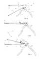
- FIG. 1shows a plan view of a surgical instrument according to the invention
- FIG. 2shows a plan view of the surgical instrument according to FIG. 1 in a further position of use
- FIG. 3shows an enlarged sectional view of part of the surgical instrument according to FIG. 2 ;
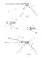
- FIG. 4shows a plan view of a further illustrative embodiment of a surgical instrument in an exploded illustration
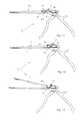
- FIG. 5shows a plan view of a further illustrative embodiment of a surgical instrument
- FIG. 6shows a plan view of the surgical instrument according to FIG. 5 in a further position of use
- FIG. 7shows a plan view of a further illustrative embodiment of a surgical instrument
- FIG. 8shows an enlarged bottom view of part of a slide from FIG. 7 ;
- FIG. 9shows an enlarged bottom view of part of the slide according to FIG. 7 in a further position of use
- FIG. 10shows a plan view of the surgical instrument according to FIG. 7 in a further position of use
- FIG. 11shows a plan view of a further illustrative embodiment of a surgical instrument
- FIG. 12shows a plan view of a further illustrative embodiment of a surgical instrument
- FIG. 13shows a plan view of the surgical instrument according to FIG. 12 in a further position of use
- FIG. 14shows a plan view of a further illustrative embodiment of a surgical instrument
- FIGS. 15 and 16show enlarged perspective views of a detail from FIG. 14 in different positions of a rocker lever
- FIG. 17shows a plan view of the surgical instrument according to FIG. 14 in a further position of use
- FIG. 18shows a plan view of a further illustrative embodiment of a surgical instrument during assembly
- FIGS. 19 and 20show two plan views of the surgical instrument according to FIG. 18 in different positions of use
- FIG. 21shows a plan view of a pushbutton, shown enlarged, with a protruding stepped pin.
- a surgical instrument P 1has a shank 1 , which is connected to a fixed handle part 2 .
- This fixed handle part 2is also connected via a pivot 3 to a movable handle part 4 , this movable handle part 4 being able to be swiveled about the pivot 3 .
- a slide 5is moved along the shank 1 .
- Guide elements 6 . 1 and 6 . 2which are provided on an underside 7 of the slide 5 , engage in longitudinal grooves 8 . 1 and 8 . 2 in the shank 1 , said guide elements 6 . 1 and 6 .
- the slide 5is connected to a pusher part 13 which is provided below a crosspiece 14 , which engages in a slot 15 (see FIG. 3 ) in the movable handle part 4 , with guide elements 16 , which in turn are guided in undercut grooves 10 . 1 in a continuation of the longitudinal groove 8 . 2 .
- a locking mechanism 17is provided as described in DE 201 03 630 A1.
- This locking mechanism 17comprises a pin as limit stop 18 which, by actuation by means of a slide button 19 , can be pushed out of the longitudinal groove 8 . 2 counter to the force of a helical spring (not shown) located in a cavity 20 of a blind hole 21 . Between the slide button 19 and the limit stop 18 , there is a connecting pin 22 .
- the mode of operation of the present inventionis as follows:
- the guide elements 6 . 1 , 6 . 2 and 16are in engagement with the corresponding undercut grooves 10 , 10 . 1 and 10 . 2 , such that, when the movable handle part 4 is actuated, the slide 5 can be moved along the shank 1 , and a sample of tissue is removed, for example by means of a punch jaw 23 .
- the movable handle part 4can be opened still further about the pivot 3 , such that the guide elements 16 of the pusher part 13 are in the end also disengaged from the undercut grooves 10 . 1 . In this way, the pusher part 13 can also be detached from the fixed handle part 2 , the crosspiece 14 sliding out of the slot 15 .
- the fixed handle part 2can be provided, near the movable handle part 4 , with a limit stop 28 which ensures that the movable handle part 4 cannot be opened so far that the guide elements 16 are disengaged from the undercut grooves 10 . 1 .
- FIG. 4shows a further illustrative embodiment of a surgical instrument P 1 .
- the fixed handle part 2 and the movable handle part 4correspond to those according to FIGS. 1 and 2 , as also do the pivot 3 , the locking mechanism 17 , the crosspiece 14 and the slot 15 .
- the guide elements 6 . 1 and 6 . 2are likewise provided on the slide 5 . 1 , which in this case has no pivot, and in which instead the pusher part forms part of the overall slide 5 . 1 .
- shank 1 . 1is not integrally connected to the fixed handle part 2 , but is instead articulated thereon via a pivot 12 . 1 .
- the rear guide element 16is also absent, with the result that, after the locking mechanism 17 has been actuated and the shank 1 . 1 folded down, the slide 5 . 1 comes completely free from the shank 1 . 1 and the fixed handle part 2 .
- the illustrative embodiment of a surgical instrument P 2 according to FIGS. 5 and 6differs from the above-described illustrative embodiments in terms of the design of the locking mechanism and the arrangement of the guide elements and longitudinal grooves.
- the guide element 6 . 1protrudes as before from the slide 5 . 2 and engages in the longitudinal groove 8 . 1 in the shank 1 . 2
- a guide element 6 . 3 in the proximal areaprotrudes from the shank 1 . 2 and cooperates with a longitudinal groove 8 . 3 in the slide 5 . 2 .
- the corresponding undercut grooves 10 . 3 in the longitudinal groove 8In this case, the corresponding undercut grooves 10 . 3 in the longitudinal groove 8 .
- the locking mechanism 17 . 1is located in front of the guide element 6 . 3 .
- This locking mechanism 17 . 1has a pull knob 29 , with which a limit stop designed as a pin 30 can be pulled from the inside width of the longitudinal groove 8 . 3 .
- the slide 5 . 2can be moved further to the left, such that the guide element 6 . 3 moves into an area of the longitudinal groove 8 . 3 that is no longer covered by the undercut groove 10 . 3 .
- the guide element 6 . 3frees the slide 5 . 2 , such that the latter can fold out, since the guide element 6 . 1 in the longitudinal groove 8 . 1 is also freed at the same time.
- a limit stopdesigned as a pushbutton 50 , which is arranged laterally on the slide 5 . 2 and in which a recess 31 is formed.
- the pushbutton 50When the pushbutton 50 is pressed counter to the force of a spring 32 , the recess 31 comes into line with the longitudinal groove 8 . 3 , such that the guide element 6 . 3 , as is shown in FIG. 9 , can travel into the recess 31 , with the result that it slides out of the undercut grooves 10 . 3 and the slide 5 . 2 is freed
- a rocker lever 33sits on the slide 5 . 2 and comprises, projecting down from it, a lug 34 which acts as a limit stop and which engages in the inside width of the longitudinal groove 8 . 3 in front of the guide element 6 . 3 .
- the rocker lever 33is actuated by pressing on the lever arm 35 counter to the force of a spring 36 , the lug 34 is removed from the inside width of the longitudinal groove 8 . 3 , such that the guide element 6 . 3 can reach an area in the longitudinal groove 8 . 3 in which it is freed.
- a rotary lever 37is located on the slide 5 .
- the rotary lever 37can be turned about a rotation axis 38 , said rotation axis 38 being situated behind the pivot 12 .
- the rotary lever 37engages with a front pressure arm 39 over the slide 5 , such that the slide 5 is held bearing on the shank 1 . This position is secured by a spring-mounted locking pin 40 in the slide 5 .
- a rocker lever 41is situated in the fixed handle part 2 and can act as a limit stop for the movable handle part 4 .
- This rocker lever 41can turn about an axis 42 , such that its upper edge 43 either engages behind the movable handle part 4 or frees it.
- the edge 43is recessed in the fixed handle part 2 and, as is shown in FIG. 14 , engages behind the upper part of the movable handle part 4 .
- the guide element 6 . 2cannot escape from the undercut grooves 10 . 2 and is instead trapped in these grooves 10 . 2 , such that the slide 5 cannot be separated from the shank 1 .
- a third positionis also conceivable in which the movable handle part 4 can be opened still further, such that the guide element 16 can be removed from the undercut grooves 10 . 2 and the slide 5 is completely freed.
- FIGS. 18 to 20A particularly simple illustrative embodiment of a surgical instrument P 7 is shown in FIGS. 18 to 20 .
- the pivot 3 . 1is designed in a particularly simple way, such that protection is requested for this especially.
- this bore 44is also adjoined by an oblong hole 45 .
- This embodimentis assigned a special pushbutton 46 , from which there protrudes a stepped pin 47 (shown enlarged in FIG. 21 ).
- the pushbutton 46 with its pin 47is subjected to the pressure of a suitably arranged helical spring.
- the pin parts 48 . 1 and 48 . 2 of greater diameterare situated in the bores 44 of the movable handle part 4 . 1 and of the fixed handle part 2 .
- the pin part 48 . 3 of smaller diameter, corresponding to the width of the oblong hole 45is brought into the area of the latter, the movable handle part 4 . 1 , as shown in FIG. 18 , can be pulled downward.
- the crosspiece 14slips out of the slot 15 and the slide 5 is freed, such that it can be detached from the shank 1 .
- the fixed handle part 2also comprises a leaf spring 49 , which counteracts a rotation movement of the movable handle part 4 .
- the manufacturerdoes not have to provide a corresponding spreader element between the fixed handle part 2 and the movable handle part 4 .
Landscapes
- Health & Medical Sciences (AREA)
- Surgery (AREA)
- Life Sciences & Earth Sciences (AREA)
- Biomedical Technology (AREA)
- Medical Informatics (AREA)
- Orthopedic Medicine & Surgery (AREA)
- Oral & Maxillofacial Surgery (AREA)
- Engineering & Computer Science (AREA)
- Dentistry (AREA)
- Heart & Thoracic Surgery (AREA)
- Nuclear Medicine, Radiotherapy & Molecular Imaging (AREA)
- Molecular Biology (AREA)
- Animal Behavior & Ethology (AREA)
- General Health & Medical Sciences (AREA)
- Public Health (AREA)
- Veterinary Medicine (AREA)
- Surgical Instruments (AREA)
- Dental Tools And Instruments Or Auxiliary Dental Instruments (AREA)
Abstract
Description
- 1 shank
- 2 fixed handle part
- 3 pivot
- 4 movable handle part
- 5 slide
- 6 guide element
- 7 underside
- 8 longitudinal groove
- 9 rail
- 10 undercut groove
- 11 partial area
- 12 pivot
- 13 pusher part
- 14 crosspiece
- 15 slot
- 16 guide element
- 17 locking mechanism
- 18 limit stop
- 19 slide button
- 20 cavity
- 21 blind hole
- 22 connecting pin
- 23 punch jaw
- 24 space
- 25 rear edge
- 26 control edge
- 27 transverse pin
- 28 limit stop
- 29 pull knob
- 30 pin
- 31 recess
- 32 spring
- 33 rocker lever
- 34 lug
- 35 lever arm
- 36 spring
- 37 rotary lever
- 38 rotation axis
- 39 pressure arm
- 40 locking pin
- 41 rocker lever
- 42 axis
- 43 edge
- 44 bore
- 45 oblong hole
- 46 pushbutton
- 47 pin
- 48 pin parts
- 49 leaf spring
- 50 pushbutton
- P surgical instrument
Claims (25)
Applications Claiming Priority (4)
| Application Number | Priority Date | Filing Date | Title |
|---|---|---|---|
| DE102006012754 | 2006-03-17 | ||
| DE102006012754.4ADE102006012754B4 (en) | 2006-03-17 | 2006-03-17 | Surgical instrument |
| DE102006012754.4 | 2006-03-17 | ||
| PCT/EP2007/001784WO2007107227A2 (en) | 2006-03-17 | 2007-03-02 | Surgical instrument |
Publications (2)
| Publication Number | Publication Date |
|---|---|
| US20090209998A1 US20090209998A1 (en) | 2009-08-20 |
| US8048106B2true US8048106B2 (en) | 2011-11-01 |
Family
ID=38137478
Family Applications (1)
| Application Number | Title | Priority Date | Filing Date |
|---|---|---|---|
| US12/225,191Expired - Fee RelatedUS8048106B2 (en) | 2006-03-17 | 2007-03-02 | Surgical instrument |
Country Status (4)
| Country | Link |
|---|---|
| US (1) | US8048106B2 (en) |
| EP (2) | EP2578171B1 (en) |
| DE (1) | DE102006012754B4 (en) |
| WO (1) | WO2007107227A2 (en) |
Cited By (7)
| Publication number | Priority date | Publication date | Assignee | Title |
|---|---|---|---|---|
| US20110172647A1 (en)* | 2009-11-30 | 2011-07-14 | Raimund Wenzler Gmbh | Surgical instrument |
| US20130041378A1 (en)* | 2011-07-28 | 2013-02-14 | David M. Funnell | Rongeur with vented t-slide and/or increased strength |
| US20140236204A1 (en)* | 2013-02-18 | 2014-08-21 | LT technologies GmbH & Co. KG | Surgical instrument |
| US20160135817A1 (en)* | 2014-11-19 | 2016-05-19 | Specialty Surgical Instrumentation, Inc. | Adjustable Rongeur |
| US9358027B2 (en) | 2012-08-22 | 2016-06-07 | Wexler Surgical, Inc. | Thoracoscopic instrument |
| US10780750B2 (en) | 2013-12-05 | 2020-09-22 | Continental Automotive France | Method for determining a wheel tire ground print |
| US20230091552A1 (en)* | 2021-09-17 | 2023-03-23 | Koros U.S.A., Inc. | Rongeurs and other medical instruments |
Families Citing this family (37)
| Publication number | Priority date | Publication date | Assignee | Title |
|---|---|---|---|---|
| US8257371B2 (en) | 2007-03-15 | 2012-09-04 | Suturenetics, Inc. | Limited access suturing devices, system, and methods |
| US8911456B2 (en) | 2007-07-03 | 2014-12-16 | Ceterix Orthopaedics, Inc. | Methods and devices for preventing tissue bridging while suturing |
| US10441273B2 (en) | 2007-07-03 | 2019-10-15 | Ceterix Orthopaedics, Inc. | Pre-tied surgical knots for use with suture passers |
| US8663253B2 (en) | 2007-07-03 | 2014-03-04 | Ceterix Orthopaedics, Inc. | Methods of meniscus repair |
| US9314234B2 (en) | 2007-07-03 | 2016-04-19 | Ceterix Orthopaedics, Inc. | Pre-tied surgical knots for use with suture passers |
| US9211119B2 (en) | 2007-07-03 | 2015-12-15 | Ceterix Orthopaedics, Inc. | Suture passers and methods of passing suture |
| US9861354B2 (en) | 2011-05-06 | 2018-01-09 | Ceterix Orthopaedics, Inc. | Meniscus repair |
| US8500809B2 (en) | 2011-01-10 | 2013-08-06 | Ceterix Orthopaedics, Inc. | Implant and method for repair of the anterior cruciate ligament |
| US8821518B2 (en) | 2007-11-05 | 2014-09-02 | Ceterix Orthopaedics, Inc. | Suture passing instrument and method |
| US8702731B2 (en) | 2007-07-03 | 2014-04-22 | Ceterix Orthopaedics, Inc. | Suturing and repairing tissue using in vivo suture loading |
| US20090012538A1 (en)* | 2007-07-03 | 2009-01-08 | Justin Saliman | Methods and devices for continuous suture passing |
| US8465505B2 (en) | 2011-05-06 | 2013-06-18 | Ceterix Orthopaedics, Inc. | Suture passer devices and methods |
| US9848868B2 (en) | 2011-01-10 | 2017-12-26 | Ceterix Orthopaedics, Inc. | Suture methods for forming locking loops stitches |
| JP5719374B2 (en) | 2009-11-09 | 2015-05-20 | セテリックス オーソピーディクス インコーポレイテッド | Device, system, and method for repairing a meniscus |
| US9011454B2 (en) | 2009-11-09 | 2015-04-21 | Ceterix Orthopaedics, Inc. | Suture passer with radiused upper jaw |
| US11744575B2 (en) | 2009-11-09 | 2023-09-05 | Ceterix Orthopaedics, Inc. | Suture passer devices and methods |
| US8398657B2 (en)* | 2009-11-19 | 2013-03-19 | Lsi Solutions, Inc. | Multi-fire suturing instrument with proximal ferrule release feature |
| DE102010013296A1 (en)* | 2010-03-29 | 2011-09-29 | Glaser Gmbh | Surgical instrument |
| US9913638B2 (en) | 2011-01-10 | 2018-03-13 | Ceterix Orthopaedics, Inc. | Transosteal anchoring methods for tissue repair |
| CN103796597A (en) | 2011-06-08 | 2014-05-14 | 苏图勒内蒂克斯股份有限公司 | Offset jaw suturing device, system, and methods |
| DE102011109721B4 (en)* | 2011-08-06 | 2021-10-07 | Richard Wolf Gmbh | Surgical instrumet |
| US10524778B2 (en) | 2011-09-28 | 2020-01-07 | Ceterix Orthopaedics | Suture passers adapted for use in constrained regions |
| US9492162B2 (en) | 2013-12-16 | 2016-11-15 | Ceterix Orthopaedics, Inc. | Automatically reloading suture passer devices and methods |
| US9867626B2 (en)* | 2012-08-03 | 2018-01-16 | Boss Instruments Ltd., Inc. | Push button Rongeur |
| WO2014085870A1 (en) | 2012-12-08 | 2014-06-12 | Kevin Seex | Surgical tool |
| US9247935B2 (en) | 2013-09-23 | 2016-02-02 | Ceterix Orthopaedics, Inc. | Arthroscopic knot pusher and suture cutter |
| US11033182B2 (en) | 2014-02-21 | 2021-06-15 | 3Dintegrated Aps | Set comprising a surgical instrument |
| CN204951031U (en) | 2014-04-08 | 2016-01-13 | 赛特里克斯整形公司 | Ware device is worn to draw by suture |
| CN104367371A (en)* | 2014-09-30 | 2015-02-25 | 厦门大博颖精医疗器械有限公司 | Detachable rongeur |
| DE102015100945A1 (en)* | 2015-01-22 | 2016-07-28 | Dannoritzer Medizintechnik Gmbh & Co. Kg | Handle device |
| US10226245B2 (en) | 2015-07-21 | 2019-03-12 | Ceterix Orthopaedics, Inc. | Automatically reloading suture passer devices that prevent entanglement |
| CN108024806B (en) | 2015-07-21 | 2022-07-01 | 3D集成公司 | Cannula assembly kit, trocar assembly kit, sleeve assembly, minimally invasive surgical system and method thereof |
| US11020144B2 (en) | 2015-07-21 | 2021-06-01 | 3Dintegrated Aps | Minimally invasive surgery system |
| US10405853B2 (en) | 2015-10-02 | 2019-09-10 | Ceterix Orthpaedics, Inc. | Knot tying accessory |
| DK178899B1 (en) | 2015-10-09 | 2017-05-08 | 3Dintegrated Aps | A depiction system |
| DE102017116935A1 (en) | 2017-07-26 | 2019-01-31 | Karl Storz Se & Co. Kg | Surgical instrument |
| DE102023103519A1 (en)* | 2023-02-14 | 2024-08-14 | BAK Kohler Medical KG | Surgical instrument |
Citations (20)
| Publication number | Priority date | Publication date | Assignee | Title |
|---|---|---|---|---|
| US5451227A (en)* | 1989-04-24 | 1995-09-19 | Michaelson; Gary K. | Thin foot plate multi bite rongeur |
| US5569258A (en)* | 1995-06-22 | 1996-10-29 | Logan Instruments, Inc. | Laminectomy rongeurs |
| US5584844A (en)* | 1993-05-19 | 1996-12-17 | Aesculap Ag | Instrument for surgical purposes |
| US5961531A (en)* | 1998-05-13 | 1999-10-05 | Kmedic, Inc. | Convertible rongeur |
| US6126674A (en)* | 1997-11-03 | 2000-10-03 | Mediplus Instruments Gmbh U. Co. Kg | Surgical sliding shaft instrument |
| US6214010B1 (en)* | 1999-11-04 | 2001-04-10 | Thompson Surgical Instruments, Inc. | Rongeur surgical instrument |
| US20020147460A1 (en)* | 1999-07-01 | 2002-10-10 | Uwe Bacher | Medical, especially surgical, instrument |
| US20020151931A1 (en)* | 2000-12-08 | 2002-10-17 | Thomas Tontarra | Surgical instrument |
| US6520979B1 (en)* | 1998-04-29 | 2003-02-18 | Thierry Loubens | Linking device for surgical instrument |
| US6547805B1 (en)* | 1998-07-03 | 2003-04-15 | Soprane Sa | Surgical instrument and connector for permitting independent assembly and disassembly of a mobile cutting element and a mobile grip from a fixed body of the instrument |
| US20030088268A1 (en)* | 1999-12-17 | 2003-05-08 | Harald Weinmann | Surgical sliding shaft instrument |
| US6685710B2 (en)* | 2001-10-10 | 2004-02-03 | Codman & Shurtleff, Inc. | Rongeur with detachable crossbar |
| US6723103B2 (en)* | 2002-09-06 | 2004-04-20 | Elizabeth Ann Edwards | Rongeur and rongeur cleaning method |
| US6991633B2 (en)* | 2001-10-10 | 2006-01-31 | Codman & Shurtleff, Inc. | Rongeur with detachable crossbar |
| US20060111737A1 (en)* | 2004-11-19 | 2006-05-25 | Jorg Wenzler | Surgical punching instrument |
| US7052505B2 (en)* | 2001-03-01 | 2006-05-30 | Heinrich Widmann | Surgical instrument |
| US7377933B2 (en)* | 2004-11-29 | 2008-05-27 | S.U.A. Martin Gmbh & Co. Kg | Surgical instrument |
| US7611517B2 (en)* | 2004-02-27 | 2009-11-03 | Warsaw Orthopedic, Inc. | Rod reducer |
| US7691107B2 (en)* | 2005-09-30 | 2010-04-06 | Schneiter James A | Rongeur |
| US7708757B2 (en)* | 2004-08-24 | 2010-05-04 | Karl Storz Gmbh & Co. Kg | Medical forceps |
Family Cites Families (4)
| Publication number | Priority date | Publication date | Assignee | Title |
|---|---|---|---|---|
| DE19513572C2 (en)* | 1995-04-19 | 1998-10-15 | Rudolf Gmbh Medizintechnik | Surgical instrument |
| DE19702079A1 (en) | 1997-01-22 | 1998-07-23 | Aesculap Ag & Co Kg | Surgical instrument with two arms and swivel bearing |
| US7059509B2 (en) | 2002-05-28 | 2006-06-13 | Phillip Clay Brown | Surgical stapling device |
| DE10323958B4 (en) | 2003-05-27 | 2006-01-19 | S. U. A. Martin Gmbh & Co Kg | Surgical instrument |
- 2006
- 2006-03-17DEDE102006012754.4Apatent/DE102006012754B4/enactiveActive
- 2007
- 2007-03-02EPEP20120198512patent/EP2578171B1/enactiveActive
- 2007-03-02EPEP07703575.6Apatent/EP1996091B1/enactiveActive
- 2007-03-02USUS12/225,191patent/US8048106B2/ennot_activeExpired - Fee Related
- 2007-03-02WOPCT/EP2007/001784patent/WO2007107227A2/enactiveApplication Filing
Patent Citations (21)
| Publication number | Priority date | Publication date | Assignee | Title |
|---|---|---|---|---|
| US5451227A (en)* | 1989-04-24 | 1995-09-19 | Michaelson; Gary K. | Thin foot plate multi bite rongeur |
| US5584844A (en)* | 1993-05-19 | 1996-12-17 | Aesculap Ag | Instrument for surgical purposes |
| US5569258A (en)* | 1995-06-22 | 1996-10-29 | Logan Instruments, Inc. | Laminectomy rongeurs |
| US6126674A (en)* | 1997-11-03 | 2000-10-03 | Mediplus Instruments Gmbh U. Co. Kg | Surgical sliding shaft instrument |
| US6520979B1 (en)* | 1998-04-29 | 2003-02-18 | Thierry Loubens | Linking device for surgical instrument |
| US5961531A (en)* | 1998-05-13 | 1999-10-05 | Kmedic, Inc. | Convertible rongeur |
| US6547805B1 (en)* | 1998-07-03 | 2003-04-15 | Soprane Sa | Surgical instrument and connector for permitting independent assembly and disassembly of a mobile cutting element and a mobile grip from a fixed body of the instrument |
| US20020147460A1 (en)* | 1999-07-01 | 2002-10-10 | Uwe Bacher | Medical, especially surgical, instrument |
| US6214010B1 (en)* | 1999-11-04 | 2001-04-10 | Thompson Surgical Instruments, Inc. | Rongeur surgical instrument |
| US20030088268A1 (en)* | 1999-12-17 | 2003-05-08 | Harald Weinmann | Surgical sliding shaft instrument |
| US20020151931A1 (en)* | 2000-12-08 | 2002-10-17 | Thomas Tontarra | Surgical instrument |
| US6802852B2 (en)* | 2000-12-08 | 2004-10-12 | Tontarra Medizintechnik Gmbh | Surgical instrument |
| US7052505B2 (en)* | 2001-03-01 | 2006-05-30 | Heinrich Widmann | Surgical instrument |
| US6685710B2 (en)* | 2001-10-10 | 2004-02-03 | Codman & Shurtleff, Inc. | Rongeur with detachable crossbar |
| US6991633B2 (en)* | 2001-10-10 | 2006-01-31 | Codman & Shurtleff, Inc. | Rongeur with detachable crossbar |
| US6723103B2 (en)* | 2002-09-06 | 2004-04-20 | Elizabeth Ann Edwards | Rongeur and rongeur cleaning method |
| US7611517B2 (en)* | 2004-02-27 | 2009-11-03 | Warsaw Orthopedic, Inc. | Rod reducer |
| US7708757B2 (en)* | 2004-08-24 | 2010-05-04 | Karl Storz Gmbh & Co. Kg | Medical forceps |
| US20060111737A1 (en)* | 2004-11-19 | 2006-05-25 | Jorg Wenzler | Surgical punching instrument |
| US7377933B2 (en)* | 2004-11-29 | 2008-05-27 | S.U.A. Martin Gmbh & Co. Kg | Surgical instrument |
| US7691107B2 (en)* | 2005-09-30 | 2010-04-06 | Schneiter James A | Rongeur |
Non-Patent Citations (1)
| Title |
|---|
| PCT International Search Report mailed on Oct. 17, 2007 for the corresponding International patent application No. PCT/EP2007/001784 (English translation enclosed).* |
Cited By (9)
| Publication number | Priority date | Publication date | Assignee | Title |
|---|---|---|---|---|
| US20110172647A1 (en)* | 2009-11-30 | 2011-07-14 | Raimund Wenzler Gmbh | Surgical instrument |
| US20130041378A1 (en)* | 2011-07-28 | 2013-02-14 | David M. Funnell | Rongeur with vented t-slide and/or increased strength |
| US9089345B2 (en)* | 2011-07-28 | 2015-07-28 | David M. Funnell | Rongeur with vented T-slide and/or increased strength |
| US9358027B2 (en) | 2012-08-22 | 2016-06-07 | Wexler Surgical, Inc. | Thoracoscopic instrument |
| US20140236204A1 (en)* | 2013-02-18 | 2014-08-21 | LT technologies GmbH & Co. KG | Surgical instrument |
| US10780750B2 (en) | 2013-12-05 | 2020-09-22 | Continental Automotive France | Method for determining a wheel tire ground print |
| US20160135817A1 (en)* | 2014-11-19 | 2016-05-19 | Specialty Surgical Instrumentation, Inc. | Adjustable Rongeur |
| US9931127B2 (en)* | 2014-11-19 | 2018-04-03 | Specialty Surgical Instrumentation, Inc. | Adjustable rongeur |
| US20230091552A1 (en)* | 2021-09-17 | 2023-03-23 | Koros U.S.A., Inc. | Rongeurs and other medical instruments |
Also Published As
| Publication number | Publication date |
|---|---|
| EP2578171A1 (en) | 2013-04-10 |
| US20090209998A1 (en) | 2009-08-20 |
| WO2007107227A2 (en) | 2007-09-27 |
| WO2007107227A3 (en) | 2007-12-21 |
| EP2578171B1 (en) | 2015-05-06 |
| EP1996091B1 (en) | 2019-05-08 |
| DE102006012754A1 (en) | 2007-09-20 |
| DE102006012754B4 (en) | 2020-07-30 |
| EP1996091A2 (en) | 2008-12-03 |
Similar Documents
| Publication | Publication Date | Title |
|---|---|---|
| US8048106B2 (en) | Surgical instrument | |
| US6699254B1 (en) | Surgical instrument | |
| EP2326262B1 (en) | Laminectomy forceps | |
| RU2506903C2 (en) | Surgical instrument, chiefly electrosurgical instrument | |
| EP2066239B1 (en) | Multifunctional biopsy instrument | |
| US5925050A (en) | Self-clearing bone biting instrument | |
| US5527339A (en) | Surgical instrument | |
| US5290309A (en) | Surgical instrument | |
| US8568442B2 (en) | Medical gripping and/or cutting instrument | |
| JPH05184588A (en) | Surgical suction clamp | |
| US20040073232A1 (en) | Surgical instrument | |
| EP1463455B1 (en) | Surgical tool | |
| CN106037847B (en) | Single-hand adjustable anastomosis mechanism of endoscope anastomat | |
| US20060189995A1 (en) | Rongeur that disassembles for cleaning | |
| US5439461A (en) | Grip for a surgical instrument | |
| US11771490B2 (en) | Blade cartridge for a surgical instrument | |
| US20060047304A1 (en) | Medical forceps | |
| JP2010046114A (en) | Surgical treatment instrument | |
| RU2846794C2 (en) | Knife cartridge for surgical instrument | |
| ITMC20080082A1 (en) | LAMINECTOMY FORCEPS. | |
| ITMC20080081A1 (en) | LAMINECTOMY FORCEPS. | |
| WO2008068741A2 (en) | Disposable medical instrument | |
| HK1180275A1 (en) | Folding knife with opening mechanism | |
| HK1180275B (en) | Folding knife with opening mechanism |
Legal Events
| Date | Code | Title | Description |
|---|---|---|---|
| ZAAA | Notice of allowance and fees due | Free format text:ORIGINAL CODE: NOA | |
| ZAAB | Notice of allowance mailed | Free format text:ORIGINAL CODE: MN/=. | |
| STCF | Information on status: patent grant | Free format text:PATENTED CASE | |
| FEPP | Fee payment procedure | Free format text:PAT HOLDER NO LONGER CLAIMS SMALL ENTITY STATUS, ENTITY STATUS SET TO UNDISCOUNTED (ORIGINAL EVENT CODE: STOL); ENTITY STATUS OF PATENT OWNER: LARGE ENTITY | |
| REFU | Refund | Free format text:REFUND - SURCHARGE, PETITION TO ACCEPT PYMT AFTER EXP, UNINTENTIONAL (ORIGINAL EVENT CODE: R2551); ENTITY STATUS OF PATENT OWNER: LARGE ENTITY | |
| AS | Assignment | Owner name:KARL STORZ GMBH & CO. KG, GERMANY Free format text:ASSIGNMENT OF ASSIGNORS INTEREST;ASSIGNOR:WIDMANN, HEINRICH;REEL/FRAME:035127/0841 Effective date:20150303 | |
| FPAY | Fee payment | Year of fee payment:4 | |
| AS | Assignment | Owner name:KARL STORZ SE & CO. KG, GERMANY Free format text:CHANGE OF NAME;ASSIGNOR:KARL STORZ GMBH & CO. KG;REEL/FRAME:045373/0627 Effective date:20170911 | |
| MAFP | Maintenance fee payment | Free format text:PAYMENT OF MAINTENANCE FEE, 8TH YEAR, LARGE ENTITY (ORIGINAL EVENT CODE: M1552); ENTITY STATUS OF PATENT OWNER: LARGE ENTITY Year of fee payment:8 | |
| FEPP | Fee payment procedure | Free format text:MAINTENANCE FEE REMINDER MAILED (ORIGINAL EVENT CODE: REM.); ENTITY STATUS OF PATENT OWNER: LARGE ENTITY | |
| LAPS | Lapse for failure to pay maintenance fees | Free format text:PATENT EXPIRED FOR FAILURE TO PAY MAINTENANCE FEES (ORIGINAL EVENT CODE: EXP.); ENTITY STATUS OF PATENT OWNER: LARGE ENTITY | |
| STCH | Information on status: patent discontinuation | Free format text:PATENT EXPIRED DUE TO NONPAYMENT OF MAINTENANCE FEES UNDER 37 CFR 1.362 | |
| FP | Lapsed due to failure to pay maintenance fee | Effective date:20231101 |