US8047970B2 - Weight plate with detachable locking cartridge - Google Patents
Weight plate with detachable locking cartridgeDownload PDFInfo
- Publication number
- US8047970B2 US8047970B2US12/217,743US21774308AUS8047970B2US 8047970 B2US8047970 B2US 8047970B2US 21774308 AUS21774308 AUS 21774308AUS 8047970 B2US8047970 B2US 8047970B2
- Authority
- US
- United States
- Prior art keywords
- plate body
- locking
- cartridge
- weight
- weight plate
- Prior art date
- Legal status (The legal status is an assumption and is not a legal conclusion. Google has not performed a legal analysis and makes no representation as to the accuracy of the status listed.)
- Active, expires
Links
Images


Classifications
- A—HUMAN NECESSITIES
- A63—SPORTS; GAMES; AMUSEMENTS
- A63B—APPARATUS FOR PHYSICAL TRAINING, GYMNASTICS, SWIMMING, CLIMBING, OR FENCING; BALL GAMES; TRAINING EQUIPMENT
- A63B21/00—Exercising apparatus for developing or strengthening the muscles or joints of the body by working against a counterforce, with or without measuring devices
- A63B21/06—User-manipulated weights
- A63B21/062—User-manipulated weights including guide for vertical or non-vertical weights or array of weights to move against gravity forces
- A63B21/0626—User-manipulated weights including guide for vertical or non-vertical weights or array of weights to move against gravity forces with substantially vertical guiding means
- A63B21/0628—User-manipulated weights including guide for vertical or non-vertical weights or array of weights to move against gravity forces with substantially vertical guiding means for vertical array of weights
- A63B21/063—Weight selecting means
- A—HUMAN NECESSITIES
- A63—SPORTS; GAMES; AMUSEMENTS
- A63B—APPARATUS FOR PHYSICAL TRAINING, GYMNASTICS, SWIMMING, CLIMBING, OR FENCING; BALL GAMES; TRAINING EQUIPMENT
- A63B2225/00—Miscellaneous features of sport apparatus, devices or equipment
- A63B2225/30—Maintenance
Definitions
- This inventionrelates to a weight plate of the kind common to physical fitness weight lifting equipment to be coupled to a lifting element (e.g., a center post) of such equipment and lifted during a body building exercise.
- the weight plateincludes a detachable locking cartridge having a manually-controlled locking pin that slides reciprocally through the plate body so that the weight plate can be either positively attached to or separated from the lifting element.
- My co-pending patent application Ser. No. 11/349,101 filed Feb. 8, 2006discloses a weight plate that is associated with weight lifting equipment by which the weight plate or a stack of weight plates can be lifted during a body building exercise.
- This weight plateincludes a plate body and a locking cartridge connected to the plate body.
- the displacement of a locking pin through the weight plate bodyis controlled by a manually-accessible toggle lever arm that is located within the locking cartridge and coupled to the locking pin.
- the toggle lever armWhen the toggle lever arm is rotated to an on or locked position, the locking pin is correspondingly caused to slide in a first direction through the plate body to engage a connection union mounted in an adjacent weight plate.
- the toggle lever armWhen the toggle lever arm is rotated to an off or unlocked position, the locking in is caused to slide in an opposite direction through the plate body to be disengaged from the connection union.
- the locking cartridgecan be attached to a conventional plate body so that the weight plate can be selectively and reliably attached to a lifting element of the weight lifting equipment so as to be lifted with a stack of similarly-attached weight plates during a body building exercise.
- a weight platethat is common to certain physical fitness weight lifting equipment in which one or a stack of weight plates are lifted during a body building exercise.
- the weight plateincludes a plate body having a central bore and a pair of side bores formed therethrough.
- the central bore through the plate bodyis sized to receive a lifting element (e.g., the center post) from the weight lifting equipment, and the side bores are sized to receive respective stabilizing guide bars from the equipment.
- a locking cartridgeis detachably connected to the plate body so that the weight plate can be releasably attached to the lifting element of the weight lifting equipment.
- the center postis tied to a cable to which a pulling force is applied to cause the lifting element and the weight plates carried thereby to be lifted during the body building exercise.
- the detachable locking cartridgeis mounted against one side of the plate body so as to lie entirely external to the plate body.
- the detachable locking cartridgeis removably received within an internal cavity formed in one side of the plate body.
- a pair of fastenersextend through the detachable locking cartridge by which the locking cartridge may be removably connected to the plate body.
- An anchor stud projecting from the locking cartridgeis received in an opposing stud hole formed in the plate body to prevent the locking cartridge from sliding over the plate body.
- the detachable locking cartridgecan be connected to a conventional plate body to enable the weight plate to be attached to the lifting element.
- the locking cartridgeincludes a housing and a manually-operated toggle lever switch arm that is adapted to rotate within the housing between on and off positions.
- a locking pinis slidable reciprocally through a locking channel of the locking cartridge and an axially-aligned guide channel of the plate body so as to be displaced relative to the center hole of the plate body.
- the locking pinis disposed in perpendicular alignment with the side of the plate body to which the locking cartridge is detachably connected.
- One end of the toggle lever switch armis manually accessible outside the housing of the locking cartridge to receive a rotational force applied by a user, and the opposite end of the switch arm is coupled to the locking pin so that a rotation of the switch arm results in a linear displacement of the locking pin relative to the center hole of the plate body.
- the locking pinwhen the toggle lever switch arm is rotated to the on position, the locking pin is correspondingly displaced in a first direction through the locking and guide channels so as to slide into the center hole in the plate body at which to be attached to the lifting element of the weight lifting apparatus.
- the switch armWhen the switch arm is rotated to the off position, the locking pin is displaced in an opposite direction so as to slide out of the center hole to be detached from the lifting element.
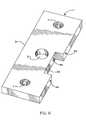
- FIG. 1shows an external locking cartridge according to a first preferred embodiment of this invention detachably connected to one side of a weight plate that is common to certain physical fitness weight lifting equipment;
- FIG. 2shows a rotatable toggle lever switch arm of the external locking cartridge of FIG. 1 coupled to a locking pin that is slidable through the plate body depending upon a rotation of the switch arm;
- FIG. 3shows the toggle lever switch arm rotated to an off position for causing the locking pin of the detachable locking cartridge to slide through the weight plate body and out of a central bore formed therein;
- FIG. 4shows the toggle lever switch arm rotated to an on position for causing the locking pin of the detachable locking cartridge to slide through the weight plate body and into the central bore thereof;
- FIG. 5shows a locking cartridge according to an alternate preferred embodiment detachably connected to a weight plate at an internal locking cavity formed therein.
- FIG. 6shows one embodiment of the weight plate of FIG. 5 .
- the modified weight plate 1that can be used in combination with or in place of the weight plate described in my co-pending patent application Ser. No. 11/349,101.
- the modified weight plate 1 herein disclosedincludes a rectangular plate body 3 with a (e.g., 11 ⁇ 2 inch diameter) central bore 5 running therethrough and a side bore 7 located adjacent each side of the central bore 5 .
- the weight plate 1is typically cast from iron, steel, urethane, rubber, plastic or a suitable composite material and is preferably about ten inches long, four inches wide and one inch thick. It is contemplated that the weight plate 1 will be manufactured in five- and 10-pound units.
- the aforementioned materials and dimensionsare for the purpose of example only and should not be regarded as limitations of this invention.
- the central bore 5 through the body 3 of weight plate 1is sized to receive therethrough a lifting element (e.g., a center post designated 34 in FIGS. 3 and 4 ) that is common to some weight lifting equipment by which a stack of weight plates carried by the lifting element is raised.
- the side bores 7 through plate body 3are sized to receive respective guide bars (not shown) to stabilize and prevent rotation of the stack of weight plates positioned one above the other and carried by the lifting element during body building exercises. Because the receipt of the central and side bores 5 and 7 of weight plate 1 by a lifting element and guide bars as just described is known to those in the body building art, no further description thereof will be presented.
- an external locking cartridge 10Lying entirely outside and lying flush against one side (e.g., the bottom) 9 of the plate body 3 is an external locking cartridge 10 .
- Fasteners (e.g., facial screws) 8extend through opposite ends of a housing 11 of the external locking cartridge 10 whereby the cartridge is detachably connected to the side 9 of the plate body 3 .
- an independent external locking cartridge 10can be connected to a conventional weight plate commonly used during body building exercises to obtain the benefits of this invention.
- An anchor stud 12projects downwardly from approximately the middle of the housing 11 of locking cartridge 10 for receipt by an opposing locating hole that is formed in the side 9 of the plate body 3 .
- the anchor stud 12By virtue of the anchor stud 12 , the external locking cartridge 10 will be automatically positioned against side 9 to facilitate the reciprocal sliding displacement of an internal (e.g., steel) locking pin 14 through each of the locking cartridge 10 and the weight plate body 3 for a purpose that will soon be described. Moreover, the anchor stud 12 prevents the locking cartridge 10 from shifting along the side 9 to which it is connected.
- an internal (e.g., steel) locking pin 14through each of the locking cartridge 10 and the weight plate body 3 for a purpose that will soon be described.
- the anchor stud 12prevents the locking cartridge 10 from shifting along the side 9 to which it is connected.
- the internal locking pin 14is slidable relative to the central bore 5 in plate body 3 so as to be displaced through a locking channel 15 in the housing 11 of locking cartridge 10 and an axially-aligned guide channel 17 in plate body 3 .
- the locking pin 14is disposed in perpendicular alignment with the side 9 of plate body 3 so as to be capable of reciprocal movement through the axially-aligned locking channel 15 and guide channel 17 .
- the reciprocal displacement of the locking pin 14 through the locking and guide channels 15 and 17is selectively controlled by a manually-accessible switch control knob 16 that is manipulated (i.e., rotated) back and forth (in the direction indicated by the reference arrows of FIG.
- the switch control knob 16is coupled to the locking pin 14 by means of a rotatable (e.g., steel) toggle lever switch arm 20 located within housing 11 so that a rotational force applied to the control knob 16 is converted to a linear displacement of the locking pin 14 relative to the central bore 5 of plate body 3 .
- a rotatable (e.g., steel) toggle lever switch arm 20located within housing 11 so that a rotational force applied to the control knob 16 is converted to a linear displacement of the locking pin 14 relative to the central bore 5 of plate body 3 .
- the rotatable toggle lever switch arm 20 inside locking cartridge housing 11includes upper and lower arm members 22 and 24 that are aligned with one another to make an angle of approximately 90 degrees.
- One end of the upper arm member 22 of toggle lever switch arm 20extends through the guide slot 18 in the locking cartridge 10 to be attached to the manually-accessible switch control knob 16 .
- One end of the lower arm member 24 of switch arm 20includes a relatively wide switch head 26 that is positioned in and captured by a bore 27 that is formed near the top of the locking pin 14 , whereby a rotation of the switch control knob 16 results in a linear displacement of the locking pin 14 relative to the central bore 5 of plate body 3 .
- a swage pin 30runs laterally through the housing 11 of locking cartridge 10 and the elbow 28 to establish a pivot axis around which the toggle lever switch arm 20 will rotate in response to a rotational force applied by a user to the control knob 16 .
- the switch control knob 16can be manually manipulated (i.e., rotated) between an unlocked position (of FIG. 3 ) and a locked position (of FIG. 4 ).
- the upper arm member 22 of toggle lever switch arm 20is correspondingly rotated through the guide slot 18 at the top of the locking cartridge housing 11 .
- the lower arm member 24which is coupled to the internal locking pin 14 by receipt of switch head 26 at bore 27 rotates with the upper arm member 22 . That is, the switch arm 20 will rotate within the housing 11 of locking cartridge 10 around the swage pin 30 running through elbow 28 as the control knob 16 is manipulated between the aforementioned locked and unlocked positions.
- the locking pin 14is pulled in a first direction by the toggle lever switch arm 20 outwardly from the central bore 5 of plate body 3 and into the locking channel 15 of locking cartridge 10 .
- the weight plate 1is now easily added to or separated from a stack of weight plates that are held together by a lifting element (e.g., the center post represented by reference numeral 34 in FIGS. 3 and 4 ) that is removably received through the central bore 5 .
- a lifting elemente.g., the center post represented by reference numeral 34 in FIGS. 3 and 4
- the userwill be able to selectively control the total number of weight plates that are stacked together and carried by the lifting element 34 by adding or removing one or more weight plates to or from the stack to be lifted.
- the switch control knob 16is rotated to the locked position of FIG. 4 .
- the toggle lever switch arm 20is correspondingly rotated around swage pin 30 , whereby the switch head 26 that is coupled to the locking pin 14 at bore 27 thereof applies a pushing force against the locking pin.
- the locking pin 14is thusly caused to slide in an opposite direction through each of the axially-aligned locking channel 15 of locking cartridge housing 11 and the guide channel 17 of the plate body 3 so as to pass through the central bore 5 of plate body 3 at which to engage the lifting element 34 .
- a (e.g., coil) spring 32is connected to the lower arm member 22 of the toggle lever switch arm 20 , and an opposite end of spring 32 is connected to the housing 11 of the locking cartridge 10 .
- the spring 32urges the switch arm 20 to either one of the unlocked or locked positions along the guide slot 18 so as to avoid an indefinite, intermediate position therebetween.
- toggle lever switch arm 20that rotates within the housing 11 of the external locking cartridge 10 performs the function of a mechanical switch. That is to say, the switch control knob 16 is rotated between the unlocked (off) and locked (on) positions of FIGS. 3 and 4 so that the internal locking pin 14 is either withdrawn from or pushed through the central bore 5 of plate body 3 so as to be detached from or connected to the weight plate lifting element 34 within the central bore 5 .
- the external locking cartridge 10 of FIGS. 1-4is shown lying entirely outside and flush against one side 9 of the weight plate body 3 .
- a locking cartridge 10 - 1is removably connected to the body 3 - 1 of a modified weight plate 1 - 1 at an internal locking cavity 40 that is recessed within the plate body 3 - 1 (best shown in FIG. 6 ).
- the body 11 - 1 of locking cartridge 10 - 1has a stabilizer extension 42 projecting therefrom and sized for receipt within the locking cavity 40 to provide enhanced stability during use and prevent the locking cartridge 10 - 1 from shifting relative to the weight plate body 3 - 1 .
- the locking cartridge 10 - 1 of FIGS. 5 and 6include fasteners 8 - 1 which extend through outer ends of the housing 11 - 1 thereof for receipt by opposing holes 44 in the plate body 3 - 1 .
- an anchor stud 12 - 1projects from the stabilizer extension 42 for receipt within an opposing stud hole 46 located at the locking cavity 40 of plate body 3 - 1 .
- a switch control knob 16 - 1is rotated (in the direction of the reference arrows of FIG.
- the weight plate 1 - 1can advantageously be added to or separated from a stack of weight plates by simply rotating the switch control knob 16 - 1 to either one of a locked (on) or unlocked (off) position.
Landscapes
- Health & Medical Sciences (AREA)
- Life Sciences & Earth Sciences (AREA)
- Biophysics (AREA)
- Orthopedic Medicine & Surgery (AREA)
- General Health & Medical Sciences (AREA)
- Physical Education & Sports Medicine (AREA)
- Switch Cases, Indication, And Locking (AREA)
Abstract
Description
Claims (12)
Priority Applications (1)
| Application Number | Priority Date | Filing Date | Title |
|---|---|---|---|
| US12/217,743US8047970B2 (en) | 2008-07-09 | 2008-07-09 | Weight plate with detachable locking cartridge |
Applications Claiming Priority (1)
| Application Number | Priority Date | Filing Date | Title |
|---|---|---|---|
| US12/217,743US8047970B2 (en) | 2008-07-09 | 2008-07-09 | Weight plate with detachable locking cartridge |
Publications (2)
| Publication Number | Publication Date |
|---|---|
| US20100009819A1 US20100009819A1 (en) | 2010-01-14 |
| US8047970B2true US8047970B2 (en) | 2011-11-01 |
Family
ID=41505671
Family Applications (1)
| Application Number | Title | Priority Date | Filing Date |
|---|---|---|---|
| US12/217,743Active2029-07-16US8047970B2 (en) | 2008-07-09 | 2008-07-09 | Weight plate with detachable locking cartridge |
Country Status (1)
| Country | Link |
|---|---|
| US (1) | US8047970B2 (en) |
Cited By (32)
| Publication number | Priority date | Publication date | Assignee | Title |
|---|---|---|---|---|
| USD692073S1 (en)* | 2012-02-03 | 2013-10-22 | Mark Nalley | Locking cartridge for a weight plate |
| CN103768760A (en)* | 2014-02-24 | 2014-05-07 | 青岛英派斯健康科技有限公司 | Fitness machine |
| US9084913B2 (en) | 2013-03-08 | 2015-07-21 | Atlas Barbell, Llc | Locking mechanism |
| US9144703B2 (en) | 2012-10-05 | 2015-09-29 | Icon Health & Fitness, Inc. | Weight selector assemblies, exercise machines including such weight selector assemblies, and related methods |
| US9339681B1 (en)* | 2014-12-02 | 2016-05-17 | Core Health & Fitness, Llc | Weight plate with center post locking cartridge and locking fork |
| US9498668B2 (en) | 2014-03-10 | 2016-11-22 | Icon Health & Fitness, Inc. | Automated weight selector |
| US10188890B2 (en) | 2013-12-26 | 2019-01-29 | Icon Health & Fitness, Inc. | Magnetic resistance mechanism in a cable machine |
| US10252109B2 (en) | 2016-05-13 | 2019-04-09 | Icon Health & Fitness, Inc. | Weight platform treadmill |
| US10258828B2 (en) | 2015-01-16 | 2019-04-16 | Icon Health & Fitness, Inc. | Controls for an exercise device |
| US10272317B2 (en) | 2016-03-18 | 2019-04-30 | Icon Health & Fitness, Inc. | Lighted pace feature in a treadmill |
| US10279212B2 (en) | 2013-03-14 | 2019-05-07 | Icon Health & Fitness, Inc. | Strength training apparatus with flywheel and related methods |
| US10293211B2 (en) | 2016-03-18 | 2019-05-21 | Icon Health & Fitness, Inc. | Coordinated weight selection |
| US10307637B2 (en) | 2017-02-13 | 2019-06-04 | Mark Nalley | Exercise machine having horizontally extending and selectively connected weight plates |
| US10343017B2 (en) | 2016-11-01 | 2019-07-09 | Icon Health & Fitness, Inc. | Distance sensor for console positioning |
| US10376736B2 (en) | 2016-10-12 | 2019-08-13 | Icon Health & Fitness, Inc. | Cooling an exercise device during a dive motor runway condition |
| US10426989B2 (en) | 2014-06-09 | 2019-10-01 | Icon Health & Fitness, Inc. | Cable system incorporated into a treadmill |
| US10433612B2 (en) | 2014-03-10 | 2019-10-08 | Icon Health & Fitness, Inc. | Pressure sensor to quantify work |
| US10441840B2 (en) | 2016-03-18 | 2019-10-15 | Icon Health & Fitness, Inc. | Collapsible strength exercise machine |
| US10441844B2 (en) | 2016-07-01 | 2019-10-15 | Icon Health & Fitness, Inc. | Cooling systems and methods for exercise equipment |
| US10449416B2 (en) | 2015-08-26 | 2019-10-22 | Icon Health & Fitness, Inc. | Strength exercise mechanisms |
| US10471299B2 (en) | 2016-07-01 | 2019-11-12 | Icon Health & Fitness, Inc. | Systems and methods for cooling internal exercise equipment components |
| US10493349B2 (en) | 2016-03-18 | 2019-12-03 | Icon Health & Fitness, Inc. | Display on exercise device |
| US10500473B2 (en) | 2016-10-10 | 2019-12-10 | Icon Health & Fitness, Inc. | Console positioning |
| US10543395B2 (en) | 2016-12-05 | 2020-01-28 | Icon Health & Fitness, Inc. | Offsetting treadmill deck weight during operation |
| US10561894B2 (en) | 2016-03-18 | 2020-02-18 | Icon Health & Fitness, Inc. | Treadmill with removable supports |
| US10625137B2 (en) | 2016-03-18 | 2020-04-21 | Icon Health & Fitness, Inc. | Coordinated displays in an exercise device |
| US10661114B2 (en) | 2016-11-01 | 2020-05-26 | Icon Health & Fitness, Inc. | Body weight lift mechanism on treadmill |
| US10729965B2 (en) | 2017-12-22 | 2020-08-04 | Icon Health & Fitness, Inc. | Audible belt guide in a treadmill |
| USD896908S1 (en)* | 2018-06-11 | 2020-09-22 | Samuel Chen | Trampoline anchor |
| US10940360B2 (en) | 2015-08-26 | 2021-03-09 | Icon Health & Fitness, Inc. | Strength exercise mechanisms |
| US10953305B2 (en) | 2015-08-26 | 2021-03-23 | Icon Health & Fitness, Inc. | Strength exercise mechanisms |
| US11451108B2 (en) | 2017-08-16 | 2022-09-20 | Ifit Inc. | Systems and methods for axial impact resistance in electric motors |
Families Citing this family (2)
| Publication number | Priority date | Publication date | Assignee | Title |
|---|---|---|---|---|
| US20100285933A1 (en)* | 2009-05-05 | 2010-11-11 | Mark Nalley | Weight plate lifting exercise apparatus |
| US8075458B2 (en)* | 2010-04-01 | 2011-12-13 | Mark Nalley | Weight plate locking and lifting system |
Citations (32)
| Publication number | Priority date | Publication date | Assignee | Title |
|---|---|---|---|---|
| US772906A (en)* | 1904-02-24 | 1904-10-18 | Spalding Mfg Company | Weight for chest-machines. |
| US848272A (en)* | 1905-06-30 | 1907-03-26 | Albert J Thornley | Exercising-machine. |
| US1052962A (en)* | 1912-06-29 | 1913-02-11 | Internat Gymnasium Supply Company | Exercising apparatus. |
| US1053109A (en)* | 1910-12-08 | 1913-02-11 | Internat Gymnasium Supply Company | Wall exercising apparatus. |
| US1752412A (en)* | 1927-01-20 | 1930-04-01 | Blickman Inc | Exercising apparatus |
| US2632645A (en)* | 1952-07-16 | 1953-03-24 | Barkschat Eric | Exercising apparatus and cabinet |
| US3614097A (en)* | 1969-01-28 | 1971-10-19 | Blickman Inc | Weight lifting exercising apparatus |
| US4529198A (en)* | 1983-10-17 | 1985-07-16 | Hettick Jr Edward K | Weight lifting apparatus |
| US5102124A (en)* | 1990-10-25 | 1992-04-07 | Diodati Joseph M | Barbell |
| US5123885A (en)* | 1990-09-10 | 1992-06-23 | Selex Sport/Health Industries, Inc. | Freeweight locking mechanism |
| US5306221A (en)* | 1992-12-15 | 1994-04-26 | Abe Itaru | Weight adjusting device for muscle training machine |
| US5350344A (en)* | 1993-01-06 | 1994-09-27 | Kissel Robert M | Exercise machine |
| US5605523A (en)* | 1992-02-19 | 1997-02-25 | Vectra Fitness, Inc. | Multiple station single stack weight lifting apparatus with direct lift press |
| US5641147A (en)* | 1994-11-28 | 1997-06-24 | Pena; Louis Thomas | Monopod mount |
| US5897444A (en)* | 1996-06-10 | 1999-04-27 | Hellyer; Kenneth E. | Ball support batting tee |
| US6482135B1 (en)* | 2000-02-07 | 2002-11-19 | Vectra Fitness, Inc. | Apparatus and methods for exercise machines having balancing loads |
| US20050075221A1 (en)* | 2003-10-07 | 2005-04-07 | Loren Fond | Barbell weight plate |
| US20050272561A1 (en)* | 2004-06-07 | 2005-12-08 | Cammerata Gregory T | Electronic data gathering and processing for fitness machines |
| USD519173S1 (en)* | 2005-04-08 | 2006-04-18 | Mark Nalley | Weight stack apparatus |
| US7060010B2 (en)* | 2001-08-20 | 2006-06-13 | Yifat Gurion Ofer | Apparatus and method for controlling loading of weights |
| US20070004569A1 (en)* | 2005-06-30 | 2007-01-04 | Guofang Cao | Weight plates stacking system for fitness training equipment |
| US7179208B1 (en)* | 2004-06-16 | 2007-02-20 | Mark Nalley | Weight plate with externally actuated internal locking device |
| US20070243976A1 (en)* | 2006-04-12 | 2007-10-18 | Guofang Cao | Exercise Machine Having Safety Feature On The Weight Selection Pin |
| US7335139B2 (en)* | 2001-11-13 | 2008-02-26 | Cybex International, Inc. | Incremental weight system |
| US7413532B1 (en)* | 2004-04-23 | 2008-08-19 | Brunswick Corporation | Exercise apparatus with incremental weight stack |
| US7413533B2 (en)* | 2006-02-08 | 2008-08-19 | Asai Regent Limited | Adjustable dumbbell |
| US20080242520A1 (en)* | 2007-03-28 | 2008-10-02 | Hubbard Adam P | Exercise apparatus, resistance selector for exercise apparatus and related methods |
| US20080305936A1 (en)* | 2007-06-11 | 2008-12-11 | Guofang Cao | Weight Selection System For Fitness Training Equipment |
| US7588520B2 (en)* | 2007-08-15 | 2009-09-15 | Mark Nalley | Dumbbell weight training device having detachable weight plates |
| US7608021B1 (en)* | 2006-02-08 | 2009-10-27 | Mark Nalley | Weight plate with externally actuated internal locking device |
| US7758478B2 (en)* | 2005-03-17 | 2010-07-20 | Nautilus, Inc. | Weight selection apparatus for a weight stack |
| US20100285933A1 (en)* | 2009-05-05 | 2010-11-11 | Mark Nalley | Weight plate lifting exercise apparatus |
- 2008
- 2008-07-09USUS12/217,743patent/US8047970B2/enactiveActive
Patent Citations (33)
| Publication number | Priority date | Publication date | Assignee | Title |
|---|---|---|---|---|
| US772906A (en)* | 1904-02-24 | 1904-10-18 | Spalding Mfg Company | Weight for chest-machines. |
| US848272A (en)* | 1905-06-30 | 1907-03-26 | Albert J Thornley | Exercising-machine. |
| US1053109A (en)* | 1910-12-08 | 1913-02-11 | Internat Gymnasium Supply Company | Wall exercising apparatus. |
| US1052962A (en)* | 1912-06-29 | 1913-02-11 | Internat Gymnasium Supply Company | Exercising apparatus. |
| US1752412A (en)* | 1927-01-20 | 1930-04-01 | Blickman Inc | Exercising apparatus |
| US2632645A (en)* | 1952-07-16 | 1953-03-24 | Barkschat Eric | Exercising apparatus and cabinet |
| US3614097A (en)* | 1969-01-28 | 1971-10-19 | Blickman Inc | Weight lifting exercising apparatus |
| US4529198A (en)* | 1983-10-17 | 1985-07-16 | Hettick Jr Edward K | Weight lifting apparatus |
| US5123885A (en)* | 1990-09-10 | 1992-06-23 | Selex Sport/Health Industries, Inc. | Freeweight locking mechanism |
| US5102124A (en)* | 1990-10-25 | 1992-04-07 | Diodati Joseph M | Barbell |
| US5605523A (en)* | 1992-02-19 | 1997-02-25 | Vectra Fitness, Inc. | Multiple station single stack weight lifting apparatus with direct lift press |
| US5306221A (en)* | 1992-12-15 | 1994-04-26 | Abe Itaru | Weight adjusting device for muscle training machine |
| US5350344A (en)* | 1993-01-06 | 1994-09-27 | Kissel Robert M | Exercise machine |
| US5641147A (en)* | 1994-11-28 | 1997-06-24 | Pena; Louis Thomas | Monopod mount |
| US5897444A (en)* | 1996-06-10 | 1999-04-27 | Hellyer; Kenneth E. | Ball support batting tee |
| US6482135B1 (en)* | 2000-02-07 | 2002-11-19 | Vectra Fitness, Inc. | Apparatus and methods for exercise machines having balancing loads |
| US7060010B2 (en)* | 2001-08-20 | 2006-06-13 | Yifat Gurion Ofer | Apparatus and method for controlling loading of weights |
| US7335139B2 (en)* | 2001-11-13 | 2008-02-26 | Cybex International, Inc. | Incremental weight system |
| US20050075221A1 (en)* | 2003-10-07 | 2005-04-07 | Loren Fond | Barbell weight plate |
| US7413532B1 (en)* | 2004-04-23 | 2008-08-19 | Brunswick Corporation | Exercise apparatus with incremental weight stack |
| US20050272561A1 (en)* | 2004-06-07 | 2005-12-08 | Cammerata Gregory T | Electronic data gathering and processing for fitness machines |
| US7179208B1 (en)* | 2004-06-16 | 2007-02-20 | Mark Nalley | Weight plate with externally actuated internal locking device |
| US7758478B2 (en)* | 2005-03-17 | 2010-07-20 | Nautilus, Inc. | Weight selection apparatus for a weight stack |
| USD519173S1 (en)* | 2005-04-08 | 2006-04-18 | Mark Nalley | Weight stack apparatus |
| US20070004569A1 (en)* | 2005-06-30 | 2007-01-04 | Guofang Cao | Weight plates stacking system for fitness training equipment |
| US7608021B1 (en)* | 2006-02-08 | 2009-10-27 | Mark Nalley | Weight plate with externally actuated internal locking device |
| US7413533B2 (en)* | 2006-02-08 | 2008-08-19 | Asai Regent Limited | Adjustable dumbbell |
| US20070243976A1 (en)* | 2006-04-12 | 2007-10-18 | Guofang Cao | Exercise Machine Having Safety Feature On The Weight Selection Pin |
| US20080242520A1 (en)* | 2007-03-28 | 2008-10-02 | Hubbard Adam P | Exercise apparatus, resistance selector for exercise apparatus and related methods |
| US20080305936A1 (en)* | 2007-06-11 | 2008-12-11 | Guofang Cao | Weight Selection System For Fitness Training Equipment |
| US7614981B2 (en)* | 2007-06-11 | 2009-11-10 | Guofang Cao | Weight selection system for fitness training equipment |
| US7588520B2 (en)* | 2007-08-15 | 2009-09-15 | Mark Nalley | Dumbbell weight training device having detachable weight plates |
| US20100285933A1 (en)* | 2009-05-05 | 2010-11-11 | Mark Nalley | Weight plate lifting exercise apparatus |
Cited By (37)
| Publication number | Priority date | Publication date | Assignee | Title |
|---|---|---|---|---|
| USD692073S1 (en)* | 2012-02-03 | 2013-10-22 | Mark Nalley | Locking cartridge for a weight plate |
| US9144703B2 (en) | 2012-10-05 | 2015-09-29 | Icon Health & Fitness, Inc. | Weight selector assemblies, exercise machines including such weight selector assemblies, and related methods |
| US9084913B2 (en) | 2013-03-08 | 2015-07-21 | Atlas Barbell, Llc | Locking mechanism |
| US9095743B2 (en) | 2013-03-08 | 2015-08-04 | Atlas Barbell, Llc | Locking mechanism |
| US10279212B2 (en) | 2013-03-14 | 2019-05-07 | Icon Health & Fitness, Inc. | Strength training apparatus with flywheel and related methods |
| US10188890B2 (en) | 2013-12-26 | 2019-01-29 | Icon Health & Fitness, Inc. | Magnetic resistance mechanism in a cable machine |
| CN103768760B (en)* | 2014-02-24 | 2016-05-04 | 青岛英派斯健康科技股份有限公司 | A kind of health and fitness facilities |
| WO2015124065A1 (en)* | 2014-02-24 | 2015-08-27 | 青岛英派斯健康科技有限公司 | Fitness apparatus |
| TWI556852B (en)* | 2014-02-24 | 2016-11-11 | Impulse Qingdao Health Tech Co Ltd | Fitness equipment |
| CN103768760A (en)* | 2014-02-24 | 2014-05-07 | 青岛英派斯健康科技有限公司 | Fitness machine |
| US9498668B2 (en) | 2014-03-10 | 2016-11-22 | Icon Health & Fitness, Inc. | Automated weight selector |
| US9849326B2 (en) | 2014-03-10 | 2017-12-26 | Icon Health & Fitness, Inc. | Magnetic weight selector |
| US10433612B2 (en) | 2014-03-10 | 2019-10-08 | Icon Health & Fitness, Inc. | Pressure sensor to quantify work |
| US10426989B2 (en) | 2014-06-09 | 2019-10-01 | Icon Health & Fitness, Inc. | Cable system incorporated into a treadmill |
| US9339681B1 (en)* | 2014-12-02 | 2016-05-17 | Core Health & Fitness, Llc | Weight plate with center post locking cartridge and locking fork |
| US10258828B2 (en) | 2015-01-16 | 2019-04-16 | Icon Health & Fitness, Inc. | Controls for an exercise device |
| US10449416B2 (en) | 2015-08-26 | 2019-10-22 | Icon Health & Fitness, Inc. | Strength exercise mechanisms |
| US10953305B2 (en) | 2015-08-26 | 2021-03-23 | Icon Health & Fitness, Inc. | Strength exercise mechanisms |
| US10940360B2 (en) | 2015-08-26 | 2021-03-09 | Icon Health & Fitness, Inc. | Strength exercise mechanisms |
| US10625137B2 (en) | 2016-03-18 | 2020-04-21 | Icon Health & Fitness, Inc. | Coordinated displays in an exercise device |
| US10293211B2 (en) | 2016-03-18 | 2019-05-21 | Icon Health & Fitness, Inc. | Coordinated weight selection |
| US10441840B2 (en) | 2016-03-18 | 2019-10-15 | Icon Health & Fitness, Inc. | Collapsible strength exercise machine |
| US10272317B2 (en) | 2016-03-18 | 2019-04-30 | Icon Health & Fitness, Inc. | Lighted pace feature in a treadmill |
| US10493349B2 (en) | 2016-03-18 | 2019-12-03 | Icon Health & Fitness, Inc. | Display on exercise device |
| US10561894B2 (en) | 2016-03-18 | 2020-02-18 | Icon Health & Fitness, Inc. | Treadmill with removable supports |
| US10252109B2 (en) | 2016-05-13 | 2019-04-09 | Icon Health & Fitness, Inc. | Weight platform treadmill |
| US10441844B2 (en) | 2016-07-01 | 2019-10-15 | Icon Health & Fitness, Inc. | Cooling systems and methods for exercise equipment |
| US10471299B2 (en) | 2016-07-01 | 2019-11-12 | Icon Health & Fitness, Inc. | Systems and methods for cooling internal exercise equipment components |
| US10500473B2 (en) | 2016-10-10 | 2019-12-10 | Icon Health & Fitness, Inc. | Console positioning |
| US10376736B2 (en) | 2016-10-12 | 2019-08-13 | Icon Health & Fitness, Inc. | Cooling an exercise device during a dive motor runway condition |
| US10661114B2 (en) | 2016-11-01 | 2020-05-26 | Icon Health & Fitness, Inc. | Body weight lift mechanism on treadmill |
| US10343017B2 (en) | 2016-11-01 | 2019-07-09 | Icon Health & Fitness, Inc. | Distance sensor for console positioning |
| US10543395B2 (en) | 2016-12-05 | 2020-01-28 | Icon Health & Fitness, Inc. | Offsetting treadmill deck weight during operation |
| US10307637B2 (en) | 2017-02-13 | 2019-06-04 | Mark Nalley | Exercise machine having horizontally extending and selectively connected weight plates |
| US11451108B2 (en) | 2017-08-16 | 2022-09-20 | Ifit Inc. | Systems and methods for axial impact resistance in electric motors |
| US10729965B2 (en) | 2017-12-22 | 2020-08-04 | Icon Health & Fitness, Inc. | Audible belt guide in a treadmill |
| USD896908S1 (en)* | 2018-06-11 | 2020-09-22 | Samuel Chen | Trampoline anchor |
Also Published As
| Publication number | Publication date |
|---|---|
| US20100009819A1 (en) | 2010-01-14 |
Similar Documents
| Publication | Publication Date | Title |
|---|---|---|
| US8047970B2 (en) | Weight plate with detachable locking cartridge | |
| US9339681B1 (en) | Weight plate with center post locking cartridge and locking fork | |
| US10583318B2 (en) | Dumbbell weight training device having selectively connected weight plates | |
| US20100285933A1 (en) | Weight plate lifting exercise apparatus | |
| US8708870B2 (en) | Weight plate with center post locking cartridge | |
| JP5432517B2 (en) | Weight stack selector | |
| JP5432515B2 (en) | Weight stack selector | |
| US7608021B1 (en) | Weight plate with externally actuated internal locking device | |
| US20110245048A1 (en) | Weight plate locking and lifting system | |
| US7614981B2 (en) | Weight selection system for fitness training equipment | |
| US8033965B1 (en) | Adjustable weight kettlebell apparatus | |
| US11878198B2 (en) | Portable dumbbell | |
| DE102019217532A1 (en) | Kettlebell | |
| JP2009160393A (en) | Weight stack selector | |
| US20170239509A1 (en) | Adjustable exercise device | |
| US20120252641A1 (en) | Quick Lock Kettlebell Handle | |
| US20070157863A1 (en) | Adjustable outrigger holder for the top of a boat | |
| DE202014100756U1 (en) | Thigh exercise fitness machine | |
| WO2023108253A1 (en) | Snatch block with slide-open spring-biased cheek, dual-plunger lock release, and integral swivel stud | |
| CN112399876A (en) | Body-building apparatus connector | |
| US20240180300A1 (en) | Strap buckle | |
| CN101626813B (en) | Weight plate with externally actuated internal locking device | |
| CN117404580A (en) | Tripod | |
| US7435206B1 (en) | Weight plate with externally actuated spring loaded internal locking device | |
| KR101544724B1 (en) | Weight training device |
Legal Events
| Date | Code | Title | Description |
|---|---|---|---|
| AS | Assignment | Owner name:LAND AMERICA HEALTH & FITNESS CO. LTD, CHINA Free format text:ASSIGNMENT OF ASSIGNORS INTEREST;ASSIGNOR:NALLEY, MARK;REEL/FRAME:026564/0619 Effective date:20110614 | |
| STCF | Information on status: patent grant | Free format text:PATENTED CASE | |
| AS | Assignment | Owner name:PNC BANK, NATIONAL ASSOCIATION, PENNSYLVANIA Free format text:SECURITY AGREEMENT;ASSIGNORS:CORE FITNESS, LLC;CORE HEALTH & FITNESS, LLC;CORE INDUSTRIES LLC;REEL/FRAME:030213/0390 Effective date:20121214 | |
| REMI | Maintenance fee reminder mailed | ||
| FPAY | Fee payment | Year of fee payment:4 | |
| SULP | Surcharge for late payment | ||
| FEPP | Fee payment procedure | Free format text:7.5 YR SURCHARGE - LATE PMT W/IN 6 MO, LARGE ENTITY (ORIGINAL EVENT CODE: M1555); ENTITY STATUS OF PATENT OWNER: LARGE ENTITY | |
| MAFP | Maintenance fee payment | Free format text:PAYMENT OF MAINTENANCE FEE, 8TH YEAR, LARGE ENTITY (ORIGINAL EVENT CODE: M1552); ENTITY STATUS OF PATENT OWNER: LARGE ENTITY Year of fee payment:8 | |
| AS | Assignment | Owner name:CORE HEALTH & FITNESS, LLC, WASHINGTON Free format text:ASSIGNMENT OF ASSIGNORS INTEREST;ASSIGNORS:CORE FITNESS LLC;CORE INDUSTRIES LLC;LAND AMERICA HEALTH & FITNESS CO. LTD;SIGNING DATES FROM 20191229 TO 20200107;REEL/FRAME:051478/0336 | |
| AS | Assignment | Owner name:PNC BANK, NATIONAL ASSOCIATION, PENNSYLVANIA Free format text:SECURITY INTEREST;ASSIGNOR:CORE HEALTH & FITNESS, LLC;REEL/FRAME:051700/0402 Effective date:20200131 | |
| AS | Assignment | Owner name:CORTLAND CAPITAL MARKET SERVICES LLC, ILLINOIS Free format text:SECURITY INTEREST;ASSIGNOR:CORE HEALTH & FITNESS, LLC;REEL/FRAME:052029/0112 Effective date:20200131 | |
| MAFP | Maintenance fee payment | Free format text:PAYMENT OF MAINTENANCE FEE, 12TH YEAR, LARGE ENTITY (ORIGINAL EVENT CODE: M1553); ENTITY STATUS OF PATENT OWNER: LARGE ENTITY Year of fee payment:12 | |
| AS | Assignment | Owner name:ACQUIOM AGENCY SERVICES LLC, COLORADO Free format text:SECURITY INTEREST;ASSIGNOR:CORE HEALTH & FITNESS, LLC;REEL/FRAME:067742/0802 Effective date:20240617 Owner name:CORE HEALTH & FITNESS, LLC, WASHINGTON Free format text:RELEASE BY SECURED PARTY;ASSIGNOR:CORTLAND CAPITAL MARKET SERVICES LLC;REEL/FRAME:067748/0529 Effective date:20240614 |