US8047068B2 - Snap-in tire valve - Google Patents
Snap-in tire valveDownload PDFInfo
- Publication number
- US8047068B2 US8047068B2US12/184,389US18438908AUS8047068B2US 8047068 B2US8047068 B2US 8047068B2US 18438908 AUS18438908 AUS 18438908AUS 8047068 B2US8047068 B2US 8047068B2
- Authority
- US
- United States
- Prior art keywords
- housing
- fastener
- connection portion
- tpms
- upwardly extending
- Prior art date
- Legal status (The legal status is an assumption and is not a legal conclusion. Google has not performed a legal analysis and makes no representation as to the accuracy of the status listed.)
- Expired - Fee Related, expires
Links
- 238000007789sealingMethods0.000claimsabstractdescription18
- 238000012544monitoring processMethods0.000claimsabstractdescription5
- 239000000463materialSubstances0.000claimsdescription10
- 239000007787solidSubstances0.000claimsdescription8
- 238000004382pottingMethods0.000claimsdescription6
- RIBGNAJQTOXRDK-UHFFFAOYSA-N1,3-dichloro-5-(3-chlorophenyl)benzeneChemical compoundClC1=CC=CC(C=2C=C(Cl)C=C(Cl)C=2)=C1RIBGNAJQTOXRDK-UHFFFAOYSA-N0.000description6
- 239000011324beadSubstances0.000description4
- 238000009530blood pressure measurementMethods0.000description2
- 238000003780insertionMethods0.000description2
- 230000037431insertionEffects0.000description2
- 239000012858resilient materialSubstances0.000description2
- 229910001369BrassInorganic materials0.000description1
- 229910000831SteelInorganic materials0.000description1
- 239000000853adhesiveSubstances0.000description1
- 230000001070adhesive effectEffects0.000description1
- 230000005540biological transmissionEffects0.000description1
- 239000010951brassSubstances0.000description1
- 239000004020conductorSubstances0.000description1
- 238000001746injection mouldingMethods0.000description1
- 238000012966insertion methodMethods0.000description1
- 238000002955isolationMethods0.000description1
- 239000007788liquidSubstances0.000description1
- 238000000465mouldingMethods0.000description1
- 230000001105regulatory effectEffects0.000description1
- 239000010959steelSubstances0.000description1
Images


Classifications
- B—PERFORMING OPERATIONS; TRANSPORTING
- B60—VEHICLES IN GENERAL
- B60C—VEHICLE TYRES; TYRE INFLATION; TYRE CHANGING; CONNECTING VALVES TO INFLATABLE ELASTIC BODIES IN GENERAL; DEVICES OR ARRANGEMENTS RELATED TO TYRES
- B60C23/00—Devices for measuring, signalling, controlling, or distributing tyre pressure or temperature, specially adapted for mounting on vehicles; Arrangement of tyre inflating devices on vehicles, e.g. of pumps or of tanks; Tyre cooling arrangements
- B60C23/02—Signalling devices actuated by tyre pressure
- B60C23/04—Signalling devices actuated by tyre pressure mounted on the wheel or tyre
- B60C23/0408—Signalling devices actuated by tyre pressure mounted on the wheel or tyre transmitting the signals by non-mechanical means from the wheel or tyre to a vehicle body mounted receiver
- B60C23/0422—Signalling devices actuated by tyre pressure mounted on the wheel or tyre transmitting the signals by non-mechanical means from the wheel or tyre to a vehicle body mounted receiver characterised by the type of signal transmission means
- B60C23/0433—Radio signals
- B60C23/0447—Wheel or tyre mounted circuits
- B60C23/0452—Antenna structure, control or arrangement
- B—PERFORMING OPERATIONS; TRANSPORTING
- B60—VEHICLES IN GENERAL
- B60C—VEHICLE TYRES; TYRE INFLATION; TYRE CHANGING; CONNECTING VALVES TO INFLATABLE ELASTIC BODIES IN GENERAL; DEVICES OR ARRANGEMENTS RELATED TO TYRES
- B60C23/00—Devices for measuring, signalling, controlling, or distributing tyre pressure or temperature, specially adapted for mounting on vehicles; Arrangement of tyre inflating devices on vehicles, e.g. of pumps or of tanks; Tyre cooling arrangements
- B60C23/02—Signalling devices actuated by tyre pressure
- B60C23/04—Signalling devices actuated by tyre pressure mounted on the wheel or tyre
- B60C23/0491—Constructional details of means for attaching the control device
- B60C23/0494—Valve stem attachments positioned inside the tyre chamber
Definitions
- the present inventionrelates to snap-in tire valves of the type that can be press-fit within an opening in a tire rim.
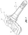
- FIG. 1illustrates a snap-in tire valve having a threaded fastener in accordance with one non-limiting aspect of the present invention
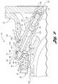
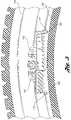
- FIG. 2illustrates a cross-sectional view of the tire valve shown
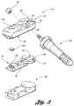
- FIG. 3illustrates an exploded view of the tire valve
- FIG. 4illustrates assembly of a sensor portion and a valve portion of the tire valve
- FIG. 5illustrates an end view of the tire valve
- FIG. 6illustrates a snap-in tire valve having a spring-clip in accordance with one non-limiting aspect of the present invention.
- FIG. 1illustrates a snap-in tire pressure monitoring system 10 in accordance with one non-limiting aspect of the present invention.
- the TPMS 10may be used to controllably regulate air pressure within a tire (not shown). As shown in the cross-sectional view of FIG. 2 , the TPMS 10 may be press-fit within an opening 12 of a tire rim 14 .
- An outer portion 18 of a valve 20may be comprised of a resilient material that allows the valve 20 to ‘snap-in’ the opening 12 .
- the resilient materialmay be a rubber or any other material having properties sufficient to forming an annular sealing surface 13 around the opening 12 that maintains air pressure within the tire.
- the air pressure within the tiremay be regulated with a valve core 22 .
- the valve 22 coremay include a reciprocating valve 24 that moves inwardly to admit or release air and that moves outwardly to seal the tire.
- the valve core 22may be threaded within a rigid, inner portion 26 of the valve 20 .
- the inner portion 26may be used to define an air passageway 28 between an inboard end (inside tire) and an outboard end (outside tire) of the valve 20 .
- the valve core 22may be use to controllable regulate air flow through the passageway 28 .
- a valve cap 30may be attached to the valve 20 to protect the valve core 22 from contaminates and other debris.
- the valve 20may be attached a sensor housing 32 .
- the sensor housing 32may include electronics 34 that measure conditions within the tire.
- the electronics 34may be mounted on a printed circuit board (PCB) 36 and configured to measure any number of conditions within the tire, such as but not limited to tire pressure, rotation speed, and/or temperature.
- FIG. 3illustrates some of the electronics 34 and the PCB 36 , which may be powered with a battery 38 .
- the battery 38may be a multi-level battery having concentric, circular portions with a top portion 40 being smaller than a bottom portion 42 .
- the sensor housing 32may include an open bottom side 44 through which the electronics 34 , PCB 36 , and battery 38 can be inserted.
- the open sensor housing 32may be filled with a potting material 46 to protect the components 34 , 36 , and 38 from contaminates.
- the electronics 34may be pre-fabricated onto the PCB 36 and then positioned within the housing 32 .
- the potting materialmay then be poured in a semi-liquid state into the housing 32 .
- a nub or channel 48may protrude from a perimeter of the housing 32 to channel the flowing potting material to a top side 50 above the battery 38 . This can be helpful in assuring the electrical isolation of the battery poles.
- the top portion 40 of the battery 38may be the negative pole such that current flows through the battery in the direction of centrifugal force, which would point in an upward direction from the bottom 44 to the top 50 of the housing.
- the top side 50 of the housing 32may include an upwardly projecting connection portion 54 , referred to as a bracket 54 .
- the bracket 54may include an opening 56 through which the inner portion 26 of the valve 20 may extend to be connected to the sensor housing 32 .
- This inboard end of the valve 20may have a solid cross-section.
- the solid cross-sectionmay provide structural support for at threaded, fastening portion 58 and a shoulder 60 that cooperate with a threaded fastener 62 to secure the valve 20 to the sensor housing 32 .
- the air passageway 28may end before the solid portion at a cross-hole 64 .
- the cross-hole 64may exchange air between the inboard and outboard sides of the tire.
- the cross-hole 64may be drilled in the same direction as the centrifugal force. This can be helpful in allow debris and other particular to be expelled from the valve 20 when the tire rotates.
- the inner valve body 26may be comprised of an electrically conducting material.
- the illustrated bodyis entirely composed of brass but portions of the body may have different materials.
- the solid, inboard endmay be made of steel to improve strength and decrease the size of the threaded fastener 62 .
- An electrical connector 66may extend between the valve 20 and the PCB 36 and/or one or more of the electronics 34 .
- the electrical connector 66can be used to electrically connect the valve 20 with the electronics 34 and/or PCB 36 , such as to support wireless data transmissions.
- the electrical connector 66is shown to wrap around a top side of the bracket 54 .
- a first side 68 of the connector 66may extend down a corresponding first side of the bracket 54 and down into the sensor housing 32 for connecting to the PCB 36 .
- a second side 70 of the connector 66may extend down a corresponding second side of the bracket 54 .
- the connector 66may be attached to the bracket 54 as part of an injection molding process used to create the housing 32 and/or after creation of the housing 32 .
- the connector 66may include wings 72 , 74 on the outboard side to facilitate its orientation.
- the connector 66may be recessed so that its second side 70 is flush with the second side of the bracket 54 .
- the connector 66may be a relative thin material that provides no structural support to the connection between the sensor housing 32 and the valve 20 .
- the first side of the connector 68may be compressed against the nut 62 and the second side 70 may be compressed against the shoulder 60 to provide multiple points of contact with the inner valve body 26 .
- the multiple points of contactmay be facilitated by molding walls 78 within the bracket opening 56 to be flush with or recessed below openings 80 , 82 on the first and second sides 68 , 70 of the connector 66 .
- the openings 56 , 80 , 82 of the bracket 54 and connector 66may be keyed with the inboard end of the valve body 26 to insure proper alignment of the cross-hole 64 , such as by including flats 86 , 88 , 90 , 92 on the valve body 26 and the openings 56 , 80 , 82 .
- Apertures 100 , 102may be included within the bracket 54 on opposite sides of the valve body 26 . As shown in FIG. 4 , the apertures 100 , 102 can be used to orientate the bottom side 44 of the sensor housing 32 with a drop well 104 of the tire. The desire orientation may set an equal gap between the drop well 104 and left and right bottom edges 106 , 108 of the housing 32 . The left and right bottom edges 106 , 108 may include feet 110 , 112 that extend below the bottom side 44 to protect the potting material 46 should the TPMS 10 rotate. Guide rails (not shown) may extend through the apertures 100 , 102 to facilitate guiding the TPMS 10 into the rim opening 12 in a manner that insures the desired orientation of the left and right bottom edges 106 , 108 .
- the TPMS 10may be positioned along the guide rails and pushed through the opening 12 from the inboard side of the tire rim 14 .
- a tool(not shown) may be attached to a threaded end 116 of the outboard portion of the valve body 26 to facilitate pulling the TPMS 10 through the opening 12 .
- the insertion methodmay be less important than insuring the proper orientation of the left and right bottoms edges 106 , 108 . If one side is improperly aligned, a portion of the top side 50 or bracket 54 could rise above a bead hump 118 of the tire. This could cause a tire tread (not shown) to strike the housing 32 during attachment, possibly disrupting operation of the electronics 34 .
- the sensor housing 32 , valve 20 , fastener 62 and other componentsmay be sized and shaped into a package that sits below the bead hump 118 , as shown in FIG. 5 .
- FIG. 2also illustrates the annular sealing surface 13 used to seal the tire after the TPMS 10 is inserted.
- the resilient nature of the outer portion 18causes it to move during insertion.
- An adhesivemay be used to secure the outer portion 18 to the inner valve body 26 .
- a ramp 122may be included at the lead edge of the resilient element 18 in an effort to limit some of the related stress. This ramp 122 may provide a leading edge 124 that cooperates with a trailing edge 126 to facilitate sealing the annual surface. Stresses may still act on the lead and trailing edges 124 , 126 after insertion.
- Cylindrical features 128 , 130may be included on the valve body 26 relative inboard and/or outboard sides of the annular sealing surface 13 to help prevent the stresses on the leading and trailing edges 124 , 126 from producing air leakage.
- a first one of the features 128may extend away from a body portion 130 to provide a surface against which a portion of the resilient element 18 between the annular sealing surface 13 and the feature 128 is compressed when the seated valve 20 (as shown in FIG. 2 ) is pressed inboard.
- a second one of the features 130may extend away from the body portion 130 to provide a surface against which a portion of the resilient element 18 between the annular sealing surface 13 and the feature 130 is compressed when the seated valve 20 is the pressed outboard.
- the engagement of the resilient element 18 against the surfaces 128 , 130resists the inboard/outboard movement. This can be helpful in preventing the centrifugal forces from raising the sensor housing 32 too far above the bead hump 118 during high speed rotation.
- the proper orientation of sensor housing 32may be useful to insure proper operation of the electronics 34 , which may perform any number of operations.
- One particular operation contemplated by one non-limiting aspect of the present inventionrelates to sensing tire pressure and wireless transmitting the sensed value to another element within the vehicle (not shown).
- the sensor housing 32may include an aperture 136 .
- a diaphragm or other pressure sensing element 138may be positioned below the aperture 136 to facilitate the pressure measurement.
- a gasket 140may be included to seal the inside of the sensor housing 32 from the exposed aperture 136 .
- one non-limiting aspect to the present inventioncontemplates a TPMS 10 having a snap-in valve portion 26 and a removably attachable sensor portion 32 .
- the attachmentmay be achieved with a nut 62 that threads directly to a rigid portion of a valve body 26 .
- An air passageway 56may end prior to a solid portion of the valve body 26 proximate the nut 62 .
- the passageway 56may continue throughout an entire length of the rigid portion 36 to provide an opening at an end of the valve body 26 beyond the nut 62 .
- Another optional featuremay include attaching a sensor housing 32 with a clip or other fastener.
- FIG. 6illustrates a clip arrangement 140 for attaching a sensor housing 142 to a valve 144 .
- a spring clip 146may fit within a slot 148 to fasten the sensor housing 142 to the valve 144 .
- the clip 146may include arms 150 , 152 that engage a bracket portion 154 .
- the bracket portion 154may be integral portion of the sensor housing 142 , as described above, or a separate piece riveted to the housing 142 , as shown in FIG. 5 .
- the bracket 154 shown in FIG. 5may be used in addition to or in place of the electrical connector 66 described above to electrically connect the electronics 34 with the valve body 26 so that the valve body 26 can be used as an antenna.
Landscapes
- Engineering & Computer Science (AREA)
- Mechanical Engineering (AREA)
- Measuring Fluid Pressure (AREA)
- Check Valves (AREA)
Abstract
Description
Claims (15)
Priority Applications (3)
| Application Number | Priority Date | Filing Date | Title |
|---|---|---|---|
| US12/184,389US8047068B2 (en) | 2008-08-01 | 2008-08-01 | Snap-in tire valve |
| DE102009035385ADE102009035385A1 (en) | 2008-08-01 | 2009-07-30 | Snap-in tire valve |
| CN200910161542.6ACN101638040B (en) | 2008-08-01 | 2009-07-31 | Snap-in tire valve |
Applications Claiming Priority (1)
| Application Number | Priority Date | Filing Date | Title |
|---|---|---|---|
| US12/184,389US8047068B2 (en) | 2008-08-01 | 2008-08-01 | Snap-in tire valve |
Publications (2)
| Publication Number | Publication Date |
|---|---|
| US20100024539A1 US20100024539A1 (en) | 2010-02-04 |
| US8047068B2true US8047068B2 (en) | 2011-11-01 |
Family
ID=41501549
Family Applications (1)
| Application Number | Title | Priority Date | Filing Date |
|---|---|---|---|
| US12/184,389Expired - Fee RelatedUS8047068B2 (en) | 2008-08-01 | 2008-08-01 | Snap-in tire valve |
Country Status (3)
| Country | Link |
|---|---|
| US (1) | US8047068B2 (en) |
| CN (1) | CN101638040B (en) |
| DE (1) | DE102009035385A1 (en) |
Cited By (12)
| Publication number | Priority date | Publication date | Assignee | Title |
|---|---|---|---|---|
| US20120204634A1 (en)* | 2011-02-14 | 2012-08-16 | San-Chuan Yu | The pressure sensor and nozzle assembly |
| JP2013244754A (en)* | 2012-05-23 | 2013-12-09 | Pacific Ind Co Ltd | Tire valve unit |
| US20150000763A1 (en)* | 2013-06-27 | 2015-01-01 | Continental Automotive Gmbh | Valve body for a snap-in valve and snap-in valve |
| US8984937B1 (en)* | 2013-03-11 | 2015-03-24 | William C. Falkenborg | Tire pressure monitoring system wheel mounting bracket |
| KR101521709B1 (en)* | 2013-10-07 | 2015-05-19 | 성정 미닛 인더스트리 씨오., 엘티디. | Tire pressure sensor |
| USD847677S1 (en)* | 2017-05-10 | 2019-05-07 | Autel Intelligent Technology Corp., Ltd. | Tire pressure monitor |
| US10429260B2 (en) | 2012-03-07 | 2019-10-01 | Alligator Ventilfabrik Gmbh | Tire pressure sensing device and method for the production thereof |
| WO2020005863A1 (en)* | 2018-06-29 | 2020-01-02 | Tyrata, Inc. | Structures and methods providing tread sensor integration |
| USD903516S1 (en)* | 2018-09-27 | 2020-12-01 | Autel Intelligent Technology Corp., Ltd. | Tire pressure sensor |
| USD904911S1 (en)* | 2018-09-27 | 2020-12-15 | Autel Intelligent Technology Corp., Ltd. | Tire pressure sensor |
| US11724553B2 (en) | 2020-02-14 | 2023-08-15 | Continental Automotive Gmbh | Valve system, tire parameter monitoring system and method for mounting a tire parameter monitoring system onto a wheel rim of a vehicle |
| USD1028761S1 (en)* | 2022-05-10 | 2024-05-28 | Shenzhen Foxwell Technology Co., Ltd | In-tire sensor |
Families Citing this family (40)
| Publication number | Priority date | Publication date | Assignee | Title |
|---|---|---|---|---|
| DE102006056470A1 (en)* | 2006-11-28 | 2008-05-29 | Alligator Ventilfabrik Gmbh | Valve assembly and kit for a valve assembly |
| IT1392131B1 (en)* | 2008-12-12 | 2012-02-22 | Wonder Spa | VALVE FOR INFLATING TIRES ASSOCIATED WITH A TRANSDUCER FOR TPMS TECHNOLOGY |
| JP4623229B1 (en)* | 2009-11-16 | 2011-02-02 | 横浜ゴム株式会社 | Transmitter for transmitting information on tire condition and tire condition monitoring system |
| RU2518151C2 (en)* | 2009-11-16 | 2014-06-10 | Дзе Йокогама Раббер Ко., Лтд. | Transmission device for transmitting tyre condition information and tyre condition monitoring system |
| JP5691275B2 (en)* | 2010-07-20 | 2015-04-01 | 横浜ゴム株式会社 | Transmitter for transmitting information on tire condition and tire condition monitoring system |
| JP4743336B1 (en)* | 2010-07-01 | 2011-08-10 | 横浜ゴム株式会社 | Transmitter for transmitting tire information and tire information monitoring system |
| JP4623231B1 (en) | 2009-11-30 | 2011-02-02 | 横浜ゴム株式会社 | Transmitter for transmitting information on tire condition and tire condition monitoring system |
| CN201751216U (en)* | 2010-06-24 | 2011-02-23 | 广东铁将军防盗设备有限公司 | Anti-collision damage reduction structure with air nozzle tire pressure gauge |
| US8516882B2 (en)* | 2010-11-15 | 2013-08-27 | Dill Air Controls Products, Llc | Tire pressure monitoring apparatuses, systems and methods |
| USD653569S1 (en)* | 2011-03-30 | 2012-02-07 | Pacific Industrial Co., Ltd. | Sensor transmitter for measuring air pressure of a tire |
| USD653570S1 (en)* | 2011-03-30 | 2012-02-07 | Pacific Industrial Co., Ltd. | Sensor transmitter for measuring air pressure of a tire |
| USD653567S1 (en)* | 2011-03-30 | 2012-02-07 | Pacific Industrial Co., Ltd. | Sensor transmitter for measuring air pressure of a tire |
| USD653568S1 (en)* | 2011-03-30 | 2012-02-07 | Pacific Industrial Co., Ltd. | Sensor transmitter for measuring air pressure of a tire |
| USD655635S1 (en)* | 2011-03-30 | 2012-03-13 | Pacific Industrial Co., Ltd. | Sensor transmitter for measuring air pressure of a tire |
| TWI499523B (en) | 2011-07-06 | 2015-09-11 | 為升電裝工業股份有限公司 | Tire pressure sensor and nozzle assembly |
| KR20130034399A (en)* | 2011-09-28 | 2013-04-05 | 삼성전기주식회사 | Tire pressure monitoring system module |
| KR20130035687A (en)* | 2011-09-30 | 2013-04-09 | 삼성전기주식회사 | TPM transmission module |
| KR20130077559A (en)* | 2011-12-29 | 2013-07-09 | 삼성전기주식회사 | Tire pressure monitoring system |
| JP2014008935A (en)* | 2012-07-02 | 2014-01-20 | Orange Electronic Co Ltd | Valve stem of radio tire pressure detector |
| FR2993823B1 (en) | 2012-07-30 | 2014-08-29 | Continental Automotive France | WHEEL MODULE COMPRISING AN ELASTICALLY DEFORMABLE INFLATION VALVE FOR A TIRE PRESSURE MONITORING SYSTEM |
| DE102012112056A1 (en) | 2012-09-20 | 2014-03-20 | Huf Hülsbeck & Fürst Gmbh & Co. Kg | Device for measuring the tire pressure in a pneumatic tire of a vehicle and wheel equipped therewith |
| FR3019097B1 (en)* | 2014-03-28 | 2018-07-06 | Continental Automotive France | ELECTRONIC UNIT FOR MEASURING OPERATING PARAMETERS OF A VEHICLE WHEEL |
| CN106604835B (en)* | 2014-05-15 | 2019-04-02 | 深圳市道通科技股份有限公司 | Tire pressure sensor assembly and wheel including the same |
| JP6175415B2 (en)* | 2014-06-26 | 2017-08-02 | 太平洋工業株式会社 | Tire valve unit |
| US9475350B2 (en)* | 2014-07-09 | 2016-10-25 | Chi-Liang Lo | Tire pressure measurement apparatus |
| CN105313609A (en)* | 2014-08-01 | 2016-02-10 | 张泽婵 | Novel tire pressure detection device with replaceable battery |
| DE102014113573A1 (en)* | 2014-09-19 | 2016-03-24 | Huf Hülsbeck & Fürst Gmbh & Co. Kg | Tire pressure monitoring system for a vehicle |
| DE102014220379B4 (en)* | 2014-10-08 | 2019-09-26 | Continental Automotive Gmbh | tire valve |
| CN104442233A (en)* | 2014-10-28 | 2015-03-25 | 芜湖赛德交通设备有限公司 | Flip-type tire pressure monitor |
| EP3225432B1 (en) | 2016-02-03 | 2019-07-03 | Pacific Industrial Co., Ltd. | Tire valve unit |
| FR3048156B1 (en)* | 2016-02-23 | 2019-11-15 | Continental Automotive France | ELECTRONIC MODULE HOUSING AND ELECTRONIC UNIT FOR MEASURING OPERATING PARAMETERS OF A VEHICLE WHEEL |
| WO2017180236A1 (en)* | 2016-04-11 | 2017-10-19 | Bridgestone Americas Tire Operations, Llc | Mounting stem for inflation valve and sensor |
| US10549183B2 (en)* | 2016-10-11 | 2020-02-04 | Valve Corporation | Electronic controller with a hand retainer, outer shell, and finger sensing |
| EP3450222B1 (en)* | 2016-12-26 | 2021-09-15 | Pacific Industrial Co., Ltd. | Tire condition detecting apparatus, clamp-in valve and tire valve unit |
| FR3086886B1 (en)* | 2018-10-03 | 2020-12-04 | Continental Automotive France | AUTOMOTIVE PNEUMATIC INFLATION VALVE |
| WO2021059470A1 (en)* | 2019-09-27 | 2021-04-01 | 太平洋工業株式会社 | Valve core |
| USD933583S1 (en)* | 2020-04-16 | 2021-10-19 | Kunshan Fuluo Auto Parts Co., Ltd. | Tire valve assembly |
| EP3939809B1 (en)* | 2020-05-29 | 2023-08-23 | Pacific Industrial Co., Ltd. | Connector and method of manufacturing a connector |
| US12269306B2 (en) | 2020-11-04 | 2025-04-08 | Pacific Industrial Co., Ltd. | Tire valve and method for producing tire valve |
| US12403731B2 (en) | 2021-09-15 | 2025-09-02 | Pacific Industrial Co., Ltd. | Tire valve |
Citations (9)
| Publication number | Priority date | Publication date | Assignee | Title |
|---|---|---|---|---|
| US6005480A (en)* | 1998-05-20 | 1999-12-21 | Schrader-Bridgeport International, Inc. | Tire valve and associated tire pressure sending unit |
| US6568259B2 (en)* | 2001-03-12 | 2003-05-27 | Pacific Industrial Co., Ltd. | Transmitter for tire condition monitoring apparatus |
| US7017403B2 (en)* | 2001-06-26 | 2006-03-28 | Beru Aktiengesellschaft | Vehicle wheel comprising a tire and an assembly consisting of a valve a device for measuring the tire pressure and a spring for holding said device in the tire |
| US7107830B1 (en)* | 2004-12-20 | 2006-09-19 | Mobiletron Electronics Co., Ltd. | Wireless tire pressure monitoring system (WTPMS) dual-sectional monitor signal transmission module |
| US7145443B2 (en)* | 2003-02-28 | 2006-12-05 | Pacific Industrial Co., Ltd. | Casing structure of transmitter for use in tire condition monitoring apparatus |
| US7395702B2 (en)* | 2006-12-04 | 2008-07-08 | Shanghai Baolong Automotive Corporation | Step-adjustable tire pressure monitoring sensor signal housing assembly |
| US7469581B2 (en)* | 2006-10-10 | 2008-12-30 | Pacific Industrial Co., Ltd. | Tire valve unit |
| US7516653B2 (en)* | 2005-11-08 | 2009-04-14 | Trw Automotive U.S. Llc | Tire pressure monitoring apparatus |
| US7568386B2 (en)* | 2006-02-02 | 2009-08-04 | Trw Automotive U.S. Llc | Tire pressure monitoring apparatus allowing for relative movement between a pressure transducer and a valve stem |
Family Cites Families (34)
| Publication number | Priority date | Publication date | Assignee | Title |
|---|---|---|---|---|
| DE4303583C2 (en)* | 1993-02-08 | 1996-02-22 | Alpha Beta Electronics Ag | Valve with a device for generating a wirelessly transmitted pressure decrease signal for vehicle tires |
| US6247513B1 (en)* | 1993-10-08 | 2001-06-19 | J.C. Ludowici & Son Ltd. | Pressure indicating tire inflation valve |
| US5844131A (en)* | 1995-06-26 | 1998-12-01 | Alligator Ventilfabrik Gmbh | Tire pressure sensor apparatus for a pneumatic tire of a vehicle |
| DE19626145A1 (en)* | 1996-07-01 | 1998-01-08 | Continental Ag | Fastening device for an electronic module |
| JP3317905B2 (en)* | 1998-09-07 | 2002-08-26 | 太平洋工業株式会社 | Casing structure of transmitter for tire pressure warning device |
| US6418786B1 (en)* | 1998-10-13 | 2002-07-16 | Larry W. Holcomb | Aircheck safety valve |
| US6055855A (en)* | 1999-05-26 | 2000-05-02 | Trw Inc. | Tire pressure sensor wheel attachment apparatus |
| TW520332B (en)* | 2000-09-02 | 2003-02-11 | Lite On Automotive Corp | Status sensor of inflated automobile tire |
| ES2280456T3 (en)* | 2001-07-19 | 2007-09-16 | Alligator Ventilfabrik Gmbh | DEVICE FOR PRESSURE MEASUREMENT IN A VEHICLE TIRE. |
| FR2828657B1 (en)* | 2001-08-16 | 2003-11-21 | Siemens Automotive Sa | PRESSURE SENSOR FOR MOUNTING IN A TIRE |
| FR2829063B1 (en)* | 2001-09-06 | 2003-10-31 | Siemens Vdo Automotive Sas | DEVICE FOR MOUNTING A SENSOR ON A MOTOR VEHICLE WHEEL RIM AND ASSOCIATED MOUNTING METHOD |
| FR2831486B1 (en)* | 2001-10-29 | 2003-12-19 | Siemens Vdo Automotive | PRESSURE SENSOR INTENDED TO BE MOUNTED IN A TIRE AND ITS SUPPORT |
| JP2003165314A (en)* | 2001-11-28 | 2003-06-10 | Pacific Ind Co Ltd | Casing structure for transmitter for tire air pressure alarm device |
| JP2003182322A (en)* | 2001-12-19 | 2003-07-03 | Pacific Ind Co Ltd | Transmitter of tyre state monitoring device |
| FR2834245B1 (en)* | 2001-12-28 | 2005-07-15 | Siemens Vdo Automotive | DEVICE FOR MOUNTING A SENSOR ON A WHEEL RIM AND CORRESPONDING METHOD |
| DE10228737A1 (en)* | 2002-01-09 | 2003-07-24 | Lite On Automotive Corp | Tire condition sensor for pneumatic tires |
| ITMI20020344A1 (en)* | 2002-02-20 | 2003-08-20 | Polenghi Mario S R L | VALVE-DEVICE TO MEASURE THE PRESSURE OF A TIRE |
| AU2003230704A1 (en)* | 2002-03-21 | 2003-10-08 | Frank S. Banzhof | Tire pressure monitor with thin-walled valve cap |
| FR2839470B1 (en)* | 2002-05-07 | 2005-02-11 | Siemens Vdo Automotive | DEVICE FOR FASTENING A PRESSURE SENSOR FOR MOUNTING IN A TIRE |
| US6959597B2 (en)* | 2002-08-01 | 2005-11-01 | Pacific Industrial Co., Ltd. | Transmitter for tire state monitoring apparatus |
| US6722409B1 (en)* | 2002-11-04 | 2004-04-20 | Eaton Corporation | Snap in valve stem |
| JP2004203151A (en)* | 2002-12-24 | 2004-07-22 | Pacific Ind Co Ltd | Valve for transmitter of tire condition monitoring device |
| JP2004294413A (en)* | 2003-02-12 | 2004-10-21 | Pacific Ind Co Ltd | Pressure sensor, transmitter, and tire condition monitor |
| JP2004255916A (en)* | 2003-02-24 | 2004-09-16 | Pacific Ind Co Ltd | Mounting structure of transmitter for tire condition monitoring device |
| JP4031742B2 (en)* | 2003-08-27 | 2008-01-09 | 太平洋工業株式会社 | Casing structure of transmitter for tire condition monitoring device |
| JP2005067543A (en)* | 2003-08-27 | 2005-03-17 | Pacific Ind Co Ltd | Transmitter casing structure for tire condition monitoring device |
| JP2006151295A (en)* | 2004-11-30 | 2006-06-15 | Pacific Ind Co Ltd | Snap-in valve device |
| US20060196259A1 (en)* | 2005-03-02 | 2006-09-07 | Chin-Yao Hsu | Aerial of wireless tire pressure monitoring device |
| US7281421B2 (en)* | 2005-06-03 | 2007-10-16 | Temic Automotive Of North America, Inc. | Package for a tire pressure sensor assembly |
| US7284418B2 (en)* | 2005-06-03 | 2007-10-23 | Temic Automotive Of North America, Inc. | Tire pressure sensor assembly |
| US7021133B1 (en)* | 2005-06-16 | 2006-04-04 | Lite-On Automotive Corp. | Tire condition sensing apparatus and mounting method thereof |
| CN2826556Y (en)* | 2005-08-09 | 2006-10-11 | 深圳市航盛电子股份有限公司 | External tire-pressure monitoring transmitter |
| US7916011B2 (en)* | 2006-01-23 | 2011-03-29 | Schrader Electronics Ltd. | Tire monitor system having tire valve antenna |
| CN200988401Y (en)* | 2006-11-29 | 2007-12-12 | 上海保隆汽车科技股份有限公司 | Combined device of stepless adjustable tire pressure monitoring sensor signal box |
- 2008
- 2008-08-01USUS12/184,389patent/US8047068B2/ennot_activeExpired - Fee Related
- 2009
- 2009-07-30DEDE102009035385Apatent/DE102009035385A1/ennot_activeWithdrawn
- 2009-07-31CNCN200910161542.6Apatent/CN101638040B/ennot_activeExpired - Fee Related
Patent Citations (10)
| Publication number | Priority date | Publication date | Assignee | Title |
|---|---|---|---|---|
| US6005480A (en)* | 1998-05-20 | 1999-12-21 | Schrader-Bridgeport International, Inc. | Tire valve and associated tire pressure sending unit |
| US6163255A (en)* | 1998-05-20 | 2000-12-19 | Schrader-Bridgeport International, Inc. | Tire valve and associated tire pressure sending unit |
| US6568259B2 (en)* | 2001-03-12 | 2003-05-27 | Pacific Industrial Co., Ltd. | Transmitter for tire condition monitoring apparatus |
| US7017403B2 (en)* | 2001-06-26 | 2006-03-28 | Beru Aktiengesellschaft | Vehicle wheel comprising a tire and an assembly consisting of a valve a device for measuring the tire pressure and a spring for holding said device in the tire |
| US7145443B2 (en)* | 2003-02-28 | 2006-12-05 | Pacific Industrial Co., Ltd. | Casing structure of transmitter for use in tire condition monitoring apparatus |
| US7107830B1 (en)* | 2004-12-20 | 2006-09-19 | Mobiletron Electronics Co., Ltd. | Wireless tire pressure monitoring system (WTPMS) dual-sectional monitor signal transmission module |
| US7516653B2 (en)* | 2005-11-08 | 2009-04-14 | Trw Automotive U.S. Llc | Tire pressure monitoring apparatus |
| US7568386B2 (en)* | 2006-02-02 | 2009-08-04 | Trw Automotive U.S. Llc | Tire pressure monitoring apparatus allowing for relative movement between a pressure transducer and a valve stem |
| US7469581B2 (en)* | 2006-10-10 | 2008-12-30 | Pacific Industrial Co., Ltd. | Tire valve unit |
| US7395702B2 (en)* | 2006-12-04 | 2008-07-08 | Shanghai Baolong Automotive Corporation | Step-adjustable tire pressure monitoring sensor signal housing assembly |
Cited By (16)
| Publication number | Priority date | Publication date | Assignee | Title |
|---|---|---|---|---|
| US8539826B2 (en)* | 2011-02-14 | 2013-09-24 | Cub Elecparts Inc. | Pressure sensor and nozzle assembly |
| US20120204634A1 (en)* | 2011-02-14 | 2012-08-16 | San-Chuan Yu | The pressure sensor and nozzle assembly |
| US10429260B2 (en) | 2012-03-07 | 2019-10-01 | Alligator Ventilfabrik Gmbh | Tire pressure sensing device and method for the production thereof |
| JP2013244754A (en)* | 2012-05-23 | 2013-12-09 | Pacific Ind Co Ltd | Tire valve unit |
| US8984937B1 (en)* | 2013-03-11 | 2015-03-24 | William C. Falkenborg | Tire pressure monitoring system wheel mounting bracket |
| JP2015010714A (en)* | 2013-06-27 | 2015-01-19 | コンチネンタル オートモーティヴ ゲゼルシャフト ミット ベシュレンクテル ハフツングContinental Automotive GmbH | Valve body for snap-in valve, and snap-in valve |
| US20150000763A1 (en)* | 2013-06-27 | 2015-01-01 | Continental Automotive Gmbh | Valve body for a snap-in valve and snap-in valve |
| KR101521709B1 (en)* | 2013-10-07 | 2015-05-19 | 성정 미닛 인더스트리 씨오., 엘티디. | Tire pressure sensor |
| USD847677S1 (en)* | 2017-05-10 | 2019-05-07 | Autel Intelligent Technology Corp., Ltd. | Tire pressure monitor |
| USD873162S1 (en)* | 2017-05-10 | 2020-01-21 | Autel Intelligent Technology Corp. Ltd. | Tire pressure monitor |
| WO2020005863A1 (en)* | 2018-06-29 | 2020-01-02 | Tyrata, Inc. | Structures and methods providing tread sensor integration |
| US11673436B2 (en) | 2018-06-29 | 2023-06-13 | Tyrata, Inc. | Structures and methods providing tread sensor integration |
| USD903516S1 (en)* | 2018-09-27 | 2020-12-01 | Autel Intelligent Technology Corp., Ltd. | Tire pressure sensor |
| USD904911S1 (en)* | 2018-09-27 | 2020-12-15 | Autel Intelligent Technology Corp., Ltd. | Tire pressure sensor |
| US11724553B2 (en) | 2020-02-14 | 2023-08-15 | Continental Automotive Gmbh | Valve system, tire parameter monitoring system and method for mounting a tire parameter monitoring system onto a wheel rim of a vehicle |
| USD1028761S1 (en)* | 2022-05-10 | 2024-05-28 | Shenzhen Foxwell Technology Co., Ltd | In-tire sensor |
Also Published As
| Publication number | Publication date |
|---|---|
| DE102009035385A1 (en) | 2010-02-11 |
| US20100024539A1 (en) | 2010-02-04 |
| CN101638040B (en) | 2012-08-29 |
| CN101638040A (en) | 2010-02-03 |
Similar Documents
| Publication | Publication Date | Title |
|---|---|---|
| US8047068B2 (en) | Snap-in tire valve | |
| US7669466B2 (en) | Monitoring device attachment to rubber valve stems | |
| CN113804342B (en) | Pressure measuring device | |
| US8988209B2 (en) | Device for monitoring a vehicle wheel | |
| US8863570B2 (en) | Support and insert for attaching a module to a tire wall | |
| US8303742B2 (en) | Tyre comprising an electronic unit and a method of installing said electronic unit into said tyre | |
| US7281421B2 (en) | Package for a tire pressure sensor assembly | |
| US10549586B1 (en) | Electronic unit for measuring operating parameters of a vehicle wheel | |
| US10429260B2 (en) | Tire pressure sensing device and method for the production thereof | |
| JP2002264621A (en) | Transmitter of tire condition monitoring device | |
| US11813900B2 (en) | Housing for a tyre parameter monitoring system, tyre parameter monitoring system and method for mounting a tyre parameter monitoring system to a rim of a wheel | |
| CN113263875B (en) | Valve system, tire parameter monitoring system and method of mounting a tire parameter monitoring system to a rim of a vehicle | |
| EP1452347A3 (en) | Casing structure of transmitter for use in tire condition monitoring apparatus | |
| CN111670126B (en) | Electronic unit for measuring operating parameters of vehicle wheels comprising electronic box and inflation valve of elastically deformable type | |
| US7336162B2 (en) | Double mold shot pull to seat universal TPMS sensor | |
| GB2580379A (en) | Housing for a tyre parameter monitoring system, tyre parameter monitoring system and method for mounting a tyre parameter monitoring system | |
| CN112238714B (en) | Commercial car TPMS inflating valve and TPMS sensor partial shipment | |
| CN104417293A (en) | Tire pressure sensor | |
| JP5305647B2 (en) | Electronic unit for measuring the operating parameters of wheels | |
| CN201304865Y (en) | Tire valve on which tire pressure monitoring system electronic box can be mounted | |
| EP4601886A1 (en) | Tire monitoring apparatus, system, and methods | |
| US20040182490A1 (en) | Tire valve nut and tire valve | |
| US20080184786A1 (en) | Wheel sensor with valve |
Legal Events
| Date | Code | Title | Description |
|---|---|---|---|
| AS | Assignment | Owner name:LEAR CORPORATION,MICHIGAN Free format text:ASSIGNMENT OF ASSIGNORS INTEREST;ASSIGNORS:HAMM, LAWRENCE W.;ULESKI, MICHAEL A.;REEL/FRAME:021333/0752 Effective date:20080801 Owner name:LEAR CORPORATION, MICHIGAN Free format text:ASSIGNMENT OF ASSIGNORS INTEREST;ASSIGNORS:HAMM, LAWRENCE W.;ULESKI, MICHAEL A.;REEL/FRAME:021333/0752 Effective date:20080801 | |
| AS | Assignment | Owner name:JPMORGAN CHASE BANK, N.A., AS ADMINISTRATIVE AGENT Free format text:GRANT OF FIRST LIEN SECURITY INTEREST IN PATENT RIGHTS;ASSIGNOR:LEAR CORPORATION;REEL/FRAME:023519/0267 Effective date:20091109 Owner name:JPMORGAN CHASE BANK, N.A., AS ADMINISTRATIVE AGENT Free format text:GRANT OF SECOND LIEN SECURITY INTEREST IN PATENT RIGHTS;ASSIGNOR:LEAR CORPORATION;REEL/FRAME:023519/0626 Effective date:20091109 | |
| AS | Assignment | Owner name:LEAR CORPORATION, MICHIGAN Free format text:RELEASE BY SECURED PARTY;ASSIGNOR:JPMORGAN CHASE BANK, N.A.;REEL/FRAME:025008/0265 Effective date:20100830 | |
| AS | Assignment | Owner name:LEAR CORPORATION, MICHIGAN Free format text:RELEASE BY SECURED PARTY;ASSIGNOR:JPMORGAN CHASE BANK, N.A.;REEL/FRAME:025227/0340 Effective date:20101101 | |
| AS | Assignment | Owner name:SCHRADER ELECTRONICS, INC., MICHIGAN Free format text:ASSIGNMENT OF ASSIGNORS INTEREST;ASSIGNOR:LEAR CORPORATION;REEL/FRAME:025552/0575 Effective date:20101101 | |
| AS | Assignment | Owner name:BARCLAYS BANK PLC, NEW YORK Free format text:SECURITY AGREEMENT;ASSIGNOR:SCHRADER ELECTRONICS, INC.;REEL/FRAME:028118/0079 Effective date:20120427 Owner name:BARCLAYS BANK PLC, NEW YORK Free format text:SECURITY AGREEMENT;ASSIGNOR:SCHRADER ELECTRONICS, INC.;REEL/FRAME:028117/0677 Effective date:20120427 | |
| AS | Assignment | Owner name:BARCLAYS BANK PLC, NEW YORK Free format text:AMENDED AND RESTATED SECURITY INTEREST;ASSIGNOR:SCHRADER ELECTRONICS, INC.;REEL/FRAME:030487/0209 Effective date:20130523 | |
| AS | Assignment | Owner name:LEAR CORPORATION, MICHIGAN Free format text:RELEASE BY SECURED PARTY;ASSIGNOR:JPMORGAN CHASE BANK, N.A.;REEL/FRAME:032770/0843 Effective date:20100830 | |
| AS | Assignment | Owner name:SCHRADER ELECTRONICS, INC., TENNESSEE Free format text:RELEASE OF FIRST LIEN SECURITY INTEREST;ASSIGNOR:BARCLAYS BANK PLC;REEL/FRAME:034012/0051 Effective date:20141014 Owner name:SCHRADER-BRIDGEPORT INTERNATIONAL, INC., VIRGINIA Free format text:RELEASE OF FIRST LIEN SECURITY INTEREST;ASSIGNOR:BARCLAYS BANK PLC;REEL/FRAME:034012/0051 Effective date:20141014 Owner name:SCHRADER ELECTRONICS LIMITED, NORTHERN IRELAND Free format text:RELEASE OF FIRST LIEN SECURITY INTEREST;ASSIGNOR:BARCLAYS BANK PLC;REEL/FRAME:034012/0051 Effective date:20141014 Owner name:SCHRADER-BRIDGEPORT INTERNATIONAL, INC., VIRGINIA Free format text:RELEASE OF SECOND LIEN SECURITY INTEREST;ASSIGNOR:BARCLAYS BANK PLC;REEL/FRAME:034012/0290 Effective date:20141014 Owner name:SCHRADER ELECTRONICS, INC., TENNESSEE Free format text:RELEASE OF SECOND LIEN SECURITY INTEREST;ASSIGNOR:BARCLAYS BANK PLC;REEL/FRAME:034012/0290 Effective date:20141014 Owner name:SCHRADER ELECTRONICS LIMITED, NORTHERN IRELAND Free format text:RELEASE OF SECOND LIEN SECURITY INTEREST;ASSIGNOR:BARCLAYS BANK PLC;REEL/FRAME:034012/0290 Effective date:20141014 | |
| REMI | Maintenance fee reminder mailed | ||
| LAPS | Lapse for failure to pay maintenance fees | ||
| STCH | Information on status: patent discontinuation | Free format text:PATENT EXPIRED DUE TO NONPAYMENT OF MAINTENANCE FEES UNDER 37 CFR 1.362 | |
| FP | Lapsed due to failure to pay maintenance fee | Effective date:20151101 | |
| AS | Assignment | Owner name:LEAR CORPORATION, MICHIGAN Free format text:RELEASE BY SECURED PARTY;ASSIGNOR:JPMORGAN CHASE BANK, N.A., AS AGENT;REEL/FRAME:037701/0180 Effective date:20160104 Owner name:LEAR CORPORATION, MICHIGAN Free format text:RELEASE BY SECURED PARTY;ASSIGNOR:JPMORGAN CHASE BANK, N.A., AS AGENT;REEL/FRAME:037701/0251 Effective date:20160104 Owner name:LEAR CORPORATION, MICHIGAN Free format text:RELEASE BY SECURED PARTY;ASSIGNOR:JPMORGAN CHASE BANK, N.A., AS AGENT;REEL/FRAME:037701/0340 Effective date:20160104 | |
| AS | Assignment | Owner name:AUGUST U.S. HOLDING COMPANY, INC., DELAWARE Free format text:MERGER;ASSIGNOR:SCHRADER ELECTRONICS, INC.;REEL/FRAME:045450/0704 Effective date:20161212 | |
| AS | Assignment | Owner name:SENSATA TECHNOLOGIES, INC., MASSACHUSETTS Free format text:MERGER;ASSIGNOR:AUGUST U.S. HOLDING COMPANY, INC.;REEL/FRAME:045458/0486 Effective date:20161212 |