US8045935B2 - High data rate transmitter and receiver - Google Patents
High data rate transmitter and receiverDownload PDFInfo
- Publication number
- US8045935B2 US8045935B2US11/055,525US5552505AUS8045935B2US 8045935 B2US8045935 B2US 8045935B2US 5552505 AUS5552505 AUS 5552505AUS 8045935 B2US8045935 B2US 8045935B2
- Authority
- US
- United States
- Prior art keywords
- data
- signal
- sub
- channel
- transmitter
- Prior art date
- Legal status (The legal status is an assumption and is not a legal conclusion. Google has not performed a legal analysis and makes no representation as to the accuracy of the status listed.)
- Expired - Lifetime, expires
Links
Images


Classifications
- H—ELECTRICITY
- H04—ELECTRIC COMMUNICATION TECHNIQUE
- H04B—TRANSMISSION
- H04B1/00—Details of transmission systems, not covered by a single one of groups H04B3/00 - H04B13/00; Details of transmission systems not characterised by the medium used for transmission
- H04B1/69—Spread spectrum techniques
- H04B1/7163—Spread spectrum techniques using impulse radio
- H04B1/71637—Receiver aspects
- H—ELECTRICITY
- H04—ELECTRIC COMMUNICATION TECHNIQUE
- H04B—TRANSMISSION
- H04B1/00—Details of transmission systems, not covered by a single one of groups H04B3/00 - H04B13/00; Details of transmission systems not characterised by the medium used for transmission
- H04B1/69—Spread spectrum techniques
- H04B1/7163—Spread spectrum techniques using impulse radio
- H04B1/71632—Signal aspects
- H—ELECTRICITY
- H04—ELECTRIC COMMUNICATION TECHNIQUE
- H04B—TRANSMISSION
- H04B1/00—Details of transmission systems, not covered by a single one of groups H04B3/00 - H04B13/00; Details of transmission systems not characterised by the medium used for transmission
- H04B1/69—Spread spectrum techniques
- H04B1/7163—Spread spectrum techniques using impulse radio
- H04B1/71635—Transmitter aspects
Definitions
- the inventionrelates generally to communications, and more particularly to systems and methods for high data rate communications.
- Wireless communication systemsare proliferating at the Wide Area Network (WAN), Local Area Network (LAN), and Personal Area Network (PAN) levels. These wireless communication systems use a variety of techniques to allow simultaneous access to multiple users. The most common of these techniques are Frequency Division Multiple Access (FDMA), which assigns specific frequencies to each user, Time Division Multiple Access (TDMA), which assigns particular time slots to each user, and Code Division Multiple Access (CDMA), which assigns specific codes to each user.
- FDMAFrequency Division Multiple Access
- TDMATime Division Multiple Access
- CDMACode Division Multiple Access
- these wireless communication systems and various modulation techniquesare afflicted by a host of problems that limit the capacity and the quality of service provided to the users. The following paragraphs briefly describe a few of these problems for the purpose of illustration.
- Multipath interferenceoccurs because some of the energy in a transmitted wireless signal bounces off of obstacles, such as buildings or mountains, as it travels from source to destination. The obstacles in effect create reflections of the transmitted signal and the more obstacles there are, the more reflections they generate. The reflections then travel along their own transmission paths to the destination (or receiver). The reflections will contain the same information as the original signal; however, because of the differing transmission path lengths, the reflected signals will be out of phase with the original signal. As a result, they will often combine destructively with the original signal in the receiver. This is referred to as fading. To combat fading, current systems typically try to estimate the multipath effects and then compensate for them in the receiver using an equalizer. In practice, however, it is very difficult to achieve effective multipath compensation.
- a second problem that can affect the operation of wireless communication systemsis interference from adjacent communication cells within the system.
- this type of interferenceis prevent through a frequency reuse plan.
- available communication frequenciesare allocated to communication cells within the communication system such that the same frequency will not be used in adjacent cells. Essentially, the available frequencies are split into groups. The number of groups is termed the reuse factor.
- the communication cellsare grouped into clusters, each cluster containing the same number of cells as there are frequency groups. Each frequency group is then assigned to a cell in each cluster.
- a frequency reuse factor of 7is used, for example, then a particular communication frequency will be used only once in every seven communication cells.
- each cellcan only use 1/7 th of the available frequencies, i.e., each cell is only able to use 1/7 th of the available bandwidth.
- each celluses the same wideband communication channel.
- each communication celluses a particular set of spread spectrum codes to differentiate communications within the cell from those originating outside of the cell.
- CDMA systemspreserve the bandwidth in the sense that they avoid reuse planning. But as will be discussed, there are other issues that limit the bandwidth in CDMA systems as well.
- Wireless communication systemscan be split into three types: 1) line-of-sight systems, which can include point-to-point or point-to-multipoint systems; 2) indoor non-line of sight systems; and 3) outdoor systems such as wireless WANs.
- Line-of-sight systemsare least affected by the problems described above, while indoor systems are more affected, due for example to signals bouncing off of building walls. Outdoor systems are by far the most affected of the three systems. Because these types of problems are limiting factors in the design of wireless transmitters and receivers, such designs must be tailored to the specific types of system in which it will operate.
- each type of systemimplements unique communication standards that address the issues unique to the particular type of system. Even if an indoor system used the same communication protocols and modulation techniques as an outdoor system, for example, the receiver designs would still be different because multipath and other problems are unique to a given type of system and must be addressed with unique solutions. This would not necessarily be the case if cost efficient and effective methodologies can be developed to combat such problems as described above that build in programmability so that a device can be reconfigured for different types of systems and still maintain superior performance.
- a transmittercomprises a baseband processor structured to receive data and to convert the data into a multiplicity of high and low signal values, with each high and low signal value having a first timing interval.
- a local oscillatorgenerates a clock signal at a second timing interval and a digital circuit combines the high and low signal values with the clock signal to produce a transmission signal directly at a transmission frequency.
- the radio frequency used for transmissionmay range up to 11 Giga-Hertz, and production of the transmission signal directly at the transmission frequency is possible by use of a high-speed oscillator.
- a receiveris structured to receive the communication signal, which in one embodiment, may have a fractional bandwidth that may range between approximately 20 percent and approximately 200 percent.
- the receiverincludes a high-speed analog to digital converter configured to directly convert the radio frequency signal into a data signal.
- FIG. 1Ais a diagram illustrating an example embodiment of a wideband channel divided into a plurality of sub-channels in accordance with the invention
- FIG. 1Bis a diagram illustrating the effects of multipath in a wireless communication system
- FIG. 2is a diagram illustrating another example embodiment of a wideband communication channel divided into a plurality of sub-channels in accordance with the invention
- FIG. 3is a diagram illustrating the application of a roll-off factor to the sub-channels of FIGS. 1 and 2 ;
- FIG. 4Ais a diagram illustrating the assignment of sub-channels for a wideband communication channel in accordance with the invention.
- FIG. 4Bis a diagram illustrating the assignment of time slots for a wideband communication channel in accordance with the invention.
- FIG. 5is a diagram illustrating an example embodiment of a wireless communication in accordance with the invention.
- FIG. 6is a diagram illustrating the use of synchronization codes in the wireless communication system of FIG. 5 in accordance with the invention.
- FIG. 7is a diagram illustrating a correlator that can be used to correlate synchronization codes in the wireless communication system of FIG. 5 ;
- FIG. 8is a diagram illustrating synchronization code correlation in accordance with the invention.
- FIG. 9is a diagram illustrating the cross-correlation properties of synchronization codes configured in accordance with the invention.
- FIG. 10is a diagram illustrating another example embodiment of a wireless communication system in accordance with the invention.
- FIG. 11Ais a diagram illustrating how sub-channels of a wideband communication channel according to the present invention can be grouped in accordance with the present invention
- FIG. 11Bis a diagram illustrating the assignment of the groups of sub-channels of FIG. 11A in accordance with the invention.
- FIG. 12is a diagram illustrating the group assignments of FIG. 11B in the time domain
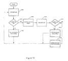
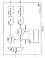
- FIG. 13is a flow chart illustrating the assignment of sub-channels based on SIR measurements in the wireless communication system of FIG. 10 in accordance with the invention
- FIG. 14is a logical block diagram of an example embodiment of transmitter configured in accordance with the invention.
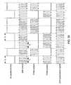
- FIG. 15is a logical block diagram of an example embodiment of a modulator configured in accordance with the present invention for use in the transmitter of FIG. 14 ;
- FIG. 16is a diagram illustrating an example embodiment of a rate controller configured in accordance with the invention for use in the modulator of FIG. 15 ;
- FIG. 17is a diagram illustrating another example embodiment of a rate controller configured in accordance with the invention for use in the modulator of FIG. 15 ;
- FIG. 18is a diagram illustrating an example embodiment of a frequency encoder configured in accordance with the invention for use in the modulator of FIG. 15 ;
- FIG. 19is a logical block diagram of an example embodiment of a TDM/FDM block configured in accordance with the invention for use in the modulator of FIG. 15 ;
- FIG. 20is a logical block diagram of another example embodiment of a TDM/FDM block configured in accordance with the invention for use in the modulator of FIG. 15 ;
- FIG. 21is a logical block diagram of an example embodiment of a frequency shifter configured in accordance with the invention for use in the modulator of FIG. 15 ;
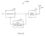
- FIG. 22is a logical block diagram of a receiver configured in accordance with the invention.
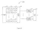
- FIG. 23is a logical block diagram of an example embodiment of a demodulator configured in accordance with the invention for use in the receiver of FIG. 22 ;
- FIG. 24is a logical block diagram of an example embodiment of an equalizer configured in accordance with the present invention for use in the demodulator of FIG. 23 ;
- FIG. 25is a logical block diagram of an example embodiment of a wireless communication device configured in accordance with the invention.
- FIG. 26is an illustration of different communication methods
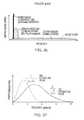
- FIG. 27is an illustration of two ultra-wideband pulses
- FIG. 28is a chart of ultra-wideband emission limits as established by the Federal Communications Commission on Apr. 22, 2002;
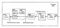
- FIG. 29illustrates a transmitter consistent with one embodiment of the present invention
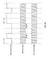
- FIG. 30illustrates a timing diagram of various signals
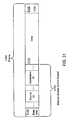
- FIG. 31illustrates a frame consistent with one embodiment of the present invention
- FIG. 32 aillustrates one embodiment of a digital circuit employed in the transmitter of FIG. 29 ;
- FIG. 32 billustrates a second embodiment of a digital circuit employed in the transmitter of FIG. 29 ;
- FIG. 32 cillustrates a third embodiment of a digital circuit employed in the transmitter of FIG. 29 ;
- FIG. 33illustrates a data stream consistent with one embodiment of the present invention
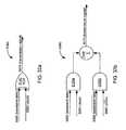
- FIG. 34illustrates a receiver consistent with one embodiment of the present invention
- FIG. 35illustrates a schematic of a first portion of a baseband processor employed in the transmitter of FIG. 29 ;
- FIG. 36illustrates a schematic of a second portion of a baseband processor employed in the receiver of FIG. 34 ;
- FIG. 37illustrates one embodiment of a poly-phase filter employed in the baseband processor of FIG. 36 ;
- FIG. 38illustrates another embodiment of a poly-phase filter employed in the baseband processor of FIG. 36 ;
- FIG. 39illustrates another timing diagram of signals consistent with the present invention.
- FIG. 40illustrates one embodiment of an equalizer consistent with the present invention
- FIG. 41illustrates an exemplary FEC encoder and exemplary FEC decoder
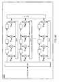
- FIG. 42illustrates an example FEC encoder configured in accordance with one embodiment of the present invention
- FIG. 43illustrates a FEC encoder configured to generate a code word from input data in accordance with one embodiment
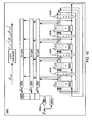
- FIG. 44illustrates the encoder of FIG. 42 in more detail
- FIG. 45illustrates further detail for the encoder of FIG. 42 ;
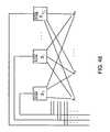
- FIG. 46illustrates an example parity node processor that can be included in a decoder in accordance with one embodiment
- FIG. 47illustrates one node of the parity node processor of FIG. 45 ;
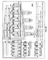
- FIG. 48illustrates the parity node processor of FIG. 45 in more detail.
- FIG. 49illustrates a parity node processor configured in accordance with one embodiment.
- the systems and methods described hereinprovide various communication methodologies that enhance performance of transmitters and receivers with regard to various common problems that afflict such systems and that allow the transmitters and/or receivers to be reconfigured for optimal performance in a variety of systems.
- the systems and methods described hereindefine a channel access protocol that uses a common wideband communication channel for all communication cells.
- the wideband channelis then divided into a plurality of sub-channels. Different sub-channels are then assigned to one or more users within each cell. But the base station, or service access point, within each cell transmits one message that occupies the entire bandwidth of the wideband channel.
- Each user's communication devicereceives the entire message, but only decodes those portions of the message that reside in sub-channels assigned to the user.
- sub-channelsFor a point-to-point system, for example, a single user may be assigned all sub-channels and, therefore, has the full wide band channel available to them.
- the sub-channelsmay be divided among a plurality of users.
- Communications sent over channel 100 in a traditional wireless communication systemwill comprise digital data bits, or symbols, that are encoded and modulated onto a RF carrier that is centered at frequency f c and occupies bandwidth B.
- the width of the symbols (or the symbol duration) Tis defined as 1/B.
- a receiverWhen a receiver receives the communication, demodulates it, and then decodes it, it will recreate a stream 104 of data symbols 106 as illustrated in FIG. 1B . But the receiver will also receive multipath versions 108 of the same data stream. Because multipath data streams 108 are delayed in time relative to the data stream 104 by delays d 1 , d 2 , d 3 , and d 4 , for example, they may combine destructively with data stream 104 .
- a delay spread d sis defined as the delay from reception of data stream 104 to the reception of the last multipath data stream 108 that interferes with the reception of data stream 104 .
- the delay spread d sis equal to delay d 4 .
- the delay spread d swill vary for different environments. An environment with a lot of obstacles will create a lot of multipath reflections. Thus, the delay spread d s will be longer. Experiments have shown that for outdoor WAN type environments, the delay spread d s can be as long as 20 microseconds. Using the 10 ns symbol duration of equation (1), this translates to 2000 symbols.
- multipath interferencecan cause a significant amount of interference at the symbol level for which adequate compensation is difficult to achieve. This is true even for indoor environments.
- the delay spread d sis significantly shorter, typically about 1 microsecond. For a 10 ns symbol duration, this is equivalent to 100 symbols, which is more manageable but still significant.
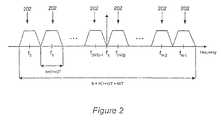
- the multipath effectcan be reduced to a much more manageable level. For example, if the bandwidth b of each sub-channel 202 is 500 KHz, then the symbol duration is 2 microseconds. Thus, the delay spread d s for each sub-channel is equivalent to only 10 symbols (outdoor) or half a symbol (indoor). Thus, by breaking up a message that occupies the entire bandwidth B into discrete messages, each occupying the bandwidth b of sub-channels 202 , a very wideband signal that suffers from relatively minor multipath effects is created.
- the overall bandwidth Bis segmented into N sub-channels center at frequencies f o to f N ⁇ 1 .
- the sub-channel 202 that is immediately to the right of fcis offset from fc by b/2, where b is the bandwidth of each sub-channel 202 .
- the next sub-channel 202is offset by 3b/2, the next by 5b/2, and so on.
- each sub-channel 202is offset by ⁇ b/2, ⁇ 3b/2, ⁇ 5b/2, etc.
- sub-channels 202are non-overlapping as this allows each sub-channel to be processed independently in the receiver.
- a roll-off factoris preferably applied to the signals in each sub-channel in a pulse-shaping step.
- the effect of such a pulse-shaping stepis illustrated in FIG. 2 by the non-rectangular shape of the pulses in each sub-channel 202 .
- the pulse shapewould be rectangular in the frequency domain, which corresponds to a (sin x)/x function in the time domain.
- the time domain signal for a (sin x)/x signal 400is shown in FIG. 3 in order to illustrate the problems associated with a rectangular pulse shape and the need to use a roll-off factor.
- main lobe 402comprises almost all of signal 400 . But some of the signal also resides in side lobes 404 , which stretch out indefinitely in both directions from main lobe 402 . Side lobes 404 make processing signal 400 much more difficult, which increases the complexity of the receiver.
- Applying a roll-off factor r, as in equation (2),causes signal 400 to decay faster, reducing the number of side lobes 404 .
- increasing the roll-off factordecreases the length of signal 400 , i.e., signal 400 becomes shorter in time.
- including the roll-off factoralso decreases the available bandwidth in each sub-channel 202 . Therefore, r must be selected so as to reduce the number of side lobes 404 to a sufficient number, e.g., 15, while still maximizing the available bandwidth in each sub-channel 202 .
- IFFTInverse Fast Fourier Transform
- FIG. 5illustrates an example communication system 600 comprising a plurality of cells 602 that each use a common wideband communication channel to communicate with communication devices 604 within each cell 602 .
- the common communication channelis a wideband communication channel as described above.
- Each communication cell 602is defined as the coverage area of a base station, or service access point, 606 within the cell.
- One such base station 606is shown for illustration in FIG. 5 .
- the term base stationwill be used generically to refer to a device that provides wireless access to the wireless communication system for a plurality of communication devices, whether the system is a line of sight, indoor, or outdoor system.
- each cell 602uses the same communication channel, signals in one cell 602 must be distinguishable from signals in adjacent cells 602 .
- adjacent base stations 606use different synchronization codes according to a code reuse plan.
- system 600uses a synchronization code reuse factor of 4, although the reuse factor can vary depending on the application.
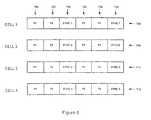
- the synchronization codeis periodically inserted into a communication from a base station 606 to a communication device 604 as illustrated in FIG. 6 .
- the particular synchronization code 704is inserted into the information being transmitted by each base station 606 .
- a synchronization codeis a sequence of data bits known to both the base station 606 and any communication devices 604 with which it is communicating. The synchronization code allows such a communication device 604 to synchronize its timing to that of base station 606 , which, in turn, allows device 604 to decode the data properly.
- cell 1see lightly shaded cells 602 in FIG.
- synchronization code 1(SYNC 1 ) is inserted into data stream 706 , which is generated by base station 606 in cell 1 , after every two packets 702 ; in cell 2 SYNC 2 is inserted after every two packets 702 ; in cell 3 SYNC 3 is inserted; and in cell 4 SYNC 4 is inserted.
- SYNC 1synchronization code 1
- data stream 706which is generated by base station 606 in cell 1 , after every two packets 702 ; in cell 2 SYNC 2 is inserted after every two packets 702 ; in cell 3 SYNC 3 is inserted; and in cell 4 SYNC 4 is inserted.
- an example wideband communication channel 500 for use in communication system 600is divided into 16 sub-channels 502 , centered at frequencies fo to f 15 .
- a base station 606 at the center of each communication cell 602transmits a single packet occupying the whole bandwidth B of wideband channel 500 .
- Such a packetis illustrated by packet 504 in FIG. 4B .
- Packet 504comprises sub-packets 506 that are encoded with a frequency offset corresponding to one of sub-channels 502 .
- Sub-packets 506in effect define available time slots in packet 504 .
- sub-channels 502can be said to define available frequency bins in communication channel 500 . Therefore, the resources available in communication cell 602 are time slots 506 and frequency bins 502 , which can be assigned to different communication devices 604 within each cell 602 .
- frequency bins 502 and time slots 506can be assigned to 4 different communication devices 604 within a cell 602 as shown in FIG. 5 .
- Each communication device 604receives the entire packet 504 , but only processes those frequency bins 502 and/or timeslots 506 that are assigned to it.
- each device 604is assigned non-adjacent frequency bins 502 , as in FIG. 4A . This way, if interference corrupts the information in a portion of communication channel 500 , then the effects are spread across all devices 604 within a cell 602 . Ultimately, by spreading out the effects of interference in this manner the effects are minimized and the entire information sent to each device 604 can still be recreated from the unaffected information received in other frequency bins.
- each user 1 - 4loses one packet of data. But each user potentially receives three unaffected packets from the other bins assigned to them. Ultimately, the unaffected data in the other three bins provides enough information to recreate the entire message for each user.
- frequency diversitycan be achieved by assigning non-adjacent bins to each of multiple users.
- the coherence bandwidthis approximately equal to 1/d s .
- the non-adjacent frequency bands assigned to a userare preferably separated by at least 1 MHz. It is even more preferable, however, if the coherence bandwidth plus some guard band to ensure sufficient frequency diversity separate the non-adjacent bins assigned to each user. For example, it is preferable in certain implementations to ensure that at least 5 times the coherence bandwidth, or 5 MHz in the above example, separates the non-adjacent bins.
- Another way to provide frequency diversityis to repeat blocks of data in frequency bins assigned to a particular user that are separated by more than the coherence bandwidth.
- data block acan be repeated in the first and third sub-channels 202 and data block b can be repeated in the second and fourth sub-channels 202 , provided the sub-channels are sufficiently separated in frequency.
- the systemcan be said to be using a diversity length factor of 2.
- the systemcan similarly be configured to implement other diversity lengths, e.g., 3, 4, . . . , l.
- Spatial diversitycan comprise transmit spatial diversity, receive spatial diversity, or both.
- transmit spatial diversitythe transmitter uses a plurality of separate transmitters and a plurality of separate antennas to transmit each message. In other words, each transmitter transmits the same message in parallel. The messages are then received from the transmitters and combined in the receiver. Because the parallel transmissions travel different paths, if one is affected by fading, the others will likely not be affected. Thus, when they are combined in the receiver, the message should be recoverable even if one or more of the other transmission paths experienced severe fading.
- Receive spatial diversityuses a plurality of separate receivers and a plurality of separate antennas to receive a single message. If an adequate distance separates the antennas, then the transmission path for the signals received by the antennas will be different. Again, this difference in the transmission paths will provide imperviousness to fading when the signals from the receivers are combined.
- Transmit and receive spatial diversitycan also be combined within a system such as system 600 so that two antennas are used to transmit and two antennas are used to receive.
- each base station 606 transmittercan include two antennas, for transmit spatial diversity
- each communication device 604 receivercan include two antennas, for receive spatial diversity. If only transmit spatial diversity is implemented in system 600 , then it can be implemented in base stations 606 or in communication devices 604 . Similarly, if only receive spatial diversity is included in system 600 , then it can be implemented in base stations 606 or communication devices 604 .
- the number of communication devices 604 assigned frequency bins 502 and/or time slots 506 in each cell 602is preferably programmable in real time.
- the resource allocation within a communication cell 602is preferably programmable in the face of varying external conditions, i.e., multipath or adjacent cell interference, and varying requirements, i.e., bandwidth requirements for various users within the cell.
- varying external conditionsi.e., multipath or adjacent cell interference
- varying requirementsi.e., bandwidth requirements for various users within the cell.
- bins assigned to a particular usercan be used for both the forward and reverse link.
- some bins 502can be assigned as the forward link and some can be assigned for use on the reverse link, depending on the implementation.
- system 600provides increased immunity to multipath and fading as well as increased bandwidth due to the elimination of frequency reuse requirements.
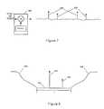
- FIG. 6illustrates an example embodiment of a synchronization code correlator 800 (shown in FIG. 7 ).
- a device 604 in cell 1receives an incoming communication from the cell 1 base station 606 , it compares the incoming data with SYNC 1 in correlator 800 . Essentially, the device scans the incoming data trying to correlate the data with the known synchronization code, in this case SYNC 1 .
- the devicematches the incoming data to SYNC 1 it generates a correlation peak 804 at the output. Multipath versions of the data will also generate correlation peaks 806 , although these peaks 806 are generally smaller than correlation peak 804 .
- the devicecan then use the correlation peaks to perform channel estimation, which allows the device to adjust for the multipath using an equalizer.
- correlator 800receives a data stream comprising SYNC 1 , it will generate correlation peaks 804 and 806 . If, on the other hand, the data stream comprises SYNC 2 , for example, then no peaks will be generated and the device will essentially ignore the incoming communication.
- a data stream that comprises SYNC 2will not create any correlation peaks, it can create noise in correlator 800 that can prevent detection of correlation peaks 804 and 806 .
- One way to minimize the noise created in correlator 800 by signals from adjacent cells 602is to configure system 600 so that each base station 606 transmits at the same time.
- the synchronization codescan preferably be generated in such a manner that only the synchronization codes 704 of adjacent cell data streams, e.g., streams 708 , 710 , and 712 , as opposed to packets 702 within those streams, will interfere with detection of the correct synchronization code 704 , e.g., SYNC 1 .
- the synchronization codescan then be further configured to eliminate or reduce the interference.
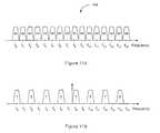
- the noise or interference caused by an incorrect synchronization codeis a function of the cross correlation of that synchronization code with respect to the correct code.
- the noise levelwill be virtually zero as illustrated in FIG. 8 by noise level 902 . Therefore, a preferred embodiment of system 600 uses synchronization codes that exhibit ideal cross correlation, i.e., zero.
- the ideal cross correlation of the synchronization codescovers a period l that is sufficient to allow accurate detection of multipath 906 as well as multipath correlation peaks 904 . This is important so that accurate channel estimation and equalization can take place.
- period lthe noise level 908 goes up, because the data in packets 702 is random and will exhibit low cross correlation with the synchronization code, e.g., SYNC 1 .
- the synchronization codee.g., SYNC 1 .
- period lis actually slightly longer then the multipath length in order to ensure that the multipath can be detected.
- each codemust have ideal, or zero, cross correlation with each of the other codes used in adjacent cells 602 . Therefore, in one example embodiment of a method for generating synchronization codes exhibiting the properties described above, the process begins by selecting a “perfect sequence” to be used as the basis for the codes.
- a perfect sequenceis one that when correlated with itself produces a number equal to the number of bits in the sequence. For example:
- the perfect sequence 1is again cyclically shifted by one bit, and again correlated with the original, then it will produce a “0”. In general, you can cyclically shift a perfect sequence by any number of bits up to its length and correlate the shifted sequence with the original to obtain a “0”.
- the first synchronization codeis preferably generated in one embodiment by repeating the sequence 4 times.
- yx (0) x (1) x (2) x (3) x (0) x (1) x (2) x (3) x (0) x (1) x (2) x (3) x (0) x (1) x (2) x (3).
- Equation (5)results in the desired shift as illustrated in FIG. 9 for each of synchronization codes 2 - 4 , relative to synchronization code 1 .
- the final step in generating each synchronization codeis to append the copies of the last M samples, where M is the length of the multipath, to the front of each code. This is done to make the convolution with the multipath cyclic and to allow easier detection of the multipath.
- communications from base station 1110comprise synchronization code SYNC 1 and communications from base station 1112 and 1114 comprise SYNC 2 and SYNC 3 respectively
- device 1108will effectively receive the sum of these three synchronization codes. This is because, as explained above, base stations 1110 , 1112 , and 1114 are configured to transmit at the same time. Also, the synchronization codes arrive at device 1108 at almost the same time because they are generated in accordance with the description above.
- the energy computed from the sum (SYNC 2 +SYNC 3 )is equal to the noise or interference seen by device 1108 . Since the purpose of correlating the synchronization code in device 1106 is to extract the energy in SYNC 1 , device 1108 also has the energy in the signal from base station 1110 , i.e., the energy represented by SYNC 1 . Therefore, device 1106 can use the energy of SYNC 1 and of (SYNC 2 +SYNC 3 ) to perform a signal-to-interference measurement for the communication channel over which it is communicating with base station 1110 . The result of the measurement is preferably a signal-to-interference ratio (SIR). The SIR measurement can then be communicated back to base station 1110 for purposes that will be discussed below.
- SIRsignal-to-interference ratio
- the SIR as determined by device 1108can be communicated back to base station 1110 for use in the assignment of channels 502 .
- the SIR for each sub-channel 502can be measured and communicated back to base station 1110 .
- sub-channels 502can be divided into groups and a SIR measurement for each group can be sent to base station 1110 .
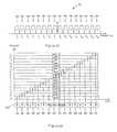
- FIG. 11Ashows a wideband communication channel 1200 segmented into sub-channels fo to f 15 .
- Sub-channels fo to f 15are then grouped into 8 groups G 1 to G 8 .
- device 1108 and base station 1110communicate over a channel such as channel 1200 .
- Sub-channels in the same groupare preferably separated by as many sub-channels as possible to ensure diversity.
- sub-channels within the same groupare 7 sub-channels apart, e.g., group G 1 comprises f 0 and f 8 .
- Device 1102reports a SIR measurement for each of the groups G 1 to G 8 . These SIR measurements are preferably compared with a threshold value to determine which sub-channels groups are useable by device 1108 . This comparison can occur in device 1108 or base station 1110 . If it occurs in device 1108 , then device 1108 can simply report to base station 1110 which sub-channels groups are useable by device 1108 .
- FIG. 11Billustrates the situation where two communication devices corresponding to User 1 and User 2 report SIR levels above the threshold for groups G 1 , G 3 , G 5 , and G 7 .
- Base station 1110preferably then assigns sub-channel groups to User 1 and User 2 based on the SIR reporting as illustrated in FIG. 11B .
- base station 1110also preferably assigns them based on the principles of frequency diversity. In FIG. 11B , therefore, User 1 and User 2 are alternately assigned every other “good” sub-channel.
- sub-channel assignmentcan be coordinated between cells, such as cells 1102 , 1104 , and 1106 in FIG. 10 , in order to prevent interference from adjacent cells.
- base station 1110can then be configured to assign only the odd groups, i.e., G 1 , G 3 , G 5 , etc., to device 1108 , while base station 1114 can be configured to assign the even groups to device 1118 .
- the two devices 1108 and 1118will then not interfere with each other due to the coordinated assignment of sub-channel groups.
- the sub-channelscan be divided by three.
- device 1108for example, can be assigned groups G 1 , G 4 , etc.
- device 1118can be assigned groups G 2 , G 5 , etc.
- device 1116can be assigned groups G 3 , G 6 , etc.
- the available bandwidth for these devicesi.e., devices near the edges of cells 1102 , 1104 , and 1106 , is reduced by a factor of 3, but this is still better than a CDMA system, for example.
- a communication devicesuch as device 1108 reports the SIR for all sub-channel groups G 1 to G 8 .
- the SIRs reportedare then compared, in step 1404 , to a threshold to determine if the SIR is sufficiently low for each group.
- device 1108can make the determination and simply report which groups are above or below the SIR threshold. If the SIR levels are good for each group, then base station 1110 can make each group available to device 1108 , in step 1406 .
- device 1108preferably measures the SIR level and updates base station 1110 in case the SIR as deteriorated. For example, device 1108 may move from near the center of cell 1102 toward the edge, where interference from an adjacent cell may affect the SIR for device 1108 .
- base station 1110can be preprogrammed to assign either the odd groups or the even groups only to device 1108 , which it will do in step 1408 .
- Device 1108then reports the SIR measurements for the odd or even groups it is assigned in step 1410 , and they are again compared to a SIR threshold in step 1412 .
- the poor SIR levelis due to the fact that device 1108 is operating at the edge of cell 1102 and is therefore being interfered with by a device such as device 1118 . But device 1108 will be interfering with device 1118 at the same time. Therefore, the assignment of odd or even groups in step 1408 preferably corresponds with the assignment of the opposite groups to device 1118 , by base station 1114 . Accordingly, when device 1108 reports the SIR measurements for whichever groups, odd or even, are assigned to it, the comparison in step 1410 should reveal that the SIR levels are now below the threshold level. Thus, base station 1110 makes the assigned groups available to device 1108 in step 1414 . Again, device 1108 preferably periodically updates the SIR measurements by returning to step 1402 .
- a third comparison step(not shown) can be implemented after step 1416 , to ensure that the groups assigned to device 1408 posses an adequate SIR level for proper operation. Moreover, if there are more adjacent cells, i.e., if it is possible for devices in a 4 th or even a 5 th adjacent cell to interfere with device 1108 , then the process of FIG. 13 would continue and the sub-channel groups would be divided even further to ensure adequate SIR levels on the sub-channels assigned to device 1108 .
- the SIR measurementscan be used in such a manner as to increase the data rate and therefore restore or even increase bandwidth.
- the transmitters and receivers used in base stations 1102 , 1104 , and 1106 , and in devices in communication therewith, e.g., devices 1108 , 1114 , and 1116 respectively,must be capable of dynamically changing the symbol mapping schemes used for some or all of the sub-channel.
- the symbol mapping schemecan be dynamically changed among BPSK, QPSK, 8PSK, 16QAM, 32QAM, etc.
- the base statione.g., base station 1110
- Device 1108must also change the symbol mapping scheme to correspond to that of the base stations. The change can be effected for all groups uniformly, or it can be effected for individual groups.
- the symbol mapping schemecan be changed on just the forward link, just the reverse link, or both, depending on the embodiment.
- the systems and methods described hereinprovide the ability to maintain higher available bandwidths with higher performance levels than conventional systems.
- the systems and methods describedthus far must be capable of implementation in a cost effect and convenient manner.
- the implementationmust include reconfigurability so that a single device can move between different types of communication systems and still maintain optimum performance in accordance with the systems and methods described herein.
- the following descriptionsdetail example high level embodiments of hardware implementations configured to operate in accordance with the systems and methods described herein in such a manner as to provide the capability just described above.
- transmitter 1500comprises a serial-to-parallel converter 1504 configured to receive a serial data stream 1502 comprising a data rate R.
- Serial-to-parallel converter 1504converts data stream 1502 into N parallel data streams 1504 , where N is the number of sub-channels 202 .
- Nis the number of sub-channels 202 .
- the data rate of each parallel data stream 1504is then R/N.
- Each data stream 1504is then sent to a scrambler, encoder, and interleaver block 1506 . Scrambling, encoding, and interleaving are common techniques implemented in many wireless communication transmitters and help to provide robust, secure communication. Examples of these techniques will be briefly explained for illustrative purposes.
- Encoding, or codingthe parallel bit streams 1504 can, for example, provide Forward Error Correction (FEC).
- FECForward Error Correction
- the purpose of FECis to improve the capacity of a communication channel by adding some carefully designed redundant information to the data being transmitted through the channel. The process of adding this redundant information is known as channel coding.
- Convolutional coding and block codingare the two major forms of channel coding. Convolutional codes operate on serial data, one or a few bits at a time. Block codes operate on relatively large (typically, up to a couple of hundred bytes) message blocks. There are a variety of useful convolutional and block codes, and a variety of algorithms for decoding the received coded information sequences to recover the original data.
- convolutional encoding or turbo coding with Viterbi decodingis a FEC technique that is particularly suited to a channel in which the transmitted signal is corrupted mainly by additive white gaussian noise (AWGN) or even a channel that simply experiences fading.
- AWGNadditive white gaussian noise
- Convolutional codesare usually described using two parameters: the code rate and the constraint length.
- the code rate, k/nis expressed as a ratio of the number of bits into the convolutional encoder (k) to the number of channel symbols (n) output by the convolutional encoder in a given encoder cycle.
- a common code rateis 1 ⁇ 2, which means that 2 symbols are produced for every 1-bit input into the coder.
- the constraint length parameter, Kdenotes the “length” of the convolutional encoder, i.e. how many k-bit stages are available to feed the combinatorial logic that produces the output symbols.
- Kdenotes the “length” of the convolutional encoder, i.e. how many k-bit stages are available to feed the combinatorial logic that produces the output symbols.
- Kis the “length” of the convolutional encoder, i.e. how many k-bit stages are available to feed the combinatorial logic that produces the output symbols.
- mis the parameter, which indicates how many
- each parallel data stream 1504is sent to symbol mappers 1508 .
- Symbol mappers 1508apply the requisite symbol mapping, e.g., BPSK, QPSK, etc., to each parallel data stream 1504 .
- Symbol mappers 1508are preferably programmable so that the modulation applied to parallel data streams can be changed, for example, in response to the SIR reported for each sub-channel 202 . It is also preferable, that each symbol mapper 1508 be separately programmable so that the optimum symbol mapping scheme for each sub-channel can be selected and applied to each parallel data stream 1504 .
- the transmitted signaloccupies the entire bandwidth B of communication channel 100 and comprises each of the discrete parallel data streams 1504 encoded onto their respective sub-channels 102 within bandwidth B. Encoding parallel data streams 1504 onto the appropriate sub-channels 102 requires that each parallel data stream 1504 be shifted in frequency by an appropriate offset. This is achieved in modulator 1510 .
- FIG. 16illustrates one example embodiment of a rate controller 1700 in accordance with the systems and methods described herein.
- Rate control 1700is used to control the data rate of each parallel data stream 1602 .
- the data rateis halved by repeating data streams d( 0 ) to d( 7 ), for example, producing streams a( 0 ) to a( 15 ) in which a( 0 ) is the same as a( 8 ), a( 1 ) is the same as a( 9 ), etc.
- FIG. 16also illustrates that the effect of repeating the data streams in this manner is to take the data streams that are encoded onto the first 8 sub-channels 1702 , and duplicate them on the next 8 sub-channels 1702 .
- 7 sub-channelsseparate sub-channels 1702 comprising the same, or duplicate, data streams.
- the other sub-channels 1702 carrying the same datawill likely not be effected, i.e., there is frequency diversity between the duplicate data streams. So by sacrificing data rate, in this case half the data rate, more robust transmission is achieved.
- the robustness provided by duplicating the data streams d( 0 ) to d( 7 )can be further enhanced by applying scrambling to the duplicated data streams via scramblers 1708 .
- the data ratecan be reduced by more than half, e.g., by four or more.
- the data ratecan also be reduced by an amount other than half.
- information from n data streamis encoded onto m sub-channels, where m>n.
- information from one data streamcan be encoded on a first sub-channel
- information from a second data streamcan be encoded on a second data channel
- the sum or difference of the two data streamscan be encoded on a third channel.
- proper scalingwill need to be applied to the power in the third channel.
- the power in the third channelcan be twice the power in the first two.
- rate controller 1700is programmable so that the data rate can be changed responsive to certain operational factors. For example, if the SIR reported for sub-channels 1702 is low, then rate controller 1700 can be programmed to provide more robust transmission via repetition to ensure that no data is lost due to interference. Additionally, different types of wireless communication system, e.g., indoor, outdoor, line-of-sight, may require varying degrees of robustness. Thus, rate controller 1700 can be adjusted to provide the minimum required robustness for the particular type of communication system. This type of programmability not only ensures robust communication, it can also be used to allow a single device to move between communication systems and maintain superior performance.
- FIG. 17illustrates an alternative example embodiment of a rate controller 1800 in accordance with the systems and methods described.
- rate controller 1800the data rate is increased instead of decreased. This is accomplished using serial-to-parallel converters 1802 to convert each data streams d( 0 ) to d( 15 ), for example, into two data streams.
- Delay circuits 1804then delay one of the two data streams generated by each serial-to-parallel converter 1802 by 1 ⁇ 2 a symbol.
- data streams d( 0 ) to d( 15 )are transformed into data streams a( 0 ) to a( 31 ).
- the data streams generated by a particular serial-to-parallel converter 1802 and associate delay circuit 1804must then be summed and encoded onto the appropriate sub-channel. For example, data streams a( 0 ) and a( 1 ) must be summed and encoded onto the first sub-channel.
- the data streamsare summed subsequent to each data stream being pulsed shaped by a filter
- rate controller 1604is preferably programmable so that the data rate can be increased, as in rate controller 1800 , or decreased, as in rate controller 1700 , as required by a particular type of wireless communication system, or as required by the communication channel conditions or sub-channel conditions.
- filters 1612are also preferably programmable so that they can be configured to apply pulse shapping to data streams a( 0 ) to a( 31 ), for example, and then sum the appropriate streams to generate the appropriate number of parallel data streams to send to frequency shifter 1614 .
- the advantage of increasing the data rate in the manner illustrated in FIG. 17is that higher symbol mapping rates can essentially be achieved, without changing the symbol mapping used in symbol mappers 1508 .
- the summed streamsare shifted in frequency so that they reside in the appropriate sub-channel. But because the number of bits per each symbol has been doubled, the symbol mapping rate has been doubled.
- a 4QAM symbol mappingcan be converted to a 16QAM symbol mapping, even if the SIR is too high for 16QAM symbol mapping to otherwise be applied.
- programming rate controller 1800 to increase the data rate in the manner illustrated in FIG. 17can increase the symbol mapping even when channel conditions would otherwise not allow it, which in turn can allow a communication device to maintain adequate or even superior performance regardless of the type of communication system.
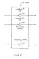
- FIG. 18illustrates one example embodiment of a frequency encoder 1900 in accordance with the systems and methods described herein. Similar to rate encoding, frequency encoding is preferably used to provide increased communication robustness.
- frequency encoder 1900the sum or difference of multiple data streams are encoded onto each sub-channel. This is accomplished using adders 1902 to sum data streams d( 0 ) to d( 7 ) with data streams d( 8 ) to d( 15 ), respectively, while adders 1904 subtract data streams d( 0 ) to d( 7 ) from data streams d( 8 ) to d( 15 ), respectively, as shown.
- data streams a( 0 ) to a( 15 ) generated by adders 1902 and 1904comprise information related to more than one data streams d( 0 ) to d( 15 ).
- a( 0 )comprises the sum of d( 0 ) and d( 8 ), i.e., d( 0 )+d( 8 ), while a( 8 ) comprises d( 8 ) ⁇ d( 0 ). Therefore, if either a( 0 ) or a( 8 ) is not received due to fading, for example, then both of data streams d( 0 ) and d( 8 ) can still be retrieved from data stream a( 8 ).
- the relationship between data stream d( 0 ) to d( 15 ) and a( 0 ) to a( 15 )is a matrix relationship.
- the receiverknows the correct matrix to apply, it can recover the sums and differences of d( 0 ) to d( 15 ) from a( 0 ) to a( 15 ).
- frequency encoder 1900is programmable, so that it can be enabled and disabled in order to provided robustness when required.
- adders 1902 and 1904are programmable also so that different matrices can be applied to d( 0 ) to d( 15 ).
- FIG. 19illustrates an example embodiment of a TDM/FDM block 2000 configured to perform TDM on a data stream.
- TDM/FDM block 2000is provided to illustrate the logical components that can be included in a TDM/FDM block configured to perform TDM on a data stream. Depending on the actual implementation, some of the logical components may or may not be included.
- TDM/FDM block 2000comprises a sub-block repeater 2002 , a sub-block scrambler 2004 , a sub-block terminator 2006 , a sub-block repeater 2008 , and a sync inserter 2010 .
- Sub-block repeater 2002is configured to receive a sub-block of data, such as block 2012 comprising bits a( 0 ) to a( 3 ) for example. Sub-block repeater is then configured to repeat block 2012 to provide repetition, which in turn leads to more robust communication. Thus, sub-block repeater 2002 generates block 2014 , which comprises 2 blocks 2012 . Sub-block scrambler 2004 is then configured to receive block 2014 and to scramble it, thus generating block 2016 .
- One method of scramblingcan be to invert half of block 2014 as illustrated in block 2016 . But other scrambling methods can also be implemented depending on the embodiment.
- Sub-block terminator 2006takes block 2016 generated by sub-block scrambler 2004 and adds a termination block 2034 to the front of block 2016 to form block 2018 .
- Termination block 2034ensures that each block can be processed independently in the receiver. Without termination block 2034 , some blocks may be delayed due to multipath, for example, and they would therefore overlap part of the next block of data. But by including termination block 2034 , the delayed block can be prevented from overlapping any of the actual data in the next block.
- Termination block 2034can be a cyclic prefix termination 2036 .
- a cyclic prefix termination 2036simply repeats the last few symbols of block 2018 .
- termination block 2034can comprise a sequence of symbols that are known to both the transmitter and receiver. The selection of what type of block termination 2034 to use can impact what type of equalizer is used in the receiver. Therefore, receiver complexity and choice of equalizers must be considered when determining what type of termination block 2034 to use in TDM/FDM block 2000 .
- TDM/FDM block 2000can include a sub-block repeater 2008 configured to perform a second block repetition step in which block 2018 is repeated to form block 2020 .
- sub-block repeatercan be configured to perform a second block scrambling step as well.
- TDM/FDM block 2000comprises a sync inserter 210 configured to periodically insert an appropriate synchronization code 2032 after a predetermined number of blocks 2020 and/or to insert known symbols into each block. The purpose of synchronization code 2032 is discussed in section 3.
- FIG. 20illustrates an example embodiment of a TDM/FDM block 2100 configured for FDM, which comprises sub-block repeater 2102 , sub-block scrambler 2104 , block coder 2106 , sub-block transformer 2108 , sub-block terminator 2110 , and sync inserter 2112 .
- sub-block repeater 2102repeats block 2114 and generates block 2116 .
- Sub-block scramblerthen scrambles block 2116 , generating block 2118 .
- Sub-block coder 2106takes block 2118 and codes it, generating block 2120 . Coding block correlates the data symbols together and generates symbols b.
- Sub-block transformer 2108then performs a transformation on block 2120 , generating block 2122 .
- the transformationis an IFFT of block 2120 , which allows for more efficient equalizers to be used in the receiver.
- sub-block terminator 2110terminates block 2122 , generating block 2124 and sync inserter 2112 periodically inserts a synchronization code 2126 after a certain number of blocks 2124 and/or insert known symbols into each block.
- sub-block terminator 2110only uses cyclic prefix termination as described above. Again this allows for more efficient receiver designs.
- TDM/FDM block 2100is provided to illustrate the logical components that can be included in a TDM/FDM block configured to perform FDM on a data stream. Depending on the actual implementation, some of the logical components may or may not be included. Moreover, TDM/FDM block 2000 and 2100 are preferably programmable so that the appropriate logical components can be included as required by a particular implementation. This allows a device that incorporates one of blocks 2000 or 2100 to move between different systems with different requirements. Further, it is preferable that TDM/FDM block 1608 in FIG. 15 be programmable so that it can be programmed to perform TDM, such as described in conjunction with block 2000 , or FDM, such as described in conjunction with block 2100 , as required by a particular communication system.
- the parallel data streamsare preferably passed to interpolators 1610 .
- the parallel data streamsare passed to filters 1612 , which apply the pulse shapping described in conjunction with the roll-off factor of equation (2) in section 1. Then the parallel data streams are sent to frequency shifter 1614 , which is configured to shift each parallel data stream by the frequency offset associated with the sub-channel to which the particular parallel data stream is associated.
- FIG. 21illustrates an example embodiment of a frequency shifter 2200 in accordance with the systems and methods described herein.
- frequency shifter 2200comprises multipliers 2202 configured to multiply each parallel data stream by the appropriate exponential to achieve the required frequency shift.
- frequency shifter 1614 in FIG. 5is programmable so that various channel/sub-channel configurations can be accommodated for various different systems.
- an IFFT blockcan replace shifter 1614 and filtering can be done after the IFFT block. This type of implementation can be more efficient depending on the implementation.
- each sub-channelmay be assigned to one user, or each sub-channel may carry a data stream intended for different users.
- the assignment of sub-channelsis described in section 3b. Regardless of how the sub-channels are assigned, however, each user will receive the entire bandwidth, comprising all the sub-channels, but will only decode those sub-channels assigned to the user.
- FIG. 22illustrates an example embodiment of a receiver 2300 that can be configured in accordance with the present invention.
- Receiver 2300comprises an antenna 2302 configured to receive a message transmitted by a transmitter, such as transmitter 1500 .
- antenna 2302is configured to receive a wide band message comprising the entire bandwidth B of a wide band channel that is divided into sub-channels of bandwidth b.
- the wide band messagecomprises a plurality of messages each encoded onto each of a corresponding sub-channel. All of the sub-channels may or may not be assigned to a device that includes receiver 2300 ; Therefore, receiver 2300 may or may not be required to decode all of the sub-channels.
- Radio receiver 2304After the message is received by antenna 2300 , it is sent to radio receiver 2304 , which is configured to remove the carrier associated with the wide band communication channel and extract a baseband signal comprising the data stream transmitted by the transmitter. The baseband signal is then sent to correlator 2306 and demodulator 2308 .
- Correlator 2306is configured to correlated with a synchronization code inserted in the data stream as described in section 3. It is also preferably configured to perform SIR and multipath estimations as described in section 3(b).
- Demodulator 2308is configured to extract the parallel data streams from each sub-channel assigned to the device comprising receiver 2300 and to generate a single data stream therefrom.
- FIG. 23illustrates an example embodiment of a demodulator 2400 in accordance with the systems and methods described herein.
- Demodulator 2402comprises a frequency shifter 2402 , which is configured to apply a frequency offset to the baseband data stream so that parallel data streams comprising the baseband data stream can be independently processed in receiver 2400 .
- the output of frequency shifter 2402is a plurality of parallel data streams, which are then preferably filtered by filters 2404 .
- Filters 2404apply a filter to each parallel data stream that corresponds to the pulse shape applied in the transmitter, e.g., transmitter 1500 .
- an IFFT blockcan replace shifter 1614 and filtering can be done after the IFFT block. This type of implementation can be more efficient depending on the implementation.
- receiver 2400preferably includes decimators 2406 configured to decimate the data rate of the parallel bit streams. Sampling at higher rates helps to ensure accurate recreation of the data. But the higher the data rate, the larger and more complex equalizer 2408 becomes. Thus, the sampling rate, and therefore the number of samples, can be reduced by decimators 2406 to an adequate level that allows for a smaller and less costly equalizer 2408 .
- Equalizer 2408is configured to reduce the effects of multipath in receiver 2300 . Its operation will be discussed more fully below.
- the parallel data streamsare sent to de-scrambler, decoder, and de-interleaver 2410 , which perform the opposite operations of scrambler, encoder, and interleaver 1506 so as to reproduce the original data generated in the transmitter.
- the parallel data streamsare then sent to parallel to serial converter 2412 , which generates a single serial data stream from the parallel data streams.
- Equalizer 2408uses the multipath estimates provided by correlator 2306 to equalize the effects of multipath in receiver 2300 .
- equalizer 2408comprises Single-In Single-Out (SISO) equalizers operating on each parallel data stream in demodulator 2400 .
- SISOSingle-In Single-Out
- each SISO equalizer comprising equalizer 2408receives a single input and generates a single equalized output.
- each equalizercan be a Multiple-In Multiple-Out (MIMO) or a Multiple-In Single-Out (MISO) equalizer.
- MIMOMultiple-In Multiple-Out
- MISOMultiple-In Single-Out
- each equalizers comprising equalizer 2408need to equalize more than one sub-channel.
- equalizer 2408can then generate a single output corresponding to d( 1 ) or d( 8 ) (MISO) or it can generate both d( 1 ) and d( 8 ) (MIMO).
- Equalizer 2408can also be a time domain equalizer (TDE) or a frequency domain equalizer (FDE) depending on the embodiment.
- equalizer 2408is a TDE if the modulator in the transmitter performs TDM on the parallel data streams, and a FDE if the modulator performs FDM.
- equalizer 2408can be an FDE even if TDM is used in the transmitter. Therefore, the preferred equalizer type should be taken into consideration when deciding what type of block termination to use in the transmitter. Because of power requirements, it is often preferable to use FDM on the forward link and TDM on the reverse link in a wireless communication system.
- demodulator 2400are preferably programmable, so that a single device can operate in a plurality of different systems and still maintain superior performance, which is a primary advantage of the systems and methods described herein. Accordingly, the above discussion provides systems and methods for implementing a channel access protocol that allows the transmitter and receiver hardware to be reprogrammed slightly depending on the communication system.
- a devicewhen a device moves from one system to another, it preferably reconfigures the hardware, i.e. transmitter and receiver, as required and switches to a protocol stack corresponding to the new system.
- An important part of reconfiguring the receiveris reconfiguring, or programming, the equalizer because multipath is a main problem for each type of system.
- the multipathvaries depending on the type of system, which previously has meant that a different equalizer is required for different types of communication systems.
- the channel access protocol described in the preceding sectionsallows for equalizers to be used that need only be reconfigured slightly for operation in various systems.
- FIG. 24illustrates an example embodiment of a receiver 2500 illustrating one way to configure equalizers 2506 in accordance with the systems and methods described herein.
- one way to configure equalizers 2506is to simply include one equalizer per channel (for the systems and methods described herein, a channel is the equivalent of a sub-channel as described above).
- a correlatorsuch as correlator 2306 ( FIG. 22 ) can then provide equalizers 2506 with an estimate of the number, amplitude, and phase of any multipaths present, up to some maximum number. This is also known as the Channel Impulse Response (CIR).
- CIRChannel Impulse Response
- the maximum number of multipathsis determined based on design criteria for a particular implementation. The more multipaths included in the CIR the more path diversity the receiver has and the more robust communication in the system will be. Path diversity is discussed a little more fully below.
- equalizers 2506are preferably provided directly to equalizers 2506 from the correlator (not shown). If such a correlator configuration is used, then equalizers 2506 can be run at a slow rate, but the overall equalization process is relatively fast. For systems with a relatively small number of channels, such a configuration is therefore preferable. The problem, however, is that there is large variances in the number of channels used in different types of communication systems. For example, an outdoor system can have has many as 256 channels. This would require 256 equalizers 2506 , which would make the receiver design too complex and costly. Thus, for systems with a lot of channels, the configuration illustrated in FIG. 25 is preferable.
- each equalizer 2506multiple channels share each equalizer 2506 .
- each equalizercan be shared by 4 channels, e.g., Ch 1 -Ch 4 , Ch 5 -Ch 8 , etc., as illustrated in FIG. 25 .
- receiver 2500preferably comprises a memory 2502 configured to store information arriving on each channel.
- Memory 2502is preferably divided into sub-sections 2504 , which are each configured to store information for a particular subset of channels. Information for each channel in each subset is then alternately sent to the appropriate equalizer 2506 , which equalizes the information based on the CIR provided for that channel. In this case, each equalizer must run much faster than it would if there was simply one equalizer per channel. For example, equalizers 2506 would need to run 4 or more times as fast in order to effectively equalize 4 channels as opposed to 1. In addition, extra memory 2502 is required to buffer the channel information. But overall, the complexity of receiver 2500 is reduced, because there are fewer equalizers. This should also lower the overall cost to implement receiver 2500 .
- memory 2502 and the number of channels that are sent to a particular equalizeris programmable.
- receiver 2500can be reconfigured for the most optimum operation for a given system.
- receiver 2500were moved from an outdoor system to an indoor system with fewer channels, then receiver 2500 can preferably be reconfigured so that there are fewer, even as few as 1, channel per equalizer.
- the rate at which equalizers 2506 are runis also preferably programmable such that equalizers 2506 can be run at the optimum rate for the number of channels being equalized.
- each equalizer 2506is equalizing multiple channels, then the CIR for those multiple paths must alternately be provided to each equalizer 2506 .
- a memory(not shown) is also included to buffer the CIR information for each channel. The appropriate CIR information is then sent to each equalizer from the CIR memory (not shown) when the corresponding channel information is being equalized.
- the CIR memory(not shown) is also preferably programmable to ensure optimum operation regardless of what type of system receiver 2500 is operating in.
- the number of paths used by equalizers 2506must account for the delay spread d s in the system.
- the communication channelcan comprise a bandwidth of 125 Mega Hertz (MHz), e.g., the channel can extend from 5.725 GHz to 5.85 GHz. If the channel is divided into 512 sub-channels with a roll-off factor r of 0.125, then each subchannel will have a bandwidth of approximately 215 kilohertz (KHz), which provides approximately a 4.6 microsecond symbol duration.
- KHzkilohertz
- the number of paths used by equalizers 2504can be set to a maximum of 5.
- a first path P 1 at zero microsecondsthere would be a first path P 1 at zero microseconds, a second path P 2 at 4.6 microseconds, a third path P 3 at 9.2 microseconds, a fourth path P 4 at 13.8 microseconds, and fifth path P 5 at 18.4 microseconds, which is close to the delay spread d s .
- a sixth pathcan be included so as to completely cover the delay spread d s ; however, 20 microseconds is the worst case.
- a delay spread d s of 3 microsecondsis a more typical value. In most instances, therefore, the delay spread d s will actually be shorter and an extra path is not needed.
- fewer sub-channelscan be used, thus providing a larger symbol duration, instead of using an extra path. But again, this would typically not be needed.
- equalizers 2506are preferably configurable so that they can be reconfigured for various communication systems.
- the number of paths usedmust be sufficient regardless of the type of communication system. But this is also dependent on the number of sub-channels used. If, for example, receiver 2500 went from operating in the above described outdoor system to an indoor system, where the delay spread d s is on the order of 1 microsecond, then receiver 2500 can preferably be reconfigured for 32 sub-channels and 5 paths. Assuming the same overall bandwidth of 125 MHz, the bandwidth of each sub-channel is approximately 4 MHz and the symbol duration is approximately 250 nanoseconds.
- the delay spread dsshould be covered for the indoor environment.
- the 1 microsecond delay spread d sis worst case so the 1 microsecond delay spread d s provided in the above example will often be more than is actually required. This is preferable, however, for indoor systems, because it can allow operation to extend outside of the inside environment, e.g., just outside the building in which the inside environment operates. For campus style environments, where a user is likely to be traveling between buildings, this can be advantageous.
- FIG. 25illustrates an example embodiment of a wireless communication device in accordance with the systems and methods described herein.
- Device 2600is, for example, a portable communication device configured for operation in a plurality of indoor and outdoor communication systems.
- device 2600comprises an antenna 2602 for transmitting and receiving wireless communication signals over a wireless communication channel 2618 .
- Duplexor 2604or switch, can be included so that transmitter 2606 and receiver 2608 can both use antenna 2602 , while being isolated from each other.
- Duplexors, or switches used for this purposeare well known and will not be explained herein.
- Transmitter 2606is a configurable transmitter configured to implement the channel access protocol described above.
- transmitter 2606is capable of transmitting and encoding a wideband communication signal comprising a plurality of sub-channels.
- transmitter 2606is configured such that the various sub-components that comprise transmitter 2606 can be reconfigured, or programmed, as described in section 5.
- receiver 2608is configured to implement the channel access protocol described above and is, therefore, also configured such that the various sub-components comprising receiver 2608 can be reconfigured, or reprogrammed, as described in section 6.
- Transmitter 2606 and receiver 2608are interfaced with processor 2610 , which can comprise various processing, controller, and/or Digital Signal Processing (DSP) circuits.
- processor 2610controls the operation of device 2600 including encoding signals to be transmitted by transmitter 2606 and decoding signals received by receiver 2608 .
- Device 2610can also include memory 2612 , which can be configured to store operating instructions, e.g., firmware/software, used by processor 2610 to control the operation of device 2600 .
- Processor 2610is also preferably configured to reprogram transmitter 2606 and receiver 2608 via control interfaces 2614 and 2616 , respectively, as required by the wireless communication system in which device 2600 is operating.
- device 2600can be configured to periodically ascertain the availability is a preferred communication system. If the system is detected, then processor 2610 can be configured to load the corresponding operating instruction from memory 2612 and reconfigure transmitter 2606 and receiver 2608 for operation in the preferred system.
- device 2600it may preferable for device 2600 to switch to an indoor wireless LAN if it is available. So device 2600 may be operating in a wireless WAN where no wireless LAN is available, while periodically searching for the availability of an appropriate wireless LAN. Once the wireless LAN is detected, processor 2610 will load the operating instructions, e.g., the appropriate protocol stack, for the wireless LAN environment and will reprogram transmitter 2606 and receiver 2608 accordingly. In this manner, device 2600 can move from one type of communication system to another, while maintaining superior performance.
- operating instructionse.g., the appropriate protocol stack
- a base stationconfigured in accordance with the systems and methods herein will operate in a similar manner as device 2600 ; however, because the base station does not move from one type of system to another, there is generally no need to configure processor 2610 to reconfigure transmitter 2606 and receiver 2608 for operation in accordance with the operating instruction for a different type of system. But processor 2610 can still be configured to reconfigure, or reprogram the sub-components of transmitter 2606 and/or receiver 2608 as required by the operating conditions within the system as reported by communication devices in communication with the base station. Moreover, such a base station can be configured in accordance with the systems and methods described herein to implement more than one mode of operation. In which case, controller 2610 can be configured to reprogram transmitter 2606 and receiver 2608 to implement the appropriate mode of operation.
- FIGS. 26-49additional embodiments of the present invention are illustrated.
- the embodiments described belowmay contain some of the features and functionality as described above.
- UWBultra-wideband
- UWBimpulse type ultra-wideband
- UWB pulsesmay be transmitted without modulation onto a sine wave, or a sinusoidal carrier, in contrast with conventional carrier wave communication technology.
- This type of UWBgenerally requires neither an assigned frequency nor a power amplifier.
- IEEE 802.11ais a wireless local area network (LAN) protocol, which transmits a sinusoidal radio frequency signal at a 5 GHz center frequency, with a radio frequency spread of about 5 MHz.
- LANwireless local area network
- a carrier waveis an electromagnetic wave of a specified frequency and amplitude that is emitted by a radio transmitter in order to carry information.
- the 802.11 protocolis an example of a carrier wave communication technology.
- the carrier wavecomprises a substantially continuous sinusoidal waveform having a specific narrow radio frequency (5 MHz) that has a duration that may range from seconds to minutes.
- an ultra-wideband (UWB) pulsemay have a 2.0 GHz center frequency, with a frequency spread of approximately 4 GHz, as shown in FIG. 27 , which illustrates two typical UWB pulses.
- FIG. 27illustrates that the shorter the UWB pulse in time, the broader the spread of its frequency spectrum. This is because bandwidth is inversely proportional to the time duration of the pulse.
- a 600-picosecond UWB pulsecan have about a 1.8 GHz center frequency, with a frequency spread of approximately 1.6 GHz and a 300-picosecond UWB pulse can have about a 3 GHz center frequency, with a frequency spread of approximately 3.3 GHz.
- UWB pulsesgenerally do not operate within a specific frequency, as shown in FIG. 26 .
- Either of the pulses shown in FIG. 27may be frequency shifted, for example, by using heterodyning, to have essentially the same bandwidth but centered at any desired frequency. And because UWB pulses are spread across an extremely wide frequency range, UWB communication systems allow communications at very high data rates, such as 100 megabits per second or greater.
- UWBultra-wideband
- Fractional bandwidthis defined as 2 times the difference between the high and low 10 dB cutoff frequencies divided by the sum of the high and low 10 dB cutoff frequencies. Specifically, the fractional bandwidth equation is:
- f his the high 10 dB cutoff frequency
- f lis the low 10 dB cutoff frequency
- fractional bandwidthis the percentage of a signal's center frequency that the signal occupies.
- FIG. 28illustrates the ultra-wideband emission limits for indoor systems mandated by the April 22 Report and Order.
- the Report and Orderconstrains UWB communications to the frequency spectrum between 3.1 GHz and 10.6 GHz, with intentional emissions to not exceed ⁇ 41.3 dBm/MHz.
- the report and orderalso established emission limits for hand held UWB systems, vehicular radar systems, medical imaging systems, surveillance systems, through-wall imaging systems, ground penetrating radar and other UWB systems. It will be appreciated that the invention described herein may be employed indoors, and/or outdoors, and may be fixed, and/or mobile, and may employ either a wireless or wire media for a communication channel.
- UWB pulsesmay be transmitted at relatively low power density (milliwatts per megahertz).
- an alternative UWB communication systemlocated outside the United States, may transmit at a higher power density.
- UWB pulsesmay be transmitted between 30 dBm to ⁇ 50 dBm.
- UWB pulsestransmitted through many wire media will not interfere with wireless radio frequency transmissions. Therefore, the power (sampled at a single frequency) of UWB pulses transmitted though wire media may range from about +30 dBm to about ⁇ 140 dBm.
- the FCC's April 22 Report and Orderdoes not apply to communications through wire media.
- UWB communication methodsmay transmit UWB pulses that occupy 500 MHz bands within the 7.5 GHz FCC allocation (from 3.1 GHz to 10.6 GHz).
- UWB pulseshave about a 2-nanosecond duration, which corresponds to about a 500 MHz bandwidth.
- the center frequency of the UWB pulsescan be varied to place them wherever desired within the 7.5 GHz allocation.
- IFFTInverse Fast Fourier Transform
- the resultant UWB pulse, or signalis approximately 506 MHz wide, and has approximately 242-nanosecond duration. It meets the FCC rules for UWB communications because it is an aggregation of many relatively narrow band carriers rather than because of the duration of each pulse.
- OFDMOrthogonal Frequency Division Multiplexing
- UWB pulse durationsmay vary from 2 nanoseconds, which occupies about 500 MHz, to about 133 picoseconds, which occupies about 7.5 GHz of bandwidth. That is, a single UWB pulse may occupy substantially all of the entire allocation for communications (from 3.1 GHz to 10.6 GHz).
- Yet another UWB communication method being evaluated by the IEEE standards committeescomprises transmitting a sequence of pulses that may be approximately 0.7 nanoseconds or less in duration, and at a chipping rate of approximately 1.4 giga pulses per second.
- the pulsesare modulated using a Direct-Sequence modulation technique, and is called DS-UWB. Operation in two bands is contemplated, with one band is centered near 4 GHz with a 1.4 GHz wide signal, while the second band is centered near 8 GHz, with a 2.8 GHz wide UWB signal. Operation may occur at either or both of the UWB bands. Data rates between about 28 Megabits/second to as much as 1,320 Megabits/second are contemplated.
- Another method of UWB communicationscomprises transmitting a modulated continuous carrier wave where the frequency occupied by the transmitted signal occupies more than the required 20 percent fractional bandwidth.
- the continuous carrier wavemay be modulated in a time period that creates the frequency band occupancy. For example, if a 4 GHz carrier is modulated using binary phase shift keying (BPSK) with data time periods of 750 picoseconds, the resultant signal may occupy 1.3 GHz of bandwidth around a center frequency of 4 GHz. In this example, the fractional bandwidth is approximately 32.5%. This signal would be considered UWB under the FCC regulation discussed above.
- BPSKbinary phase shift keying
- UWBultra-wideband
- data 5110 of interestmay be provided to data interface 5040 .
- a number of data interfaces 5040are known in the art and can be used to practice the current invention.
- the data interface 5040may include an industry standard such as a Universal Serial Bus (USB) standard interface, an IEEE 1394 standard interface, a Peripheral Component Interconnect standard (PCI), a Peripheral Component Interconnect Express (PCI-Express) standard, a MILSPEC-1760 standard, and a MILSPEC-1553 standard.
- PCIPeripheral Component Interconnect standard
- PCI-ExpressPeripheral Component Interconnect Express
- MILSPEC-1760MILSPEC-1760
- MILSPEC-1553MILSPEC-1553
- Non-industry standard interfacesmay also be employed and the present invention is not limited with respect to the type of data interface 5040 used.
- Data 5110is sent from data interface 5040 to the Medium Access Controller (MAC) 5030 .
- the MAC 5030performs a number of functions on the data
- a data frame 5100comprises a medium access control header 5120 , a data section 5110 , a source ID, a destination ID, a rate field 5130 , and in some embodiments may include a Cyclical Redundancy Check 5115 (CRC) appended to the end of the frame 5100 .
- CRCCyclical Redundancy Check
- the data frames 5100are then sent to a baseband processor 5020 , which performs a number of functions (described below) and produces baseband frame 5050 , illustrated in FIG. 33 .
- a “frame” as defined herein, whether a data frame 5100 , a baseband frame 5050 , or another type of “frame,”may include many different constructions and arrangements.
- a “frame”usually consists of a representation of the original data to be transmitted (generally comprising a specified number of bits, or binary digits), together with other bits that may be used for error detection or control.
- a “frame”may also include routing information, such as a source address, a destination address, and other information.
- a “frame”may be of different lengths, and contain variable amounts of data. It will be appreciated that the construction of baseband frame 5050 and data frame 5100 may vary without exceeding the scope of the present invention.
- CRCcyclic redundancy check
- FCSFrame Check Sequence
- FIG. 33illustrates the baseband frame 5050 produced by the baseband processor 5020 .
- the baseband frame 5050comprises a physical layer header 5180 , the medium access control header 5120 and a number of data packets 5200 .
- Each data packet 5200includes a code block 5190 , which is used by the receiver 5220 (shown in FIG. 34 ) for synchronization of the packet 5200 .
- the baseband frame 5050may include the FCS used to decode the CRC as described above.
- Physical layer header 5180may comprise a number of synchronization code blocks 5190 which are used by the receiver 5220 to synchronize its timing reference to the timing reference of the transmitter 5210 .
- synchronizationis used to obtain a fixed relationship among corresponding significant instants of two or more signals.
- synchronizationalso known as frame synchronization, frame alignment, or framing
- a receiverto lock onto an incoming frame so that it may receive the data contained in the frame.
- the receiversynchronizes its time base, or reference to the time base of the transmitter.
- a “frame synchronization pattern,” generally comprising a recurring pattern of bits,is transmitted that enables the receiver to align its clock, or time reference with the transmitter's time reference (i.e., synchronization). Repetition of the bit pattern helps ensure that the receiver will have an opportunity to “lock” in on the timing of the incoming signal.
- the synchronization code blocks 5190are comprised of 256 bit Golay codes. In another embodiment, one or more of the Golay codes may be inverse Golay codes. It will be appreciated that other types of synchronization codes, comprised of other bit sizes, may be employed by the present invention.
- One feature of the present inventionis that upon reception of the synchronization sequence, the receiver may adjust its time base, its frequency base, and a setting of an automatic gain control amplifier (not shown).
- the baseband frame 5050is then sent from the baseband processor 5020 to modulator 5420 , which contains a digital circuit 5080 and local oscillator 5090 .
- Modulator 5420performs modulation of the baseband frame 5050 , which includes representations of individual data bits, into a transmission signal 5070 . That is, the baseband processor 5020 outputs a signal comprised of high and low signal values, each having a time duration, or time base T 0 , shown in FIG. 30 , which represent the data comprising the baseband frame 5050 .
- the local oscillator 5090generates a clock signal 5060 at a time base T 1 , illustrated in FIG. 30 .
- local oscillator 5090may be a voltage controlled oscillator.
- the signal values representing the baseband frame 5050are at a time base T 0 .
- the digital circuit 5080uses the clock signal 5060 , the digital circuit 5080 modulates, or changes the signal values representing the baseband frame 5050 .
- the type of modulationis phase modulation.
- the local oscillator 5090may generate a clock signal 5060 with a time base T 1 of 250 picoseconds.
- the digital circuit 5080produces a transmission signal 5070 that would be centered at 4 Giga-Hertz (GHz), which is the inverse of 250 picoseconds.
- the inverse of the baseband frame 5050 signal valuescontrols the amount of occupied bandwidth around the center frequency of the transmission signal 5070 .
- the transmission signalwould occupy 1.3 GHz of bandwidth, around a 4 GHz center frequency.
- the bandwidthi.e., amount of radio frequency spectrum
- the fractional bandwidth of this signalcalculated by the formula given above, would be approximately 33.25%.
- this transmission signal 5070would be considered UWB under the current FCC definition because its fractional bandwidth exceeds 20%.
- the clock signal 5060 time base T 1may be approximately 133 picoseconds and the time base T 0 of the baseband frame 5050 signal values may be approximately 146 picoseconds.
- the transmission signal 5070in this case would have a center frequency of 6.85 GHz and the signal would occupy 7.5 GHz of bandwidth around the center frequency.
- the transmission signal 5070would occupy the entire available UWB spectrum from 3.1 GHz to 10.6 GHz. It would have a fractional bandwidth of approximately 110% and would be considered UWB.
- a clock signal time base T 1 of approximately 2 nanoseconds with a time base T 0 of the baseband frame 5050 signal values of approximately 5300 picosecondsyields a transmission signal 5070 that occupies 500 MHz of bandwidth located around a center frequency of 3.35 GHz.
- the fractional bandwidth of this exemplary transmission signal 5070is only approximately 15%. While this signal does not meet the current UWB definition in terms of fractional bandwidth, it is still considered UWB since it occupies the required minimum of 500 MHz of bandwidth.
- a clock signal 5060 time base T 1may be approximately 100 picoseconds and the time base T 0 of the baseband frame 5050 signal values may be 200 picoseconds.
- the transmission signal 5070would occupy 10 GHz of bandwidth around a center frequency of 5 GHz.
- the bandwidth occupied by this transmission signal 5070would extend from Direct Current at zero Hertz up to 10 GHz.
- This signalwould occupy a fractional bandwidth of approximately 200%.
- this signalwould be a UWB signal but under the current FCC regulations would not be allowed for wireless transmission as a portion of the signal would be below the FCC mandated 3.1 GHz frequency boundary.
- One feature of the present inventionis that by generating a clock signal at the desired center frequency used for transmission, the present invention does not need to employ a mixer to position the signal at the transmission frequency.
- the present inventioncan generate a signal anywhere within (or outside of) the FCC mandated UWB radio frequency band by using a high-speed clock signal at the desired frequency. This feature reduces the overall cost and complexity of the device.
- the high-speed clockis a 10.6 Giga-Hertz (GHz) clock, but it will be appreciated that other clocks, such as 4 GHz, 8 GHz, 12 GHz, and others may be employed by the present invention.
- FIGS. 32 a , 32 b , and 32 cSeveral embodiments of digital circuit 5080 are illustrated in FIGS. 32 a , 32 b , and 32 c .
- One feature of the digital circuits 5080 discussed belowis that they directly generate the transmission signal, without mixing, or up-converting the signal to the radio frequency used for transmission.
- the locally generated clock 5060 and the baseband frame 5050 signal valuesare the inputs to an “exclusive or” function or gate.
- an “exclusive or” (XOR) gateperforms the following function:
- InputInput: Transmission Signal values 5050 Clock 5060 Signal 5070 0 0 0 0 0 1 1 1 0 1 1 1 0
- the “high” values in clock 5060will cause the transmission signal 5070 to be “high.”
- the “low” valueswill result in a “low” in the transmission signal 5070 .
- the transmission signal 5070mirrors the clock 5060 .
- the “high” values in clock 5060result in “low” values in the transmission signal 5070 .
- the “low” clock 5060 valuesresult in a “high” transmission signal 5070 .
- the inverse of clock 5060becomes the transmission signal 5070 . In this manner the signal values 5050 modulate the phase of the transmission signal 5070 .
- signal values 5050 and clock 5060are inputs into an “and” gate. Additionally, the inverse of clock 5060 and signal values 5050 are inputs into another “and” gate. Combiner 5160 may then passively combine the outputs of the two “and” gates, or functions. As is known in the art, and shown in TABLE II, an “and” gate performs the following logical function:
- InputInput: Transmission Signal values 5050 Clock 5060 Signal 5070 0 0 0 0 1 0 1 0 0 1 1 1 1
- the output of the “and” gate 5150 afollows the clock 5060 .
- the output of “and” gate 5150is “low”.
- the inverse of signal values 5050 and the inverse of clock 5060are inputs to “and” gate 5150 b .
- the transmission signal 5070becomes the inverse of the clock 5060 .
- the two outputs from “and” gates 5150 a and 5150 bmay then be combined by combiner 5160 to produce transmission signal 5070 .
- the phase of the clock 5060is modulated by the signal values 5050 to become transmission signal 5070 .
- the transmission signal 5070 generated by the embodiment in FIG. 32 ahas an inverse phase relationship to the transmission signal generated by the embodiment shown in FIG. 32 b .
- Either circuitmay be modified by one with skill in the art to produce the other signal.
- FIG. 32 cYet another embodiment of digital circuit 5080 is illustrated in FIG. 32 c .
- This embodimentcan produce either of the transmission signals 5070 shown in FIG. 30 and FIG. 38 , by reversing the inputs of clock 5060 and its inverse.
- a 2:1 multiplexer 5170is used to generate a transmission signal 5070 .
- the clock 5060 and its inverseare connected to the multiplexer 5170 .
- the signal values 5050 from the baseband frameare connected to the control S 0 .
- the signal value 5050has a low value
- the signal present at input 0 , clock 5060is passed to the output transmission signal 5070 .
- the signal value 5050has a “high” value
- the signal present at input 1 , inverse clock 5060is passed to the output.
- the clock 5060is phase modulated by signal values 5050 to produce transmission signal 5070 .
- chipping codewhere the time period of the code is referred to as a chip, or chip duration.
- the chipping codeusually has a shorter duration time period than the signal value used to represent the data. Stated otherwise, the chip duration is usually shorter than the data symbol, or signal value duration.
- the resulting signalis a signal that occupies the bandwith of the chipping signal and carries the data signal. This bandwidth can be expressed as the inverse of the chip duration.
- the ratio of chips per data symbolis commonly referred to as the spreading factor.
- the process of multiplying the data signal by the chipping codeis generally referred to as spreading the signal.
- the process in a receiver of recovering the data signal from a spread signalmay be referred to as de-spreading.
- the spread signalis then multiplied by a carrier wave to place the signal at the radio frequency used for transmission.
- orthogonal codesare used to enable a multiple access scheme, where multiple users can communicate simultaneously.
- the spreading factorintroduces generally unwanted overhead into a communications system.
- a data symbolcould be transmitted without spreading.
- a spreading factor of 1is employed, implying the data has not been spread.
- the same data symbolwould be 256 times larger than the same symbol using a spreading factor of 1. For example, if a spreading factor of 1 is used to send 1 bit of data, then 1 bit is transmitted. If a spreading factor of 256 is employed, then 256 bits are used to transmit 1 bit of data. So, as the spreading factor increases, the amount of data transmitted decreases.
- One advantage of spreading the signal with a chipping codeis that a receiver may use the entire chipping code to recover the signal. This process is commonly referred to as processing gain. Processing gain, expressed in dB, assists the receiver in detection of the signal, which increases communication reliability.
- processing gainexpressed in dB
- Another advantage of spreading with a chipping codeis that when orthogonal codes are employed in different networks, the users in one network will not intercept the signals of the users in other networks.
- the transmission signal 5070is spread by a chipping code or code block 5190 , shown in FIG. 33 .
- portions of the transmission signal 5070have a different spreading factor.
- the physical layer header 5180may have a spreading factor of 256 where the medium access control header 5120 may have a spreading factor of 64.
- the packets 5200may have a spreading factor that is dynamically controlled by the medium access controller 5030 that inserts the chosen spreading factor in rate field 5130 of the medium access control header 5120 .
- the spreading factormay be dynamically adjusted to accommodate a changing communication environment. For example, if the distance the transmission signal 5070 must travel increases, the spreading factor may also increase, so that a receiver can recover the signal. Or, in a communication environment that is conducive to multipath, the spreading factor may also be increased. Alternatively, when the communication environment is favorable to communications, the spreading factor may be reduced, thereby increasing the rate at which data is transmitted.
- FIG. 35which illustrates some functions performed by baseband processor 5020 .
- Frames 5100are received from the medium access controller 5030 by the baseband processor 5020 .
- the rate field 5130 in the medium access control header 5120is evaluated to determine the data rate for the packets 5200 .
- FEC encoder 5300applies a FEC (forward error correction, discussed below) encoding level to the data frame 5100 .
- the baseband processor 5020uses the rate field 5130 to set the FEC encoding and/or the spreading factor. It will be appreciated that different spreading factors, and/or FEC encoding levels may be employed by the present invention.
- Encoding for Forward Error Correctionis a process by which redundancy is added too the data to be transmitted. With the additional redundancy the receiver may then attempt to detect and correct errors in the received data.
- An initial step in a FEC algorithmis to encode the data with additional bits.
- FEC encoding algorithmsOf significant importance in communications are block codes and convolutional codes. Both types of encoding algorithms transform the original data set into a coded sequence of larger size. This increased size can yield a decrease in performance of information throughput for a particular data rate but may enable a more robust communication link.
- convolutional encodingthe coded sequence depends not only on the current data bits being encoded but also on one or more previous data bits.
- a distinct block of data bitsis encoded by a code.
- the FEC encoding levelotherwise known as the coding efficiency is a ratio of the original data to the encoded data.
- a FEC encoding level of 1 ⁇ 2implies a 50% overhead or redundancy has been added to the data (50% more bits).
- a 3 ⁇ 4 FEC encoding levelincludes a 25% overhead.
- a FEC encoding level of 1means that no additional bits have been added to the data.
- Other encoding ratesare known in the art of communications and may be used.
- Those encoding levelsinclude 1 ⁇ 8 th rate encoding, 1 ⁇ 4 rate encoding, 3 ⁇ 8 th rate encoding 1 ⁇ 2 rate encoding, 5 ⁇ 8 th rate encoding, 7 ⁇ 8 th rate encoding, and 3 ⁇ 4 rate encoding.
- Interleavingis a process by which the order of the bits to be transmitted is changed.
- One purpose of interleaving bits or a block of bitsis to improve a communications systems' noise immunity. For example, if bits from different portions of the data frame 5100 are interleaved, or mixed into a packet 5200 and that packet is corrupted by noise, or other factors during transmission, the impact of the corrupted packet is distributed across multiple areas of the data. This reduces the number of potential errors in any contiguous block of data, thereby increasing the probability that a receiver can correct the corrupted data.
- the datais forwarded to scrambler 5320 .
- Scrambling the datareduces the probability of having long strings of similar data bits. Long strings of similar data bits may alter the distribution of transmitted power, known as the Power Spectral Density (PSD), within the spectrum. In many cases it is advantageous to have the effect of the data on the PSD be minimal. In those instances the effect of data should be random, or white, within the spectrum.
- PSDPower Spectral Density
- the datais then sent to the spreader 5430 .
- a spreading factoris applied to the data.
- the spreading factormay change based on the contents of the rate field 5130 .
- the spread datais then sent to the packetizer 5340 where it is broken into discrete blocks appropriate for each packet 5200 .
- the synchronization generator 5350generates synchronization code blocks 5190 for each packet.
- the header generator 5330generates and forms the physical layer header 5180 .
- the physical layer header 5180is then appended onto the medium access control header 5120 .
- a completed baseband frame 5050is then forwarded to the modulator 5420 . It will be appreciated that the data processing order described above may be changed, and that other processing steps may be added or subtracted.
- an RF signalis received from the communication media (wire or wireless) by the RF front end 5010 .
- the RF front end 5010sends the received signal to an analog-to-digital converter (ADC) 5230 .
- ADC 5230may be a 1-bit ADC, a 2-bit ADC, a 3-bit ADC, a 4-bit ADC, a 5-bit ADC, a 6-bit ADC, a 7-bit ADC or an 8-bit ADC.
- Other bit densities for ADCsare known in the art of communications and may be used to practice the invention.
- ADC 5230is a 1-bit sigma delta ADC.
- ADC 5230samples the RF signal and creates a serial data signal.
- the serial data signalis sent to baseband processor 5020 which converts, or reassembles the packets 5200 from the serial data signal into data frames 5110 which are sent to the medium access controller 5030 .
- the medium access controllerconverts the data frames 5110 into data 5100 , which is sent to a data interface 5040 .
- Data interface 5040may comprise a number of different data interfaces as described above.
- RF front end 5010may comprise a number of components including one or more antennas for communications in a wireless media, or coupling circuits for communication using wire media.
- the baseband processor 5020may comprise a poly-phase filter 5240 , a de-spreader 5250 , a channel impulse response detector 5260 , a channel matched filter 5410 , a de-scrambler 5270 , a de-interleaver 5280 and a FEC decoder 5290 .
- RF front end 5010may comprise two or more receive antennas (not shown).
- the receive antennasare separated by a physical distance from each other that approximates at least one wavelength of the center frequency of the signal the receiver is designed to receive.
- the wavelengthis calculated by dividing the speed of light by the frequency. For example, a communication signal with a 4 GHz center frequency has a wavelength of approximately 7.5 cm.
- the receiverhas a better chance of determining which received signal is a direct path signal and which is a multi-path signal.
- the multiple receive antennasprovide additional energy collection which may be used to detect the communication signal.
- FIGS. 37 and 38Two embodiments of poly-phase filter 5240 are illustrated in FIGS. 37 and 38 .
- One function of the poly-phase filter 5240is to down-convert the serial data signal into two lower frequency signals.
- the two signalsare commonly referred to as In-phase (I) and Quadrature (Q).
- This conversionis accomplished by multiplying the serial data signal by a complex sinusoid. Since the serial data signal is discrete (having been sampled) the complex sinusoid is discrete samples of a sinusoid. The real and imaginary parts of a complex sinusoid may be calculated and stored in a look-up table 5400 .
- the serial data signalis split into two parallel signals by serial to parallel converter 5360 .
- Serial to parallel converter 5360merely outputs alternate samples onto each output.
- Multipliers 5370multiply the samples by real and imaginary coefficients that represent the complex sinusoid.
- the resultant product signalsare filtered by filters 5380 .
- filters 5380are low-pass finite impulse response (FIR) filters. FIR filters are known in the art of signal processing and will not be discussed herein. It will be appreciated that other types of filters may be employed by the present invention.
- Decimators 5390then decimate the filtered signals. Decimation is a process by which a number of samples are discarded. In the embodiment illustrated in FIG. 38 , decimation occurs prior to filtering the signals.
- the poly-phase filtersends the resultant signal to the de-spreader 5250 .
- the process of de-spreading the signalinvolves correlating the signal with a synchronization code block. If the received signal contains the same, or an inverse of the synchronization code block, the de-spreader finds a strong correlation, either positive or negative. The synchronization code block may then be removed and replaced by a value. The de-spreader 5250 then sends the signal to the channel impulse response detector 5260 and the channel matched filter 5410 .
- a wireless communication channelis generally characterized as a multipath fading channel, which includes multipath signals that cause intersymbol interference.
- a conventional matched filterincludes an estimated model of the communication channel, which is used to aid the matched filter in obtaining the strongest possible signal.
- the estimated modeldoes not accurately reflect the actual communication channel, the signal may be poorly recovered leading to a poor signal-to-noise ratio (SNR).
- SNRsignal-to-noise ratio
- a degraded SNRmay result in an increased bit-error-rate (BER), or may reduce the effective range of the communication system.
- a channel impulse response detector 5260is employed to provide a real-time analysis of the actual communication channel to the channel matched filter 5410 .
- the channel impulse response detector 5260measures the communication channel impulse response by “listening” for correlations at a number of time periods. Generally, the impulse response is detected from the time period in which strong correlations are found with the codes contained within the physical layer header 5180 and code blocks 5190 (in packets 5200 ).
- codesare known in the art, but exemplary codes may include Golay, Walsh and perfect code sequences.
- the de-spreader 5250may correlate on delayed or multipath copies of the intended signal. Because of different propagation path lengths, multipath copies may show up at the receiver 5220 at a different time period than the intended signal. In this situation, the channel impulse response detector 5260 provides the time of arrival and strength of the multipath copies to the channel matched filter 5410 . The channel matched filter 5410 may then sum the received energy within the multipath copies to provide a stronger signal strength. In this way, the actual communication channel characteristics are determined and used to obtain the strongest possible signal.
- the channel matched filter 5410may also include an equalization capability, or function.
- the goal of equalizationis to provide as accurate an estimate of the original data as possible.
- This “estimated” datacan then be forwarded to subsequent processing blocks, such as the forward error correction (FEC) decoder 5290 .
- FECforward error correction
- One function of the FECis to detect and correct errors in the estimated data. If errors are detected, various remedial measures are performed. These measures will be discussed below in connection with the FEC decoder 5290 .
- the channel matched filter 5410includes a simplified decision feedback equalization (DFE) function.
- DFEdecision feedback equalization
- the multipath copies of previous signalsmay arrive at a time when receiver 5220 is processing a current signal.
- the received signalmay be made up of the intended signal and a number of multipath copies of previous signals.
- the data signalmay comprise the sum of 2 or more autocorrelation functions.
- the data signalmay comprise the sum of 64 autocorrelation functions, or alternatively, the data signal may comprise the sum of 32, 128 or other sums of autocorrelation functions.
- a 1 * and A 2 *are the complex conjugates of A 1 and A 2 .
- the last four terms in equation (8)are what is known as Inter Symbol Interference (ISI) or Inter Chip Interference (ICI).
- ISIInter Symbol Interference
- ICIInter Chip Interference
- the first termis the data. So, in this exaple, a current data sample, or decision, actually depends on the current sample as well as two past samples and two future samples. Obtaining the two past samples should not drive the complexity of the equalizer; however, obtaining two future samples does increase complexity.
- equalizer of the present inventionthe two future samples are ignored.
- a “hard” estimationis employed. This is in contrast with most conventional equalizers, which often depend on “soft” decisions.
- the output from the hard decisionis used to obtain the past two samples, which are multiplied by the associated amplitude factors A 1 and A 2 and combined.
- the A 1 and A 2 and other amplitude factorsare represented by g L,L .
- the coefficients g L,Lare determined from the channel estimations.
- the amplitude factorsare supplied to the channel matched filter 5410 from the channel impulse response detector 5260 during processing of the physical layer header 5180 and during the processing of each packet 5200 .
- DFEThe output of the DFE can then be passed onward for further processing.
- a general implementation of DFEis an iterative process that significantly reduces the ISI or ICI. Further, the DFE may include a parity check, or the like, in order to detect errors. If there are no errors, then there is no reason to feedback the data and perform the iteration.
- the channel matched filter 5410then sends the signal to de-scrambler 5270 .
- de-scrambler 5270de-scrambles the data.
- the de-scramblersends the de-scrambled data to the de-interleaver 5280 .
- de-interleaver 280de-interleaves the data.
- FEC decoder 5290detects and corrects errors in the recovered data 5110 .
- a number of decoding algorithmsare known in the art and may be used to practice the invention. In one embodiment the FEC decoding algorithm is a low density parity check (LDPC) algorithm.
- LDPClow density parity check
- error controlcomprises two methods, error detection and error correction.
- error detection algorithmsthe received data is merely checked for error. If errors are found, the transmitter may be notified and the data may be retransmitted.
- error correction algorithmsthe receiver attempts to correct detected errors.
- FECForward Error Correction
- extra bitsare transmitted with the data that can be used by the receiver to detect and correct errors in the data that was received.
- the receivercan then ask that the data be re-sent if too many errors are detected.
- an FEC encoder 3202adds bits to an input data stream 3204 to create an output data stream 3206 that necessarily requires a higher data rate due to the added bits.
- FEC encoder 3202is a 1 ⁇ 2 rate FEC encoder, which means that for every input bit d n , FEC encoder 3202 adds a bit that can be used to detect errors when data stream 3206 is decoded.
- rate encoderssuch as full rate, or 3 ⁇ 4 rate encoders may be employed by the present invention.
- data rate of output 3206is twice that of input 3204 .
- Data stream 3206can then be modulated and transmitted to a receiver.
- an FEC decoder 3208can be used to remove the extra bits and detect errors in the original data.
- FEC decoder 3208should match FEC encoder 3202 , i.e., FEC decoder 3208 should be a 1 ⁇ 2 rate FEC decoder, in the above example.
- FIG. 42depicts a portion of a transmitter chain 3300 .
- a data stream 3302with a data rate (R) is first split into a plurality of parallel data streams 3306 in serial to parallel converter 3304 , each with a lower data rate (R/n) where n is the number of parallel data streams 3306 .
- the parallel data streams 3306can then be encoded using a plurality of FEC encoders.
- each of FEC encoders 3308 and 3310can, depending on the implementation, encode half as much data and operate at a lower speed than required in a conventional system. More generally, FEC encoders 3308 and 3310 can be configured to assist each other with FEC encoding and reduce the overall load on each FEC encoder in the system. This, of course, requires some coordination, or message passing, between the two FEC encoders.
- the outputs of FEC encoders 3308 and 3310can then, for example, be passed through parallel to serial converters 3312 and 3314 and combined via combiner 3316 into a single data stream with FEC encoding.
- the single data streamcan then be optional filtered and/or pulse shaped before being modulated an transmitted, e.g., via optional block 3318 ,
- a code wordis generated from an input data word by adding parity bits to the data word as illustrated in FIG. 43 .
- FEC encoder 3402referred to as a Low Density Parity Check (LDPC) encoder, takes data word 3404 and generates output code word 3406 .
- LDPCLow Density Parity Check
- the data word and code wordare illustrated in matrix form.
- the data wordis a matrix comprising p m +d k rows and 1 column.
- LDPCis an error correction algorithm where the data to be sent is encoded by a generator matrix and decoded by a parity matrix. Derivation of the two matrices is seen below in equation 12.
- the FEC encoder 3402a “K” length block of data K ⁇ 1 is multiplied by the generator matrix G N ⁇ K which produces a “N” length block N ⁇ 1 where N>K. The additional length is attributed to the overhead described above.
- the parity matrixmay represent a connection of two types of nodes in the decoder. The locations of 1's in the matrix represent the connection of the two types of nodes.
- the decoding of the block on receiptis usually an iterative process by which the first type of node may calculate information related to the probability of the bit under consideration being a 1 or a 0. In some cases this probability may be expressed as a “log likelihood ratio” or mathematically:
- y ) Pr ⁇ ( c i1
- lnis the natural log
- the numeratoris the probability that the bit c i is a zero
- the denominatoris the probability it is a 1.
- This informationis passed to the other type of nodes specified by the parity check matrix, who perform a similar calculation based on the information received from each of the first type of node.
- the second type of nodethen sends its calculation to each of the first type of nodes it is connected to. This process continues until it is stopped or reaches some figure of merit in its result. Since each node is connected to a number of nodes of the other type, each iteration improves the probability calculation at each node.
- H Pis configured as a dual diagonal matrix with M rows and M columns. Dual diagonal matrices are well known and will not be described here; however and exemplary one is illustrated by the following:
- H P[ 1 1 0 0 ⁇ 0 0 1 1 0 ⁇ 0 0 0 1 1 ⁇ 0 0 0 0 1 ⁇ 1 0 0 0 ⁇ 0 1 ] ( 17 )
- H Dcan, depending on the embodiment, be formed from a matrix of matrices. In one embodiment, this matrix of matrices is itself block cyclic. For example, in one embodiment, 4 matrices A, B, C and D can be used as in the following:
- H D[ A B C D B C D A C D A B D A B C ] ( 18 )
- each of the matrices A, B, C, and Dwill have k/4 rows and k/4 columns.
- an encoder and decoder configured in accordance with the systems and methods described hereincan be optimized for a dual diagonal H P and a block cyclic H D , an explained below.
- Many methodscan be used to generate matrices A, B, C, and D consistent with the systems and methods described herein.
- each of matrices A, B, C, and Dcan then be generated from this identity matrix L
- a permutation vectorin this example of length 4, can then be used to generate A.
- other methods for generating matrices A, B, C, and Dcan be used consistently with the systems and methods described herein.
- the matrix Acan, e.g., have the following form, once an appropriate permutation vector is used to modify identity matrix I:
- a permutation vectorcan be used to shift the positions of the 1's in identity matrix I.
- a single permutation matrixcan be required.
- the other matrices B, C, and Dcan be generated by shifting matrix A.
- each subsequent matrices B, C, and Dis generated by shifting the previous matrix, starting with A, by 90°.
- Bwould be as follows:
- each rowhas only a single 1.
- Equation (27)can be implemented effectively if can be generated efficiently.
- H Dwas partitioned in 4 s, therefore should also be partitioned by 4 as illustrated in the following:
- the above equationcan be implemented efficiently, for example, using a circuit such as the example circuit illustrated in FIG. 45 .
- the circuit of FIG. 45uses a bank of cyclic shift registers 3606 to implement .
- the outputs of shift registers 3606can then be passed to a plurality XORs 3602 as shown.
- XORs 3602collect the appropriate outputs from shift registers 3606 in order to generate the U terms.
- each cyclic shift registerwill only have one 1, due to the fact that A, B, C, and D have only one 1 in each row, the outputs of cyclic shift registers 3606 can be rearranged and fixed so that, e.g., the first outputs of each go to the first XOR 3602 , the second outputs go to the second XOR 3602 , etc. Accordingly, efficient fixed connections 3608 can be used to reduce the complexity of LDPC 3402 . The U terms can then be registered and fed to XOR 3502 as illustrated.
- the cyclic shift registers 3606can be shifted k/4 times. On each clock cycle, k/4 of the solution would be generated, such that it takes k/4 cycles to get the entire solution. This can result in a highly parallel encoder, such as that illustrated in FIG. 36 , for high-speed operation. The result can also be a low cost encoder, because the hardware can be reduced to 1 ⁇ 4th that required by conventional circuits through the reuse of the components.
- the job of the decoderis then to extract from the signal represented by equation 32.
- thiscan be accomplished by making soft decisions as to the value of and combining it with hard decisions related to the sign such that can then be accurately determined.
- the soft decisionscan be based on a multilevel possibility. For example, if 4 bits are used in 2's complement, then you can have up to 16 levels. In one embodiment, the levels can, for example, be from ⁇ 8 to 7. Alternatively, using offset 2's complement, the levels can be from ⁇ 7.5 to 7.5. An advantage of the later is that the levels are not biased, e.g., toward the negative. An advantage of the former, however, is that it includes the level 0. Of course, any level scheme can be used as long as it allows for accurate determinations of .
- the levelscan be used to determine the probabilities of the value of and ultimately . For example, if the level determined for is 7 or 7.5, then the decoder can be configured to see this as a high probability that the value is 1. If the level is ⁇ 8 or ⁇ 7.5, then this can be seen as a high probability that the value is ⁇ 1.
- Parity check equationscan then be generated from the following:
- a parity node processor 3702can be used to implement equation 34, as illustrated by the example embodiment depicted in FIG. 46 . Message passing algorithms can be used to allow each such node 3702 to make final estimations.
- FIG. 48is a diagram illustrating and example embodiment in which a plurality of parity node processors 3702 are configured in accordance with the systems and methods described herein.
- each node 3702receives information as to what the values x 0 , x 1 , . . . x N are believed to be.
- a given node 3702can then process this information and produce estimates as to what the node believes the output of the other nodes should be and feed this information back in such a manner that the subsequent input to the other nodes is modified. It should be noted, therefore, that in such an embodiment, a node does not produce information to be fedback to its own input related to what it believes its own output should be.
- information for each bitis provided to node 3702 , which processes the information and produces information related to what it determines each bit should be.
- edges (E)Each output edge is fedback to the relevant input bit.
- the node processors 3702will, therefore, comprise storage to store the information being fed to it and processed as required. As a result, both storage and routing overheads can become excessive.
- the edge produce by node S 0is not fed back to bit x 0 .
- FIG. 49is a diagram illustrating an example decoder 4000 that can be configured to reduce storage and routing overhead in accordance with one embodiment of the systems and methods described herein.
- the basic premise behind decoder 4000is that all the edges produced form parity node processor 4002 can be added and then the last edge for each node, produced by that node, can be subtracted out.
- a given rowcan be updated for all edges and then shifted in shift registers 4004 .
- the appropriate edgecan then be subtracted out for each row using the data provided from registers 4014 , as opposed to doing each row, storing the result and updating it with information from other nodes.
- each shift register 4008gets information from only two nodes 3702 , e.g., via registers 4010 and 4012 .
- One feature of the present inventionis that it may be used to increase the bandwidth of wireless networks or networks that employ wired media.
- the present inventioncan be used to transmit ultra-wideband signals across any type of wired media.
- the wired mediacan include optical fiber ribbon, fiber optic cable, single mode fiber optic cable, multi-mode fiber optic cable, plenum wire, PVC wire, and coaxial cable.
- the wired mediacan include twisted-pair wiring, whether shielded or unshielded.
- Twisted-pair wiremay consist of “pairs” of color-coded wires. Common sizes of twisted-pair wire are 2 pair, 3 pair, 4 pair, 25 pair, 50 pair and 100 pair. Twisted-pair wire is commonly used for telephone and computer networks. It comes in ratings ranging from category 1 to category 7. Twisted-pair wiring also is available unshielded. That is, the wiring does not have a foil or other type of wrapping around the group of conductors within the jacket. This type of wiring is most commonly used for wiring for voice and data networks.
- the foregoing list of wired mediais meant to be exemplary, and not exclusive.
- the present inventioncan provide additional bandwidth to enable the transmission of large amounts of data over an existing wired media network, whether the wired media network is a Internet service provider, cable television provider, or a computer network located in a business or university.
- the additional bandwidthcan allow consumers to receive the high speed Internet access, interactive video and other features that are bandwidth intensive.
- the present inventionmay be employed in any type of network, be it wireless, wire, or a mix of wire media and wireless components. That is, a network may use both wire media, such as coaxial cable, and wireless devices, such as satellites, or cellular antennas.
- a networkis a group of points or nodes connected by communication paths. The communication paths may use wires or they may be wireless.
- a network as defined hereincan interconnect with other networks and contain sub-networks.
- a network as defined hereincan be characterized in terms of a spatial distance, for example, such as a local area network (LAN), a personal area network (PAN), a metropolitan area network (MAN), a wide area network (WAN), and a wireless personal area network (WPAN), among others.
- LANlocal area network
- PANpersonal area network
- MANmetropolitan area network
- WANwide area network
- WPANwireless personal area network
- a network as defined hereincan also be characterized by the type of data transmission technology used by the network, such as, for example, a Transmission Control Protocol/Internet Protocol (TCP/IP) network, a Systems Network Architecture network, among others.
- TCP/IPTransmission Control Protocol/Internet Protocol
- a network as defined hereincan also be characterized by whether it carries voice, data, or both kinds of signals.
- a network as defined hereinmay also be characterized by users of the network, such as, for example, users of a public switched telephone network (PSTN) or other type of public network, and private networks (such as within a single room or home), among others.
- PSTNpublic switched telephone network
- a network as defined hereincan also be characterized by the usual nature of its connections, for example, a dial-up network, a switched network, a dedicated network, and a non-switched network, among others.
- a network as defined hereincan also be characterized by the types of physical links that it employs, for example, optical fiber, coaxial cable, a mix of both, unshielded twisted pair, and shielded twisted pair, among others.
- the present inventionmay be employed in any type of wireless network, such as a wireless PAN, LAN, MAN, or WAN.
- the present inventionmay be employed in wire media, as the present invention dramatically increases the bandwidth of conventional networks that employ wire media, yet it can be inexpensively deployed without extensive modification to the existing wire media network.
- One feature of the present inventionis that it has a data rate and quality of service high enough to support multiple video streams.
- one embodiment of the present inventionmay provide a communication channel having a data rate of 1.3 gigabits per second. This high data rate is particularly useful in hand held security devices.
- Such systemscan provide dramatically improved national security.
- current airport security systemsinvolve large, stationary equipment that scans luggage and passengers. However, an individual may pass through a security checkpoint without being scanned or checked for identification. At most commercial airports it may be exceedingly difficult to locate the individual using current methods and equipment. In most cases the security personnel are relying on a verbal description of the individual, which may be inaccurate. Under current regulatory guidelines the terminal must be closed, emptied of passengers and manually searched.
- security camera access points throughout the airportmay transmit one or more channels of streaming video directly to video viewers carried by security personnel, thereby allowing the search to be conducted in a more efficient manner.
- the data rates of conventional wireless communication systemscannot support multiple video streams, and therefore cannot provide the features and functionality of the present invention.
Landscapes
- Engineering & Computer Science (AREA)
- Computer Networks & Wireless Communication (AREA)
- Signal Processing (AREA)
- Mobile Radio Communication Systems (AREA)
- Digital Transmission Methods That Use Modulated Carrier Waves (AREA)
Abstract
Description
T=1/B=1/100 megahertz (MHZ)=10 nanoseconds (ns). (1)
b=(1+r)/T; (2)
- Where r=the roll-off factor; and
- T=the symbol duration.
- Where r=the roll-off factor; and
B=N(1+r)/T, (3)
or
B=M/T; (4)
Where
M=(1+r)N. (5)
y=1 1−1 1 1 1−1 1 1 1−1 1 1 1−1 1.
y=x(0)x(1)x(2)x(3)x(0)x(1)x(2)x(3)x(0)x(1)x(2)x(3)x(0)x(1)x(2)x(3).
y=x(0)x(1) . . .x(L)x(0)x(1) . . .x(L)x(0)x(1) . . .x(L)x(0)x(1) . . .x(L)
zr(m)=y(m)*exp(j*2*π*r*m/(n*L)), (5)
- for r=1 to L (# of sequences) and m=0 to 4*L−1 (time); and
- where:
- zr(m)=each subsequent sequence;
- y(m)=the first sequence; and
- n=the number of times the sequence is repeated.
x=SYNC1+SYNC2+SYNC3. (6)
x−SYNC1=SYNC2+SYNC3. (7)
| TABLE I | ||
| Output: | ||
| Input: | Input: | Transmission |
| Signal values 5050 | ||
| 0 | 0 | 0 |
| 0 | 1 | 1 |
| 1 | 0 | 1 |
| 1 | 1 | 0 |
| TABLE II | ||
| Output: | ||
| Input: | Input: | Transmission |
| Signal values 5050 | ||
| 0 | 0 | 0 |
| 0 | 1 | 0 |
| 1 | 0 | 0 |
| 1 | 1 | 1 |
| TABLE | |||
| Rate Field | |||
| 5130 | FEC Encoding | Spreading | |
| Level | Factor | ||
| 0 | 1 | 1 |
| 1 | ¾ | 1 |
| 2 | ½ | 1 |
| 3 | 1 | 2 |
| 4 | ¾ | 2 |
| 5 | ½ | 2 |
| 6 | 1 | 4 |
| 7 | ¾ | 4 |
| 8 | ½ | 4 |
| 9 | 1 | 8 |
| 10 | ¾ | 8 |
| 11 | ½ | 8 |
| 12 | 1 | 16 |
| 13 | ¾ | 16 |
| 14 | ½ | 16 |
| 15 | 1 | 32 |
| 16 | ¾ | 32 |
| 17 | ½ | 32 |
| 18 | 1 | 64 |
| 19 | ¾ | 64 |
| 20 | ½ | 64 |
| 21 | 1 | 128 |
| 22 | ¾ | 128 |
| 23 | ½ | 128 |
| 24 | 1 | 256 |
| 25 | ¾ | 256 |
| 26 | ½ | 256 |
Zn=(A0×dn)+(A1×d2)+(A2×dn−1)+(A1*×dn+1)+(A2*×dn+2) (8)
Z0=(A0×d0)+(A1×d1)+(A2×d2) (9)
Which becomes:
Z0−[(A1×d1)+(A2×d2)]=(A0×d0) (10)


where ln is the natural log, the numerator is the probability that the bit ciis a zero and the denominator is the probability it is a 1. This information is passed to the other type of nodes specified by the parity check matrix, who perform a similar calculation based on the information received from each of the first type of node. The second type of node then sends its calculation to each of the first type of nodes it is connected to. This process continues until it is stopped or reaches some figure of merit in its result. Since each node is connected to a number of nodes of the other type, each iteration improves the probability calculation at each node.
- where:
- GN×Kis the Generator Matrix
- N=M+k;
- R=k/N;
- if R=½, then M=k.
- where:
G=[I;P] (12)
- where:
- I=the identity matrix; and
- P=the parity matrix.
- where:
HM×N*

HM×N=[HPM×MHDM×K] (14)

1+1=0;
1−1=0;
1+0=1;
0+1=1;
0+1=1; and
0−1=−1=1. (22)
(HP*
(HP*
(HP*
(HD*

Accordingly:
(HP*
p0−u0;
p1+p0=u1;
p2+p1=u2;
p3+p2=u3;
p4+p3=u4;
p5+p4=u5; (29)
pn=un−pn−1 (30)

S0=x0+x1+x2+x3+x4+x5 (34)
x0+E1+1(s1→x0)+E1+1(S2→x0)+ . . . (35)
Claims (7)
Priority Applications (6)
| Application Number | Priority Date | Filing Date | Title |
|---|---|---|---|
| US11/055,525US8045935B2 (en) | 2001-12-06 | 2005-02-09 | High data rate transmitter and receiver |
| CNA2006800043782ACN101427475A (en) | 2005-02-09 | 2006-01-26 | High data rate transmitter and receiver |
| EP06719709AEP1847023A4 (en) | 2005-02-09 | 2006-01-26 | High data rate transmitter and receiver |
| PCT/US2006/002973WO2006086168A2 (en) | 2005-02-09 | 2006-01-26 | High data rate transmitter and receiver |
| US13/317,224US8744389B2 (en) | 2001-12-06 | 2011-10-12 | High data rate transmitter and receiver |
| US13/317,177US8532586B2 (en) | 2001-12-06 | 2011-10-12 | High data rate transmitter and receiver |
Applications Claiming Priority (2)
| Application Number | Priority Date | Filing Date | Title |
|---|---|---|---|
| US10/010,601US7289494B2 (en) | 2001-12-06 | 2001-12-06 | Systems and methods for wireless communication over a wide bandwidth channel using a plurality of sub-channels |
| US11/055,525US8045935B2 (en) | 2001-12-06 | 2005-02-09 | High data rate transmitter and receiver |
Related Parent Applications (1)
| Application Number | Title | Priority Date | Filing Date |
|---|---|---|---|
| US10/010,601Continuation-In-PartUS7289494B2 (en) | 2001-12-06 | 2001-12-06 | Systems and methods for wireless communication over a wide bandwidth channel using a plurality of sub-channels |
Related Child Applications (2)
| Application Number | Title | Priority Date | Filing Date |
|---|---|---|---|
| US13/317,224DivisionUS8744389B2 (en) | 2001-12-06 | 2011-10-12 | High data rate transmitter and receiver |
| US13/317,177ContinuationUS8532586B2 (en) | 2001-12-06 | 2011-10-12 | High data rate transmitter and receiver |
Publications (2)
| Publication Number | Publication Date |
|---|---|
| US20050233710A1 US20050233710A1 (en) | 2005-10-20 |
| US8045935B2true US8045935B2 (en) | 2011-10-25 |
Family
ID=36793563
Family Applications (3)
| Application Number | Title | Priority Date | Filing Date |
|---|---|---|---|
| US11/055,525Expired - LifetimeUS8045935B2 (en) | 2001-12-06 | 2005-02-09 | High data rate transmitter and receiver |
| US13/317,177Expired - Fee RelatedUS8532586B2 (en) | 2001-12-06 | 2011-10-12 | High data rate transmitter and receiver |
| US13/317,224Expired - LifetimeUS8744389B2 (en) | 2001-12-06 | 2011-10-12 | High data rate transmitter and receiver |
Family Applications After (2)
| Application Number | Title | Priority Date | Filing Date |
|---|---|---|---|
| US13/317,177Expired - Fee RelatedUS8532586B2 (en) | 2001-12-06 | 2011-10-12 | High data rate transmitter and receiver |
| US13/317,224Expired - LifetimeUS8744389B2 (en) | 2001-12-06 | 2011-10-12 | High data rate transmitter and receiver |
Country Status (4)
| Country | Link |
|---|---|
| US (3) | US8045935B2 (en) |
| EP (1) | EP1847023A4 (en) |
| CN (1) | CN101427475A (en) |
| WO (1) | WO2006086168A2 (en) |
Cited By (18)
| Publication number | Priority date | Publication date | Assignee | Title |
|---|---|---|---|---|
| US20100190517A1 (en)* | 2007-08-03 | 2010-07-29 | Cornell University | Pulse coupled oscillator synchronization for wireless communications |
| US20110032953A1 (en)* | 2007-08-10 | 2011-02-10 | Electronics And Telecommunications Research Institute | Time division multiplexing communication system with parallel structure and method for the same |
| US20130006601A1 (en)* | 2011-06-30 | 2013-01-03 | Fanny Mlinarsky | Channel emulator system and method |
| US8750792B2 (en) | 2012-07-26 | 2014-06-10 | Remec Broadband Wireless, Llc | Transmitter for point-to-point radio system |
| US8830813B1 (en)* | 2003-08-11 | 2014-09-09 | Marvell International Ltd. | Scalable space-frequency coding for MIMO systems |
| US20150188655A1 (en)* | 2006-12-12 | 2015-07-02 | Microsoft Technology Licensing, Llc | Cognitive multi-user ofdma |
| US20160028506A1 (en)* | 2007-07-04 | 2016-01-28 | Lg Electronics Inc. | Broadcast transmitter and method of processing broadcast service data for transmission |
| US9344218B1 (en)* | 2013-08-19 | 2016-05-17 | Zoom Video Communications, Inc. | Error resilience for interactive real-time multimedia applications |
| US9392281B2 (en) | 2006-10-12 | 2016-07-12 | Lg Electronics Inc. | Digital television transmitting system and receiving system and method of processing broadcasting data |
| US9425827B2 (en) | 2006-04-29 | 2016-08-23 | Lg Electronics Inc. | DTV transmitting system and method of processing broadcast data |
| US9521441B2 (en) | 2007-03-30 | 2016-12-13 | Lg Electronics Inc. | Digital broadcasting system and method of processing data |
| US9564989B2 (en) | 2006-05-23 | 2017-02-07 | Lg Electronics Inc. | Digital television transmitting system and receiving system and method of processing broadcast data |
| US9736508B2 (en) | 2007-03-26 | 2017-08-15 | Lg Electronics Inc. | DTV receiving system and method of processing DTV signal |
| US9742529B2 (en) | 2008-01-25 | 2017-08-22 | Microsoft Technology Licensing, Llc | Orthogonal frequency division multiple access with carrier sense |
| US9755879B2 (en) | 2007-05-08 | 2017-09-05 | Microsoft Technology Licensing, Llc | OFDM transmission and reception for non-OFDM signals |
| US9912354B2 (en) | 2007-03-26 | 2018-03-06 | Lg Electronics Inc. | Digital broadcasting system and method of processing data |
| US10182367B2 (en) | 2006-05-12 | 2019-01-15 | Microsoft Technology Licensing Llc | Signaling to application lack of requested bandwidth |
| US10277255B2 (en) | 2006-02-10 | 2019-04-30 | Lg Electronics Inc. | Channel equalizer and method of processing broadcast signal in DTV receiving system |
Families Citing this family (90)
| Publication number | Priority date | Publication date | Assignee | Title |
|---|---|---|---|---|
| US7317756B2 (en)* | 2001-12-06 | 2008-01-08 | Pulse-Link, Inc. | Ultra-wideband communication apparatus and methods |
| US7363039B2 (en) | 2002-08-08 | 2008-04-22 | Qualcomm Incorporated | Method of creating and utilizing diversity in multiple carrier communication system |
| US6961595B2 (en) | 2002-08-08 | 2005-11-01 | Flarion Technologies, Inc. | Methods and apparatus for operating mobile nodes in multiple states |
| US8190163B2 (en) | 2002-08-08 | 2012-05-29 | Qualcomm Incorporated | Methods and apparatus of enhanced coding in multi-user communication systems |
| US7301993B2 (en)* | 2002-09-13 | 2007-11-27 | Broadcom Corporation | Channel estimation in a spread spectrum receiver |
| US20040151169A1 (en)* | 2003-02-03 | 2004-08-05 | Nelson Andrew J. | High speed interface module |
| US7379417B2 (en)* | 2003-02-19 | 2008-05-27 | Wipro Limited | Orthogonal frequency division multiplexing transmitter system and VLSI implementation thereof |
| WO2004075470A2 (en) | 2003-02-19 | 2004-09-02 | Flarion Technologies, Inc. | Controlled superposition coding in multi-user communication systems |
| US8593932B2 (en) | 2003-05-16 | 2013-11-26 | Qualcomm Incorporated | Efficient signal transmission methods and apparatus using a shared transmission resource |
| US7925291B2 (en)* | 2003-08-13 | 2011-04-12 | Qualcomm Incorporated | User specific downlink power control channel Q-bit |
| US7676194B2 (en) | 2003-08-22 | 2010-03-09 | Rappaport Theodore S | Broadband repeater with security for ultrawideband technologies |
| KR100521135B1 (en)* | 2003-12-26 | 2005-10-12 | 삼성전자주식회사 | System and method for ranging in OFDMA system |
| WO2005107111A2 (en)* | 2004-04-15 | 2005-11-10 | Conexant Systems, Inc. | Packet generation systems and methods |
| US20060212773A1 (en)* | 2005-02-23 | 2006-09-21 | Turgut Aytur | Ultrawideband architecture |
| US8064414B2 (en)* | 2005-12-13 | 2011-11-22 | Qualcomm, Incorporated | Range extension techniques for a wireless local area network |
| US20070189351A1 (en)* | 2006-02-15 | 2007-08-16 | Northrop Grumman Corporation | Liquid laser with colloidal suspension of lasant nanoparticles |
| US20070211669A1 (en)* | 2006-03-07 | 2007-09-13 | Bhupesh Manoharlal Umatt | Method and apparatus for searching radio technologies |
| CN101416464B (en)* | 2006-04-04 | 2013-06-05 | 高通股份有限公司 | Telecommunications Inverse Fast Fourier Transform Processing Method and System |
| US8612504B2 (en)* | 2006-04-04 | 2013-12-17 | Qualcomm Incorporated | IFFT processing in wireless communications |
| US8543629B2 (en)* | 2006-04-04 | 2013-09-24 | Qualcomm Incorporated | IFFT processing in wireless communications |
| US20070291947A1 (en)* | 2006-06-19 | 2007-12-20 | Theobold David M | Cryptographically controlled radio transmitter and receiver |
| US7844273B2 (en) | 2006-07-14 | 2010-11-30 | Lgc Wireless, Inc. | System for and method of for providing dedicated capacity in a cellular network |
| US7848770B2 (en) | 2006-08-29 | 2010-12-07 | Lgc Wireless, Inc. | Distributed antenna communications system and methods of implementing thereof |
| KR20080020934A (en)* | 2006-09-01 | 2008-03-06 | 한국전자통신연구원 | Uplink Signal Transmission Method, Transmission Device, Generation Method, and Generation Device in Communication System |
| US8189501B2 (en)* | 2006-09-26 | 2012-05-29 | Viasat, Inc. | Multiple MAC domains |
| US8159993B2 (en)* | 2006-09-26 | 2012-04-17 | Viasat, Inc. | Multi-user detection in satellite return link |
| JP4734210B2 (en)* | 2006-10-04 | 2011-07-27 | 富士通株式会社 | Wireless communication method |
| US20080117959A1 (en)* | 2006-11-22 | 2008-05-22 | Qualcomm Incorporated | False alarm reduction in detection of a synchronization signal |
| US7817958B2 (en) | 2006-12-22 | 2010-10-19 | Lgc Wireless Inc. | System for and method of providing remote coverage area for wireless communications |
| JP4356742B2 (en)* | 2006-12-25 | 2009-11-04 | ソニー株式会社 | Data communication system, data transmission apparatus, and data transmission method |
| CN101637051B (en) | 2007-01-11 | 2012-10-31 | 高通股份有限公司 | Using DTX and DRX in Wireless Communication Systems |
| US20080186860A1 (en)* | 2007-02-06 | 2008-08-07 | Viasat, Inc. | Contention and polled requests for scheduling transmissions |
| US8005050B2 (en) | 2007-03-23 | 2011-08-23 | Lgc Wireless, Inc. | Localization of a mobile device in distributed antenna communications system |
| US8457178B2 (en)* | 2007-03-26 | 2013-06-04 | Qualcomm Incorporated | Frequency offset estimator |
| US8077786B2 (en)* | 2007-04-06 | 2011-12-13 | Olympus Corporation | Methods and systems for detecting a narrow-band interferer |
| US7953060B2 (en) | 2007-06-11 | 2011-05-31 | Viasat, Inc. | Quasisynchronous reservation requests |
| US7940790B2 (en)* | 2007-06-11 | 2011-05-10 | Viasat, Inc. | Multiple request intervals |
| US8010116B2 (en) | 2007-06-26 | 2011-08-30 | Lgc Wireless, Inc. | Distributed antenna communications system |
| US9112547B2 (en) | 2007-08-31 | 2015-08-18 | Adc Telecommunications, Inc. | System for and method of configuring distributed antenna communications system |
| US20090289839A1 (en)* | 2007-09-26 | 2009-11-26 | Viasat, Inc | Dynamic Sub-Channel Sizing |
| US20090109948A1 (en)* | 2007-10-29 | 2009-04-30 | Infineon Technologies Ag | Radio communication device for generating and transmitting data, radio communication device for receiving and decoding data, method for transmitting data and method for receiving data |
| US8144680B2 (en) | 2007-11-30 | 2012-03-27 | Viasat, Inc. | Contention-based communications |
| JP5203717B2 (en) | 2007-12-19 | 2013-06-05 | パナソニック株式会社 | Encoder, decoder, encoding method, and decoding method |
| KR101495824B1 (en)* | 2008-08-22 | 2015-02-25 | 삼성전자주식회사 | Method and apparatus for precoding matrix selection in a multi-antenna wireless communication system |
| US8290371B2 (en)* | 2008-09-19 | 2012-10-16 | Telcordia Technologies, Inc. | OCDM-based all optical multi-level security |
| KR100967657B1 (en)* | 2008-09-19 | 2010-07-07 | 연세대학교 산학협력단 | Synchronization Method of Femtocell Base Station and Femtocell Base Station Using the Same |
| EP2200244B1 (en)* | 2008-12-18 | 2019-02-20 | Vodafone Holding GmbH | Method and apparatus for multi-carrier frequency division multiplexing transmission |
| JP5493459B2 (en) | 2009-05-08 | 2014-05-14 | ソニー株式会社 | Communication apparatus and communication method |
| US8539296B2 (en)* | 2009-05-11 | 2013-09-17 | Empire Technology Development Llc | Coordination of packet and acknowledgment retransmissions |
| US8743848B2 (en)* | 2009-05-26 | 2014-06-03 | Broadcom Corporation | Hybrid location determination for wireless communication device |
| US8229041B2 (en)* | 2009-05-26 | 2012-07-24 | Broadcom Corporation | Direct detection of wireless interferers in a communication device for multiple modulation types |
| US8214721B2 (en)* | 2009-07-08 | 2012-07-03 | Broadcom Corporation | System and method for achieving higher data rates in physical layer devices |
| CN102111362B (en)* | 2009-12-25 | 2014-03-19 | 中国电子科技集团公司第五十研究所 | Method for reducing complexity of continuous phase modulation receiver |
| CN102939737B (en) | 2010-04-12 | 2015-10-21 | 高通股份有限公司 | For carrying out the forwarding of low overhead communication in a network |
| US8867679B2 (en) | 2010-09-28 | 2014-10-21 | Aviat U.S., Inc. | Systems and methods for cancelling cross polarization interference in wireless communication using polarization diversity |
| US9331771B2 (en)* | 2010-09-28 | 2016-05-03 | Aviat U.S., Inc. | Systems and methods for wireless communication using polarization diversity |
| US9686062B2 (en) | 2011-03-04 | 2017-06-20 | Alcatel Lucent | Virtual aggregation of fragmented wireless spectrum |
| US9496982B2 (en)* | 2011-03-04 | 2016-11-15 | Alcatel Lucent | System and method providing resilient data transmission via spectral fragments |
| US9030953B2 (en) | 2011-03-04 | 2015-05-12 | Alcatel Lucent | System and method providing resilient data transmission via spectral fragments |
| US9021330B2 (en) | 2012-05-15 | 2015-04-28 | Alcatel Lucent | System and method for multi-channel FEC encoding and transmission of data |
| US9660855B2 (en)* | 2012-06-29 | 2017-05-23 | Cable Television Laboratories, Inc. | Orthogonal signal demodulation |
| US9036579B2 (en)* | 2012-06-29 | 2015-05-19 | Qualcomm Incorporated | Apparatus and method for SCH interference cancellation |
| CN104685526A (en)* | 2012-07-10 | 2015-06-03 | 瑞士再保险有限公司 | Avionics system for emergency listening in case of emergency damage to aircraft formations following a natural disaster event |
| US20140098782A1 (en)* | 2012-10-05 | 2014-04-10 | Sierra Wireless. Inc. | Enhancement for lte communication systems |
| EP2912748B1 (en)* | 2012-10-26 | 2020-02-26 | MediaTek Singapore Pte Ltd. | Wireless power transfer in-band communication system |
| US10411831B2 (en)* | 2012-10-26 | 2019-09-10 | Mediatek Singapore Pte. Ltd. | Wireless power transfer in-band communication system |
| CN104009768A (en)* | 2013-02-20 | 2014-08-27 | 快捷半导体(苏州)有限公司 | Galvanic Isolators and Systems |
| US9362954B1 (en)* | 2013-03-15 | 2016-06-07 | Seagate Technology Llc | Digital communications channel |
| US9698939B2 (en) | 2013-06-13 | 2017-07-04 | Ciena Corporation | Variable spectral efficiency optical modulation schemes |
| KR102170002B1 (en)* | 2013-07-05 | 2020-10-26 | 새턴 라이센싱 엘엘씨 | Transmission device, transmission method, reception device, and reception method |
| KR102284042B1 (en) | 2013-09-04 | 2021-07-30 | 삼성전자주식회사 | Transmitting apparatus and receiving apparatus and signal processing method thereof |
| US9571318B2 (en)* | 2013-09-27 | 2017-02-14 | Samsung Electronics Co., Ltd. | Transmitting apparatus, receiving apparatus, and method of controlling the same |
| KR102178718B1 (en)* | 2013-09-27 | 2020-11-13 | 삼성전자주식회사 | Transmitting apparatus and receiving apparatus and controlling method thereof |
| CN104393879B (en)* | 2014-11-26 | 2016-08-24 | 成都中远信电子科技有限公司 | A kind of air-ground narrow-band communication system for unmanned plane |
| US10143041B2 (en)* | 2015-04-28 | 2018-11-27 | Nec Corporation | Wireless access system and control method for same |
| CN105510875A (en)* | 2015-11-24 | 2016-04-20 | 四川中电昆辰科技有限公司 | Base station, positioning system and positioning method for multi-area positioning |
| TWI581579B (en)* | 2015-12-30 | 2017-05-01 | 義守大學 | Communication receiving apparatus, signal receiving method thereof, signal processing method, and signal transmitting method |
| TWI587663B (en)* | 2016-01-25 | 2017-06-11 | 國立交通大學 | Two-bit phase offset demodulation transformer |
| JP6415787B2 (en)* | 2016-06-13 | 2018-10-31 | 三菱電機株式会社 | Optical transmission method and optical transmission system |
| EP3327460B1 (en)* | 2016-11-28 | 2021-05-05 | Nxp B.V. | Radar |
| CN106776429A (en)* | 2016-12-10 | 2017-05-31 | 中国船舶重工集团公司第七六研究所 | USB interface-based 1553B bus communication modules |
| US11646894B2 (en)* | 2017-10-26 | 2023-05-09 | International Business Machines Corporation | Single channel multiple access communications system |
| WO2019136526A1 (en)* | 2018-01-12 | 2019-07-18 | University Of Technology Sydney | Dual pulse shaping transmission system and method |
| CN110868232B (en)* | 2018-08-27 | 2022-03-08 | 创意电子股份有限公司 | Signal transmission device and its connection method |
| US10862608B2 (en)* | 2018-12-04 | 2020-12-08 | National Cheng Kung University | Communication device and communication method |
| CN113014519A (en)* | 2021-03-05 | 2021-06-22 | 杭州电子科技大学 | Method for avoiding frequency spectrum zero in double-pulse forming transmitting system |
| US11736248B2 (en)* | 2021-04-28 | 2023-08-22 | Instituto De Pesquisas Eldorado | Long-range digital radio |
| CN114296035B (en)* | 2021-12-31 | 2024-05-28 | 清华大学 | Design method, device, equipment and medium for detection communication integrated shared waveform |
| US11671285B1 (en)* | 2022-05-27 | 2023-06-06 | Nanya Technology Corporation | Signal receiving device |
| CN116319218B (en)* | 2022-12-28 | 2025-08-05 | 凯睿星通信息科技(南京)股份有限公司 | Satellite spread spectrum communication system and symbol synchronization method based on improved square variation |
Citations (237)
| Publication number | Priority date | Publication date | Assignee | Title |
|---|---|---|---|---|
| US3568148A (en) | 1969-04-02 | 1971-03-02 | Radiation Inc | Decoder for error correcting codes |
| US4001693A (en) | 1975-05-12 | 1977-01-04 | General Electric Company | Apparatus for establishing communication between a first radio transmitter and receiver and a second radio transmitter and receiver |
| US4039972A (en) | 1975-02-21 | 1977-08-02 | U.S. Philips Corporation | Crystal controlled logic gate clock pulse generator |
| US4278978A (en) | 1979-09-18 | 1981-07-14 | Nasa | Baseband signal combiner for large aperture antenna array |
| US4317210A (en) | 1980-02-13 | 1982-02-23 | U.S. Philips Corporation | Coherent receiver for angle-modulated data signals |
| US4498174A (en) | 1982-08-25 | 1985-02-05 | Ael Microtel Limited | Parallel cyclic redundancy checking circuit |
| US4569052A (en) | 1983-07-14 | 1986-02-04 | Sperry Corporation | Coset code generator for computer memory protection |
| US4632124A (en) | 1984-07-30 | 1986-12-30 | Siemens Aktiengesellschaft | Method and apparatus for delaying an ultrasound signal |
| US4707839A (en) | 1983-09-26 | 1987-11-17 | Harris Corporation | Spread spectrum correlator for recovering CCSK data from a PN spread MSK waveform |
| US4847876A (en) | 1986-12-31 | 1989-07-11 | Raytheon Company | Timing recovery scheme for burst communication systems |
| US4860003A (en) | 1988-05-27 | 1989-08-22 | Motorola, Inc. | Communication system having a packet structure field |
| US4905234A (en) | 1987-06-03 | 1990-02-27 | General Electric Company | Apparatus and method for transmitting digital data over a radio communications channel |
| US5041836A (en) | 1990-06-14 | 1991-08-20 | Ball Corporation | Self-steered antenna system |
| US5087835A (en) | 1991-03-07 | 1992-02-11 | Advanced Micro Devices, Inc. | Positive edge triggered synchronized pulse generator |
| US5109390A (en) | 1989-11-07 | 1992-04-28 | Qualcomm Incorporated | Diversity receiver in a cdma cellular telephone system |
| US5170412A (en) | 1990-11-22 | 1992-12-08 | Ascom Tech Ag. | Multiple access method |
| US5177765A (en) | 1991-06-03 | 1993-01-05 | Spectralink Corporation | Direct-sequence spread-spectrum digital signal acquisition and tracking system and method therefor |
| US5177767A (en) | 1990-03-06 | 1993-01-05 | Canon Kabushiki Kaisha | Spread-spectrum communication system |
| US5235326A (en) | 1991-08-15 | 1993-08-10 | Avid Corporation | Multi-mode identification system |
| US5260976A (en) | 1991-03-27 | 1993-11-09 | International Business Machines Corporation | Preamble recognition and synchronization detection in partial-response systems |
| US5377223A (en) | 1993-08-30 | 1994-12-27 | Interdigital Technology Corporation | Notch filtering a spread spectrum signal using fourier series coefficients |
| US5389939A (en) | 1993-03-31 | 1995-02-14 | Hughes Aircraft Company | Ultra wideband phased array antenna |
| US5396110A (en) | 1993-09-03 | 1995-03-07 | Texas Instruments Incorporated | Pulse generator circuit and method |
| US5416767A (en) | 1993-02-08 | 1995-05-16 | U.S. Philips Corporation | Method of transmitting a data stream, transmitter and receiver |
| US5422952A (en) | 1992-06-03 | 1995-06-06 | Itt Corporation | Dynamic radio communications system |
| US5457702A (en) | 1993-11-05 | 1995-10-10 | The United States Of America As Represented By The Secretary Of The Navy | Check bit code circuit for simultaneous single bit error correction and burst error detection |
| US5467367A (en) | 1991-06-07 | 1995-11-14 | Canon Kabushiki Kaisha | Spread spectrum communication apparatus and telephone exchange system |
| US5555183A (en) | 1991-12-02 | 1996-09-10 | Motorola, Inc | Method and apparatus for synchronizing to a synchronous selective call signal |
| US5561468A (en) | 1993-05-07 | 1996-10-01 | North American Philips Corporation | Multiplexed modulation system for robust audio digital television |
| US5563909A (en) | 1993-12-15 | 1996-10-08 | Fujitsu Limited | Radio communication system |
| US5590399A (en) | 1995-02-23 | 1996-12-31 | Nextel Communications | Up-link channel assignment scheme for cellular mobile communications systems employing multi-beam antennas with beam selection |
| US5606729A (en) | 1995-06-21 | 1997-02-25 | Motorola, Inc. | Method and apparatus for implementing a received signal quality measurement in a radio communication system |
| US5633889A (en) | 1993-11-22 | 1997-05-27 | Interdigital Technology Corp. | Phased array spread spectrum system and method |
| US5642391A (en) | 1995-12-15 | 1997-06-24 | Conklin Instrument Corporation | Method and apparatus for monitoring channel performance on a channel using alternate mark inversion protocols |
| US5644568A (en) | 1995-03-15 | 1997-07-01 | Motorola, Inc. | Method and apparatus for organizing and recovering information communicated in a radio communication system |
| US5675572A (en) | 1993-07-28 | 1997-10-07 | Sony Corporation | Orthogonal frequency division multiplex modulation apparatus and orthogonal frequency division multiplex demodulation apparatus |
| US5677927A (en) | 1994-09-20 | 1997-10-14 | Pulson Communications Corporation | Ultrawide-band communication system and method |
| US5680419A (en) | 1994-08-02 | 1997-10-21 | Ericsson Inc. | Method of and apparatus for interference rejection combining in multi-antenna digital cellular communications systems |
| US5734963A (en) | 1995-06-06 | 1998-03-31 | Flash Comm, Inc. | Remote initiated messaging apparatus and method in a two way wireless data communications network |
| US5757766A (en) | 1995-05-31 | 1998-05-26 | Sony Corporation | Transmitter and receiver for orthogonal frequency division multiplexing signal |
| US5784387A (en) | 1994-10-31 | 1998-07-21 | International Business Machines Corporation | Method for detecting start-of-frame, end of frame and idle words in a data stream |
| US5787118A (en) | 1993-09-10 | 1998-07-28 | Mitsubishi Denki Kabushiki Kaisha | Adaptive equalizer and adaptive diversity equalizer |
| US5790591A (en) | 1993-11-01 | 1998-08-04 | Omnipoint Corporation | Spread spectrum transmitter and communications system using multiple spreading codes |
| US5809060A (en) | 1994-02-17 | 1998-09-15 | Micrilor, Inc. | High-data-rate wireless local-area network |
| US5822359A (en) | 1994-10-17 | 1998-10-13 | Motorola, Inc. | Coherent random access channel in a spread-spectrum communication system and method |
| US5835498A (en) | 1995-10-05 | 1998-11-10 | Silicon Image, Inc. | System and method for sending multiple data signals over a serial link |
| US5852770A (en) | 1995-09-19 | 1998-12-22 | Sanyo Electric Co., Ltd. | Transmission power control device for a portable terminal |
| US5867478A (en) | 1997-06-20 | 1999-02-02 | Motorola, Inc. | Synchronous coherent orthogonal frequency division multiplexing system, method, software and device |
| US5870432A (en) | 1995-10-11 | 1999-02-09 | Alcatel N. V. | Method for transmission line impulse response equalization and a device to perform this method |
| US5903556A (en) | 1995-11-30 | 1999-05-11 | Nec Corporation | Code multiplexing communication system |
| US5926503A (en) | 1997-08-27 | 1999-07-20 | Motorola, Inc. | DS-CDMA receiver and forward link diversity method |
| US5930296A (en) | 1997-04-08 | 1999-07-27 | Glenayre Electronics, Inc. | Low-complexity bidirectional equalizer |
| US5943331A (en) | 1997-02-28 | 1999-08-24 | Interdigital Technology Corporation | Orthogonal code synchronization system and method for spread spectrum CDMA communications |
| US5949813A (en) | 1994-07-12 | 1999-09-07 | Usa Digital Radio Partners, Lp | Method and system for simultaneously broadcasting and receiving digital and analog signals |
| US5974032A (en)* | 1997-05-19 | 1999-10-26 | Motorola, Inc. | Method and apparatus for adjusting data rate in a synchronous communication system |
| US5978412A (en) | 1996-08-12 | 1999-11-02 | Nec Corporation | Spread spectrum communication system |
| US5982807A (en)* | 1997-03-17 | 1999-11-09 | Harris Corporation | High data rate spread spectrum transceiver and associated methods |
| US5991331A (en) | 1996-12-17 | 1999-11-23 | Ericsson Inc | System for improving the quality of a received radio signal |
| US5991308A (en) | 1995-08-25 | 1999-11-23 | Terayon Communication Systems, Inc. | Lower overhead method for data transmission using ATM and SCDMA over hybrid fiber coax cable plant |
| US6005640A (en) | 1996-09-27 | 1999-12-21 | Sarnoff Corporation | Multiple modulation format television signal receiver system |
| US6012161A (en) | 1997-11-26 | 2000-01-04 | At&T Corp. | System and method for joint coding and decision feedback equalization |
| US6023783A (en) | 1996-05-15 | 2000-02-08 | California Institute Of Technology | Hybrid concatenated codes and iterative decoding |
| US6032033A (en) | 1996-12-03 | 2000-02-29 | Nortel Networks Corporation | Preamble based selection diversity in a time division multiple access radio system using digital demodulation |
| US6049707A (en) | 1997-09-02 | 2000-04-11 | Motorola, Inc. | Broadband multicarrier amplifier system and method using envelope elimination and restoration |
| US6064663A (en) | 1996-09-10 | 2000-05-16 | Nokia Mobile Phones Limited | Cellular CDMA data link utilizing multiplexed channels for data rate increase |
| US6067290A (en) | 1999-07-30 | 2000-05-23 | Gigabit Wireless, Inc. | Spatial multiplexing in a cellular network |
| US6078576A (en) | 1998-02-04 | 2000-06-20 | Golden Bridge Technology, Inc. | High processing gain CDMA/TDMA system and method |
| US6078607A (en) | 1998-08-10 | 2000-06-20 | Omnipont Corporation | Synchronization codes for use in communication |
| US6081562A (en) | 1997-10-22 | 2000-06-27 | Hitachi Ltd. | Implementing reduced-state viterbi detectors |
| US6108317A (en) | 1995-11-01 | 2000-08-22 | Stm Wireless, Inc. | Cyclic code phase multiple access for inbound satellite communications |
| US6128330A (en) | 1998-11-24 | 2000-10-03 | Linex Technology, Inc. | Efficient shadow reduction antenna system for spread spectrum |
| US6128276A (en) | 1997-02-24 | 2000-10-03 | Radix Wireless, Inc. | Stacked-carrier discrete multiple tone communication technology and combinations with code nulling, interference cancellation, retrodirective communication and adaptive antenna arrays |
| US6128473A (en) | 1997-12-22 | 2000-10-03 | Telefonaktiebolaget Lm Ericsson (Publ) | Method for frequency plan revision within a cellular telephone system using downlink interference estimates |
| US6128387A (en) | 1997-05-19 | 2000-10-03 | Industrial Technology Research Institute | Method and system for using a non-inversible transform and dynamic keys to protect firmware |
| US6133876A (en) | 1998-03-23 | 2000-10-17 | Time Domain Corporation | System and method for position determination by impulse radio |
| US6141374A (en) | 1998-10-14 | 2000-10-31 | Lucent Technologies Inc. | Method and apparatus for generating multiple matched-filter PN vectors in a CDMA demodulator |
| US6142946A (en) | 1998-11-20 | 2000-11-07 | Atl Ultrasound, Inc. | Ultrasonic diagnostic imaging system with cordless scanheads |
| US6154486A (en) | 1995-06-05 | 2000-11-28 | Omnipoint Corporation | Preamble code structure and detection method and apparatus |
| US6185258B1 (en) | 1997-09-16 | 2001-02-06 | At&T Wireless Services Inc. | Transmitter diversity technique for wireless communications |
| US6192068B1 (en) | 1996-10-03 | 2001-02-20 | Wi-Lan Inc. | Multicode spread spectrum communications system |
| US6191724B1 (en) | 1999-01-28 | 2001-02-20 | Mcewan Thomas E. | Short pulse microwave transceiver |
| US6198327B1 (en) | 1998-03-13 | 2001-03-06 | Nec Corporation | Pulse generator with improved high speed performance for generating a constant pulse width |
| US6198989B1 (en) | 1999-05-21 | 2001-03-06 | Trimble Navigation Ltd | Monitor and remote control via long baseline RTK |
| US6215814B1 (en) | 1998-09-14 | 2001-04-10 | Nokia Networks Oy | RAKE receiver |
| US6215777B1 (en) | 1997-09-15 | 2001-04-10 | Qualcomm Inc. | Method and apparatus for transmitting and receiving data multiplexed onto multiple code channels, frequencies and base stations |
| US6222832B1 (en) | 1998-06-01 | 2001-04-24 | Tantivy Communications, Inc. | Fast Acquisition of traffic channels for a highly variable data rate reverse link of a CDMA wireless communication system |
| US6240081B1 (en)* | 1998-01-15 | 2001-05-29 | Denso Corporation | Multicode CDMA transmitter with improved signal processing |
| US6256508B1 (en) | 1998-02-27 | 2001-07-03 | Mitsubishi Denki Kabushiki Kaisha | Simultaneous broadcasting system, transmitter and receiver therefor |
| US6259687B1 (en) | 1997-10-31 | 2001-07-10 | Interdigital Technology Corporation | Communication station with multiple antennas |
| US20010017563A1 (en) | 1998-06-29 | 2001-08-30 | Kim Kang Yong | Pulse generator |
| US20010019282A1 (en) | 2000-01-11 | 2001-09-06 | Sebastian Kuhne | Pulse generator |
| US20010025361A1 (en) | 1999-12-18 | 2001-09-27 | Kim Sae-Joon | XOR code and serially concatenated encoder/decoder using the same |
| US6298092B1 (en) | 1999-12-15 | 2001-10-02 | Iospan Wireless, Inc. | Methods of controlling communication parameters of wireless systems |
| US20010026584A1 (en) | 1998-11-06 | 2001-10-04 | Naftali Sommer | Method and apparatus for equalization and tracking of coded digital communications signals |
| US6298726B1 (en) | 1998-06-25 | 2001-10-09 | Olympus Optical Co., Ltd. | Acoustic impedance measuring apparatus using ultrasonic waves |
| US6301681B1 (en) | 1998-01-07 | 2001-10-09 | Pocketmail Inc. | Messaging communication protocol |
| US20010030973A1 (en) | 1995-06-30 | 2001-10-18 | Gary Lomp | Traffic lights in a code division multiple access (CDMA) modem |
| US6307868B1 (en) | 1995-08-25 | 2001-10-23 | Terayon Communication Systems, Inc. | Apparatus and method for SCDMA digital data transmission using orthogonal codes and a head end modem with no tracking loops |
| US6310866B1 (en) | 1998-10-09 | 2001-10-30 | Telefonaktiebolaget Lm Ericsson (Publ) | Medium access control protocol with automatic frequency assignment |
| US20010038674A1 (en) | 1997-07-31 | 2001-11-08 | Francois Trans | Means and method for a synchronous network communications system |
| US6317411B1 (en) | 1999-02-22 | 2001-11-13 | Motorola, Inc. | Method and system for transmitting and receiving signals transmitted from an antenna array with transmit diversity techniques |
| US20010040931A1 (en) | 1998-05-13 | 2001-11-15 | Henry Samueli | Multi-mode variable rate digital cable receiver |
| US20010048333A1 (en) | 2000-05-23 | 2001-12-06 | Nec Corporation | Buffer circuit block and design method of semiconductor integrated circuit by using the same |
| US20010050623A1 (en) | 2000-04-25 | 2001-12-13 | U.S. Philips Corporation | Device for encoding/decoding n-bit source words into corresponding m-bit channel words, and vice versa |
| US6337878B1 (en) | 1999-03-03 | 2002-01-08 | Nxt Wave Communications | Adaptive equalizer with decision directed constant modulus algorithm |
| US6351499B1 (en) | 1999-12-15 | 2002-02-26 | Iospan Wireless, Inc. | Method and wireless systems using multiple antennas and adaptive control for maximizing a communication parameter |
| US6356607B1 (en) | 1995-06-05 | 2002-03-12 | Omnipoint Corporation | Preamble code structure and detection method and apparatus |
| US20020034191A1 (en) | 1998-02-12 | 2002-03-21 | Shattil Steve J. | Method and apparatus for transmitting and receiving signals having a carrier interferometry architecture |
| US6363107B1 (en) | 1996-11-15 | 2002-03-26 | Xircom Wireless, Inc. | Preamble code structure and detection method and apparatus |
| US6366613B2 (en) | 1998-02-05 | 2002-04-02 | Texas Instruments Incorporated | High stability fast tracking adaptive equalizer for use with time varying communication channels |
| US20020042899A1 (en) | 2000-06-16 | 2002-04-11 | Tzannes Marcos C. | Systems and methods for LDPC coded modulation |
| US6373827B1 (en) | 1997-10-20 | 2002-04-16 | Wireless Facilities, Inc. | Wireless multimedia carrier system |
| US20020048333A1 (en) | 2000-05-25 | 2002-04-25 | Nadeem Ahmed | Joint detection in OFDM systems |
| US6388997B1 (en) | 1995-06-05 | 2002-05-14 | Xircom Wireless, Inc. | Timing adjustment control for efficient time division duplex communication |
| US6392500B1 (en) | 1999-04-27 | 2002-05-21 | Sicom, Inc. | Rotationally invariant digital communications |
| US20020064245A1 (en) | 2000-10-10 | 2002-05-30 | Mccorkle John W. | Ultra wide bandwidth noise cancellation mechanism and method |
| USRE37802E1 (en) | 1992-03-31 | 2002-07-23 | Wi-Lan Inc. | Multicode direct sequence spread spectrum |
| US20020097790A1 (en) | 1999-09-23 | 2002-07-25 | Lockheed Martin Energy Research Corporation | Pulse transmission transceiver architecture for low power communications |
| US6430170B1 (en) | 1999-05-27 | 2002-08-06 | Qualcomm Inc. | Method and apparatus for generating random numbers from a communication signal |
| US20020114355A1 (en) | 2000-11-21 | 2002-08-22 | Samsung Electronics Co., Ltd. | Apparatus and method for generating a preamble sequence in a wireless communication system |
| US20020118783A1 (en) | 2001-02-26 | 2002-08-29 | Peter Cripps | Smart antenna based spectrum multiplexing using a pilot signal |
| US20020126769A1 (en) | 1999-07-16 | 2002-09-12 | Preston Jett | Baseband signal converter for a wideband impulse radio receiver |
| US6459728B1 (en) | 1998-04-30 | 2002-10-01 | Agere Systems Guardian Corp. | Iterative channel estimation |
| US6459246B1 (en) | 2001-06-13 | 2002-10-01 | Marvell International, Ltd. | Voltage regulator |
| US20020146994A1 (en) | 2001-04-09 | 2002-10-10 | Marrah Jeffrey Joseph | Phase compensation circuit |
| US6473467B1 (en) | 2000-03-22 | 2002-10-29 | Qualcomm Incorporated | Method and apparatus for measuring reporting channel state information in a high efficiency, high performance communications system |
| US20020159425A1 (en) | 2000-03-17 | 2002-10-31 | Mitsuru Uesugi | Radio communication apparatus and radio communication method |
| US20020176511A1 (en) | 2001-03-16 | 2002-11-28 | Fullerton Larry W. | High pulse-rate radio-frequency apparatus and associated methods |
| US20020190786A1 (en) | 2001-03-08 | 2002-12-19 | Yoon Young C. | Communication device, communication method, program, and storage medium |
| US6501841B1 (en) | 1998-12-17 | 2002-12-31 | Intel Corporation | Method for providing security for a transmission of information through a plurality of frequency orthogonal subchannels |
| US20030033575A1 (en) | 2001-06-15 | 2003-02-13 | Tom Richardson | Methods and apparatus for decoding LDPC codes |
| US6526090B1 (en) | 1999-12-28 | 2003-02-25 | Texas Instruments Incorporated | Demodulation element assignment for a receiver capable of simultaneously demodulating multiple spread spectrum signals |
| US20030040329A1 (en) | 2001-05-10 | 2003-02-27 | Eli Yona | Method and an apparatus for installing a communication system using active combiner/splitters |
| US20030048840A1 (en) | 2001-08-15 | 2003-03-13 | Ling Stanley K. | Adaptive equalizer |
| US20030053555A1 (en) | 1997-12-12 | 2003-03-20 | Xtreme Spectrum, Inc. | Ultra wide bandwidth spread-spectrum communications system |
| US20030067963A1 (en) | 1998-12-11 | 2003-04-10 | Miller Timothy R. | Mode controller for signal acquisition and tracking in an ultra wideband communication system |
| US6549588B2 (en) | 1999-09-08 | 2003-04-15 | Infineon Technologies Ag | Communications system and corresponding receiver unit |
| US6549567B1 (en) | 1994-09-20 | 2003-04-15 | Time Domain Corporation | Full duplex ultrawide-band communication system and method |
| US20030079171A1 (en) | 2001-10-24 | 2003-04-24 | Tim Coe | Forward error correction |
| US6560463B1 (en) | 2000-09-29 | 2003-05-06 | Pulse-Link, Inc. | Communication system |
| US6563856B1 (en) | 1998-07-08 | 2003-05-13 | Wireless Facilities, Inc. | Frame synchronization and detection technique for a digital receiver |
| US20030091100A1 (en) | 2000-06-22 | 2003-05-15 | Hassan El Nahas El Homsi | Method and device for radio signal reception |
| US6570919B1 (en) | 1999-07-30 | 2003-05-27 | Agere Systems Inc. | Iterative decoding of data packets employing decision feedback equalization |
| US6570912B1 (en) | 1999-03-05 | 2003-05-27 | Pctel, Inc. | Hybrid software/hardware discrete multi-tone transceiver |
| US20030104788A1 (en) | 2001-09-01 | 2003-06-05 | Sungwook Kim | Decoding architecture for low density parity check codes |
| US20030108133A1 (en) | 2001-10-11 | 2003-06-12 | Richards James L. | Apparatus and method for increasing received signal-to-noise ratio in a transmit reference ultra-wideband system |
| US20030128776A1 (en) | 2001-11-09 | 2003-07-10 | Parkervision, Inc | Method and apparatus for reducing DC off sets in a communication system |
| US20030147655A1 (en) | 1999-11-02 | 2003-08-07 | Shattil Steve J. | Unified multi-carrier framework for multiple-access technologies |
| US20030161411A1 (en) | 1997-12-12 | 2003-08-28 | Mccorkle John W. | Ultra wide bandwidth communications method and system |
| US6630897B2 (en) | 1999-10-28 | 2003-10-07 | Cellonics Incorporated Pte Ltd | Method and apparatus for signal detection in ultra wide-band communications |
| US20030193970A1 (en) | 2002-04-15 | 2003-10-16 | Ki-Yun Kim | Device and method for symbol frame synchronization of OFDM transmitter and receiver |
| US20030202537A1 (en) | 2001-09-26 | 2003-10-30 | General Atomics | Method and apparatus for data transfer using a time division multiple frequency scheme supplemented with polarity modulation |
| US6650910B1 (en) | 1997-11-21 | 2003-11-18 | Telefonaktiebolaget Lm Ericsson | Methods and apparatus in antenna diversity systems for estimation of direction of arrival |
| US6657551B2 (en) | 2001-02-01 | 2003-12-02 | Halliburton Energy Services, Inc. | Downhole telemetry system having discrete multi-tone modulation and dynamic bandwidth allocation |
| US20030227980A1 (en) | 2002-06-07 | 2003-12-11 | Anuj Batra | Ultra wideband (UWB) transmitter architecture |
| US20040001540A1 (en) | 2002-07-01 | 2004-01-01 | William Jones | Method and apparatus for channel equalization |
| US20040008617A1 (en) | 2002-07-12 | 2004-01-15 | Dabak Anand G. | Multi-carrier transmitter for ultra-wideband (UWB) systems |
| US6683955B1 (en) | 1998-12-17 | 2004-01-27 | Intel Corporation | Method for receiving a secured transmission of information through a plurality of frequency orthogonal subchannels |
| US6690723B1 (en) | 1999-07-02 | 2004-02-10 | Motorola, Inc. | Decision-aided equalizer |
| US6690741B1 (en) | 1997-05-16 | 2004-02-10 | Multispectral Solutions, Inc. | Ultra wideband data transmission system and method |
| US20040034828A1 (en) | 2002-08-15 | 2004-02-19 | Texas Instruments Incorporated | Hardware-efficient low density parity check code for digital communications |
| US6701129B1 (en) | 2000-09-27 | 2004-03-02 | Nortel Networks Limited | Receiver based adaptive modulation scheme |
| US6700881B1 (en) | 1998-03-02 | 2004-03-02 | Samsung Electronics Co., Ltd. | Rate control device and method for CDMA communication system |
| US20040047430A1 (en) | 1999-04-28 | 2004-03-11 | Mccarty Robert Joseph | Nyquist filter and method |
| US20040052312A1 (en) | 2002-09-17 | 2004-03-18 | Nokia Corporation | Multi-mode envelope restoration architecture for RF transmitters |
| US20040057575A1 (en) | 2002-09-25 | 2004-03-25 | Tong Zhang | LDPC code and encoder/decoder regarding same |
| US20040070433A1 (en) | 2002-10-10 | 2004-04-15 | International Business Machines Corporation | Pulse generator circuit and semiconductor device including same |
| US20040071249A1 (en) | 2002-10-10 | 2004-04-15 | Bitzmo, Inc. | Precision timing generation |
| US6728323B1 (en)* | 2000-07-10 | 2004-04-27 | Ericsson Inc. | Baseband processors, mobile terminals, base stations and methods and systems for decoding a punctured coded received signal using estimates of punctured bits |
| US20040086027A1 (en) | 2002-10-31 | 2004-05-06 | Shattil Steve J. | Orthogonal superposition coding for direct-sequence communications |
| US20040087291A1 (en) | 2002-09-09 | 2004-05-06 | Samsung Electronics Co., Ltd. | Ultra-wideband transmitted and receiver, and ultra-wideband wireless communication method |
| US20040098659A1 (en) | 2002-11-18 | 2004-05-20 | Bjerke Bjorn A. | Rate-compatible LDPC codes |
| US6748025B1 (en) | 1999-02-02 | 2004-06-08 | Technoconcepts, Inc. | Direct conversion delta-sigma receiver |
| US6754294B1 (en) | 1999-11-12 | 2004-06-22 | Cornell Research Foundation, Inc. | Dual equalizer for use in an receiver and method of operation |
| US6757543B2 (en) | 2001-03-20 | 2004-06-29 | Keynote Systems, Inc. | System and method for wireless data performance monitoring |
| US6763075B2 (en) | 1998-06-29 | 2004-07-13 | Nokia Corporation | Symbol estimation using soft-output algorithm and feedback |
| US6765517B1 (en) | 1999-07-28 | 2004-07-20 | U.S. Philips Corporation | Variable order sigma-delta modulator |
| US20040141561A1 (en) | 2002-06-21 | 2004-07-22 | John Santhoff | Ultra-wideband communication through twisted-pair wire media |
| US6771976B1 (en) | 1999-11-19 | 2004-08-03 | Sony Corporation | Radiocommunication apparatus, radiocommunication system, and radiocommunication method |
| US20040153938A1 (en) | 2002-12-03 | 2004-08-05 | Nec Corporation | Error correcting code decoding device, program and method used in the same |
| US20040151269A1 (en) | 2003-01-21 | 2004-08-05 | Jaiganesh Balakrishnan | Receiver sampling in an ultra-wideband communications system |
| US6775324B1 (en)* | 1998-03-11 | 2004-08-10 | Thomson Licensing S.A. | Digital signal modulation system |
| US20040161064A1 (en) | 2002-11-15 | 2004-08-19 | Brethour Vernon R. | System and method for processing signals in UWB communications |
| US6781470B2 (en) | 2001-09-26 | 2004-08-24 | General Atomics | Tunable oscillator |
| US6785323B1 (en) | 1999-11-22 | 2004-08-31 | Ipr Licensing, Inc. | Variable rate coding for forward link |
| US20040176121A1 (en) | 2001-06-11 | 2004-09-09 | Lei Zhou | Method for selecting a synchronous code in a mobile communication synchronic system |
| US20040174928A1 (en) | 2002-07-26 | 2004-09-09 | Kazimierz Siwiak | Transmitting and receiving spread spectrum signals using continuous waveforms |
| US6795424B1 (en) | 1998-06-30 | 2004-09-21 | Tellabs Operations, Inc. | Method and apparatus for interference suppression in orthogonal frequency division multiplexed (OFDM) wireless communication systems |
| US6810259B1 (en) | 1999-12-16 | 2004-10-26 | Utstarcom Inc. | Location update protocol |
| US20040213352A1 (en) | 2000-04-07 | 2004-10-28 | Stein Lundby | Method and apparatus for coding in a telecommunications system |
| US20040213351A1 (en) | 2000-07-19 | 2004-10-28 | Shattil Steve J. | Method and apparatus for transmitting signals having a carrier-interferometry architecture |
| US20040218683A1 (en) | 2003-05-01 | 2004-11-04 | Texas Instruments Incorporated | Multi-mode wireless devices having reduced-mode receivers |
| US20040218581A1 (en) | 2003-03-03 | 2004-11-04 | Stmicroelectronics N.V. | Method of processing an incident pulsed UWB signal received by an independent data device of a wireless data communication system of the WPAN type, and corresponding independent data device |
| US20040224656A1 (en) | 2003-05-08 | 2004-11-11 | Masahiro Mimura | Impulse waveform generating apparatus |
| US20040234147A1 (en) | 2000-03-03 | 2004-11-25 | Microsoft Corporation | System and method for progressively transform coding digital data |
| US20040239562A1 (en) | 2002-12-16 | 2004-12-02 | Schantz Hans Gregory | System and method for ascertaining angle of arrival of an electromagnetic signal |
| US6833767B1 (en) | 2003-03-28 | 2004-12-21 | National Semiconductor Corporation | Frequency synthesizer using digital pre-distortion and method |
| US6842495B1 (en) | 1998-11-03 | 2005-01-11 | Broadcom Corporation | Dual mode QAM/VSB receiver |
| US6851086B2 (en) | 2000-03-31 | 2005-02-01 | Ted Szymanski | Transmitter, receiver, and coding scheme to increase data rate and decrease bit error rate of an optical data link |
| US20050031045A1 (en) | 2002-02-12 | 2005-02-10 | Mayor Michael A. | Methods and apparatus for synchronously combining signals from plural transmitters |
| US6856652B2 (en) | 1998-11-11 | 2005-02-15 | Cyntrust Communications, Inc. | Bandwidth efficient QAM on a TDM-FDM system for wireless communications |
| US6865174B1 (en)* | 1998-12-09 | 2005-03-08 | Kazuo Tsubouchi | Code division multiple access communication system |
| US20050053121A1 (en) | 2001-12-06 | 2005-03-10 | Ismail Lakkis | Ultra-wideband communication apparatus and methods |
| US20050084031A1 (en) | 2003-08-04 | 2005-04-21 | Lowell Rosen | Holographic communications using multiple code stages |
| US20050105594A1 (en) | 2003-09-30 | 2005-05-19 | Giannakis Georgios B. | Pulse shaper design for ultra-wideband communications |
| US6904110B2 (en) | 1997-07-31 | 2005-06-07 | Francois Trans | Channel equalization system and method |
| US20050159129A1 (en) | 2003-09-22 | 2005-07-21 | Sony Corporation | Image rejection mixer and multiband generator |
| US20050157782A1 (en) | 2001-12-06 | 2005-07-21 | Ismail Lakkis | Systems and methods for transmitting data in a wireless communication network |
| US6937667B1 (en) | 2000-03-29 | 2005-08-30 | Time Domain Corporation | Apparatus, system and method for flip modulation in an impulse radio communications system |
| US6941378B2 (en) | 2001-07-03 | 2005-09-06 | Hewlett-Packard Development Company, L.P. | Method for assigning a streaming media session to a server in fixed and mobile streaming media systems |
| US6944232B2 (en) | 2003-02-19 | 2005-09-13 | Matsushita Electric Industrial Co. Ltd. | Receiving apparatus and method for digital multi-carrier transmission |
| US6947498B2 (en) | 2001-04-13 | 2005-09-20 | Sarnoff Corporation | Method and apparatus for performing joint timing recovery of multiple received signals |
| US6946981B1 (en) | 2003-12-29 | 2005-09-20 | Intel Corporation | Transmitter and method thereon |
| US20050207351A1 (en) | 2004-03-19 | 2005-09-22 | Nec Electronics Corporation | Receiver and receiving method, and communication system and communication device |
| US6952456B1 (en) | 2000-06-21 | 2005-10-04 | Pulse-Link, Inc. | Ultra wide band transmitter |
| US6952444B1 (en) | 1996-07-19 | 2005-10-04 | Texas Instruments Incorporated | Blind DFE and phase correction |
| US6980083B2 (en)* | 2000-07-06 | 2005-12-27 | Kabushiki Kaisha Toshiba | Radio communication system, radio communication apparatus, and radio communicating method |
| US6990348B1 (en) | 1999-05-07 | 2006-01-24 | At&T Corp. | Self-configuring wireless system and a method to derive re-use criteria and neighboring lists therefor |
| US20060039317A1 (en) | 1999-12-30 | 2006-02-23 | Infineon Technologies Ag | Method and apparatus to support multi standard, multi service base-stations for wireless voice and data netwoks |
| US7046187B2 (en) | 2004-08-06 | 2006-05-16 | Time Domain Corporation | System and method for active protection of a resource |
| US7050508B2 (en) | 1998-10-21 | 2006-05-23 | Parkervision, Inc. | Method and system for frequency up-conversion with a variety of transmitter configurations |
| US7072413B2 (en) | 2001-05-17 | 2006-07-04 | Qualcomm, Incorporated | Method and apparatus for processing data for transmission in a multi-channel communication system using selective channel inversion |
| US7076168B1 (en) | 1998-02-12 | 2006-07-11 | Aquity, Llc | Method and apparatus for using multicarrier interferometry to enhance optical fiber communications |
| US7076927B2 (en) | 2001-01-19 | 2006-07-18 | Cardinal Ig Company | Apparatus for manufacturing muntin bar assemblies |
| US7088795B1 (en) | 1999-11-03 | 2006-08-08 | Pulse-Link, Inc. | Ultra wide band base band receiver |
| US20060193373A1 (en) | 1997-02-24 | 2006-08-31 | Agee Brian G | Highly bandwidth-efficient communications |
| US7110472B2 (en)* | 1998-02-26 | 2006-09-19 | Sony Corporation | Transmission method, transmitter and receiver |
| US7123843B2 (en) | 2000-03-21 | 2006-10-17 | Lightwaves Systems, Inc. | System and method of using variable pulses for symbology |
| US7145954B1 (en) | 2000-06-12 | 2006-12-05 | Time Domain Corporation | Method and apparatus for mapping pulses to a non-fixed layout |
| US7154955B2 (en) | 2001-11-09 | 2006-12-26 | Ntt Docomo, Inc. | Multi-carrier transmission system and associated method of reducing the effect of multi-path interference |
| US20060291537A1 (en) | 1999-06-14 | 2006-12-28 | Time Domain Corporation | Time transfer utilizing ultra wideband signals |
| US20070053471A1 (en) | 1998-08-10 | 2007-03-08 | Kamilo Feher | Antenna systems, receivers and demodulators for cross-correlated and other signals |
| US7206349B2 (en) | 2000-02-22 | 2007-04-17 | Koninklijke Philips Electronics N.V. | Multicarrier receiver with channel estimator |
| US7209523B1 (en) | 1997-05-16 | 2007-04-24 | Multispectral Solutions, Inc. | Ultra-wideband receiver and transmitter |
| US7236757B2 (en) | 2001-07-11 | 2007-06-26 | Vativ Technologies, Inc. | High-speed multi-channel communications transceiver with inter-channel interference filter |
| US7336699B2 (en)* | 2003-02-19 | 2008-02-26 | Analog Devices, Inc. | Method and apparatus for code identification in wireless applications |
| US7415626B2 (en)* | 2004-10-01 | 2008-08-19 | Sony Ericsson Mobile Communications Ab | Methods, devices and circuits for activating a communication device connected to an external bus |
Family Cites Families (14)
| Publication number | Priority date | Publication date | Assignee | Title |
|---|---|---|---|---|
| US5594341A (en)* | 1994-06-27 | 1997-01-14 | Varian Associates, Inc. | Nuclear magnetic resonance receiver, method and system |
| JPH11348794A (en) | 1998-06-08 | 1999-12-21 | Koyo Seiko Co Ltd | Power steering device |
| US6061551A (en)* | 1998-10-21 | 2000-05-09 | Parkervision, Inc. | Method and system for down-converting electromagnetic signals |
| US6560299B1 (en)* | 1999-07-30 | 2003-05-06 | Christopher H Strolle | Diversity receiver with joint signal processing |
| US6336613B1 (en)* | 2000-01-21 | 2002-01-08 | C.E.W. Lighting, Inc. | Adjustable lighting reflector bracket |
| US6834073B1 (en)* | 2000-05-26 | 2004-12-21 | Freescale Semiconductor, Inc. | System and method for baseband removal of narrowband interference in ultra wideband signals |
| US6487398B1 (en)* | 2001-08-14 | 2002-11-26 | Motorola, Inc. | Low noise architecture for a direct conversion transmitter |
| US6876319B2 (en)* | 2002-09-20 | 2005-04-05 | Intersil Americas Inc. | Integrated modulator and demodulator configuration |
| CA2658961A1 (en)* | 2003-02-25 | 2004-09-10 | Yokohoma Tlo Company, Ltd. | Method of generating pulse waveform |
| US7046716B1 (en) | 2003-07-14 | 2006-05-16 | Miao George J | Dual-mode ultra wideband and wireless local area network communications |
| US7242707B1 (en)* | 2003-07-22 | 2007-07-10 | Miao George J | Multiband ultra wideband communications |
| US7133646B1 (en)* | 2003-12-29 | 2006-11-07 | Miao George J | Multimode and multiband MIMO transceiver of W-CDMA, WLAN and UWB communications |
| JP4032354B2 (en)* | 2004-01-21 | 2008-01-16 | ソニー株式会社 | COMMUNICATION SYSTEM, COMMUNICATION DEVICE AND METHOD, AND PROGRAM |
| US20060103533A1 (en)* | 2004-11-15 | 2006-05-18 | Kourosh Pahlavan | Radio frequency tag and reader with asymmetric communication bandwidth |
- 2005
- 2005-02-09USUS11/055,525patent/US8045935B2/ennot_activeExpired - Lifetime
- 2006
- 2006-01-26EPEP06719709Apatent/EP1847023A4/ennot_activeWithdrawn
- 2006-01-26CNCNA2006800043782Apatent/CN101427475A/enactivePending
- 2006-01-26WOPCT/US2006/002973patent/WO2006086168A2/enactiveApplication Filing
- 2011
- 2011-10-12USUS13/317,177patent/US8532586B2/ennot_activeExpired - Fee Related
- 2011-10-12USUS13/317,224patent/US8744389B2/ennot_activeExpired - Lifetime
Patent Citations (246)
| Publication number | Priority date | Publication date | Assignee | Title |
|---|---|---|---|---|
| US3568148A (en) | 1969-04-02 | 1971-03-02 | Radiation Inc | Decoder for error correcting codes |
| US4039972A (en) | 1975-02-21 | 1977-08-02 | U.S. Philips Corporation | Crystal controlled logic gate clock pulse generator |
| US4001693A (en) | 1975-05-12 | 1977-01-04 | General Electric Company | Apparatus for establishing communication between a first radio transmitter and receiver and a second radio transmitter and receiver |
| US4278978A (en) | 1979-09-18 | 1981-07-14 | Nasa | Baseband signal combiner for large aperture antenna array |
| US4317210A (en) | 1980-02-13 | 1982-02-23 | U.S. Philips Corporation | Coherent receiver for angle-modulated data signals |
| US4498174A (en) | 1982-08-25 | 1985-02-05 | Ael Microtel Limited | Parallel cyclic redundancy checking circuit |
| US4569052A (en) | 1983-07-14 | 1986-02-04 | Sperry Corporation | Coset code generator for computer memory protection |
| US4707839A (en) | 1983-09-26 | 1987-11-17 | Harris Corporation | Spread spectrum correlator for recovering CCSK data from a PN spread MSK waveform |
| US4632124A (en) | 1984-07-30 | 1986-12-30 | Siemens Aktiengesellschaft | Method and apparatus for delaying an ultrasound signal |
| US4847876A (en) | 1986-12-31 | 1989-07-11 | Raytheon Company | Timing recovery scheme for burst communication systems |
| US4905234A (en) | 1987-06-03 | 1990-02-27 | General Electric Company | Apparatus and method for transmitting digital data over a radio communications channel |
| US4860003A (en) | 1988-05-27 | 1989-08-22 | Motorola, Inc. | Communication system having a packet structure field |
| US5109390A (en) | 1989-11-07 | 1992-04-28 | Qualcomm Incorporated | Diversity receiver in a cdma cellular telephone system |
| US5177767A (en) | 1990-03-06 | 1993-01-05 | Canon Kabushiki Kaisha | Spread-spectrum communication system |
| US5041836A (en) | 1990-06-14 | 1991-08-20 | Ball Corporation | Self-steered antenna system |
| US5170412A (en) | 1990-11-22 | 1992-12-08 | Ascom Tech Ag. | Multiple access method |
| US5087835A (en) | 1991-03-07 | 1992-02-11 | Advanced Micro Devices, Inc. | Positive edge triggered synchronized pulse generator |
| US5260976A (en) | 1991-03-27 | 1993-11-09 | International Business Machines Corporation | Preamble recognition and synchronization detection in partial-response systems |
| US5177765A (en) | 1991-06-03 | 1993-01-05 | Spectralink Corporation | Direct-sequence spread-spectrum digital signal acquisition and tracking system and method therefor |
| US5467367A (en) | 1991-06-07 | 1995-11-14 | Canon Kabushiki Kaisha | Spread spectrum communication apparatus and telephone exchange system |
| US5235326A (en) | 1991-08-15 | 1993-08-10 | Avid Corporation | Multi-mode identification system |
| US5555183A (en) | 1991-12-02 | 1996-09-10 | Motorola, Inc | Method and apparatus for synchronizing to a synchronous selective call signal |
| USRE37802E1 (en) | 1992-03-31 | 2002-07-23 | Wi-Lan Inc. | Multicode direct sequence spread spectrum |
| US5422952A (en) | 1992-06-03 | 1995-06-06 | Itt Corporation | Dynamic radio communications system |
| US5416767A (en) | 1993-02-08 | 1995-05-16 | U.S. Philips Corporation | Method of transmitting a data stream, transmitter and receiver |
| US5389939A (en) | 1993-03-31 | 1995-02-14 | Hughes Aircraft Company | Ultra wideband phased array antenna |
| US5561468A (en) | 1993-05-07 | 1996-10-01 | North American Philips Corporation | Multiplexed modulation system for robust audio digital television |
| US5675572A (en) | 1993-07-28 | 1997-10-07 | Sony Corporation | Orthogonal frequency division multiplex modulation apparatus and orthogonal frequency division multiplex demodulation apparatus |
| US5377223A (en) | 1993-08-30 | 1994-12-27 | Interdigital Technology Corporation | Notch filtering a spread spectrum signal using fourier series coefficients |
| US5396110A (en) | 1993-09-03 | 1995-03-07 | Texas Instruments Incorporated | Pulse generator circuit and method |
| US5787118A (en) | 1993-09-10 | 1998-07-28 | Mitsubishi Denki Kabushiki Kaisha | Adaptive equalizer and adaptive diversity equalizer |
| US5790591A (en) | 1993-11-01 | 1998-08-04 | Omnipoint Corporation | Spread spectrum transmitter and communications system using multiple spreading codes |
| US5457702A (en) | 1993-11-05 | 1995-10-10 | The United States Of America As Represented By The Secretary Of The Navy | Check bit code circuit for simultaneous single bit error correction and burst error detection |
| US5633889A (en) | 1993-11-22 | 1997-05-27 | Interdigital Technology Corp. | Phased array spread spectrum system and method |
| US5563909A (en) | 1993-12-15 | 1996-10-08 | Fujitsu Limited | Radio communication system |
| US5809060A (en) | 1994-02-17 | 1998-09-15 | Micrilor, Inc. | High-data-rate wireless local-area network |
| US5949813A (en) | 1994-07-12 | 1999-09-07 | Usa Digital Radio Partners, Lp | Method and system for simultaneously broadcasting and receiving digital and analog signals |
| US5680419A (en) | 1994-08-02 | 1997-10-21 | Ericsson Inc. | Method of and apparatus for interference rejection combining in multi-antenna digital cellular communications systems |
| US6549567B1 (en) | 1994-09-20 | 2003-04-15 | Time Domain Corporation | Full duplex ultrawide-band communication system and method |
| US5677927A (en) | 1994-09-20 | 1997-10-14 | Pulson Communications Corporation | Ultrawide-band communication system and method |
| US5822359A (en) | 1994-10-17 | 1998-10-13 | Motorola, Inc. | Coherent random access channel in a spread-spectrum communication system and method |
| US5784387A (en) | 1994-10-31 | 1998-07-21 | International Business Machines Corporation | Method for detecting start-of-frame, end of frame and idle words in a data stream |
| US5590399A (en) | 1995-02-23 | 1996-12-31 | Nextel Communications | Up-link channel assignment scheme for cellular mobile communications systems employing multi-beam antennas with beam selection |
| US5793756A (en) | 1995-03-15 | 1998-08-11 | Motorola, Inc. | Method and apparatus for organizing and recovering information communicated in a radio communication system |
| US5644568A (en) | 1995-03-15 | 1997-07-01 | Motorola, Inc. | Method and apparatus for organizing and recovering information communicated in a radio communication system |
| US5757766A (en) | 1995-05-31 | 1998-05-26 | Sony Corporation | Transmitter and receiver for orthogonal frequency division multiplexing signal |
| US6388997B1 (en) | 1995-06-05 | 2002-05-14 | Xircom Wireless, Inc. | Timing adjustment control for efficient time division duplex communication |
| US6356607B1 (en) | 1995-06-05 | 2002-03-12 | Omnipoint Corporation | Preamble code structure and detection method and apparatus |
| US6154486A (en) | 1995-06-05 | 2000-11-28 | Omnipoint Corporation | Preamble code structure and detection method and apparatus |
| US5734963A (en) | 1995-06-06 | 1998-03-31 | Flash Comm, Inc. | Remote initiated messaging apparatus and method in a two way wireless data communications network |
| US5606729A (en) | 1995-06-21 | 1997-02-25 | Motorola, Inc. | Method and apparatus for implementing a received signal quality measurement in a radio communication system |
| US20010030973A1 (en) | 1995-06-30 | 2001-10-18 | Gary Lomp | Traffic lights in a code division multiple access (CDMA) modem |
| US5991308A (en) | 1995-08-25 | 1999-11-23 | Terayon Communication Systems, Inc. | Lower overhead method for data transmission using ATM and SCDMA over hybrid fiber coax cable plant |
| US6307868B1 (en) | 1995-08-25 | 2001-10-23 | Terayon Communication Systems, Inc. | Apparatus and method for SCDMA digital data transmission using orthogonal codes and a head end modem with no tracking loops |
| US5852770A (en) | 1995-09-19 | 1998-12-22 | Sanyo Electric Co., Ltd. | Transmission power control device for a portable terminal |
| US5835498A (en) | 1995-10-05 | 1998-11-10 | Silicon Image, Inc. | System and method for sending multiple data signals over a serial link |
| US5870432A (en) | 1995-10-11 | 1999-02-09 | Alcatel N. V. | Method for transmission line impulse response equalization and a device to perform this method |
| US6108317A (en) | 1995-11-01 | 2000-08-22 | Stm Wireless, Inc. | Cyclic code phase multiple access for inbound satellite communications |
| US5903556A (en) | 1995-11-30 | 1999-05-11 | Nec Corporation | Code multiplexing communication system |
| US5642391A (en) | 1995-12-15 | 1997-06-24 | Conklin Instrument Corporation | Method and apparatus for monitoring channel performance on a channel using alternate mark inversion protocols |
| US6023783A (en) | 1996-05-15 | 2000-02-08 | California Institute Of Technology | Hybrid concatenated codes and iterative decoding |
| US6952444B1 (en) | 1996-07-19 | 2005-10-04 | Texas Instruments Incorporated | Blind DFE and phase correction |
| US5978412A (en) | 1996-08-12 | 1999-11-02 | Nec Corporation | Spread spectrum communication system |
| US6064663A (en) | 1996-09-10 | 2000-05-16 | Nokia Mobile Phones Limited | Cellular CDMA data link utilizing multiplexed channels for data rate increase |
| US6005640A (en) | 1996-09-27 | 1999-12-21 | Sarnoff Corporation | Multiple modulation format television signal receiver system |
| US6320897B1 (en) | 1996-10-03 | 2001-11-20 | Wi-Lan Inc. | Multicode spread spectrum communications system |
| US6192068B1 (en) | 1996-10-03 | 2001-02-20 | Wi-Lan Inc. | Multicode spread spectrum communications system |
| US6363107B1 (en) | 1996-11-15 | 2002-03-26 | Xircom Wireless, Inc. | Preamble code structure and detection method and apparatus |
| US6032033A (en) | 1996-12-03 | 2000-02-29 | Nortel Networks Corporation | Preamble based selection diversity in a time division multiple access radio system using digital demodulation |
| US6034987A (en) | 1996-12-17 | 2000-03-07 | Ericsson Inc. | System for improving the quality of a received radio signal |
| US5991331A (en) | 1996-12-17 | 1999-11-23 | Ericsson Inc | System for improving the quality of a received radio signal |
| US6128276A (en) | 1997-02-24 | 2000-10-03 | Radix Wireless, Inc. | Stacked-carrier discrete multiple tone communication technology and combinations with code nulling, interference cancellation, retrodirective communication and adaptive antenna arrays |
| US20060193373A1 (en) | 1997-02-24 | 2006-08-31 | Agee Brian G | Highly bandwidth-efficient communications |
| US5943331A (en) | 1997-02-28 | 1999-08-24 | Interdigital Technology Corporation | Orthogonal code synchronization system and method for spread spectrum CDMA communications |
| US5982807A (en)* | 1997-03-17 | 1999-11-09 | Harris Corporation | High data rate spread spectrum transceiver and associated methods |
| US5930296A (en) | 1997-04-08 | 1999-07-27 | Glenayre Electronics, Inc. | Low-complexity bidirectional equalizer |
| US7209523B1 (en) | 1997-05-16 | 2007-04-24 | Multispectral Solutions, Inc. | Ultra-wideband receiver and transmitter |
| US6690741B1 (en) | 1997-05-16 | 2004-02-10 | Multispectral Solutions, Inc. | Ultra wideband data transmission system and method |
| US6128387A (en) | 1997-05-19 | 2000-10-03 | Industrial Technology Research Institute | Method and system for using a non-inversible transform and dynamic keys to protect firmware |
| US5974032A (en)* | 1997-05-19 | 1999-10-26 | Motorola, Inc. | Method and apparatus for adjusting data rate in a synchronous communication system |
| US5867478A (en) | 1997-06-20 | 1999-02-02 | Motorola, Inc. | Synchronous coherent orthogonal frequency division multiplexing system, method, software and device |
| US20010038674A1 (en) | 1997-07-31 | 2001-11-08 | Francois Trans | Means and method for a synchronous network communications system |
| US6904110B2 (en) | 1997-07-31 | 2005-06-07 | Francois Trans | Channel equalization system and method |
| US5926503A (en) | 1997-08-27 | 1999-07-20 | Motorola, Inc. | DS-CDMA receiver and forward link diversity method |
| US6049707A (en) | 1997-09-02 | 2000-04-11 | Motorola, Inc. | Broadband multicarrier amplifier system and method using envelope elimination and restoration |
| US6215777B1 (en) | 1997-09-15 | 2001-04-10 | Qualcomm Inc. | Method and apparatus for transmitting and receiving data multiplexed onto multiple code channels, frequencies and base stations |
| US6185258B1 (en) | 1997-09-16 | 2001-02-06 | At&T Wireless Services Inc. | Transmitter diversity technique for wireless communications |
| US6373827B1 (en) | 1997-10-20 | 2002-04-16 | Wireless Facilities, Inc. | Wireless multimedia carrier system |
| US6081562A (en) | 1997-10-22 | 2000-06-27 | Hitachi Ltd. | Implementing reduced-state viterbi detectors |
| US6259687B1 (en) | 1997-10-31 | 2001-07-10 | Interdigital Technology Corporation | Communication station with multiple antennas |
| US6650910B1 (en) | 1997-11-21 | 2003-11-18 | Telefonaktiebolaget Lm Ericsson | Methods and apparatus in antenna diversity systems for estimation of direction of arrival |
| US6012161A (en) | 1997-11-26 | 2000-01-04 | At&T Corp. | System and method for joint coding and decision feedback equalization |
| US20030053555A1 (en) | 1997-12-12 | 2003-03-20 | Xtreme Spectrum, Inc. | Ultra wide bandwidth spread-spectrum communications system |
| US20030161411A1 (en) | 1997-12-12 | 2003-08-28 | Mccorkle John W. | Ultra wide bandwidth communications method and system |
| US6700939B1 (en) | 1997-12-12 | 2004-03-02 | Xtremespectrum, Inc. | Ultra wide bandwidth spread-spectrum communications system |
| US6931078B2 (en) | 1997-12-12 | 2005-08-16 | Freescale Semiconductor, Inc. | Ultra wide bandwidth spread-spectrum communications systems |
| US6128473A (en) | 1997-12-22 | 2000-10-03 | Telefonaktiebolaget Lm Ericsson (Publ) | Method for frequency plan revision within a cellular telephone system using downlink interference estimates |
| US6301681B1 (en) | 1998-01-07 | 2001-10-09 | Pocketmail Inc. | Messaging communication protocol |
| US6240081B1 (en)* | 1998-01-15 | 2001-05-29 | Denso Corporation | Multicode CDMA transmitter with improved signal processing |
| US6078576A (en) | 1998-02-04 | 2000-06-20 | Golden Bridge Technology, Inc. | High processing gain CDMA/TDMA system and method |
| US6366613B2 (en) | 1998-02-05 | 2002-04-02 | Texas Instruments Incorporated | High stability fast tracking adaptive equalizer for use with time varying communication channels |
| US20020034191A1 (en) | 1998-02-12 | 2002-03-21 | Shattil Steve J. | Method and apparatus for transmitting and receiving signals having a carrier interferometry architecture |
| US7076168B1 (en) | 1998-02-12 | 2006-07-11 | Aquity, Llc | Method and apparatus for using multicarrier interferometry to enhance optical fiber communications |
| US7110472B2 (en)* | 1998-02-26 | 2006-09-19 | Sony Corporation | Transmission method, transmitter and receiver |
| US6256508B1 (en) | 1998-02-27 | 2001-07-03 | Mitsubishi Denki Kabushiki Kaisha | Simultaneous broadcasting system, transmitter and receiver therefor |
| US6700881B1 (en) | 1998-03-02 | 2004-03-02 | Samsung Electronics Co., Ltd. | Rate control device and method for CDMA communication system |
| US6775324B1 (en)* | 1998-03-11 | 2004-08-10 | Thomson Licensing S.A. | Digital signal modulation system |
| US6198327B1 (en) | 1998-03-13 | 2001-03-06 | Nec Corporation | Pulse generator with improved high speed performance for generating a constant pulse width |
| US6300903B1 (en) | 1998-03-23 | 2001-10-09 | Time Domain Corporation | System and method for person or object position location utilizing impulse radio |
| US6133876A (en) | 1998-03-23 | 2000-10-17 | Time Domain Corporation | System and method for position determination by impulse radio |
| US6459728B1 (en) | 1998-04-30 | 2002-10-01 | Agere Systems Guardian Corp. | Iterative channel estimation |
| US20010040931A1 (en) | 1998-05-13 | 2001-11-15 | Henry Samueli | Multi-mode variable rate digital cable receiver |
| US6222832B1 (en) | 1998-06-01 | 2001-04-24 | Tantivy Communications, Inc. | Fast Acquisition of traffic channels for a highly variable data rate reverse link of a CDMA wireless communication system |
| US6298726B1 (en) | 1998-06-25 | 2001-10-09 | Olympus Optical Co., Ltd. | Acoustic impedance measuring apparatus using ultrasonic waves |
| US20010017563A1 (en) | 1998-06-29 | 2001-08-30 | Kim Kang Yong | Pulse generator |
| US6763075B2 (en) | 1998-06-29 | 2004-07-13 | Nokia Corporation | Symbol estimation using soft-output algorithm and feedback |
| US6795424B1 (en) | 1998-06-30 | 2004-09-21 | Tellabs Operations, Inc. | Method and apparatus for interference suppression in orthogonal frequency division multiplexed (OFDM) wireless communication systems |
| US6563856B1 (en) | 1998-07-08 | 2003-05-13 | Wireless Facilities, Inc. | Frame synchronization and detection technique for a digital receiver |
| US20070053471A1 (en) | 1998-08-10 | 2007-03-08 | Kamilo Feher | Antenna systems, receivers and demodulators for cross-correlated and other signals |
| US6078607A (en) | 1998-08-10 | 2000-06-20 | Omnipont Corporation | Synchronization codes for use in communication |
| US6215814B1 (en) | 1998-09-14 | 2001-04-10 | Nokia Networks Oy | RAKE receiver |
| US6310866B1 (en) | 1998-10-09 | 2001-10-30 | Telefonaktiebolaget Lm Ericsson (Publ) | Medium access control protocol with automatic frequency assignment |
| US6141374A (en) | 1998-10-14 | 2000-10-31 | Lucent Technologies Inc. | Method and apparatus for generating multiple matched-filter PN vectors in a CDMA demodulator |
| US7050508B2 (en) | 1998-10-21 | 2006-05-23 | Parkervision, Inc. | Method and system for frequency up-conversion with a variety of transmitter configurations |
| US6842495B1 (en) | 1998-11-03 | 2005-01-11 | Broadcom Corporation | Dual mode QAM/VSB receiver |
| US20010026584A1 (en) | 1998-11-06 | 2001-10-04 | Naftali Sommer | Method and apparatus for equalization and tracking of coded digital communications signals |
| US6856652B2 (en) | 1998-11-11 | 2005-02-15 | Cyntrust Communications, Inc. | Bandwidth efficient QAM on a TDM-FDM system for wireless communications |
| US6142946A (en) | 1998-11-20 | 2000-11-07 | Atl Ultrasound, Inc. | Ultrasonic diagnostic imaging system with cordless scanheads |
| US6128330A (en) | 1998-11-24 | 2000-10-03 | Linex Technology, Inc. | Efficient shadow reduction antenna system for spread spectrum |
| US6466610B1 (en) | 1998-11-24 | 2002-10-15 | Linex Technologies, Inc. | Spread-spectrum, space diversity and coding antenna system and method |
| US6865174B1 (en)* | 1998-12-09 | 2005-03-08 | Kazuo Tsubouchi | Code division multiple access communication system |
| US20030067963A1 (en) | 1998-12-11 | 2003-04-10 | Miller Timothy R. | Mode controller for signal acquisition and tracking in an ultra wideband communication system |
| US6501841B1 (en) | 1998-12-17 | 2002-12-31 | Intel Corporation | Method for providing security for a transmission of information through a plurality of frequency orthogonal subchannels |
| US6683955B1 (en) | 1998-12-17 | 2004-01-27 | Intel Corporation | Method for receiving a secured transmission of information through a plurality of frequency orthogonal subchannels |
| US6191724B1 (en) | 1999-01-28 | 2001-02-20 | Mcewan Thomas E. | Short pulse microwave transceiver |
| US6748025B1 (en) | 1999-02-02 | 2004-06-08 | Technoconcepts, Inc. | Direct conversion delta-sigma receiver |
| US6317411B1 (en) | 1999-02-22 | 2001-11-13 | Motorola, Inc. | Method and system for transmitting and receiving signals transmitted from an antenna array with transmit diversity techniques |
| US6337878B1 (en) | 1999-03-03 | 2002-01-08 | Nxt Wave Communications | Adaptive equalizer with decision directed constant modulus algorithm |
| US6570912B1 (en) | 1999-03-05 | 2003-05-27 | Pctel, Inc. | Hybrid software/hardware discrete multi-tone transceiver |
| US6392500B1 (en) | 1999-04-27 | 2002-05-21 | Sicom, Inc. | Rotationally invariant digital communications |
| US20040047430A1 (en) | 1999-04-28 | 2004-03-11 | Mccarty Robert Joseph | Nyquist filter and method |
| US6990348B1 (en) | 1999-05-07 | 2006-01-24 | At&T Corp. | Self-configuring wireless system and a method to derive re-use criteria and neighboring lists therefor |
| US6198989B1 (en) | 1999-05-21 | 2001-03-06 | Trimble Navigation Ltd | Monitor and remote control via long baseline RTK |
| US6430170B1 (en) | 1999-05-27 | 2002-08-06 | Qualcomm Inc. | Method and apparatus for generating random numbers from a communication signal |
| US20060291537A1 (en) | 1999-06-14 | 2006-12-28 | Time Domain Corporation | Time transfer utilizing ultra wideband signals |
| US6690723B1 (en) | 1999-07-02 | 2004-02-10 | Motorola, Inc. | Decision-aided equalizer |
| US20020126769A1 (en) | 1999-07-16 | 2002-09-12 | Preston Jett | Baseband signal converter for a wideband impulse radio receiver |
| US6765517B1 (en) | 1999-07-28 | 2004-07-20 | U.S. Philips Corporation | Variable order sigma-delta modulator |
| US6570919B1 (en) | 1999-07-30 | 2003-05-27 | Agere Systems Inc. | Iterative decoding of data packets employing decision feedback equalization |
| US6067290A (en) | 1999-07-30 | 2000-05-23 | Gigabit Wireless, Inc. | Spatial multiplexing in a cellular network |
| US6549588B2 (en) | 1999-09-08 | 2003-04-15 | Infineon Technologies Ag | Communications system and corresponding receiver unit |
| US6603818B1 (en) | 1999-09-23 | 2003-08-05 | Lockheed Martin Energy Research Corporation | Pulse transmission transceiver architecture for low power communications |
| US6606350B2 (en) | 1999-09-23 | 2003-08-12 | Lockheed Martin Energy Research Corporation | Pulse transmission receiver with higher-order time derivative pulse generator |
| US20020097790A1 (en) | 1999-09-23 | 2002-07-25 | Lockheed Martin Energy Research Corporation | Pulse transmission transceiver architecture for low power communications |
| US6630897B2 (en) | 1999-10-28 | 2003-10-07 | Cellonics Incorporated Pte Ltd | Method and apparatus for signal detection in ultra wide-band communications |
| US20030147655A1 (en) | 1999-11-02 | 2003-08-07 | Shattil Steve J. | Unified multi-carrier framework for multiple-access technologies |
| US7088795B1 (en) | 1999-11-03 | 2006-08-08 | Pulse-Link, Inc. | Ultra wide band base band receiver |
| US6754294B1 (en) | 1999-11-12 | 2004-06-22 | Cornell Research Foundation, Inc. | Dual equalizer for use in an receiver and method of operation |
| US6771976B1 (en) | 1999-11-19 | 2004-08-03 | Sony Corporation | Radiocommunication apparatus, radiocommunication system, and radiocommunication method |
| US6785323B1 (en) | 1999-11-22 | 2004-08-31 | Ipr Licensing, Inc. | Variable rate coding for forward link |
| US6298092B1 (en) | 1999-12-15 | 2001-10-02 | Iospan Wireless, Inc. | Methods of controlling communication parameters of wireless systems |
| US6351499B1 (en) | 1999-12-15 | 2002-02-26 | Iospan Wireless, Inc. | Method and wireless systems using multiple antennas and adaptive control for maximizing a communication parameter |
| US6810259B1 (en) | 1999-12-16 | 2004-10-26 | Utstarcom Inc. | Location update protocol |
| US20010025361A1 (en) | 1999-12-18 | 2001-09-27 | Kim Sae-Joon | XOR code and serially concatenated encoder/decoder using the same |
| US6526090B1 (en) | 1999-12-28 | 2003-02-25 | Texas Instruments Incorporated | Demodulation element assignment for a receiver capable of simultaneously demodulating multiple spread spectrum signals |
| US20060039317A1 (en) | 1999-12-30 | 2006-02-23 | Infineon Technologies Ag | Method and apparatus to support multi standard, multi service base-stations for wireless voice and data netwoks |
| US20010019282A1 (en) | 2000-01-11 | 2001-09-06 | Sebastian Kuhne | Pulse generator |
| US7206349B2 (en) | 2000-02-22 | 2007-04-17 | Koninklijke Philips Electronics N.V. | Multicarrier receiver with channel estimator |
| US20040234147A1 (en) | 2000-03-03 | 2004-11-25 | Microsoft Corporation | System and method for progressively transform coding digital data |
| US20020159425A1 (en) | 2000-03-17 | 2002-10-31 | Mitsuru Uesugi | Radio communication apparatus and radio communication method |
| US7123843B2 (en) | 2000-03-21 | 2006-10-17 | Lightwaves Systems, Inc. | System and method of using variable pulses for symbology |
| US6473467B1 (en) | 2000-03-22 | 2002-10-29 | Qualcomm Incorporated | Method and apparatus for measuring reporting channel state information in a high efficiency, high performance communications system |
| US6937667B1 (en) | 2000-03-29 | 2005-08-30 | Time Domain Corporation | Apparatus, system and method for flip modulation in an impulse radio communications system |
| US6851086B2 (en) | 2000-03-31 | 2005-02-01 | Ted Szymanski | Transmitter, receiver, and coding scheme to increase data rate and decrease bit error rate of an optical data link |
| US20040213352A1 (en) | 2000-04-07 | 2004-10-28 | Stein Lundby | Method and apparatus for coding in a telecommunications system |
| US20010050623A1 (en) | 2000-04-25 | 2001-12-13 | U.S. Philips Corporation | Device for encoding/decoding n-bit source words into corresponding m-bit channel words, and vice versa |
| US20010048333A1 (en) | 2000-05-23 | 2001-12-06 | Nec Corporation | Buffer circuit block and design method of semiconductor integrated circuit by using the same |
| US20020048333A1 (en) | 2000-05-25 | 2002-04-25 | Nadeem Ahmed | Joint detection in OFDM systems |
| US7145954B1 (en) | 2000-06-12 | 2006-12-05 | Time Domain Corporation | Method and apparatus for mapping pulses to a non-fixed layout |
| US20020042899A1 (en) | 2000-06-16 | 2002-04-11 | Tzannes Marcos C. | Systems and methods for LDPC coded modulation |
| US6952456B1 (en) | 2000-06-21 | 2005-10-04 | Pulse-Link, Inc. | Ultra wide band transmitter |
| US20030091100A1 (en) | 2000-06-22 | 2003-05-15 | Hassan El Nahas El Homsi | Method and device for radio signal reception |
| US6980083B2 (en)* | 2000-07-06 | 2005-12-27 | Kabushiki Kaisha Toshiba | Radio communication system, radio communication apparatus, and radio communicating method |
| US6728323B1 (en)* | 2000-07-10 | 2004-04-27 | Ericsson Inc. | Baseband processors, mobile terminals, base stations and methods and systems for decoding a punctured coded received signal using estimates of punctured bits |
| US20040213351A1 (en) | 2000-07-19 | 2004-10-28 | Shattil Steve J. | Method and apparatus for transmitting signals having a carrier-interferometry architecture |
| US6701129B1 (en) | 2000-09-27 | 2004-03-02 | Nortel Networks Limited | Receiver based adaptive modulation scheme |
| US6560463B1 (en) | 2000-09-29 | 2003-05-06 | Pulse-Link, Inc. | Communication system |
| US20020064245A1 (en) | 2000-10-10 | 2002-05-30 | Mccorkle John W. | Ultra wide bandwidth noise cancellation mechanism and method |
| US20020114355A1 (en) | 2000-11-21 | 2002-08-22 | Samsung Electronics Co., Ltd. | Apparatus and method for generating a preamble sequence in a wireless communication system |
| US7076927B2 (en) | 2001-01-19 | 2006-07-18 | Cardinal Ig Company | Apparatus for manufacturing muntin bar assemblies |
| US6657551B2 (en) | 2001-02-01 | 2003-12-02 | Halliburton Energy Services, Inc. | Downhole telemetry system having discrete multi-tone modulation and dynamic bandwidth allocation |
| US20020118783A1 (en) | 2001-02-26 | 2002-08-29 | Peter Cripps | Smart antenna based spectrum multiplexing using a pilot signal |
| US20020190786A1 (en) | 2001-03-08 | 2002-12-19 | Yoon Young C. | Communication device, communication method, program, and storage medium |
| US20020176511A1 (en) | 2001-03-16 | 2002-11-28 | Fullerton Larry W. | High pulse-rate radio-frequency apparatus and associated methods |
| US6757543B2 (en) | 2001-03-20 | 2004-06-29 | Keynote Systems, Inc. | System and method for wireless data performance monitoring |
| US20020146994A1 (en) | 2001-04-09 | 2002-10-10 | Marrah Jeffrey Joseph | Phase compensation circuit |
| US6947498B2 (en) | 2001-04-13 | 2005-09-20 | Sarnoff Corporation | Method and apparatus for performing joint timing recovery of multiple received signals |
| US20030040329A1 (en) | 2001-05-10 | 2003-02-27 | Eli Yona | Method and an apparatus for installing a communication system using active combiner/splitters |
| US7072413B2 (en) | 2001-05-17 | 2006-07-04 | Qualcomm, Incorporated | Method and apparatus for processing data for transmission in a multi-channel communication system using selective channel inversion |
| US20040176121A1 (en) | 2001-06-11 | 2004-09-09 | Lei Zhou | Method for selecting a synchronous code in a mobile communication synchronic system |
| US6459246B1 (en) | 2001-06-13 | 2002-10-01 | Marvell International, Ltd. | Voltage regulator |
| US20030033575A1 (en) | 2001-06-15 | 2003-02-13 | Tom Richardson | Methods and apparatus for decoding LDPC codes |
| US6941378B2 (en) | 2001-07-03 | 2005-09-06 | Hewlett-Packard Development Company, L.P. | Method for assigning a streaming media session to a server in fixed and mobile streaming media systems |
| US7236757B2 (en) | 2001-07-11 | 2007-06-26 | Vativ Technologies, Inc. | High-speed multi-channel communications transceiver with inter-channel interference filter |
| US20030048840A1 (en) | 2001-08-15 | 2003-03-13 | Ling Stanley K. | Adaptive equalizer |
| US20030104788A1 (en) | 2001-09-01 | 2003-06-05 | Sungwook Kim | Decoding architecture for low density parity check codes |
| US20030202537A1 (en) | 2001-09-26 | 2003-10-30 | General Atomics | Method and apparatus for data transfer using a time division multiple frequency scheme supplemented with polarity modulation |
| US6781470B2 (en) | 2001-09-26 | 2004-08-24 | General Atomics | Tunable oscillator |
| US20030108133A1 (en) | 2001-10-11 | 2003-06-12 | Richards James L. | Apparatus and method for increasing received signal-to-noise ratio in a transmit reference ultra-wideband system |
| US20030079171A1 (en) | 2001-10-24 | 2003-04-24 | Tim Coe | Forward error correction |
| US20030128776A1 (en) | 2001-11-09 | 2003-07-10 | Parkervision, Inc | Method and apparatus for reducing DC off sets in a communication system |
| US7154955B2 (en) | 2001-11-09 | 2006-12-26 | Ntt Docomo, Inc. | Multi-carrier transmission system and associated method of reducing the effect of multi-path interference |
| US20050157782A1 (en) | 2001-12-06 | 2005-07-21 | Ismail Lakkis | Systems and methods for transmitting data in a wireless communication network |
| US20050053121A1 (en) | 2001-12-06 | 2005-03-10 | Ismail Lakkis | Ultra-wideband communication apparatus and methods |
| US20050031045A1 (en) | 2002-02-12 | 2005-02-10 | Mayor Michael A. | Methods and apparatus for synchronously combining signals from plural transmitters |
| US20030193970A1 (en) | 2002-04-15 | 2003-10-16 | Ki-Yun Kim | Device and method for symbol frame synchronization of OFDM transmitter and receiver |
| US20030227980A1 (en) | 2002-06-07 | 2003-12-11 | Anuj Batra | Ultra wideband (UWB) transmitter architecture |
| US20040141561A1 (en) | 2002-06-21 | 2004-07-22 | John Santhoff | Ultra-wideband communication through twisted-pair wire media |
| US20040001540A1 (en) | 2002-07-01 | 2004-01-01 | William Jones | Method and apparatus for channel equalization |
| US20040008617A1 (en) | 2002-07-12 | 2004-01-15 | Dabak Anand G. | Multi-carrier transmitter for ultra-wideband (UWB) systems |
| US20040174928A1 (en) | 2002-07-26 | 2004-09-09 | Kazimierz Siwiak | Transmitting and receiving spread spectrum signals using continuous waveforms |
| US20040034828A1 (en) | 2002-08-15 | 2004-02-19 | Texas Instruments Incorporated | Hardware-efficient low density parity check code for digital communications |
| US20040087291A1 (en) | 2002-09-09 | 2004-05-06 | Samsung Electronics Co., Ltd. | Ultra-wideband transmitted and receiver, and ultra-wideband wireless communication method |
| US20040052312A1 (en) | 2002-09-17 | 2004-03-18 | Nokia Corporation | Multi-mode envelope restoration architecture for RF transmitters |
| US20040057575A1 (en) | 2002-09-25 | 2004-03-25 | Tong Zhang | LDPC code and encoder/decoder regarding same |
| US20040070433A1 (en) | 2002-10-10 | 2004-04-15 | International Business Machines Corporation | Pulse generator circuit and semiconductor device including same |
| US20040071249A1 (en) | 2002-10-10 | 2004-04-15 | Bitzmo, Inc. | Precision timing generation |
| US20040086027A1 (en) | 2002-10-31 | 2004-05-06 | Shattil Steve J. | Orthogonal superposition coding for direct-sequence communications |
| US20040161064A1 (en) | 2002-11-15 | 2004-08-19 | Brethour Vernon R. | System and method for processing signals in UWB communications |
| US20040098659A1 (en) | 2002-11-18 | 2004-05-20 | Bjerke Bjorn A. | Rate-compatible LDPC codes |
| US20040153938A1 (en) | 2002-12-03 | 2004-08-05 | Nec Corporation | Error correcting code decoding device, program and method used in the same |
| US20040239562A1 (en) | 2002-12-16 | 2004-12-02 | Schantz Hans Gregory | System and method for ascertaining angle of arrival of an electromagnetic signal |
| US20040151269A1 (en) | 2003-01-21 | 2004-08-05 | Jaiganesh Balakrishnan | Receiver sampling in an ultra-wideband communications system |
| US7336699B2 (en)* | 2003-02-19 | 2008-02-26 | Analog Devices, Inc. | Method and apparatus for code identification in wireless applications |
| US6944232B2 (en) | 2003-02-19 | 2005-09-13 | Matsushita Electric Industrial Co. Ltd. | Receiving apparatus and method for digital multi-carrier transmission |
| US20040218581A1 (en) | 2003-03-03 | 2004-11-04 | Stmicroelectronics N.V. | Method of processing an incident pulsed UWB signal received by an independent data device of a wireless data communication system of the WPAN type, and corresponding independent data device |
| US6833767B1 (en) | 2003-03-28 | 2004-12-21 | National Semiconductor Corporation | Frequency synthesizer using digital pre-distortion and method |
| US20040218683A1 (en) | 2003-05-01 | 2004-11-04 | Texas Instruments Incorporated | Multi-mode wireless devices having reduced-mode receivers |
| US20040224656A1 (en) | 2003-05-08 | 2004-11-11 | Masahiro Mimura | Impulse waveform generating apparatus |
| US20050084031A1 (en) | 2003-08-04 | 2005-04-21 | Lowell Rosen | Holographic communications using multiple code stages |
| US20050159129A1 (en) | 2003-09-22 | 2005-07-21 | Sony Corporation | Image rejection mixer and multiband generator |
| US20050105594A1 (en) | 2003-09-30 | 2005-05-19 | Giannakis Georgios B. | Pulse shaper design for ultra-wideband communications |
| US6946981B1 (en) | 2003-12-29 | 2005-09-20 | Intel Corporation | Transmitter and method thereon |
| US20050207351A1 (en) | 2004-03-19 | 2005-09-22 | Nec Electronics Corporation | Receiver and receiving method, and communication system and communication device |
| US7046187B2 (en) | 2004-08-06 | 2006-05-16 | Time Domain Corporation | System and method for active protection of a resource |
| US7415626B2 (en)* | 2004-10-01 | 2008-08-19 | Sony Ericsson Mobile Communications Ab | Methods, devices and circuits for activating a communication device connected to an external bus |
Non-Patent Citations (66)
| Title |
|---|
| Alamouti, A Simple Transmit Diversity Technique for Wireless Communications, vol. 16, No. 8, Oct. 1998. |
| Anurag Kahol, Sumit Khurana, Sandeep K Gupta & Pradip K Srimani, Adaptive Distributed Dynamic Channel Allocation for Wireless Networks, Computer Science Technical Report CS-98-105, May 27, 1998, 11 pages. |
| Azzedine Boukerche, Sungbum Hong & Tom Jacob, Distributed Dynamic Channel Allocation for Mobile Communication System, Proceedings of the Eighth International Symposium on Modeling, Analysis and Simulation of Computer and Telecommunications Systems, IEEE 2000. |
| Baier, Paul Walter et al. "Taking the Challenge of Multiple Access for Third-Generation Cellular Mobile Radio Systems-A European View" IEEE Communications Magazine, Feb. 1996, pp. 82-89. |
| Ben Lu, Xiaodong Wang & Krishna R. Narayanan, LDPC-Based Space-Time Coded OFDM Systems Over Correlated Fading Channels: Performance Analysis and Receiver Design, IEEE Transactions on Communications, vol. 50, No. 1, Jan. 2002, pp. 74-88. |
| Bruno Pattan, A Brief Exposure to Ultra-Wideband Signaling, Microwace Journal, Dec. 2003, 5 pages. |
| Chaudhury, Prodip et al. "The 3GPP Proposal for IMT-2000" IEEE Communications Magazine, Dec. 1999, pp. 72-81. |
| Cheong Yui Wong, Roger S. Cheng, Khaled Ben Letaief and Ross D. Murch, Multiuser OFDM with Adaptive Subcarrier, Bit, and Power Allocation, IEEE Journal on Selected Areas in Communications, vol. 17, No. 10, Oct. 1999, pp. 1747-1758. |
| Cherubini, Giovanni "Hybrid TDMA/CDMA Based on Filtered Multitone Modulation for Uplink Transmission in HFC Networks" IEEE Communications Magazine, Oct. 2003, pp. 108-115. |
| Chi Chung Lam, An Efficient Distributed Channel Allocation Algorithm Based on Dynamic Channel Boundaries, IEEE 1996, pp. 236-243. |
| Christian Drewes, Ralph Hasholzner & Joachim S Hammerschmidt, Adaptive Equalization for Wireless ATM, 13th International Conference on Digital Signaling Processing (DSP '97), Santorini, Greec, Jul. 1997, 4 pages. |
| Compton, Jr., "A New Algorithm to Optimize Barker Code Sidelobe SuppressionFilters', IEEE Log No. 36738, Dec. 13, 1989, pp. 673-677 and p. 921." |
| Cramer, et al., Impulse Radio Multipath Characteristics and Diversity Reception, IEEE 1998, 5 page. |
| CWTS WG1, Method and Principles of Uplink Synchronization, TSG-RAN Working Group 1 (Radio) meeting #5, Cheju, South Korea, Jun. 1-4, 1999, 6 pages. |
| David G. Leeper, Wireless Data Blaster, Scientific American, May 2002, pp. 64-69. |
| Edfords, Ove et al. "An introduction to orthogonal frequency-division multiplexing" Sep. 1996, pp. 1-50. |
| Ertel, et al., Overview of Spatial Channel Models for Antenna Array Communication Systems, IEEE Personal Communications, Feb. 1998, pp. 10-22. |
| Fleming et al., CMOS Ultra-Wideband Localizers for Networking in the Extreme, Sep. 10, 2001, 28 pages. |
| Frederic Guilloud, Generic Architecture for LDPC Codes Decoding, Telecom Paris, Jul. 2004, 174 pages. |
| Haas, Harald "A Dynamic Channel Assignment Algorithm for a Hybrid TDMA/CDMA-TDD Interface Using the Novel TS-Operating Technique" IEEE Journal on Selected Areas in Communications, vol. 19, No. 10, Oct. 2001, pp. 1831-1846. |
| Hector Salgado, Marvin Sirbu & Jon Peha, Spectrum Sharing Through Dynamic Channel Assignment for Open Access to Personal Communications Services, Proc. of IEEE Intl. COmmunications Comference (ICC), Jun. 1995, pp. 417-422. |
| Helmut Bolcskei, Moritz Borgmann & Arogyaswami J. Paulraj, Space-Frequency Coded MIMO-OFDM with Variable Multiplexing-Diversity Tradeoff, IEEE 2003, pp. 2837-2841. |
| Jaiganesh Balakrishnan, Bidirectional Decision Feedback Equalization and MIMO Channel Training, A Dissertation presented to the faculty of Graduate School of Cornell University, Aug. 2002, 159 pages. |
| Jeff Foerster et al., Intel CFP Presentation for a UWB PHY, IEEE P802.15 Working Group for Wireless Personal Area Networks, IEEE 802.15-03/109, Mar. 3, 2003, 53 pages. |
| Jinho Choi, Seong Rag Kim & Cheng-Chew Lim, Receivers With Chip-Level Decision Feedback Equalizer for CDMA Downlink Channels, IEEE Transactions on Wireless Communications, vol. 3, No. 1, Jan. 2004, pp. 300-314. |
| John A C. Bingham, Multicarrier Modulation for Data Transmission: An Idea Whose Time Has Come, IEEE Communications Magazine, May 1990, pp. 5-14. |
| Jonathan S. Blogh, Peter J. Cherriman & Lajos Hanzo, Dynamic Channel Allocation Techniques Using Adaptive Modulation and Adaptive Antennas, IEEE Journal on Selected Areas in Communication, vol. 19, No. 2, Feb. 2001, pp. 312-321. |
| Joy Kelly et al., Multi-band OFDM Physical Layer Proposal Update, IEEE P802.15 Working Group for Wireless Personal Area Networks, IEEE 802.15-04/0122r4, Mar. 5, 2004, 26 pages. |
| Justin Chuang and Nelson Sollenberger, Beyond 3G: Wideband Wireless Data Access Based on OFDM and Dynamic Packet Assignment, Multiple Access for Broadband Wireless Networks, IEEE Communications Magazine, Jul. 2000, pp. 78-87. |
| Khiam-Boon Png, Xiaoming Peng & Francois Chin, Performance Studies of a Multi-band OFDM System Using a Simplified LDPC Code, 0-7803-8373-7/04 IEEE 2004, pp. 376-380, Singapore. |
| Krishnamachari et al., Ultra High Speed Digital Processing for Wireless Systems using Passive Microwave Logic, The Cooper Union for the Advancement of Science and Art, RAWCON'98 Proceedings, 1998 IEEE, New York, New York, 4 pages. |
| Le Martret , et al., All-Digital Impulse Radio with Multiuser Detection for Wireless Cellular Systems, IEEE Transactions on Communications, vol. 50, No. 9, Sep. 2002, pp. 1440-1450. |
| Lu, et al., A Practical Implementation of Broadband Multiple Antenna Systems, 0-7803-4788-9/98 IEEE 1998, 5 pages. |
| Marco Chiani, Introducing Erasures in Decision-Feedback Equalization to Reduce Error Propagation, IEEE Transactions on Communications, vol. 45, No. 7, Jul. 1997, pp. 757-760. |
| Marjan Karkooti, Semi-Parallel Architectures for Real-Time LDPC Coding, A Thesis Submitted in Partial Fulfillment of the Requirements for the Degree Master of Science, Rice University, Houston, Texas, May 2004, 78 pages. |
| Masaaki Fujii & Takeshi Toda, Implementation of Space-Time Equalizer Using Multiple Single-Constrained SMI Array Processors and MLSE, IEEE Transactions on Wireless Communications, vol. 1, No. 2, Apr. 2002, pp. 333-341. |
| Michael Reuter, Jeffery C Allen, James R Zeidler & Richard C North, Mitigating Error Propagation Effects in a Decision Feedback Equalizer, IEEE Transactions on Communications, vol. 49, No. 11, Nov. 2001, pp. 2028-2041. |
| O'Donnell, et al., An Integrated, Low-Power, Ultra-Wideband Transceiver Architecture for Low-Rate Indoor Wireless Systems, IEEE CAS Workshop on Wireless Communications and Networking, Sep. 4-5, 2002, 23 pages, Pasadena. |
| Olson, Examining and Modifying Marker Generator Output, Jackson Harbor Press, Oct. 26, 1999, 5 pages. |
| Ove Edfords, Magnus Sandell, Jan-Jaap Van De Beek, Daniel Lamdstrom and Frank Sjoberg, An Introduction to orthogonal frequency-division multiplexing, Sep. 1996, 50 pages. |
| Patrick Vandenameele, Liesbet Van Der Perre, Marc Engels, Bert Gyselinckx and Hugo De Man, A Combined OFDM/SDMA Approach, IEEE Journal on Selected Areas in Communications, Nov. 2000, 27 pages. |
| Prasad , et al., An Overview of CDMA Evolution Toward Wideband CDMA, IEEE Communications Survey, Fourth Quarter 1998, vol. 1 No. 1, 28 pages. |
| Ramon Schlagenhaufer, Equalizer Structures for Spread Spectrum Multiuser Systems, Calgary, Alberta, Apr. 2001, Background Section 1.1 pp. 2-6 & Chapter 4 pp. 134-179. |
| Richardson, K. W. "UMTS Overview" , Electronics & Communication Engineering Journal, Jun. 2000, pp. 93-101. |
| Rick S. Blum, Ye Li, Jack H. Winters and Qing Yan, Improved Space-Time Coding for MIMO-OFDM Wireless Communications, IEEE Transactions on Communications, vol. 49, No. 11, Nov. 2001, pp. 1873-1878. |
| Rihacczek et al., "Range Sidelobe Suppression for Barker Codes" IEEE Transactions on Aerospace and Electronic Systems, vol. 7, No. 6, Nov. 1971, pp. 1087-1092. |
| Robert G Gallager, Low-Density Parity-Check Codes, Cambridge, Massachussets, Jul. 1963, 90 pages. |
| Robert Schober & Wolfgang H Gerstacker, Adaptive Noncoherent DFE for MDPSK Signals Transmitted over ISI Channels, IEEE Transactions on Communications, vol. 48, No. 7, Jul. 2000, pp. 1128-1140. |
| Roberto Lopez-Valcarce, Realizable Linear and Decision Feedback Equalizers: Properties and Connections, IEEE Transactions on Signal Processing vol. 52, No. 3, Mar. 2004, pp. 757-773. |
| Rohling et al., "Mismatched-Filter Design for Periodical Binary Phased Signals", IEEE Transactions on Aerospace and Electronic Systedms, vol. 25, No. 6, Nov. 1989, pp. 890-896. C. Cantoni, R.T. |
| Sachio Lida et al., IEEE 2005 Digest of Technical Papers, "A 3.1 to 5GHz CMOS DSSS UWB Transceiver for WPANs", vol. 48, Section 11.8, Feb. 6, 2005, pp. 214-215. |
| Sergio Verdu, Wireless Bandwidth in the Making, Multiple Access for Broadband Wireless Networks, IEEE Communications Magazine, Jul. 2000, pp. 53-58. |
| Shengli Zhou & Georgios B. Giannakis, Space-Time Coding with Maximum Diversity Gains Over Frequency-Selective Fading Channels, IEEE Signal Processing Letters, vol. 8, No. 10, Oct. 2001, pp. 269-272. |
| Suk Won Kim, Dong Sam Ha & Jeong Ho Kim, Performance Gain of Smart Antennas with Diversity Combining at Handsets for the 3GPP WCDMA System, 13th International Conference on Wireless Communications (Wireless 2001), Jul. 2001, pp. 235-242, Calgary, ALberta, Canada. |
| Timothy X Brown, Dynamic Channel Assignment in Shotgun Cellular Systems, Proc. of 1999 IEEE Radio and Wireless Conference (RAWCON99), pp. 147-150. |
| Turgay Celik, A New Method to Reduce Error Propagation In Decision Feedback Equalizer, IJCI Proceedings of International Conference on Signal Processing, ISSN 1304-2386, vol. 1, No. 2, Sep. 2003, pp. 213-216. |
| US 5,987,079, 11/1999, Scott et al. (withdrawn) |
| William E. Ryan, An Introduction to LDPC Codes, University of Arizona, Tucson, Arizona, Aug. 19, 2003, 23 pages. |
| Winters, On the Capacity of Radio Communication Systems with Diversity in a Rayleigh Fading Environment, IEEE Journal on Selected Areas in Communication, vol. SAC-5, No. 5, Jun. 1987, pp. 871-878. |
| Winters, Optimum Combining for Indoor Radio Systems with Multiple Users, IEEE Transactions on Communications, vol. COM-35, No. 11, Nov. 1987, pp. 1222-1230. |
| Winters, Optimum Combining in Digital Mobile Radio with Cochannel Interference, IEEE Journal on Selected Areas in Communications, vol. SAC-2, No. 4, Jul. 1984, pp. 528-539. |
| Winters, Smart Antennas for Wireless Systems, IEEE Personal Communications, Feb. 1998, pp. 23-27. |
| Wornell et al., Efficient Signal Processing Techniques for Exploiting Transmit Antenna Diversity on Fading Channels, vol. 45, No. 1, Jan. 1997. |
| Yiannia Argyropoulos, Scott Jordan & Srikanta P. R. Kumar, Dynamic Channel Allocation in Interference-Limited Cellular SYstems with Uneven Traffic Distribution, IEEE Transactions on Vehicular Technology, vol. 48, No. 1, Jan. 1999, pp. 224-232. |
| Zhiqiang Liu, Yan Xin & Georios B. Giannakis, Space-Time-Frequency Coded OFDM Over Frequency-Selective Fading Channels, IEEE Transactions on Signal Processing, vol. 50, No. 10, Oct. 2002, pp. 2465-2476. |
| Zhong Ye, Gary J. Saulnier, Kenneth S. Vastola and Michael J. Medley, Throuput Analysis for a Packet Radio Network Using Rate Adaptive OFDM Signaling, IEEE International Conference on Communications, Jun. 1999, 7 pages. |
Cited By (38)
| Publication number | Priority date | Publication date | Assignee | Title |
|---|---|---|---|---|
| US8830813B1 (en)* | 2003-08-11 | 2014-09-09 | Marvell International Ltd. | Scalable space-frequency coding for MIMO systems |
| US10277255B2 (en) | 2006-02-10 | 2019-04-30 | Lg Electronics Inc. | Channel equalizer and method of processing broadcast signal in DTV receiving system |
| US9680506B2 (en) | 2006-04-29 | 2017-06-13 | Lg Electronics Inc. | DTV transmitting system and method of processing broadcast data |
| US9425827B2 (en) | 2006-04-29 | 2016-08-23 | Lg Electronics Inc. | DTV transmitting system and method of processing broadcast data |
| US10182367B2 (en) | 2006-05-12 | 2019-01-15 | Microsoft Technology Licensing Llc | Signaling to application lack of requested bandwidth |
| US10057009B2 (en) | 2006-05-23 | 2018-08-21 | Lg Electronics Inc. | Digital television transmitting system and receiving system and method of processing broadcast data |
| US9564989B2 (en) | 2006-05-23 | 2017-02-07 | Lg Electronics Inc. | Digital television transmitting system and receiving system and method of processing broadcast data |
| US10454616B2 (en) | 2006-10-12 | 2019-10-22 | Lg Electronics Inc. | Digital television transmitting system and receiving system and method of processing broadcasting data |
| US9831986B2 (en) | 2006-10-12 | 2017-11-28 | Lg Electronics Inc. | Digital television transmitting system and receiving system and method of processing broadcasting data |
| US9392281B2 (en) | 2006-10-12 | 2016-07-12 | Lg Electronics Inc. | Digital television transmitting system and receiving system and method of processing broadcasting data |
| US9866418B2 (en)* | 2006-12-12 | 2018-01-09 | Microsoft Technology Licensing, Llc | Cognitive multi-user OFDMA |
| US9774415B2 (en) | 2006-12-12 | 2017-09-26 | Microsoft Technology Licensing, Llc | Cognitive multi-user OFDMA |
| US20150188655A1 (en)* | 2006-12-12 | 2015-07-02 | Microsoft Technology Licensing, Llc | Cognitive multi-user ofdma |
| US10581655B2 (en) | 2006-12-12 | 2020-03-03 | Microsoft Technology Licensing, Llc | Cognitive multi-user OFDMA |
| US9641273B2 (en)* | 2006-12-12 | 2017-05-02 | Microsoft Technology Licensing, Llc | Cognitive multi-user OFDMA |
| US9924206B2 (en) | 2007-03-26 | 2018-03-20 | Lg Electronics Inc. | DTV receiving system and method of processing DTV signal |
| US9912354B2 (en) | 2007-03-26 | 2018-03-06 | Lg Electronics Inc. | Digital broadcasting system and method of processing data |
| US10244274B2 (en) | 2007-03-26 | 2019-03-26 | Lg Electronics Inc. | DTV receiving system and method of processing DTV signal |
| US9736508B2 (en) | 2007-03-26 | 2017-08-15 | Lg Electronics Inc. | DTV receiving system and method of processing DTV signal |
| US10070160B2 (en) | 2007-03-26 | 2018-09-04 | Lg Electronics Inc. | DTV receiving system and method of processing DTV signal |
| US9521441B2 (en) | 2007-03-30 | 2016-12-13 | Lg Electronics Inc. | Digital broadcasting system and method of processing data |
| US9755879B2 (en) | 2007-05-08 | 2017-09-05 | Microsoft Technology Licensing, Llc | OFDM transmission and reception for non-OFDM signals |
| US10177953B2 (en) | 2007-05-08 | 2019-01-08 | Microsoft Technology Licensing, Llc | OFDM transmission and reception for non-OFDM signals |
| US9444579B2 (en)* | 2007-07-04 | 2016-09-13 | Lg Electronics Inc. | Broadcast transmitter and method of processing broadcast service data for transmission |
| US9660764B2 (en)* | 2007-07-04 | 2017-05-23 | Lg Electronics Inc. | Broadcast transmitter and method of processing broadcast service data for transmission |
| US20160028506A1 (en)* | 2007-07-04 | 2016-01-28 | Lg Electronics Inc. | Broadcast transmitter and method of processing broadcast service data for transmission |
| US8543068B2 (en)* | 2007-08-03 | 2013-09-24 | Cornell University | Pulse coupled oscillator synchronization for wireless communications |
| US20100190517A1 (en)* | 2007-08-03 | 2010-07-29 | Cornell University | Pulse coupled oscillator synchronization for wireless communications |
| US8406259B2 (en)* | 2007-08-10 | 2013-03-26 | Electronics And Telecommunications Research Institute | Time division multiplexing communication system with parallel structure and method for the same |
| US20110032953A1 (en)* | 2007-08-10 | 2011-02-10 | Electronics And Telecommunications Research Institute | Time division multiplexing communication system with parallel structure and method for the same |
| US9742529B2 (en) | 2008-01-25 | 2017-08-22 | Microsoft Technology Licensing, Llc | Orthogonal frequency division multiple access with carrier sense |
| US8682638B2 (en)* | 2011-06-30 | 2014-03-25 | Octoscope, Inc. | Channel emulator system and method |
| US20130006601A1 (en)* | 2011-06-30 | 2013-01-03 | Fanny Mlinarsky | Channel emulator system and method |
| US8750792B2 (en) | 2012-07-26 | 2014-06-10 | Remec Broadband Wireless, Llc | Transmitter for point-to-point radio system |
| US9025500B2 (en) | 2012-07-26 | 2015-05-05 | Remec Broadband Wireless, Llc | Simultaneous bidirectional transmission for radio systems |
| US9344218B1 (en)* | 2013-08-19 | 2016-05-17 | Zoom Video Communications, Inc. | Error resilience for interactive real-time multimedia applications |
| US11277227B2 (en) | 2013-08-19 | 2022-03-15 | Zoom Video Communications, Inc. | Adaptive screen encoding control |
| US11881945B2 (en) | 2013-08-19 | 2024-01-23 | Zoom Video Communications, Inc. | Reference picture selection and coding type decision processing based on scene contents |
Also Published As
| Publication number | Publication date |
|---|---|
| US20120033714A1 (en) | 2012-02-09 |
| US8744389B2 (en) | 2014-06-03 |
| US8532586B2 (en) | 2013-09-10 |
| WO2006086168A2 (en) | 2006-08-17 |
| EP1847023A2 (en) | 2007-10-24 |
| US20120027051A1 (en) | 2012-02-02 |
| US20050233710A1 (en) | 2005-10-20 |
| EP1847023A4 (en) | 2010-04-07 |
| WO2006086168A3 (en) | 2008-11-27 |
| CN101427475A (en) | 2009-05-06 |
Similar Documents
| Publication | Publication Date | Title |
|---|---|---|
| US8045935B2 (en) | High data rate transmitter and receiver | |
| US7929596B2 (en) | Ultra-wideband communication apparatus and methods | |
| US7349478B2 (en) | Ultra-wideband communication apparatus and methods | |
| US7483483B2 (en) | Ultra-wideband communication apparatus and methods | |
| US7406647B2 (en) | Systems and methods for forward error correction in a wireless communication network | |
| US7289494B2 (en) | Systems and methods for wireless communication over a wide bandwidth channel using a plurality of sub-channels | |
| US20080069256A1 (en) | Ultra-wideband communication apparatus and methods | |
| US20080056186A1 (en) | Ultra-wideband communication systems and methods | |
| US20080056332A1 (en) | Ultra-wideband communication systems and methods | |
| US20080107199A1 (en) | Systems and methods for recovering bandwidth in a wireless communication network | |
| US7450637B2 (en) | Ultra-wideband communication apparatus and methods | |
| US7352806B2 (en) | Systems and methods for transmitting data in a wireless communication network | |
| US20050094709A1 (en) | Ultra-wideband communication apparatus and methods | |
| US20050152475A1 (en) | Systems and methods for receiving data in a wireless communication network | |
| US20050207505A1 (en) | Systems and methods for recovering bandwidth in a wireless communication network | |
| US20080008234A1 (en) | Systems and methods for equalization of received signals in a wireless communication network | |
| US20050147079A1 (en) | Systems and methods for implementing an open loop architecture in a wireless communication network | |
| US20080049827A1 (en) | Systems and methods for implementing path diversity in a wireless communication network | |
| US20050058180A1 (en) | Ultra-wideband communication apparatus and methods |
Legal Events
| Date | Code | Title | Description |
|---|---|---|---|
| AS | Assignment | Owner name:PULSE-LINK, INC., CALIFORNIA Free format text:ASSIGNMENT OF ASSIGNORS INTEREST;ASSIGNORS:LAKKIS, ISMAIL;BAHREINI, YASAMAN;SANTHOFF, JOHN;SIGNING DATES FROM 20050209 TO 20050304;REEL/FRAME:016403/0988 Owner name:PULSE-LINK, INC., CALIFORNIA Free format text:ASSIGNMENT OF ASSIGNORS INTEREST;ASSIGNORS:LAKKIS, ISMAIL;BAHREINI, YASAMAN;SANTHOFF, JOHN;REEL/FRAME:016403/0988;SIGNING DATES FROM 20050209 TO 20050304 | |
| AS | Assignment | Owner name:PULSE-LING, INC., CALIFORNIA Free format text:ASSIGNMENT OF ASSIGNORS INTEREST;ASSIGNORS:LAKKIS, ISMAIL;BAHREINI, YASAMAN;SANTHOFF, JOHN;SIGNING DATES FROM 20050209 TO 20050304;REEL/FRAME:016526/0575 Owner name:PULSE-LING, INC., CALIFORNIA Free format text:ASSIGNMENT OF ASSIGNORS INTEREST;ASSIGNORS:LAKKIS, ISMAIL;BAHREINI, YASAMAN;SANTHOFF, JOHN;REEL/FRAME:016526/0575;SIGNING DATES FROM 20050209 TO 20050304 | |
| AS | Assignment | Owner name:AUDIO MPEG, INC., VIRGINIA Free format text:SECURITY AGREEMENT;ASSIGNOR:PULSE~LINK, INC.;REEL/FRAME:022575/0704 Effective date:20090420 Owner name:AUDIO MPEG, INC., VIRGINIA Free format text:SECURITY AGREEMENT;ASSIGNOR:PULSE LINK, INC.;REEL/FRAME:022575/0704 Effective date:20090420 | |
| STCF | Information on status: patent grant | Free format text:PATENTED CASE | |
| FEPP | Fee payment procedure | Free format text:PAYER NUMBER DE-ASSIGNED (ORIGINAL EVENT CODE: RMPN); ENTITY STATUS OF PATENT OWNER: LARGE ENTITY Free format text:PAYOR NUMBER ASSIGNED (ORIGINAL EVENT CODE: ASPN); ENTITY STATUS OF PATENT OWNER: LARGE ENTITY | |
| FEPP | Fee payment procedure | Free format text:PAT HOLDER NO LONGER CLAIMS SMALL ENTITY STATUS, ENTITY STATUS SET TO UNDISCOUNTED (ORIGINAL EVENT CODE: STOL); ENTITY STATUS OF PATENT OWNER: LARGE ENTITY | |
| AS | Assignment | Owner name:INTELLECTUAL VENTURES HOLDING 73 LLC, NEVADA Free format text:ASSIGNMENT OF ASSIGNORS INTEREST;ASSIGNOR:PULSE-LINK, INC.;REEL/FRAME:027910/0936 Effective date:20120213 | |
| FPAY | Fee payment | Year of fee payment:4 | |
| AS | Assignment | Owner name:INTELLECTUAL VENTURES HOLDING 81 LLC, NEVADA Free format text:MERGER;ASSIGNOR:INTELLECTUAL VENTURES HOLDING 73 LLC;REEL/FRAME:037408/0001 Effective date:20150827 | |
| MAFP | Maintenance fee payment | Free format text:PAYMENT OF MAINTENANCE FEE, 8TH YEAR, LARGE ENTITY (ORIGINAL EVENT CODE: M1552); ENTITY STATUS OF PATENT OWNER: LARGE ENTITY Year of fee payment:8 | |
| AS | Assignment | Owner name:PULSE-LINK, INC., CALIFORNIA Free format text:RELEASE BY SECURED PARTY;ASSIGNOR:AUDIO MPEG, INC.;REEL/FRAME:054086/0652 Effective date:20120227 | |
| MAFP | Maintenance fee payment | Free format text:PAYMENT OF MAINTENANCE FEE, 12TH YEAR, LARGE ENTITY (ORIGINAL EVENT CODE: M1553); ENTITY STATUS OF PATENT OWNER: LARGE ENTITY Year of fee payment:12 |