US8044790B2 - Retrofit circuitry for enhanced vehicle hazard warning lights - Google Patents
Retrofit circuitry for enhanced vehicle hazard warning lightsDownload PDFInfo
- Publication number
- US8044790B2 US8044790B2US12/397,038US39703809AUS8044790B2US 8044790 B2US8044790 B2US 8044790B2US 39703809 AUS39703809 AUS 39703809AUS 8044790 B2US8044790 B2US 8044790B2
- Authority
- US
- United States
- Prior art keywords
- lights
- vehicle
- leads
- flashing
- detector
- Prior art date
- Legal status (The legal status is an assumption and is not a legal conclusion. Google has not performed a legal analysis and makes no representation as to the accuracy of the status listed.)
- Expired - Fee Related, expires
Links
- 230000004913activationEffects0.000claimsabstract3
- 238000001514detection methodMethods0.000claimsabstract3
- 238000000034methodMethods0.000claimsdescription12
- 238000009420retrofittingMethods0.000claimsdescription10
- 230000009977dual effectEffects0.000claims10
- 239000003086colorantSubstances0.000claims2
- 239000000203mixtureSubstances0.000claims2
- 230000005611electricityEffects0.000claims1
- 230000001747exhibiting effectEffects0.000claims1
- 230000001360synchronised effectEffects0.000claims1
- XUIMIQQOPSSXEZ-UHFFFAOYSA-NSiliconChemical compound[Si]XUIMIQQOPSSXEZ-UHFFFAOYSA-N0.000description2
- 230000006378damageEffects0.000description2
- 229910052710siliconInorganic materials0.000description2
- 239000010703siliconSubstances0.000description2
- 230000034994deathEffects0.000description1
- 231100000517deathToxicity0.000description1
- 230000000994depressogenic effectEffects0.000description1
- 230000003203everyday effectEffects0.000description1
- 230000000977initiatory effectEffects0.000description1
- 238000012986modificationMethods0.000description1
- 230000004048modificationEffects0.000description1
- 230000007935neutral effectEffects0.000description1
Images


Classifications
- B—PERFORMING OPERATIONS; TRANSPORTING
- B60—VEHICLES IN GENERAL
- B60Q—ARRANGEMENT OF SIGNALLING OR LIGHTING DEVICES, THE MOUNTING OR SUPPORTING THEREOF OR CIRCUITS THEREFOR, FOR VEHICLES IN GENERAL
- B60Q1/00—Arrangement of optical signalling or lighting devices, the mounting or supporting thereof or circuits therefor
- B60Q1/26—Arrangement of optical signalling or lighting devices, the mounting or supporting thereof or circuits therefor the devices being primarily intended to indicate the vehicle, or parts thereof, or to give signals, to other traffic
- B60Q1/46—Arrangement of optical signalling or lighting devices, the mounting or supporting thereof or circuits therefor the devices being primarily intended to indicate the vehicle, or parts thereof, or to give signals, to other traffic for giving flashing caution signals during drive, other than signalling change of direction, e.g. flashing the headlights or hazard lights
- B—PERFORMING OPERATIONS; TRANSPORTING
- B60—VEHICLES IN GENERAL
- B60Q—ARRANGEMENT OF SIGNALLING OR LIGHTING DEVICES, THE MOUNTING OR SUPPORTING THEREOF OR CIRCUITS THEREFOR, FOR VEHICLES IN GENERAL
- B60Q2900/00—Features of lamps not covered by other groups in B60Q
- B60Q2900/10—Retrofit arrangements
Definitions
- This inventionrelates to electronic circuits which facilitate retrofitting enhanced vehicle hazard warning lights into existing passenger cars, light trucks and similar automotive vehicles.
- U.S. Pat. No. 7,352,278teaches an enhanced vehicle hazard warning lights system which establishes a flashing triangle in the rear window of a vehicle by transmitting current pulses from a 4-way hazard pulse generator to the vehicle's rear turn signal lamps, as well as its center high mounted rear stop light (“CHMSL”).
- CHMSLcenter high mounted rear stop light
- the present inventionprovides a simple, inexpensive and effective means for retrofitting the enhanced triangular vehicle hazard warning lights, taught in the cited '278 Patent and co-pending application Ser. No. 12/136,370, into existing automotive vehicles.
- the cost of parts, labor and time for such retrofittingis modest and well within the purchasing ability of vehicle drivers and owners in the interest of achieving greater protection against rear end collisions among the millions of automotive vehicles driven every day throughout the world.
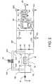
- FIG. 1depicts an electronic circuit that comprises an embodiment of the invention.
- FIG. 2depicts another embodiment of the present invention.
- numeral 10designates a vehicle power source, either a battery or rectified alternator output.
- Leads 12 R and 12 Lconnect the power source 10 to ganged switches 14 R and 14 L which are depicted in open condition.
- the two pairs of open contactsrepresent, on the left, a vehicle turn signal switch which is manually closed by pushing the control stalk up to initiate a right turn or down to initiate a left turn.
- Such manual actuationsimultaneously closes one or the other of open switch contacts on the right side of the flasher, depending on whether a right or left turn is to be executed.
- the switches on the right and left sides of the flashermay be physically connected together or connected with a servo.
- silicon diode 26blocks reverse flow of pulses into the left turn signal lamps 24 L.
- silicon diode 30blocks reverse flow of pulses into the right turn signal lamps 20 R.
- Numeral 32designates a 4-way hazard warning switch, normally configured as a double bordered triangle on a push button and located on a vehicle dashboard or the vehicle steering column.
- button 32When button 32 is pushed down, its two pair of moving contacts abut the two pair of stationary contacts which creates a circuit from power source 10 through leads 32 A, 32 B, flasher 16 , lead 32 C and lead 32 D.
- Lead 32 Dtransmits the pulses to a T intersection (arrow 28 ) through which the pulses flow into leads 18 R and 22 L.
- a T intersectionarrow 28
- all four lamps 20 R and 24 Lbegin flashing a conventional 4-way hazard warning signal, in the front and rear of the vehicle.
- Leads 18 R and 22 Lare connected by a bridge circuit comprising resistors 34 which serve as inputs to AND gate 36 .
- the output terminal of AND gate 36is connected preferably to an array of LED diodes 38 which preferably emits a yellow color when energized.
- AND gate 36remains nonconductive if only one of resistors 34 is electrified. Therefore, when right or left turn signals are made, only the lamp pairs 20 R or 24 L undergo flashing and, therefore, current cannot flow through the gate 36 . If, however, a 4-way hazard warning signal is generated by button 32 , all four lamps 20 R and 24 L begin simultaneously flashing. As a result, both resistors 34 become electrified by the pulses emitted from flasher 16 , AND gate 36 becomes conductive and the pulses flow through it to energize LED array 38 . Thus, a more effective and attention-getting triangular flashing hazard warning signal is automatically generated in the vehicle's rear. This flashing triangle may be uniformly colored yellow in vehicles which have yellow colored turn signal lamps, or multicolored if the turn signal lamps emit amber or red flashing lights.
- the circuitcomprising resistors 34 , AND gate 36 and associated leads functions as a monitor which detects whether or not the turn signal lamps 20 R and 24 L are or are not simultaneously flashing. If not, no flashing of the LED array 38 can begin. If simultaneous flashing of all four lamps turn signal lamps begins, due to initiation of a 4-way hazard signal, LED array is activated to also flash simultaneously and synchronously with turn signal lamps 20 R and 24 L. Resistors 34 are included to reduce the voltage from flasher 14 to a voltage that is within the specifications of the AND gate 36 .
- the illustrative embodimentgreatly facilitates retrofitting this improved hazard warning signal into existing vehicles. All of the components are quite inexpensive, in the range of cents to a modest number of dollars in unit costs.
- the required parts, two resistors, AND gate, LED array and their associated leadscan be assembled in a common housing from which two leads can extend in sufficient length for electrical attachment to the vehicle.
- the outboard resistor leadscan be connected to the sockets that transmit pulses to the turn signal lamps or spliced to the hot leads that transmit the pulses to the lamps.
- the LED array ground leadcan be fixed into contact with any electrically conductive surface or component of the vehicle.
- FIG. 2shows a second embodiment of the invention where the voltages on leads 18 R and 22 L are compared by comparator circuit 40 .
- the comparator circuit 40is connected to lead 18 R by means of lead 41 and to lead 22 L by means of lead 42 .
- the comparator circuit 40comprises a high voltage AND gate suitable for use with the voltages emanating from the flasher and rectifier circuit 44 . It is also connected to lead 22 L by means of rectifier circuit 44 and lead 45 that deliver a rectified supply voltage to the AND gate.
- the AND gatesupplies relay 46 with necessary power to close the relay and connect apex light 48 to lead 18 R by means of lead 50 .
- the 4-way hazard switch 32When the 4-way hazard switch 32 is depressed, the flasher causes the same fluctuating voltage to be present on leads 18 R and 24 L.
- the embodiment in FIG. 2can be retrofitted in a vehicle by placing apex light 48 an the comparator 40 , and relay 46 in a housing, positioning it at the rear of the vehicle, and connecting it to the leads supplying the rear turn signal lights.
- the housingdoes not require direct connection to the power source 10 .
Landscapes
- Engineering & Computer Science (AREA)
- Mechanical Engineering (AREA)
- Lighting Device Outwards From Vehicle And Optical Signal (AREA)
Abstract
Description
Claims (27)
Priority Applications (1)
| Application Number | Priority Date | Filing Date | Title |
|---|---|---|---|
| US12/397,038US8044790B2 (en) | 2009-03-03 | 2009-03-03 | Retrofit circuitry for enhanced vehicle hazard warning lights |
Applications Claiming Priority (1)
| Application Number | Priority Date | Filing Date | Title |
|---|---|---|---|
| US12/397,038US8044790B2 (en) | 2009-03-03 | 2009-03-03 | Retrofit circuitry for enhanced vehicle hazard warning lights |
Publications (2)
| Publication Number | Publication Date |
|---|---|
| US20100225465A1 US20100225465A1 (en) | 2010-09-09 |
| US8044790B2true US8044790B2 (en) | 2011-10-25 |
Family
ID=42677745
Family Applications (1)
| Application Number | Title | Priority Date | Filing Date |
|---|---|---|---|
| US12/397,038Expired - Fee RelatedUS8044790B2 (en) | 2009-03-03 | 2009-03-03 | Retrofit circuitry for enhanced vehicle hazard warning lights |
Country Status (1)
| Country | Link |
|---|---|
| US (1) | US8044790B2 (en) |
Families Citing this family (9)
| Publication number | Priority date | Publication date | Assignee | Title |
|---|---|---|---|---|
| US20150158417A1 (en)* | 2009-12-08 | 2015-06-11 | Yehoshua Rahamim Levi | Portable Illumination Brake and Indicator Lights Panel for Vehicle |
| US20160144778A1 (en) | 2014-11-24 | 2016-05-26 | David M. Tucker | Enhanced communication system for vehicle hazard lights |
| KR102310984B1 (en)* | 2016-09-29 | 2021-10-07 | 이에스에스-헬프, 아이엔씨. | Improved communication system for vehicle emergency lights |
| EP3894275B1 (en) | 2018-12-11 | 2025-04-02 | Ess-Help, Inc. | Enhanced operation of vehicle hazard and lighting communication systems |
| CA3133773A1 (en) | 2019-03-15 | 2020-09-24 | Ess-Help, Inc. | Control of high visibility vehicle light communication systems |
| US11518298B2 (en) | 2019-03-15 | 2022-12-06 | ESS-Help, lnc. | High visibility lighting for autonomous vehicles |
| US11590887B2 (en) | 2019-03-15 | 2023-02-28 | Ess-Help, Inc. | Control of high visibility vehicle light communication systems |
| AU2020248490B2 (en) | 2019-03-28 | 2021-11-18 | Emergency Safety Solutions, Inc. | Remote vehicle hazard and communication beacon |
| US12109938B2 (en) | 2019-08-12 | 2024-10-08 | Ess-Help, Inc. | System for communication of hazardous vehicle and road conditions |
Citations (5)
| Publication number | Priority date | Publication date | Assignee | Title |
|---|---|---|---|---|
| US5119067A (en)* | 1990-06-06 | 1992-06-02 | Robert Adell | Rear vehicle courtesy bright light dimming signal system |
| US5311412A (en)* | 1993-07-06 | 1994-05-10 | Yang Chang An | Structure of a variable triangular warning light on the third braking light in the rear turbulence plate of an automobile |
| US6243008B1 (en)* | 2000-08-07 | 2001-06-05 | Walter Korabiak | Automobile rear light warning display |
| US20090303029A1 (en)* | 2008-06-10 | 2009-12-10 | Tritel, Llc | Continuous enhanced vehicle hazard warning lights |
| US20100026478A1 (en)* | 2008-07-29 | 2010-02-04 | Tritel, Llc | Turn signals generated during operation of vehicle hazard warning lights |
- 2009
- 2009-03-03USUS12/397,038patent/US8044790B2/ennot_activeExpired - Fee Related
Patent Citations (5)
| Publication number | Priority date | Publication date | Assignee | Title |
|---|---|---|---|---|
| US5119067A (en)* | 1990-06-06 | 1992-06-02 | Robert Adell | Rear vehicle courtesy bright light dimming signal system |
| US5311412A (en)* | 1993-07-06 | 1994-05-10 | Yang Chang An | Structure of a variable triangular warning light on the third braking light in the rear turbulence plate of an automobile |
| US6243008B1 (en)* | 2000-08-07 | 2001-06-05 | Walter Korabiak | Automobile rear light warning display |
| US20090303029A1 (en)* | 2008-06-10 | 2009-12-10 | Tritel, Llc | Continuous enhanced vehicle hazard warning lights |
| US20100026478A1 (en)* | 2008-07-29 | 2010-02-04 | Tritel, Llc | Turn signals generated during operation of vehicle hazard warning lights |
Also Published As
| Publication number | Publication date |
|---|---|
| US20100225465A1 (en) | 2010-09-09 |
Similar Documents
| Publication | Publication Date | Title |
|---|---|---|
| US8044790B2 (en) | Retrofit circuitry for enhanced vehicle hazard warning lights | |
| US6515584B2 (en) | Distinctive hazard flash patterns for motor vehicles and for portable emergency warning devices with pulse generators to produce such patterns | |
| US11372039B2 (en) | Trailer lighting outage detection circuit | |
| US6181243B1 (en) | Auxiliary auto signlight system | |
| CN110027467A (en) | Especially with the driving direction indicator thereof of wiping effect and warning against danger function | |
| AU2018202829B2 (en) | Trailer signal converter | |
| US5856779A (en) | Motorcycle brake light enhancement system | |
| US7352278B2 (en) | Vehicle hazard warning lights | |
| US20040183462A1 (en) | Control circuit for signal lamps of a vehicle | |
| US4837554A (en) | Motor vehicle brake-state of motion signal-lights indicator | |
| DE102011006423A1 (en) | Light control device for motor vehicle, has control unit that performs control-activation of lighting elements of lamps, based on request of emission of signal light and daytime running light | |
| US20170100975A1 (en) | Automatic Trailer Lighting Control | |
| US9238432B1 (en) | Customizable modulator for vehicular braking indication | |
| KR101078142B1 (en) | Vehicle U-turn and Stop Display | |
| US3609681A (en) | Control circuit for alternately flashing automobile headlamps | |
| JP2003341426A (en) | Rear-end collision preventing device for automobile | |
| US6111500A (en) | Automatic brakes initiated annunciator | |
| US9145085B2 (en) | Reverse activated signaling circuit | |
| US4613846A (en) | Light system for trucks | |
| KR200218247Y1 (en) | Automatic turn on and off apparatus of warning signal by parking brake | |
| ITRM940632A1 (en) | DIRECTIONAL AND EMERGENCY FLASHING SYSTEM FOR VEHICLES | |
| KR200352261Y1 (en) | a head-light alarm apparatus for automobile | |
| KR0171705B1 (en) | Disconnection of wire warning device for indicating light of a car | |
| KR0180847B1 (en) | Sign device of emergency parking of a car | |
| KR20090108939A (en) | Lamp Breaker Notification Device |
Legal Events
| Date | Code | Title | Description |
|---|---|---|---|
| AS | Assignment | Owner name:TRITEL, LLC, MASSACHUSETTS Free format text:ASSIGNMENT OF ASSIGNORS INTEREST;ASSIGNORS:EKCHIAN, JACK A.;TERZIAN, BERJ A.;REEL/FRAME:022338/0432 Effective date:20090209 | |
| AS | Assignment | Owner name:TRIXCEL, LLP, MASSACHUSETTS Free format text:ASSIGNMENT OF ASSIGNORS INTEREST;ASSIGNOR:TRITEL, LLC;REEL/FRAME:023814/0757 Effective date:20100119 | |
| STCF | Information on status: patent grant | Free format text:PATENTED CASE | |
| FPAY | Fee payment | Year of fee payment:4 | |
| FEPP | Fee payment procedure | Free format text:MAINTENANCE FEE REMINDER MAILED (ORIGINAL EVENT CODE: REM.); ENTITY STATUS OF PATENT OWNER: SMALL ENTITY | |
| LAPS | Lapse for failure to pay maintenance fees | Free format text:PATENT EXPIRED FOR FAILURE TO PAY MAINTENANCE FEES (ORIGINAL EVENT CODE: EXP.); ENTITY STATUS OF PATENT OWNER: SMALL ENTITY | |
| STCH | Information on status: patent discontinuation | Free format text:PATENT EXPIRED DUE TO NONPAYMENT OF MAINTENANCE FEES UNDER 37 CFR 1.362 | |
| FP | Lapsed due to failure to pay maintenance fee | Effective date:20191025 |