US8044661B2 - Method for determining a three-dimensional reconstruction of an examination object - Google Patents
Method for determining a three-dimensional reconstruction of an examination objectDownload PDFInfo
- Publication number
- US8044661B2 US8044661B2US12/080,460US8046008AUS8044661B2US 8044661 B2US8044661 B2US 8044661B2US 8046008 AUS8046008 AUS 8046008AUS 8044661 B2US8044661 B2US 8044661B2
- Authority
- US
- United States
- Prior art keywords
- projection images
- provisional
- images
- modified
- data values
- Prior art date
- Legal status (The legal status is an assumption and is not a legal conclusion. Google has not performed a legal analysis and makes no representation as to the accuracy of the status listed.)
- Expired - Fee Related, expires
Links
Images


Classifications
- G—PHYSICS
- G06—COMPUTING OR CALCULATING; COUNTING
- G06T—IMAGE DATA PROCESSING OR GENERATION, IN GENERAL
- G06T11/00—2D [Two Dimensional] image generation
- G06T11/003—Reconstruction from projections, e.g. tomography
- G06T11/005—Specific pre-processing for tomographic reconstruction, e.g. calibration, source positioning, rebinning, scatter correction, retrospective gating
- A—HUMAN NECESSITIES
- A61—MEDICAL OR VETERINARY SCIENCE; HYGIENE
- A61B—DIAGNOSIS; SURGERY; IDENTIFICATION
- A61B6/00—Apparatus or devices for radiation diagnosis; Apparatus or devices for radiation diagnosis combined with radiation therapy equipment
- A61B6/52—Devices using data or image processing specially adapted for radiation diagnosis
- A61B6/5258—Devices using data or image processing specially adapted for radiation diagnosis involving detection or reduction of artifacts or noise
Definitions
- the present inventionrelates to a determination method for determining a definitive three-dimensional reconstruction of an examination object on the basis of a plurality of two-dimensional original projection images.
- Metallic objectsfor example catheters in vessels, platinum coils in aneurysms, dental fillings, protheses etc.
- volume reconstructions from planar projection datasuch as is acquired for example by means of C-arm systems and associated flat-panel detectors.
- Iterative reconstruction methodsare also known. With these reconstruction methods, streak artifacts can be reduced by including the data acquisition and the data statistics in the reconstruction algorithm. Iterative reconstruction methods are very compute-intensive, however.
- the object of the present inventionconsists in providing a determination method of the kind referred to in the introduction and the equipment-related objects corresponding herewith, by means of which the metal areas can be reliably determined even in unfavorable constellations (small metal objects and/or areas filled with contrast agent).
- a provisional three-dimensional reconstruction of the examination objectis determined on the basis of the original projection images.
- provisional metal volumesare determined by means of segmentation.
- Corresponding provisional metal areasare determined by mapping the provisional metal volumes into the original projection images.
- Edge zones of the provisional metal areasare determined in the original projection images. Edge points of the edge zones are selected.
- Data values of the original projection images which are assigned to locations that lie in the provisional metal areasare modified as a function of data values which are assigned to the selected edge points.
- modified projection imagesare determined.
- a differential imageis determined in each case on the basis of the respective original projection image and the corresponding modified projection image.
- Definitive metal areasare determined in the differential images by means of segmentation. The differential images, with the respective definitive metal areas subtracted, are added to the corresponding modified projection image in each case.
- the definitive three-dimensional reconstruction of the examination objectis determined on the basis of the modified projection images including the added differential images.
- the modified data valuesit is possible, for the purpose of determining the modified data values, to make use of the data values of the edge zones as they are. Preferably, however, the data values of the edge zones are filtered in order to reduce noise effects.
- the modified data valuesit is possible, for the purpose of determining the modified data values, to make use of the data values of all of the edge zones.
- the selected edge pointsinclude only a part of the edge zones.
- the computing overhead for determining the modified data valuescan be significantly reduced.
- the modified data valuesare changed only to an insignificant extent.
- the modified data valuesare determined uniformly for all locations that lie in the provisional metal areas.
- the modified data valuesare determined as a function of the location in the provisional metal area which is assigned to the data value that is to be modified.
- the modified data valuesit is possible for the modified data values to be determined on the basis of the data values of the selected edge points and the distances of the location assigned to the respective data value that is to be modified in the provisional metal area from the selected edge points.
- At least one two-dimensional representation of the definitive three-dimensional reconstruction of the examination objectis determined.
- the two-dimensional representationcan be, for example, a perspective projection, a parallel projection or a representation of a layer of the three-dimensional reconstruction. It can be of advantage if definitive metal volumes are determined on the basis of the definitive metal areas and the definitive metal volumes are inserted into the two-dimensional representation of the definitive three-dimensional reconstruction.
- the modified projection imagescan be used directly for determining the definitive three-dimensional reconstruction of the examination object.
- the modified projection images, including the added differential imagesare preprocessed by means of an image preprocessing method that acts two-dimensionally and the definitive three-dimensional reconstruction of the examination object is determined on the basis of the preprocessed projection images. For example, a gradient determination with subsequent smoothing can be performed.
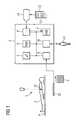
- FIG. 1a block diagram of a data acquisition and processing device
- FIG. 2a flowchart
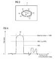
- FIG. 3a two-dimensional projection image
- FIG. 4a line in a projection image
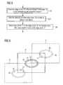
- FIG. 5a flowchart
- FIG. 6several two-dimensional projection images
- FIG. 7a flowchart
- FIG. 8a line in a modified projection image.
- a computer 1is supplied with a plurality (for example 40 to 400) two-dimensional projection images P of an examination object 2 .
- the examination object 2is normally a human being.
- the projection images Pare typically fluoroscopic images that are acquired by means of an X-ray system 3 .
- the examination object 2can be disposed for example on a patient examination table 4 .
- a three-dimensional reconstruction of the examination object 2is to be determined by the computer 1 using the projection images P. Determination methods of this kind are generally known as such to persons skilled in the art. The preconditions which must be fulfilled by the projection images P so that the determination of the three-dimensional reconstruction will be possible are also known to persons skilled in the art. The basic principle for determining a three-dimensional reconstruction on the basis of a plurality of projection images P will therefore not be dealt with in greater detail below.
- the computer 1is embodied in typical fashion. It includes a microprocessor 5 , a working memory (RAM) 6 , a mass storage device 7 (e.g. a hard disk), a projection interface 8 to the X-ray system 3 , a data interface 9 (e.g. a USB port) and a user interface 10 (e.g. keyboard, mouse and display).
- a microprocessor 5e.g. a central processing unit (CPU) 6
- RAMworking memory
- mass storage device 7e.g. a hard disk
- a projection interface 8 to the X-ray system 3e.g. a hard disk
- a data interface 9e.g. a USB port
- a user interface 10e.g. keyboard, mouse and display
- the computer 1communicates with a user 11 via the user interface 10 .
- the computer 1can receive a computer program 12 and store it in the mass storage device 7 .
- the computer program 12has machine code 13 which can be executed by the computer 1 (that is to say by the microprocessor 5 of the computer 1 ).
- the computer program 12is stored on a data medium 14 (e.g. a USB memory stick) and can be supplied to the computer 1 in this way.
- a data medium 14e.g. a USB memory stick
- the computer 1loads the computer program 12 from the mass storage device 7 into the working memory 6 and executes it.
- the execution of the computer program 12causes the computer 1 to carry out a determination method for the purpose of determining a definitive three-dimensional reconstruction of the examination object 2 . The determination method is explained in more detail below with reference to FIGS. 2 to 4 .
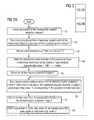
- the computer 1initially receives the plurality of two-dimensional projection images P in a step S 1 .
- the received projection images Pare referred to in the following as original projection images P.
- a step S 2the computer 1 determines a provisional three-dimensional reconstruction of the examination object 2 on the basis of the original projection images P.
- the corresponding determination methodsare known as such to persons skilled in the art.
- the so-called Feldkamp algorithmmay be mentioned purely by way of example.
- Step S 3the computer 1 receives a first threshold value SW 1 from the user 11 .
- Step S 3is merely optional and is therefore represented by a dashed line in FIG. 2 . If it is omitted, either the first threshold value SW 1 is predefined as a fixed value or the first threshold value SW 1 is determined automatically by the computer 1 . An automatic determination can be performed for example on the basis of the data values of the provisional reconstruction.
- a step S 4the computer 1 determines provisional metal volumes in the provisional three-dimensional reconstruction by means of segmentation.
- the computer 1in particular compares the volume data values of the provisional three-dimensional reconstruction individually with the first threshold value SW 1 . If the volume data values are greater than the first threshold value SW 1 , the computer 1 classifies the corresponding volume element as metal, and otherwise as non-metal.
- a step S 5the computer 1 selects a first of the original projection images P.
- a step S 6the computer 1 maps the provisional metal volumes into the currently selected original projection image P. In this way it determines, in the respective original projection image P, provisional metal areas 15 that correspond to the provisional metal volumes (see FIG. 3 ).
- the computer 1determines edge zones 16 of the provisional metal areas 15 in the selected original projection image P. For example, the computer 1 can assign a data value “1” to the provisional metal areas 15 , and a data value “0” to the remaining areas.
- the edge zones 16can be determined for example by means of a simple edge detection which is generally known to persons skilled in the art. It should be pointed out here as a matter of form that the term “edge zones” is meant to denote those areas of the original projection image P which border on the provisional metal areas 15 , but still lie outside the provisional metal areas 15 .
- a step S 8the computer 1 selects edge points 17 of the edge zones 16 .
- the computer 1selects at this juncture all points 17 that lie in the edge zones 16 , though preferably (compare FIG. 3 ) the computer selects only a part of the edge zones 16 , for example every fifth, every eighth or every tenth edge point 17 .
- the edge points 17are selected in such a way that they are distributed (at least essentially) evenly over the edge zones 16 .
- a step S 9the computer 1 modifies data values Di of the original projection images P which are assigned to locations 18 that lie in the provisional metal areas 15 .
- the data values Diare modified preferably as a function of data values Dj which are assigned to the selected edge points 17 . In this way the computer determines modified projection images P′.
- the computer 1determines a single data value in the course of step S 9 and replaces all data values Di which are assigned to locations 18 within the metal areas 15 by this one modified data value.
- the computer 1determines the modified data values Di′ as a function of the location 18 in the provisional metal area 15 which is assigned to the data value Di that is to be modified.
- the computer 1can weight the data values Dj of the selected edge points 17 with weighting factors gij, which depend on the distances aij of the respective selected edge points 17 from the respective location 18 .
- the computer 1determines the modified data values Di′ on the basis of the data values Dj of the selected edge points 17 and the distances aij of the location 18 assigned to the respective data value Di that is to be modified in the provisional metal area 15 from the selected edge points 17 .
- the weighting factors gijare intended to ensure in particular that selected edge points 17 which lie closer to the respective location 18 than other edge points 17 are weighted more heavily.
- the weighting factor gij of the jth edge point 17can be determined for calculating the modified data value Di′ of the ith location 18 in the metal area 15 as
- aijis the distance of the ith location 18 in the metal area 15 from the jth edge point 17
- bis a suitably chosen exponent
- Niis a normalization factor. It is defined as
- a step S 10the computer 1 determines a differential image D on the basis of the respective original projection image P and the corresponding modified projection image P′.
- step S 11the computer 1 receives a second threshold value SW 2 from the user 11 .
- step S 11is also merely optional and is therefore represented by a dashed line in FIG. 2 .
- the second threshold value SW 2(analogously to the first threshold value SW 1 ) can be specified as a fixed value.
- the second threshold value SW 2can be determined automatically by the computer 1 , for example on the basis of the data values of the respective differential image D.
- a step S 12the computer 1 determines definitive metal areas 19 by means of segmentation in the differential image D (compare FIG. 4 ).
- the computer 1can compare the data values with the second threshold value SW 2 in the differential images D. If the respective data value exceeds the second threshold value SW 2 , the corresponding location is assigned to a definitive metal area 19 ; otherwise it is classified as non-metal.
- Step S 12is based on the knowledge that in the ideal case the differential images D only contain metal. It is, however, possible that they also include other constituents besides metal. Generally, however, the data values that are attributable to metal are considerably greater than the data values that are not attributable to metal. In particular, the data values that are not attributable to metal are, according to FIG. 4 , typically maximally around half as large as the data values that are attributable to metal. Therefore the definitive metal areas 19 can be separated from the remaining areas in the differential image D by suitable selection of the second threshold values SW 2 .
- a step S 13the computer 1 determines a residual image R.
- the computer 1adds the residual image R to the modified projection image P′ in step S 13 .
- the residual image Rcorresponds to the differential image D with the definitive metal areas 19 of the respective differential image D deducted.
- step S 14the computer 1 checks whether it has already performed steps S 6 to S 13 for all the original projection images P. If this is not the case, the computer 1 proceeds to a step S 15 .
- step S 15the computer 1 selects another, hitherto not yet selected original projection image P. It then returns to step S 6 .
- step S 16the computer 1 determines on the basis of the modified projection images P′ (including the added differential images D) the definitive three-dimensional reconstruction of the examination object 2 .
- step S 17the computer 1 determines at least one two-dimensional representation of the definitive three-dimensional reconstruction of the examination object 2 and outputs this representation to the user 11 via the user interface 10 .
- FIGS. 5 to 7The inventive determination method explained in detail above can be modified in various ways. This is explained in more detail below with reference to FIGS. 5 to 7 .
- the modifications of FIGS. 5 to 7can in this case be realized independently of one another. They can therefore be realized individually, in pairs and collectively.
- step S 21is inserted between steps S 7 and S 8 .
- the computer 1filters the data values of the edge zones 16 .
- the filteringis intended to reduce noise effects.
- Inserting step S 21is beneficial in particular when the selected edge points 17 comprise only a part of the edge zones 16 . This is also represented thus in FIG. 5 . In principle, however, the insertion of step S 21 can be implemented independently of whether the selected edge points 17 comprise all of the edge zones 16 or only a part of the edge zones 16 .
- step S 9it is possible in the course of step S 9 also to include edge points 17 of provisional metal areas 15 in locally adjacent original projection images P in the determination of the modified data values Di′.
- udesignates the column coordinates of the original projection images P 1 , P 2 in length units, v the row coordinates in length units.
- Ris the distance of the detector 20 from a center of rotation 21 .
- steps S 16 and S 17are modified or supplemented according to FIG. 7 .
- Step S 16 from FIG. 2is in this case modified in FIG. 7 by steps S 31 and S 32
- step S 17is supplemented by steps S 33 and S 34 .
- the two measures of FIG. 7that is to say steps S 31 and S 32 on the one hand and steps S 33 and S 34 on the other) can in this case be realized independently of one another. They can therefore be realized individually or in combination.
- step S 31the computer 1 performs image preprocessing of the modified projection images P′ that acts in a two-dimensional manner.
- the residual images Rhave already been added to the modified projection images P′.
- the computer 1can perform a gradient detection together with subsequent smoothing of large gradients.
- step S 32the computer 1 determines the definitive three-dimensional reconstruction of the examination object 2 on the basis of the preprocessed projection images P′.
- step S 33the computer 1 determines definitive metal volumes and their locations, relative to the definitive three-dimensional reconstruction of the examination object 2 , on the basis of the definitive metal areas 19 .
- step S 34the computer 1 inserts the definitive metal volumes into the two-dimensional representation of the definitive three-dimensional reconstruction.
- the determination methods according to the inventionhave many advantages. In particular they are easy to implement, and operate robustly, reliably and accurately. Furthermore they also lead to good results in cases where determination methods of the prior art fall short (in spite of artifact reduction there).
Landscapes
- Engineering & Computer Science (AREA)
- Health & Medical Sciences (AREA)
- Life Sciences & Earth Sciences (AREA)
- Medical Informatics (AREA)
- Physics & Mathematics (AREA)
- Pathology (AREA)
- Molecular Biology (AREA)
- Biophysics (AREA)
- Nuclear Medicine, Radiotherapy & Molecular Imaging (AREA)
- Optics & Photonics (AREA)
- Computer Vision & Pattern Recognition (AREA)
- Radiology & Medical Imaging (AREA)
- Biomedical Technology (AREA)
- Heart & Thoracic Surgery (AREA)
- High Energy & Nuclear Physics (AREA)
- Surgery (AREA)
- Animal Behavior & Ethology (AREA)
- General Health & Medical Sciences (AREA)
- Public Health (AREA)
- Veterinary Medicine (AREA)
- General Physics & Mathematics (AREA)
- Theoretical Computer Science (AREA)
- Apparatus For Radiation Diagnosis (AREA)
Abstract
Description
so that consequently
applies.
d12=√{square root over ((ρ12)2+(ν2−ν1)2)}{square root over ((ρ12)2+(ν2−ν1)2)} (4)
where the relation
applies. The
Claims (12)
Applications Claiming Priority (3)
| Application Number | Priority Date | Filing Date | Title |
|---|---|---|---|
| DE102007016319 | 2007-04-04 | ||
| DE200710016319DE102007016319A1 (en) | 2007-04-04 | 2007-04-04 | Determination method for determining a final three-dimensional reconstruction of an examination subject by multiple segmentation of metal and corresponding technical objects |
| DE102007016319.5 | 2007-04-04 |
Publications (2)
| Publication Number | Publication Date |
|---|---|
| US20080247624A1 US20080247624A1 (en) | 2008-10-09 |
| US8044661B2true US8044661B2 (en) | 2011-10-25 |
Family
ID=39736171
Family Applications (1)
| Application Number | Title | Priority Date | Filing Date |
|---|---|---|---|
| US12/080,460Expired - Fee RelatedUS8044661B2 (en) | 2007-04-04 | 2008-04-03 | Method for determining a three-dimensional reconstruction of an examination object |
Country Status (2)
| Country | Link |
|---|---|
| US (1) | US8044661B2 (en) |
| DE (1) | DE102007016319A1 (en) |
Cited By (2)
| Publication number | Priority date | Publication date | Assignee | Title |
|---|---|---|---|---|
| CN106204721A (en)* | 2016-06-30 | 2016-12-07 | 扬州大学 | The non-complete face model restorative procedure in local based on photo |
| US10610185B2 (en)* | 2016-03-28 | 2020-04-07 | Canon Medical Systems Corporation | X-ray CT apparatus including processing circuitry to perform a metal-artifact reducing process |
Families Citing this family (8)
| Publication number | Priority date | Publication date | Assignee | Title |
|---|---|---|---|---|
| DE102008009128B4 (en)* | 2008-02-14 | 2014-11-06 | Siemens Aktiengesellschaft | Tomosynthetic image reconstruction method and diagnostic device using this method |
| JP5498481B2 (en)* | 2009-03-24 | 2014-05-21 | オリンパス株式会社 | Fluorescence observation apparatus, fluorescence observation system, operation method of fluorescence observation apparatus, and fluorescence image processing method performed by fluorescence observation apparatus |
| DE102011005715A1 (en) | 2011-03-17 | 2012-09-20 | Siemens Aktiengesellschaft | Method for obtaining a 3D image data set freed from traces of a metal object |
| DE102011017710B4 (en) | 2011-04-28 | 2021-03-04 | Siemens Healthcare Gmbh | Method for providing a 3D x-ray image data set for a moving object with highly absorbent material |
| JP5926909B2 (en) | 2011-09-07 | 2016-05-25 | オリンパス株式会社 | Fluorescence observation equipment |
| EP2747655B1 (en)* | 2011-10-24 | 2019-02-06 | Koninklijke Philips N.V. | Apparatus and method for motion compensated second pass metal artifact correction for ct slice images |
| US9486178B2 (en) | 2012-08-31 | 2016-11-08 | Shimadzu Corporation | Radiation tomographic image generating apparatus, and radiation tomographic image generating method |
| DE102013218325A1 (en) | 2013-09-12 | 2015-03-12 | Siemens Aktiengesellschaft | Generation of a measure of the influence of metal artefacts on reconstructed density values |
Citations (12)
| Publication number | Priority date | Publication date | Assignee | Title |
|---|---|---|---|---|
| DE19526234A1 (en) | 1994-07-21 | 1996-01-25 | Gen Electric | Reduction of artifacts by z-dependent filtering of three-dimensional cone bundle data |
| US6004269A (en)* | 1993-07-01 | 1999-12-21 | Boston Scientific Corporation | Catheters for imaging, sensing electrical potentials, and ablating tissue |
| US6139183A (en)* | 1997-10-17 | 2000-10-31 | Siemens Aktiengesellschaft | X-ray exposure system for 3D imaging |
| US6206566B1 (en)* | 1998-11-02 | 2001-03-27 | Siemens Aktiengesellschaft | X-ray apparatus for producing a 3D image from a set of 2D projections |
| US6324296B1 (en)* | 1997-12-04 | 2001-11-27 | Phasespace, Inc. | Distributed-processing motion tracking system for tracking individually modulated light points |
| US6379041B1 (en)* | 1998-11-02 | 2002-04-30 | Siemens Aktiengesellschaft | X-ray apparatus for producing a 3D image from a set of 2D projections |
| US6634088B1 (en)* | 2000-03-31 | 2003-10-21 | Fonar Corporation | Method and apparatus for shimming a magnet to control a three-dimensional field |
| DE10306016A1 (en) | 2003-02-13 | 2004-09-02 | Siemens Ag | Three-dimensional object imaging method wherein object is reconstructed from several projections for e.g. computer tomography, partially alters projection data to form altered projections which are then combined |
| US6845142B2 (en)* | 2001-06-21 | 2005-01-18 | Kabushiki Kaisha Toshiba | Image processing involving correction of beam hardening |
| US7280686B2 (en)* | 2002-05-29 | 2007-10-09 | Siemens Aktiengesellschaft | Computer-supported image reconstruction method for a three-dimensional subject |
| US20080253522A1 (en)* | 2007-04-11 | 2008-10-16 | Searete Llc, A Limited Liability Corporation Of The State Of Delaware | Tool associated with compton scattered X-ray visualization, imaging, or information provider |
| US7555157B2 (en)* | 2001-09-07 | 2009-06-30 | Geoff Davidson | System and method for transforming graphical images |
Family Cites Families (1)
| Publication number | Priority date | Publication date | Assignee | Title |
|---|---|---|---|---|
| EP1442147B1 (en)* | 2001-10-29 | 2005-10-12 | Nippon Steel Corporation | Steel sheet for vitreous enameling excellent in workability and fish scale resistance, and method for producing the same |
- 2007
- 2007-04-04DEDE200710016319patent/DE102007016319A1/ennot_activeWithdrawn
- 2008
- 2008-04-03USUS12/080,460patent/US8044661B2/ennot_activeExpired - Fee Related
Patent Citations (13)
| Publication number | Priority date | Publication date | Assignee | Title |
|---|---|---|---|---|
| US6004269A (en)* | 1993-07-01 | 1999-12-21 | Boston Scientific Corporation | Catheters for imaging, sensing electrical potentials, and ablating tissue |
| DE19526234A1 (en) | 1994-07-21 | 1996-01-25 | Gen Electric | Reduction of artifacts by z-dependent filtering of three-dimensional cone bundle data |
| US6139183A (en)* | 1997-10-17 | 2000-10-31 | Siemens Aktiengesellschaft | X-ray exposure system for 3D imaging |
| US6324296B1 (en)* | 1997-12-04 | 2001-11-27 | Phasespace, Inc. | Distributed-processing motion tracking system for tracking individually modulated light points |
| US6206566B1 (en)* | 1998-11-02 | 2001-03-27 | Siemens Aktiengesellschaft | X-ray apparatus for producing a 3D image from a set of 2D projections |
| US6379041B1 (en)* | 1998-11-02 | 2002-04-30 | Siemens Aktiengesellschaft | X-ray apparatus for producing a 3D image from a set of 2D projections |
| US6634088B1 (en)* | 2000-03-31 | 2003-10-21 | Fonar Corporation | Method and apparatus for shimming a magnet to control a three-dimensional field |
| US6845142B2 (en)* | 2001-06-21 | 2005-01-18 | Kabushiki Kaisha Toshiba | Image processing involving correction of beam hardening |
| US7555157B2 (en)* | 2001-09-07 | 2009-06-30 | Geoff Davidson | System and method for transforming graphical images |
| US7280686B2 (en)* | 2002-05-29 | 2007-10-09 | Siemens Aktiengesellschaft | Computer-supported image reconstruction method for a three-dimensional subject |
| DE10306016A1 (en) | 2003-02-13 | 2004-09-02 | Siemens Ag | Three-dimensional object imaging method wherein object is reconstructed from several projections for e.g. computer tomography, partially alters projection data to form altered projections which are then combined |
| US7148903B2 (en)* | 2003-02-13 | 2006-12-12 | Siemens Aktiengesellschaft | Image reconstruction method and computer program product |
| US20080253522A1 (en)* | 2007-04-11 | 2008-10-16 | Searete Llc, A Limited Liability Corporation Of The State Of Delaware | Tool associated with compton scattered X-ray visualization, imaging, or information provider |
Non-Patent Citations (5)
| Title |
|---|
| A.H. Mahnken, R. Raupach, J.E. Wildberger, B. Jung, N. Heussen, T.G. Flohr, R.W. Günther, S. Schaller; "A new algorithm for metal artifact reduction in computed tomography-in vitro and in vivo evaluation after total hip replacement"; Investigative Radiology; Dec. 2003; vol. 38, No. 12; pp. 769-775. |
| B. De Man, J. Nuyts, P. Dupont, G. Marchal, and P. Suetens; "Reduction of metal streak artifacts in x-ray computed tomography using a transmission maximum a posteriori algorithm"; IEEE Transactions on Nuclear Science, 2000, pp. 977-981; vol. 47, No. 3. |
| D. Felsenberg, W. Kalender, R. Sokiranski, J. Ebersberger, R. Krämer; "Reduktion von Metallartefakten in der Computer Tomographie: Klinische Erfahrungen and Ergebnisse"; Electromedica, 1988; vol. 56, No. 3; pp. 97-104. |
| Kalender, Willi A.; Hebel, Robert; Ebersberger, Johannes; "Reduction of CT artifacts caused by metallic implants"; Radiology; Aug. 1987; vol. 164, No. 2, pp. 576-577. |
| T. Hinderling, P. Rüegsegger, M. Anliker, C. Dietschi; Computed tomography reconstruction from hollow projections: an application to in vivo evaluation of artificial hip joints; Journal of Computer Assisted Tomography; Feb. 1979; vol. 3, No. 1; pp. 52-57. |
Cited By (3)
| Publication number | Priority date | Publication date | Assignee | Title |
|---|---|---|---|---|
| US10610185B2 (en)* | 2016-03-28 | 2020-04-07 | Canon Medical Systems Corporation | X-ray CT apparatus including processing circuitry to perform a metal-artifact reducing process |
| CN106204721A (en)* | 2016-06-30 | 2016-12-07 | 扬州大学 | The non-complete face model restorative procedure in local based on photo |
| CN106204721B (en)* | 2016-06-30 | 2019-04-09 | 扬州大学 | Photo-Based Local Incomplete Face Model Restoration Method |
Also Published As
| Publication number | Publication date |
|---|---|
| DE102007016319A1 (en) | 2008-10-09 |
| US20080247624A1 (en) | 2008-10-09 |
Similar Documents
| Publication | Publication Date | Title |
|---|---|---|
| US8044661B2 (en) | Method for determining a three-dimensional reconstruction of an examination object | |
| JP5081390B2 (en) | Method and system for monitoring tumor burden | |
| Van Kriekinge et al. | Automatic quantification of left ventricular ejection fraction from gated blood pool SPECT | |
| CN108348206B (en) | Collateral flow modeling for non-invasive Fractional Flow Reserve (FFR) | |
| US8958620B2 (en) | Region of interest definition in cardiac imaging | |
| CN105830123B (en) | Compose image real time transfer | |
| US20040223636A1 (en) | Feature quantification from multidimensional image data | |
| US20110007956A1 (en) | Sinogram processing to reduce metal artifacts in computed tomography | |
| Cselényi et al. | A comparison of recent parametric neuroreceptor mapping approaches based on measurements with the high affinity PET radioligands [11C] FLB 457 and [11C] WAY 100635 | |
| US10664985B2 (en) | Determining a complexity value of a stenosis or a section of a vessel | |
| CN102085101A (en) | Method and device for identifying and assigning coronary calcification to a coronary vessel and computer program product | |
| WO2013056733A1 (en) | Out of plane artifact reduction in digital breast tomosynthesis and ct | |
| US8718342B2 (en) | Method and data-processing system for determining the proportion of calcium in coronary arteries | |
| EP3471054A1 (en) | Method for determining at least one object feature of an object | |
| EP4238500A1 (en) | Measurement of blood flow parameters | |
| EP2347391B1 (en) | Visualization and quantization of newly formed vasculature | |
| WO2011114243A1 (en) | Functional image data enhancement and/or enhancer | |
| EP3472804B1 (en) | Determining calcium content from spectral ct data | |
| CA2812998A1 (en) | Method of extracting contour of tomogram, and program and apparatus therefor | |
| US20020114510A1 (en) | Method of analyzing a data set comprising a volumetric representation of an object to be examined | |
| JP2021513054A (en) | Correction of standard capture value (SUV) scaling differences in serial positron emission tomography (PET) examinations using image alignment and regression analysis | |
| EP3484368B1 (en) | Identifying types of adipose tissue | |
| Spiesberger et al. | Processing of medical image sequences | |
| JP5132559B2 (en) | Digital image segmentation method and computer-readable program storage device | |
| JP2851057B2 (en) | Method and apparatus for automated analysis in digital x-ray images |
Legal Events
| Date | Code | Title | Description |
|---|---|---|---|
| AS | Assignment | Owner name:SIEMENS AKTIENGESELLSCHAFT, GERMANY Free format text:ASSIGNMENT OF ASSIGNORS INTEREST;ASSIGNOR:SCHOLZ, BERNHARD;REEL/FRAME:020806/0214 Effective date:20080124 | |
| ZAAA | Notice of allowance and fees due | Free format text:ORIGINAL CODE: NOA | |
| ZAAB | Notice of allowance mailed | Free format text:ORIGINAL CODE: MN/=. | |
| STCF | Information on status: patent grant | Free format text:PATENTED CASE | |
| FPAY | Fee payment | Year of fee payment:4 | |
| AS | Assignment | Owner name:SIEMENS HEALTHCARE GMBH, GERMANY Free format text:ASSIGNMENT OF ASSIGNORS INTEREST;ASSIGNOR:SIEMENS AKTIENGESELLSCHAFT;REEL/FRAME:039271/0561 Effective date:20160610 | |
| MAFP | Maintenance fee payment | Free format text:PAYMENT OF MAINTENANCE FEE, 8TH YEAR, LARGE ENTITY (ORIGINAL EVENT CODE: M1552); ENTITY STATUS OF PATENT OWNER: LARGE ENTITY Year of fee payment:8 | |
| FEPP | Fee payment procedure | Free format text:MAINTENANCE FEE REMINDER MAILED (ORIGINAL EVENT CODE: REM.); ENTITY STATUS OF PATENT OWNER: LARGE ENTITY | |
| LAPS | Lapse for failure to pay maintenance fees | Free format text:PATENT EXPIRED FOR FAILURE TO PAY MAINTENANCE FEES (ORIGINAL EVENT CODE: EXP.); ENTITY STATUS OF PATENT OWNER: LARGE ENTITY | |
| STCH | Information on status: patent discontinuation | Free format text:PATENT EXPIRED DUE TO NONPAYMENT OF MAINTENANCE FEES UNDER 37 CFR 1.362 | |
| FP | Lapsed due to failure to pay maintenance fee | Effective date:20231025 |