US8043357B2 - Ring stent - Google Patents
Ring stentDownload PDFInfo
- Publication number
- US8043357B2 US8043357B2US10/962,638US96263804AUS8043357B2US 8043357 B2US8043357 B2US 8043357B2US 96263804 AUS96263804 AUS 96263804AUS 8043357 B2US8043357 B2US 8043357B2
- Authority
- US
- United States
- Prior art keywords
- ring
- stent
- wire
- struts
- patent application
- Prior art date
- Legal status (The legal status is an assumption and is not a legal conclusion. Google has not performed a legal analysis and makes no representation as to the accuracy of the status listed.)
- Expired - Lifetime, expires
Links
Images


Classifications
- A—HUMAN NECESSITIES
- A61—MEDICAL OR VETERINARY SCIENCE; HYGIENE
- A61F—FILTERS IMPLANTABLE INTO BLOOD VESSELS; PROSTHESES; DEVICES PROVIDING PATENCY TO, OR PREVENTING COLLAPSING OF, TUBULAR STRUCTURES OF THE BODY, e.g. STENTS; ORTHOPAEDIC, NURSING OR CONTRACEPTIVE DEVICES; FOMENTATION; TREATMENT OR PROTECTION OF EYES OR EARS; BANDAGES, DRESSINGS OR ABSORBENT PADS; FIRST-AID KITS
- A61F2/00—Filters implantable into blood vessels; Prostheses, i.e. artificial substitutes or replacements for parts of the body; Appliances for connecting them with the body; Devices providing patency to, or preventing collapsing of, tubular structures of the body, e.g. stents
- A61F2/82—Devices providing patency to, or preventing collapsing of, tubular structures of the body, e.g. stents
- A61F2/86—Stents in a form characterised by the wire-like elements; Stents in the form characterised by a net-like or mesh-like structure
- A61F2/89—Stents in a form characterised by the wire-like elements; Stents in the form characterised by a net-like or mesh-like structure the wire-like elements comprising two or more adjacent rings flexibly connected by separate members
- A—HUMAN NECESSITIES
- A61—MEDICAL OR VETERINARY SCIENCE; HYGIENE
- A61F—FILTERS IMPLANTABLE INTO BLOOD VESSELS; PROSTHESES; DEVICES PROVIDING PATENCY TO, OR PREVENTING COLLAPSING OF, TUBULAR STRUCTURES OF THE BODY, e.g. STENTS; ORTHOPAEDIC, NURSING OR CONTRACEPTIVE DEVICES; FOMENTATION; TREATMENT OR PROTECTION OF EYES OR EARS; BANDAGES, DRESSINGS OR ABSORBENT PADS; FIRST-AID KITS
- A61F2/00—Filters implantable into blood vessels; Prostheses, i.e. artificial substitutes or replacements for parts of the body; Appliances for connecting them with the body; Devices providing patency to, or preventing collapsing of, tubular structures of the body, e.g. stents
- A61F2/02—Prostheses implantable into the body
- A61F2/04—Hollow or tubular parts of organs, e.g. bladders, tracheae, bronchi or bile ducts
- A61F2/06—Blood vessels
- A61F2/07—Stent-grafts
- A—HUMAN NECESSITIES
- A61—MEDICAL OR VETERINARY SCIENCE; HYGIENE
- A61F—FILTERS IMPLANTABLE INTO BLOOD VESSELS; PROSTHESES; DEVICES PROVIDING PATENCY TO, OR PREVENTING COLLAPSING OF, TUBULAR STRUCTURES OF THE BODY, e.g. STENTS; ORTHOPAEDIC, NURSING OR CONTRACEPTIVE DEVICES; FOMENTATION; TREATMENT OR PROTECTION OF EYES OR EARS; BANDAGES, DRESSINGS OR ABSORBENT PADS; FIRST-AID KITS
- A61F2/00—Filters implantable into blood vessels; Prostheses, i.e. artificial substitutes or replacements for parts of the body; Appliances for connecting them with the body; Devices providing patency to, or preventing collapsing of, tubular structures of the body, e.g. stents
- A61F2/82—Devices providing patency to, or preventing collapsing of, tubular structures of the body, e.g. stents
- A61F2/86—Stents in a form characterised by the wire-like elements; Stents in the form characterised by a net-like or mesh-like structure
- A—HUMAN NECESSITIES
- A61—MEDICAL OR VETERINARY SCIENCE; HYGIENE
- A61F—FILTERS IMPLANTABLE INTO BLOOD VESSELS; PROSTHESES; DEVICES PROVIDING PATENCY TO, OR PREVENTING COLLAPSING OF, TUBULAR STRUCTURES OF THE BODY, e.g. STENTS; ORTHOPAEDIC, NURSING OR CONTRACEPTIVE DEVICES; FOMENTATION; TREATMENT OR PROTECTION OF EYES OR EARS; BANDAGES, DRESSINGS OR ABSORBENT PADS; FIRST-AID KITS
- A61F2/00—Filters implantable into blood vessels; Prostheses, i.e. artificial substitutes or replacements for parts of the body; Appliances for connecting them with the body; Devices providing patency to, or preventing collapsing of, tubular structures of the body, e.g. stents
- A61F2/82—Devices providing patency to, or preventing collapsing of, tubular structures of the body, e.g. stents
- A61F2/92—Stents in the form of a rolled-up sheet expanding after insertion into the vessel, e.g. with a spiral shape in cross-section
- A—HUMAN NECESSITIES
- A61—MEDICAL OR VETERINARY SCIENCE; HYGIENE
- A61F—FILTERS IMPLANTABLE INTO BLOOD VESSELS; PROSTHESES; DEVICES PROVIDING PATENCY TO, OR PREVENTING COLLAPSING OF, TUBULAR STRUCTURES OF THE BODY, e.g. STENTS; ORTHOPAEDIC, NURSING OR CONTRACEPTIVE DEVICES; FOMENTATION; TREATMENT OR PROTECTION OF EYES OR EARS; BANDAGES, DRESSINGS OR ABSORBENT PADS; FIRST-AID KITS
- A61F2/00—Filters implantable into blood vessels; Prostheses, i.e. artificial substitutes or replacements for parts of the body; Appliances for connecting them with the body; Devices providing patency to, or preventing collapsing of, tubular structures of the body, e.g. stents
- A61F2/82—Devices providing patency to, or preventing collapsing of, tubular structures of the body, e.g. stents
- A61F2/86—Stents in a form characterised by the wire-like elements; Stents in the form characterised by a net-like or mesh-like structure
- A61F2/90—Stents in a form characterised by the wire-like elements; Stents in the form characterised by a net-like or mesh-like structure characterised by a net-like or mesh-like structure
- A—HUMAN NECESSITIES
- A61—MEDICAL OR VETERINARY SCIENCE; HYGIENE
- A61F—FILTERS IMPLANTABLE INTO BLOOD VESSELS; PROSTHESES; DEVICES PROVIDING PATENCY TO, OR PREVENTING COLLAPSING OF, TUBULAR STRUCTURES OF THE BODY, e.g. STENTS; ORTHOPAEDIC, NURSING OR CONTRACEPTIVE DEVICES; FOMENTATION; TREATMENT OR PROTECTION OF EYES OR EARS; BANDAGES, DRESSINGS OR ABSORBENT PADS; FIRST-AID KITS
- A61F2/00—Filters implantable into blood vessels; Prostheses, i.e. artificial substitutes or replacements for parts of the body; Appliances for connecting them with the body; Devices providing patency to, or preventing collapsing of, tubular structures of the body, e.g. stents
- A61F2/02—Prostheses implantable into the body
- A61F2/04—Hollow or tubular parts of organs, e.g. bladders, tracheae, bronchi or bile ducts
- A61F2/06—Blood vessels
- A61F2/07—Stent-grafts
- A61F2002/075—Stent-grafts the stent being loosely attached to the graft material, e.g. by stitching
- A—HUMAN NECESSITIES
- A61—MEDICAL OR VETERINARY SCIENCE; HYGIENE
- A61F—FILTERS IMPLANTABLE INTO BLOOD VESSELS; PROSTHESES; DEVICES PROVIDING PATENCY TO, OR PREVENTING COLLAPSING OF, TUBULAR STRUCTURES OF THE BODY, e.g. STENTS; ORTHOPAEDIC, NURSING OR CONTRACEPTIVE DEVICES; FOMENTATION; TREATMENT OR PROTECTION OF EYES OR EARS; BANDAGES, DRESSINGS OR ABSORBENT PADS; FIRST-AID KITS
- A61F2/00—Filters implantable into blood vessels; Prostheses, i.e. artificial substitutes or replacements for parts of the body; Appliances for connecting them with the body; Devices providing patency to, or preventing collapsing of, tubular structures of the body, e.g. stents
- A61F2/82—Devices providing patency to, or preventing collapsing of, tubular structures of the body, e.g. stents
- A61F2/86—Stents in a form characterised by the wire-like elements; Stents in the form characterised by a net-like or mesh-like structure
- A61F2/90—Stents in a form characterised by the wire-like elements; Stents in the form characterised by a net-like or mesh-like structure characterised by a net-like or mesh-like structure
- A61F2/91—Stents in a form characterised by the wire-like elements; Stents in the form characterised by a net-like or mesh-like structure characterised by a net-like or mesh-like structure made from perforated sheets or tubes, e.g. perforated by laser cuts or etched holes
- A61F2/915—Stents in a form characterised by the wire-like elements; Stents in the form characterised by a net-like or mesh-like structure characterised by a net-like or mesh-like structure made from perforated sheets or tubes, e.g. perforated by laser cuts or etched holes with bands having a meander structure, adjacent bands being connected to each other
- A61F2002/9155—Adjacent bands being connected to each other
- A61F2002/91591—Locking connectors, e.g. using male-female connections
- A—HUMAN NECESSITIES
- A61—MEDICAL OR VETERINARY SCIENCE; HYGIENE
- A61F—FILTERS IMPLANTABLE INTO BLOOD VESSELS; PROSTHESES; DEVICES PROVIDING PATENCY TO, OR PREVENTING COLLAPSING OF, TUBULAR STRUCTURES OF THE BODY, e.g. STENTS; ORTHOPAEDIC, NURSING OR CONTRACEPTIVE DEVICES; FOMENTATION; TREATMENT OR PROTECTION OF EYES OR EARS; BANDAGES, DRESSINGS OR ABSORBENT PADS; FIRST-AID KITS
- A61F2220/00—Fixations or connections for prostheses classified in groups A61F2/00 - A61F2/26 or A61F2/82 or A61F9/00 or A61F11/00 or subgroups thereof
- A61F2220/0008—Fixation appliances for connecting prostheses to the body
- A61F2220/0016—Fixation appliances for connecting prostheses to the body with sharp anchoring protrusions, e.g. barbs, pins, spikes
- A—HUMAN NECESSITIES
- A61—MEDICAL OR VETERINARY SCIENCE; HYGIENE
- A61F—FILTERS IMPLANTABLE INTO BLOOD VESSELS; PROSTHESES; DEVICES PROVIDING PATENCY TO, OR PREVENTING COLLAPSING OF, TUBULAR STRUCTURES OF THE BODY, e.g. STENTS; ORTHOPAEDIC, NURSING OR CONTRACEPTIVE DEVICES; FOMENTATION; TREATMENT OR PROTECTION OF EYES OR EARS; BANDAGES, DRESSINGS OR ABSORBENT PADS; FIRST-AID KITS
- A61F2220/00—Fixations or connections for prostheses classified in groups A61F2/00 - A61F2/26 or A61F2/82 or A61F9/00 or A61F11/00 or subgroups thereof
- A61F2220/0025—Connections or couplings between prosthetic parts, e.g. between modular parts; Connecting elements
- A61F2220/0075—Connections or couplings between prosthetic parts, e.g. between modular parts; Connecting elements sutured, ligatured or stitched, retained or tied with a rope, string, thread, wire or cable
Definitions
- This inventionrelates to a medical device and in particular to a stent for endovascular and endoluminal vessel repair and support.
- Stentsare used in surgical procedures to repair or support a body lumen.
- Stentsmay be balloon expandable or may be self expanding. That is, stents may be formed from a ductile material and be supplied in a contracted or reduced diameter form to enable deployment to a target lumen and then expanded to a larger diameter by the use of a balloon. In another form a stent may be formed from a resilient material and be supplied in a diametrically or radially constrained form for delivery and then expanded when radial constraint is removed. Such stents may be covered or uncovered.
- Stents proposed by Gianturcohave a closed zig zag configuration comprising struts and bends between the struts. These stents do not have good dimensional stability because when formed into a cylindrical stent, unless constrained, their diameter is not fixed. This means that in some situations, a stent may put more outwardly radial pressure on a vessel than is desirable or it may not be easy to seal a stent graft within such a cylindrical stent.
- the inventionis said to reside in a stent arrangement comprising a first ring and a second ring, the second ring being substantially parallel to and spaced axially apart from the first ring and a plurality of zig zag portions extending between and around the peripheries of the first and second ring.
- All of the first ring, second ring and the zig zag portionscan be from a portion of wire or a single piece of wire.
- the wireis a resilient wire.
- each zig zag portionis formed by struts with a bend between adjacent struts.
- the bend in between the adjacent strutsmay include a helix arrangement to put more resiliency into each bend.
- each zig zag portionis formed by two struts with a bend, a circumferential portion and another bend between adjacent struts.
- the circumferential portionforms part of the respective ring which makes the attachment of the ring to a portion of graft material, as discussed below, more secure.
- the bends between the strutsmay be adjacent the rings or incorporate one of the rings into the angle of the bend.
- first and second turns of wirein each of the first ring and the second ring.
- the terminal end of the wire in each of the first ring and the second ringis preferably provided with a loop so that the stent does not present a pointed end of wire which could damage a vessel.
- the at least one ringis a first ring and adjacent alternate bends of the zig zag portion and a second ring is spaced apart from the first ring and adjacent an opposite bend of the zig zag portion and there are at least two turns of wire in the second ring and a terminal end of the wire in the second ring is provided with a loop so that the stent does not present a pointed end of wire which could damage a vessel.
- the stentmay be produced with first and second turns of the wire for the first ring, at least three zig zag pairs of struts extending around the periphery of the ring, a strut extending to the second ring and then at least three pairs of zig zag struts around the periphery of the second ring and extending back towards the first ring and then at least two turns of the wire for the second ring.
- the wiresare preferably made of stainless steel, nitinol or other resilient wire.
- the stentwhich when completed, is in a substantially cylindrical or drum form, may be covered or lined with a bio-compatible graft material or may be used un-lined.
- the bio-compatible graft materialcan include polytetrafluoroethylene, Dacron, ThoralonTM, polyamide or any other suitable biocompatible graft material.
- ECMextracellular matrix
- examples of ECM'sinclude pericardium, stomach submucosa, liver basement membrane, urinary bladder submucosa, tissue mucosa, and dura mater.
- SISis particularly useful, and can be made in the fashion described in Badylak et al., U.S. Pat. No. 4,902,508; Intestinal Collagen Layer described in U.S. Pat. No. 5,733,337 to Carr and in 17 Nature Biotechnology 1083 (November 1999); Cook et al., WIPO Publication WO 98/22158, dated 28 May 1998, which is the published application of PCT/U.S.97/14855, the teachings of which are incorporated herein by reference. Irrespective of the origin of the material (synthetic versus naturally occurring), the material can be made thicker by making multilaminate constructs, for example SIS constructs as described in U.S. Pat. Nos.
- Elastin or Elastin-Like Polypetides (ELPs) and the likeoffer potential as a material to fabricate the tubular graft material to form a device with exceptional biocompatibility.
- SISis available from Cook Biotech, West Lafayette, Ind., U.S.A.
- each of the first and second ringsmay be made in a “wavy” form with the apices of the waves extending towards the other ring.
- a stent according to this inventionmay be used at the ends of legs or arms of stent grafts to give dimensional stability where such arms or legs engage against the wall of a vessel.
- the stentcan also be used as a short extension affixed to and extending from a fenestration in a stent graft to provide a good sealing and dimensionally stable surface for an extension arm from the fenestrated stent graft.
- the stents according to this inventionmay be “piggy backed” or stacked with sequential rings and zig zags to make a longer tubular stent.
- the rings and struts of the ring stentcan be, for instance, laser cut from a metallic tube or cannula in a well known manner or commercially obtained from a number of stent manufacturers.
- the metalmay be suitably heat treated to make it deformable and resilient.
- the stents according to this inventionmay be manufactured in diameters of from 3 mm to 40 mm and lengths of from 3 mm to 40 mm. Preferably the diameter ranges from about half the length to twice the length and more preferably the diameter is about the same as the length.
- the wire from which the stent in one form may be formedmay have a diameter or thickness of from approximately 35 microns to approximately 500 microns.
- the diameter of the metal tubemay have a diameter of from 3 mm to 40 mm and have a wall thickness of from about 35 microns to about 500 microns.
- the inventionmay be said to reside in a stent arrangement comprising at least one of a first resilient ring and a second resilient ring, the second ring defining a plane which is substantially parallel to and spaced axially apart from the plane of the first ring and a plurality of zig zag portions extending between and around the periphery of a least one of the first ring and second ring.
- At least one of the first ring and the second ringcomprises a metallic material.
- At least one of the first ring and the second ringis formed from a wire or a metal cannula.
- the or each ring and the zig zag portionsmay be formed from a single piece of wire.
- Each zig zag portionmay be formed by struts with a bend between adjacent struts.
- the bends between the strutsmay be adjacent the or each ring.
- a terminal end of the wire in the or each ringmay be provided with a loop so that the stent does not present a pointed end of wire or metal cannula which could damage a vessel.
- the at least one ringmay be adjacent alternate bends of the zig zag portion and a second ring may be spaced apart from the first ring and in a parallel plane and adjacent the opposite bend of the zig zag portion.
- the inventionis said to reside in a stent arrangement comprising first and second ring portions axially spaced apart and a plurality of zig zag portions between the first and second ring portions around the periphery thereof.
- each zig zag portionis formed by first and second struts with a bend in between them.
- the inventionis said to reside in a stent formed from a single piece of resilient wire, the stent comprising, in order along the wire, at least one first circle or turn of the wire, a first set of zig zag struts around the periphery of the first turn wire, a strut to a position spaced axially from the first turn, a second set of zig zag struts around the periphery of the first turn and at least one second circle or turn of the wire.
- the second circle or turn of wireis preferably substantially co-planar with the first circle or turn of wire.
- the inventionis said to reside in a stent arrangement comprising at least one ring formed from a portion of wire and a plurality of zig zag portions extending axially from and around the periphery of the ring.
- each ring and the zig zag portionsare preferably formed from a single piece of wire and each zig zag portion is formed by struts with a bend between adjacent struts. Preferably the bends between the struts are adjacent the or each ring.
- a terminal end of the wire in the or each ringmay be provided with a loop so that the stent does not present a pointed end of wire which could damage a vessel.
- the inventionis said to reside in a stent arrangement comprising a first ring formed from a portion of wire, a second ring formed from a portion of wire, the second ring defining a plane which is substantially parallel to and spaced axially apart from the plane of the first ring and a plurality of struts extending between the first ring and the second ring around the periphery of the rings, each of the struts being angled to the axial direction of the ring.
- the plurality of strutsare formed from a continuous piece of material and the first and second rings are also formed from the continuous piece of material.
- U.S. Pat. No. 5,387,235 entitled “Expandable Transluminal Graft Prosthesis For Repair Of Aneurysm”discloses apparatus and methods of retaining grafts onto deployment devices.
- U.S. Pat. No. 5,720,776 entitled “Barb and Expandable Transluminal Graft Prosthesis For Repair of Aneurysm”discloses improved barbs with various forms of mechanical attachment to a stent.
- U.S. Pat. No. 6,206,931 entitled “Graft Prosthesis Materials”discloses graft prosthesis materials and a method for implanting, transplanting replacing and repairing a part of a patient and particularly the manufacture and use of a purified, collagen based matrix structure removed from a submucosa tissue source.
- PCT Patent Publication No. WO 98/53761 entitled “A Prosthesis And A Method And Means Of Deploying A Prosthesis”discloses an introducer for a prosthesis which retains the prosthesis so that each end can be moved independently.
- U.S. Pat. No. 6,524,335 and PCT Patent Publication No. WO 99/29262 entitled “Endoluminal Aortic Stents”disclose a fenestrated prosthesis for placement where there are intersecting arteries.
- This feature and other features disclosed in U.S. Pat. No. 6,524,335 and PCT Patent Publication No. WO 99/29262could be used with the present invention and the disclosure of U.S. Pat. No. 6,524,335 and PCT Patent Publication No. WO 99/29262 is herewith incorporated in its entirety into this specification.
- U.S. patent application Ser. No. 10/280,486, filed Oct. 25, 2002 and published on May 8, 2003 as U.S. Patent Application Publication No. U.S.-2003-0088305-A1 and PCT Patent Publication No. WO 03/034948 entitled “Prostheses For Curved Lumens”discloses prostheses with arrangements for bending the prosthesis for placement into curved lumens.
- This feature and other features disclosed in U.S. patent application Ser. No. 10/280,486, and U.S. Patent Application Publication No. U.S.-2003-0088305-A1 and PCT Patent Publication No. WO 03/034948could be used with the present invention and the disclosure of U.S. patent application Ser. No. 10/280,486, and U.S. Patent Application Publication No. U.S.-2003-0088305-A1 and PCT Patent Publication No. WO 03/034948 is herewith incorporated in its entirety into this specification.
- U.S. Provisional Patent Application Ser. No. 60/392,682, filed Jun. 28, 2002, and U.S. patent application Ser. No. 10/447,406, filed May 29, 2003, and Published on Dec. 18, 2003, as U.S. Patent Application Publication No. U.S.-2003-0233140-A1 entitled “Trigger Wires”disclose release wire systems for the release of stent grafts retained on introducer devices.
- This feature and other features disclosed in U.S. Provisional Patent Application Ser. No. 60/392,682 and U.S. patent application Ser. No. 10/447,406, filed May 29, 2003could be used with the present invention and the disclosure of U.S. Provisional Patent Application Ser. No. 60/392,682 and U.S. patent application Ser. No. 10/447,406, filed May 29, 2003 are herewith incorporated in their entirety into this specification.
- Patent Application Publication No. U.S.-2004-0106978-A1, and PCT Patent Publication No. WO 2004/002370could be used with the present invention, and the disclosure of U.S. Provisional Patent Application Ser. No. 60/392,599, U.S. patent application Ser. No. 10/609,835, and U.S. Patent Application Publication No. U.S.-2004-0106978-A1, and PCT Patent Publication No. WO 2004/002370 is herewith incorporated in its entirety into this specification.
- U.S.-2004-0073289-A1, and PCT Patent Publication No. WO 2004/017868could be used with the present invention and the disclosure of U.S. Provisional Patent Application Ser. No. 60/405,367, filed Aug. 23, 2002, U.S. patent application Ser. No. 10/647,642, filed Aug. 25, 2003, and U.S. Patent Application Publication No. U.S.-2004-0073289-A1, and PCT Patent Publication No. WO 2004/017868 is herewith incorporated in its entirety into this specification.
- FIG. 1shows a perspective view of a first embodiment of stent according to this invention
- FIG. 2shows the stent of the embodiment of FIG. 1 with an internal covering of a biocompatible graft material
- FIG. 3shows the stent of the embodiment of FIG. 1 with an external covering of a biocompatible graft material
- FIG. 4shows an alternative embodiment of a stent according to this embodiment
- FIG. 5shows a still further embodiment of a stent according to this invention.
- FIG. 6shows a plan view of a stent according to this invention
- FIG. 7shows a side elevation of a stent according to this invention.
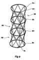
- FIG. 8shows an embodiment of a stacked stent according to this invention
- FIG. 9shows an embodiment of this invention used as a stent on the end of a leg of a bifurcated stent graft
- FIG. 10shows a perspective view of a alternative embodiment of the invention.
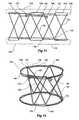
- FIG. 11shows a developed view of a further alternative embodiment of the invention.
- FIG. 12shows a perspective view of the alternative embodiment of the invention shown in FIG. 11 ;
- FIG. 13shows a perspective view of the alternative embodiment of the invention.
- FIG. 14shows a perspective view of the further embodiment of the invention.
- the stent 1comprises a first resilient ring assembly 3 and a second resilient ring assembly 4 spaced (preferably parallel) to and axially away from the first ring assembly 3 and a number of zig zag struts 5 between the first resilient ring assembly 3 and the second resilient ring assembly 4 .
- the first and second resilient ring assemblies and the strutscomprise a metallic wire.
- metal or metal alloy materialsare preferred other resilient materials such as polymers, carbon fibres and other biocompatible materials are also contemplated.
- the first ring assembly 3commences at a loop 7 of the wire and is formed from two circles or turns of wire 9 and then at 11 there is a bend and the wire is angled in a first strut 13 extending to a bend 15 adjacent the second ring assembly 4 and then a further angled strut 17 to a bend 19 adjacent the first ring assembly 3 .
- Consecutive angled struts and bendsextend around the periphery of the ring assembly 3 and the ring assembly 4 from the bend 19 until bend 21 adjacent to the bend 11 where there is an axial strut 23 extending to the second ring assembly 4 and a bend 25 .
- angled strut 27which extends to the first ring assembly 3 where there is a bend 29 and a subsequent angled strut 31 .
- Subsequent angled struts and bendsextend around the periphery of the second ring assembly 4 and first the ring assembly 3 from strut 31 to a bend 33 adjacent to bend 25 where the wire extends to a first circle or turn 35 of the ring assembly 4 and then to a second turn 37 of the ring assembly 4 to finally terminate in a loop 39 of the wire.
- the wire in this embodimentis preferably nitinol and has a diameter of 150 microns and the stent has a diameter of 8 mm and a length of 9 mm.
- FIG. 2shows an embodiment of the stent shown in FIG. 1 with a biocompatible graft material lining.
- the graft material 40is retained by stitching 41 to the first ring assembly 3 and by stitching 42 to the second ring assembly 4 .
- Stitching 44is also provided to retain the graft material into a cylindrical shape where the struts cross between the first and second rings.
- the graft materialmay be Dacron, ThoralonTM material, nylon or any other suitable material such as collagenous extracellular matrix (ECM) material including small intestine submucosa, which is commercially available from Cook Biotech, West Lafayette, Ind., U.S.A.
- ECMextracellular matrix
- a biocompatible graft material covering 50is provided on the outside of the stent 1 with the material 50 sewn to and retained onto the first ring assembly 3 by stitching 51 , onto the second ring assembly 4 by stitching 52 and to the struts by stitching 53 .
- FIG. 4shows a further embodiment of a stent according to this invention.
- the first ring 60 and the second ring 61 of the stentare formed as a wavy ring with the waves extending axially so that there are alternate troughs 62 and crests 63 .
- the crests 63correspond substantially with the bends 64 between struts 65 of the zig zag portion 66 of the stent.
- the apices 62extend towards the ring 61 .
- the wavy ringscan be formed so that their rest diameter is substantially the desired final diameter of the stent.
- FIG. 5shows a still further embodiment of a stent according to this invention.
- the stenthas a two-circle or turn ring 70 of wire at its upper end, a two-circle or turn ring 72 of wire at its lower end and a number of zig zag struts 74 of wire between the rings 70 and 72 .
- all of the pairs of strutscommence at the ring 70 and after six pairs of zig zag struts, a single strut 76 extends to the ring 72 to complete the stent with the two turns of the second ring.
- the bends 73incorporate the ring 70 within the acute angle of the bend and the bends 75 incorporate the ring 72 within the acute angle of the bend.
- FIG. 6shows a plan view of the stent shown in FIG. 1 and it will be noted that the stent in plan view is substantially cylindrical and the ring 3 and the termination loops 7 and 39 can be seen.
- FIG. 7shows a side elevation view of the stent similar to that shown in FIG. 1 except that at the apex of each of the bends there is a helix arrangement 38 to give more resilience to each bend. It will be noted that the zig zag struts 5 provide an essentially cylindrical peripheral surface to the stent.
- FIG. 8shows a further embodiment of a stent in which there is a first ring 80 , a second ring 82 , a third ring 84 and a fourth ring 86 . Between each pair of rings there is a zig zag strut portion 88 .
- the stent according to this embodiment of the inventioncan be made from a single length of wire commencing with the loop 89 on the ring 80 and terminating with the loop 90 on the ring 86 .
- a substantially cylindrical elongated stentcan be formed without welds which could introduce weakness into the stent.
- FIG. 9shows an arrangement of bifurcated or branched stent graft according to this invention using a stent of the present invention.
- the stent graftcomprises a tubular main body 100 with well-known Gianturco type zigzag Z stents 102 along its length. Extending from a bifurcation 103 in the tubular body 100 is a side arm 104 .
- the side arm 104has a Gianturco type zig zag Z stent 105 and terminates in a ring stent 106 of the type disclosed in this invention.
- the use of the stent graft 106 on the side arm 104provides a diametrically stable arm into which an extension leg or arm can be inserted with good reliability for sealing into the side arm either using a covered self expanding stent or a covered balloon expandable stent.
- FIG. 10shows a perspective view of a still further embodiment of a stent according to this invention.
- the stenthas two circles or turns of wire 109 starting with a loop 111 to form a ring assembly 110 of wire at its upper end and a number of zig zag struts 112 of wire extending axially from the circumference of the rings 110 .
- all of the pairs of struts 112commence at the ring 110 and after six pairs of zig zag struts 112 a partial turn of wire 114 follows the ring 110 and terminates in a loop 116 to complete the stent.
- the stent of this embodimentmay be particularly useful for mounting onto a leg or arm of a stent graft to provide dimensional stability at its end.
- FIG. 11 and FIG. 12show a further alternative embodiment of the invention.
- FIG. 11shows a stylised or developed view of a stent according to an embodiment of the invention laid out flat to show the continuous strand of Nitinol or stainless steel formed into the rings and struts.
- FIG. 12shows the stent of FIG. 11 in a perspective view. In this embodiment there are in effect five sets of bends at each ring of the stent but there may be other odd numbers of sets of bends such as seven or nine.
- the stent 120 of this embodimenthas a single continuous length of material such as wire starting at loop 122 and forming a first ring 124 to a bend 126 and then a first angled strut 128 to another bend 130 and then into a second ring 132 which is spaced apart, essentially coaxial with and parallel to the first ring 124 .
- the second ring 132has one and one fifth turns and then a bend 134 and then an angled strut 136 to the first ring and a bend 138 .
- Beyond the bend 138there is a circumferential peripheral portion 140 essentially parallel and adjacent to the first ring 124 to a further bend 142 .
- FIG. 13shows a perspective view of the alternative embodiment of the invention.
- the stent 150is formed from a tube or cannula of metal or other material and can be, for instance, laser cut from the tube or cannula in a known manner.
- the material of the stent 150is resilient so that the stent is deformable.
- the stent 150includes a first resilient ring 152 and a second resilient ring 153 spaced apart axially from the first ring 152 , and a plurality of diagonal or zig zag struts 154 around the periphery and between the first and second resilient rings.
- the struts 154meet in between the first and second rings at 155 but in an alternative embodiment the struts may not cross between the first and second rings.
- FIG. 13shows a squat ring stent according to the invention, that is, the height is about half the diameter.
- FIG. 14shows a perspective view of the alternative embodiment of the invention.
- the ring stentis formed from a tube or cannula of metal or other material and can be, for instance, laser cut from the tube or cannula in a known manner.
- the material of the stent 160is resilient so that the stent is deformable.
- the ring stentincludes a first resilient ring 162 and a second resilient ring 163 spaced apart axially from the first ring 162 , and a plurality of diagonal or zig zag struts 164 around the periphery and between the first and second resilient rings.
- the strutscross between the first ring 162 and second ring 163 to form junctions 165 .
- the ring stentis tall rather than squat, that is, the height is about twice the diameter.
Landscapes
- Health & Medical Sciences (AREA)
- Engineering & Computer Science (AREA)
- Biomedical Technology (AREA)
- Heart & Thoracic Surgery (AREA)
- Oral & Maxillofacial Surgery (AREA)
- Transplantation (AREA)
- Cardiology (AREA)
- Vascular Medicine (AREA)
- Life Sciences & Earth Sciences (AREA)
- Animal Behavior & Ethology (AREA)
- General Health & Medical Sciences (AREA)
- Public Health (AREA)
- Veterinary Medicine (AREA)
- Pulmonology (AREA)
- Gastroenterology & Hepatology (AREA)
- Prostheses (AREA)
Abstract
Description
Claims (4)
Priority Applications (3)
| Application Number | Priority Date | Filing Date | Title |
|---|---|---|---|
| US10/962,638US8043357B2 (en) | 2003-10-10 | 2004-10-12 | Ring stent |
| US13/278,790US9050181B2 (en) | 2003-10-10 | 2011-10-21 | Ring stent |
| US14/733,302US9775731B2 (en) | 2003-10-10 | 2015-06-08 | Ring stent |
Applications Claiming Priority (2)
| Application Number | Priority Date | Filing Date | Title |
|---|---|---|---|
| US51024203P | 2003-10-10 | 2003-10-10 | |
| US10/962,638US8043357B2 (en) | 2003-10-10 | 2004-10-12 | Ring stent |
Related Child Applications (1)
| Application Number | Title | Priority Date | Filing Date |
|---|---|---|---|
| US13/278,790ContinuationUS9050181B2 (en) | 2003-10-10 | 2011-10-21 | Ring stent |
Publications (2)
| Publication Number | Publication Date |
|---|---|
| US20050131525A1 US20050131525A1 (en) | 2005-06-16 |
| US8043357B2true US8043357B2 (en) | 2011-10-25 |
Family
ID=34657006
Family Applications (3)
| Application Number | Title | Priority Date | Filing Date |
|---|---|---|---|
| US10/962,638Expired - LifetimeUS8043357B2 (en) | 2003-10-10 | 2004-10-12 | Ring stent |
| US13/278,790Expired - LifetimeUS9050181B2 (en) | 2003-10-10 | 2011-10-21 | Ring stent |
| US14/733,302Expired - LifetimeUS9775731B2 (en) | 2003-10-10 | 2015-06-08 | Ring stent |
Family Applications After (2)
| Application Number | Title | Priority Date | Filing Date |
|---|---|---|---|
| US13/278,790Expired - LifetimeUS9050181B2 (en) | 2003-10-10 | 2011-10-21 | Ring stent |
| US14/733,302Expired - LifetimeUS9775731B2 (en) | 2003-10-10 | 2015-06-08 | Ring stent |
Country Status (1)
| Country | Link |
|---|---|
| US (3) | US8043357B2 (en) |
Cited By (41)
| Publication number | Priority date | Publication date | Assignee | Title |
|---|---|---|---|---|
| US20130289703A1 (en)* | 2012-04-27 | 2013-10-31 | Medtronic Vascular, Inc. | Ring on a closed web stent-graft for use in tip capture |
| US8984733B2 (en) | 2013-02-05 | 2015-03-24 | Artventive Medical Group, Inc. | Bodily lumen occlusion |
| US9017351B2 (en) | 2010-06-29 | 2015-04-28 | Artventive Medical Group, Inc. | Reducing flow through a tubular structure |
| US9095344B2 (en) | 2013-02-05 | 2015-08-04 | Artventive Medical Group, Inc. | Methods and apparatuses for blood vessel occlusion |
| US9138335B2 (en) | 2006-07-31 | 2015-09-22 | Syntheon Cardiology, Llc | Surgical implant devices and methods for their manufacture and use |
| US9149277B2 (en) | 2010-10-18 | 2015-10-06 | Artventive Medical Group, Inc. | Expandable device delivery |
| US9247942B2 (en) | 2010-06-29 | 2016-02-02 | Artventive Medical Group, Inc. | Reversible tubal contraceptive device |
| US9408607B2 (en) | 2009-07-02 | 2016-08-09 | Edwards Lifesciences Cardiaq Llc | Surgical implant devices and methods for their manufacture and use |
| US9566178B2 (en) | 2010-06-24 | 2017-02-14 | Edwards Lifesciences Cardiaq Llc | Actively controllable stent, stent graft, heart valve and method of controlling same |
| US9585743B2 (en) | 2006-07-31 | 2017-03-07 | Edwards Lifesciences Cardiaq Llc | Surgical implant devices and methods for their manufacture and use |
| US9636116B2 (en) | 2013-06-14 | 2017-05-02 | Artventive Medical Group, Inc. | Implantable luminal devices |
| US9737306B2 (en) | 2013-06-14 | 2017-08-22 | Artventive Medical Group, Inc. | Implantable luminal devices |
| US9737308B2 (en) | 2013-06-14 | 2017-08-22 | Artventive Medical Group, Inc. | Catheter-assisted tumor treatment |
| US9814611B2 (en) | 2007-07-31 | 2017-11-14 | Edwards Lifesciences Cardiaq Llc | Actively controllable stent, stent graft, heart valve and method of controlling same |
| US9827093B2 (en) | 2011-10-21 | 2017-11-28 | Edwards Lifesciences Cardiaq Llc | Actively controllable stent, stent graft, heart valve and method of controlling same |
| US9918823B2 (en) | 2009-06-10 | 2018-03-20 | Cook Medical Technologies Llc | Reinforcing ring |
| US10076428B2 (en) | 2016-08-25 | 2018-09-18 | DePuy Synthes Products, Inc. | Expansion ring for a braided stent |
| US10117762B2 (en) | 2007-12-12 | 2018-11-06 | Intact Vascular, Inc. | Endoluminal device and method |
| US10137013B2 (en) | 2010-05-29 | 2018-11-27 | Intact Vascular, Inc. | Endoluminal device and method |
| US10149968B2 (en) | 2013-06-14 | 2018-12-11 | Artventive Medical Group, Inc. | Catheter-assisted tumor treatment |
| US10166127B2 (en) | 2007-12-12 | 2019-01-01 | Intact Vascular, Inc. | Endoluminal device and method |
| US10245167B2 (en) | 2015-01-29 | 2019-04-02 | Intact Vascular, Inc. | Delivery device and method of delivery |
| US10271973B2 (en) | 2011-06-03 | 2019-04-30 | Intact Vascular, Inc. | Endovascular implant |
| US10278839B2 (en) | 2007-12-12 | 2019-05-07 | Intact Vascular, Inc. | Endovascular impant |
| US10299945B2 (en) | 2007-12-12 | 2019-05-28 | Intact Vascular, Inc. | Method of treating atherosclerotic occlusive disease |
| US10363043B2 (en) | 2014-05-01 | 2019-07-30 | Artventive Medical Group, Inc. | Treatment of incompetent vessels |
| US10660771B2 (en) | 2007-12-12 | 2020-05-26 | Intact Vacsular, Inc. | Deployment device for placement of multiple intraluminal surgical staples |
| WO2020163542A1 (en) | 2019-02-06 | 2020-08-13 | Seshadri Raju | Venous and arterial application of the unitary stent & balloon |
| US10799374B2 (en) | 2007-12-12 | 2020-10-13 | Intact Vascular, Inc. | Device and method for tacking plaque to blood vessel wall |
| US10813644B2 (en) | 2016-04-01 | 2020-10-27 | Artventive Medical Group, Inc. | Occlusive implant and delivery system |
| US10821010B2 (en) | 2014-08-27 | 2020-11-03 | DePuy Synthes Products, Inc. | Method of making a multi-strand implant with enhanced radiopacity |
| US10893963B2 (en) | 2018-08-06 | 2021-01-19 | DePuy Synthes Products, Inc. | Stent delivery with expansion assisting delivery wire |
| US10898356B2 (en) | 2015-01-29 | 2021-01-26 | Intact Vascular, Inc. | Delivery device and method of delivery |
| US10993824B2 (en) | 2016-01-01 | 2021-05-04 | Intact Vascular, Inc. | Delivery device and method of delivery |
| US11039944B2 (en) | 2018-12-27 | 2021-06-22 | DePuy Synthes Products, Inc. | Braided stent system with one or more expansion rings |
| US11090175B2 (en) | 2018-07-30 | 2021-08-17 | DePuy Synthes Products, Inc. | Systems and methods of manufacturing and using an expansion ring |
| US11129738B2 (en) | 2016-09-30 | 2021-09-28 | DePuy Synthes Products, Inc. | Self-expanding device delivery apparatus with dual function bump |
| US11357648B2 (en) | 2018-08-06 | 2022-06-14 | DePuy Synthes Products, Inc. | Systems and methods of using a braided implant |
| US11452623B2 (en) | 2013-03-13 | 2022-09-27 | DePuy Synthes Products, Inc. | Braided stent with expansion ring and method of delivery |
| US11559386B2 (en) | 2017-07-07 | 2023-01-24 | Endologix Llc | Endovascular graft systems and methods for deployment in main and branch arteries |
| US11660218B2 (en) | 2017-07-26 | 2023-05-30 | Intact Vascular, Inc. | Delivery device and method of delivery |
Families Citing this family (28)
| Publication number | Priority date | Publication date | Assignee | Title |
|---|---|---|---|---|
| US8038708B2 (en)* | 2001-02-05 | 2011-10-18 | Cook Medical Technologies Llc | Implantable device with remodelable material and covering material |
| US20070027535A1 (en)* | 2005-07-28 | 2007-02-01 | Cook Incorporated | Implantable thromboresistant valve |
| US9125733B2 (en)* | 2003-01-14 | 2015-09-08 | The Cleveland Clinic Foundation | Branched vessel endoluminal device |
| EP3103422A1 (en) | 2003-03-14 | 2016-12-14 | Intersect ENT, Inc. | Sinus delivery of sustained release therapeutics |
| US9545300B2 (en)* | 2004-12-22 | 2017-01-17 | W. L. Gore & Associates, Inc. | Filament-wound implantable devices |
| JP5247428B2 (en) | 2005-04-04 | 2013-07-24 | インターセクト エント, インコーポレイテッド | Apparatus and method for treating sinus symptoms |
| EP1983933B1 (en)* | 2006-02-13 | 2013-01-23 | William A. Cook Australia Pty. Ltd. | Side branch stent graft construction |
| US9155641B2 (en)* | 2006-03-09 | 2015-10-13 | Cook Medical Technologies Llc | Expandable stent grafts |
| AU2007240703C1 (en) | 2006-04-19 | 2012-06-14 | Cleveland Clinic Foundation | Twin bifurcated stent graft |
| US8535707B2 (en) | 2006-07-10 | 2013-09-17 | Intersect Ent, Inc. | Devices and methods for delivering active agents to the osteomeatal complex |
| WO2008094504A1 (en)* | 2007-01-29 | 2008-08-07 | Cook Incorporated | Medical prosthesis and method of production |
| DE102007025921A1 (en)* | 2007-06-02 | 2008-12-04 | Biotronik Vi Patent Ag | Medical implant, in particular stent |
| EP3791826B1 (en) | 2007-12-18 | 2025-01-29 | Intersect ENT, Inc. | Self-expanding devices |
| AU2009276505B2 (en) | 2008-08-01 | 2015-04-23 | Intersect Ent, Inc. | Methods and devices for crimping self-expanding devices |
| EP2754463B1 (en) | 2009-05-15 | 2016-06-22 | Intersect ENT, Inc. | Expandable devices |
| GB2472603B (en)* | 2009-08-11 | 2011-12-14 | Cook Medical Technologies Llc | Implantable medical device |
| AU2014236729B2 (en) | 2013-03-14 | 2018-11-22 | Intersect Ent, Inc. | Systems, devices, and method for treating a sinus condition |
| US20150257908A1 (en)* | 2014-03-14 | 2015-09-17 | The Board Of Trustees Of The Leland Stanford Junior University | Indwelling body lumen expander |
| JP2018504209A (en) | 2015-01-22 | 2018-02-15 | インターセクト エント, インコーポレイテッド | Drug coated balloon |
| AU2017371223B2 (en) | 2016-12-09 | 2023-04-27 | Zenflow, Inc. | Systems, devices, and methods for the accurate deployment of an implant in the prostatic urethra |
| CN110833469B (en)* | 2018-08-17 | 2023-06-20 | 先健科技(深圳)有限公司 | Tectorial membrane support |
| US11109939B2 (en) | 2019-06-14 | 2021-09-07 | DePuy Synthes Products, Inc. | Intravascular devices with radiopaque body markers |
| US12403291B2 (en) | 2019-08-30 | 2025-09-02 | Intersect Ent, Inc. | Submucosal bioresorbable drug eluting platform |
| US11890213B2 (en) | 2019-11-19 | 2024-02-06 | Zenflow, Inc. | Systems, devices, and methods for the accurate deployment and imaging of an implant in the prostatic urethra |
| CN111297514B (en)* | 2020-03-19 | 2023-06-02 | 南京普微森医疗科技有限公司 | Intracranial tectorial membrane support structure for neurosurgery |
| CN113476178B (en)* | 2021-07-01 | 2025-06-10 | 上海创心医学科技有限公司 | Vascular stent |
| CN113476175B (en)* | 2021-07-01 | 2025-06-10 | 上海创心医学科技有限公司 | Vascular stent |
| CN113476176B (en)* | 2021-07-01 | 2025-06-10 | 上海创心医学科技有限公司 | Vascular stent |
Citations (16)
| Publication number | Priority date | Publication date | Assignee | Title |
|---|---|---|---|---|
| US4907336A (en)* | 1987-03-13 | 1990-03-13 | Cook Incorporated | Method of making an endovascular stent and delivery system |
| US5242452A (en)* | 1991-10-11 | 1993-09-07 | Kanji Inoue | Device for collapsing an appliance collapsible for insertion into human organs |
| US5282824A (en)* | 1990-10-09 | 1994-02-01 | Cook, Incorporated | Percutaneous stent assembly |
| US5354308A (en)* | 1992-05-01 | 1994-10-11 | Beth Israel Hospital Association | Metal wire stent |
| US5387235A (en) | 1991-10-25 | 1995-02-07 | Cook Incorporated | Expandable transluminal graft prosthesis for repair of aneurysm |
| US5720776A (en) | 1991-10-25 | 1998-02-24 | Cook Incorporated | Barb and expandable transluminal graft prosthesis for repair of aneurysm |
| WO1998053761A1 (en) | 1997-05-26 | 1998-12-03 | William A. Cook Australia Pty. Ltd. | A prosthesis and a method and means of deploying a prosthesis |
| US6206931B1 (en) | 1996-08-23 | 2001-03-27 | Cook Incorporated | Graft prosthesis materials |
| US20010010015A1 (en)* | 1999-10-05 | 2001-07-26 | Hijlkema Lukas J. | Flexible endoluminal stent and process of repairing a body lumen |
| US6383216B1 (en)* | 1992-08-06 | 2002-05-07 | William Cook Europe A/S | Implantable self expanding prosthetic device |
| US20030033003A1 (en)* | 2001-08-13 | 2003-02-13 | Harrison William James | Apparatus and method for decreasing stent gap size |
| US6524335B1 (en) | 1997-12-10 | 2003-02-25 | William A. Cook Australia Pty. Ltd. | Endoluminal aortic stents |
| US6616675B1 (en)* | 1996-02-02 | 2003-09-09 | Transvascular, Inc. | Methods and apparatus for connecting openings formed in adjacent blood vessels or other anatomical structures |
| US6939370B2 (en) | 2002-06-28 | 2005-09-06 | Cook Incorporated | Thoracic aortic stent graft deployment device |
| US6974471B2 (en) | 2001-10-26 | 2005-12-13 | Cook Incorporated | Prostheses for curved lumens |
| US20060136031A1 (en)* | 2002-10-31 | 2006-06-22 | Richard Gallo | Balloon deployable stent and method of using the same |
Family Cites Families (22)
| Publication number | Priority date | Publication date | Assignee | Title |
|---|---|---|---|---|
| US4902508A (en) | 1988-07-11 | 1990-02-20 | Purdue Research Foundation | Tissue graft composition |
| US4856516A (en)* | 1989-01-09 | 1989-08-15 | Cordis Corporation | Endovascular stent apparatus and method |
| US5035706A (en) | 1989-10-17 | 1991-07-30 | Cook Incorporated | Percutaneous stent and method for retrieval thereof |
| US5397351A (en)* | 1991-05-13 | 1995-03-14 | Pavcnik; Dusan | Prosthetic valve for percutaneous insertion |
| US5290305A (en)* | 1991-10-11 | 1994-03-01 | Kanji Inoue | Appliance collapsible for insertion into human organs and capable of resilient restoration |
| US5554181A (en)* | 1994-05-04 | 1996-09-10 | Regents Of The University Of Minnesota | Stent |
| AU3139295A (en) | 1994-07-22 | 1996-02-22 | Apple Computer, Inc. | Method and system for the placement of texture on three-dimensional objects |
| IT1274098B (en)* | 1994-11-08 | 1997-07-15 | Xtrode Srl | CORONARY ENDOPROTESIS |
| US5711969A (en) | 1995-04-07 | 1998-01-27 | Purdue Research Foundation | Large area submucosal tissue graft constructs |
| US5776161A (en)* | 1995-10-16 | 1998-07-07 | Instent, Inc. | Medical stents, apparatus and method for making same |
| US6287336B1 (en)* | 1995-10-16 | 2001-09-11 | Medtronic, Inc. | Variable flexibility stent |
| US5755791A (en) | 1996-04-05 | 1998-05-26 | Purdue Research Foundation | Perforated submucosal tissue graft constructs |
| US6635080B1 (en)* | 1997-06-19 | 2003-10-21 | Vascutek Limited | Prosthesis for repair of body passages |
| US6187036B1 (en)* | 1998-12-11 | 2001-02-13 | Endologix, Inc. | Endoluminal vascular prosthesis |
| US6245101B1 (en)* | 1999-05-03 | 2001-06-12 | William J. Drasler | Intravascular hinge stent |
| AUPR961701A0 (en) | 2001-12-19 | 2002-01-24 | Cook Incorporated | Improving graft adhesion |
| DE60302459T2 (en) | 2002-05-29 | 2006-08-03 | Cook Inc., Bloomington | TRIGGER WIRE SYSTEM FOR A PROSTHESIS PLASMA DEVICE |
| CA2487462C (en) | 2002-06-26 | 2012-05-15 | Cook Incorporated | Stent-graft fastening |
| US7232459B2 (en) | 2002-06-28 | 2007-06-19 | Cook Incorporated | Thoracic aortic aneurysm stent graft |
| AU2003258337A1 (en) | 2002-08-23 | 2004-03-11 | Cook Incorporated | Asymmetric stent graft attachment |
| DK1545396T3 (en) | 2002-08-23 | 2009-03-02 | Cook William A Australia | composite prosthesis |
| US6966923B2 (en)* | 2003-01-24 | 2005-11-22 | Medtronic Vascular, Inc. | Stent delivery system and low profile stent |
- 2004
- 2004-10-12USUS10/962,638patent/US8043357B2/ennot_activeExpired - Lifetime
- 2011
- 2011-10-21USUS13/278,790patent/US9050181B2/ennot_activeExpired - Lifetime
- 2015
- 2015-06-08USUS14/733,302patent/US9775731B2/ennot_activeExpired - Lifetime
Patent Citations (16)
| Publication number | Priority date | Publication date | Assignee | Title |
|---|---|---|---|---|
| US4907336A (en)* | 1987-03-13 | 1990-03-13 | Cook Incorporated | Method of making an endovascular stent and delivery system |
| US5282824A (en)* | 1990-10-09 | 1994-02-01 | Cook, Incorporated | Percutaneous stent assembly |
| US5242452A (en)* | 1991-10-11 | 1993-09-07 | Kanji Inoue | Device for collapsing an appliance collapsible for insertion into human organs |
| US5387235A (en) | 1991-10-25 | 1995-02-07 | Cook Incorporated | Expandable transluminal graft prosthesis for repair of aneurysm |
| US5720776A (en) | 1991-10-25 | 1998-02-24 | Cook Incorporated | Barb and expandable transluminal graft prosthesis for repair of aneurysm |
| US5354308A (en)* | 1992-05-01 | 1994-10-11 | Beth Israel Hospital Association | Metal wire stent |
| US6383216B1 (en)* | 1992-08-06 | 2002-05-07 | William Cook Europe A/S | Implantable self expanding prosthetic device |
| US6616675B1 (en)* | 1996-02-02 | 2003-09-09 | Transvascular, Inc. | Methods and apparatus for connecting openings formed in adjacent blood vessels or other anatomical structures |
| US6206931B1 (en) | 1996-08-23 | 2001-03-27 | Cook Incorporated | Graft prosthesis materials |
| WO1998053761A1 (en) | 1997-05-26 | 1998-12-03 | William A. Cook Australia Pty. Ltd. | A prosthesis and a method and means of deploying a prosthesis |
| US6524335B1 (en) | 1997-12-10 | 2003-02-25 | William A. Cook Australia Pty. Ltd. | Endoluminal aortic stents |
| US20010010015A1 (en)* | 1999-10-05 | 2001-07-26 | Hijlkema Lukas J. | Flexible endoluminal stent and process of repairing a body lumen |
| US20030033003A1 (en)* | 2001-08-13 | 2003-02-13 | Harrison William James | Apparatus and method for decreasing stent gap size |
| US6974471B2 (en) | 2001-10-26 | 2005-12-13 | Cook Incorporated | Prostheses for curved lumens |
| US6939370B2 (en) | 2002-06-28 | 2005-09-06 | Cook Incorporated | Thoracic aortic stent graft deployment device |
| US20060136031A1 (en)* | 2002-10-31 | 2006-06-22 | Richard Gallo | Balloon deployable stent and method of using the same |
Non-Patent Citations (6)
| Title |
|---|
| U.S. Patent Application Publication No. 2003/0120332; Hartley : Jun. 2003. |
| U.S. Patent Application Publication No. 2003/0233140; Hartley et al.; Dec. 2003. |
| U.S. Patent Application Publication No. 2004/0054396; Hartley et al.; Mar. 2004. |
| U.S. Patent Application Publication No. 2004/0073289; Hartley; Apr. 2004. |
| U.S. Patent Application Publication No. 2004/0082990; Hartley; Apr. 2004. |
| U.S. Patent Application Publication No. 2004/0106978; Greenberg et al.; Jun. 2004. |
Cited By (63)
| Publication number | Priority date | Publication date | Assignee | Title |
|---|---|---|---|---|
| US9585743B2 (en) | 2006-07-31 | 2017-03-07 | Edwards Lifesciences Cardiaq Llc | Surgical implant devices and methods for their manufacture and use |
| US9138335B2 (en) | 2006-07-31 | 2015-09-22 | Syntheon Cardiology, Llc | Surgical implant devices and methods for their manufacture and use |
| US9827125B2 (en) | 2006-07-31 | 2017-11-28 | Edwards Lifesciences Cardiaq Llc | Sealable endovascular implants and methods for their use |
| US9814611B2 (en) | 2007-07-31 | 2017-11-14 | Edwards Lifesciences Cardiaq Llc | Actively controllable stent, stent graft, heart valve and method of controlling same |
| US10835395B2 (en) | 2007-12-12 | 2020-11-17 | Intact Vascular, Inc. | Method of treating atherosclerotic occlusive disease |
| US10799374B2 (en) | 2007-12-12 | 2020-10-13 | Intact Vascular, Inc. | Device and method for tacking plaque to blood vessel wall |
| US10660771B2 (en) | 2007-12-12 | 2020-05-26 | Intact Vacsular, Inc. | Deployment device for placement of multiple intraluminal surgical staples |
| US10299945B2 (en) | 2007-12-12 | 2019-05-28 | Intact Vascular, Inc. | Method of treating atherosclerotic occlusive disease |
| US10278839B2 (en) | 2007-12-12 | 2019-05-07 | Intact Vascular, Inc. | Endovascular impant |
| US10166127B2 (en) | 2007-12-12 | 2019-01-01 | Intact Vascular, Inc. | Endoluminal device and method |
| US10117762B2 (en) | 2007-12-12 | 2018-11-06 | Intact Vascular, Inc. | Endoluminal device and method |
| US9918823B2 (en) | 2009-06-10 | 2018-03-20 | Cook Medical Technologies Llc | Reinforcing ring |
| US10888443B2 (en) | 2009-06-11 | 2021-01-12 | Intact Vascular, Inc. | Device for holding plaque to blood vessel wall |
| US10779971B2 (en) | 2009-06-11 | 2020-09-22 | Intact Vascular, Inc. | Endovascular implant |
| US9408607B2 (en) | 2009-07-02 | 2016-08-09 | Edwards Lifesciences Cardiaq Llc | Surgical implant devices and methods for their manufacture and use |
| US10779968B2 (en) | 2010-05-29 | 2020-09-22 | Intact Vascular, Inc. | Endoluminal device and method |
| US10137013B2 (en) | 2010-05-29 | 2018-11-27 | Intact Vascular, Inc. | Endoluminal device and method |
| US9566178B2 (en) | 2010-06-24 | 2017-02-14 | Edwards Lifesciences Cardiaq Llc | Actively controllable stent, stent graft, heart valve and method of controlling same |
| US9247942B2 (en) | 2010-06-29 | 2016-02-02 | Artventive Medical Group, Inc. | Reversible tubal contraceptive device |
| US9017351B2 (en) | 2010-06-29 | 2015-04-28 | Artventive Medical Group, Inc. | Reducing flow through a tubular structure |
| US9451965B2 (en) | 2010-06-29 | 2016-09-27 | Artventive Medical Group, Inc. | Reducing flow through a tubular structure |
| US9149277B2 (en) | 2010-10-18 | 2015-10-06 | Artventive Medical Group, Inc. | Expandable device delivery |
| US10390977B2 (en) | 2011-06-03 | 2019-08-27 | Intact Vascular, Inc. | Endovascular implant |
| US10285831B2 (en) | 2011-06-03 | 2019-05-14 | Intact Vascular, Inc. | Endovascular implant |
| US10779969B2 (en) | 2011-06-03 | 2020-09-22 | Intact Vascular, Inc. | Endovascular implant and deployment devices |
| US10271973B2 (en) | 2011-06-03 | 2019-04-30 | Intact Vascular, Inc. | Endovascular implant |
| US9827093B2 (en) | 2011-10-21 | 2017-11-28 | Edwards Lifesciences Cardiaq Llc | Actively controllable stent, stent graft, heart valve and method of controlling same |
| US8882828B2 (en)* | 2012-04-27 | 2014-11-11 | Medtronic Vascular, Inc. | Ring on a closed web stent-graft for use in tip capture |
| US20130289703A1 (en)* | 2012-04-27 | 2013-10-31 | Medtronic Vascular, Inc. | Ring on a closed web stent-graft for use in tip capture |
| US10335265B2 (en) | 2012-04-27 | 2019-07-02 | Medtronic Vascular, Inc. | Ring on a closed web stent-graft for use in tip capture |
| US9107669B2 (en) | 2013-02-05 | 2015-08-18 | Artventive Medical Group, Inc. | Blood vessel occlusion |
| US9095344B2 (en) | 2013-02-05 | 2015-08-04 | Artventive Medical Group, Inc. | Methods and apparatuses for blood vessel occlusion |
| US8984733B2 (en) | 2013-02-05 | 2015-03-24 | Artventive Medical Group, Inc. | Bodily lumen occlusion |
| US9737307B2 (en) | 2013-02-05 | 2017-08-22 | Artventive Medical Group, Inc. | Blood vessel occlusion |
| US10004513B2 (en) | 2013-02-05 | 2018-06-26 | Artventive Medical Group, Inc. | Bodily lumen occlusion |
| US11529249B2 (en) | 2013-03-13 | 2022-12-20 | DePuy Synthes Products, Inc. | Braided stent with expansion ring and method of delivery |
| US11452623B2 (en) | 2013-03-13 | 2022-09-27 | DePuy Synthes Products, Inc. | Braided stent with expansion ring and method of delivery |
| US10149968B2 (en) | 2013-06-14 | 2018-12-11 | Artventive Medical Group, Inc. | Catheter-assisted tumor treatment |
| US9737308B2 (en) | 2013-06-14 | 2017-08-22 | Artventive Medical Group, Inc. | Catheter-assisted tumor treatment |
| US9636116B2 (en) | 2013-06-14 | 2017-05-02 | Artventive Medical Group, Inc. | Implantable luminal devices |
| US9737306B2 (en) | 2013-06-14 | 2017-08-22 | Artventive Medical Group, Inc. | Implantable luminal devices |
| US10441290B2 (en) | 2013-06-14 | 2019-10-15 | Artventive Medical Group, Inc. | Implantable luminal devices |
| US10363043B2 (en) | 2014-05-01 | 2019-07-30 | Artventive Medical Group, Inc. | Treatment of incompetent vessels |
| US11224438B2 (en) | 2014-05-01 | 2022-01-18 | Artventive Medical Group, Inc. | Treatment of incompetent vessels |
| US10821010B2 (en) | 2014-08-27 | 2020-11-03 | DePuy Synthes Products, Inc. | Method of making a multi-strand implant with enhanced radiopacity |
| US10245167B2 (en) | 2015-01-29 | 2019-04-02 | Intact Vascular, Inc. | Delivery device and method of delivery |
| US11304836B2 (en) | 2015-01-29 | 2022-04-19 | Intact Vascular, Inc. | Delivery device and method of delivery |
| US10898356B2 (en) | 2015-01-29 | 2021-01-26 | Intact Vascular, Inc. | Delivery device and method of delivery |
| US10993824B2 (en) | 2016-01-01 | 2021-05-04 | Intact Vascular, Inc. | Delivery device and method of delivery |
| US10813644B2 (en) | 2016-04-01 | 2020-10-27 | Artventive Medical Group, Inc. | Occlusive implant and delivery system |
| US10821008B2 (en) | 2016-08-25 | 2020-11-03 | DePuy Synthes Products, Inc. | Expansion ring for a braided stent |
| US10076428B2 (en) | 2016-08-25 | 2018-09-18 | DePuy Synthes Products, Inc. | Expansion ring for a braided stent |
| US12064363B2 (en) | 2016-09-30 | 2024-08-20 | DePuy Synthes Products, Inc. | Self-expanding device delivery apparatus with dual function bump |
| US11129738B2 (en) | 2016-09-30 | 2021-09-28 | DePuy Synthes Products, Inc. | Self-expanding device delivery apparatus with dual function bump |
| US11559386B2 (en) | 2017-07-07 | 2023-01-24 | Endologix Llc | Endovascular graft systems and methods for deployment in main and branch arteries |
| US11660218B2 (en) | 2017-07-26 | 2023-05-30 | Intact Vascular, Inc. | Delivery device and method of delivery |
| US11497638B2 (en) | 2018-07-30 | 2022-11-15 | DePuy Synthes Products, Inc. | Systems and methods of manufacturing and using an expansion ring |
| US11090175B2 (en) | 2018-07-30 | 2021-08-17 | DePuy Synthes Products, Inc. | Systems and methods of manufacturing and using an expansion ring |
| US11357648B2 (en) | 2018-08-06 | 2022-06-14 | DePuy Synthes Products, Inc. | Systems and methods of using a braided implant |
| US10893963B2 (en) | 2018-08-06 | 2021-01-19 | DePuy Synthes Products, Inc. | Stent delivery with expansion assisting delivery wire |
| US12004977B2 (en) | 2018-08-06 | 2024-06-11 | DePuy Synthes Products, Inc. | Systems and methods of using a braided implant |
| US11039944B2 (en) | 2018-12-27 | 2021-06-22 | DePuy Synthes Products, Inc. | Braided stent system with one or more expansion rings |
| WO2020163542A1 (en) | 2019-02-06 | 2020-08-13 | Seshadri Raju | Venous and arterial application of the unitary stent & balloon |
Also Published As
| Publication number | Publication date |
|---|---|
| US20150265439A1 (en) | 2015-09-24 |
| US9775731B2 (en) | 2017-10-03 |
| US20120035710A1 (en) | 2012-02-09 |
| US20050131525A1 (en) | 2005-06-16 |
| US9050181B2 (en) | 2015-06-09 |
Similar Documents
| Publication | Publication Date | Title |
|---|---|---|
| US8043357B2 (en) | Ring stent | |
| EP1776066B1 (en) | Stent having arcuate struts | |
| US10195059B2 (en) | Composite stent graft | |
| US6860900B2 (en) | Stent and stent-graft for treating branched vessels | |
| US9060887B2 (en) | Fenestrated stent grafts | |
| US6361556B1 (en) | System and method for endovascular aneurysm repair in conjuction with vascular stabilization | |
| US7294147B2 (en) | Composite prosthesis | |
| US7905915B2 (en) | Z-stent with incorporated barbs | |
| JP4825665B2 (en) | Lumen device with enhanced mounting characteristics | |
| US6355056B1 (en) | Implantable intraluminal prosthesis | |
| US20090149946A1 (en) | Stent having at least one barb and methods of manufacture | |
| US20140135899A1 (en) | Asymmetric stent apparatus and method | |
| JP2003531674A (en) | Stent graft | |
| AU2005286730A1 (en) | Stent graft connection arrangement | |
| US20160184115A1 (en) | Support structures for prostheses with branching portions | |
| AU2018214103B1 (en) | A stent-graft | |
| EP1477134A2 (en) | Stent and stent-graft for treating branched vessels |
Legal Events
| Date | Code | Title | Description |
|---|---|---|---|
| AS | Assignment | Owner name:WILLIAM A. COOK AUSTRALIA PTY. LTD., AUSTRALIA Free format text:ASSIGNMENT OF ASSIGNORS INTEREST;ASSIGNOR:HARTLEY, DAVID ERNEST;REEL/FRAME:018430/0174 Effective date:20050110 Owner name:COOK INCORPORATED, INDIANA Free format text:ASSIGNMENT OF ASSIGNORS INTEREST;ASSIGNOR:HARTLEY, DAVID ERNEST;REEL/FRAME:018430/0174 Effective date:20050110 | |
| AS | Assignment | Owner name:COOK MEDICAL TECHNOLOGIES LLC, INDIANA Free format text:ASSIGNMENT OF ASSIGNORS INTEREST;ASSIGNOR:COOK INCORPORATED;REEL/FRAME:026737/0565 Effective date:20110810 | |
| STCF | Information on status: patent grant | Free format text:PATENTED CASE | |
| FPAY | Fee payment | Year of fee payment:4 | |
| AS | Assignment | Owner name:COOK MEDICAL TECHNOLOGIES LLC, INDIANA Free format text:ASSIGNMENT OF ASSIGNORS INTEREST;ASSIGNOR:WILLIAM A. COOK AUSTRALIA PTY. LTD.;REEL/FRAME:035555/0098 Effective date:20150501 | |
| MAFP | Maintenance fee payment | Free format text:PAYMENT OF MAINTENANCE FEE, 8TH YEAR, LARGE ENTITY (ORIGINAL EVENT CODE: M1552); ENTITY STATUS OF PATENT OWNER: LARGE ENTITY Year of fee payment:8 | |
| MAFP | Maintenance fee payment | Free format text:PAYMENT OF MAINTENANCE FEE, 12TH YEAR, LARGE ENTITY (ORIGINAL EVENT CODE: M1553); ENTITY STATUS OF PATENT OWNER: LARGE ENTITY Year of fee payment:12 | |
| AS | Assignment | Owner name:WILMINGTON TRUST, NATIONAL ASSOCIATION, AS COLLATERAL AGENT, DELAWARE Free format text:SECURITY INTEREST;ASSIGNOR:COOK MEDICAL TECHNOLOGIES LLC;REEL/FRAME:066700/0277 Effective date:20240227 |