US8043339B2 - Flexible member for use in a spinal column and method for making - Google Patents
Flexible member for use in a spinal column and method for makingDownload PDFInfo
- Publication number
- US8043339B2 US8043339B2US11/923,340US92334007AUS8043339B2US 8043339 B2US8043339 B2US 8043339B2US 92334007 AUS92334007 AUS 92334007AUS 8043339 B2US8043339 B2US 8043339B2
- Authority
- US
- United States
- Prior art keywords
- elastomeric member
- fabric layer
- inner elastomeric
- flexible member
- elasticity
- Prior art date
- Legal status (The legal status is an assumption and is not a legal conclusion. Google has not performed a legal analysis and makes no representation as to the accuracy of the status listed.)
- Active, expires
Links
- 238000000034methodMethods0.000titleabstractdescription24
- 239000004744fabricSubstances0.000claimsabstractdescription62
- 230000000087stabilizing effectEffects0.000claimsabstractdescription4
- 230000006641stabilisationEffects0.000claimsdescription11
- 238000011105stabilizationMethods0.000claimsdescription11
- 239000000835fiberSubstances0.000claimsdescription4
- 239000000463materialSubstances0.000description17
- 239000007943implantSubstances0.000description12
- 239000013536elastomeric materialSubstances0.000description10
- 229910001000nickel titaniumInorganic materials0.000description10
- HLXZNVUGXRDIFK-UHFFFAOYSA-Nnickel titaniumChemical compound[Ti].[Ti].[Ti].[Ti].[Ti].[Ti].[Ti].[Ti].[Ti].[Ti].[Ti].[Ni].[Ni].[Ni].[Ni].[Ni].[Ni].[Ni].[Ni].[Ni].[Ni].[Ni].[Ni].[Ni].[Ni]HLXZNVUGXRDIFK-UHFFFAOYSA-N0.000description10
- 208000037265diseases, disorders, signs and symptomsDiseases0.000description6
- 208000035475disorderDiseases0.000description5
- -1polypropylenePolymers0.000description5
- 238000004519manufacturing processMethods0.000description4
- 239000000243solutionSubstances0.000description4
- 230000006378damageEffects0.000description3
- 239000013013elastic materialSubstances0.000description3
- 230000004927fusionEffects0.000description3
- OKTJSMMVPCPJKN-UHFFFAOYSA-NCarbonChemical compound[C]OKTJSMMVPCPJKN-UHFFFAOYSA-N0.000description2
- 208000027418Wounds and injuryDiseases0.000description2
- 238000005452bendingMethods0.000description2
- 210000000988bone and boneAnatomy0.000description2
- 239000002131composite materialSubstances0.000description2
- 238000002513implantationMethods0.000description2
- 208000014674injuryDiseases0.000description2
- 230000000149penetrating effectEffects0.000description2
- 229920002635polyurethanePolymers0.000description2
- 239000004814polyurethaneSubstances0.000description2
- 210000001519tissueAnatomy0.000description2
- 238000012546transferMethods0.000description2
- 208000007623LordosisDiseases0.000description1
- 239000004696Poly ether ether ketoneSubstances0.000description1
- 239000004952PolyamideSubstances0.000description1
- 239000004698PolyethyleneSubstances0.000description1
- 239000004743PolypropyleneSubstances0.000description1
- RTAQQCXQSZGOHL-UHFFFAOYSA-NTitaniumChemical compound[Ti]RTAQQCXQSZGOHL-UHFFFAOYSA-N0.000description1
- 229920006397acrylic thermoplasticPolymers0.000description1
- 210000003484anatomyAnatomy0.000description1
- 238000013459approachMethods0.000description1
- 229920003235aromatic polyamidePolymers0.000description1
- JUPQTSLXMOCDHR-UHFFFAOYSA-Nbenzene-1,4-diol;bis(4-fluorophenyl)methanoneChemical compoundOC1=CC=C(O)C=C1.C1=CC(F)=CC=C1C(=O)C1=CC=C(F)C=C1JUPQTSLXMOCDHR-UHFFFAOYSA-N0.000description1
- 229910052799carbonInorganic materials0.000description1
- 230000015556catabolic processEffects0.000description1
- 239000011248coating agentSubstances0.000description1
- 238000000576coating methodMethods0.000description1
- 230000006835compressionEffects0.000description1
- 238000007906compressionMethods0.000description1
- 238000010276constructionMethods0.000description1
- 230000008878couplingEffects0.000description1
- 238000010168coupling processMethods0.000description1
- 238000005859coupling reactionMethods0.000description1
- 238000006731degradation reactionMethods0.000description1
- 238000013461designMethods0.000description1
- 238000003745diagnosisMethods0.000description1
- 238000007598dipping methodMethods0.000description1
- 201000010099diseaseDiseases0.000description1
- 229910002804graphiteInorganic materials0.000description1
- 239000010439graphiteSubstances0.000description1
- 238000010438heat treatmentMethods0.000description1
- 201000002972idiopathic scoliosisDiseases0.000description1
- 238000003384imaging methodMethods0.000description1
- 238000001746injection mouldingMethods0.000description1
- 238000003780insertionMethods0.000description1
- 230000037431insertionEffects0.000description1
- 238000009434installationMethods0.000description1
- 229910052751metalInorganic materials0.000description1
- 239000002184metalSubstances0.000description1
- 238000012986modificationMethods0.000description1
- 230000004048modificationEffects0.000description1
- 239000004745nonwoven fabricSubstances0.000description1
- 229920003229poly(methyl methacrylate)Polymers0.000description1
- 229920002492poly(sulfone)Polymers0.000description1
- 229920002647polyamidePolymers0.000description1
- 229920006260polyaryletherketonePolymers0.000description1
- 229920000515polycarbonatePolymers0.000description1
- 239000004417polycarbonateSubstances0.000description1
- 229920000728polyesterPolymers0.000description1
- 229920002530polyetherether ketonePolymers0.000description1
- 229920000573polyethylenePolymers0.000description1
- 229920000139polyethylene terephthalatePolymers0.000description1
- 239000005020polyethylene terephthalateSubstances0.000description1
- 229920000642polymerPolymers0.000description1
- 229920001155polypropylenePolymers0.000description1
- 229920001296polysiloxanePolymers0.000description1
- 230000002028prematureEffects0.000description1
- 238000000926separation methodMethods0.000description1
- 229910001285shape-memory alloyInorganic materials0.000description1
- 239000007787solidSubstances0.000description1
- 238000001228spectrumMethods0.000description1
- 239000010935stainless steelSubstances0.000description1
- 229910001220stainless steelInorganic materials0.000description1
- 238000001356surgical procedureMethods0.000description1
- ISXSCDLOGDJUNJ-UHFFFAOYSA-Ntert-butyl prop-2-enoateChemical compoundCC(C)(C)OC(=O)C=CISXSCDLOGDJUNJ-UHFFFAOYSA-N0.000description1
- 239000010936titaniumSubstances0.000description1
- 229910052719titaniumInorganic materials0.000description1
- 238000013519translationMethods0.000description1
- 229920000785ultra high molecular weight polyethylenePolymers0.000description1
- 210000002517zygapophyseal jointAnatomy0.000description1
Images


Classifications
- A—HUMAN NECESSITIES
- A61—MEDICAL OR VETERINARY SCIENCE; HYGIENE
- A61B—DIAGNOSIS; SURGERY; IDENTIFICATION
- A61B17/00—Surgical instruments, devices or methods
- A61B17/56—Surgical instruments or methods for treatment of bones or joints; Devices specially adapted therefor
- A61B17/58—Surgical instruments or methods for treatment of bones or joints; Devices specially adapted therefor for osteosynthesis, e.g. bone plates, screws or setting implements
- A61B17/68—Internal fixation devices, including fasteners and spinal fixators, even if a part thereof projects from the skin
- A61B17/70—Spinal positioners or stabilisers, e.g. stabilisers comprising fluid filler in an implant
- A61B17/7001—Screws or hooks combined with longitudinal elements which do not contact vertebrae
- A61B17/7002—Longitudinal elements, e.g. rods
- A61B17/7019—Longitudinal elements having flexible parts, or parts connected together, such that after implantation the elements can move relative to each other
- A61B17/7031—Longitudinal elements having flexible parts, or parts connected together, such that after implantation the elements can move relative to each other made wholly or partly of flexible material
- A—HUMAN NECESSITIES
- A61—MEDICAL OR VETERINARY SCIENCE; HYGIENE
- A61B—DIAGNOSIS; SURGERY; IDENTIFICATION
- A61B17/00—Surgical instruments, devices or methods
- A61B17/56—Surgical instruments or methods for treatment of bones or joints; Devices specially adapted therefor
- A61B17/58—Surgical instruments or methods for treatment of bones or joints; Devices specially adapted therefor for osteosynthesis, e.g. bone plates, screws or setting implements
- A61B17/68—Internal fixation devices, including fasteners and spinal fixators, even if a part thereof projects from the skin
- A61B17/70—Spinal positioners or stabilisers, e.g. stabilisers comprising fluid filler in an implant
- A61B17/7001—Screws or hooks combined with longitudinal elements which do not contact vertebrae
- A61B17/7002—Longitudinal elements, e.g. rods
- A61B17/7004—Longitudinal elements, e.g. rods with a cross-section which varies along its length
- A—HUMAN NECESSITIES
- A61—MEDICAL OR VETERINARY SCIENCE; HYGIENE
- A61B—DIAGNOSIS; SURGERY; IDENTIFICATION
- A61B17/00—Surgical instruments, devices or methods
- A61B2017/00526—Methods of manufacturing
Definitions
- the present inventionrelates to spinal column treatment, and, more particularly, to flexible members for stabilizing motion segments therein.
- the spineincludes a series of joints or motion segments.
- the components of each motion segmentinclude two adjacent vertebrae and their apophyseal joints, an intervertebral disc, and connecting ligamentous tissue.
- Each motion segmentis capable of flexion, extension, lateral bending, and translation.
- Each component of the motion segmentcontributes to the mechanical stability of that joint. Overall, the motion segments enable the familiar kinematic motion of the spinal column.
- Treatmentmay include fusing the components of the motion segment together.
- Fusion proceduresinclude rigid stabilization of one or more motion segments, i.e., immobilization of the motion segment. Fusing usually involves fixation of a metallic rod, plate, or other rigid member to components of the disordered motion segment to promote fusion within and between these components.
- Fusing motion segmentsmay lead to other problems. Simply put, fusion results in a loss of mobility in that motion segment. The lost mobility in the fused motion segment transfers the required movement to other, non-fused motion segments. Adjacent, non-fused motion segments experience the greatest transfer of the demand for motion. Added demand increases the stress on the non-fused motion segments, and, consequently, causes non-fused motion segments to deteriorate. Therefore, loss of motion in one motion segment may contribute to or even cause disorders in the motion segments above and below the fused motion segment.
- the present inventionprovides a flexible member for use in stabilizing a spinal column and a method for making the flexible member, and a method for treating the spinal column utilizing the flexible member.
- the flexible membercomprises n inner elastomeric member and an outer fabric layer situated securely around the inner elastomeric member.
- the inner elastomeric member and the outer fabric layerhave a common lengthwise axis and define a body including opposing first and second ends. Each opposing end may be configured for cooperation with an anchor member.
- the inner elastomeric memberhas a first elasticity to provide the flexible member with a desired flexibility.
- the flexible memberincludes an outer covering that defines an outer elastomeric member.
- the outer elastomeric membermay be situated securely around the outer fabric layer with the inner elastomeric member, the outer fabric layer, and the outer elastomeric member having the common lengthwise axis and defining the body including the opposing first and second ends.
- the outer elastomeric memberhas a second elasticity that is less than the first elasticity.
- the flexible membercomprises an elongated core member including a plurality of spaced-apart annular protrusions oriented perpendicular to a lengthwise axis with spacing between pairs of protrusions defining a circumferential groove.
- a plurality of ring-shaped members with one each of the plurality of ring-shaped memberssecurely is situated about the elongated core member.
- the respective circumferential groove and adjacent corresponding annular protrusionsdefine a body.
- the bodyincludes opposing first and second ends, with each opposing end configured for cooperation with an anchor member.
- the annular protrusions and core memberdefine a monolith having a first elasticity and the ring-shaped members having a second elasticity that is different than the first elasticity to provide the flexible member with a desired flexibility.
- the flexible membercomprises an elongated polymeric member and an outer nitinol member situated securely around the polymeric member.
- the polymeric member and the nitinol outer memberhaving a common lengthwise axis and define a body including opposing first and second ends. Each opposing end is configured for cooperation with an anchor member.
- the polymeric memberfurther has a first elasticity and the outer nitinol member has a second elasticity different than the first elasticity to provide the flexible member with a desired flexibility.
- the methodcomprises providing an inner elastomeric member having a first elasticity to provide the flexible member with a desired flexibility, placing a fabric member about the inner elastomeric member, and shrinking the fabric member around the inner elastomeric member to securely situate the fabric member therearound thereby defining an outer fabric layer.
- the inner elastomeric member and the outer fabric layerhave a common lengthwise axis and define a body including opposing first and second ends. Each opposing end is configured for cooperation with an anchor member.
- a method for making a flexible membercomprises forming an elongated core member with spaced-apart circumferential grooves about a lengthwise axis thereof to define a plurality of spaced-apart annular protrusions oriented perpendicular to the lengthwise axis, filling the grooves with a liquefied material, and solidifying the liquefied material to provide a plurality of ring-shaped members with one each of the plurality of ring-shaped members securely situated about the elongated core member within a respective circumferential groove and adjacent corresponding annular protrusions thereby defining a body.
- a method for making a flexible membercomprises aligning a plurality of spaced-apart ring-shaped members, where each of the ring-shaped members includes a central aperture and is oriented perpendicular to a lengthwise axis.
- the methodcomprises filling the spaces between the spaced-apart ring-shaped members and apertures with a liquefied material and then solidifying the liquefied material to define a body that includes an elongated core member.
- the elongated core memberhas a plurality of spaced apart annular protrusions and one each of the plurality of ring-shaped members is securely situated about the elongated core member within a respective circumferential groove and adjacent corresponding annular protrusions.
- a method for treating the spine of a patientcomprises assessing the patient's spine, providing a plurality of implants of different elastic characteristics, selecting one or more of the plurality of implants based on the assessment of the patient's spine and the elastic characteristics of the implants, and coupling the one or more implants to anchor members, the anchor members engaging the patient's spine.
- the implantseach comprise an inner portion of one elastomeric material and an outer portion of a second elastomeric material.
- FIG. 1is a partial side view of a spinal column with two anchor members fixed into adjacent vertebra separated by a intervertebral disc and one embodiment of a flexible member secured at opposing ends by the anchor members;
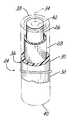
- FIG. 2is a partial perspective view of one embodiment of the flexible member having an inner elastomeric member formed with an outer fabric layer and an outer elastomeric member with a portion of each of the fabric layer and elastomeric jacket removed;
- FIG. 3is a diagrammatic perspective view of one method of forming the outer fabric layer around the inner elastomeric member
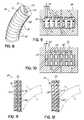
- FIG. 4is a diagrammatic cross-sectional view of one method of forming the outer elastomeric member around the outer fabric layer and the inner elastomeric member of FIG. 2 with a mold;
- FIG. 5is a partial cross-sectional view of one embodiment of the flexible member formed with the mold illustrated in FIG. 4 ;
- FIGS. 6 and 7are partial perspective views of another method of forming the outer elastomeric member around the outer fabric layer and the inner elastomeric member of FIG. 2 ;
- FIG. 8is a partial perspective view of another embodiment of the flexible member having an elongated core member with a plurality of spaced-apart annular protrusions interspersed with a plurality of ring-shaped members;
- FIGS. 9 and 10are diagrammatic cross-sectional views of methods of forming the flexible member of FIG. 8 with a mold
- FIGS. 11 and 12are partial cross-sections of embodiments of the flexible member of FIG. 8 ;
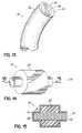
- FIG. 13is a partial perspective view of another embodiment of the flexible member with an elongated polymeric member and outer NiTiNOL jacket;
- FIGS. 14 and 15depict a perspective view and a cross-sectional view, respectively, of another embodiment of the flexible member with a central core that extends beyond an outer core and having a cover covering both the central core and the outer core.
- FIG. 1depicts a portion of a spinal column 10 having a motion segment 12 .
- Each motion segment 12has adjacent vertebrae 14 , 16 with an intervertebral disc 18 positioned therebetween.
- a first anchor member 20is secured in one vertebra 14 and a second anchor member 22 is secured in the adjacent vertebra 16 .
- the anchor members 20 , 22may be top-loading, fixed and polyaxial pedicle screws, such as SILHOUETTE® pedicle screws, available from Zimmer Spine Inc., Edina, Minn.
- the motion segment 12facilitates spinal motion during extension and flexion motion as well as during lateral bending all while under axial loading.
- One or more components of the motion segment 12can deteriorate from injury, disease, or age leading to severe pain. As such, treatment methods to stabilize the motion segment 12 may be necessary to relieve pain and restore a patient's mobility.
- a flexible member 24is secured by and between the anchor members 20 , 22 .
- the flexible member 24is secured to each anchor member 20 , 22 to support that motion segment 12 .
- a variety of means for securing the flexible member 24 to each of the anchor members 20 , 22will be apparent to those skilled in the art.
- the flexible member 24may be held in place by a set screw frictionally engaged with a ferrule placed over the flexible member 24 .
- the flexible member 24is compressed with a split bushing engaged by the set screw or a locking collar.
- the flexible member 24may fit commercially available, top-loading, fixed and polyaxial pedicle screws, such as those designed to receive a variety of different diameter rigid fixation rods.
- the flexible member 24provides stability, strength, and flexibility, without the rigidity of prior art rods, plates, and the like.
- the flexibility of the flexible member 24may differ by design depending on the application and anatomical considerations.
- the flexible member 24may be made, for example, of a flexible, homogenous material or a composite of different materials having differing elastic material properties, as will be discussed later.
- the flexible member 24 disclosed hereindoes not require intraoperative assembly and thus reduces operation time.
- the flexible member 24may be provided in varying lengths, for example, twelve- or more inch lengths, so that a surgeon can cut, or shape, the flexible member 24 to fit appropriately between the anchor members 20 , 22 along a specific section of the spine 10 or to accommodate/treat the recipient's disorder.
- FIG. 2depicts one embodiment of the flexible member 24 of FIG. 1 .
- the flexible member 24includes an inner elastomeric member 26 and an outer fabric layer 28 situated securely around the inner elastomeric member 26 .
- the flexible member 24further includes an outer covering 30 and, in one embodiment, the outer covering 30 is an outer elastomeric member 32 situated securely around the outer fabric layer 28 .
- the inner elastomeric member 26 , the outer fabric layer 28 , and the outer elastomeric member 32have a common lengthwise axis 34 and define a body 36 including opposing first 38 and second ends 40 , with each opposing end 38 , 40 configured for cooperation with one of the anchor members 20 , 22 .
- the inner elastomeric member 26 and the outer elastomeric member 32are characterized as having a first elasticity and a second elasticity, respectively.
- the second elasticityis different than the first elasticity to provide the flexible member 24 with the desired flexibility that may be optimized to treat a particular individual's disorder.
- the second elasticitymay be less than the first elasticity.
- the inner elastomeric member 26may comprise polycarbonate based polyurethane (PCU) having a hardness of, for example, Shore durometer 75D.
- the outer elastomeric member 32may be a similar material with a lower hardness.
- the outer fabric layer 28may comprise, for instance, polyester, polypropylene, polyaramids, acrylics, polyacrylics, polyamides, polyethylene terephthalate, silks, carbon, graphite, highly oriented crystalline polyethylene fibers (for example, SPECTRA® 1000 and DYNEEMA®), combinations thereof or other fibers that may be bonded with the inner elastomeric member 26 .
- the outer fabric layer 28may comprise a single or double knitted layer, braids, or non-wovens such as felts, unidirectional fiber layups, or random layups.
- the outer fabric layer 28provides tensile properties greater than the elastomeric members 26 , 32 to allow for flexion of the flexible member 24 while maintaining the integrity of the flexible member 24 .
- each of the inner elastomeric member 26 and the outer elastomeric member 32may be configured to affect the flexibility of the flexible member 24 .
- the dimensions of each of the inner elastomeric member 26 , the fabric layer 28 , and the outer elastomeric member 32can be adjusted to influence the desired flexibility of the flexible member 24 .
- the shape of the inner elastomeric member 26may also influence the desired flexibility.
- the inner elastomeric member 26may be rod-shaped, as shown in FIG. 2 , having a circular cross section, though the inner elastomeric member 26 may be another anatomically compatible shape such as a square, oval or rectangular cross-section.
- the inner elastomeric member 26may be rod-shaped with an aperture 42 extending therethrough to accept a guide wire which may facilitate percutaneous surgery.
- the ends 38 , 40 of the flexible member 24are configured to cooperate with the anchor members 20 , 22 , at least one end 38 , 40 may optionally have a penetrating obturator tip to facilitate insertion of the flexible member 24 through tissue.
- the overall shape of the flexible member 24 and the elasticity and dimensions of each of the inner elastomeric member 26 , the fabric layer 28 , and the outer elastomeric member 32may be tailored to a recipient's anatomy, size, or diagnosis or even facilitate surgical installation.
- the flexible member 24may serve to support the motion segment 12 by, for example, reducing the load on the intervertebral disc 18 and/or facet joints.
- the separation of the adjacent vertebrae 14 , 16may be restored, for example, posterior distraction, to eliminate crushing or slipping of the disc 18 therebetween.
- lordosis or klyphosismay be created/preserved where desired using the flexible member 24 .
- idiopathic scoliosismay be treated with one or more of the flexible members 24 , as disclosed herein.
- FIGS. 3 and 4depict one method of making the flexible member 24 of FIG. 2 .
- the methodincludes placing and shrinking, for example, heat shrinking, a fabric member 44 about the inner elastomeric member 26 to securely situate the fabric member 44 therearound thereby defining the fabric layer 28 .
- the outer diameter, D 1of the fabric member 44 prior to heat shrinking is larger than the outer diameter, D 2 , of the fabric layer 28 following heat shrinking.
- the fabric layer 28 and inner elastomeric member 26are situated in a mold 46 as shown in FIG. 4 .
- a liquefied elastomeric material 48is introduced therein to surround the fabric layer 28 .
- the liquefied elastomeric material 48is solidified to provide the outer elastomeric member 32 .
- the mold 46may have two parts 46 a , 46 b , as shown, which separate or otherwise open after the liquefied elastomeric material 48 sets.
- the liquefied elastomeric material 48may penetrate the fabric layer 28 and contact the inner elastomeric member 26 to integrate the inner elastomeric member 26 with the fabric layer 28 and the outer elastomeric member 32 .
- FIG. 5illustrates a cross section of one embodiment of the flexible member 24 with the outer elastomeric member 32 penetrating into the fabric layer 28 .
- the fabric layer 28is coated with a solution that penetrates the fabric layer 28 .
- coatingmay comprise repeated dipping of the inner elastomeric member 26 and the fabric layer 28 in the solution to buildup the outer elastomeric member 32 .
- the solutionmay facilitate securing the fabric layer 28 to the inner elastomeric member 26 or the solution may cover the fabric layer 28 , possibly to prevent premature degradation thereof.
- the flexibility of the flexible member 24may vary from the first end 38 to the second end 40 . If necessary, following heat shrinking the fabric member 44 or following providing the outer elastomeric member 32 to the fabric layer 28 , the flexible member 24 may be annealed to relieve forming stresses.
- FIGS. 6 and 7depict another method of making the flexible member 24 of FIG. 2 .
- a plurality of layers of material 50 a , 50 b , 50 c . . . 50 n(where “n” represents the n th layer) which may be, for example, elastomeric material, are rolled around the fabric layer 28 as shown in FIG. 6 .
- Each layer of material 50 a , 50 b , 50 c . . . 50 nis then consolidated into a consolidated rolled layer 50 by additional heat treatment, as shown in FIG. 7 .
- each layer 50 a , 50 b , 50 c , 50 nmay comprise a different elastomeric material, thus in one embodiment the construction of the flexible member 24 may provide a variable cross-section elasticity.
- FIG. 8Another embodiment of the flexible member 24 of FIG. 1 is shown in FIG. 8 and may be generally described as a flexible, heterogeneous composite rod.
- This flexible member 24includes an elongated core member 52 including a plurality of spaced-apart annular protrusions 54 oriented perpendicular to the lengthwise axis 34 with each space between pairs of protrusions defining a circumferential groove 58 .
- the flexible member 24further includes a plurality of ring-shaped members 60 having a circular shape, for example. In alternative embodiments, other shapes for the ring-shaped members may be used such as square, oval, or rectangular cross-sections.
- Each one of the plurality of ring-shaped members 60is securely situated about the elongated core member 52 within a respective circumferential groove 58 .
- the annular protrusions 54alternate with the ring-shaped members 60 along the lengthwise axis 34 thereby defining the body 36 .
- the body 36includes opposing first and second ends 38 , 40 , ( 40 not shown for simplicity) with each end 38 , 40 configured for cooperation with one anchor member 20 , 22 as shown in FIG. 1 . While it may appear in FIG. 11 that the thickness of each of the annular protrusions 54 are similar to the thickness of each of the ring-shaped members 60 , the two thicknesses need not be similar. Furthermore, the thicknesses of the ring-shaped members 60 may vary from first end 38 to second end 40 or from each end 38 , 40 into the center of the body 36 . Similarly, the annular protrusion 54 need not be equal in thickness along the body 36 and may vary from one end to the other or from the ends 38 , 40 into the center of the body 36 .
- the annular protrusions 54 and elongated core member 52further define a monolith having a first elasticity.
- the ring-shaped members 60have a second elasticity different than the first elasticity which may be combined with the thickness variation, as discussed previously, to provide a graduated flexibility along the lengthwise axis 34 of the flexible member 24 .
- the second elasticityis greater than the first elasticity, i.e., the ring-shaped member 60 comprises a material that is more flexible than that of the elongated core member 52 .
- the first elasticityis greater than the second elasticity, i.e., the elongated core member 52 and annular protrusions 54 comprise a material that is more flexible than that of the ring-shaped member 60 .
- the lower elastic materialmay comprise a biocompatible metal such as stainless steel, titanium, or nitinol, or polymers such as polysulfone, polimide, PEEK, Ultra PAEK, or Shore 75D PCU.
- the higher elastic materialmay comprise polyurethane, silicone, or other biocompatible, low modulus material.
- embodiments of the flexible member 24 illustrated in FIG. 8may have a rod-shape, as shown, though the shape of the body 36 is not limited thereto.
- the body 36includes the aperture 42 extending therethrough which may be utilized during a percutaneous procedure, as previously described.
- another method of making the flexible member 24 of FIG. 8includes aligning the ring-shaped members 60 in the mold 46 .
- Each ring-shaped member 60includes a central aperture 61 .
- the ring-shaped members 60may be oriented perpendicular to the lengthwise axis 34 .
- the spaces between the ring-shaped members 60 and apertures 61are filled with the liquefied material 62 .
- the liquefied material 62is then solidified to define the body 36 , as shown in FIG. 11 .
- FIG. 10depicts another method of making the flexible member 24 of FIG. 8 .
- One embodiment of the methodincludes providing the elongated core member 52 with spaced-apart circumferential grooves 58 about the lengthwise axis 34 thereof to define the spaced-apart annular protrusions 54 oriented perpendicular to the lengthwise axis 34 .
- Such elongated core member 52may be formed, for example, via injection molding or by being lathed from a solid elongated core.
- the elongated core member 52is situated in the mold 46 and the grooves 58 are filled with a liquefied material 62 .
- the liquefied material 62is solidified to provide the ring-shaped members 60 as shown in FIG. 12 .
- Each one of the ring-shaped members 60is securely situated about the elongated core member 52 within a respective circumferential groove 58 and adjacent corresponding annular protrusions 54 thereby defining the body 36 .
- the annular protrusions 54 and the elongated core member 52define a monolith having a first elasticity.
- the ring-shaped members 60each have a second elasticity. The second elasticity may be different than the first elasticity. As shown in FIG. 12 , the combination of the first and second elasticities may be tailored to provide the flexible member 24 with a desired flexibility.
- the flexible member 24includes an elongated polymeric member 64 and an outer nitinol member 66 situated securely around the elongated polymeric member 64 .
- the elongated polymeric member 64 and outer nitinol member 66define the body 36 including opposing first and second ends 38 , 40 , ( 40 not shown for simplicity) with each opposing end 38 , 40 configured for cooperation with one anchor member 20 , 22 (shown in FIG. 1 ).
- the elongated polymeric member 64further has a first elasticity and the outer nitinol member 66 has a second elasticity different than the first elasticity to provide the flexible member 24 with a desired flexibility.
- the elongated polymeric member 64may comprise similar materials as the inner elastomeric member 26 described previously with respect to FIGS. 2 and 8 .
- the first elasticityis greater than the second elasticity.
- the second elasticityis greater than the first elasticity.
- the outer nitinol member 66may be one or more other shape memory alloys that are biocompatible. Similar to the previous embodiments, the thickness of the outer nitinol member 66 may be varied.
- the flexible member 24comprises the inner elastomeric member 26 and the outer elastomeric member 32 wherein the inner elastomeric member 26 extends or projects along the lengthwise axis 34 beyond the outer elastomeric member 32 .
- a cover 68encloses the inner elastomeric member 26 and the outer elastomeric member 32 .
- the opposing ends 38 , 40comprise the inner elastomeric member 26 enclosed with the cover 68 .
- the inner elastomeric member 26 with the cover 68is sized to cooperate with the anchor members 20 , 22 (shown in FIG.
- the outer elastomeric member 32may provide only compressive support to the motion segment 12 .
- the anchor members 20 , 22approach one another due to compression of the disc 18 , only the inner elastomeric member 26 of FIG. 15 compresses.
- the outer elastomeric member 32may support the inner elastomeric member 26 during this motion by preventing the inner elastomeric member 26 from bowing.
- the anchor members 20 , 22may contact the outer elastomeric member 32 .
- the outer elastomeric member 32may begin to compress thereby providing additional compressive support to the disc 18 .
- the methodcomprises assessing the patient's spine, for example, by x-ray or MRI imaging, as are known in the art.
- the practitionermay select one of a plurality of implants 70 each having different elastic characteristics for implantation and attachment to one or more bone anchors or anchor members 20 , 22 , as depicted in FIG. 1 .
- the implant 70is at least a portion of the flexible member 24 , described above.
- the practitionermay select a flexible member 24 and trim or cut the flexible member 24 to length for implantation between the bone anchors.
- the implant 70is made per the methods for making the flexible member 24 , described herein, according to the assessment.
- the implant 70comprises an inner portion 72 of one elastomeric material and an outer portion 74 of another or second elastomeric material.
- the inner and outer portions 72 , 74may have different elastomeric properties, for example, the elasticity of the inner portion 72 may be greater than the elasticity of the outer portion 74 .
- the elastic properties of the implant 70may be controlled or customized for a particular patient. While the elastic properties may be individually tailored, one skilled in the art will appreciate that the implant 70 may be manufactured such that a variety of implants with graduated increments of elasticity are readily available.
Landscapes
- Health & Medical Sciences (AREA)
- Orthopedic Medicine & Surgery (AREA)
- Life Sciences & Earth Sciences (AREA)
- Neurology (AREA)
- Surgery (AREA)
- Heart & Thoracic Surgery (AREA)
- Engineering & Computer Science (AREA)
- Biomedical Technology (AREA)
- Nuclear Medicine, Radiotherapy & Molecular Imaging (AREA)
- Medical Informatics (AREA)
- Molecular Biology (AREA)
- Animal Behavior & Ethology (AREA)
- General Health & Medical Sciences (AREA)
- Public Health (AREA)
- Veterinary Medicine (AREA)
- Prostheses (AREA)
Abstract
Description
Claims (9)
Priority Applications (3)
| Application Number | Priority Date | Filing Date | Title |
|---|---|---|---|
| US11/923,340US8043339B2 (en) | 2007-10-24 | 2007-10-24 | Flexible member for use in a spinal column and method for making |
| EP08840986AEP2219540A2 (en) | 2007-10-24 | 2008-10-14 | Flexible member for use in a spinal column and method for making |
| PCT/US2008/079871WO2009055280A2 (en) | 2007-10-24 | 2008-10-14 | Flexible member for use in a spinal column and method for making |
Applications Claiming Priority (1)
| Application Number | Priority Date | Filing Date | Title |
|---|---|---|---|
| US11/923,340US8043339B2 (en) | 2007-10-24 | 2007-10-24 | Flexible member for use in a spinal column and method for making |
Publications (2)
| Publication Number | Publication Date |
|---|---|
| US20090112265A1 US20090112265A1 (en) | 2009-04-30 |
| US8043339B2true US8043339B2 (en) | 2011-10-25 |
Family
ID=40225420
Family Applications (1)
| Application Number | Title | Priority Date | Filing Date |
|---|---|---|---|
| US11/923,340Active2030-08-04US8043339B2 (en) | 2007-10-24 | 2007-10-24 | Flexible member for use in a spinal column and method for making |
Country Status (3)
| Country | Link |
|---|---|
| US (1) | US8043339B2 (en) |
| EP (1) | EP2219540A2 (en) |
| WO (1) | WO2009055280A2 (en) |
Cited By (6)
| Publication number | Priority date | Publication date | Assignee | Title |
|---|---|---|---|---|
| US20090270921A1 (en)* | 2008-02-14 | 2009-10-29 | Krause William R | Flexible spine components having a concentric slot |
| US20120029564A1 (en)* | 2010-07-29 | 2012-02-02 | Warsaw Orthopedic, Inc. | Composite Rod for Spinal Implant Systems With Higher Modulus Core and Lower Modulus Polymeric Sleeve |
| US20140257393A1 (en)* | 2013-03-07 | 2014-09-11 | Warsaw Orthopedic, Inc. | Rotational offset oval vertebral rod |
| US20150142058A1 (en)* | 2012-06-18 | 2015-05-21 | Bruce Francis Hodgson | Method and apparatus for the treatment of scoliosis |
| US10327818B2 (en) | 2012-06-18 | 2019-06-25 | Bruce Francis Hodgson | Method and apparatus for the treatment of scoliosis |
| US11583318B2 (en) | 2018-12-21 | 2023-02-21 | Paradigm Spine, Llc | Modular spine stabilization system and associated instruments |
Families Citing this family (85)
| Publication number | Priority date | Publication date | Assignee | Title |
|---|---|---|---|---|
| US7833250B2 (en) | 2004-11-10 | 2010-11-16 | Jackson Roger P | Polyaxial bone screw with helically wound capture connection |
| US7862587B2 (en) | 2004-02-27 | 2011-01-04 | Jackson Roger P | Dynamic stabilization assemblies, tool set and method |
| US10729469B2 (en) | 2006-01-09 | 2020-08-04 | Roger P. Jackson | Flexible spinal stabilization assembly with spacer having off-axis core member |
| US10258382B2 (en) | 2007-01-18 | 2019-04-16 | Roger P. Jackson | Rod-cord dynamic connection assemblies with slidable bone anchor attachment members along the cord |
| US8292926B2 (en) | 2005-09-30 | 2012-10-23 | Jackson Roger P | Dynamic stabilization connecting member with elastic core and outer sleeve |
| US8353932B2 (en) | 2005-09-30 | 2013-01-15 | Jackson Roger P | Polyaxial bone anchor assembly with one-piece closure, pressure insert and plastic elongate member |
| US8876868B2 (en) | 2002-09-06 | 2014-11-04 | Roger P. Jackson | Helical guide and advancement flange with radially loaded lip |
| US7621918B2 (en) | 2004-11-23 | 2009-11-24 | Jackson Roger P | Spinal fixation tool set and method |
| US7377923B2 (en) | 2003-05-22 | 2008-05-27 | Alphatec Spine, Inc. | Variable angle spinal screw assembly |
| US8926670B2 (en) | 2003-06-18 | 2015-01-06 | Roger P. Jackson | Polyaxial bone screw assembly |
| US7766915B2 (en) | 2004-02-27 | 2010-08-03 | Jackson Roger P | Dynamic fixation assemblies with inner core and outer coil-like member |
| US8366753B2 (en) | 2003-06-18 | 2013-02-05 | Jackson Roger P | Polyaxial bone screw assembly with fixed retaining structure |
| US7967850B2 (en) | 2003-06-18 | 2011-06-28 | Jackson Roger P | Polyaxial bone anchor with helical capture connection, insert and dual locking assembly |
| US8092500B2 (en) | 2007-05-01 | 2012-01-10 | Jackson Roger P | Dynamic stabilization connecting member with floating core, compression spacer and over-mold |
| US7776067B2 (en) | 2005-05-27 | 2010-08-17 | Jackson Roger P | Polyaxial bone screw with shank articulation pressure insert and method |
| US7527638B2 (en) | 2003-12-16 | 2009-05-05 | Depuy Spine, Inc. | Methods and devices for minimally invasive spinal fixation element placement |
| US11419642B2 (en) | 2003-12-16 | 2022-08-23 | Medos International Sarl | Percutaneous access devices and bone anchor assemblies |
| US7179261B2 (en) | 2003-12-16 | 2007-02-20 | Depuy Spine, Inc. | Percutaneous access devices and bone anchor assemblies |
| JP2007525274A (en) | 2004-02-27 | 2007-09-06 | ロジャー・ピー・ジャクソン | Orthopedic implant rod reduction instrument set and method |
| US11241261B2 (en) | 2005-09-30 | 2022-02-08 | Roger P Jackson | Apparatus and method for soft spinal stabilization using a tensionable cord and releasable end structure |
| US7160300B2 (en) | 2004-02-27 | 2007-01-09 | Jackson Roger P | Orthopedic implant rod reduction tool set and method |
| US8152810B2 (en) | 2004-11-23 | 2012-04-10 | Jackson Roger P | Spinal fixation tool set and method |
| US7651502B2 (en) | 2004-09-24 | 2010-01-26 | Jackson Roger P | Spinal fixation tool set and method for rod reduction and fastener insertion |
| US8926672B2 (en) | 2004-11-10 | 2015-01-06 | Roger P. Jackson | Splay control closure for open bone anchor |
| WO2006057837A1 (en) | 2004-11-23 | 2006-06-01 | Jackson Roger P | Spinal fixation tool attachment structure |
| US8444681B2 (en) | 2009-06-15 | 2013-05-21 | Roger P. Jackson | Polyaxial bone anchor with pop-on shank, friction fit retainer and winged insert |
| US9168069B2 (en) | 2009-06-15 | 2015-10-27 | Roger P. Jackson | Polyaxial bone anchor with pop-on shank and winged insert with lower skirt for engaging a friction fit retainer |
| US9216041B2 (en) | 2009-06-15 | 2015-12-22 | Roger P. Jackson | Spinal connecting members with tensioned cords and rigid sleeves for engaging compression inserts |
| US7901437B2 (en) | 2007-01-26 | 2011-03-08 | Jackson Roger P | Dynamic stabilization member with molded connection |
| WO2007038429A1 (en) | 2005-09-27 | 2007-04-05 | Endius, Inc. | Methods and apparatuses for stabilizing the spine through an access device |
| US8105368B2 (en) | 2005-09-30 | 2012-01-31 | Jackson Roger P | Dynamic stabilization connecting member with slitted core and outer sleeve |
| US7815663B2 (en)* | 2006-01-27 | 2010-10-19 | Warsaw Orthopedic, Inc. | Vertebral rods and methods of use |
| CA2670988C (en) | 2006-12-08 | 2014-03-25 | Roger P. Jackson | Tool system for dynamic spinal implants |
| US8475498B2 (en) | 2007-01-18 | 2013-07-02 | Roger P. Jackson | Dynamic stabilization connecting member with cord connection |
| US8366745B2 (en) | 2007-05-01 | 2013-02-05 | Jackson Roger P | Dynamic stabilization assembly having pre-compressed spacers with differential displacements |
| US8012177B2 (en) | 2007-02-12 | 2011-09-06 | Jackson Roger P | Dynamic stabilization assembly with frusto-conical connection |
| EP1972289B1 (en)* | 2007-03-23 | 2018-10-17 | coLigne AG | Elongated stabilization member and bone anchor useful in bone and especially spinal repair processes |
| US10383660B2 (en) | 2007-05-01 | 2019-08-20 | Roger P. Jackson | Soft stabilization assemblies with pretensioned cords |
| US8979904B2 (en) | 2007-05-01 | 2015-03-17 | Roger P Jackson | Connecting member with tensioned cord, low profile rigid sleeve and spacer with torsion control |
| US9017384B2 (en)* | 2008-05-13 | 2015-04-28 | Stryker Spine | Composite spinal rod |
| AU2010260521C1 (en) | 2008-08-01 | 2013-08-01 | Roger P. Jackson | Longitudinal connecting member with sleeved tensioned cords |
| US9408649B2 (en)* | 2008-09-11 | 2016-08-09 | Innovasis, Inc. | Radiolucent screw with radiopaque marker |
| US8118840B2 (en) | 2009-02-27 | 2012-02-21 | Warsaw Orthopedic, Inc. | Vertebral rod and related method of manufacture |
| CN103826560A (en) | 2009-06-15 | 2014-05-28 | 罗杰.P.杰克逊 | Polyaxial Bone Anchor with Socket Stem and Winged Inserts with Friction Fit Compression Collars |
| US8998959B2 (en) | 2009-06-15 | 2015-04-07 | Roger P Jackson | Polyaxial bone anchors with pop-on shank, fully constrained friction fit retainer and lock and release insert |
| US9668771B2 (en) | 2009-06-15 | 2017-06-06 | Roger P Jackson | Soft stabilization assemblies with off-set connector |
| US11229457B2 (en) | 2009-06-15 | 2022-01-25 | Roger P. Jackson | Pivotal bone anchor assembly with insert tool deployment |
| US20110009906A1 (en)* | 2009-07-13 | 2011-01-13 | Zimmer Spine, Inc. | Vertebral stabilization transition connector |
| US9433439B2 (en)* | 2009-09-10 | 2016-09-06 | Innovasis, Inc. | Radiolucent stabilizing rod with radiopaque marker |
| US9011494B2 (en)* | 2009-09-24 | 2015-04-21 | Warsaw Orthopedic, Inc. | Composite vertebral rod system and methods of use |
| EP2485654B1 (en) | 2009-10-05 | 2021-05-05 | Jackson P. Roger | Polyaxial bone anchor with non-pivotable retainer and pop-on shank, some with friction fit |
| US8328849B2 (en)* | 2009-12-01 | 2012-12-11 | Zimmer Gmbh | Cord for vertebral stabilization system |
| US20110152937A1 (en)* | 2009-12-22 | 2011-06-23 | Warsaw Orthopedic, Inc. | Surgical Implants for Selectively Controlling Spinal Motion Segments |
| US8801712B2 (en)* | 2010-03-08 | 2014-08-12 | Innovasis, Inc. | Radiolucent bone plate with radiopaque marker |
| US8740945B2 (en) | 2010-04-07 | 2014-06-03 | Zimmer Spine, Inc. | Dynamic stabilization system using polyaxial screws |
| US8382803B2 (en) | 2010-08-30 | 2013-02-26 | Zimmer Gmbh | Vertebral stabilization transition connector |
| AU2011299558A1 (en)* | 2010-09-08 | 2013-05-02 | Roger P. Jackson | Dynamic stabilization members with elastic and inelastic sections |
| US8911479B2 (en) | 2012-01-10 | 2014-12-16 | Roger P. Jackson | Multi-start closures for open implants |
| US8911478B2 (en) | 2012-11-21 | 2014-12-16 | Roger P. Jackson | Splay control closure for open bone anchor |
| US10058354B2 (en) | 2013-01-28 | 2018-08-28 | Roger P. Jackson | Pivotal bone anchor assembly with frictional shank head seating surfaces |
| US8852239B2 (en) | 2013-02-15 | 2014-10-07 | Roger P Jackson | Sagittal angle screw with integral shank and receiver |
| US9566092B2 (en) | 2013-10-29 | 2017-02-14 | Roger P. Jackson | Cervical bone anchor with collet retainer and outer locking sleeve |
| US9717533B2 (en) | 2013-12-12 | 2017-08-01 | Roger P. Jackson | Bone anchor closure pivot-splay control flange form guide and advancement structure |
| US9451993B2 (en) | 2014-01-09 | 2016-09-27 | Roger P. Jackson | Bi-radial pop-on cervical bone anchor |
| US9597119B2 (en) | 2014-06-04 | 2017-03-21 | Roger P. Jackson | Polyaxial bone anchor with polymer sleeve |
| US10064658B2 (en) | 2014-06-04 | 2018-09-04 | Roger P. Jackson | Polyaxial bone anchor with insert guides |
| US11375975B2 (en) | 2016-01-11 | 2022-07-05 | Kambiz Behzadi | Quantitative assessment of implant installation |
| US11751807B2 (en) | 2016-01-11 | 2023-09-12 | Kambiz Behzadi | Invasive sense measurement in prosthesis installation and bone preparation |
| US11331069B2 (en) | 2016-01-11 | 2022-05-17 | Kambiz Behzadi | Invasive sense measurement in prosthesis installation |
| US11458028B2 (en) | 2016-01-11 | 2022-10-04 | Kambiz Behzadi | Prosthesis installation and assembly |
| US11241248B2 (en) | 2016-01-11 | 2022-02-08 | Kambiz Behzadi | Bone preparation apparatus and method |
| US11298102B2 (en) | 2016-01-11 | 2022-04-12 | Kambiz Behzadi | Quantitative assessment of prosthesis press-fit fixation |
| US11399946B2 (en) | 2016-01-11 | 2022-08-02 | Kambiz Behzadi | Prosthesis installation and assembly |
| US11234840B2 (en) | 2016-01-11 | 2022-02-01 | Kambiz Behzadi | Bone preparation apparatus and method |
| US10251663B2 (en) | 2016-01-11 | 2019-04-09 | Kambiz Behzadi | Bone preparation apparatus and method |
| US11291426B2 (en) | 2016-01-11 | 2022-04-05 | Kambiz Behzadi | Quantitative assessment of implant bone preparation |
| US11109802B2 (en) | 2016-01-11 | 2021-09-07 | Kambiz Behzadi | Invasive sense measurement in prosthesis installation and bone preparation |
| US12193951B2 (en) | 2016-01-11 | 2025-01-14 | Kambiz Behzadi | Quantitative assessment of prosthesis press-fit fixation |
| US11534314B2 (en) | 2016-01-11 | 2022-12-27 | Kambiz Behzadi | Quantitative assessment of prosthesis press-fit fixation |
| US10864083B2 (en) | 2016-04-07 | 2020-12-15 | Kambiz Behzadi | Mechanical assembly including exterior surface preparation |
| US11406504B2 (en) | 2016-06-12 | 2022-08-09 | Kambiz Behzadi | Mechanical assembly including exterior surface preparation |
| WO2019200071A1 (en)* | 2018-04-11 | 2019-10-17 | Wonderhealth Llc | Temporarily flexible implantable rod placement and fabrication |
| US11969336B2 (en) | 2018-10-08 | 2024-04-30 | Kambiz Behzadi | Connective tissue grafting |
| WO2021068009A1 (en)* | 2019-09-30 | 2021-04-08 | Hendrik Davis Johannes | Skeletal support member |
| JP7432538B2 (en)* | 2021-01-05 | 2024-02-16 | グローブライド株式会社 | Rod for spinal fixation device and spinal fixation device equipped with the same |
Citations (17)
| Publication number | Priority date | Publication date | Assignee | Title |
|---|---|---|---|---|
| US4743260A (en) | 1985-06-10 | 1988-05-10 | Burton Charles V | Method for a flexible stabilization system for a vertebral column |
| US5540688A (en)* | 1991-05-30 | 1996-07-30 | Societe "Psi" | Intervertebral stabilization device incorporating dampers |
| US20030061839A1 (en)* | 2001-10-03 | 2003-04-03 | Kost David William | Knitted fabric |
| WO2003047441A1 (en) | 2001-12-07 | 2003-06-12 | Mathys Medizinaltechnik Ag | Damping element |
| WO2004096066A2 (en) | 2003-04-25 | 2004-11-11 | Kitchen Michael S | Spinal curvature correction device |
| US20050203517A1 (en)* | 2003-09-24 | 2005-09-15 | N Spine, Inc. | Spinal stabilization device |
| US20050277922A1 (en)* | 2004-06-09 | 2005-12-15 | Trieu Hai H | Systems and methods for flexible spinal stabilization |
| US20060009768A1 (en) | 2002-04-05 | 2006-01-12 | Stephen Ritland | Dynamic fixation device and method of use |
| US6986771B2 (en) | 2003-05-23 | 2006-01-17 | Globus Medical, Inc. | Spine stabilization system |
| US20060155279A1 (en)* | 2004-10-28 | 2006-07-13 | Axial Biotech, Inc. | Apparatus and method for concave scoliosis expansion |
| US20070129729A1 (en)* | 2004-03-02 | 2007-06-07 | Spinevision, A Corporation Of France | Dynamic linking element for a spinal attachment system, and spinal attachment system including said linking element |
| WO2007087476A1 (en) | 2006-01-27 | 2007-08-02 | Warsaw Orthopedic, Inc. | Spinal rods having different flexural rigidities about different axes and methods of use |
| WO2007097905A2 (en) | 2006-02-17 | 2007-08-30 | Holt Development L.L.C. | Apparatus and method for flexible spinal fixation |
| WO2007127604A2 (en) | 2006-04-25 | 2007-11-08 | Warsaw Orthopedic, Inc. | Surgical instruments and techniques for controlling spinal motion segments with positioning of spinal stabilization elements |
| US20080234744A1 (en)* | 2007-03-21 | 2008-09-25 | Emmanuel Zylber | Spinal stabilization system with rigid and flexible elements |
| US20080269804A1 (en)* | 2006-02-17 | 2008-10-30 | Holt Development L.L.C. | Apparatus and method for flexible spinal fixation |
| US7763052B2 (en)* | 2003-12-05 | 2010-07-27 | N Spine, Inc. | Method and apparatus for flexible fixation of a spine |
Family Cites Families (1)
| Publication number | Priority date | Publication date | Assignee | Title |
|---|---|---|---|---|
| EP1646332B1 (en)* | 2003-07-18 | 2015-06-17 | Edwards Lifesciences AG | Remotely activated mitral annuloplasty system |
- 2007
- 2007-10-24USUS11/923,340patent/US8043339B2/enactiveActive
- 2008
- 2008-10-14EPEP08840986Apatent/EP2219540A2/ennot_activeWithdrawn
- 2008-10-14WOPCT/US2008/079871patent/WO2009055280A2/enactiveApplication Filing
Patent Citations (18)
| Publication number | Priority date | Publication date | Assignee | Title |
|---|---|---|---|---|
| US4743260A (en) | 1985-06-10 | 1988-05-10 | Burton Charles V | Method for a flexible stabilization system for a vertebral column |
| US5540688A (en)* | 1991-05-30 | 1996-07-30 | Societe "Psi" | Intervertebral stabilization device incorporating dampers |
| US20030061839A1 (en)* | 2001-10-03 | 2003-04-03 | Kost David William | Knitted fabric |
| WO2003047441A1 (en) | 2001-12-07 | 2003-06-12 | Mathys Medizinaltechnik Ag | Damping element |
| US20060009768A1 (en) | 2002-04-05 | 2006-01-12 | Stephen Ritland | Dynamic fixation device and method of use |
| WO2004096066A2 (en) | 2003-04-25 | 2004-11-11 | Kitchen Michael S | Spinal curvature correction device |
| US6986771B2 (en) | 2003-05-23 | 2006-01-17 | Globus Medical, Inc. | Spine stabilization system |
| US20050203517A1 (en)* | 2003-09-24 | 2005-09-15 | N Spine, Inc. | Spinal stabilization device |
| US7326210B2 (en)* | 2003-09-24 | 2008-02-05 | N Spine, Inc | Spinal stabilization device |
| US7763052B2 (en)* | 2003-12-05 | 2010-07-27 | N Spine, Inc. | Method and apparatus for flexible fixation of a spine |
| US20070129729A1 (en)* | 2004-03-02 | 2007-06-07 | Spinevision, A Corporation Of France | Dynamic linking element for a spinal attachment system, and spinal attachment system including said linking element |
| US20050277922A1 (en)* | 2004-06-09 | 2005-12-15 | Trieu Hai H | Systems and methods for flexible spinal stabilization |
| US20060155279A1 (en)* | 2004-10-28 | 2006-07-13 | Axial Biotech, Inc. | Apparatus and method for concave scoliosis expansion |
| WO2007087476A1 (en) | 2006-01-27 | 2007-08-02 | Warsaw Orthopedic, Inc. | Spinal rods having different flexural rigidities about different axes and methods of use |
| WO2007097905A2 (en) | 2006-02-17 | 2007-08-30 | Holt Development L.L.C. | Apparatus and method for flexible spinal fixation |
| US20080269804A1 (en)* | 2006-02-17 | 2008-10-30 | Holt Development L.L.C. | Apparatus and method for flexible spinal fixation |
| WO2007127604A2 (en) | 2006-04-25 | 2007-11-08 | Warsaw Orthopedic, Inc. | Surgical instruments and techniques for controlling spinal motion segments with positioning of spinal stabilization elements |
| US20080234744A1 (en)* | 2007-03-21 | 2008-09-25 | Emmanuel Zylber | Spinal stabilization system with rigid and flexible elements |
Non-Patent Citations (2)
| Title |
|---|
| Cloth, Merriam Webster dictionary, accessed Apr. 4, 2011 http://www.merriam-webster.com/dictionary/cloth.* |
| Fabric, Merriam-Webster Dictionary, accessed Apr. 4, 2011 http://www.merriam-webster.com/dictionary/fabric.* |
Cited By (9)
| Publication number | Priority date | Publication date | Assignee | Title |
|---|---|---|---|---|
| US20090270921A1 (en)* | 2008-02-14 | 2009-10-29 | Krause William R | Flexible spine components having a concentric slot |
| US8353935B2 (en)* | 2008-02-14 | 2013-01-15 | Krause William R | Flexible spine components having a concentric slot |
| US20120029564A1 (en)* | 2010-07-29 | 2012-02-02 | Warsaw Orthopedic, Inc. | Composite Rod for Spinal Implant Systems With Higher Modulus Core and Lower Modulus Polymeric Sleeve |
| US20150142058A1 (en)* | 2012-06-18 | 2015-05-21 | Bruce Francis Hodgson | Method and apparatus for the treatment of scoliosis |
| US10327818B2 (en) | 2012-06-18 | 2019-06-25 | Bruce Francis Hodgson | Method and apparatus for the treatment of scoliosis |
| US20140257393A1 (en)* | 2013-03-07 | 2014-09-11 | Warsaw Orthopedic, Inc. | Rotational offset oval vertebral rod |
| US9101400B2 (en)* | 2013-03-07 | 2015-08-11 | Warsaw Orthopedic, Inc. | Rotational offset oval vertebral rod |
| US11583318B2 (en) | 2018-12-21 | 2023-02-21 | Paradigm Spine, Llc | Modular spine stabilization system and associated instruments |
| US12114895B2 (en) | 2018-12-21 | 2024-10-15 | Xtant Medical Holdings, Inc. | Modular spine stabilization system and associated instruments |
Also Published As
| Publication number | Publication date |
|---|---|
| WO2009055280A2 (en) | 2009-04-30 |
| WO2009055280A3 (en) | 2009-07-23 |
| US20090112265A1 (en) | 2009-04-30 |
| EP2219540A2 (en) | 2010-08-25 |
Similar Documents
| Publication | Publication Date | Title |
|---|---|---|
| US8043339B2 (en) | Flexible member for use in a spinal column and method for making | |
| US20250143752A1 (en) | Spinal Fixation Construct And Methods Of Use | |
| EP2114272B1 (en) | Spine stiffening device and associated method | |
| KR101151497B1 (en) | Dynamic linking element for a spinal attachment system, and spinal attachment system including said linking element | |
| EP2211737B1 (en) | Spinal stabilization system with transition member | |
| US20090259257A1 (en) | Pedicule-Based Motion- Preserving Device | |
| AU2009281847B2 (en) | Vertebral rod system and methods of use | |
| US20090018583A1 (en) | Dynamic spinal stabilization system incorporating a wire rope | |
| US20100160968A1 (en) | Systems and methods for pedicle screw-based spine stabilization using flexible bands | |
| US20090275983A1 (en) | Dynamic stabilization rod | |
| US20090093819A1 (en) | Anisotropic spinal stabilization rod | |
| WO2007097905A2 (en) | Apparatus and method for flexible spinal fixation | |
| CA2680657A1 (en) | System and method for insertion of flexible spinal stabilization element | |
| EP3015084B1 (en) | Spinal fixation member |
Legal Events
| Date | Code | Title | Description |
|---|---|---|---|
| AS | Assignment | Owner name:ZIMMER SPINE, INC., MINNESOTA Free format text:ASSIGNMENT OF ASSIGNORS INTEREST;ASSIGNORS:HUDGINS, ROBERT G.;VIKER, THOMAS O.;HESTAD, HUGH D.;AND OTHERS;REEL/FRAME:020337/0892;SIGNING DATES FROM 20071003 TO 20071031 Owner name:ZIMMER SPINE, INC., MINNESOTA Free format text:ASSIGNMENT OF ASSIGNORS INTEREST;ASSIGNORS:HUDGINS, ROBERT G.;VIKER, THOMAS O.;HESTAD, HUGH D.;AND OTHERS;SIGNING DATES FROM 20071003 TO 20071031;REEL/FRAME:020337/0892 | |
| STCF | Information on status: patent grant | Free format text:PATENTED CASE | |
| FPAY | Fee payment | Year of fee payment:4 | |
| MAFP | Maintenance fee payment | Free format text:PAYMENT OF MAINTENANCE FEE, 8TH YEAR, LARGE ENTITY (ORIGINAL EVENT CODE: M1552); ENTITY STATUS OF PATENT OWNER: LARGE ENTITY Year of fee payment:8 | |
| AS | Assignment | Owner name:ZIMMER BIOMET SPINE, INC., INDIANA Free format text:MERGER;ASSIGNOR:ZIMMER SPINE, INC.;REEL/FRAME:059232/0356 Effective date:20160930 | |
| AS | Assignment | Owner name:JPMORGAN CHASE BANK, N.A., AS ADMINISTRATIVE AGENT, NEW YORK Free format text:SECURITY INTEREST;ASSIGNORS:BIOMET 3I, LLC;EBI, LLC;ZIMMER BIOMET SPINE, INC.;AND OTHERS;REEL/FRAME:059293/0213 Effective date:20220228 | |
| MAFP | Maintenance fee payment | Free format text:PAYMENT OF MAINTENANCE FEE, 12TH YEAR, LARGE ENTITY (ORIGINAL EVENT CODE: M1553); ENTITY STATUS OF PATENT OWNER: LARGE ENTITY Year of fee payment:12 | |
| AS | Assignment | Owner name:CERBERUS BUSINESS FINANCE AGENCY, LLC, NEW YORK Free format text:GRANT OF A SECURITY INTEREST -- PATENTS;ASSIGNORS:ZIMMER BIOMET SPINE, LLC;EBI, LLC;REEL/FRAME:066970/0806 Effective date:20240401 | |
| AS | Assignment | Owner name:ZIMMER BIOMET SPINE, LLC (F/K/A ZIMMER BIOMET SPINE, INC.), COLORADO Free format text:RELEASE BY SECURED PARTY;ASSIGNOR:JPMORGAN CHASE BANK, N.A.;REEL/FRAME:066973/0833 Effective date:20240401 Owner name:EBI, LLC, NEW JERSEY Free format text:RELEASE BY SECURED PARTY;ASSIGNOR:JPMORGAN CHASE BANK, N.A.;REEL/FRAME:066973/0833 Effective date:20240401 | |
| AS | Assignment | Owner name:ZIMMER BIOMET SPINE, LLC, COLORADO Free format text:CHANGE OF NAME;ASSIGNOR:ZIMMER BIOMET SPINE, INC.;REEL/FRAME:069772/0121 Effective date:20240220 Owner name:HIGHRIDGE MEDICAL, LLC, COLORADO Free format text:CHANGE OF NAME;ASSIGNOR:ZIMMER BIOMET SPINE, LLC;REEL/FRAME:069772/0248 Effective date:20240405 |