US8043316B2 - Adjustable spacer - Google Patents
Adjustable spacerDownload PDFInfo
- Publication number
- US8043316B2 US8043316B2US12/114,294US11429408AUS8043316B2US 8043316 B2US8043316 B2US 8043316B2US 11429408 AUS11429408 AUS 11429408AUS 8043316 B2US8043316 B2US 8043316B2
- Authority
- US
- United States
- Prior art keywords
- introducer
- cannula
- medical device
- hub
- outer member
- Prior art date
- Legal status (The legal status is an assumption and is not a legal conclusion. Google has not performed a legal analysis and makes no representation as to the accuracy of the status listed.)
- Active, expires
Links
Images


Classifications
- A—HUMAN NECESSITIES
- A61—MEDICAL OR VETERINARY SCIENCE; HYGIENE
- A61B—DIAGNOSIS; SURGERY; IDENTIFICATION
- A61B10/00—Instruments for taking body samples for diagnostic purposes; Other methods or instruments for diagnosis, e.g. for vaccination diagnosis, sex determination or ovulation-period determination; Throat striking implements
- A61B10/02—Instruments for taking cell samples or for biopsy
- A61B10/0233—Pointed or sharp biopsy instruments
Definitions
- the present disclosurerelates to the field of medical devices and more particularly to a medical system that permits introduction of, among other things, minimally invasive surgical instruments and other medical treatments into a patient's body.
- tissue biopsy devicesIn the field of tissue biopsy, minimally invasive biopsy devices have been developed that require only a single insertion point into a patient's body to remove one or more tissue samples.
- One such biopsy deviceincorporates a “tube-within-a-tube” design that includes an outer piercing needle having a sharpened distal end and a lateral opening that defines a tissue receiving port.
- An inner cutting memberis slidingly received within the outer piercing needle, which serves to excise tissue that has prolapsed into the tissue receiving port.
- a vacuumis used to draw the excised tissue into the tissue receiving port and aspirates the excised tissue from the biopsy site once severed.
- Exemplary “tube-within-a-tube” biopsy devicesare disclosed in U.S. Pat. Nos. 6,638,235 and 6,744,824, which are owned by the assignee of the present invention.
- the exemplary biopsy devicescan be used in conjunction with Magnetic Resonance Imaging (MRI). This compatibility is due to the fact that many of the components of the biopsy devices are made of materials that do not interfere with operation of MRI apparatus or are otherwise compatible therewith. It is desirable to perform biopsies in conjunction with MRI because it is a non-invasive visualization modality capable of defining the margins of a tumor.
- MRIMagnetic Resonance Imaging
- Some biopsy devicesmay incorporate an introducer having an introducer cannula that may be placed over the biopsy needle extending from about the biopsy location to a location outside the patient. This introducer may remain in place after a biopsy is taken to permit the biopsy needle to be removed and a marker deployment device to be inserted within the introducer cannula in order to permit a marker to be positioned within the biopsy site.
- an introducerhaving an introducer cannula that may be placed over the biopsy needle extending from about the biopsy location to a location outside the patient. This introducer may remain in place after a biopsy is taken to permit the biopsy needle to be removed and a marker deployment device to be inserted within the introducer cannula in order to permit a marker to be positioned within the biopsy site.
- undesirable amounts of leakage between the outer cannula and the biopsy needle and/or marker deployment devicemay exist.
- biopsy needles and introducersare available in differing lengths, which demands that marker deployment devices be capable of sliding within the introducer a predetermined length for proper marker deployment. While a removable annular spacer positioned between the introducer hub and the marker deployment device may permit the marker deployment device to be inserted to a predetermined depth, interposing the marker deployment device within an annular spacer may increase the risk of contamination. Additionally, a spacer interposed between the introducer hub and the marker deployment device may not secure the introducer hub to the marker deployment device, thereby requiring a user to simultaneously deploy a marker while ensuring that the marker deployment device is properly positioned axially with respect to the desired marker deployment location.
- a favorable introducermay also reduce leakage through the introducer cannula and provide for adjustability for the insertion depth of the marker deployment device.
- a medical targeting and device introduction systemincludes an introducer having a cannula, a hemostatic valve and a hub.
- the cannulais defined, at least in part, by an inner lumen.
- the hubincludes a latch to releasably secure the hub to a biopsy device.
- the hubincludes a proximal end and a distal end. The latch extends from the proximal end, and the hemostatic valve is interposed within the introducer.
- FIG. 1is a partially sectioned side view of a medical system according to an embodiment, with section graphics omitted for clarity.
- FIG. 2is a partially sectioned side view of a portion of the medical system of FIG. 1 , with section graphics omitted for clarity.
- FIG. 3is a side view of a portion of a medical system according to another embodiment.
- FIG. 4is a partially sectioned side view of the medical system of FIG. 3 .
- FIG. 5is a partially sectioned side view of the medical system of FIG. 4 .
- FIG. 6is a partially sectioned side view of a medical system according to a further embodiment.
- FIG. 7is a perspective view of a portion of the medical system of FIG. 6 .
- FIG. 8is a side view of a portion of the medical system of FIG. 6 .
- FIG. 9is a partially sectioned side view of a medical system of FIG. 6 , illustrating additional components.
- FIG. 10is a partially sectioned side view of a medical system according to a further embodiment.
- FIG. 11is a sectioned side view of the medical system of FIG. 10 .
- FIG. 12is an exploded side view of the medical system of FIG. 10 .
- FIG. 13is a sectioned exploded side view of the medical system of FIG. 10 .
- FIG. 14is a view of the medical system of FIG. 10 taken along line 26 - 26 of FIG. 10 , enlarged for clarity.
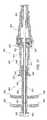
- FIG. 1illustrates a medical system 20 .
- the medical system 20includes a medical device, or biopsy device 22 (illustrated partially) and an introducer 24 generally defining an axis A-A.
- the biopsy device 22includes a cutting element 30 sized for introduction into a patient's body and extends from a hand piece 32 .
- the cutting element 30includes an outer cannula 36 defined by a first outer lumen 38 and a first inner lumen 40 , and an inner cannula 44 sized to fit concentrically within the first inner lumen 40 .
- a motor or other motion generating devicemay be provided with the hand piece 32 to rotate and/or translate inner cannula 44 within outer cannula 36 .
- Biopsy apparatus similar to device 22can be seen by way of example in U.S. Pat. Nos. 6,638,235 and 6,744,824, which are owned by the assignee of the present invention and are incorporated herein by reference in their entirety.
- the outer cannula 36 of the biopsy device 22includes a tissue piercing tip 46 , such as a trocar tip, to facilitate penetration of the system 20 into a patient's tissue.
- a tissue piercing tip 46such as a trocar tip
- the outer cannula 36may include other devices for piercing the patient's tissue, including without limitation, devices that use a laser or radio frequencies (RF) to pierce the tissue.
- RFradio frequencies
- the introducer 24includes an introducer hub 50 , an introducer cannula 52 , and a latch portion 56 .
- system 20is particularly, but not necessarily, suited for use in biopsy procedures that identify the target biopsy site using Magnetic Resonance Imaging (MRI) or comparable medical imaging modality.
- the introducer 24may be made of a MRI compatible, medical grade material, such as 316 stainless steel or InconelTM 625.
- the introducer cannula 52includes a generally cylindrical body 58 having a distal end 60 , a proximal end 62 , an introducer outer lumen 64 , and an introducer inner lumen 66 .
- the distal end 60defines a distal introducer opening 70 .
- the hub 50includes a generally annular hub portion 76 , a hemostatic valve 80 , and the latch portion 56 .
- the annular hub portion 76includes a hub outer surface 82 , a hub inner surface 84 , a hub distal end 86 , and a hub proximal end 88 .
- the hub inner surface 84includes a generally cylindrical introducer cannula mating surface 90 and a generally cylindrical valve mating surface 92 .
- the latch portion 56includes a release button 100 and a latch 102 extending generally parallel to the axis A-A having a latch tab 104 extending generally perpendicular to and toward the axis A-A.
- the biopsy device 22includes a device distal end 106 defined by a distal surface 108 , and a latch portion, or latch opening, 110 .
- the latch opening 110includes a latch tab interference portion 112 .
- the hemostatic valve 80includes a body 120 that is a self-sealing membrane that will permit a medical device, such as the biopsy device 24 or a site marker deployment device, to pass therethrough while sealing around the medical device and will reseal with itself after the medical device is removed from the valve 80 .
- a medical devicesuch as the biopsy device 24 or a site marker deployment device
- a medical devicesuch as the biopsy device 22 partially interposed within the introducer 24 , may include a vacuum source (not shown).
- the vacuum sourcemay aspirate the biopsy site where the biopsy device 22 removes a tissue sample.
- the length of the outer cannula 36 , from the distal surface 108 to the piercing tip 46is identified by the reference character “M” in FIG. 1 .
- the length of the introducer 24 from the distal end 60 to the hub proximal end 88is identified by the reference character “I” in FIG. 1 .
- FIGS. 3-5illustrate an alternative embodiment of the medical system 20 as a medical system 220 .
- the medical system 220includes a medical device, or biopsy device 222 (illustrated partially in FIGS. 3 and 5 ) and an introducer 224 generally defining an axis B-B.
- the biopsy device 222includes a cutting element 230 that extends from a hand piece 232 .
- the cutting element 230includes an outer cannula 236 defined by a first outer lumen 238 and a first inner lumen 240 , and an inner cannula 244 sized to fit concentrically within the first inner lumen 240 .
- a motor or other motion generating devicemay be provided with the hand piece 232 to rotate and/or translate inner cannula 244 within outer cannula 236 .
- the outer cannula 236 of the biopsy device 222includes a tissue piercing tip 246 , such as a trocar tip, to facilitate penetration of the system 220 into a patient's tissue.
- a tissue piercing tip 246such as a trocar tip
- the outer cannula 236may include other devices for piercing the patient's tissue, including without limitation, devices that use a laser or radio frequencies (RF) to pierce the tissue.
- RFradio frequencies
- the introducer 224includes a hub 250 , an introducer cannula 252 , and a latch portion 256 .
- system 220is particularly, but not necessarily, suited for use in biopsy procedures that identify the target biopsy site using Magnetic Resonance Imaging (MRI) or comparable medical imaging modality.
- MRIMagnetic Resonance Imaging
- the introducer cannula 252includes a generally cylindrical body 258 having a distal end 260 , a proximal end 262 , an introducer outer lumen 264 , and an introducer inner lumen 266 .
- the distal end 260defines a distal introducer opening 270 .
- the hub 250includes a generally annular hub portion 276 , a hemostatic valve 280 , and the latch portion 256 .
- the annular hub portion 276includes a hub outer surface 282 , a hub inner surface 284 , a hub distal end 286 , and a hub proximal end 288 .
- the hub inner surface 284includes a generally cylindrical introducer cannula mating surface 290 and a generally cylindrical valve mating surface 292 .
- the latch portion 256includes a release button 300 and a latch 302 extending generally parallel to the axis B-B having a latch tab 304 extending generally perpendicular to the axis B-B.
- the biopsy device 222includes a device distal end 306 defined by a distal surface 308 , a latch opening 310 , and an outer cannula sheath 312 .
- the latch opening 310includes a latch tab interference portion 316 .
- the hemostatic valve 280includes a body 320 having a slit 322 formed therein.
- the slit 322generally segregates the body 320 into a first flap 326 and a second flap 328 interconnected at an outer periphery, or outer edge, 330 such that the slit 322 does not intersect the outer edge 330 .
- the first flap 326is defined by a first flap opening surface 334
- the second flap 328is defined by a second flap opening surface 336 .
- the first flap opening surface 334 and the second flap opening surface 336are formed so as to flex inwardly until the first flap opening surface 334 and the second flap opening surface 336 bindingly contact ( FIG.
- valve 280may be made of a silicone or other suitable material that will bias the first flap 326 and the second flap 328 toward a closed position.
- the first flap opening surface 334 and the second flap opening surface 336are in contact in the closed position of FIG. 4 and provide a seal for the introducer inner lumen 266 when the valve 280 does not have a medical device interposed therein.
- the first flap opening surface 334 and the second flap opening surface 336contact the first outer lumen 238 so as to form a seal therebetween and restrict fluids from leaking therepast and through the introducer cannula 252 .
- the hemostatic valve 280is not punctured with each use, but is a valve having a defined opening.
- FIGS. 6-9illustrate an alternative embodiment of the medical system 20 as a medical system 420 .
- the medical system 420includes a medical device, or site marker deployment device 422 (illustrated partially in FIG. 9 ) and an introducer 424 generally defining an axis C-C.
- the site marker deployment device 422includes a deployment handpiece 430 , a deployment rod 432 , and a deployment cannula 434 extending therefrom.
- the deployment cannula 434includes a generally cylindrical body 436 having a distal deployment end 438 defined, at least in part, by a distal deployment opening 440 , a proximal deployment end 442 , a deployment inner lumen, or inner surface, 444 , and a deployment outer lumen, or outer surface, 446 .
- the deployment inner lumen 444 and the deployment outer lumen 446are generally cylindrical.
- the deployment cannula 434is illustrated in FIG. 9 with a site marker 448 (illustrated in phantom) interposed therein.
- the site marker 448may be an MRI identifiable marker, such as a collagen plug, metal spring, or other medical treatment.
- the deployment rod 432extends at least partially through the hand piece 430 and the deployment cannula 434 and is used to urge the site marker 448 through the distal deployment opening 440 when the deployment device 422 is desirably positioned, as discussed in greater detail below.
- the introducer 424includes a hub 450 , an introducer cannula 452 , and a pair of latch portions 456 .
- system 420is particularly, but not necessarily, suited for use in biopsy procedures that identify the target biopsy site using Magnetic Resonance Imaging (MRI) or comparable medical imaging modality.
- MRIMagnetic Resonance Imaging
- the introducer cannula 452includes a generally cylindrical body 458 having a distal end 460 , a proximal end 462 , an introducer outer lumen 464 , and an introducer inner lumen 466 .
- the distal end 460defines a distal introducer opening 470 .
- the hub 450includes a generally annular hub portion 476 , a first portion, or collar, 478 , a hemostatic valve 480 , and the latch portions 456 .
- the annular hub portion 476includes a hub outer surface 482 , a hub inner surface 484 , a hub distal end 486 , and a hub proximal end 488 .
- the hub inner surface 484includes a generally cylindrical introducer cannula mating surface 490 ( FIG. 9 ) and a generally cylindrical valve mating surface 492 ( FIG. 9 ).
- the collar 478includes a generally cylindrical outer surface 494 and a generally annular collar end surface 496 .
- the hub proximal end 488includes a generally cylindrical hub flange 498 .
- Each latch portion 456includes a release button 500 and a latch 502 extending generally parallel to the axis C-C having a latch tab 504 extending generally perpendicular to the axis C-C.
- the deployment handpiece 430 of the site marker deployment device 422includes a deployment distal end 506 defined by a deployment distal surface 508 .
- the deployment distal end 506has a pair of latch openings 510 and a collar opening 512 formed therein.
- Each latch opening 510includes a latch tab interference portion 514 .
- the collar 478is received within the collar opening 512 .
- the hemostatic valve 480may be a valve 80 or a valve 280 , as desired.
- FIG. 6illustrates the introducer 424 with a medical device, or a biopsy device 528 interposed therein.
- the biopsy device 528includes a cutting element 530 sized for introduction into the patient's body.
- the cutting element 530extends from a handpiece 532 .
- the cutting element 530includes an outer cannula 536 defined by a first outer lumen 538 and a first inner lumen 540 , and an inner cannula 544 sized to fit concentrically within the first inner lumen 540 .
- a motor or other motion generating devicemay be provided with the hand piece 532 to rotate and/or translate inner cannula 544 within outer cannula 536 .
- the outer cannula 536 of the biopsy device 528includes a tissue piercing tip 546 , such as a trocar tip, to facilitate penetration of the system 520 into a patient's tissue.
- a tissue piercing tip 546such as a trocar tip
- the outer cannula 536may include other devices for piercing the patient's tissue, including without limitation, devices that use a laser or radio frequencies (RF) to pierce the tissue.
- RFradio frequencies
- the handpiece 532includes a biopsy device distal end 550 having a biopsy device distal surface 552 for abutting the collar 478 to restrict the movement of the introducer 424 relative to the biopsy device 528 .
- the biopsy device 528 and the introducer 424are coupled such as shown in FIG. 6
- the length of the biopsy device 528 , from the collar end surface 496 to the piercing tip 546is identified by the reference character “A 2 ” in FIG. 6 .
- the length of the introducer 424 from the distal end 460 to the collar end surface 496is identified by the reference character “B 2 ” in FIGS. 6 and 9 .
- the length of the deployment device 422 , from the collar end surface 496 to the distal deployment opening 440is identified by the reference character “C 2 ” in FIG. 9 .
- the length of the introducer 424 from the distal end 460 to the hub proximal end 488is identified by the reference character “D” in FIG. 9 .
- the length of the deployment device 422 , from the hub proximal end 488 to the distal deployment opening 440is identified by the reference character “E” in FIG. 9 .
- a biopsy devicesuch as the biopsy device 528 is coupled with the introducer 424 such that the outer cannula 536 is interposed within the introducer cannula 452 with the piercing tip 546 extending from the distal introducer opening 470 , as generally shown in FIG. 6 .
- the biopsy device 528is inserted into the introducer 424 until the collar end surface 496 contacts the biopsy device distal surface 552 .
- the system 420may be inserted into a patient's tissue to remove a tissue sample from a biopsy site.
- the valve 480seals the introducer cannula such that fluids are restricted from flowing from the distal end 460 to the proximal end 462 .
- the system 420is inserted into a patient's tissue to a desired depth. This desired depth may be determined by viewing the system with a MRI during insertion.
- a tissue sampleis drawn into the outer cannula 536 and separated from the surrounding tissue to form a biopsy site. A vacuum drawn through the outer cannula 536 may be applied to facilitate a complete separation and collection of the tissue sample.
- the biopsy device 528is removed from the tissue as the introducer 424 is maintained in a relatively stable position relative to and within the tissue.
- the valve 480seals with itself to restrict a loss of fluids from the biopsy site.
- the valve 480is a valve 280 where the first flap opening surface 334 and the second flap opening surface 336 flex inwardly until the first flap opening surface 334 and the second flap opening surface 336 bindingly contact ( FIG. 4 ) and provide a seal for the introducer inner lumen 466 .
- the deployment device 422may be inserted into the introducer 424 ( FIG. 9 ).
- the deployment device 422is inserted into the introducer 424 until the deployment distal surface 508 contacts the hub proximal end 488 .
- the deployment cannula 434is sized to fit within the introducer cannula 452 , but need not be snugly fit, since the valve 280 will reduce leakage therebetween.
- the site marker 448may then be deployed by urging the site marker out of the introducer 424 through the distal introducer opening 470 .
- Deployment devices for deploying a site markermay be found in U.S. Pat. No. 7,044,957.
- the deployment device 422 and the introducer 424may be removed simultaneously by urging the deployment handpiece 430 away from the tissue generally in a direction parallel to the axis C-C since the deployment device 422 is latched to the introducer 424 .
- the deployment device 422may be unlatched from the introducer 424 by urging the release buttons 500 inwardly toward the axis C-C to disengage the latch tabs 504 from the latch openings 510 and urge the deployment device 422 away from the introducer 424 .
- valve 280(which may be commonly referred to as a duck bill valve) will permit medical devices to be inserted therethrough while restricting the flow of fluids therethrough.
- the latches described hereinpermit a medical device to be positioned relative to an introducer hub in a desirable, confirmable position for performing a treatment, such as removing tissue or deploying a site marker or other treatment.
- An introducer hubsuch as the introducer hub 50 , 250 , 450 may be positioned relative to the tissue by an indicator on the introducer outer lumen 464 , or a support grid affixed to a MRI device. Additionally, the operation of the systems 20 , 220 are similar to the system 420 , with variations in whether the biopsy device or the deployment device (or both) are latched and unlatched from the introducer hub, as desired.
- FIGS. 10-14illustrate embodiments of the system 20 with adjusting mechanisms for accommodating cannula of differing lengths. That is, briefly, biopsy devices and marker deployment devices may be supplied with lengths of, for example, 10 centimeters (cm), 12 cm, or 14 cm. While introducers with lengths of 10, 12, and 14 cm may be supplied, a user may require a 12 cm introducer cannula for a biopsy device (such as the dimension B 2 of the biopsy device 22 of FIG. 6 ) and a 14 cm introducer cannula for a site marker deployment device (such as the dimension B 2 of the site marker deployment device of FIG. 9 ).
- a 12 cm introducer cannula for a biopsy devicesuch as the dimension B 2 of the biopsy device 22 of FIG. 6
- a 14 cm introducer cannulafor a site marker deployment device (such as the dimension B 2 of the site marker deployment device of FIG. 9 ).
- the usermay attempt to insert the deployment device partially, estimate when the deployment device is 2 cm from full insertion into an introducer (where full insertion is shown FIG. 9 ), and deploy the marker. This method may not provide the desired precision of marker positioning. Further, a user may stock multiple deployment devices having cannula of differing lengths to precisely deploy a marker depending upon the cannula length of the biopsy device employed.
- FIGS. 10-14illustrate another embodiment of a spacer for a medical device as a spacer 900 .
- the spacer 900includes an outer hub 902 and an inner hub 904 .
- FIGS. 10 and 11illustrate the spacer 900 coupled to an introducer 906 and having a push rod 908 interposed therein, while FIGS. 12 and 13 illustrate exploded views of the spacer 900 .
- the outer hub 902includes a generally cylindrical outer surface 910 , a generally cylindrical inner surface 912 , an outer hub proximal end 914 , an outer hub distal end 916 , and a locating finger 918 ( FIGS. 11 , 13 , and 14 ) extending radially inward.
- the outer hub distal end 916includes a generally cylindrical first latch surface 920 and a second latch surface 922 .
- the outer hub distal end 916is similar to the hub distal end 844 of the spacer 830 , in that a plurality of introducer hubs, such as the introducer hubs 50 , 250 , 450 , 650 , 770 , 824 may be releasably coupled thereto.
- the inner hub 904includes generally cylindrical outer surface 930 , a generally cylindrical inner surface 932 , an inner hub proximal end 934 , an inner hub distal end 936 , an axial guide slot 938 ( FIGS. 10 , 12 , 13 and 14 ), a first circumferential locking slot 940 , a second circumferential locking slot 942 , and a third circumferential locking slot 944 .
- the inner hub 904also includes a plurality of first handles 950 and a plurality of second handles 952 extending generally radially therefrom.
- the axial guide slot 938 , the first circumferential locking slot 940 , the second circumferential locking slot 942 , and the third circumferential locking slot 944do not intersect the inner surface 932 .
- the axial guide slot 938 , the first circumferential locking slot 940 , the second circumferential locking slot 942 , and the third circumferential locking slot 944receive the locating finger 918 .
- the locating finger 918is guided by the axial guide slot 938 as the inner hub 904 moves axially relative to the outer hub 902 , and the locating finger 918 may be interposed within one of the first circumferential locking slot 940 , the second circumferential locking slot 942 , and the third circumferential locking slot 944 .
- the locating finger 918is interposed within one of the slots 940 , 942 , 944 as the inner hub 904 is rotated relative to the outer hub 902 .
- the spacer 900can provide a variable length between the outer hub distal end 916 and inner hub proximal end 934 , as desired.
- the spacer 900may be provided with indications 960 , 962 , 964 ( FIG. 10 ), to indicate which slot 940 , 942 , 944 , the finger 918 is adjacent to, or locked into.
- the indication 960may indicate a desired position for the end 914 of the outer hub 902 to be positioned when a 14 cm introducer is coupled to the spacer 900
- the indication 964may indicate a desired position for the end 914 of the outer hub 902 to be positioned when a 10 cm introducer is coupled to the spacer 900 .
- any medical devicesuch as a biopsy device 22 , 222 , deployment device 422 , or a biopsy device 528 may be inserted therein.
- the finger 918provides a first interference surface
- the first circumferential locking slot 940provides a second interference surface
- the second circumferential locking slot 942provides a third interference surface
- the third circumferential locking slot 944provides a fourth interference surface.
- the first interference surface of the finger 918interferes with one of the second interference surface, the third interference surface, or the second circumferential locking slot 942 provides a fourth interference surface to restrain relative axial movement between the inner hub 904 and the outer hub 902 .
- the push rod 908may be used as a target confirmation device, such as a stylet or localizing obturater, for a cannula end, such as the distal end 60 of cannula 52 , the distal end 460 of cannula 452 . That is, the end of a target confirmation device, when positioned adjacent the distal end of a cannula, will be visible under modalities such as a MRI, and will help a user to confirm where the end of the cannula is positioned relative to a lesion when the device is inserted through the cannula. In other words, the use of target confirmation device with an imaging modality confirms that treatment, such as a marker, will be placed where it is intended.
- a target confirmation devicesuch as a stylet or localizing obturater
Landscapes
- Health & Medical Sciences (AREA)
- Life Sciences & Earth Sciences (AREA)
- Medical Informatics (AREA)
- Engineering & Computer Science (AREA)
- Biomedical Technology (AREA)
- Heart & Thoracic Surgery (AREA)
- Pathology (AREA)
- Molecular Biology (AREA)
- Surgery (AREA)
- Animal Behavior & Ethology (AREA)
- General Health & Medical Sciences (AREA)
- Public Health (AREA)
- Veterinary Medicine (AREA)
- Magnetic Resonance Imaging Apparatus (AREA)
Abstract
Description
Claims (16)
Priority Applications (2)
| Application Number | Priority Date | Filing Date | Title |
|---|---|---|---|
| US12/114,294US8043316B2 (en) | 2008-05-02 | 2008-05-02 | Adjustable spacer |
| US13/280,253US20120095365A1 (en) | 2008-05-02 | 2011-10-24 | Adjustable spacer |
Applications Claiming Priority (1)
| Application Number | Priority Date | Filing Date | Title |
|---|---|---|---|
| US12/114,294US8043316B2 (en) | 2008-05-02 | 2008-05-02 | Adjustable spacer |
Related Child Applications (1)
| Application Number | Title | Priority Date | Filing Date |
|---|---|---|---|
| US13/280,253ContinuationUS20120095365A1 (en) | 2008-05-02 | 2011-10-24 | Adjustable spacer |
Publications (2)
| Publication Number | Publication Date |
|---|---|
| US20090275858A1 US20090275858A1 (en) | 2009-11-05 |
| US8043316B2true US8043316B2 (en) | 2011-10-25 |
Family
ID=41257552
Family Applications (2)
| Application Number | Title | Priority Date | Filing Date |
|---|---|---|---|
| US12/114,294Active2030-08-04US8043316B2 (en) | 2008-05-02 | 2008-05-02 | Adjustable spacer |
| US13/280,253AbandonedUS20120095365A1 (en) | 2008-05-02 | 2011-10-24 | Adjustable spacer |
Family Applications After (1)
| Application Number | Title | Priority Date | Filing Date |
|---|---|---|---|
| US13/280,253AbandonedUS20120095365A1 (en) | 2008-05-02 | 2011-10-24 | Adjustable spacer |
Country Status (1)
| Country | Link |
|---|---|
| US (2) | US8043316B2 (en) |
Cited By (10)
| Publication number | Priority date | Publication date | Assignee | Title |
|---|---|---|---|---|
| US8486024B2 (en) | 2011-04-27 | 2013-07-16 | Covidien Lp | Safety IV catheter assemblies |
| US8628497B2 (en) | 2011-09-26 | 2014-01-14 | Covidien Lp | Safety catheter |
| US20140114210A1 (en)* | 2012-10-24 | 2014-04-24 | William Zinnanti | Biopsy device with automatic aspiration |
| US8715250B2 (en) | 2011-09-26 | 2014-05-06 | Covidien Lp | Safety catheter and needle assembly |
| US8834422B2 (en) | 2011-10-14 | 2014-09-16 | Covidien Lp | Vascular access assembly and safety device |
| US8939938B2 (en) | 2006-10-12 | 2015-01-27 | Covidien Lp | Needle tip protector |
| US10092276B2 (en) | 2013-03-15 | 2018-10-09 | Cook Medical Technologies Llc | Tissue acquisition device with indication system |
| US11357515B2 (en) | 2017-09-09 | 2022-06-14 | June Access Ip, Llc | Intraosseous device having retractable motor/stylet assembly and automatic stylet point cover upon retraction operation |
| US11484339B2 (en) | 2017-09-09 | 2022-11-01 | June Access, IP LLC | Passive safety intraosseous device |
| US11793558B2 (en) | 2019-08-30 | 2023-10-24 | K2M, Inc. | All in one plate holder and spring loaded awl |
Families Citing this family (9)
| Publication number | Priority date | Publication date | Assignee | Title |
|---|---|---|---|---|
| US8043316B2 (en)* | 2008-05-02 | 2011-10-25 | Suros Surgical Systems, Inc. | Adjustable spacer |
| USD619716S1 (en)* | 2009-05-18 | 2010-07-13 | Karl Storz Gmbh & Co. Kg | Trocar |
| US9237883B2 (en)* | 2010-02-25 | 2016-01-19 | JJ Dogs LLC | Full core biopsy device |
| US9332970B2 (en) | 2010-02-25 | 2016-05-10 | Kohala Inc. | Full core biopsy device |
| EP2785255B1 (en)* | 2011-11-29 | 2021-05-05 | Pave, LLC | Full core biopsy device |
| EP2989993A4 (en)* | 2013-04-26 | 2017-05-17 | Seoul National University Hospital | Biopsy needle |
| JP6678674B2 (en) | 2014-09-05 | 2020-04-08 | ペイブ,エルエルシー | Improvements for a complete core biopsy device |
| GB201504854D0 (en) | 2015-03-23 | 2015-05-06 | Depuy Ireland | A attachment mechanism for a surgical instrument component |
| CN109124696B (en)* | 2018-10-16 | 2023-11-28 | 上海导向医疗系统有限公司 | Detachable sample collector assembly and biopsy rotary cutting device |
Citations (79)
| Publication number | Priority date | Publication date | Assignee | Title |
|---|---|---|---|---|
| US3682177A (en)* | 1970-03-18 | 1972-08-08 | Acme Eng Co Inc | Cranial drilling instrument |
| US4177814A (en) | 1978-01-18 | 1979-12-11 | KLI, Incorporated | Self-sealing cannula |
| US4766907A (en)* | 1986-10-15 | 1988-08-30 | Groot William J De | Apparatus and method for performing a biopsy and a device for manipulating same |
| US4781198A (en) | 1986-09-08 | 1988-11-01 | Kanabrocki Eugene L | Biopsy tracer needle |
| US5066288A (en)* | 1988-07-06 | 1991-11-19 | Ethicon, Inc. | Safety trocar |
| US5133359A (en)* | 1990-11-14 | 1992-07-28 | Du-Kedem Technologies Ltd. | Hard tissue biopsy instrument with rotary drive |
| US5183465A (en)* | 1990-12-28 | 1993-02-02 | Dimitrios Xanthakos | Apparatus for supporting and moving needles and trocars for penetrating the abdomen |
| US5281197A (en) | 1992-07-27 | 1994-01-25 | Symbiosis Corporation | Endoscopic hemostatic agent delivery system |
| US5289831A (en) | 1989-03-09 | 1994-03-01 | Vance Products Incorporated | Surface-treated stent, catheter, cannula, and the like |
| JPH06292677A (en)* | 1993-02-26 | 1994-10-21 | Becton Dickinson & Co | Small-size knife for surgery |
| US5388589A (en)* | 1991-09-27 | 1995-02-14 | Dlp, Inc. | Core biopsy needle with spacer |
| US5439005A (en)* | 1993-03-02 | 1995-08-08 | Midas Rex Pneumatic Tools, Inc. | Surgical instrument with telescoping sleeve |
| US5478348A (en)* | 1993-09-03 | 1995-12-26 | Bajada; Serge | Medical sharp apparatus with means for rendering it safe after use |
| US5480389A (en)* | 1994-08-09 | 1996-01-02 | Becton, Dickinson And Company | Method and apparatus for adjusting the length of a combined spinal-epidural needle |
| US5484418A (en)* | 1991-12-13 | 1996-01-16 | Endovascular Technologies, Inc. | Dual valve reinforced sheath and method |
| US5489274A (en)* | 1992-10-09 | 1996-02-06 | Boston Scientific Corporation | Rotatable medical valve closure |
| US5505710A (en)* | 1994-08-22 | 1996-04-09 | C. R. Bard, Inc. | Telescoping probe |
| US5647374A (en) | 1994-12-30 | 1997-07-15 | North American Scientific | Needle for imaging and sampling |
| US5743916A (en)* | 1990-07-13 | 1998-04-28 | Human Factors Industrial Design, Inc. | Drill guide with removable ferrules |
| WO1998022022A1 (en) | 1996-11-19 | 1998-05-28 | Iti Medical Technologies, Inc. | Fiber composite invasive medical instruments and methods for use in interventional imaging procedures |
| US5788664A (en)* | 1994-11-30 | 1998-08-04 | Scalise; Gaspare | Suppository applicator |
| US5843017A (en)* | 1990-07-24 | 1998-12-01 | Yoon; Inbae | Multifunctional tissue dissecting instrument |
| WO1998055016A1 (en) | 1997-06-06 | 1998-12-10 | Cordis Corporation | Glass core guidewire compatible with magnetic resonance having reinforcing fibers |
| US5879357A (en)* | 1995-10-20 | 1999-03-09 | United States Surgical Corporation | Apparatus for marking tissue location |
| US5890897A (en)* | 1996-07-22 | 1999-04-06 | Kruger; Bernard M. | Adjustable length drills |
| US5928164A (en)* | 1994-03-24 | 1999-07-27 | Ethicon Endo-Surgery, Inc. | Apparatus for automated biopsy and collection of soft tissue |
| US5938604A (en) | 1997-05-28 | 1999-08-17 | Capintec, Inc. | Radioactive needle for biopsy localization and a method for making the radioactive needle |
| US6083177A (en)* | 1995-09-14 | 2000-07-04 | Kobren; Myles S. | Cervical biopsy device and method |
| US6161034A (en) | 1999-02-02 | 2000-12-12 | Senorx, Inc. | Methods and chemical preparations for time-limited marking of biopsy sites |
| US6165137A (en)* | 1996-06-14 | 2000-12-26 | United States Surgical Corporation | Apparatus and method for localizing and removing tissue |
| US6213988B1 (en) | 1998-02-10 | 2001-04-10 | Medtronic, Inc. | Introducer with external hemostasis clip |
| US6228049B1 (en)* | 1996-02-09 | 2001-05-08 | Promex, Inc. | Surgical and pharmaceutical site access guide and methods |
| US6251418B1 (en) | 1997-12-18 | 2001-06-26 | C.R. Bard, Inc. | Systems and methods for local delivery of an agent |
| WO2001054763A2 (en) | 2000-01-25 | 2001-08-02 | Daig Corporation | Hemostasis valve |
| US6272372B1 (en) | 1999-06-09 | 2001-08-07 | Biopsy Sciences, Llc | Needle having inflatable position indicator |
| US6276661B1 (en) | 1996-11-06 | 2001-08-21 | Medtronic, Inc. | Pressure actuated introducer valve |
| US6280399B1 (en) | 1998-10-06 | 2001-08-28 | Allegiance Corporation | Substance delivery device for use with a procedure performing instrument |
| US20010032649A1 (en) | 2000-02-29 | 2001-10-25 | Shigeo Nagano | Intruded object and magnetic resonance imaging apparatus |
| US6336914B1 (en)* | 2000-01-13 | 2002-01-08 | Gillespie, Iii Richard D. | Releasable interlock assembly having axial and rotational engagement |
| US20020016544A1 (en) | 1998-03-25 | 2002-02-07 | Olympus Optical Co. Ltd. | Therapeutic system |
| US6347241B2 (en) | 1999-02-02 | 2002-02-12 | Senorx, Inc. | Ultrasonic and x-ray detectable biopsy site marker and apparatus for applying it |
| EP1197180A2 (en)* | 1995-02-10 | 2002-04-17 | Biopsys Medical, Inc. | Methods and devices for automated biopsy and collection of soft tissue |
| US20020082519A1 (en)* | 2000-11-06 | 2002-06-27 | Miller Michael E. | Biopsy apparatus |
| US6494844B1 (en) | 2000-06-21 | 2002-12-17 | Sanarus Medical, Inc. | Device for biopsy and treatment of breast tumors |
| US6551283B1 (en)* | 2000-01-25 | 2003-04-22 | St. Jude Medical, Daig Division | Hemostasis valve |
| US20030109801A1 (en) | 2001-12-12 | 2003-06-12 | Rhad Edward A. | MRI compatible surgical biopsy device having a tip which leaves an artifact |
| US20030109803A1 (en) | 2001-11-01 | 2003-06-12 | Huitema Thomas W. | MRI compatible surgical biopsy device |
| US6628982B1 (en) | 2000-03-30 | 2003-09-30 | The Regents Of The University Of Michigan | Internal marker device for identification of biological substances |
| US20030199753A1 (en) | 2002-04-23 | 2003-10-23 | Ethicon Endo-Surgery | MRI compatible biopsy device with detachable probe |
| US20030199754A1 (en) | 2002-04-23 | 2003-10-23 | Ethicon Endo-Surgery | Method for using an MRI compatible biopsy device with detachable probe |
| US20030199785A1 (en)* | 2002-04-23 | 2003-10-23 | Ethicon Endo-Surgery | Localization mechanism for an MRI compatible biopsy device |
| US20030225343A1 (en)* | 2002-05-31 | 2003-12-04 | Promex, Llc | Biopsy needle with integrated guide pin |
| US20030233101A1 (en) | 2002-06-17 | 2003-12-18 | Senorx, Inc. | Plugged tip delivery tube for marker placement |
| US20040006330A1 (en)* | 2000-07-11 | 2004-01-08 | Fangrow Thomas F | Medical valve with positive flow characteristics |
| US20040019297A1 (en)* | 2002-03-20 | 2004-01-29 | Angel Luis F. | Biopsy needle |
| US20040034280A1 (en)* | 1998-10-23 | 2004-02-19 | Salvatore Privitera | Surgical device for the collection of soft tissue |
| US6725083B1 (en) | 1999-02-02 | 2004-04-20 | Senorx, Inc. | Tissue site markers for in VIVO imaging |
| US20040077972A1 (en) | 2002-10-18 | 2004-04-22 | Mark Tsonton | Localization mechanism for an MRI compatible biopsy device |
| US20040077938A1 (en) | 2002-10-07 | 2004-04-22 | Mark Joseph L. | Introduction system for minimally invasive surgical instruments |
| US6744824B1 (en) | 1999-11-05 | 2004-06-01 | Alcatel | Multiple access method, devices for performing this method and communications systems using these methods |
| US20050010134A1 (en)* | 1996-05-17 | 2005-01-13 | Douglas Joel S. | Blood and interstitial fluid sampling device |
| DE10337368A1 (en) | 2003-08-08 | 2005-03-03 | Technische Universität Dresden | Diagnosis of pancreatic cancer by detecting expression of the a disintegrin and metalloprotease domain 9 (ADAM9) protein using specific antibodies, also therapeutic use of these antibodies and of ADAM9-specific nucleic acids |
| US6863676B2 (en) | 1998-09-03 | 2005-03-08 | Rubicor Medical, Inc. | Excisional biopsy devices and methods |
| US20050215922A1 (en) | 2004-03-24 | 2005-09-29 | Mark Tsonton | Biopsy device |
| US20050212175A1 (en) | 2004-03-24 | 2005-09-29 | Mark Tsonton | Method of forming a biopsy device |
| US20050261581A1 (en) | 2004-05-21 | 2005-11-24 | Hughes Robert J | MRI biopsy device |
| WO2006037950A1 (en) | 2004-10-05 | 2006-04-13 | Ge Healthcare Limited | Method of deprotection |
| US7044957B2 (en) | 1994-09-16 | 2006-05-16 | Ethicon Endo-Surgery, Inc. | Devices for defining and marking tissue |
| US20080097502A1 (en)* | 2004-03-03 | 2008-04-24 | Board Of Supervisors Of Louisiana State University And Agricultural And Mechanical College Acting Fo | Channel Current Cheminformatics and Bioengineering Methods for Immunological Screening, Single-Molecule Analysis, and Single-Molecular-Interaction Analysis |
| US20080161720A1 (en)* | 2002-10-07 | 2008-07-03 | Nicoson Zachary R | Registration system |
| US20080200834A1 (en)* | 2005-09-28 | 2008-08-21 | Mark Joseph L | Introducer device for improved imaging |
| US7424320B2 (en)* | 2002-11-18 | 2008-09-09 | Bard Peripheral Vascular, Inc. | Tissue localizing and marking device and method of using same |
| US20080228147A1 (en)* | 2007-03-15 | 2008-09-18 | Bristol-Myers Squibb Company | Injector for use with pre-filled syringes and method of assembly |
| US20090069697A1 (en)* | 2000-06-02 | 2009-03-12 | The University Of Utah Research Foundation | Active microneedles and microneedle arrays |
| US20090247901A1 (en)* | 2008-03-25 | 2009-10-01 | Brian Zimmer | Latching side removal spacer |
| US20090247900A1 (en)* | 2008-03-25 | 2009-10-01 | Brian Zimmer | Push button adjustable spacer |
| US20090275858A1 (en)* | 2008-05-02 | 2009-11-05 | Hardin Terry D | Adjustable spacer |
| US20100004626A1 (en)* | 2004-11-12 | 2010-01-07 | Miller Larry J | Intraosseous device and methods for accessing bone marrow in the sternum and other target areas |
| US20100114031A1 (en)* | 2008-11-05 | 2010-05-06 | Jarial Inderjeet S | Introducer localization assemblies |
Family Cites Families (9)
| Publication number | Priority date | Publication date | Assignee | Title |
|---|---|---|---|---|
| US4022191A (en)* | 1976-06-04 | 1977-05-10 | Khosrow Jamshidi | Biopsy needle guard and guide |
| US5147308A (en)* | 1990-01-04 | 1992-09-15 | Andrew Singer | Surgical needle and stylet with a guard |
| US5092870A (en)* | 1991-04-26 | 1992-03-03 | M3 Systems, Inc. | Spacer clip for use with a biopsy apparatus |
| US5241969A (en)* | 1992-06-10 | 1993-09-07 | Carson Jay W | Controlled and safe fine needle aspiration device |
| US5279570A (en)* | 1992-09-22 | 1994-01-18 | Wayne State University | Needle assembly with a movable stylet controlled by a spacer mechanism |
| US6613017B1 (en)* | 2000-08-08 | 2003-09-02 | Scimed Life Systems, Inc. | Controlled depth injection device and method |
| KR100395925B1 (en)* | 2001-08-01 | 2003-08-27 | 삼성전자주식회사 | Semiconductor Device Loading Apparatus of Test Handler |
| US7678077B2 (en)* | 2004-02-20 | 2010-03-16 | Boston Scientific Scimed, Inc. | Variable depth injection device and method |
| US20060276747A1 (en)* | 2005-06-06 | 2006-12-07 | Sherwood Services Ag | Needle assembly with removable depth stop |
- 2008
- 2008-05-02USUS12/114,294patent/US8043316B2/enactiveActive
- 2011
- 2011-10-24USUS13/280,253patent/US20120095365A1/ennot_activeAbandoned
Patent Citations (87)
| Publication number | Priority date | Publication date | Assignee | Title |
|---|---|---|---|---|
| US3682177A (en)* | 1970-03-18 | 1972-08-08 | Acme Eng Co Inc | Cranial drilling instrument |
| US4177814A (en) | 1978-01-18 | 1979-12-11 | KLI, Incorporated | Self-sealing cannula |
| US4781198A (en) | 1986-09-08 | 1988-11-01 | Kanabrocki Eugene L | Biopsy tracer needle |
| US4766907A (en)* | 1986-10-15 | 1988-08-30 | Groot William J De | Apparatus and method for performing a biopsy and a device for manipulating same |
| US5066288A (en)* | 1988-07-06 | 1991-11-19 | Ethicon, Inc. | Safety trocar |
| US5289831A (en) | 1989-03-09 | 1994-03-01 | Vance Products Incorporated | Surface-treated stent, catheter, cannula, and the like |
| US5743916A (en)* | 1990-07-13 | 1998-04-28 | Human Factors Industrial Design, Inc. | Drill guide with removable ferrules |
| US5843017A (en)* | 1990-07-24 | 1998-12-01 | Yoon; Inbae | Multifunctional tissue dissecting instrument |
| US5133359A (en)* | 1990-11-14 | 1992-07-28 | Du-Kedem Technologies Ltd. | Hard tissue biopsy instrument with rotary drive |
| US5183465A (en)* | 1990-12-28 | 1993-02-02 | Dimitrios Xanthakos | Apparatus for supporting and moving needles and trocars for penetrating the abdomen |
| US5388589A (en)* | 1991-09-27 | 1995-02-14 | Dlp, Inc. | Core biopsy needle with spacer |
| US5484418A (en)* | 1991-12-13 | 1996-01-16 | Endovascular Technologies, Inc. | Dual valve reinforced sheath and method |
| US5281197A (en) | 1992-07-27 | 1994-01-25 | Symbiosis Corporation | Endoscopic hemostatic agent delivery system |
| US5489274A (en)* | 1992-10-09 | 1996-02-06 | Boston Scientific Corporation | Rotatable medical valve closure |
| JPH06292677A (en)* | 1993-02-26 | 1994-10-21 | Becton Dickinson & Co | Small-size knife for surgery |
| US5439005A (en)* | 1993-03-02 | 1995-08-08 | Midas Rex Pneumatic Tools, Inc. | Surgical instrument with telescoping sleeve |
| US5478348A (en)* | 1993-09-03 | 1995-12-26 | Bajada; Serge | Medical sharp apparatus with means for rendering it safe after use |
| US20020120212A1 (en) | 1994-03-24 | 2002-08-29 | Ritchart Mark A. | Methods and devices for automated biopsy and collection of soft tissue |
| US5980469A (en)* | 1994-03-24 | 1999-11-09 | Ethicon Endo-Surgery, Inc. | Method and apparatus for automated biopsy and collection of soft tissue |
| US5928164A (en)* | 1994-03-24 | 1999-07-27 | Ethicon Endo-Surgery, Inc. | Apparatus for automated biopsy and collection of soft tissue |
| US5480389A (en)* | 1994-08-09 | 1996-01-02 | Becton, Dickinson And Company | Method and apparatus for adjusting the length of a combined spinal-epidural needle |
| US5505710A (en)* | 1994-08-22 | 1996-04-09 | C. R. Bard, Inc. | Telescoping probe |
| US7044957B2 (en) | 1994-09-16 | 2006-05-16 | Ethicon Endo-Surgery, Inc. | Devices for defining and marking tissue |
| US5788664A (en)* | 1994-11-30 | 1998-08-04 | Scalise; Gaspare | Suppository applicator |
| US5647374A (en) | 1994-12-30 | 1997-07-15 | North American Scientific | Needle for imaging and sampling |
| EP1197180A2 (en)* | 1995-02-10 | 2002-04-17 | Biopsys Medical, Inc. | Methods and devices for automated biopsy and collection of soft tissue |
| US6083177A (en)* | 1995-09-14 | 2000-07-04 | Kobren; Myles S. | Cervical biopsy device and method |
| US5879357A (en)* | 1995-10-20 | 1999-03-09 | United States Surgical Corporation | Apparatus for marking tissue location |
| US5782764A (en) | 1995-11-07 | 1998-07-21 | Iti Medical Technologies, Inc. | Fiber composite invasive medical instruments and methods for use in interventional imaging procedures |
| US6228049B1 (en)* | 1996-02-09 | 2001-05-08 | Promex, Inc. | Surgical and pharmaceutical site access guide and methods |
| US20050010134A1 (en)* | 1996-05-17 | 2005-01-13 | Douglas Joel S. | Blood and interstitial fluid sampling device |
| US6165137A (en)* | 1996-06-14 | 2000-12-26 | United States Surgical Corporation | Apparatus and method for localizing and removing tissue |
| US5890897A (en)* | 1996-07-22 | 1999-04-06 | Kruger; Bernard M. | Adjustable length drills |
| US6276661B1 (en) | 1996-11-06 | 2001-08-21 | Medtronic, Inc. | Pressure actuated introducer valve |
| WO1998022022A1 (en) | 1996-11-19 | 1998-05-28 | Iti Medical Technologies, Inc. | Fiber composite invasive medical instruments and methods for use in interventional imaging procedures |
| US5938604A (en) | 1997-05-28 | 1999-08-17 | Capintec, Inc. | Radioactive needle for biopsy localization and a method for making the radioactive needle |
| WO1998055016A1 (en) | 1997-06-06 | 1998-12-10 | Cordis Corporation | Glass core guidewire compatible with magnetic resonance having reinforcing fibers |
| US6251418B1 (en) | 1997-12-18 | 2001-06-26 | C.R. Bard, Inc. | Systems and methods for local delivery of an agent |
| US6213988B1 (en) | 1998-02-10 | 2001-04-10 | Medtronic, Inc. | Introducer with external hemostasis clip |
| US20020016544A1 (en) | 1998-03-25 | 2002-02-07 | Olympus Optical Co. Ltd. | Therapeutic system |
| US6863676B2 (en) | 1998-09-03 | 2005-03-08 | Rubicor Medical, Inc. | Excisional biopsy devices and methods |
| US6280399B1 (en) | 1998-10-06 | 2001-08-28 | Allegiance Corporation | Substance delivery device for use with a procedure performing instrument |
| US20040034280A1 (en)* | 1998-10-23 | 2004-02-19 | Salvatore Privitera | Surgical device for the collection of soft tissue |
| US6347241B2 (en) | 1999-02-02 | 2002-02-12 | Senorx, Inc. | Ultrasonic and x-ray detectable biopsy site marker and apparatus for applying it |
| US6161034A (en) | 1999-02-02 | 2000-12-12 | Senorx, Inc. | Methods and chemical preparations for time-limited marking of biopsy sites |
| US6725083B1 (en) | 1999-02-02 | 2004-04-20 | Senorx, Inc. | Tissue site markers for in VIVO imaging |
| US6272372B1 (en) | 1999-06-09 | 2001-08-07 | Biopsy Sciences, Llc | Needle having inflatable position indicator |
| US6744824B1 (en) | 1999-11-05 | 2004-06-01 | Alcatel | Multiple access method, devices for performing this method and communications systems using these methods |
| US6336914B1 (en)* | 2000-01-13 | 2002-01-08 | Gillespie, Iii Richard D. | Releasable interlock assembly having axial and rotational engagement |
| US6551283B1 (en)* | 2000-01-25 | 2003-04-22 | St. Jude Medical, Daig Division | Hemostasis valve |
| WO2001054763A2 (en) | 2000-01-25 | 2001-08-02 | Daig Corporation | Hemostasis valve |
| US20010032649A1 (en) | 2000-02-29 | 2001-10-25 | Shigeo Nagano | Intruded object and magnetic resonance imaging apparatus |
| US6628982B1 (en) | 2000-03-30 | 2003-09-30 | The Regents Of The University Of Michigan | Internal marker device for identification of biological substances |
| US20090069697A1 (en)* | 2000-06-02 | 2009-03-12 | The University Of Utah Research Foundation | Active microneedles and microneedle arrays |
| US6494844B1 (en) | 2000-06-21 | 2002-12-17 | Sanarus Medical, Inc. | Device for biopsy and treatment of breast tumors |
| US20040006330A1 (en)* | 2000-07-11 | 2004-01-08 | Fangrow Thomas F | Medical valve with positive flow characteristics |
| US20020082519A1 (en)* | 2000-11-06 | 2002-06-27 | Miller Michael E. | Biopsy apparatus |
| US6638235B2 (en) | 2000-11-06 | 2003-10-28 | Suros Surgical Systems, Inc. | Biopsy apparatus |
| US20030109803A1 (en) | 2001-11-01 | 2003-06-12 | Huitema Thomas W. | MRI compatible surgical biopsy device |
| US6626849B2 (en) | 2001-11-01 | 2003-09-30 | Ethicon Endo-Surgery, Inc. | MRI compatible surgical biopsy device |
| US20030109801A1 (en) | 2001-12-12 | 2003-06-12 | Rhad Edward A. | MRI compatible surgical biopsy device having a tip which leaves an artifact |
| US20040019297A1 (en)* | 2002-03-20 | 2004-01-29 | Angel Luis F. | Biopsy needle |
| US20030199753A1 (en) | 2002-04-23 | 2003-10-23 | Ethicon Endo-Surgery | MRI compatible biopsy device with detachable probe |
| US20030199785A1 (en)* | 2002-04-23 | 2003-10-23 | Ethicon Endo-Surgery | Localization mechanism for an MRI compatible biopsy device |
| US20030199754A1 (en) | 2002-04-23 | 2003-10-23 | Ethicon Endo-Surgery | Method for using an MRI compatible biopsy device with detachable probe |
| US20030225343A1 (en)* | 2002-05-31 | 2003-12-04 | Promex, Llc | Biopsy needle with integrated guide pin |
| US20030233101A1 (en) | 2002-06-17 | 2003-12-18 | Senorx, Inc. | Plugged tip delivery tube for marker placement |
| US20040077938A1 (en) | 2002-10-07 | 2004-04-22 | Mark Joseph L. | Introduction system for minimally invasive surgical instruments |
| US7347829B2 (en)* | 2002-10-07 | 2008-03-25 | Suros Surgical Systems, Inc. | Introduction system for minimally invasive surgical instruments |
| US20080161720A1 (en)* | 2002-10-07 | 2008-07-03 | Nicoson Zachary R | Registration system |
| US20040077972A1 (en) | 2002-10-18 | 2004-04-22 | Mark Tsonton | Localization mechanism for an MRI compatible biopsy device |
| US7424320B2 (en)* | 2002-11-18 | 2008-09-09 | Bard Peripheral Vascular, Inc. | Tissue localizing and marking device and method of using same |
| DE10337368A1 (en) | 2003-08-08 | 2005-03-03 | Technische Universität Dresden | Diagnosis of pancreatic cancer by detecting expression of the a disintegrin and metalloprotease domain 9 (ADAM9) protein using specific antibodies, also therapeutic use of these antibodies and of ADAM9-specific nucleic acids |
| US20080097502A1 (en)* | 2004-03-03 | 2008-04-24 | Board Of Supervisors Of Louisiana State University And Agricultural And Mechanical College Acting Fo | Channel Current Cheminformatics and Bioengineering Methods for Immunological Screening, Single-Molecule Analysis, and Single-Molecular-Interaction Analysis |
| US20050212175A1 (en) | 2004-03-24 | 2005-09-29 | Mark Tsonton | Method of forming a biopsy device |
| US20050215922A1 (en) | 2004-03-24 | 2005-09-29 | Mark Tsonton | Biopsy device |
| US20050277829A1 (en) | 2004-05-21 | 2005-12-15 | Mark Tsonton | Mri biopsy apparatus incorporating a sleeve and multi-function obturator |
| US20050261581A1 (en) | 2004-05-21 | 2005-11-24 | Hughes Robert J | MRI biopsy device |
| US7708751B2 (en)* | 2004-05-21 | 2010-05-04 | Ethicon Endo-Surgery, Inc. | MRI biopsy device |
| WO2006037950A1 (en) | 2004-10-05 | 2006-04-13 | Ge Healthcare Limited | Method of deprotection |
| US20100004626A1 (en)* | 2004-11-12 | 2010-01-07 | Miller Larry J | Intraosseous device and methods for accessing bone marrow in the sternum and other target areas |
| US20080200834A1 (en)* | 2005-09-28 | 2008-08-21 | Mark Joseph L | Introducer device for improved imaging |
| US20080228147A1 (en)* | 2007-03-15 | 2008-09-18 | Bristol-Myers Squibb Company | Injector for use with pre-filled syringes and method of assembly |
| US20090247901A1 (en)* | 2008-03-25 | 2009-10-01 | Brian Zimmer | Latching side removal spacer |
| US20090247900A1 (en)* | 2008-03-25 | 2009-10-01 | Brian Zimmer | Push button adjustable spacer |
| US20090275858A1 (en)* | 2008-05-02 | 2009-11-05 | Hardin Terry D | Adjustable spacer |
| US20100114031A1 (en)* | 2008-11-05 | 2010-05-06 | Jarial Inderjeet S | Introducer localization assemblies |
Non-Patent Citations (2)
| Title |
|---|
| European Search Report #07251843.4-22318 dated Nov. 26, 2007. |
| International Search Report #PCT/US03/26958 dated Apr. 2, 2004. |
Cited By (14)
| Publication number | Priority date | Publication date | Assignee | Title |
|---|---|---|---|---|
| US8939938B2 (en) | 2006-10-12 | 2015-01-27 | Covidien Lp | Needle tip protector |
| US8486024B2 (en) | 2011-04-27 | 2013-07-16 | Covidien Lp | Safety IV catheter assemblies |
| US8926563B2 (en) | 2011-04-27 | 2015-01-06 | Covidien Lp | Safety IV catheter assemblies |
| US8715250B2 (en) | 2011-09-26 | 2014-05-06 | Covidien Lp | Safety catheter and needle assembly |
| US8628497B2 (en) | 2011-09-26 | 2014-01-14 | Covidien Lp | Safety catheter |
| US9375552B2 (en) | 2011-09-26 | 2016-06-28 | Covidien Lp | Safety needle assembly |
| US8834422B2 (en) | 2011-10-14 | 2014-09-16 | Covidien Lp | Vascular access assembly and safety device |
| US20140114210A1 (en)* | 2012-10-24 | 2014-04-24 | William Zinnanti | Biopsy device with automatic aspiration |
| US9968340B2 (en)* | 2012-10-24 | 2018-05-15 | William Zinnanti | Biopsy device with automatic aspiration |
| US10092276B2 (en) | 2013-03-15 | 2018-10-09 | Cook Medical Technologies Llc | Tissue acquisition device with indication system |
| US11357515B2 (en) | 2017-09-09 | 2022-06-14 | June Access Ip, Llc | Intraosseous device having retractable motor/stylet assembly and automatic stylet point cover upon retraction operation |
| US11484339B2 (en) | 2017-09-09 | 2022-11-01 | June Access, IP LLC | Passive safety intraosseous device |
| US11793558B2 (en) | 2019-08-30 | 2023-10-24 | K2M, Inc. | All in one plate holder and spring loaded awl |
| US12201335B2 (en) | 2019-08-30 | 2025-01-21 | K2M, Inc. | All in one plate holder and spring loaded awl |
Also Published As
| Publication number | Publication date |
|---|---|
| US20120095365A1 (en) | 2012-04-19 |
| US20090275858A1 (en) | 2009-11-05 |
Similar Documents
| Publication | Publication Date | Title |
|---|---|---|
| US8043316B2 (en) | Adjustable spacer | |
| US20090247901A1 (en) | Latching side removal spacer | |
| US20080161720A1 (en) | Registration system | |
| US20090247900A1 (en) | Push button adjustable spacer | |
| EP1551308B1 (en) | Introduction system for minimally invasive surgical instruments | |
| US8554309B2 (en) | Localizing obturator with site marking capability | |
| US20080200834A1 (en) | Introducer device for improved imaging | |
| CN113520482B (en) | Multi-chamber tissue sample cup for biopsy device | |
| US11202621B2 (en) | Adjustable targeting set for MRI guided biopsy procedure | |
| US20100114031A1 (en) | Introducer localization assemblies | |
| EP4042948A1 (en) | Biospy device with sterile sleeve | |
| US20200367928A1 (en) | Device and method for access to interior body regions | |
| EP1897507B1 (en) | Localizing obturator | |
| EP3420986A1 (en) | Trocar with oblique needle insertion port and coplanar stopcock | |
| JP6719450B2 (en) | Medical device | |
| US12029399B2 (en) | Marker delivery device with sterile guide | |
| WO2009082538A1 (en) | Targeting obturator | |
| US20190029758A1 (en) | Mri targeting set with improved targeting sleeve | |
| WO2002062228A1 (en) | Biopsy apparatus and method | |
| WO2002062232A1 (en) | Biopsy apparatus and method | |
| US20240130828A1 (en) | Fluid deployment mechanism for biopsy site marker |
Legal Events
| Date | Code | Title | Description |
|---|---|---|---|
| AS | Assignment | Owner name:SUROS SURGICAL SYSTEMS, INC., INDIANA Free format text:ASSIGNMENT OF ASSIGNORS INTEREST;ASSIGNOR:HARDIN, TERRY D.;REEL/FRAME:020914/0144 Effective date:20080501 | |
| AS | Assignment | Owner name:GOLDMAN SACHS CREDIT PARTNERS L.P., AS COLLATERAL Free format text:PATENT SECURITY AGREEMENT;ASSIGNOR:SUROS SURGICAL SYSTEMS, INC.;REEL/FRAME:021311/0201 Effective date:20080717 | |
| AS | Assignment | Owner name:DIRECT RADIOGRAPHY CORP., DELAWARE Free format text:TERMINATION OF PATENT SECURITY AGREEMENTS AND RELEASE OF SECURITY INTERESTS;ASSIGNOR:GOLDMAN SACHS CREDIT PARTNERS, L.P., AS COLLATERAL AGENT;REEL/FRAME:024892/0001 Effective date:20100819 Owner name:CYTYC CORPORATION, MASSACHUSETTS Free format text:TERMINATION OF PATENT SECURITY AGREEMENTS AND RELEASE OF SECURITY INTERESTS;ASSIGNOR:GOLDMAN SACHS CREDIT PARTNERS, L.P., AS COLLATERAL AGENT;REEL/FRAME:024892/0001 Effective date:20100819 Owner name:CYTYC SURGICAL PRODUCTS II LIMITED PARTNERSHIP, MA Free format text:TERMINATION OF PATENT SECURITY AGREEMENTS AND RELEASE OF SECURITY INTERESTS;ASSIGNOR:GOLDMAN SACHS CREDIT PARTNERS, L.P., AS COLLATERAL AGENT;REEL/FRAME:024892/0001 Effective date:20100819 Owner name:SUROS SURGICAL SYSTEMS, INC., INDIANA Free format text:TERMINATION OF PATENT SECURITY AGREEMENTS AND RELEASE OF SECURITY INTERESTS;ASSIGNOR:GOLDMAN SACHS CREDIT PARTNERS, L.P., AS COLLATERAL AGENT;REEL/FRAME:024892/0001 Effective date:20100819 Owner name:CYTYC SURGICAL PRODUCTS LIMITED PARTNERSHIP, MASSA Free format text:TERMINATION OF PATENT SECURITY AGREEMENTS AND RELEASE OF SECURITY INTERESTS;ASSIGNOR:GOLDMAN SACHS CREDIT PARTNERS, L.P., AS COLLATERAL AGENT;REEL/FRAME:024892/0001 Effective date:20100819 Owner name:BIOLUCENT, LLC, CALIFORNIA Free format text:TERMINATION OF PATENT SECURITY AGREEMENTS AND RELEASE OF SECURITY INTERESTS;ASSIGNOR:GOLDMAN SACHS CREDIT PARTNERS, L.P., AS COLLATERAL AGENT;REEL/FRAME:024892/0001 Effective date:20100819 Owner name:R2 TECHNOLOGY, INC., CALIFORNIA Free format text:TERMINATION OF PATENT SECURITY AGREEMENTS AND RELEASE OF SECURITY INTERESTS;ASSIGNOR:GOLDMAN SACHS CREDIT PARTNERS, L.P., AS COLLATERAL AGENT;REEL/FRAME:024892/0001 Effective date:20100819 Owner name:CYTYC SURGICAL PRODUCTS III, INC., MASSACHUSETTS Free format text:TERMINATION OF PATENT SECURITY AGREEMENTS AND RELEASE OF SECURITY INTERESTS;ASSIGNOR:GOLDMAN SACHS CREDIT PARTNERS, L.P., AS COLLATERAL AGENT;REEL/FRAME:024892/0001 Effective date:20100819 Owner name:HOLOGIC, INC., MASSACHUSETTS Free format text:TERMINATION OF PATENT SECURITY AGREEMENTS AND RELEASE OF SECURITY INTERESTS;ASSIGNOR:GOLDMAN SACHS CREDIT PARTNERS, L.P., AS COLLATERAL AGENT;REEL/FRAME:024892/0001 Effective date:20100819 Owner name:THIRD WAVE TECHNOLOGIES, INC., WISCONSIN Free format text:TERMINATION OF PATENT SECURITY AGREEMENTS AND RELEASE OF SECURITY INTERESTS;ASSIGNOR:GOLDMAN SACHS CREDIT PARTNERS, L.P., AS COLLATERAL AGENT;REEL/FRAME:024892/0001 Effective date:20100819 Owner name:CYTYC PRENATAL PRODUCTS CORP., MASSACHUSETTS Free format text:TERMINATION OF PATENT SECURITY AGREEMENTS AND RELEASE OF SECURITY INTERESTS;ASSIGNOR:GOLDMAN SACHS CREDIT PARTNERS, L.P., AS COLLATERAL AGENT;REEL/FRAME:024892/0001 Effective date:20100819 | |
| STCF | Information on status: patent grant | Free format text:PATENTED CASE | |
| AS | Assignment | Owner name:GOLDMAN SACHS BANK USA, NEW YORK Free format text:SECURITY AGREEMENT;ASSIGNORS:HOLOGIC, INC.;BIOLUCENT, LLC;CYTYC CORPORATION;AND OTHERS;REEL/FRAME:028810/0745 Effective date:20120801 | |
| FPAY | Fee payment | Year of fee payment:4 | |
| AS | Assignment | Owner name:CYTYC SURGICAL PRODUCTS, LIMITED PARTNERSHIP, MASSACHUSETTS Free format text:SECURITY INTEREST RELEASE REEL/FRAME 028810/0745;ASSIGNOR:GOLDMAN SACHS BANK USA, AS COLLATERAL AGENT;REEL/FRAME:035820/0239 Effective date:20150529 Owner name:GEN-PROBE INCORPORATED, MASSACHUSETTS Free format text:SECURITY INTEREST RELEASE REEL/FRAME 028810/0745;ASSIGNOR:GOLDMAN SACHS BANK USA, AS COLLATERAL AGENT;REEL/FRAME:035820/0239 Effective date:20150529 Owner name:CYTYC SURGICAL PRODUCTS, LIMITED PARTNERSHIP, MASS Free format text:SECURITY INTEREST RELEASE REEL/FRAME 028810/0745;ASSIGNOR:GOLDMAN SACHS BANK USA, AS COLLATERAL AGENT;REEL/FRAME:035820/0239 Effective date:20150529 Owner name:CYTYC CORPORATION, MASSACHUSETTS Free format text:SECURITY INTEREST RELEASE REEL/FRAME 028810/0745;ASSIGNOR:GOLDMAN SACHS BANK USA, AS COLLATERAL AGENT;REEL/FRAME:035820/0239 Effective date:20150529 Owner name:SUROS SURGICAL SYSTEMS, INC., MASSACHUSETTS Free format text:SECURITY INTEREST RELEASE REEL/FRAME 028810/0745;ASSIGNOR:GOLDMAN SACHS BANK USA, AS COLLATERAL AGENT;REEL/FRAME:035820/0239 Effective date:20150529 Owner name:THIRD WAVE TECHNOLOGIES, INC., MASSACHUSETTS Free format text:SECURITY INTEREST RELEASE REEL/FRAME 028810/0745;ASSIGNOR:GOLDMAN SACHS BANK USA, AS COLLATERAL AGENT;REEL/FRAME:035820/0239 Effective date:20150529 Owner name:HOLOGIC, INC., MASSACHUSETTS Free format text:SECURITY INTEREST RELEASE REEL/FRAME 028810/0745;ASSIGNOR:GOLDMAN SACHS BANK USA, AS COLLATERAL AGENT;REEL/FRAME:035820/0239 Effective date:20150529 Owner name:BIOLUCENT, LLC, MASSACHUSETTS Free format text:SECURITY INTEREST RELEASE REEL/FRAME 028810/0745;ASSIGNOR:GOLDMAN SACHS BANK USA, AS COLLATERAL AGENT;REEL/FRAME:035820/0239 Effective date:20150529 | |
| AS | Assignment | Owner name:BANK OF AMERICA, N.A., AS COLLATERAL AGENT, NORTH CAROLINA Free format text:SECURITY AGREEMENT;ASSIGNORS:HOLOGIC, INC.;BIOLUCENT, LLC;CYTYC CORPORATION;AND OTHERS;REEL/FRAME:036307/0199 Effective date:20150529 Owner name:BANK OF AMERICA, N.A., AS COLLATERAL AGENT, NORTH Free format text:SECURITY AGREEMENT;ASSIGNORS:HOLOGIC, INC.;BIOLUCENT, LLC;CYTYC CORPORATION;AND OTHERS;REEL/FRAME:036307/0199 Effective date:20150529 | |
| AS | Assignment | Owner name:CYTYC SURGICAL PRODUCTS, LIMITED PARTNERSHIP, MASSACHUSETTS Free format text:CORRECTIVE ASSIGNMENT TO CORRECT THE INCORRECT PATENT NO. 8081301 PREVIOUSLY RECORDED AT REEL: 035820 FRAME: 0239. ASSIGNOR(S) HEREBY CONFIRMS THE SECURITY INTEREST RELEASE;ASSIGNOR:GOLDMAN SACHS BANK USA, AS COLLATERAL AGENT;REEL/FRAME:044727/0529 Effective date:20150529 Owner name:GOLDMAN SACHS BANK USA, NEW YORK Free format text:CORRECTIVE ASSIGNMENT TO CORRECT THE INCORRECT PATENT NO. 8081301 PREVIOUSLY RECORDED AT REEL: 028810 FRAME: 0745. ASSIGNOR(S) HEREBY CONFIRMS THE SECURITY AGREEMENT;ASSIGNORS:HOLOGIC, INC.;BIOLUCENT, LLC;CYTYC CORPORATION;AND OTHERS;REEL/FRAME:044432/0565 Effective date:20120801 Owner name:THIRD WAVE TECHNOLOGIES, INC., MASSACHUSETTS Free format text:CORRECTIVE ASSIGNMENT TO CORRECT THE INCORRECT PATENT NO. 8081301 PREVIOUSLY RECORDED AT REEL: 035820 FRAME: 0239. ASSIGNOR(S) HEREBY CONFIRMS THE SECURITY INTEREST RELEASE;ASSIGNOR:GOLDMAN SACHS BANK USA, AS COLLATERAL AGENT;REEL/FRAME:044727/0529 Effective date:20150529 Owner name:HOLOGIC, INC., MASSACHUSETTS Free format text:CORRECTIVE ASSIGNMENT TO CORRECT THE INCORRECT PATENT NO. 8081301 PREVIOUSLY RECORDED AT REEL: 035820 FRAME: 0239. ASSIGNOR(S) HEREBY CONFIRMS THE SECURITY INTEREST RELEASE;ASSIGNOR:GOLDMAN SACHS BANK USA, AS COLLATERAL AGENT;REEL/FRAME:044727/0529 Effective date:20150529 Owner name:CYTYC SURGICAL PRODUCTS, LIMITED PARTNERSHIP, MASS Free format text:CORRECTIVE ASSIGNMENT TO CORRECT THE INCORRECT PATENT NO. 8081301 PREVIOUSLY RECORDED AT REEL: 035820 FRAME: 0239. ASSIGNOR(S) HEREBY CONFIRMS THE SECURITY INTEREST RELEASE;ASSIGNOR:GOLDMAN SACHS BANK USA, AS COLLATERAL AGENT;REEL/FRAME:044727/0529 Effective date:20150529 Owner name:SUROS SURGICAL SYSTEMS, INC., MASSACHUSETTS Free format text:CORRECTIVE ASSIGNMENT TO CORRECT THE INCORRECT PATENT NO. 8081301 PREVIOUSLY RECORDED AT REEL: 035820 FRAME: 0239. ASSIGNOR(S) HEREBY CONFIRMS THE SECURITY INTEREST RELEASE;ASSIGNOR:GOLDMAN SACHS BANK USA, AS COLLATERAL AGENT;REEL/FRAME:044727/0529 Effective date:20150529 Owner name:GEN-PROBE INCORPORATED, MASSACHUSETTS Free format text:CORRECTIVE ASSIGNMENT TO CORRECT THE INCORRECT PATENT NO. 8081301 PREVIOUSLY RECORDED AT REEL: 035820 FRAME: 0239. ASSIGNOR(S) HEREBY CONFIRMS THE SECURITY INTEREST RELEASE;ASSIGNOR:GOLDMAN SACHS BANK USA, AS COLLATERAL AGENT;REEL/FRAME:044727/0529 Effective date:20150529 Owner name:BIOLUCENT, LLC, MASSACHUSETTS Free format text:CORRECTIVE ASSIGNMENT TO CORRECT THE INCORRECT PATENT NO. 8081301 PREVIOUSLY RECORDED AT REEL: 035820 FRAME: 0239. ASSIGNOR(S) HEREBY CONFIRMS THE SECURITY INTEREST RELEASE;ASSIGNOR:GOLDMAN SACHS BANK USA, AS COLLATERAL AGENT;REEL/FRAME:044727/0529 Effective date:20150529 Owner name:CYTYC CORPORATION, MASSACHUSETTS Free format text:CORRECTIVE ASSIGNMENT TO CORRECT THE INCORRECT PATENT NO. 8081301 PREVIOUSLY RECORDED AT REEL: 035820 FRAME: 0239. ASSIGNOR(S) HEREBY CONFIRMS THE SECURITY INTEREST RELEASE;ASSIGNOR:GOLDMAN SACHS BANK USA, AS COLLATERAL AGENT;REEL/FRAME:044727/0529 Effective date:20150529 | |
| MAFP | Maintenance fee payment | Free format text:PAYMENT OF MAINTENANCE FEE, 8TH YEAR, LARGE ENTITY (ORIGINAL EVENT CODE: M1552); ENTITY STATUS OF PATENT OWNER: LARGE ENTITY Year of fee payment:8 | |
| MAFP | Maintenance fee payment | Free format text:PAYMENT OF MAINTENANCE FEE, 12TH YEAR, LARGE ENTITY (ORIGINAL EVENT CODE: M1553); ENTITY STATUS OF PATENT OWNER: LARGE ENTITY Year of fee payment:12 |