US8043313B2 - Apparatus and methods for treating obstructions within body lumens - Google Patents
Apparatus and methods for treating obstructions within body lumensDownload PDFInfo
- Publication number
- US8043313B2 US8043313B2US12/497,135US49713509AUS8043313B2US 8043313 B2US8043313 B2US 8043313B2US 49713509 AUS49713509 AUS 49713509AUS 8043313 B2US8043313 B2US 8043313B2
- Authority
- US
- United States
- Prior art keywords
- balloon
- lumen
- distal end
- proximal
- outlet
- Prior art date
- Legal status (The legal status is an assumption and is not a legal conclusion. Google has not performed a legal analysis and makes no representation as to the accuracy of the status listed.)
- Active, expires
Links
Images


Classifications
- A—HUMAN NECESSITIES
- A61—MEDICAL OR VETERINARY SCIENCE; HYGIENE
- A61M—DEVICES FOR INTRODUCING MEDIA INTO, OR ONTO, THE BODY; DEVICES FOR TRANSDUCING BODY MEDIA OR FOR TAKING MEDIA FROM THE BODY; DEVICES FOR PRODUCING OR ENDING SLEEP OR STUPOR
- A61M25/00—Catheters; Hollow probes
- A61M25/10—Balloon catheters
- A61M25/104—Balloon catheters used for angioplasty
- A—HUMAN NECESSITIES
- A61—MEDICAL OR VETERINARY SCIENCE; HYGIENE
- A61B—DIAGNOSIS; SURGERY; IDENTIFICATION
- A61B17/00—Surgical instruments, devices or methods
- A61B17/22—Implements for squeezing-off ulcers or the like on inner organs of the body; Implements for scraping-out cavities of body organs, e.g. bones; for invasive removal or destruction of calculus using mechanical vibrations; for removing obstructions in blood vessels, not otherwise provided for
- A61B17/22031—Gripping instruments, e.g. forceps, for removing or smashing calculi
- A61B17/22032—Gripping instruments, e.g. forceps, for removing or smashing calculi having inflatable gripping elements
- A—HUMAN NECESSITIES
- A61—MEDICAL OR VETERINARY SCIENCE; HYGIENE
- A61B—DIAGNOSIS; SURGERY; IDENTIFICATION
- A61B17/00—Surgical instruments, devices or methods
- A61B17/22—Implements for squeezing-off ulcers or the like on inner organs of the body; Implements for scraping-out cavities of body organs, e.g. bones; for invasive removal or destruction of calculus using mechanical vibrations; for removing obstructions in blood vessels, not otherwise provided for
- A61B17/221—Gripping devices in the form of loops or baskets for gripping calculi or similar types of obstructions
- A—HUMAN NECESSITIES
- A61—MEDICAL OR VETERINARY SCIENCE; HYGIENE
- A61B—DIAGNOSIS; SURGERY; IDENTIFICATION
- A61B17/00—Surgical instruments, devices or methods
- A61B17/32—Surgical cutting instruments
- A61B17/3205—Excision instruments
- A61B17/3207—Atherectomy devices working by cutting or abrading; Similar devices specially adapted for non-vascular obstructions
- A61B17/320725—Atherectomy devices working by cutting or abrading; Similar devices specially adapted for non-vascular obstructions with radially expandable cutting or abrading elements
- A—HUMAN NECESSITIES
- A61—MEDICAL OR VETERINARY SCIENCE; HYGIENE
- A61M—DEVICES FOR INTRODUCING MEDIA INTO, OR ONTO, THE BODY; DEVICES FOR TRANSDUCING BODY MEDIA OR FOR TAKING MEDIA FROM THE BODY; DEVICES FOR PRODUCING OR ENDING SLEEP OR STUPOR
- A61M25/00—Catheters; Hollow probes
- A61M25/0067—Catheters; Hollow probes characterised by the distal end, e.g. tips
- A61M25/0074—Dynamic characteristics of the catheter tip, e.g. openable, closable, expandable or deformable
- A61M25/0075—Valve means
- A—HUMAN NECESSITIES
- A61—MEDICAL OR VETERINARY SCIENCE; HYGIENE
- A61M—DEVICES FOR INTRODUCING MEDIA INTO, OR ONTO, THE BODY; DEVICES FOR TRANSDUCING BODY MEDIA OR FOR TAKING MEDIA FROM THE BODY; DEVICES FOR PRODUCING OR ENDING SLEEP OR STUPOR
- A61M25/00—Catheters; Hollow probes
- A61M25/10—Balloon catheters
- A61M25/1011—Multiple balloon catheters
- A—HUMAN NECESSITIES
- A61—MEDICAL OR VETERINARY SCIENCE; HYGIENE
- A61B—DIAGNOSIS; SURGERY; IDENTIFICATION
- A61B17/00—Surgical instruments, devices or methods
- A61B17/32—Surgical cutting instruments
- A61B17/3205—Excision instruments
- A61B17/32056—Surgical snare instruments
- A—HUMAN NECESSITIES
- A61—MEDICAL OR VETERINARY SCIENCE; HYGIENE
- A61B—DIAGNOSIS; SURGERY; IDENTIFICATION
- A61B17/00—Surgical instruments, devices or methods
- A61B17/22—Implements for squeezing-off ulcers or the like on inner organs of the body; Implements for scraping-out cavities of body organs, e.g. bones; for invasive removal or destruction of calculus using mechanical vibrations; for removing obstructions in blood vessels, not otherwise provided for
- A61B17/22031—Gripping instruments, e.g. forceps, for removing or smashing calculi
- A61B2017/22034—Gripping instruments, e.g. forceps, for removing or smashing calculi for gripping the obstruction or the tissue part from inside
- A—HUMAN NECESSITIES
- A61—MEDICAL OR VETERINARY SCIENCE; HYGIENE
- A61B—DIAGNOSIS; SURGERY; IDENTIFICATION
- A61B17/00—Surgical instruments, devices or methods
- A61B17/22—Implements for squeezing-off ulcers or the like on inner organs of the body; Implements for scraping-out cavities of body organs, e.g. bones; for invasive removal or destruction of calculus using mechanical vibrations; for removing obstructions in blood vessels, not otherwise provided for
- A61B2017/22051—Implements for squeezing-off ulcers or the like on inner organs of the body; Implements for scraping-out cavities of body organs, e.g. bones; for invasive removal or destruction of calculus using mechanical vibrations; for removing obstructions in blood vessels, not otherwise provided for with an inflatable part, e.g. balloon, for positioning, blocking, or immobilisation
- A61B2017/22061—Implements for squeezing-off ulcers or the like on inner organs of the body; Implements for scraping-out cavities of body organs, e.g. bones; for invasive removal or destruction of calculus using mechanical vibrations; for removing obstructions in blood vessels, not otherwise provided for with an inflatable part, e.g. balloon, for positioning, blocking, or immobilisation for spreading elements apart
- A—HUMAN NECESSITIES
- A61—MEDICAL OR VETERINARY SCIENCE; HYGIENE
- A61B—DIAGNOSIS; SURGERY; IDENTIFICATION
- A61B17/00—Surgical instruments, devices or methods
- A61B17/22—Implements for squeezing-off ulcers or the like on inner organs of the body; Implements for scraping-out cavities of body organs, e.g. bones; for invasive removal or destruction of calculus using mechanical vibrations; for removing obstructions in blood vessels, not otherwise provided for
- A61B17/221—Gripping devices in the form of loops or baskets for gripping calculi or similar types of obstructions
- A61B2017/2212—Gripping devices in the form of loops or baskets for gripping calculi or similar types of obstructions having a closed distal end, e.g. a loop
- A—HUMAN NECESSITIES
- A61—MEDICAL OR VETERINARY SCIENCE; HYGIENE
- A61B—DIAGNOSIS; SURGERY; IDENTIFICATION
- A61B17/00—Surgical instruments, devices or methods
- A61B17/22—Implements for squeezing-off ulcers or the like on inner organs of the body; Implements for scraping-out cavities of body organs, e.g. bones; for invasive removal or destruction of calculus using mechanical vibrations; for removing obstructions in blood vessels, not otherwise provided for
- A61B17/221—Gripping devices in the form of loops or baskets for gripping calculi or similar types of obstructions
- A61B2017/2215—Gripping devices in the form of loops or baskets for gripping calculi or similar types of obstructions having an open distal end
- A—HUMAN NECESSITIES
- A61—MEDICAL OR VETERINARY SCIENCE; HYGIENE
- A61M—DEVICES FOR INTRODUCING MEDIA INTO, OR ONTO, THE BODY; DEVICES FOR TRANSDUCING BODY MEDIA OR FOR TAKING MEDIA FROM THE BODY; DEVICES FOR PRODUCING OR ENDING SLEEP OR STUPOR
- A61M25/00—Catheters; Hollow probes
- A61M2025/0008—Catheters; Hollow probes having visible markings on its surface, i.e. visible to the naked eye, for any purpose, e.g. insertion depth markers, rotational markers or identification of type
- A—HUMAN NECESSITIES
- A61—MEDICAL OR VETERINARY SCIENCE; HYGIENE
- A61M—DEVICES FOR INTRODUCING MEDIA INTO, OR ONTO, THE BODY; DEVICES FOR TRANSDUCING BODY MEDIA OR FOR TAKING MEDIA FROM THE BODY; DEVICES FOR PRODUCING OR ENDING SLEEP OR STUPOR
- A61M25/00—Catheters; Hollow probes
- A61M25/10—Balloon catheters
- A61M2025/1043—Balloon catheters with special features or adapted for special applications
- A61M2025/1068—Balloon catheters with special features or adapted for special applications having means for varying the length or diameter of the deployed balloon, this variations could be caused by excess pressure
- A—HUMAN NECESSITIES
- A61—MEDICAL OR VETERINARY SCIENCE; HYGIENE
- A61M—DEVICES FOR INTRODUCING MEDIA INTO, OR ONTO, THE BODY; DEVICES FOR TRANSDUCING BODY MEDIA OR FOR TAKING MEDIA FROM THE BODY; DEVICES FOR PRODUCING OR ENDING SLEEP OR STUPOR
- A61M25/00—Catheters; Hollow probes
- A61M25/10—Balloon catheters
- A61M2025/1043—Balloon catheters with special features or adapted for special applications
- A61M2025/1077—Balloon catheters with special features or adapted for special applications having a system for expelling the air out of the balloon before inflation and use
- A—HUMAN NECESSITIES
- A61—MEDICAL OR VETERINARY SCIENCE; HYGIENE
- A61M—DEVICES FOR INTRODUCING MEDIA INTO, OR ONTO, THE BODY; DEVICES FOR TRANSDUCING BODY MEDIA OR FOR TAKING MEDIA FROM THE BODY; DEVICES FOR PRODUCING OR ENDING SLEEP OR STUPOR
- A61M25/00—Catheters; Hollow probes
- A61M25/10—Balloon catheters
- A61M2025/1043—Balloon catheters with special features or adapted for special applications
- A61M2025/1084—Balloon catheters with special features or adapted for special applications having features for increasing the shape stability, the reproducibility or for limiting expansion, e.g. containments, wrapped around fibres, yarns or strands
- A—HUMAN NECESSITIES
- A61—MEDICAL OR VETERINARY SCIENCE; HYGIENE
- A61M—DEVICES FOR INTRODUCING MEDIA INTO, OR ONTO, THE BODY; DEVICES FOR TRANSDUCING BODY MEDIA OR FOR TAKING MEDIA FROM THE BODY; DEVICES FOR PRODUCING OR ENDING SLEEP OR STUPOR
- A61M25/00—Catheters; Hollow probes
- A61M25/10—Balloon catheters
- A61M2025/1043—Balloon catheters with special features or adapted for special applications
- A61M2025/1086—Balloon catheters with special features or adapted for special applications having a special balloon surface topography, e.g. pores, protuberances, spikes or grooves
- A—HUMAN NECESSITIES
- A61—MEDICAL OR VETERINARY SCIENCE; HYGIENE
- A61M—DEVICES FOR INTRODUCING MEDIA INTO, OR ONTO, THE BODY; DEVICES FOR TRANSDUCING BODY MEDIA OR FOR TAKING MEDIA FROM THE BODY; DEVICES FOR PRODUCING OR ENDING SLEEP OR STUPOR
- A61M25/00—Catheters; Hollow probes
- A61M25/10—Balloon catheters
- A61M2025/1043—Balloon catheters with special features or adapted for special applications
- A61M2025/109—Balloon catheters with special features or adapted for special applications having balloons for removing solid matters, e.g. by grasping or scraping plaque, thrombus or other matters that obstruct the flow
- A—HUMAN NECESSITIES
- A61—MEDICAL OR VETERINARY SCIENCE; HYGIENE
- A61M—DEVICES FOR INTRODUCING MEDIA INTO, OR ONTO, THE BODY; DEVICES FOR TRANSDUCING BODY MEDIA OR FOR TAKING MEDIA FROM THE BODY; DEVICES FOR PRODUCING OR ENDING SLEEP OR STUPOR
- A61M25/00—Catheters; Hollow probes
- A61M25/0097—Catheters; Hollow probes characterised by the hub
Definitions
- the present inventionrelates generally to apparatus for treating obstructive material and/or other obstructions within a body lumen of a patient, e.g., within a tubular graft, aorto-venous fistula, blood vessel, and the like. More particularly, the present invention relates to apparatus, e.g., balloon catheters, for infusing fluids into a body lumen, for removing or otherwise capturing thrombus or other obstructive material within a body lumen, and/or for dilating a body lumen, and to methods for making and using such apparatus.
- apparatuse.g., balloon catheters
- Flow within a blood vessel or other body lumen within a patient's vasculaturemay become constricted or ultimately interrupted for a variety of reasons.
- a vesselmay gradually narrow due to inflammation and/or cell proliferation.
- thrombusmay form due to such narrowing or other flow problems within a vessel.
- an aorto-venous graftmay be implanted in an arm of a patient experiencing kidney failure, e.g., to facilitate dialysis treatment.
- Such graftsmay be a fistula formed directly in the patient's body, e.g., through tissue between an adjacent artery and vein or other vessels, may be a xenograft implanted between two vessels, or may be a synthetic graft.
- Such graftsonly have a limited life cycle due to inflammation, thrombus formation, and the like. Once such a graft becomes sufficiently occluded or otherwise deteriorates, a new graft must be implanted at a new location for subsequent treatment.
- apparatus and methods for removing material from aorto-venous grafts, blood vessels, or other body lumens and/or otherwise treating body lumenswould be useful.
- the present inventionis directed to apparatus for treating a body lumen of a patient, e.g., a tubular graft, aorto-venous fistula, blood vessel, and the like. More particularly, the present invention is directed to apparatus for infusing fluids into a body lumen, for removing or otherwise capturing thrombus or other obstructive material within a body lumen, and/or for dilating a body lumen, and to methods for making and using such apparatus.
- a body lumen of a patiente.g., a tubular graft, aorto-venous fistula, blood vessel, and the like. More particularly, the present invention is directed to apparatus for infusing fluids into a body lumen, for removing or otherwise capturing thrombus or other obstructive material within a body lumen, and/or for dilating a body lumen, and to methods for making and using such apparatus.
- an apparatusfor treating a body lumen that is operable in different modes to perform various functions, e.g., possibly reducing the number of device exchanges during a procedure.
- the apparatusmay include a shaft including a proximal end, a distal end sized for introduction into a body lumen, a lumen extending therebetween, and a balloon on the distal end having an interior communicating with the lumen.
- the apparatusmay also include a valve on the distal end of the shaft that selectively opens or closes an outlet communicating with the lumen. With the valve open, fluid introduced into the lumen may exit the outlet into a body lumen beyond the distal end.
- fluid introduced into the lumenmay expand the balloon from a contracted condition to an expanded condition, e.g., a cylindrical shape for dilating an obstruction within a body lumen or a bulbous shape for removing material within the body lumen.
- the valvemay include a stop that may be extended to push a distal end of the balloon, e.g., to stretch or otherwise reduce a profile of the balloon and/or otherwise facilitate introduction into a patient's body.
- the apparatusmay include an actuator for axially compressing the balloon, and the balloon may be configured to expand from the contracted condition to an expanded helical shape when axially compressed.
- the actuatormay include an inner member within the shaft that is coupled to a distal end of the balloon, and a helical member may extend around the inner member within the balloon.
- the helical memberWhen the inner member is directed proximally or otherwise actuated, the helical member may be compressed and consequently expand radially outwardly, thereby expanding the balloon to the expanded helical shape.
- the inner membermay be extended distally to extend and return the balloon back towards the contracted condition, e.g., after using the balloon in the expanded helical shape to remove material within a body lumen.
- an apparatusfor treating a body lumen that includes an elongate tubular member including a proximal end, a distal end, and a first lumen extending between the proximal and distal ends; an expandable balloon including a proximal end secured to the tubular member distal end, and a distal end including an outlet, the balloon including an interior communicating with the first lumen and the balloon outlet; and an elongate member slidably disposed within the first lumen.
- the elongate membermay include a proximal end adjacent the tubular member proximal end, and a distal end extending from the balloon outlet.
- the balloon and elongate membermay include cooperating features providing a valve for selectively opening and closing the balloon outlet.
- a sealing member on the distal end of the elongate membersized to be engaged with the balloon distal end to substantially seal the outlet from fluid flow.
- the elongate membermay be movable between a first position wherein the sealing member is spaced apart from the balloon outlet such that fluid introduced through the first lumen passes through the balloon interior and out the balloon outlet, and a second position wherein the sealing member substantially seals the balloon outlet such that fluid introduced through the first lumen enters the balloon interior to expand the balloon.
- the apparatusmay include a helical member including a first end coupled to the tubular member distal end and a second end coupled to the elongate member distal end, the helical member extending helically around the elongate member within the balloon interior.
- the elongate membermay be movable to a third position in which the elongate member distal end is directed towards the tubular member distal end to cause the helical member to compress axially and expand radially outwardly, thereby expanding the balloon to an expanded helical shape.
- an apparatusfor treating a body lumen that includes an outer tubular member including a proximal end, a distal end, and a first lumen extending between the proximal and distal ends; an inner member slidably disposed within the first lumen; and an expandable balloon including a proximal end secured to the outer member distal end, an interior communicating with the first lumen and a balloon outlet.
- the inner memberincludes a distal end extending from the balloon outlet, and carrying one or more sealing members.
- a helical memberincludes a first end coupled to the outer member distal end and a second end coupled to the inner member distal end, the helical member extending helically around the inner member within the balloon interior.
- the inner membermay be movable relative to the outer member for deploying the balloon in multiple modes.
- the inner membermay be movable from a first position wherein the sealing member is spaced from the balloon outlet such that fluid introduced through the first lumen passes through the balloon interior and out the balloon outlet, and a second position wherein the sealing member substantially seals the balloon outlet such that fluid introduced through the first lumen enters the balloon interior to expand the balloon.
- the inner membermay be movable from the first position to a third position in which the inner member distal end is directed proximally towards the outer member distal end to cause the helical member to expand radially outwardly, thereby expanding the balloon to an expanded helical shape.
- an apparatusfor treating a body lumen that includes an outer tubular member including a first lumen extending between proximal and distal ends thereof, an inner member slidably disposed within the first lumen, and an expandable balloon comprising a proximal end secured to the outer member distal end, and a distal end coupled to a distal end of the inner member.
- the balloonincludes an interior communicating with the first lumen such that inflation media may be delivered through the first lumen into the balloon interior for expanding the balloon radially outwardly from a contracted condition to an expanded condition, e.g., defining a cylindrical or bulbous shape.
- the inner membermay be movable axially relative to the outer member for causing the balloon to compress axially and expand radially from the contracted condition to an expanded helical shape.
- the apparatusmay include a helical member extending helically around the inner member within the balloon interior, and including a first end coupled to the outer member distal end and a second end coupled to the inner member.
- the helical memberWhen the inner member is moved axially, the helical member may be compressed axially and expanded radially outwardly, thereby directing the balloon to the expanded helical shape.
- the inner membermay include a second lumen extending between the inner member proximal and distal ends, e.g., for receiving a guidewire or other rail.
- the apparatusmay be advanced over a guidewire loaded through the second lumen.
- the inner membermay be directed to one or more of the first, second, and/or third positions, as desired, to perform various functions using the apparatus, e.g., without having to remove the apparatus and/or introduce another device into the body lumen.
- a methodfor treating a body lumen of a patient using a balloon apparatus that includes an elongate shaft including a first lumen extending between proximal and distal ends thereof, and a balloon carried on the distal end of the shaft that includes an outlet and an interior communicating with the first lumen and the outlet.
- the distal end of the shaftmay be introduced into a body lumen with the balloon in a contracted condition, and positioned relative to obstructive material within the body lumen that is to be removed.
- the balloonmay be expanded from the contracted condition to an expanded helical shape, and the distal end of the apparatus may be directed along the body lumen with the balloon in the expanded helical shape to remove the material from the body lumen.
- the helical shape of the balloonmay enhance dislodging material adhered to a wall of the body lumen.
- the balloonmay include one or more features, e.g., edges, grooves, and the like, to facilitate separating adherent material from the wall of the body lumen.
- the balloonmay be returned to the contracted condition, moved to a new location within the body lumen, and again expanded to the expanded helical shape to remove additional material within the body lumen. Once sufficient material is removed, the balloon may be returned to the contracted condition.
- inflation mediamay be introduced through the first lumen into the balloon interior to expand the balloon from the contracted condition to an expanded condition, e.g., defining a substantially cylindrical shape.
- the balloonmay be expanded to dilate an obstruction, lesion or otherwise treat a wall of the body lumen.
- the inflation mediamay be withdrawn from the balloon interior through the first lumen to collapse the balloon back towards the contracted condition.
- the apparatusincludes a valve adjacent the balloon for opening or closing an outlet communicating with the first lumen and the balloon interior
- the valvemay be closed before inflating the balloon.
- the valvemay be opened, e.g., to infuse fluid into the body lumen, e.g., for diagnostic and/or therapeutic purposes.
- the distal end of the apparatusmay be removed from the body lumen and/or entirely from the patient's body with the balloon in the contracted condition.
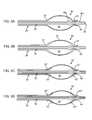
- FIG. 1is a side view of a first exemplary embodiment of an apparatus including a balloon for treating a body lumen, the apparatus operable in a first mode for minimizing a profile of the apparatus for introduction into the body lumen, a second mode for infusing fluid into the body lumen, and a third mode for removing material within the body lumen.
- FIG. 2is a side view of the apparatus of FIG. 1 in the first mode for minimizing a profile of the apparatus for introduction into a body lumen.
- FIG. 3is a side view of the apparatus of FIG. 1 in the second mode for infusing fluid into a body lumen.
- FIG. 4is a side view of the apparatus of FIG. 1 in the third mode in which the balloon is expanded for removing material within a body lumen.
- FIG. 5is a side view of the apparatus of FIGS. 1 and 4 in the third mode, showing a size of the balloon being increased to facilitate removing material within a body lumen.
- FIGS. 6A-6Dare side view details of the apparatus of FIGS. 1-5 , showing alternative configurations for the balloon.
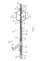
- FIG. 7is a side view of a second exemplary embodiment of an apparatus including a balloon for treating a body lumen, the apparatus operable in a first mode for infusing fluid into the body lumen, a second mode for dilating an obstruction within the body lumen, and a third mode for removing material within the body lumen.
- FIGS. 7A-7Hare cross-sections of the balloon of the apparatus of FIG. 7 , showing alternate constructions for integrally forming a helical member into the balloon.
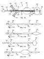
- FIG. 8is a side view of a third exemplary embodiment of an apparatus including a balloon for treating a body lumen, the apparatus operable in a first mode for dilating an obstruction within the body lumen, and a second mode for removing material within the body lumen.
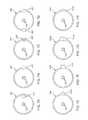
- FIGS. 9A-9Gare cross-sections of a body lumen showing exemplary methods for removing thrombus or other obstructive material from the body lumen and/or for dilating an obstruction within the body lumen using the apparatus of FIG. 7 or 8 .
- FIGS. 10A-10Dare cross-sectional views of alternative embodiments of balloon structures that may be provided on the apparatus of FIG. 8 to enhance removal of adherent material within a body lumen.
- FIG. 11is a side view of an alternative embodiment of the apparatus of FIG. 7 or 8 , including an obstruction removal balloon having different size coils in different regions of the balloon.
- FIGS. 12 and 13are cross-sectional views of a patient's body, showing methods for treating an arterio-venous dialysis graft using the apparatus of FIG. 11 .
- FIG. 14is a side view of another alternative embodiment of the apparatus of FIG. 11 , including a dilation balloon adjacent the obstruction removal balloon.
- FIGS. 15A and 15Bare alternative embodiments of coil structures that may be provided within the balloon of any of the apparatus of FIGS. 8-14 .
- FIG. 16is a side view of a fourth exemplary embodiment of an apparatus including a balloon for treating a body lumen, the apparatus operable in a first mode for removing material within the body lumen, and in a second mode for dilating an obstruction within the body lumen.
- FIGS. 17A-17Dare side views of the apparatus of FIG. 10 , showing operation of the apparatus between an initial delivery configuration ( FIG. 11A ), the first mode for removing material within a body lumen ( FIGS. 11B and 11C ), and the second mode for dilating an obstruction within a body lumen ( FIG. 11D ).
- FIG. 18is a side view of a distal end of another embodiment of a balloon catheter including a plurality of difference size balloons and a valve member for selectively delivering inflation media to one of the balloons.
- FIG. 19is a side view of an exemplary embodiment of an apparatus for removing obstructive material within a body lumen.
- FIG. 20is a detail of a handle of the apparatus of FIG. 19 .
- FIGS. 21A and 21Bare details of a distal end of the apparatus of FIG. 19 , showing lumen clearing elements being actuated between a low profile and a large profile, respectively.
- FIGS. 22A-22Fare cross-sectional views of a body lumen, showing a method for removing obstructive material within the body lumen using the apparatus of FIGS. 18-21B .
- FIG. 23Ais a perspective view of an apparatus, similar to that shown in FIG. 7 , including a first exemplary embodiment of a handle for actuating the apparatus.
- FIG. 23Bis a cross-sectional detail of components of a rotary knob control on the handle of FIG. 23A with a housing of the handle removed to show internal components.
- FIG. 24Ais a perspective view of another apparatus, similar to that shown in FIG. 7 , including a second exemplary embodiment of a handle for actuating the apparatus.
- FIG. 24Bis a cross-sectional detail of components of a slider control on the handle of FIG. 24A with a housing of the handle removed to show internal components.
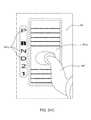
- FIG. 24Cis a detail of an alternate slider control, similar to that shown in FIGS. 24A and 24B , including visual indicators identifying actuatable positions of the apparatus.
- FIG. 25Ais a perspective view of yet another apparatus, similar to that shown in FIG. 7 , including a third exemplary embodiment of a handle for actuating the apparatus.
- FIG. 25Bis a cross-sectional detail of components of a rotary wheel control on the handle of FIG. 25A with a housing of the handle removed to show internal components.
- FIG. 26Ais a perspective view of still another apparatus, similar to that shown in FIG. 7 , including a fourth exemplary embodiment of a handle for actuating the apparatus.
- FIG. 26Bis a cross-sectional detail of components of a squeeze control on the handle of FIG. 26A with a housing of the handle removed to show internal components.
- FIGS. 1-5show a first exemplary embodiment of an apparatus 10 for treating a body lumen, e.g., for infusing fluid into a body lumen and/or for removing thrombus, objects, and/or obstructive material from within a body lumen, such as a blood vessel, aorto-venous fistula, tubular graft, and the like (not shown).
- the apparatus 10includes a catheter, sheath, or other tubular outer member 20 , a core wire, shaft, or other elongate inner member 30 , and an expandable balloon 50 carried by the inner and/or outer members 20 , 30 .
- the apparatus 10may be operable in multiple modes, for example, to perform various treatments or other functions within a body lumen, e.g., to reduce or eliminate the need to exchange multiple devices during a procedure within a body lumen.
- the apparatus 10may be operable in a first mode for minimizing a profile of the apparatus 10 , e.g., to facilitate introduction into a patient's body ( FIG. 2 ), a second mode for infusing fluid into a body lumen ( FIG. 3 ), and a third mode for removing material within a body lumen ( FIGS. 4 and 5 ), as described further below.
- the outer member 20includes a proximal end 22 , a distal end 24 sized for introduction into a body lumen, and a first lumen 26 extending therebetween.
- the outer member 20may have a substantially uniform construction along its length, or alternatively, the construction may be varied.
- a proximal portion of the outer member 20may be substantially rigid or semi-rigid to facilitate advancement of the apparatus 10 from the proximal end 22 and/or a distal portion of the outer member 20 may be flexible, e.g., to facilitate bending and/or advancement through tortuous anatomy without substantial risk of kinking or buckling.
- the outer member 20may be formed from materials such as metal, plastic, e.g., PEEK, Grilamed L25, and the like, or composite materials.
- the outer member 20may have a length between about thirty and one hundred thirty centimeters (30-130 cm) and an outer diameter between about 1.2 to 2.0 millimeters, and the first lumen 26 may have a diameter between about 1.0 and 1.8 millimeters.
- the inner member 30also includes a proximal end 32 , a distal end 34 , and, optionally, may include a second lumen 36 extending between the proximal and distal ends 32 , 34 , which may be sized to slidably receive a guide wire, or other rail (not shown) therethrough, e.g., having a diameter between about 0.3 and 1.0 millimeter.
- the inner member 30is sized to be slidably received within the first lumen 26 of the outer member 20 , e.g., such that an annular space is defined between the outer and inner members 20 , 30 for passing one or more fluids therethrough, as described further below.
- the inner member 30may have a length relative to the outer member 20 such that the inner member proximal end 32 is received within or extends proximally beyond the outer member proximal end 22 and the inner member distal end 34 extends distally beyond the outer member distal end 24 , e.g., through the balloon 50 , as described further below.
- the balloon 50includes a proximal end 52 coupled to the outer member distal end 24 , a distal end 54 defining an outlet 58 , and an interior 56 communicating with the first lumen 26 and the outlet 58 .
- the proximal end 52 of the balloon 50may be attached or otherwise secured to the distal end 24 of the outer member 20 to provide a fluid-tight connection, e.g., by one or more of bonding with adhesive, interference fit, sonic welding, fusing, engagement with a surrounding sleeve or other connector (not shown), and the like.
- the distal end 34 of the inner member 30may extend through the distal end 54 of the balloon 50 , e.g., such that the outlet 58 defines an annular passage between the distal end 54 of the balloon 50 and the distal end 34 of the inner member 30 .
- the size of the outlet 58may be substantially the same as the size of the first lumen 26 , or alternatively, the outlet 58 may be larger or smaller than the first lumen 26 , as desired, depending on the desired degree of friction or resistance to fluid flow through the outlet 58 .
- the resistance to fluid flowing through the outlet 58may be substantially less than the resistance of the balloon 50 to expansion, such that the fluid preferentially flows through the outlet 58 , rather than expanding the balloon 50 , as described further below.
- the distal end 54 of the balloon 50may be integrally formed with the main wall of the balloon 50 (defining the interior 56 ), and, optionally the proximal end 52 of the balloon 50 .
- the balloon 50 and its proximal and distal ends 52 , 54may be molded, blown, or otherwise formed from a single tubular section of material.
- the main wall of the balloon 50may be relatively thin compared to the distal end 54 , e.g., such that the distal end 54 of the balloon 50 maintains its original size and/or shape as the balloon 50 is expanded.
- the distal end 54 of the balloon 50may be sufficiently thick and/or rigid to provide a sealing ring on the distal end 54 .
- the distal end 54 of the balloon 50may include one or more additional features, e.g., surrounding or otherwise defining the outlet 58 and/or reinforcing the distal end 54 .
- the distal end 54may include a collar or sleeve (not shown, see, e.g., sleeve 155 shown in FIG. 7 ), within or around the distal end 54 e.g., attached or otherwise secured to the distal end 54 , e.g., by bonding with adhesive, interference fit, sonic welding, fusing, and the like.
- the balloon 50may be formed from elastic material, e.g., to provide a compliant or semi-compliant balloon that may be expanded to a variety of sizes and/or shapes, e.g., based on the amount of fluid and/or pressure within the interior 54 of the balloon 50 and/or the relative position of the inner member 30 , as described further below.
- the balloon 50may be formed from substantially inelastic material, e.g., to provide a non-compliant balloon that expands to a predetermined size when inflated independent of pressure (once a minimum volume and/or pressure is introduced to achieve the predetermined size).
- Such a non-compliant balloon 50may expand to the predetermined size even if inflated to relatively high pressures, e.g., until the balloon 50 bursts or otherwise ruptures, e.g., at pressures of ten atmospheres, twenty atmospheres, thirty atmospheres, and the like.
- One or more sealing members 38may be carried on the inner member distal end 34 , e.g., such that the sealing member(s) 38 are movable relative to the balloon 50 as the inner member 30 is moved, e.g., for selectively opening and closing the outlet 58 of the balloon 50 to provide a valve, as described further below.
- the sealing member(s) 38may be formed from flexible materials, e.g., which may enhance engagement with the balloon distal end 54 , such as elastomeric materials, e.g., silicone, or other plastics, e.g., PEBAX.
- a first sealing member 38 amay be provided on the inner member 30 proximal to or otherwise adjacent a second sealing member 38 b .
- the sealing member(s) 38may be disposed adjacent a distal tip 35 of the inner member 30 or may extend beyond the distal tip 35 .
- the distal tip 35(or the sealing member extending beyond the distal tip 35 ) may be substantially atraumatic, e.g., rounded, softened, provided with a “J” tip, and the like (not shown), to facilitate advancement of the apparatus 10 within a patient's body without substantial risk of the distal tip 35 puncturing or otherwise damaging walls of body lumens through which the distal tip 35 passes.
- the sealing member(s) 38may have a size, e.g., outer diameter, that is larger than the distal end 54 of the balloon 50 , e.g., larger than the inner diameter of the outlet 58 . As shown in FIG. 1 , the sealing members 38 are spaced apart sufficiently from one another such that the distal end 54 of the balloon 50 is free floating between the sealing members 38 . When the inner member 30 is directed axially, one of the sealing members 38 may engage or otherwise contact the distal end 54 of the balloon 50 .
- the sealing member(s) 38may have tapered shapes to facilitate seating or other engagement by the sealing member(s) 38 with the distal end 54 .
- the inner member 30may be directed distally to a first or distal position wherein the first sealing member 38 a pushes or otherwise contacts the distal end 54 , and the second sealing member 38 b is spaced from the balloon outlet 58 . As shown, the inner member 30 may be advanced distally to cause the first sealing member 38 a to push the distal end 54 . Because the outer diameter of the first sealing member 38 a is larger than inner diameter of the distal end 54 , the first sealing member 38 a pushes the distal end 54 of the balloon 50 away from the proximal end 52 tie, thereby stretching the balloon 50 .
- the first sealing member 38 amay substantially seal the outlet 58 , although alternatively, the first sealing member 38 a may include one or more axial grooves or other features that allow at least some fluid to pass through the outlet 58 even when the first sealing member 38 a is seated or pushing against the distal end 54 .
- the inner member 30may be directed axially to a second position, e.g., proximal to the first position, such that the distal end 54 of the balloon 50 is disposed between the sealing members 38 a , 38 b and the outlet 58 is substantially open.
- fluid introduced through the first lumen 26 of the outer member 20may pass through the balloon interior 56 and exit through the outlet 58 , e.g., between the balloon distal end 54 and inner member distal end 24 into the body lumen beyond the distal tip 35 .
- the inner member 30may also be directed proximally to a third position, e.g., proximal to the second position, in which the second sealing member 38 b engages the distal end 54 of the balloon 50 , thereby substantially sealing the outlet 58 from fluid flow therethrough.
- a third positione.g., proximal to the second position
- the inner member 30may be directed further proximally, e.g., to an indefinite number of positions wherein the second sealing member 38 b continues to seal the outlet 58 , and the size and/or shape of the expanded balloon 50 may be changed.
- FIG. 5the inner member 30 may be directed further proximally, e.g., to an indefinite number of positions wherein the second sealing member 38 b continues to seal the outlet 58 , and the size and/or shape of the expanded balloon 50 may be changed. For example, as shown in FIG.
- the balloon 50may be inflated to an elliptical or generally spherical shape, e.g., by delivering a predetermined volume of fluid into the interior 56 of the balloon 50 . If the balloon 50 is compliant, one of a range of desired volumes may be delivered into the interior 56 to expand the balloon 50 to a desired diameter.
- the distal end 54 of the balloon 50(captured between the sealing members 38 ) is also directed proximally, i.e., towards the proximal end 52 of the balloon 50 , thereby compressing the balloon 50 axially and expanding the balloon 50 further.
- the balloon 50 wallmay have a substantially uniform wall thickness between the proximal and distal ends 52 , 54 .
- the proximal and/or distal ends 52 , 54 of the balloon 50may at least partially evert into the interior 56 of the balloon 50 .
- the wall of the balloon 50may fold over onto the outside of the proximal and/or distal ends 52 , 54 as the inner member 30 is directed proximally from the third position.
- the thickness of the balloon 50 ′may be reduced along its length, e.g., thinning from the proximal and distal ends 52 ,′ 54 ′ towards a central region 55 ′ of the balloon 50 .
- the regions of the balloon 50 ′ immediately adjacent the proximal and distal ends 52 ,′ 54 ′may be relatively rigid compared to the central region 55 .
- the regions immediately adjacent the proximal and distal ends 52 ,′ 54 ′may resist the balloon 50 ′ everting and the thinner central region 55 ′ may expand to a greater diameter compared to the balloon 50 of FIG. 6A .
- the regions of the balloon 50 ,′′ 50 ′′′ immediately adjacent the proximal and/or distal ends 52 ,′′ 54 ′′ or 52 ,′′′ 54 ′′′′may be reinforced further, e.g., including additional materials, to reinforce the base of the balloon 50 ,′′ 50 ′′′ to reduce everting and/or otherwise preferentially control expansion of the balloon 50 ,′′ 50 .′′′
- composite materials 53 ′′have been embedded or otherwise provided in the balloon material adjacent the proximal and distal ends 52 ,′′ 54 ,′′ while in FIG.
- an additional layer of material 53 ′′′has been added, which may be the same material or different material than the rest of the balloon 50 .
- ′′′The layer may be attached to the balloon 50 ′′′ similar to the materials and methods described elsewhere herein for attaching the balloon 50 ′′′ to the outer member 20 .
- a handle or hub 60may be coupled to or otherwise provided on the proximal end 22 of the outer member 20 , e.g., for manipulating the outer member 20 and/or the entire apparatus 10 .
- the handle 60may have an ergonomic shape, e.g., to facilitate holding and/or manipulating the handle 60 , and including one or more controls or actuators for actuating the components of the apparatus 10 .
- a pull handle 62may be provided adjacent the main handle 60 that is coupled to the inner member 30 .
- the pull handle 62may be pushed or pulled, e.g., pushed distally to direct the inner member 30 to the first position shown in FIG.
- a slider actuator(not shown) may be provided on the handle 60 that is coupled to the inner member 30 for directing the inner member 30 axially relative to the handle 60 and outer member 20 .
- a wheel or other actuatormay be provided for directing the inner member 30 axially relative to the outer member 20 .
- the pull handle 62 and/or inner member 30may be biased to one of the positions shown in FIGS. 2-5 , e.g., by one or more springs or other biasing mechanisms (not shown) within the handle 60 .
- the inner member 30may be biased to the second (infusion) position, but may be directed to the other positions by overcoming the bias.
- the handle 60may include one or more features, e.g., pockets, notches, and the like (not shown), providing tactile feedback and/or for releasably securing the inner member 30 in one of the positions.
- the handle 60may include one or more visual markers (not shown), e.g., to inform the user when the various positions are achieved.
- the first sealing member 38 amay be eliminated and the first position eliminated, e.g., if there is less concern with profile of the apparatus 10 during introduction and/or to simplify operation of the apparatus 10 .
- the handle 60may also include one or more ports for coupling one or more fluid sources to the apparatus 10 , such as a source of inflation media, a source of vacuum, and/or a source of diagnostic and/or therapeutic agents (not shown).
- a side port 64may communicate with the first lumen 26 .
- the side port 64may include one or more connectors (not shown) to facilitate coupling one or more sources of fluid to the side port 64 , e.g., a Luer lock connector, and/or one or more seals, e.g., a hemostatic seal, to prevent fluid from leaking from the side port 64 .
- a syringe or other source of fluidmay be coupled to the side port 64 to allow delivery of the fluid through the first lumen 26 into the interior 56 of the balloon 50 and/or through the outlet 58 , depending upon the position of the inner member.
- contrast materiale.g., radiopaque, echogenic, or other fluid that facilitates observation using fluoroscopy, ultrasound, or other external imaging
- Such materialmay facilitate monitoring the apparatus 10 during advancement through a patient's body into a target body lumen and/or to identify the status of treatment of a body lumen, as described further below.
- the same fluidmay be delivered through the first lumen 26 to expand the balloon 50 , or the source of contrast material may be replaced with a source of a different fluid, e.g., a syringe of saline, to facilitate expansion and/or collapse of the balloon 50 .
- a source of a different fluide.g., a syringe of saline
- multiple portsmay be provided that communicate with the first lumen 26 , e.g., such that various fluids may be delivered selectively through the first lumen 26 depending upon the desired function.
- a source of contrast and a source of salinecould be coupled to different ports such that each fluid may be delivered independently depending upon the position of the inner member 30 without having to change out the sources.
- a source of one or more therapeutic agentsmay be coupled to the side port 64 (or to a separate port), e.g., when desired, to deliver the agent(s) into the target body lumen.
- the handle 60may include one or more seals, bushings, and the like to facilitate relative motion of the outer and inner members 20 , 30 and/or to seal the first lumen 26 .
- an o-ring 66may be provided between the outer and inner members 20 , 30 , which may guide the inner member 30 as it moves axially relative to the outer member 30 and handle 60 .
- the o-ring 66may also be located proximal to the side port 64 , thereby providing a substantially fluid-tight seal between the outer and inner members 20 , 30 to prevent leakage of fluid introduced into the side port 64 from the handle 60 .
- the pull handle 62includes a port 63 for receiving a guidewire or other rail (not shown) therethrough.
- a guidewiremay be introduced into the second lumen 36 , e.g., from the port 63 or by backloading into the inner member distal end 34 .
- the port 63may include one or more seals, e.g., a hemostatic seal (not shown), to accommodate passage of a guidewire through without risk of substantial risk of leakage of blood or other body fluids from the second lumen 36 .
- the outer member 20may include one or more additional lumens (not shown) extending between the proximal and distal ends 22 , 24 , e.g., a guidewire lumen for receiving a guidewire or other rail (not shown), e.g., if the inner member 30 does not include the second lumen 36 , an inflation lumen for delivering inflation media to another balloon (not shown) on the distal end 24 , and the like.
- additional lumensextending between the proximal and distal ends 22 , 24 , e.g., a guidewire lumen for receiving a guidewire or other rail (not shown), e.g., if the inner member 30 does not include the second lumen 36 , an inflation lumen for delivering inflation media to another balloon (not shown) on the distal end 24 , and the like.
- the apparatus 10may include one or more markers to facilitate positioning and/or advancement of the apparatus 10 during use.
- one or more radiopaque markersmay be placed on the outer member distal end 24 , on the inner member 30 within or adjacent the balloon 50 or distal tip 35 , on the balloon 50 , e.g., on the proximal and/or distal ends 52 , 54 , and/or on the sealing member(s) 38 .
- one or more components of the apparatus 10may be formed from radiopaque or other materials that may facilitate imaging the apparatus 10 during use.
- radiopaque markers and/or materialsmay facilitate positioning or otherwise imaging the apparatus 10 using fluoroscopy or other x-ray imaging, e.g., when positioning the balloon 50 (either before or after expansion) and/or when infusing fluid via the outlet 48 .
- echogenic markers and/or materialsmay be provided to facilitate imaging using ultrasound or similar imaging techniques.
- the target body lumenmay be a blood vessel, e.g., a vein or artery, a graft, e.g., an aorto-venous fistula, tubular xenograft, or synthetic tubular graft, and the like.
- the body lumenmay be a passage communicating between an adjacent artery and vein (not shown), e.g., in an arm or other region of a dialysis patient.
- the body lumenmay be a blood vessel within a patient's vasculature, e.g., a peripheral vessel in a patient's leg, a cerebral vessel, and the like.
- the materialmay be a stone within a patient's urinary tract or other foreign object to be removed from the patient's body.
- the body lumenmay be accessed using one or more additional instruments (not shown), which may be part of a system or kit including the apparatus 10 .
- additional instrumentsmay be part of a system or kit including the apparatus 10 .
- an introducer sheath, guide catheter, or other tubular membermay be introduced adjacent the target site where the material is to be removed, or may be introduced elsewhere in the patient's body to provide access to the patient's vasculature or other passages communicating with the body lumen.
- a percutaneous puncture or cut-downmay be created using a needle or other instrument (not shown) at a peripheral location, such as a femoral artery, carotid artery, or other entry site (also not shown), and an introducer sheath may be placed through the puncture at the peripheral location to provide access.
- the apparatus 10may be advanced through the patient's vasculature from the entry site, e.g., alone or with the aid of a guide catheter, guidewire, and the like (not shown).
- a guide catheter, micro-catheter, or other tubular bodymay be placed from the entry site to the body lumen using conventional methods.
- a guidewire(not shown) may be placed from the entry site to the body lumen if desired, e.g., if the inner member 30 includes the second lumen 36 .
- the tubular bodymay also be used for aspiration, e.g., coupled to a source of vacuum for capturing material removed by the apparatus 10 .
- the apparatus 10may be advanced into the body lumen with the inner member 30 in the second or distal position, e.g., such that the balloon 50 is stretched to reduce its profile.
- the first sealing member 38 adoes not seal the outlet 58
- one or more fluidsmay be delivered into the body lumen, e.g., to facilitate imaging and/or positioning the apparatus 10 .
- the inner member 30may be directed to the first position, shown in FIG. 3 , and fluid delivered to facilitate imaging.
- radiopaque contrast or other fluidmay be delivered into the body lumen via the annular passage defined by the first lumen 26 between the outer and inner members 20 , 30 to facilitate locating and/or measuring the size of the material 92 using fluoroscopy.
- Markers (not shown) on the apparatus 10may facilitate positioning the balloon 50 relative to material intended to be removed before the balloon 50 is expanded, e.g., to facilitate verifying that the balloon 50 is positioned distal to or otherwise beyond the material.
- the inner member 30may be directed back and forth between the first and second positions, e.g., to allow infusion of contrast and to reduce the profile of the apparatus 10 to facilitate further advancement, e.g., until the balloon 50 is located beyond obstructive material targeted for removal.
- the apparatus 10may be introduced through a guide catheter or other tubular member (not shown), that includes a lumen communicating with a source of vacuum.
- a guide catheter or other tubular memberthat includes a lumen communicating with a source of vacuum.
- the source of vacuummay be activated to aspirate material within the body lumen during the subsequent treatment.
- the inner member 30may be directed to the third position, thereby sealing the outlet 58 , and the balloon 50 may be inflated within the body lumen, e.g., such that the balloon 50 extends substantially entirely across the body lumen.
- the entire apparatus 10may then be retracted to pull the occlusive material from the body lumen, e.g., to be aspirated into guide catheter, or otherwise removed from the body lumen.
- the inner member 30may be pulled to further expand the balloon 50 , e.g., to substantially engage the wall of the body lumen.
- the additional pressure from the balloon 50may facilitate separating adherent material from the wall of the body lumen and allow its removal.
- the inner member 30may be directed back towards the second position, and fluid introduced to observe the amount of material removed and/or remaining within the body lumen. If additional material is to be removed, the inner member back be directed to the first position, e.g., if desired to advance the apparatus 10 through additional material to be removed. Once the balloon 50 is located beyond the material, the process may be repeated as often as desired.
- the obstructive materialmay be treated, e.g., at least partially dissolved, macerated, and the like before, during, or after withdrawal.
- a therapeutic agentmay be delivered into the body lumen via the first lumen 26 of the outer member 20 , e.g., to at least partially dissolve or separate thrombus or other relatively soft material before being removed by the balloon 50 and/or otherwise to treat the wall of the body lumen.
- the profile of the outer member 20 and therefore of the overall apparatus 10may be smaller than devices that include separate inflation and infusion lumens.
- the second lumen 36 of the inner member 30could be used for infusion of fluids, this would generally require removing the guidewire over which the apparatus 10 is introduced since the guidewire may substantially fill the second lumen 36 .
- the guidewiremay remain within the second lumen 36 throughout the procedure, thereby potentially reducing the number of guidewire or other device exchanges. Further, the apparatus 10 may remain over the guidewire, which may facilitate advancing the apparatus 10 to other target body lumens intended for treatment.
- valve created by the sealing member(s) 38 and the outlet 58 of the balloon 50may be provided at other locations on the apparatus 10 , if desired.
- the configurationmay be reversed such that the outlet 58 and sealing members 38 may be located proximal to the balloon 50 .
- a sealing member(not shown) may be provided on the distal end 24 of the outer member 20 , and the proximal end 52 of the balloon 50 may float adjacent the sealing member(s), with the distal end 54 of the balloon 50 is secured to the distal end 34 of the inner member 30 (also not shown).
- movement of the inner member 30 relative to the outer member 20may cause the balloon proximal end to selectively engage or disengage the sealing member(s), allowing infusion from the first lumen 24 when the balloon proximal end is not engaged with the sealing member(s) and allowing balloon inflation when the balloon proximal end engages the sealing member(s).
- a balloonmay be provided on the distal end 24 of the outer member 20 proximal to the balloon 50 and/or on the distal end 34 of the inner member 30 distal to the balloon 50 , if desired, similar to other embodiments described herein.
- a balloonmay be a non-compliant, high pressure balloon, e.g., for dilating the body lumen, or an elastic, compliant balloon for substantially sealing the body lumen to isolate one or more regions of the body lumen before infusion of fluid therein.
- FIG. 7another embodiment of an apparatus 110 is shown for treating a body lumen that generally includes an outer tubular member 120 , an inner member 130 , and an expandable balloon 150 carried by the inner and/or outer members 120 , 130 , similar to the previous embodiments.
- the apparatus 110may be operable in a first mode for infusing fluid into a body lumen, a second mode for dilating an obstruction within a body lumen, and/or a third mode for removing obstructive material within a body lumen, as described further below.
- the outer member 120includes a proximal end 122 , a distal end 124 sized for introduction into a body lumen, and a first lumen 126 extending therebetween, which may be constructed similar to the previous embodiments.
- the inner member 130also includes a proximal end 132 , a distal end 134 , and, optionally, a second lumen 136 extending between the proximal and distal ends 132 , 134 , e.g., sized to slidably receive a guide wire, or other rail (not shown) therethrough.
- the inner member 130is sized to be slidably received within the first lumen 126 of the outer member 120 , e.g., such that an annular space is defined between the outer and inner members 120 , 130 for passing one or more fluids therethrough, also similar to the previous embodiments.
- the balloon 150includes a proximal end 152 coupled to the outer member distal end 124 , a distal end 154 defining an outlet 158 , and an interior 156 communicating with the first lumen 126 and the outlet 158 .
- the distal end 134 of the inner member 130may extend through the distal end 154 of the balloon 150 , e.g., such that the outlet 158 defines an annular passage between the distal end 154 of the balloon 150 and the distal end 134 of the inner member 130 .
- the distal end 154 of the balloon 150includes a collar or sleeve 155 attached or otherwise secured to the distal end 154 , e.g., by bonding with adhesive, interference fit, sonic welding, fusing, and the like.
- the collar 155may extend proximally into the interior 156 of the balloon 150 (not shown) and the interior section of the collar 155 may include one or more side ports or other openings (also not shown), e.g., to facilitate fluid passing from the balloon interior 156 through the outlet 158 .
- the balloon 150may be formed from substantially inelastic material, e.g., to provide a non-compliant balloon that expands to a predetermined size when inflated independent of pressure (once a minimum volume is introduced to achieve the predetermined size). Such a non-compliant balloon 150 may expand to the predetermined size even if inflated to relatively high pressures, e.g., until the balloon 150 bursts or otherwise ruptures, e.g., at pressures of ten atmospheres, twenty atmospheres, thirty atmospheres, and the like. Alternatively, the balloon 150 may be formed from elastic material, similar to other embodiments described elsewhere herein.
- One or more sealing members 138may be carried on the inner member distal end 134 , e.g., such that the sealing member(s) 138 are movable relative to the balloon 150 as the inner member 130 is moved, e.g., to provide a valve for selectively opening and closing the outlet 158 of the balloon 150 .
- a first sealing member 138is provided on the inner member 130 distal to the balloon distal end 154 and collar 155 .
- the sealing member 138may have a size, e.g., outer diameter, that is larger than the collar 155 and distal end 154 of the balloon 150 such that the sealing member 138 may substantially engage the collar 155 and/or distal end 154 of the balloon 150 to substantially seal the outlet 158 .
- the sealing member 138may include a tapered shape, e.g., on one or both of its proximal and distal ends.
- a tapered shape on the proximal end of the sealing member 138may automatically guide the sealing member 138 into being seated in the outlet 158 of the balloon 150 , e.g., to enhance a fluid-tight seal therebetween.
- a tapered shape on the distal end of the sealing member 138may provide a rounded or otherwise substantially atraumatic tip for the apparatus 110 .
- a substantially atraumatic distal tip(not shown) may be provided on the inner member 130 beyond the first sealing member 138 , similar to the previous embodiments.
- a handle or hub 160may be coupled to or otherwise provided on the proximal end 122 of the outer member 120 , e.g., for manipulating the outer member 120 and/or the entire apparatus 110 , generally similar to the previous embodiments.
- the handle 160may include a pull handle 162 or other actuator coupled to the inner member 130 for moving the inner member 130 to the various positions described below.
- the handle 160may also include one or more ports, such as port 163 and side port 164 for coupling one or more fluid sources to the apparatus 110 , e.g., a syringe or other source of fluid for delivering fluid through the first lumen 126 into the interior 156 of the balloon 150 and/or through the outlet 158 , depending upon the position of the inner member 130 .
- one or more fluid sourcese.g., a syringe or other source of fluid for delivering fluid through the first lumen 126 into the interior 156 of the balloon 150 and/or through the outlet 158 , depending upon the position of the inner member 130 .
- the handle 160may include one or more seals, bushings, and the like, such as o-ring 166 , between the outer and inner members 120 , 130 , which may guide the inner member 130 as it moves axially relative to the outer member 130 and handle 160 .
- the inner member 130includes a section of hypotube or other substantially rigid tubing 131 attached or otherwise coupled to the proximal end 132 of the inner member 130 .
- the tubing 131may provide axial support for the inner member 130 , e.g., to prevent buckling or kinking when the inner member 130 is directed axially.
- the tubing 131may also allow the inner member 130 to move axially more easily, e.g., if the tubing 131 has a substantially smooth or lubricated outer surface that slides easily through the o-ring 166 while maintaining a fluid-tight seal therebetween.
- the apparatus 110may include one or more markers to facilitate positioning and/or advancement of the apparatus 110 during use.
- radiopaque marker bands 137may be attached around the distal end 134 of the inner member 130 , e.g., within the balloon interior 56 .
- a marker 137is attached adjacent both the proximal end 152 and the distal end 154 of the balloon 150 , which may facilitate monitoring the location of the balloon 150 before dilating an obstruction within a body lumen.
- a core wire of the helical member 170may be formed from radiopaque material, and/or radiopaque filler material, BAS04, may be dispersed into plastic material used to form the helical member 170 , if desired.
- the apparatus 110includes a helical member 170 coupled between the outer and inner members 120 , 130 within the balloon interior 156 .
- the helical member 170may be movable from a relatively low profile, such as that shown in FIG. 7 , to an expanded helical shape, as described further below.
- the helical member 170is a wire, tube, or other filament including a first end 172 coupled to the distal end 124 of the outer member 120 and a second end 174 coupled to the distal end 134 of the inner member 130 .
- the helical member 170may be from a core wire having a tube or sleeve formed or attached around the wire (not shown).
- the helical member 170may wrap helically around the inner member 130 one or more times. As shown, the helical member 170 extends around the inner member 130 about one and a half turns, although it will be appreciated that the helical member 170 may include more or fewer turns.
- the first end 172 of the helical member 170may be attached or otherwise secured directly to the distal end 124 of the outer member 120 , e.g., by one or more of bonding with adhesive, sonic welding, soldering, interference fit (e.g., by wrapping the first end 172 one or more times around the distal end 124 ), inserting the first end 172 into an annular groove, hole, or pocket (not shown) in the distal end 124 , fusing, and the like.
- the second end 174 of the helical member 170may be similarly attached or otherwise secured to a sleeve 178 fixed to the distal end 134 of the inner member 130 or directly to the distal end 134 .
- the sleeve 178may be a relatively short tube attached to the inner member distal end 134 adjacent the balloon distal end 154 , e.g., by bonding with adhesive, sonic welding, interference fit, fusing, and the like.
- the sleeve 178may have an outer diameter larger than the inner diameter of the collar 155 and/or distal end 154 of the balloon 150 , thereby providing a stop that limits movement of the collar 155 and distal end 154 relative to the inner member 130 .
- the sleeve 178When the sleeve 178 contacts the collar 155 and/or distal end 154 , the sleeve 178 may not substantially obstruct the annular passage communicating with the outlet 158 , e.g., such that fluid may still flow through the outlet 158 when introduced into the balloon interior 156 .
- the sleeve 178may be shaped to substantially seal the outlet 158 when the sleeve 178 engages the collar 155 and/or distal end 154 of the balloon 150 , similar to the other sealing members described elsewhere herein.
- the collar 155may be positioned between the sealing member 138 and the sleeve 178 when the collar and sleeve 178 are attached to the inner member distal end 134 , i.e., before attaching the collar 155 to the balloon distal end 154 .
- the balloon distal end 154may then be attached over the collar 155 when the balloon 154 is attached to the outer member distal end 124 .
- the balloon distal end 154may be attached to the collar 155 such that a proximal section of the collar 155 is disposed within the interior 156 of the balloon 150 .
- the proximal section of the collar 155may include one or more openings (not shown) to facilitate fluid passing from the balloon interior 156 through the collar 155 and out the outlet 158 , i.e., when the outlet 158 is not sealed by the sealing member 138 , as described further below.
- the inner member 130may be movable axially relative to the outer member 120 , e.g., between a first or distal position, a second or intermediate position (shown in FIG. 7 ), and/or a third or proximal position (not shown), thereby allowing the apparatus 110 to provide different functions for treating a body lumen.
- the inner member 130may direct the sealing member 138 distally such that the sealing member 138 is spaced apart from the balloon outlet 158 .
- fluid introduced through the first lumen 126 of the outer member 120may pass through the balloon interior 156 and out the outlet 158 , e.g., into the body lumen beyond the distal tip 35 , similar to the previous embodiments.
- the inner member 130may be directed proximally to a second position, such as that shown in FIG. 7 , in which the sealing member 138 engages the collar 155 and/or distal end 154 of the balloon 150 , thereby substantially sealing the outlet 158 from fluid flow therethrough.
- a second positionsuch as that shown in FIG. 7
- the sealing member 138engages the collar 155 and/or distal end 154 of the balloon 150 , thereby substantially sealing the outlet 158 from fluid flow therethrough.
- any fluid introduced through the first lumen 126enters the balloon interior 156 and may expand the balloon 150 .
- the balloon 150may be expanded to an elongate substantially cylindrical shape, e.g., having a substantially uniform diameter main portion between tapered end portions.
- the main portion of the balloon 150may have a length between about twenty and eighty millimeters (20-80 mm) and a diameter between about three and twelve millimeters (3-12 mm).
- the balloon 150may be used to dilate or otherwise apply substantial pressure to a wall of a body lumen, e.g., for dilating a stenosis, lesion, or other obstruction, similar to the method shown in FIGS. 9E-9G and described further below.
- a source of vacuummay be coupled to the side port 164 and the balloon 150 collapsed to a contracted condition around the helical member 170 .
- a source of vacuummay be coupled to the side port 164 and the balloon 150 collapsed to a contracted condition around the helical member 170 .
- the balloon 150has not been previously inflated, it may not be necessary to collapse the balloon 150 using vacuum since the balloon 150 may already be sufficiently collapsed or otherwise remain in the contracted condition.
- the inner member 130may then be directed proximally to the third position, thereby directing the ends of the helical member 170 towards one another. This causes the helical member 170 to expand radially outwardly as it is compressed axially, thereby causing the balloon 150 also to compress axially and expand radially into an expanded helical shape around the helical member 170 , e.g., as shown in FIG. 7A .
- the inner member 130 and/or handle 150may include one or more stops (not shown) that limit proximal movement of the inner member 130 when compressing and expanding the balloon 150 and helical member 170 .
- the stop(s)may allow the inner member 130 to be pulled until the balloon length is reduced to between about six and thirty millimeters (6-30 mm), thereby preventing overcompression of the balloon 150 and/or helical member 170 .
- the helical member 170may have sufficient rigidity that the helical member 170 may simply buckle elastically from the low profile towards the helical shape as it is compressed axially. Thus, the helical member 170 may expand without substantial plastic deformation such that the helical member 170 may be returned to its original low profile shape (and expanded and collapsed repeatedly, if desired).
- the helical member 170may be biased to a predetermined expanded helical shape but may be constrained in the low profile, e.g., by providing axial tension on the ends 172 , 174 of the helical member 170 when the inner member 130 is in the first or second positions. As the inner member 130 is directed towards the third position, the tension may be released, whereupon the helical member 170 may resiliently expand towards the expanded helical shape.
- the helical membermay be integrally formed or otherwise coupled directly to the balloon 150 , e.g., attached to, embedded within, or otherwise secured to the balloon wall (not shown) between the proximal and distal ends 152 , 154 .
- one or more helically shaped wires or fibers 157 ′may be molded, embedded, or integrally formed in the wall of the balloon 150 .′
- the fiber(s) 157 ′may automatically bias the balloon 150 ′ towards the expanded helical shape.
- a fiber 157 ′′may be molded, embedded, or integrally formed in the wall of the balloon 150 ′′ that includes a core wire or member 159 ,′′ e.g., a radiopaque material, a biased core wire, and the like.
- FIGS. 7E-7Hshow alternate shapes and/or configurations for a fiber 157 e to 157 h or other stiffening features that may be molded, embedded, or otherwise integrally formed in the wall of the balloon 150 e to 150 h and extend helically between proximal and distal ends of the balloon 150 e to 150 h .
- the fiber(s) and/or stiffening featuresmay include one or more turns between the proximal and distal ends of the balloon 150 ′, 150 ′′, or 150 e to 150 h , e.g., one and a half, two, three, four, or more turns.
- any of the fibers and/or stiffening features included on a balloonmay provide cutting edges or elements, e.g., that may be at least partially embedded into a wall of a body lumen when the balloon 150 ′, 150 ′′, or 150 e to 150 h is inflated to dilate an obstruction in a body lumen.
- the entire apparatus 110may be directed along a body lumen, e.g., to remove obstructive material including scraping, scrubbing, or otherwise separating adherent material from a wall of the body lumen, if desired, similar to the method shown in FIGS. 9A-9D and described further below.
- a single balloon 150may be used for both dilation, e.g., using relatively high pressures, and for scraping, scrubbing, or otherwise removing obstructive material within a body lumen.
- an apparatus 110 ′is shown that is generally similar to the apparatus 110 of FIG. 7 , i.e., including a balloon 150 ′ and a helical member 170 ,′ except that the apparatus 110 ′ includes an alternative embodiment of a handle 760 on the proximal end 122 ′ of the outer member 120 .
- the handle 760includes an outer housing 761 (shown in FIG. 23A ), an inner carriage 765 (shown in FIG. 23B ) slidable axially within the housing 761 , a rotary knob 762 carried by the housing 761 and coupled to the carriage 765 , and a hub 763 extending from the housing 761 .
- the housing 761may include one or more pieces, e.g., one or more sets of mating halves or clamshells (not shown) that may be connected together, e.g., along a longitudinal seam (also not shown) to provide the housing 761 , e.g., secured together by mating connectors, bonding with adhesive, sonic welding, fusing, and the like.
- the housing 761may include a slot, track or other features (not shown) that allow the carriage 765 to slide axially within the housing 761 without substantial lateral movement.
- the housing 761 and/or carriage 765may include one or more cooperating features, e.g., stops (not shown) within the housing 761 that limit axial movement of the carriage 765 relative to the housing 761 , for example, to limit movement of the inner member 130 ′ between the first position (for infusion from the outlet 158 ′) and the third position (where the balloon 150 ′ is directed to an expanded helical shape, not shown).
- stopse.g., stops within the housing 761 that limit axial movement of the carriage 765 relative to the housing 761 , for example, to limit movement of the inner member 130 ′ between the first position (for infusion from the outlet 158 ′) and the third position (where the balloon 150 ′ is directed to an expanded helical shape, not shown).
- the housing 761may include a side port 764 , e.g., including a Luer lock or other connector, for connecting a source of fluid to the apparatus 110 .′
- the side port 764may communicate with a lumen extending through the outer member 120 ′ for delivering fluid into the interior of the balloon 150 ,′ similar to the previous embodiments.
- the knob 762may include an outer portion 762 a surrounding or otherwise extending radially from the housing 761 , e.g., including ridges or other features to facilitate rotation or other manipulation of the knob 762 during use, and an inner stem 762 b that extends axially along a first passage 765 a within the carriage 765 .
- the inner stem 762 b and the carriage 765may include cooperating features, e.g., helical threads 762 c , that translate rotation of the knob 762 into axial movement of the carriage 765 .
- the knob 762may be substantially fixed axially relative to the housing 761 and freely rotatable about a longitudinal axis of the apparatus 110 .′
- the proximal end 132 ′ of the inner member 130 ′may pass freely through the inner stem 762 b and be fixed relative to the carriage 765 .
- the inner member proximal end 132 ′may be secured to the carriage 765 by fixing the proximal end 132 ′ in a second passage 765 b adjacent to and/or communicating with the first passage 765 a , e.g., bonding with adhesive, sonic welding, fusing, interference fit, mating connectors (not shown), and the like.
- axial movement of the inner member 130 ′may be coupled to movement of the carriage 765 .
- the hub 763may include a hypotube or other tubular member 763 a and a Luer lock or other connector 763 b secured to one another and/or to the outer housing 761 .
- a proximal end of the tubular member 763 a and/or the connector 763 bmay be attached to a proximal end of the housing 761 , e.g., by bonding with adhesive, sonic welding, fusing, interference fit, mating connectors (not shown), and the like.
- the tubular member 763 amay be slidably received in the second passage 765 b such that the tubular member 763 a and connector 763 b remain substantially stationary relative to the housing 761 as the carriage 765 is directed axially.
- One or more sealse.g., o-ring 766 , may be provided within or around the second passage 765 b that allow the tubular member 763 a to slide therethrough while providing a fluid-tight seal that prevents fluid from leaking through the passages 765 a , 765 b and out of the housing 761 .
- the knob 762may be rotated in a first direction, thereby translating the inner member 130 ′ distally to the first position to open the outlet 158 .′
- fluid delivered through the outer member 120 ′may pass through the balloon 150 ′ and exit the outlet 158 ,′ as described above.
- the knob 762may be rotated in a second opposite direction, thereby translating the inner member 130 ′ proximally to the second position, e.g., until the sealing member 138 ′ seals the outlet 158 ′ to allow balloon expansion, and/or further to the third position, e.g., to expand the balloon 150 ′ to the expanded helical shape, also as described above.
- the knob 762 and/or housing 761may include visual, audible, or other indicators (not shown) that identify the direction to rotate the knob 762 to achieve the desired position(s) and/or that indicate when a particular position is achieved, e.g., by aligning an arrow (not shown) on the knob 762 with respective indicators (also not shown) that identify the first, second, and/or third positions.
- the apparatus 110 ′may operate similar to the previous embodiments.
- FIGS. 24A-24Canother embodiment of a handle 860 is shown that includes an outer housing 861 with a side port 864 (shown in FIG. 24A ), an inner carriage 865 (shown in FIG. 24B ) slidable axially within the housing 861 , and a hub 863 extending from the housing 861 , generally similar to the handle 760 .
- the housing 861may include one or more pieces, e.g., one or more sets of mating halves or clamshells (not shown) that may be connected together and may include a slot, track or other features (not shown) that allows the carriage 865 to slide axially within the housing 861 , e.g., without substantial lateral movement.
- the housing 861 and/or carriage 865may include one or more features that limit axial movement of the carriage 865 relative to the housing 861 , e.g., to limit movement of the inner member 130 ′ between the first position (for infusion from the outlet 158 ′), second position (for balloon inflation), and the third position (where the balloon 150 ′ is directed to an expanded helical shape, not shown).
- the proximal end 132 ′ of the inner member 130 ′is substantially fixed relative to the carriage 865 , e.g., by fixing the proximal end 132 ′ in a passage 865 a adjacent to a distal end of the carriage 865 , for example, bonding with adhesive, sonic welding, fusing, interference fit, mating connectors (not shown), and the like.
- axial movement of the inner member 130 ′may be coupled to movement of the carriage 865 .
- the hub 863may include a hypotube or other tubular member 863 a and a Luer lock or other connector 863 b secured to one another and/or to the outer housing 861 .
- a proximal end of the tubular member 863 a and/or the connector 863 bmay be attached to a proximal end of the housing 861 , e.g., by bonding with adhesive, sonic welding, fusing, interference fit, mating connectors (not shown), and the like.
- the tubular member 863 amay be slidably received in the passage 865 a , e.g., adjacent a proximal end of the carriage 865 , such that the tubular member 863 a and connector 863 b remain stationary relative to the housing 861 (and inner member proximal end 132 ′) as the carriage 865 is directed axially.
- a guidewire or other instrument, backloaded through the inner member 130 ′may pass freely through the passage 865 a , tubular member 863 a , and out the connector 863 b (or inserted through the connector 863 b into the inner member 130 ′).
- One or more sealsmay be provided within or around the passage 865 a that allow the tubular member 863 to slide therethrough while providing a fluid-tight seal that prevents fluid from leaking through the passage 865 a out of the housing 861 .
- the handle 860includes a push button 862 carried by the housing 861 and coupled to the carriage 865 .
- the housing 861may include an elongate slot 861 a and the push button 862 may be slidable axially within the slot 861 a .
- the slot 861 amay include one or more pockets or detents 861 b that may capture the push button 862 , e.g., to releasably secure the push button 862 , and consequently the carriage 865 and inner member 130 ,′ in one or more positions.
- the housing 861may include one or more visual indicators, e.g., for identifying the position of the inner member 132 ′ when the push button 862 is received in a particular pocket 861 b .
- the housing 861may include numbers or other symbols 861 c aligned with respective pockets (not shown) such that when the push button, in this embodiment, lever 862 is aligned with a particular symbol 861 c , the user can confirm that the inner member 130 ′ is in a respective particular position.
- the push button 862may include a base 862 a substantially fixed relative to the carriage 865 and a cap 862 b slidable laterally relative to the base 862 a .
- the base 862 amay be integrally molded or otherwise formed with the carriage 865 and the cap 862 b may be attached to the base 862 a such that the cap 862 b may be slid laterally, e.g., substantially perpendicular to the longitudinal axis of the handle 860 .
- the cap 862 bmay be biased such that the cap 862 b may automatically slide into a pocket 861 b with which the cap 862 b is aligned, yet the bias may be overcome to move the cap 862 b out of the respective pocket 861 b into the slot 861 a so that the cap 862 b may be slid axially into another pocket 861 b .
- a spring or other biasing mechanism(not shown) may be provided within the cap 862 b or housing 861 that may push the cap 862 b laterally from the base 862 a.
- the entire push button 862may be fixed relative to the carriage 865 , e.g., integrally molded or formed together, and the push button 862 and carriage 865 may be pivoted about the longitudinal axis to allow the cap 862 b to be directed out of a particular pocket 861 b , directed axially along the slot 861 a , and released or otherwise placed in another pocket 861 b .
- a spring or other biasing mechanismmay bias the push button 862 and carriage 865 to direct the cap 862 b into any pocket 861 b with which the cap 862 b is aligned when the cap 862 b is released.
- the handle 860may include three pockets 861 b , e.g., one corresponding to the first position of the inner member 130 ,′ one corresponding to the second position, and one corresponding to the third position.
- the cap 862 bmay be directed out of a pocket within which the cap 862 b is received, the push button 862 may be slid axially along the slot 861 a , and released or otherwise directed into the desired pocket 861 b .
- the handle 860may include only one or two pockets 861 b , e.g., if the push button 862 is biased axially to one of the positions.
- the push button 862may be directed axially in a first direction, e.g., distally to the indicator “R” in FIG. 24C , and released or captured in a corresponding pocket, thereby translating the inner member 130 ′ distally to the first position to open the outlet 158 .′
- fluid delivered through the outer member 120 ′may pass through the balloon 150 ′ and exit the outlet 158 ,′ as described above.
- the push button 862may be directed out of the pocket and directed axially, e.g., proximally, to the indicator “N”, thereby translating the inner member 130 ′ proximally to the second position, e.g., until the sealing member 138 ′ seals the outlet 158 ′ to allow balloon expansion.
- the push member 872may be directed out of the “N” pocket, axially within the slot 861 a , and released in the third pocket, corresponding to indicator “D,” thereby translating the inner member 130 ′ to the third position, e.g., to expand the balloon 150 ′ to the expanded helical shape, also as described above.
- FIGS. 25A and 25Bstill another embodiment of a handle 960 is shown that includes an outer housing 961 including a side port 964 (shown in FIG. 25A ), a carriage (not shown) within the housing 961 , and a hub 963 extending from the housing 961 , generally similar to the previous embodiments.
- the carriagemay include a rack 965 (shown in FIG. 25B ) including a plurality of teeth 965 a spaced apart axially along the rack 965 .
- the proximal end (not shown) of the inner member 130 ′may be substantially fixed relative to the carriage (not shown) such that axial movement of the inner member 130 ′ is coupled to movement of the carriage and consequently to the rack 965 , similar to the previous embodiments.
- the hub 963may include a hypotube or other tubular member (not shown) and a Luer lock or other connector 963 b secured to one another and/or to the outer housing 961 , similar to the previous embodiments.
- the tubular membermay be slidably received in a passage in the carriage, e.g., such that the connector 963 b remains substantially stationary relative to the housing 961 (and inner member 130 ′) as the carriage is directed axially.
- the actuatoris a rotary wheel 962 rotatably mounted to the housing 961 , as shown in FIG. 25A .
- the rotary wheel 962includes an outer wheel 962 a including ridges or other features to facilitate engaging and/or rotating the rotary wheel 962 , and a pinion 962 b that extends into the housing 961 . As best seen in FIG.
- teeth on the pinion 962 bmay interlock with the teeth 965 a on the rack 965 such that rotation of the outer wheel 962 a causes the rack 965 , and consequently, the inner member 130 ,′ to move axially relative to the housing 961 and outer member 120 .
- the housing 961may include one or more visual indicators, e.g., for identifying the position of the inner member 132 ′ when the wheel 962 a is rotated to one or more orientations, similar to the previous embodiments.
- the rotary wheel 962may be rotated in a first direction, e.g., to translate the inner member 130 ′ distally to the first position to open the outlet 158 .′
- the rotary wheel 962may be rotated in a second opposite direction to translate the inner member 130 ′ proximally to the second position and/or third position, e.g., to allow inflation of the balloon 150 ′ and/or expanding the balloon 150 ′ and helical member 170 ′ to the expanded helical shape, similar to the previous embodiments.
- One advantage of the rotary wheel 962is that the ratio of the outer wheel 962 a , pinion 962 b , and teeth 965 on the rack 965 may be designed to provide a desired mechanical advantage and/or precision of movement of the inner member 130 .′
- FIGS. 26A and 26BAnother embodiment of a handle 1060 is shown in FIGS. 26A and 26B that may be included in any of the apparatus shown herein. Similar to the previous embodiments, the handle 1060 includes a housing 1061 including a hub 1063 and a side port 1064 . In this embodiment, the actuator is a squeeze button 1062 that may be depressed to direct the inner member 130 ′ axially. e.g., from a first position to a second position, similar to the embodiments described elsewhere herein.
- links 1062 a , 1062 b defining the button 1062are flattened out, thereby directing the proximal link 1062 a proximally if the distal link 1062 b is fixed axially relative to the housing 1061 .
- a first end of the distal link 1062 bmay be pivotally coupled to the housing 1061 and a second end pivotally coupled to a first end of the proximal link 1062 .
- a second end of the proximal link 1062 amay be slidable axially along the housing 861 , e.g., within a slot or track (not shown).
- the proximal link 1062With the second end of the proximal link 1062 a coupled to the inner member 130 ,′ e.g., by a cable or other linkage 1062 c , as the squeeze button 1062 is pressed inwardly, the proximal link 1062 pulls the inner member 130 ,′ e.g., from a first position (with the outlet 158 ′ open) to a second position (allowing the balloon 158 ′ to be inflated and/or expanded to the expanded helical shape).
- a covermay be placed over the squeeze button 1062 to protect the user from catching anything between the links 1062 a , 1062 b .
- the squeeze button 1062may be provided on the top of the housing 1061 (as shown), e.g., to allow a user to actuate the squeeze button 1062 with their thumb, or on the bottom of the housing 1061 (not shown), e.g., to allow a user to actuate the squeeze button 1062 with their index finger.
- the handle 1060may include one or more features (not shown) to allow the squeeze button 1062 to be releasably secured at one or more positions before the links 1062 a , 1062 b are completely flattened, e.g., to allow the inner member 130 ′ to be translated and fixed in different positions, e.g., successively in the second and third positions, similar to the previous embodiments.
- FIG. 8still another embodiment of an apparatus 210 is shown for treating a body lumen that generally includes an outer tubular member 220 , an inner member 230 , and an expandable balloon 250 , and helical member 270 carried by the inner and/or outer members 220 , 230 , similar to the previous embodiments, but does not include a valve for opening or closing an outlet in the balloon, unlike the embodiment of FIG. 7 .
- the apparatus 110may be operable in a first mode for dilating an obstruction within a body lumen, and/or a second mode for removing obstructive material within a body lumen, as described further below.
- the outer member 220includes proximal and distal ends 222 , 224 , and a first lumen 226 extending therebetween
- the inner member 230also includes proximal and distal ends 232 , 234 , and a second lumen 236 extending therebetween.
- the inner member 230is sized to be slidably received within the first lumen 226 of the outer member 220 , e.g., such that an annular space is defined between the outer and inner members 220 , 230 for passing one or more fluids therethrough, also similar to the previous embodiments.
- a handle or hub 260may be coupled to or otherwise provided on the proximal end 222 of the outer member 220 , e.g., including a pull handle or other actuator 262 for moving the inner member 230 relative to the outer member 220 , a side port 264 for coupling one or more fluid sources to the apparatus 210 , and an o-ring or other seal 166 between the outer and inner members 220 , 230 , which may also be similar to the previous embodiments.
- the balloon 250includes a proximal end 252 coupled to the outer member distal end 224 , a distal end 254 coupled to the inner member distal end 234 , e.g., attached by bonding with adhesive, interference fit, sonic welding, fusing, and the like, similar to the previous embodiments.
- the balloon 250may be formed from substantially inelastic material, e.g., to provide a non-compliant balloon that expands to a predetermined size when inflated independent of pressure, or alternatively, the balloon 250 may be formed from elastic material, similar to the other embodiments described elsewhere herein.
- the helical member 270is coupled between the outer and inner members 220 , 230 .
- the helical member 270may be movable from a relatively low profile, such as that shown in FIG. 8 , to an expanded helical shape, as described further below with reference to FIGS. 9A-9D .
- a first end 272 of the helical member 270may be attached or otherwise secured directly to the distal end 224 of the outer member 220 and a second end 274 of the helical member 270 may be attached or otherwise secured to the distal end 234 of the inner member 230 adjacent the balloon distal end 252 .
- the apparatus 210may be used for treating a body lumen 90 , e.g., for removing obstructive material 92 and/or dilating an obstruction 94 within a body lumen 90 , e.g., as shown in FIG. 9A .
- the target body lumen 90may be a blood vessel, e.g., a vein or artery, a graft, e.g., an aorto-venous fistula, tubular xenograft, or synthetic tubular graft, and the like.
- the body lumenmay be accessed using one or more additional instruments (not shown), which may be part of a system or kit including the apparatus 210 , e.g., including one or more introducer sheaths, guide catheters, and/or guidewires (not shown).
- additional instrumentsmay be part of a system or kit including the apparatus 210 , e.g., including one or more introducer sheaths, guide catheters, and/or guidewires (not shown).
- a guide catheter, micro-catheter, introducer sheath, or other tubular bodymay be placed from the entry site to the body lumen 90 using conventional methods.
- a guidewire(not shown) may be placed from the entry site to the body lumen 90 if desired.
- the apparatus 210may be advanced into the body lumen 90 with the inner member 230 in the first or distal position, e.g., such that the balloon 250 is substantially collapsed.
- contrast or other fluidmay be delivered into the body lumen 90 , e.g., via the second lumen 236 in the inner member 230 (not shown, see FIG. 8 ) or via a separate lumen (not shown) in the outer member 220 .
- Markers (not shown) on the apparatus 10may facilitate positioning the balloon 250 relative to the material 92 intended to be removed, e.g., to position the balloon 250 beyond or otherwise adjacent the material 92 .
- the apparatus 210may be introduced through a guide catheter or other tubular member (not shown), that includes a lumen communicating with a source of vacuum.
- the source of vacuummay be activated to aspirate material within the body lumen 90 , e.g., as the material 92 is dislodged or otherwise removed by the balloon 250 , as described below.
- the inner member 230may be directed proximally relative to the outer member 220 , thereby causing the helical member 270 and consequently the balloon 250 to expand towards the expanded helical shape, as described above.
- the entire apparatus 210may then be retracted to remove the material 92 , e.g., scraping, scrubbing, or otherwise separating material that may be adhered to a wall of the body lumen 90 .
- the apparatus 210may be pulled to remove the material 92 from the body lumen and into the lumen of the guide catheter, where the material 92 may be aspirated from the patient's body.
- the material 92may be released in a manner that the material 92 may be metabolized naturally by the patient's body.
- the inner member 230may be returned to the first position to collapse the balloon 250 , and the apparatus 210 moved to another location within the body lumen 90 .
- the inner member 230may be directed between the first and second positions as often as desired to expand the balloon 250 and separate or otherwise remove sufficient material 92 .
- a stenosis, lesion, or other obstruction 94is identified within the body lumen 90 .
- the apparatus 210may be reintroduced or repositioned in the body lumen 90 with the balloon 250 collapsed until the balloon 250 is positioned adjacent the obstruction 94 , e.g., using fluoroscopy or other additional imaging.
- the balloon 250may be inflated to dilate and/or otherwise treat the obstruction 94 .
- the balloon 250may carry one or more diagnostic and/or therapeutic agents, which may be delivered against and/or into the obstruction 94 using the balloon 250 .
- the balloonmay be deflated, and the apparatus 10 removed from the body lumen 90 , as shown in FIG. 9G .
- FIG. 10Ashows an exemplary cross-section of the apparatus 210 , taken through the balloon 250 .
- FIG. 10Ashows the helical member 270 wound around the inner member 230 and surrounded by the expanded balloon 250 .
- both the helical member 270 and the inner member 230are disposed within the interior 256 of the balloon 250 .
- One of the disadvantages of such a balloon 250is that the wall must be relatively thick since it is difficult to predict which areas of the balloon wall are going to contact and scrape along a wall of a target body lumen.
- FIGS. 10B-10Dshow alternative embodiments of balloon or tubular constructions that may be provided for any of the embodiments described herein. These constructions may be provided for a balloon capable of inflation or for a tubular member capable of expansion to an expanded helical shape without being inflated. Exemplary embodiments of such devices are disclosed in U.S. Pat. No. 4,762,130, the entire disclosure of which is expressly incorporated by reference herein.
- a balloon or tubular member 250 ′is shown that includes a first lumen 251 ′ that receives the inner member 230 and a second lumen 253 ′ that receives the helical member 270 therein.
- the helical member 270may expand radially outwardly away from the inner member 230 , thereby directing surface region 280 ′ radially outwardly away from the inner member 230 since the surface region 280 ′ is furthest from the first lumen 251 .′
- the construction of the tubular wallmay be varied to enhance scraping and/or other removal of obstructive material.
- featuresmay be integrally molded or otherwise formed in the wall of the tubular member 250 ,′ e.g., that extend helically around the tubular member 250 ′ adjacent the second lumen 253 .′
- the surface region 280 ′may include a plurality of grooves that provide edges 282 ′ that may facilitate scraping adherent material from the wall of the target body lumen, e.g., by concentrating contact forces with the wall of the body lumen.
- the tubular wall opposite the surface region 280 ′may be relatively thin since this area of the wall is unlikely to contact the wall of the body lumen, which may allow an overall cross-section or profile of the tubular member 250 ′ to be reduced.
- different property materialsmay be used, e.g., harder elastomeric materials with relatively thinner wall thickness for the surface region 280 ′ or elsewhere on the tubular member 250 .′
- FIG. 10Canother embodiment of a tubular member 250 ′′ is shown that includes a first lumen 251 ′′ that receives the inner member 230 and a second lumen 253 ′′ that receives the helical member 270 therein, and ridges or protrusions 282 ′′ along surface region 280 ′′ that will contact the wall of the body lumen when the tubular member 250 ′′ is expanded.
- a first lumen 251 ′′that receives the inner member 230
- a second lumen 253 ′′that receives the helical member 270 therein
- ridges or protrusions 282 ′′ along surface region 280 ′′that will contact the wall of the body lumen when the tubular member 250 ′′ is expanded.
- a tubular member 250 ′′′may be provided that includes a first lumen 251 ′′′ having convolutions molded or otherwise formed into the tubular wall and a second lumen 253 ,′′′ and ridges or protrusions 282 .′′′
- the convolutionsmay increase the circumferential length of the tubular wall, and therefore allow the wall to stretch to a greater radial dimension, yet still direct the surface region 280 ′′′ towards the wall of a body lumen being treated.
- FIG. 11another embodiment of an apparatus 310 is shown that includes an outer member 320 including proximal and distal ends 322 , 324 , an inner member 330 , and an expandable member 350 carried on distal ends 324 , 334 of the outer and inner members 320 , 330 , and a handle 360 including an actuator 362 , similar to the previous embodiments.
- the expandable member 350may not include an interior coupled to a lumen extending through the outer member 320 , i.e., the expandable member 350 may not be inflatable.
- the apparatus 310may include a lumen (not shown) extending through the outer member 320 and communicating with an interior of the expandable member 350 for selectively inflating or collapsing the expandable member 350 .
- the apparatus 310may include one or more sealing members or other valve (not shown) that may be opened or closed for selectively infusing fluid or inflating the expandable member 350 , similar to the previous embodiments.
- the expandable member 350generally includes a proximal end 352 coupled to the outer member distal end 324 and a distal end 354 coupled to the inner member distal end 334 , e.g., by bonding with adhesive, sonic welding, fusing, interference fit, one or more bands or other connectors (not shown), and the like.
- the apparatus 310includes a helical member (not shown) that may also be coupled between the outer member and inner member distal ends 324 , 334 and extend helically around the inner member 330 within the interior of the expandable member 350 .
- the helical membermay be loose within the interior of the expandable member 350 .
- the helical membermay be embedded in or otherwise attached to the wall of the expandable member 350 , e.g., to an inner surface of the expandable member 350 .
- the helical memberincludes a first coil within a first region 350 a of the expandable member 350 and a second coil within a second region 350 b of the expandable member 350 having different properties.
- the first and second coilsmay be coupled to one another, e.g., integrally formed together as a single wire, filament, and the like, or may be formed as separate wires or filaments attached to one another.
- Each coilincludes a plurality of turns that extend helically around the inner member 330 , e.g., between the proximal and distal ends 352 , 354 of the expandable member 350 .
- the coilsmay be provided in a relatively low profile around the inner member 330 , e.g., when the inner member 330 is extended distally relative to the outer member 320 to a first position.
- the coilsmay be compressed axially, thereby causing the coils to expand radially outwardly and expand the expandable member 350 radially outwardly to an expanded helical shape, similar to the previous embodiments.
- the coilsmay have different mechanical properties from one another, thereby causing the first and second regions 350 a , 350 b of the expandable member 350 to expand to different sizes and/or shapes in the expanded helical shape.
- the first region 350 amay be expanded to a smaller diameter than the second region 350 b . This may be achieved by forming the first coil from thinner, narrower, or otherwise more flexible material than the second coil.
- the coilsmay be biased to different diameters such that when the inner member 330 is in the distal or first position, the coils may be constrained in the low profile, and when the inner member 330 is directed proximally towards the second position, the coils may resiliently expand radially outwardly to the diameters set into the coil material.
- the coilsmay be expandable sequentially, e.g., such that the first region 350 a of the expandable member 350 may expand to the expanded helical shape before the second region 350 b .
- the first coil in the first region 350 amay have less resistance to expansion than the second coil in the second region 350 b , e.g., by forming the first coil from thinner, narrower, and/or otherwise more flexible material than the second coil.
- the first coilmay include a bare wire wound helically around the inner member 330
- the second coilmay include the same or different wire wrapped in a section of tubing, a sleeve, and the like, which may increase resistance to expansion.
- the compressive forcemay be applied initially to the first coil, thereby expanding the first coil and the first region 350 a of the expandable member 350 , until a predetermined threshold is achieved, whereupon the second coil may expand and expand the second region 350 b of the expandable member 350 .
- a sleeve (not shown) attached to the inner member 330may initially initial surround the second coil in the first position such that only the first coil is free to expand when initially compressed.
- the second coilmay become exposed from the sleeve, and then expand radially outwardly to the expanded helical shape.
- the graft 190includes a first or venous anastomosis 192 attached to a vein 193 within a patient's body, e.g., within the patient's arm, and a second or arterial anastomosis 194 attached to an artery 195 adjacent the vein 193 .
- the graft 190includes obstructive material 92 , e.g., thrombus, plaque, and the like at multiple locations in the graft 190 including within each anastomosis 192 , 194 .
- an introducer or guide sheath 380may be placed within the graft 190 , e.g., percutaneously through the patient's skin into a central region of the graft 190 , using similar methods to those described elsewhere herein.
- the sheath 380may include a distal end 382 having a size and/or shape for introduction into the graft 190 and a balloon 382 on the distal end 384 for substantially engaging a wall of the graft 190 , e.g., to stabilize the sheath 380 relative to the graft 190 and/or to substantially seal the graft 190 from fluid flow between the ends 192 , 194 of the graft 190 .
- the sheath 380may also include a reservoir 386 communicating with a lumen extending to an opening (not shown) in the distal end 382 , and a source of vacuum 388 , e.g., a syringe, for applying a vacuum to aspirate material from within the graft 190 during treatment.
- a source of vacuum 388e.g., a syringe
- the apparatus 310may be introduced through the sheath 380 into the graft 190 with the expandable member 350 initially in a contracted condition. As shown in FIG. 12 , the apparatus 310 may be advanced until the expandable member 350 is disposed distally beyond obstructive material 92 within the venous side of the graft 190 , whereupon the inner member 330 (not shown) may be directed proximally to expand the expandable member 350 to the expanded helical shape. As shown, both coils have been expanded, thereby expanding both the first and second regions 350 a , 350 b of the expandable member 350 , e.g., such that the second region 350 b may substantially engage or otherwise contact the wall of the graft 190 .
- the apparatus 310may then be withdrawn to scrape or otherwise separate adherent material 92 from the wall of the graft 190 and pull the material 92 towards the sheath 380 .
- the source of vacuum 388may be activated, if not already, to aspirate the material 92 through the sheath 380 into the reservoir 386 .
- the inner member 330may be advanced to collapse the expandable member 350 back towards the contracted condition and advanced further into the graft 190 , e.g., to repeat the process of expanding the expandable member 350 to scrape or otherwise remove material 92 .
- the sheath 380may be repositioned within the graft 190 towards the arterial anastomosis 194 , and the apparatus 310 reintroduced with the expandable member 350 in the contracted condition, e.g., to remove material 92 within the arterial side of the graft 190 .
- FIG. 13although material has been removed from the graft 190 , additional obstructive material 92 remains within the arterial anastomosis 194 . Because the anastomosis 194 communicates with the artery 195 , care should be taken to ensure that material is not released into the artery 195 , where the material may flow into tissue beds, cause ischemia, or other damage to tissue downstream of the artery 195 .
- the apparatus 310may be advanced until the distal end 334 of the inner member 330 passes through material 92 within the arterial anastomosis 194 with the expandable member 350 in the contracted condition. At this point, the inner member 330 may be directed proximally sufficient distance to expand the first region 350 a of the expandable member 350 without substantially expanding the second region 350 b . The apparatus 310 may then be withdrawn to pull the expandable member 350 back towards the sheath 380 , where any material 92 removed from the anastomosis 194 may be aspirated out of the graft 190 .
- the smaller first region 350 bmay allow greater care to remove material from sensitive regions, while the second region 350 b may be expanded within relatively large body lumens or otherwise when it is desired to apply greater force and/or remove greater amounts of material.
- FIG. 14an alternative embodiment of the apparatus 310 shown in FIG. 11 is shown.
- the apparatus 310 ′is generally the same as apparatus 310 , e.g., including an outer member 320 ′ including proximal and distal ends 322 ,′ 324 ,′ an inner member 330 ,′ an expandable member 350 ′ carried on distal ends 324 ,′ 334 ′ of the outer and inner members 320 ,′ 330 ,′ and first and second coils defining a helical member within the expandable member 350 including first and second regions 350 a ,′ 350 b ,′ similar to the previous embodiments.
- the apparatus 310 ′includes a dilation balloon 359 ,′ e.g., a substantially non-compliant, high pressure balloon, on the outer member distal end 324 .
- the apparatus 310 ′includes a handle 360 ′ that includes an actuator 362 ′ and a side port 364 ′ to which a source of inflation media and/or vacuum 368 ′ may be connected.
- the apparatus 310 ′may be used similar to the apparatus 310 shown in FIG. 11 , e.g., using the methods of FIGS. 12 and 13 .
- the dilation balloon 359 ′may be positioned within a stenosis, lesion, or other obstruction, e.g., in the graft 190 of FIGS. 12 and 13 , or within other body lumens.
- the balloon 359 ′may then be inflated or otherwise expanded to dilate the body lumen, similar to other embodiments described above.
- a stent or other prosthesismay be carried by the balloon 359 ,′ e.g., such that the prosthesis may be implanted within a body lumen after using the balloon 350 ′ to remove obstructive material from the body lumen.
- a stent or other prosthesismay be carried and delivered using any of the other embodiments described herein, e.g., on the balloon 150 or 250 of the apparatus 110 or 210 , shown in FIG. 7 or 8 .
- FIGS. 15A and 15Bexemplary embodiments of coils are shown that may be included in any of the apparatus described above including a helical member for expanding a balloon or other expandable member to an expanded helical shape.
- FIG. 15Ashows a coil 370 that includes substantially smooth, uniform turns 372 that may be incorporated as a helical member in any of the apparatus described above.
- a coil 370 ′may be provided that includes a plurality of turns 372 ′ having alternating high points 374 ′ and low points 376 ′ that may increase contact force with a wall of a body lumen when the coil 370 ′ is included within a balloon or expandable member (not shown), such as those described above.
- the high and low points 374 ,′ 376 ′may be staggered between adjacent turns, e.g., to ensure that at least some high points 374 ′ contact and/or scrape along substantially the entire circumference of a wall of a target body lumen.
- FIG. 16still another embodiment of an apparatus 410 is shown that includes multiple expandable devices on a single shaft, e.g., such that the apparatus 410 may be operable in multiple modes, e.g., a first mode for removing material within a body lumen, and a second mode for dilating an obstruction within a body lumen.
- the apparatus 410generally includes an outer member 420 , an inner member 430 , a handle 460 , and a first balloon or other expandable member 450 carried by the outer and inner members 420 , 430 and including an interior 456 , similar to the previous embodiments.
- the outer member 420includes proximal and distal ends 422 , 424 , and a first lumen 426 extending therebetween
- the inner member 430also includes proximal and distal ends 432 , 434 , and a second lumen 436 extending therebetween.
- the first balloon 450includes a proximal end 452 coupled to the outer member distal end 424 and a distal end coupled to the inner member distal end 434 , and includes an interior communicating with the first lumen 426 .
- the first balloon 450may be formed from elastic material, e.g., such that the first balloon 450 may be expanded to a range of diameters and/or shapes, e.g., depending upon the volume of inflation media delivered into the interior of the first balloon 450 and/or the position of the inner member 430 relative to the outer member 420 .
- a second balloon 459may be provided on the outer member 420 , e.g., proximal to the first balloon 450 .
- the second balloon 459may be formed from substantially inelastic material, e.g., to provide a non-compliant, high pressure dilation balloon, similar to other embodiments described elsewhere herein.
- the outer member 420includes a third inflation lumen 465 communicating with the interior of the second balloon 459 .
- the handle 460includes a first side port 464 a communicating with the first lumen 426 for delivering inflation media into the first balloon 450 , and a second side port 464 b communicating with the third inflation lumen 465 for delivering inflation media into the second balloon 459 .
- the handle 460may include a pull handle or other actuator 462 for directing the inner member 430 to one or more axial positions relative to the outer member 420 , and one or more seals, e.g., o-ring 466 for sealing the first lumen 426 , similar to the previous embodiments.
- the apparatus 410is shown in different modes with the inner member 430 in respective positions.
- the inner member 430is in a first or distal position with the first and second balloons 450 , 459 in contracted conditions.
- the apparatus 410may be introduced into a patient's body, into a target body lumen being treated, similar to the previous embodiments.
- the first balloon 450has been inflated to an expanded condition with the inner member remaining in the first position.
- the first balloon 450may be expanded to one or more diameters, e.g., to engage or contact the wall of a body lumen being treated.
- the apparatus 410may then be retracted or otherwise directed axially to scrape the first balloon 450 along the wall, e.g., to remove thrombus or other adherent material from the wall.
- FIG. 17Bthe first balloon 450 has been inflated to an expanded condition with the inner member remaining in the first position.
- the first balloon 450may be expanded to one or more diameters, e.g., to engage or contact the wall of a body lumen being treated.
- the apparatus 410may then be retracted or otherwise directed axially to scrape the first balloon 450 along the wall, e.g., to remove thrombus or other adherent material from the wall.
- the pull handle 462may be directed proximally to pull the inner member 430 proximally relative to the outer member 420 , thereby axially compressing and radially expanding the first balloon 450 .
- the first balloon 450may be collapsed to the contracted condition, and the second balloon 459 may be positioned adjacent the obstruction and inflated to expand and dilate the obstruction, similar to the previous embodiments.
- the apparatus 410may be used to different treatments, e.g., embolectomy and/or angioplasty, without having to remove the apparatus 410 , similar to the previous embodiments.
- the apparatus 410may be tracked over a guidewire or other rail received through the second lumen 436 of the inner member 430 , which may facilitate directing the apparatus 410 to various positions within a body lumen during treatment.
- FIG. 18another embodiment of a balloon apparatus 510 is shown that includes a catheter body or other tubular member 520 including a proximal end (not shown), a distal end 524 sized for introduction into a body lumen, and a plurality of lumens 526 extending between the proximal end and the distal end 524 .
- the catheter body 520may include a guidewire lumen 526 a , e.g., sized for slidably receiving a guidewire or other rail (not shown) therethrough, such that the apparatus 510 may be advanced over a guidewire into a patient's body.
- the catheter body 520may include an inflation lumen 526 b that may communicate with a source of inflation media and/or source of vacuum (not shown) connected to the proximal end of the catheter body 520 .
- a plurality of balloons or other expandable members 550are spaced apart on the distal end 524 that may be independently expandable.
- the balloons 550may be formed from substantially inelastic material, such that the balloons 550 may be expanded to a predetermined diameter.
- the balloons 550may be non-compliant, high pressure dilation balloons, similar to the other embodiments described elsewhere herein.
- the balloons 550may be configured such that the inflated diameter and/or length of the balloons 550 vary along the distal end 524 of the catheter body 520 .
- the first balloon 550 amay be expandable to a diameter of seven millimeters (7 mm)
- the second balloon 550 bto a diameter of six millimeters (6 mm)
- the third balloon 550 cto a diameter of five millimeters (5 mm)
- the fourth balloon 550 dto a diameter of four millimeters (4 mm).
- the fourth balloon 550 dmay be initially positioned within an obstruction and inflated to dilate the obstruction.
- the fourth balloon 550 dmay be deflated, the third balloon 550 c may be positioned with the obstruction, and inflated to further dilate the obstruction.
- each successive balloonmay be used, if desired, to provide increasing dilation of an obstruction.
- each of the balloons 550may communicate with the inflation lumen 526 b , i.e., such that the catheter body 520 includes only a single inflation lumen 526 , which may reduce the overall profile of the catheter body 520 .
- a valve member 570may be provided within the inflation lumen 526 b that may be positioned such that the inflation lumen or a lumen 576 within the valve member 570 communicates with an interior of only one of the balloons 550 .
- the valve member 570may include an outlet port 574 on a distal end 572 of the valve member 570 that may communicate with the valve member lumen 576 .
- the valve member 570may slidably but sealingly engage the catheter body 520 , such that the outlet port 574 may be aligned with an interior of a respective balloon 526 .
- the inflation mediamay exit the outlet port 574 and inflate only the balloon 526 with which the outlet port 574 is aligned. It will be appreciated that other valve arrangements may be provided for delivering inflation media into the balloons individually.
- a valve membermay be rotatable within the inflation lumen 526 b and may include one or more outlet ports that are aligned with passages (also not shown) into the interiors of respective balloons 550 when the valve member is in a predetermined angular orientation.
- an exemplary embodiment of an apparatus 610is shown for removing, retrieving, and/or otherwise capturing thrombus, objects, and/or obstructive material within a body lumen 90 , such as a blood vessel, aorto-venous fistula, tubular graft, and the like.
- the apparatus 610includes a catheter, sheath, or other tubular member 620 , and an obstruction clearing or fragmentor device 640 including one or more fragmentor loops or elements 650 carried by a guidewire, shaft, or other elongate member 630 .
- the catheter 620includes a proximal end 622 , a distal end 624 sized for introduction into a body lumen, and a lumen 626 extending therebetween.
- the proximal end 622is coupled to a handle 660 that includes an actuator for activating the fragmentor device 640 and/or other components of the apparatus 610 .
- the handle 660includes first and second handle portions 662 , 664 that are movably coupled to one another, e.g., by pin, hinge, or other fulcrum 663 , such that the second handle portion 662 may pivot or otherwise move relative to the first handle portion 662 to actuate the apparatus 610 .
- the first handle portion 662includes a housing 666 (shown schematically in FIGS. 19 and 20 ) carrying various components of the apparatus 610 and to which the proximal end 622 of the catheter 620 is attached or otherwise coupled.
- the housing 666may include a piston assembly or other source of vacuum 668 including a piston 669 slidable within a chamber 670 and communicating with the lumen 626 of the catheter 620 via passage 671 .
- the piston 669may be coupled to the second handle portion 664 such that the piston 669 may be directed into and out of the chamber 670 during actuation of the second handle portion 664 , e.g., to apply a vacuum to the catheter 620 lumen for aspirating material adjacent the catheter distal end 624 .
- the housing 666includes a reservoir 672 also communicating with the lumen 626 via passage 671 .
- the piston assembly 668may also provide positive pressure to expel fluid or other material within the passage 671 into the reservoir 672 .
- a pair of one-way valvese.g., duckbill or other check valves 673 , 674 , may be provided in the passage 671 for allowing flow of fluid or other material through the valves 673 , 674 in only one direction.
- inlet valve 673may allow material to enter the passage 671 from the catheter lumen 626 without allowing substantial flow of material back into the lumen 626 from the passage 671 .
- Outlet valve 674may allow material to flow from the passage 671 into reservoir 672 without allowing substantial flow of material back into the passage 671 .
- a vacuummay be created, opening the inlet valve 673 and creating a vacuum within the catheter lumen 626 , thereby aspirating material from beyond the catheter distal end 624 through the lumen 626 into the passage 671 .
- the piston 669is advanced back into the chamber 670 , e.g., when the second handle portion 664 is released or reset, a positive pressure is created in the passage 671 , the inlet valve 673 is closed and the outlet valve 674 is opened, thereby forcing material within the passage 671 into the reservoir 672 .
- the guidewire 630generally includes a proximal end 632 extending into the handle 660 , e.g., coupled to the second handle portion 664 , and a distal end extending from the lumen 626 of the catheter 620 distally beyond the distal end 624 of the catheter 620 .
- a seal 623may be provided in the handle 660 , e.g., to accommodate movement of the guidewire 630 into and out of the handle 660 and catheter 620 while preventing fluid from leaking from within the lumen 626 .
- the proximal end 632 of the guidewire 630may be coupled to an adjustment control 636 , e.g., to adjust a distance the guidewire 630 is pulled when the second handle portion 664 is actuated.
- the proximal end 632 of the guidewire 630may be slidably received in a slot 637 and coupled to a jack screw 638 .
- the jack screw 638may be coupled to a control knob 639 such that rotation of the know causes the jack screw 638 to move the proximal end 632 of the guidewire 630 up or down in the slot 637 .
- the proximal end 632 of the guidewire 630As the proximal end 632 of the guidewire 630 is directed upwardly in the slot 637 , the proximal end 632 becomes further from the fulcrum 663 , thereby increasing the distance the proximal end 632 of the guidewire 630 moves when the second handle portion 664 is actuated and released. As the proximal end 632 is directed downwardly in the slot 637 , the distance the proximal end 632 moves decreases when the second handle portion 664 is actuated and released. Movement of the proximal end 632 causes the distal end 634 of the guidewire 630 to move proximally and distally relative to the catheter distal end 624 for actuating the fragmentor device 640 , as described further below.
- the fragmentor device 640includes a pair of loops 650 , although alternatively, the fragmentor device 640 may include additional loops, e.g., even numbers such that the loops may be coupled to the guidewire 630 .
- a proximal edge of the first loop 650 ais coupled to the catheter distal end 624 and an opposite distal edge is coupled to a proximal edge of the second loop 650 b whose opposite distal edge is coupled to the guidewire 630 , e.g., at hub 633 .
- Each of these connectionsmay be hinged, e.g., to allow the loops 650 to move proximally and distally during actuation.
- the proximal edge of the first loop 650 amay be hingedly coupled to the catheter distal end 624 at least partially within the lumen 626 , e.g., to partially draw the first loop 650 a into and out of the lumen 626 during actuation.
- the fragmentor device 640includes a fragmentor coil 642 including a first end 643 coupled to the catheter distal end 624 , e.g., adjacent or within the lumen 626 , and a second end 644 coupled to the guidewire 630 , e.g., at hub 633 .
- the fragmentor coil 642may extend helically around the guidewire 630 between the first and second ends 632 , 644 , as best seen in FIG. 20B .
- the fragmentor device 640has two positions that it moves between during actuation.
- FIG. 20Ashows the fragmentor device 640 in a first or distal position in which the guidewire 630 is extended distally relative to the catheter distal end 624 . Consequently, the fragmentor loops 650 and coil 644 are extended distally or longitudinally so that they adopt a low profile, e.g., with the coil 644 compressed around the guide wire 630 and the loops 650 lying substantially flat adjacent the guidewire 630 .
- the guidewire 630is pulled proximally, thereby pulling the hub 633 on the distal end 634 and consequently compressing the fragmentor loops 650 and coil 644 proximally so that they adopt a larger profile, e.g., with the loops 650 adjacent one another and the coil 642 expanded away from the guidewire 630 .
- the orientation of the loops 650may approximate the diameter or other cross-section of a body lumen 90 within which the apparatus 610 is introduced, as best seen in FIG. 20B .
- the adjustment control 636 on the handle 660may be adjusted, e.g., to shorten the guidewire 630 travel distance and reduce the maximum diameter, or to extend the guidewire 630 travel distance and increase the maximum diameter, as desired.
- the distal end 634 of the core wire 630may be substantially atraumatic, e.g., rounded or otherwise shaped to minimize risk of perforation and/or catching during advancement relative to the catheter distal end 624 within a patient's body.
- the distal end 634may be covered by a coiled wire and/or a polymeric covering, and/or may include a “J” or other curved tip (not shown).
- the apparatus 610may include one or more markers to facilitate positioning and/or advancement of the apparatus 610 during use.
- one or more radiopaque markersmay be placed on the catheter distal end 624 , on the guidewire distal end 630 , and/or on the fragmentor device 640 .
- one or more of the loops 650 and/or coil 642may be formed from radiopaque or other materials that may facilitate imaging the apparatus 610 during use, similar to the previous embodiments.
- the apparatus 610may be introduced into a patient's body and directed into a target body lumen 90 .
- the body lumen 90may be a blood vessel, e.g., a vein or artery, a graft, e.g., an aorto-venous fistula, tubular xenograft, or synthetic tubular graft, and the like.
- the apparatus 610may introduced from a percutaneous puncture or other entry site and advanced through any intervening body passages into the body lumen 90 .
- the apparatus 610may be introduced through an introduced sheath, guide catheter, and the like (not shown).
- the apparatus 610may be advanced over a guidewire or other rail (not shown), e.g., if the catheter 620 or guidewire 630 includes a guidewire lumen (not shown).
- the distal end 634 of the guidewire 630has been directed through a mass of thrombus 92 such that the catheter distal end 624 is adjacent the thrombus 92 and the fragmentor device 640 at least partially contacts the thrombus 92 .
- the fragmentor device 640may be advanced along the thrombus 92 in the low profile, e.g., to reduce the risk of breaking off pieces of the thrombus 92 prematurely and/or pushing the thrombus 92 away from the catheter distal end 624 .
- the fragmentor device 640is shown being actuated, e.g., such that the loops 650 expand from the low profile at least partially across the body lumen 90 , and the coil 642 expands away from the guidewire 630 , e.g., into the thrombus 92 .
- the first and second handle portions 662 , 664may be squeezed together, e.g., pivoting the second handle portion 664 relative to the first handle portion 662 and pulling the proximal end 632 of the guidewire 630 proximally.
- This motion of the loops 650 and coil 642may engage and cut or otherwise separate one or more pieces of the thrombus 92 from the main mass, as shown in FIG. 21C .
- the piston 669may be drawn out of the chamber 670 , thereby creating a vacuum to aspirate pieces of the thrombus 92 into the catheter lumen 626 and into the reservoir 672 (see FIG. 20 ).
- a syringe, external continuous source of vacuum, and the likemay be connected to the handle 660 to aspirate material into the catheter lumen 626 , if desired, rather than using a self-contained apparatus 610 , as shown.
- the separated pieces of thrombus 92may be sufficiently small to enter freely into the catheter lumen 626 and/or sufficient suction may be created to pull pieces of the thrombus 92 into the catheter lumen 626 .
- actuation of the apparatus 610may be released, e.g., by releasing the second handle portion 664 .
- the handle 660may include one or more springs or other biasing mechanisms (not shown) for automatically returning the second handle portion 664 to its original position, and consequently returning the fragmentor device 640 to the distal, low profile. Because all of the desired thrombus 92 may not have been removed, the user may again actuate the fragmentor device 640 , e.g., as shown in FIGS.
- a source of contrastmay be connected to the apparatus 610 , e.g., that communicates with the catheter lumen 626 or a lumen in the guidewire 630 , to inject contrast to facilitate imaging the thrombus 92 within the body lumen 90 , similar to the previous embodiments.
- the apparatus 610be directed to another body lumen or removed entirely from the patient's body.
Landscapes
- Health & Medical Sciences (AREA)
- Life Sciences & Earth Sciences (AREA)
- Heart & Thoracic Surgery (AREA)
- Animal Behavior & Ethology (AREA)
- General Health & Medical Sciences (AREA)
- Engineering & Computer Science (AREA)
- Biomedical Technology (AREA)
- Veterinary Medicine (AREA)
- Public Health (AREA)
- Surgery (AREA)
- Pulmonology (AREA)
- Vascular Medicine (AREA)
- Biophysics (AREA)
- Anesthesiology (AREA)
- Hematology (AREA)
- Molecular Biology (AREA)
- Medical Informatics (AREA)
- Child & Adolescent Psychology (AREA)
- Nuclear Medicine, Radiotherapy & Molecular Imaging (AREA)
- Orthopedic Medicine & Surgery (AREA)
- Media Introduction/Drainage Providing Device (AREA)
- Surgical Instruments (AREA)
- External Artificial Organs (AREA)
Abstract
Description
Claims (20)
Priority Applications (10)
| Application Number | Priority Date | Filing Date | Title |
|---|---|---|---|
| US12/497,135US8043313B2 (en) | 2008-07-03 | 2009-07-02 | Apparatus and methods for treating obstructions within body lumens |
| US12/843,004US8945160B2 (en) | 2008-07-03 | 2010-07-23 | Apparatus and methods for treating obstructions within body lumens |
| US13/216,208US9101382B2 (en) | 2009-02-18 | 2011-08-23 | Apparatus and methods for treating obstructions within body lumens |
| US13/279,845US20120109057A1 (en) | 2009-02-18 | 2011-10-24 | Apparatus and methods for treating obstructions within body lumens |
| US13/444,739US8926649B2 (en) | 2009-02-18 | 2012-04-11 | Apparatus and methods for treating obstructions within body lumens |
| US14/353,868US9731099B2 (en) | 2009-02-18 | 2012-10-24 | Apparatus and methods for treating obstructions within body lumens |
| US14/599,529US9833599B2 (en) | 2008-07-03 | 2015-01-18 | Apparatus and methods for treating obstructions within body lumens |
| US14/803,112US9757137B2 (en) | 2009-02-18 | 2015-07-20 | Apparatus and methods for treating obstructions within body lumens |
| US15/698,622US10624656B2 (en) | 2008-07-03 | 2017-09-07 | Apparatus and methods for treating obstructions within body lumens |
| US15/820,166US10898695B2 (en) | 2008-07-03 | 2017-11-21 | Apparatus and methods for treating obstructions within body lumens |
Applications Claiming Priority (5)
| Application Number | Priority Date | Filing Date | Title |
|---|---|---|---|
| US7833008P | 2008-07-03 | 2008-07-03 | |
| US15362009P | 2009-02-18 | 2009-02-18 | |
| US21466709P | 2009-04-27 | 2009-04-27 | |
| US21573209P | 2009-05-08 | 2009-05-08 | |
| US12/497,135US8043313B2 (en) | 2008-07-03 | 2009-07-02 | Apparatus and methods for treating obstructions within body lumens |
Related Child Applications (2)
| Application Number | Title | Priority Date | Filing Date |
|---|---|---|---|
| US12/843,004Continuation-In-PartUS8945160B2 (en) | 2008-07-03 | 2010-07-23 | Apparatus and methods for treating obstructions within body lumens |
| US13/279,845Continuation-In-PartUS20120109057A1 (en) | 2009-02-18 | 2011-10-24 | Apparatus and methods for treating obstructions within body lumens |
Publications (2)
| Publication Number | Publication Date |
|---|---|
| US20100036410A1 US20100036410A1 (en) | 2010-02-11 |
| US8043313B2true US8043313B2 (en) | 2011-10-25 |
Family
ID=41466619
Family Applications (1)
| Application Number | Title | Priority Date | Filing Date |
|---|---|---|---|
| US12/497,135Active2030-01-04US8043313B2 (en) | 2008-07-03 | 2009-07-02 | Apparatus and methods for treating obstructions within body lumens |
Country Status (8)
| Country | Link |
|---|---|
| US (1) | US8043313B2 (en) |
| EP (2) | EP2902070B1 (en) |
| JP (2) | JP5571074B2 (en) |
| CN (1) | CN102159277B (en) |
| AU (1) | AU2009266808B2 (en) |
| CA (1) | CA2729750C (en) |
| HK (1) | HK1211253A1 (en) |
| WO (1) | WO2010003135A2 (en) |
Cited By (43)
| Publication number | Priority date | Publication date | Assignee | Title |
|---|---|---|---|---|
| US20090209955A1 (en)* | 2006-06-20 | 2009-08-20 | Forster David C | Prosthetic valve implant site preparation techniques |
| US20090281387A1 (en)* | 2005-10-05 | 2009-11-12 | Olympus Medical Systems Corp. | Capsule-type medical apparatus, guidance system and guidance method therefor, and intrasubject insertion apparatus |
| US20120083821A1 (en)* | 2010-09-30 | 2012-04-05 | Cook Incorporated | Balloon with integrally retained dilation element |
| US20120109057A1 (en)* | 2009-02-18 | 2012-05-03 | Hotspur Technologies, Inc. | Apparatus and methods for treating obstructions within body lumens |
| US20120143130A1 (en)* | 2010-12-06 | 2012-06-07 | Boston Scientific Scimed, Inc. | Biasing mechanism for a balloon catheter |
| US8784434B2 (en) | 2012-11-20 | 2014-07-22 | Inceptus Medical, Inc. | Methods and apparatus for treating embolism |
| US8926649B2 (en) | 2009-02-18 | 2015-01-06 | Hotspur Technologies, Inc. | Apparatus and methods for treating obstructions within body lumens |
| US8939991B2 (en) | 2008-06-08 | 2015-01-27 | Hotspur Technologies, Inc. | Apparatus and methods for removing obstructive material from body lumens |
| US8945160B2 (en) | 2008-07-03 | 2015-02-03 | Hotspur Technologies, Inc. | Apparatus and methods for treating obstructions within body lumens |
| US9259237B2 (en) | 2013-07-12 | 2016-02-16 | Inceptus Medical, Llc | Methods and apparatus for treating pulmonary embolism |
| US20160213396A1 (en)* | 2015-01-22 | 2016-07-28 | Cook Medical Technologies Llc | Catheter with an auger and method of use thereof |
| US9433427B2 (en) | 2014-04-08 | 2016-09-06 | Incuvate, Llc | Systems and methods for management of thrombosis |
| US9526865B2 (en) | 2014-06-09 | 2016-12-27 | Inceptus Medical, Llc | Retraction and aspiration device for treating embolism and associated systems and methods |
| US9844387B2 (en) | 2015-10-23 | 2017-12-19 | Inari Medical, Inc. | Intravascular treatment of vascular occlusion and associated devices, systems, and methods |
| US9883877B2 (en) | 2014-05-19 | 2018-02-06 | Walk Vascular, Llc | Systems and methods for removal of blood and thrombotic material |
| US9895473B2 (en) | 2014-04-08 | 2018-02-20 | Incuvate, Llc | Aspiration monitoring system and method |
| US9931495B2 (en) | 2010-02-23 | 2018-04-03 | Covidien Lp | Devices and methods for vascular recanalization |
| US10045790B2 (en) | 2012-09-24 | 2018-08-14 | Inari Medical, Inc. | Device and method for treating vascular occlusion |
| US10098651B2 (en) | 2017-01-10 | 2018-10-16 | Inari Medical, Inc. | Devices and methods for treating vascular occlusion |
| US10226263B2 (en) | 2015-12-23 | 2019-03-12 | Incuvate, Llc | Aspiration monitoring system and method |
| US10238406B2 (en) | 2013-10-21 | 2019-03-26 | Inari Medical, Inc. | Methods and apparatus for treating embolism |
| US10258774B2 (en) | 2012-10-31 | 2019-04-16 | Teleflex Medical Incorporated | Smart 3-way valve with high and low pressure sensing |
| US10342573B1 (en)* | 2016-12-05 | 2019-07-09 | Daniel Ezra Walzman | System and method for clot amelioration |
| US10342571B2 (en) | 2015-10-23 | 2019-07-09 | Inari Medical, Inc. | Intravascular treatment of vascular occlusion and associated devices, systems, and methods |
| US10561440B2 (en) | 2015-09-03 | 2020-02-18 | Vesatek, Llc | Systems and methods for manipulating medical devices |
| US10702292B2 (en) | 2015-08-28 | 2020-07-07 | Incuvate, Llc | Aspiration monitoring system and method |
| US10743907B2 (en) | 2014-11-07 | 2020-08-18 | National University Of Ireland, Galway | Thrombectomy device |
| US10779852B2 (en)* | 2013-03-15 | 2020-09-22 | National University Of Ireland, Galway | Device suitable for removing matter from inside the lumen and the wall of a body lumen |
| US11000682B2 (en) | 2017-09-06 | 2021-05-11 | Inari Medical, Inc. | Hemostasis valves and methods of use |
| US11154314B2 (en) | 2018-01-26 | 2021-10-26 | Inari Medical, Inc. | Single insertion delivery system for treating embolism and associated systems and methods |
| US11433218B2 (en) | 2015-12-18 | 2022-09-06 | Inari Medical, Inc. | Catheter shaft and associated devices, systems, and methods |
| US11497521B2 (en) | 2008-10-13 | 2022-11-15 | Walk Vascular, Llc | Assisted aspiration catheter system |
| US11510689B2 (en) | 2016-04-06 | 2022-11-29 | Walk Vascular, Llc | Systems and methods for thrombolysis and delivery of an agent |
| US11529158B2 (en) | 2004-03-25 | 2022-12-20 | Inari Medical, Inc. | Method for treating vascular occlusion |
| US11554005B2 (en) | 2018-08-13 | 2023-01-17 | Inari Medical, Inc. | System for treating embolism and associated devices and methods |
| US11653945B2 (en) | 2007-02-05 | 2023-05-23 | Walk Vascular, Llc | Thrombectomy apparatus and method |
| US11678905B2 (en) | 2018-07-19 | 2023-06-20 | Walk Vascular, Llc | Systems and methods for removal of blood and thrombotic material |
| US11864779B2 (en) | 2019-10-16 | 2024-01-09 | Inari Medical, Inc. | Systems, devices, and methods for treating vascular occlusions |
| US11918243B2 (en) | 2015-10-23 | 2024-03-05 | Inari Medical, Inc. | Intravascular treatment of vascular occlusion and associated devices, systems, and methods |
| US12102782B2 (en) | 2022-01-27 | 2024-10-01 | Contego Medical, Inc. | Thrombectomy and aspiration system and methods of use |
| US12171445B2 (en) | 2021-02-15 | 2024-12-24 | Walk Vascular, Llc | Systems and methods for removal of blood and thrombotic material |
| US12274458B2 (en) | 2021-02-15 | 2025-04-15 | Walk Vascular, Llc | Systems and methods for removal of blood and thrombotic material |
| US12364496B2 (en) | 2022-01-11 | 2025-07-22 | Inari Medical, Inc. | Devices for removing clot material from intravascularly implanted devices, and associated systems and methods |
Families Citing this family (104)
| Publication number | Priority date | Publication date | Assignee | Title |
|---|---|---|---|---|
| EP2633823B1 (en) | 2008-04-21 | 2016-06-01 | Covidien LP | Braid-ball embolic devices and delivery systems |
| WO2009140437A1 (en) | 2008-05-13 | 2009-11-19 | Nfocus Neuromedical, Inc. | Braid implant delivery systems |
| WO2010017537A2 (en) | 2008-08-08 | 2010-02-11 | Incept, Llc | Apparatus and methods for accessing and removing material from body lumens |
| CN102186427B (en) | 2008-09-22 | 2013-12-18 | 浩特斯博尔技术公司 | flow recovery system |
| US8468637B2 (en) | 2009-02-06 | 2013-06-25 | Endoclear Llc | Mechanically-actuated endotracheal tube cleaning device |
| WO2010091309A1 (en) | 2009-02-06 | 2010-08-12 | Endoclear, Llc | Methods for cleaning endotracheal tubes |
| US20100286593A1 (en)* | 2009-05-11 | 2010-11-11 | Hotspur Technologies, Inc. | Balloon catheter with cutting features and methods for use |
| US20110251482A1 (en)* | 2009-10-29 | 2011-10-13 | Rox Medical, Inc. | Devices, systems and methods for enhanced visualization of the anatomy of a patient |
| WO2011091069A1 (en)* | 2010-01-19 | 2011-07-28 | Ardian, Inc. | Methods and apparatus for renal neuromodulation via stereotactic radiotherapy |
| EP2552293B1 (en) | 2010-03-29 | 2015-01-07 | Endoclear LLC | Airway cleaning and visualization |
| US9445714B2 (en) | 2010-03-29 | 2016-09-20 | Endoclear Llc | Endotracheal tube coupling adapters |
| DE102010045367B4 (en)* | 2010-05-18 | 2019-08-08 | Acandis Gmbh | Medical device for removing concrements |
| US8998947B2 (en) | 2010-09-10 | 2015-04-07 | Medina Medical, Inc. | Devices and methods for the treatment of vascular defects |
| CA2812012C (en) | 2010-09-10 | 2018-01-02 | Medina Medical, Inc. | Devices and methods for the treatment of vascular defects |
| US8685050B2 (en) | 2010-10-06 | 2014-04-01 | Rex Medical L.P. | Cutting wire assembly for use with a catheter |
| EP2438882B1 (en)* | 2010-10-06 | 2019-07-24 | Rex Medical, L.P. | Cutting wire assembly for use with a catheter |
| US8685049B2 (en) | 2010-11-18 | 2014-04-01 | Rex Medical L.P. | Cutting wire assembly for use with a catheter |
| US9282991B2 (en) | 2010-10-06 | 2016-03-15 | Rex Medical, L.P. | Cutting wire assembly with coating for use with a catheter |
| AU2011226821B2 (en)* | 2010-10-06 | 2015-09-17 | Rex Medical, L.P. | Cutting wire assembly for use with a catheter |
| US8702736B2 (en) | 2010-11-22 | 2014-04-22 | Rex Medical L.P. | Cutting wire assembly for use with a catheter |
| WO2012074426A1 (en)* | 2010-11-30 | 2012-06-07 | Globetek 2000 Pty Ltd | Device for concrements extraction from tubular structures |
| US8808350B2 (en)* | 2011-03-01 | 2014-08-19 | Endologix, Inc. | Catheter system and methods of using same |
| GB201119794D0 (en) | 2011-11-16 | 2011-12-28 | Airway Medix Spolka Z O O | Ballooned ventilation tube cleaning device |
| EP3572112B1 (en) | 2011-03-29 | 2021-09-29 | Teleflex Life Sciences Pte. Ltd. | Ballooned ventilation tube cleaning device |
| US9724491B2 (en)* | 2011-04-05 | 2017-08-08 | Thermopeutix, Inc. | Microcatheter with distal tip portion and proximal solution lumen |
| US9737690B2 (en)* | 2011-10-03 | 2017-08-22 | Teleflex Medical Incorporated | Dual purpose balloon catheters |
| US9060773B2 (en)* | 2011-12-16 | 2015-06-23 | Covidien Lp | Occlusive implant delivery devices and associated methods |
| US9561346B2 (en) | 2012-01-11 | 2017-02-07 | Uc-Care Ltd. | Catheterization apparatus and methods thereof |
| IN2014DN07116A (en)* | 2012-03-09 | 2015-04-24 | Clearstream Tech Ltd | |
| US20150105722A1 (en)* | 2012-03-09 | 2015-04-16 | Clearstream Technologies Limited | Balloon catheter with floating hub |
| JP6220355B2 (en) | 2012-03-09 | 2017-10-25 | クリアストリーム・テクノロジーズ・リミテッド | Medical balloon with a radiopaque end portion for accurately identifying the location of the working surface |
| IN2014DN07123A (en) | 2012-03-09 | 2015-04-24 | Clearstream Tech Ltd | |
| US10500378B2 (en) | 2012-03-09 | 2019-12-10 | Clearstream Technologies Limited | Medical balloon including radiopaque insert for precisely identifying a working surface location |
| WO2013142906A1 (en)* | 2012-03-27 | 2013-10-03 | Cathrx Ltd | An ablation catheter |
| US9445828B2 (en)* | 2012-07-05 | 2016-09-20 | Cognition Medical Corp. | Methods, devices, and systems for postconditioning with clot removal |
| US20140025087A1 (en)* | 2012-07-17 | 2014-01-23 | Boston Scientific Scimed, Inc. | Invaginating valvuloplasty balloon catheter and methods of use therefor |
| JP5916577B2 (en)* | 2012-09-26 | 2016-05-11 | 富士フイルム株式会社 | Mirror driving device and driving method thereof |
| US10327781B2 (en) | 2012-11-13 | 2019-06-25 | Covidien Lp | Occlusive devices |
| US10004863B2 (en) | 2012-12-04 | 2018-06-26 | Endoclear Llc | Closed suction cleaning devices, systems and methods |
| US10293065B2 (en) | 2013-03-14 | 2019-05-21 | Teleflex Medical Incorporated | Optical fiber based antimicrobial ultraviolet radiation therapy system |
| US9763781B2 (en)* | 2013-05-07 | 2017-09-19 | George Kramer | Inflatable transcatheter intracardiac devices and methods for treating incompetent atrioventricular valves |
| CN105377157B (en)* | 2013-05-29 | 2017-12-08 | 托马斯·A·索斯 | Thrombus removal and intravascular distal embolic protection device |
| US10070853B2 (en)* | 2013-08-14 | 2018-09-11 | Covidien Lp | Expandable balloon desufflation assembly |
| EP3116417B1 (en)* | 2014-03-12 | 2021-09-08 | Boston Scientific Limited | Infusion lubricated atherectomy catheter |
| WO2015187583A1 (en)* | 2014-06-03 | 2015-12-10 | Endoclear Llc | Cleaning devices, systems and methods |
| FR3021860A1 (en)* | 2014-06-05 | 2015-12-11 | Bernard Pain | TRANSCATHETER DEVICE FOR ABLATION OF CALCIFIED FABRICS AT THE LEVELS OF AN AORTIC VALVE |
| JP5758029B1 (en)* | 2014-06-25 | 2015-08-05 | 日出夫 文山 | Body fluid flow non-blocking balloon catheter |
| US10500360B1 (en) | 2014-08-29 | 2019-12-10 | Teleflex Life Sciences Unlimited Company | Catheter for cleaning of tracheal ventilation tubes |
| US9351747B2 (en) | 2014-09-10 | 2016-05-31 | Vascular Solutions, Inc. | Capture assembly and method |
| JP6732403B2 (en)* | 2014-10-03 | 2020-07-29 | テルモ株式会社 | Medical device |
| US9375333B1 (en) | 2015-03-06 | 2016-06-28 | Covidien Lp | Implantable device detachment systems and associated devices and methods |
| WO2016174770A1 (en)* | 2015-04-30 | 2016-11-03 | 有限会社日本エレクテル | High frequency balloon catheter system |
| US10182841B1 (en)* | 2015-06-16 | 2019-01-22 | C.R. Bard, Inc. | Medical balloon with enhanced focused force control |
| US10512763B2 (en)* | 2015-08-25 | 2019-12-24 | Acclarent, Inc. | Dilation catheter with expandable stop element |
| CN108348264B (en)* | 2015-09-03 | 2021-04-30 | 史赛克公司 | Powered surgical drill with integrated depth gauge including probe sliding on drill bit |
| CN105148387A (en)* | 2015-10-09 | 2015-12-16 | 江苏耀华医疗器械科技有限公司 | One-step percutaneous renal channel balloon dilatation device |
| US11452831B2 (en) | 2016-01-06 | 2022-09-27 | Airway Medix S.A. | Closed suction system |
| GB2546082B (en) | 2016-01-06 | 2018-05-16 | Airway Medix S A | Closed suction system |
| US12268824B2 (en) | 2018-07-27 | 2025-04-08 | Embolx, Inc. | Shaped catheter tip for tracking over a guidewire through turns in the vasculature |
| US9550046B1 (en)* | 2016-02-16 | 2017-01-24 | Embolx, Inc. | Balloon catheter and methods of fabrication and use |
| CN105771071A (en)* | 2016-04-07 | 2016-07-20 | 江苏唯德康医疗科技有限公司 | Dilating instrument with concealable head |
| US10946153B2 (en) | 2016-05-16 | 2021-03-16 | Teleflex Life Sciences Pte. Ltd. | Mechanical user control elements for fluid input module |
| US10974027B2 (en) | 2016-07-29 | 2021-04-13 | Cephea Valve Technologies, Inc. | Combination steerable catheter and systems |
| US10661052B2 (en) | 2016-07-29 | 2020-05-26 | Cephea Valve Technologies, Inc. | Intravascular device delivery sheath |
| US10646689B2 (en) | 2016-07-29 | 2020-05-12 | Cephea Valve Technologies, Inc. | Mechanical interlock for catheters |
| US11324495B2 (en) | 2016-07-29 | 2022-05-10 | Cephea Valve Technologies, Inc. | Systems and methods for delivering an intravascular device to the mitral annulus |
| US10478195B2 (en) | 2016-08-04 | 2019-11-19 | Covidien Lp | Devices, systems, and methods for the treatment of vascular defects |
| EP3500191B1 (en)* | 2016-08-17 | 2020-09-23 | Neuravi Limited | A clot retrieval system for removing occlusive clot from a blood vessel |
| US11045315B2 (en) | 2016-08-29 | 2021-06-29 | Cephea Valve Technologies, Inc. | Methods of steering and delivery of intravascular devices |
| US11109967B2 (en) | 2016-08-29 | 2021-09-07 | Cephea Valve Technologies, Inc. | Systems and methods for loading and deploying an intravascular device |
| US10933216B2 (en)* | 2016-08-29 | 2021-03-02 | Cephea Valve Technologies, Inc. | Multilumen catheter |
| CN109996490B (en)* | 2016-09-28 | 2023-01-10 | 项目莫里股份有限公司 | Base station, charging station and/or server for robotic catheter systems and other uses, and improved articulation apparatus and systems |
| US10874512B2 (en) | 2016-10-05 | 2020-12-29 | Cephea Valve Technologies, Inc. | System and methods for delivering and deploying an artificial heart valve within the mitral annulus |
| US10576099B2 (en) | 2016-10-21 | 2020-03-03 | Covidien Lp | Injectable scaffold for treatment of intracranial aneurysms and related technology |
| JP6934940B2 (en) | 2016-11-28 | 2021-09-15 | シー・アール・バード・インコーポレーテッドC R Bard Incorporated | Medical device components with ultrasonic flare and methods |
| US10905853B2 (en) | 2017-01-17 | 2021-02-02 | DePuy Synthes Products, Inc. | System and method for delivering a catheter |
| US12089851B2 (en) | 2017-02-13 | 2024-09-17 | Daniel Ezra Walzman | Microcatheters for injecting embolic liquid agents into vessels |
| US12102331B2 (en) | 2017-02-13 | 2024-10-01 | Daniel Ezra Walzman | Single lumen microcatheter for executing plugs near distal terminus of lumen |
| US12029432B2 (en) | 2017-02-13 | 2024-07-09 | Daniel Ezra Walzman | Single lumen microcatheter for executing plugs near distal terminus of lumen and method |
| US11957851B2 (en)* | 2017-04-10 | 2024-04-16 | Flat Medical Inc. | Catheter for guiding body fluid |
| US20190029722A1 (en)* | 2017-07-28 | 2019-01-31 | East End Medical Llc | Directional balloon transseptal insertion device for medical procedures |
| US10675036B2 (en) | 2017-08-22 | 2020-06-09 | Covidien Lp | Devices, systems, and methods for the treatment of vascular defects |
| US11903795B2 (en)* | 2017-09-20 | 2024-02-20 | Ear Tech Llc | Method and apparatus for treating a malformed Eustachian tube |
| US10258357B1 (en) | 2017-10-16 | 2019-04-16 | Michael Bruce Horowitz | Catheter based retrieval device with proximal body having axial freedom of movement |
| US12114877B2 (en) | 2017-10-16 | 2024-10-15 | Retriever Medical, Inc. | Clot removal methods and devices with multiple independently controllable elements |
| US12201315B2 (en) | 2017-10-16 | 2025-01-21 | Retriever Medical, Inc. | Clot removal methods and devices with multiple independently controllable elements |
| US10105154B1 (en) | 2017-11-09 | 2018-10-23 | Pebble Hill Partners, Llc | Basket for a catheter device |
| CA3082315A1 (en)* | 2017-11-22 | 2019-05-31 | Front Line Medical Technologies Inc. | Devices and method for blood vessel occlusion |
| WO2019108987A1 (en)* | 2017-11-30 | 2019-06-06 | Cryterion Medical, Inc. | Compensation assembly for fluid injection line of intravascular catheter system |
| US10806911B2 (en) | 2018-01-12 | 2020-10-20 | Biosense Webster (Israel) Ltd. | Balloon catheter assisted by pulling a puller-wire |
| CN112384274B (en)* | 2018-06-14 | 2023-03-21 | 史赛克公司 | Balloon catheter assembly for inserting and positioning a therapeutic device within a vascular system |
| US12364495B2 (en) | 2018-08-10 | 2025-07-22 | The Foundry, Llc | Mechanical venous clot retrieval |
| US11724068B2 (en) | 2018-11-16 | 2023-08-15 | Cephea Valve Technologies, Inc. | Intravascular delivery system |
| US11730485B2 (en) | 2018-12-17 | 2023-08-22 | Covidien Lp | Devices, systems, and methods for the treatment of vascular defects |
| DE102019202571A1 (en)* | 2019-02-26 | 2020-08-27 | Siemens Healthcare Gmbh | Preparing and imaging a tubular structure |
| US12409298B2 (en) | 2019-08-20 | 2025-09-09 | Embolx, Inc. | Catheters and methods of manufacture and use |
| CA3142032A1 (en)* | 2019-08-26 | 2021-03-04 | Boston Scientific Scimed, Inc. | Devices, systems, and methods for a catheter accessory |
| AU2020349508A1 (en) | 2019-09-20 | 2022-04-14 | East End Medical, Llc | Directional balloon transseptal insertion device for medical procedures with improved transseptal puncture system with puncture member balloon seal |
| CN114513995A (en)* | 2019-09-25 | 2022-05-17 | 血栓莱斯公司 | Balloon Basket Catheter Device |
| WO2021092618A1 (en) | 2019-11-04 | 2021-05-14 | Covidien Lp | Devices, systems, and methods for treatment of intracranial aneurysms |
| CN115175721A (en)* | 2020-02-13 | 2022-10-11 | 铸造有限责任公司 | Blood vessel treatment system |
| US11931041B2 (en) | 2020-05-12 | 2024-03-19 | Covidien Lp | Devices, systems, and methods for the treatment of vascular defects |
| KR102547764B1 (en)* | 2021-01-15 | 2023-06-26 | 주식회사 인코아 | Light irradiation device for photodynamic |
| CN115920211A (en)* | 2022-12-12 | 2023-04-07 | 浙江巴泰医疗科技有限公司 | A tip structure, a balloon dilatation catheter comprising the tip structure, and a preparation method thereof |
Citations (126)
| Publication number | Priority date | Publication date | Assignee | Title |
|---|---|---|---|---|
| US396754A (en) | 1889-01-29 | Catheter | ||
| US4030503A (en)* | 1975-11-05 | 1977-06-21 | Clark Iii William T | Embolectomy catheter |
| US4273128A (en) | 1980-01-14 | 1981-06-16 | Lary Banning G | Coronary cutting and dilating instrument |
| US4646742A (en) | 1986-01-27 | 1987-03-03 | Angiomedics Incorporated | Angioplasty catheter assembly |
| US4649922A (en) | 1986-01-23 | 1987-03-17 | Wiktor Donimik M | Catheter arrangement having a variable diameter tip and spring prosthesis |
| US4706671A (en) | 1985-05-02 | 1987-11-17 | Weinrib Harry P | Catheter with coiled tip |
| US4762130A (en)* | 1987-01-15 | 1988-08-09 | Thomas J. Fogarty | Catheter with corkscrew-like balloon |
| US4813934A (en)* | 1987-08-07 | 1989-03-21 | Target Therapeutics | Valved catheter device and method |
| US4848344A (en) | 1987-11-13 | 1989-07-18 | Cook, Inc. | Balloon guide |
| US4848342A (en) | 1985-09-13 | 1989-07-18 | Martin Kaltenbach | Dilation catheter |
| US4890611A (en) | 1988-04-05 | 1990-01-02 | Thomas J. Fogarty | Endarterectomy apparatus and method |
| US4921478A (en) | 1988-02-23 | 1990-05-01 | C. R. Bard, Inc. | Cerebral balloon angioplasty system |
| US5011488A (en) | 1988-12-07 | 1991-04-30 | Robert Ginsburg | Thrombus extraction system |
| US5032113A (en) | 1989-04-13 | 1991-07-16 | Scimed Life Systems, Inc. | Innerless catheter |
| US5035705A (en) | 1989-01-13 | 1991-07-30 | Scimed Life Systems, Inc. | Method of purging a balloon catheter |
| US5059176A (en) | 1989-12-21 | 1991-10-22 | Winters R Edward | Vascular system steerable guidewire with inflatable balloon |
| US5085636A (en) | 1989-01-13 | 1992-02-04 | Scimed Life Systems, Inc. | Balloon catheter with inflation-deflation valve |
| US5100423A (en) | 1990-08-21 | 1992-03-31 | Medical Engineering & Development Institute, Inc. | Ablation catheter |
| US5100388A (en) | 1989-09-15 | 1992-03-31 | Interventional Thermodynamics, Inc. | Method and device for thermal ablation of hollow body organs |
| US5135494A (en) | 1988-08-01 | 1992-08-04 | Target Therapeutics | Valved catheter device and method |
| US5141518A (en) | 1991-03-05 | 1992-08-25 | Progressive Angioplasty Systems, Inc. | Angioplasty catheter with close-fitting guidewire and tube |
| US5171221A (en) | 1991-02-05 | 1992-12-15 | Target Therapeutics | Single lumen low profile valved balloon catheter |
| US5176698A (en) | 1991-01-09 | 1993-01-05 | Scimed Life Systems, Inc. | Vented dilatation cathether and method for venting |
| US5192290A (en) | 1990-08-29 | 1993-03-09 | Applied Medical Resources, Inc. | Embolectomy catheter |
| US5192295A (en) | 1990-06-20 | 1993-03-09 | Danforth Biomedical, Inc. | Angioplasty dilatation balloon catheter/guidewire system |
| US5192286A (en) | 1991-07-26 | 1993-03-09 | Regents Of The University Of California | Method and device for retrieving materials from body lumens |
| US5207229A (en) | 1989-12-21 | 1993-05-04 | Advanced Biomedical Devices, Inc. | Flexibility steerable guidewire with inflatable balloon |
| US5211651A (en) | 1989-08-18 | 1993-05-18 | Evi Corporation | Catheter atherotome |
| US5217434A (en) | 1991-10-15 | 1993-06-08 | Scimed Life Systems, Inc. | Innerless dilatation catheter with balloon stretch valve |
| US5221260A (en) | 1989-01-13 | 1993-06-22 | Scimed Life Systems, Inc. | Innerless dilatation balloon catheter |
| US5259839A (en) | 1991-08-23 | 1993-11-09 | Scimed Life Systems, Inc. | Balloon catheter with guidewire valve |
| US5295959A (en) | 1992-03-13 | 1994-03-22 | Medtronic, Inc. | Autoperfusion dilatation catheter having a bonded channel |
| US5303714A (en) | 1990-11-09 | 1994-04-19 | Boston Scientific Corporation | Guidewire for crossing occlusions in blood vessels |
| US5304198A (en) | 1992-11-13 | 1994-04-19 | Target Therapeutics | Single-lumen balloon catheter having a directional valve |
| US5308356A (en) | 1993-02-25 | 1994-05-03 | Blackshear Jr Perry L | Passive perfusion angioplasty catheter |
| US5312340A (en) | 1992-03-17 | 1994-05-17 | Scimed Life Systems, Inc. | Balloon dilatation catheter having dual sealing plugs |
| US5320604A (en) | 1991-04-24 | 1994-06-14 | Baxter International Inc. | Low-profile single-lumen dual-balloon catheter with integrated guide wire for embolectomy dilatation/occlusion and delivery of treatment fluid |
| US5338295A (en) | 1991-10-15 | 1994-08-16 | Scimed Life Systems, Inc. | Dilatation catheter with polyimide-encased stainless steel braid proximal shaft |
| US5342301A (en) | 1992-08-13 | 1994-08-30 | Advanced Polymers Incorporated | Multi-lumen balloons and catheters made therewith |
| US5372601A (en) | 1993-03-30 | 1994-12-13 | Lary; Banning G. | Longitudinal reciprocating incisor |
| US5378238A (en) | 1991-10-15 | 1995-01-03 | Scimed Life Systems, Inc. | Innerless dilatation catheter with balloon stretch or manual valve |
| US5383856A (en) | 1993-03-19 | 1995-01-24 | Bersin; Robert M. | Helical spiral balloon catheter |
| US5416634A (en) | 1992-09-11 | 1995-05-16 | United States Surgical Corporation | Optical viewing device |
| US5423846A (en) | 1991-10-21 | 1995-06-13 | Cathco, Inc. | Dottering auger catheter system |
| US5437632A (en) | 1993-06-02 | 1995-08-01 | Target Therapeutics, Inc. | Variable stiffness balloon catheter |
| US5454788A (en) | 1991-04-24 | 1995-10-03 | Baxter International Inc. | Exchangeable integrated-wire balloon catheter |
| US5454789A (en) | 1989-01-13 | 1995-10-03 | Scimed Life Systems, Inc. | Innerless dilatation balloon catheter |
| US5464395A (en) | 1994-04-05 | 1995-11-07 | Faxon; David P. | Catheter for delivering therapeutic and/or diagnostic agents to the tissue surrounding a bodily passageway |
| US5484409A (en) | 1989-08-25 | 1996-01-16 | Scimed Life Systems, Inc. | Intravascular catheter and method for use thereof |
| US5527326A (en) | 1992-12-29 | 1996-06-18 | Thomas J. Fogarty | Vessel deposit shearing apparatus |
| US5571122A (en) | 1992-11-09 | 1996-11-05 | Endovascular Instruments, Inc. | Unitary removal of plaque |
| US5624396A (en) | 1995-10-30 | 1997-04-29 | Micro Therapeutics, Inc. | Longitudinally extendable infusion device |
| US5643298A (en) | 1992-11-09 | 1997-07-01 | Nordgren; Gregory N. | Intra-artery obstruction clearing apparatus and methods |
| US5658302A (en) | 1995-06-07 | 1997-08-19 | Baxter International Inc. | Method and device for endoluminal disruption of venous valves |
| US5662603A (en) | 1996-05-29 | 1997-09-02 | Gelbfish; Gary A. | Medical material removal method and associated instrumentation |
| US5683410A (en) | 1993-11-04 | 1997-11-04 | Target Therapeutics, Inc. | Single-lumen balloon catheter having a directional valve |
| US5728067A (en) | 1989-01-30 | 1998-03-17 | C. R. Bard, Inc. | Rapidly exchangeable coronary catheter |
| US5766191A (en) | 1992-04-07 | 1998-06-16 | Johns Hopkins University | Percutaneous mechanical fragmentation catheter system |
| US5776099A (en) | 1995-03-31 | 1998-07-07 | Micro Interventional Systems | Single lumen balloon catheter and method for its intraluminal introduction |
| US5843103A (en) | 1997-03-06 | 1998-12-01 | Scimed Life Systems, Inc. | Shaped wire rotational atherectomy device |
| US5895398A (en) | 1996-02-02 | 1999-04-20 | The Regents Of The University Of California | Method of using a clot capture coil |
| US5906606A (en) | 1995-12-04 | 1999-05-25 | Target Therapuetics, Inc. | Braided body balloon catheter |
| US5947985A (en) | 1997-11-12 | 1999-09-07 | Imran; Mir A. | Apparatus and method for cleaning diseased vein grafts |
| US5954737A (en) | 1997-12-19 | 1999-09-21 | Neurovasx, Inc. | Thrombus macerator catheter |
| US5972019A (en) | 1996-07-25 | 1999-10-26 | Target Therapeutics, Inc. | Mechanical clot treatment device |
| US5980486A (en) | 1989-01-30 | 1999-11-09 | Arterial Vascular Engineering, Inc. | Rapidly exchangeable coronary catheter |
| US6004328A (en) | 1997-06-19 | 1999-12-21 | Solar; Ronald J. | Radially expandable intraluminal stent and delivery catheter therefore and method of using the same |
| US6017323A (en) | 1997-04-08 | 2000-01-25 | Target Therapeutics, Inc. | Balloon catheter with distal infusion section |
| US6036717A (en) | 1995-11-17 | 2000-03-14 | Louisville Laboratories, Inc. | Embolectomy catheter |
| US6050972A (en) | 1996-05-20 | 2000-04-18 | Percusurge, Inc. | Guidewire inflation system |
| US6066158A (en) | 1996-07-25 | 2000-05-23 | Target Therapeutics, Inc. | Mechanical clot encasing and removal wire |
| US6096055A (en) | 1992-11-13 | 2000-08-01 | Target Therapuetics, Inc. | Single-lumen balloon catheter having a directional valve |
| US6146396A (en) | 1999-03-05 | 2000-11-14 | Board Of Regents, The University Of Texas System | Declotting method and apparatus |
| US6231543B1 (en) | 1999-04-15 | 2001-05-15 | Intella Interventional Systems, Inc. | Single lumen balloon catheter |
| US6245040B1 (en) | 1994-01-14 | 2001-06-12 | Cordis Corporation | Perfusion balloon brace and method of use |
| US6283950B1 (en) | 1998-06-11 | 2001-09-04 | Angiodynamics, Inc. | Occluding wire assembly |
| US20010031981A1 (en) | 2000-03-31 | 2001-10-18 | Evans Michael A. | Method and device for locating guidewire and treating chronic total occlusions |
| US6306124B1 (en) | 1995-11-13 | 2001-10-23 | Micro Therapeutics, Inc. | Microcatheter |
| US6306151B1 (en) | 1998-03-31 | 2001-10-23 | Interventional Technologies Inc. | Balloon with reciprocating stent incisor |
| US6350252B2 (en) | 1998-01-23 | 2002-02-26 | Heartport, Inc. | Methods and devices for occluding the ascending aorta and maintaining circulation of oxygenated blood in the patient when the patient's heart is arrested |
| US6440097B1 (en) | 1995-10-06 | 2002-08-27 | Target Therapeutics, Inc. | Balloon catheter with delivery side holes |
| US20020133117A1 (en) | 1996-05-20 | 2002-09-19 | Gholam-Reza Zadno-Azizi | Low profile catheter valve and inflation adaptor |
| US6454775B1 (en) | 1999-12-06 | 2002-09-24 | Bacchus Vascular Inc. | Systems and methods for clot disruption and retrieval |
| US20020177870A1 (en) | 2001-05-25 | 2002-11-28 | Ivan Sepetka | Single lumen balloon catheter |
| US6511492B1 (en) | 1998-05-01 | 2003-01-28 | Microvention, Inc. | Embolectomy catheters and methods for treating stroke and other small vessel thromboembolic disorders |
| US6517273B2 (en) | 2000-12-26 | 2003-02-11 | Mitsubishi Pencil Kabushiki Kaisha | Free-ink type writing instrument |
| US6542781B1 (en) | 1999-11-22 | 2003-04-01 | Scimed Life Systems, Inc. | Loop structures for supporting diagnostic and therapeutic elements in contact with body tissue |
| US6575933B1 (en)* | 1998-11-30 | 2003-06-10 | Cryocath Technologies Inc. | Mechanical support for an expandable membrane |
| US6610077B1 (en) | 2001-01-23 | 2003-08-26 | Endovascular Technologies, Inc. | Expandable emboli filter and thrombectomy device |
| US6620179B2 (en) | 1999-08-10 | 2003-09-16 | Neurovasx, Inc. | Clot disrupting wire/catheter assembly |
| US6626861B1 (en) | 1998-04-22 | 2003-09-30 | Applied Medical Resources | Balloon catheter apparatus and method |
| US6638245B2 (en) | 2001-06-26 | 2003-10-28 | Concentric Medical, Inc. | Balloon catheter |
| US6666874B2 (en) | 1998-04-10 | 2003-12-23 | Endicor Medical, Inc. | Rotational atherectomy system with serrated cutting tip |
| US6679860B2 (en) | 2001-06-19 | 2004-01-20 | Medtronic Ave, Inc. | Intraluminal therapy catheter with inflatable helical member and methods of use |
| US6711444B2 (en) | 1999-11-22 | 2004-03-23 | Scimed Life Systems, Inc. | Methods of deploying helical diagnostic and therapeutic element supporting structures within the body |
| US6824545B2 (en) | 2000-06-29 | 2004-11-30 | Concentric Medical, Inc. | Systems, methods and devices for removing obstructions from a blood vessel |
| US20040243156A1 (en) | 2003-05-29 | 2004-12-02 | Scimed Life Systems, Inc. | Cutting balloon catheter with improved balloon configuration |
| US20050131453A1 (en) | 1998-03-13 | 2005-06-16 | Parodi Juan C. | Apparatus and methods for reducing embolization during treatment of carotid artery disease |
| US7004954B1 (en) | 2000-03-22 | 2006-02-28 | Endovascular Technologies, Inc. | Device for removal of thrombus through physiological adhesion |
| US20060074442A1 (en) | 2000-04-06 | 2006-04-06 | Revascular Therapeutics, Inc. | Guidewire for crossing occlusions or stenoses |
| US20060106407A1 (en) | 2004-11-17 | 2006-05-18 | Mcguckin James F Jr | Rotational thrombectomy wire |
| US7058456B2 (en) | 2002-08-09 | 2006-06-06 | Concentric Medical, Inc. | Methods and devices for changing the shape of a medical device |
| US7070576B2 (en) | 2004-04-30 | 2006-07-04 | Boston Scientific Scimed, Inc. | Directional cutting balloon |
| US20060200047A1 (en) | 2004-03-06 | 2006-09-07 | Galdonik Jason A | Steerable device having a corewire within a tube and combination with a functional medical component |
| US20070016244A1 (en) | 2005-07-06 | 2007-01-18 | Percutaneous Systems, Inc. | Methods and apparatus for deploying ureteral stents |
| US20070038225A1 (en) | 2005-08-12 | 2007-02-15 | Cook Incorporated | Thrombus removal device |
| US7186237B2 (en) | 2002-02-14 | 2007-03-06 | Avantec Vascular Corporation | Ballon catheter for creating a longitudinal channel in a lesion and method |
| US20070129752A1 (en) | 2005-12-06 | 2007-06-07 | Advanced Cardiovascular Systems, Inc. | Catheter mounted automatic vessel occlusion and fluid dispersion devices |
| US7250042B2 (en) | 2003-01-22 | 2007-07-31 | Nipro Corporation | Thrombus suction catheter with improved suction and crossing |
| US20070239182A1 (en) | 2006-04-03 | 2007-10-11 | Boston Scientific Scimed, Inc. | Thrombus removal device |
| US7306617B2 (en) | 2002-06-24 | 2007-12-11 | Cordis Corporation | Spiral centering catheter |
| US7338501B2 (en) | 2002-01-16 | 2008-03-04 | Boston Scientific Scimed, Inc. | Treatment and removal of objects in anatomical lumens |
| US20080064930A1 (en) | 2004-02-09 | 2008-03-13 | Smart Medical Systems, Ltd. | Endoscope assembly |
| US7377931B2 (en) | 2004-08-11 | 2008-05-27 | Medtronic Vascular, Inc | Balloon catheter with self-actuating purging valve |
| US20080125798A1 (en) | 2006-11-08 | 2008-05-29 | Cook Incorporated | Thrombus removal device |
| US20080177277A1 (en) | 2004-07-07 | 2008-07-24 | Percutaneous Systems, Inc. | Methods for removing kidney stones from the ureter |
| US20080200873A1 (en) | 2007-02-16 | 2008-08-21 | Alejandro Espinosa | Methods and Apparatus for Infusing the Interior of a Blood Vessel |
| US20080228209A1 (en) | 2004-03-08 | 2008-09-18 | Demello Richard M | System and method for removal of material from a blood vessel using a small diameter catheter |
| US20080269798A1 (en) | 2003-09-17 | 2008-10-30 | Boston Scientific Scimed, Inc. | Embolectomy device |
| US7462183B2 (en) | 2004-07-07 | 2008-12-09 | Percutaneous Systems, Inc. | Methods for deploying conformed structures in body lumens |
| US20080306440A1 (en) | 2007-03-27 | 2008-12-11 | Eran Hirszowicz | Spiral balloon catheter |
| US20090018549A1 (en) | 2007-07-13 | 2009-01-15 | Percutaneous Systems, Inc. | Apparatus for occluding body lumens |
| US20090018569A1 (en) | 2007-07-13 | 2009-01-15 | Percutaneous Systems, Inc. | Apparatus for occluding body lumens |
| US20090076539A1 (en) | 2007-09-14 | 2009-03-19 | Cook Incorporated | Helical thrombus removal device |
| US7507246B2 (en) | 1997-07-24 | 2009-03-24 | Rex Medical, L.P. | Rotational thrombectomy device |
| US7517352B2 (en) | 2000-04-07 | 2009-04-14 | Bacchus Vascular, Inc. | Devices for percutaneous remote endarterectomy |
Family Cites Families (13)
| Publication number | Priority date | Publication date | Assignee | Title |
|---|---|---|---|---|
| US4315512A (en)* | 1980-01-24 | 1982-02-16 | Fogarty Thomas J | Piston extension balloon dilatation catheter apparatus and method |
| JPH0314196Y2 (en)* | 1984-12-19 | 1991-03-29 | ||
| WO1989001352A1 (en)* | 1987-08-07 | 1989-02-23 | Target Therapeutics | Valved catheter device and method |
| US5114423A (en)* | 1989-05-15 | 1992-05-19 | Advanced Cardiovascular Systems, Inc. | Dilatation catheter assembly with heated balloon |
| FR2702571B1 (en)* | 1993-03-11 | 1995-05-24 | Charpak Georges | Device for imaging ionizing particles by means of a proportional multi-wire chamber. |
| JP3306854B2 (en)* | 1994-07-29 | 2002-07-24 | ニプロ株式会社 | Catheter for removal of porosity thrombus |
| CA2191619C (en)* | 1995-12-04 | 2002-03-05 | David Kupiecki | Nickel-titanium, lubricious medical catheter wire |
| US6231588B1 (en)* | 1998-08-04 | 2001-05-15 | Percusurge, Inc. | Low profile catheter for angioplasty and occlusion |
| US6544217B1 (en)* | 1999-02-01 | 2003-04-08 | Micro Therapeutics, Inc. | Guidewire-occluded balloon catheter |
| JP2001204822A (en)* | 2000-01-28 | 2001-07-31 | Nippon Zeon Co Ltd | Balloon catheter for intra-aortic balloon pumping |
| US7322957B2 (en)* | 2000-02-01 | 2008-01-29 | Harold D. Kletschka | Angioplasty device and method of making same |
| CN100431477C (en)* | 2004-02-09 | 2008-11-12 | 智能医疗系统有限公司 | Endoscope assembly |
| EP1891902A1 (en)* | 2006-08-22 | 2008-02-27 | Carag AG | Occluding device |
- 2009
- 2009-07-02CACA2729750Apatent/CA2729750C/enactiveActive
- 2009-07-02JPJP2011516896Apatent/JP5571074B2/enactiveActive
- 2009-07-02EPEP15160566.4Apatent/EP2902070B1/enactiveActive
- 2009-07-02AUAU2009266808Apatent/AU2009266808B2/enactiveActive
- 2009-07-02WOPCT/US2009/049639patent/WO2010003135A2/enactiveApplication Filing
- 2009-07-02EPEP09774584.8Apatent/EP2307086B1/enactiveActive
- 2009-07-02CNCN2009801341640Apatent/CN102159277B/enactiveActive
- 2009-07-02USUS12/497,135patent/US8043313B2/enactiveActive
- 2014
- 2014-06-25JPJP2014129785Apatent/JP6054916B2/enactiveActive
- 2015
- 2015-12-09HKHK15112170.0Apatent/HK1211253A1/enunknown
Patent Citations (154)
| Publication number | Priority date | Publication date | Assignee | Title |
|---|---|---|---|---|
| US396754A (en) | 1889-01-29 | Catheter | ||
| US4030503A (en)* | 1975-11-05 | 1977-06-21 | Clark Iii William T | Embolectomy catheter |
| US4273128A (en) | 1980-01-14 | 1981-06-16 | Lary Banning G | Coronary cutting and dilating instrument |
| US4706671A (en) | 1985-05-02 | 1987-11-17 | Weinrib Harry P | Catheter with coiled tip |
| US4848342A (en) | 1985-09-13 | 1989-07-18 | Martin Kaltenbach | Dilation catheter |
| US4649922A (en) | 1986-01-23 | 1987-03-17 | Wiktor Donimik M | Catheter arrangement having a variable diameter tip and spring prosthesis |
| US4646742A (en) | 1986-01-27 | 1987-03-03 | Angiomedics Incorporated | Angioplasty catheter assembly |
| US4762130A (en)* | 1987-01-15 | 1988-08-09 | Thomas J. Fogarty | Catheter with corkscrew-like balloon |
| US4813934A (en)* | 1987-08-07 | 1989-03-21 | Target Therapeutics | Valved catheter device and method |
| US4813934B1 (en)* | 1987-08-07 | 1992-05-12 | Target Therapeutics Inc | |
| US4848344A (en) | 1987-11-13 | 1989-07-18 | Cook, Inc. | Balloon guide |
| US4921478A (en) | 1988-02-23 | 1990-05-01 | C. R. Bard, Inc. | Cerebral balloon angioplasty system |
| US4890611A (en) | 1988-04-05 | 1990-01-02 | Thomas J. Fogarty | Endarterectomy apparatus and method |
| US5135494A (en) | 1988-08-01 | 1992-08-04 | Target Therapeutics | Valved catheter device and method |
| US5011488A (en) | 1988-12-07 | 1991-04-30 | Robert Ginsburg | Thrombus extraction system |
| US5454789A (en) | 1989-01-13 | 1995-10-03 | Scimed Life Systems, Inc. | Innerless dilatation balloon catheter |
| US5035705A (en) | 1989-01-13 | 1991-07-30 | Scimed Life Systems, Inc. | Method of purging a balloon catheter |
| US5919162A (en) | 1989-01-13 | 1999-07-06 | Scimed Technology, Inc. | Balloon catheter with inflation/deflation valve |
| US5085636A (en) | 1989-01-13 | 1992-02-04 | Scimed Life Systems, Inc. | Balloon catheter with inflation-deflation valve |
| US5221260A (en) | 1989-01-13 | 1993-06-22 | Scimed Life Systems, Inc. | Innerless dilatation balloon catheter |
| US5980486A (en) | 1989-01-30 | 1999-11-09 | Arterial Vascular Engineering, Inc. | Rapidly exchangeable coronary catheter |
| US6129708A (en) | 1989-01-30 | 2000-10-10 | Medtronic Ave, Inc. | Rapidly exchangeable coronary catheter |
| US5728067A (en) | 1989-01-30 | 1998-03-17 | C. R. Bard, Inc. | Rapidly exchangeable coronary catheter |
| US5032113A (en) | 1989-04-13 | 1991-07-16 | Scimed Life Systems, Inc. | Innerless catheter |
| US5484408A (en) | 1989-04-13 | 1996-01-16 | Scimed Life Systems, Inc. | Innerless catheter |
| US5569201A (en) | 1989-04-13 | 1996-10-29 | Scimed Life Systems, Inc. | Balloon catheter with distal seal |
| US5476477A (en) | 1989-04-13 | 1995-12-19 | Scimed Lift Systems, Inc. | Innerless catheter |
| US6090126A (en) | 1989-04-13 | 2000-07-18 | Scimed Life Systems, Inc. | Catheter seal |
| US5211651A (en) | 1989-08-18 | 1993-05-18 | Evi Corporation | Catheter atherotome |
| US5484409A (en) | 1989-08-25 | 1996-01-16 | Scimed Life Systems, Inc. | Intravascular catheter and method for use thereof |
| US5100388A (en) | 1989-09-15 | 1992-03-31 | Interventional Thermodynamics, Inc. | Method and device for thermal ablation of hollow body organs |
| US5059176A (en) | 1989-12-21 | 1991-10-22 | Winters R Edward | Vascular system steerable guidewire with inflatable balloon |
| US5207229A (en) | 1989-12-21 | 1993-05-04 | Advanced Biomedical Devices, Inc. | Flexibility steerable guidewire with inflatable balloon |
| US5192295A (en) | 1990-06-20 | 1993-03-09 | Danforth Biomedical, Inc. | Angioplasty dilatation balloon catheter/guidewire system |
| US5100423A (en) | 1990-08-21 | 1992-03-31 | Medical Engineering & Development Institute, Inc. | Ablation catheter |
| US5192290A (en) | 1990-08-29 | 1993-03-09 | Applied Medical Resources, Inc. | Embolectomy catheter |
| US5303714A (en) | 1990-11-09 | 1994-04-19 | Boston Scientific Corporation | Guidewire for crossing occlusions in blood vessels |
| US5385152A (en) | 1990-11-09 | 1995-01-31 | Boston Scientific Corporation | Guidewire for crossing occlusions in blood vessels |
| US5176698A (en) | 1991-01-09 | 1993-01-05 | Scimed Life Systems, Inc. | Vented dilatation cathether and method for venting |
| US5171221A (en) | 1991-02-05 | 1992-12-15 | Target Therapeutics | Single lumen low profile valved balloon catheter |
| US5141518A (en) | 1991-03-05 | 1992-08-25 | Progressive Angioplasty Systems, Inc. | Angioplasty catheter with close-fitting guidewire and tube |
| US5364354A (en) | 1991-04-24 | 1994-11-15 | Baxter International Inc. | Exchangeable integrated-wire balloon catheter |
| US5693015A (en) | 1991-04-24 | 1997-12-02 | Advanced Cardiovascular Systems, Inc. | Exchangeable integrated-wire balloon catheter |
| US5320604A (en) | 1991-04-24 | 1994-06-14 | Baxter International Inc. | Low-profile single-lumen dual-balloon catheter with integrated guide wire for embolectomy dilatation/occlusion and delivery of treatment fluid |
| US5454788A (en) | 1991-04-24 | 1995-10-03 | Baxter International Inc. | Exchangeable integrated-wire balloon catheter |
| US5192286A (en) | 1991-07-26 | 1993-03-09 | Regents Of The University Of California | Method and device for retrieving materials from body lumens |
| US5380282A (en) | 1991-08-23 | 1995-01-10 | Scimed Life Systems, Inc. | Balloon catheter assembly |
| US5259839A (en) | 1991-08-23 | 1993-11-09 | Scimed Life Systems, Inc. | Balloon catheter with guidewire valve |
| US5378238A (en) | 1991-10-15 | 1995-01-03 | Scimed Life Systems, Inc. | Innerless dilatation catheter with balloon stretch or manual valve |
| US5217434A (en) | 1991-10-15 | 1993-06-08 | Scimed Life Systems, Inc. | Innerless dilatation catheter with balloon stretch valve |
| US5338295A (en) | 1991-10-15 | 1994-08-16 | Scimed Life Systems, Inc. | Dilatation catheter with polyimide-encased stainless steel braid proximal shaft |
| US5423846A (en) | 1991-10-21 | 1995-06-13 | Cathco, Inc. | Dottering auger catheter system |
| US5295959A (en) | 1992-03-13 | 1994-03-22 | Medtronic, Inc. | Autoperfusion dilatation catheter having a bonded channel |
| US5312340A (en) | 1992-03-17 | 1994-05-17 | Scimed Life Systems, Inc. | Balloon dilatation catheter having dual sealing plugs |
| US5766191A (en) | 1992-04-07 | 1998-06-16 | Johns Hopkins University | Percutaneous mechanical fragmentation catheter system |
| US5342301A (en) | 1992-08-13 | 1994-08-30 | Advanced Polymers Incorporated | Multi-lumen balloons and catheters made therewith |
| US5569195A (en) | 1992-08-13 | 1996-10-29 | Saab; Mark A. | Medical balloon and method of making same |
| US5416634A (en) | 1992-09-11 | 1995-05-16 | United States Surgical Corporation | Optical viewing device |
| US5643298A (en) | 1992-11-09 | 1997-07-01 | Nordgren; Gregory N. | Intra-artery obstruction clearing apparatus and methods |
| US5665098A (en) | 1992-11-09 | 1997-09-09 | Endovascular Instruments, Inc. | Unitary removal of plaque |
| US5571122A (en) | 1992-11-09 | 1996-11-05 | Endovascular Instruments, Inc. | Unitary removal of plaque |
| US5304198A (en) | 1992-11-13 | 1994-04-19 | Target Therapeutics | Single-lumen balloon catheter having a directional valve |
| US6096055A (en) | 1992-11-13 | 2000-08-01 | Target Therapuetics, Inc. | Single-lumen balloon catheter having a directional valve |
| US5527326A (en) | 1992-12-29 | 1996-06-18 | Thomas J. Fogarty | Vessel deposit shearing apparatus |
| US5308356A (en) | 1993-02-25 | 1994-05-03 | Blackshear Jr Perry L | Passive perfusion angioplasty catheter |
| US5383856A (en) | 1993-03-19 | 1995-01-24 | Bersin; Robert M. | Helical spiral balloon catheter |
| US5372601A (en) | 1993-03-30 | 1994-12-13 | Lary; Banning G. | Longitudinal reciprocating incisor |
| US5749849A (en) | 1993-06-02 | 1998-05-12 | Target Therapeutics, Inc. | Variable stiffness balloon catheter |
| US5437632A (en) | 1993-06-02 | 1995-08-01 | Target Therapeutics, Inc. | Variable stiffness balloon catheter |
| US5683410A (en) | 1993-11-04 | 1997-11-04 | Target Therapeutics, Inc. | Single-lumen balloon catheter having a directional valve |
| US6245040B1 (en) | 1994-01-14 | 2001-06-12 | Cordis Corporation | Perfusion balloon brace and method of use |
| US5464395A (en) | 1994-04-05 | 1995-11-07 | Faxon; David P. | Catheter for delivering therapeutic and/or diagnostic agents to the tissue surrounding a bodily passageway |
| US5776099A (en) | 1995-03-31 | 1998-07-07 | Micro Interventional Systems | Single lumen balloon catheter and method for its intraluminal introduction |
| US5868768A (en) | 1995-06-07 | 1999-02-09 | Baxter International Inc. | Method and device for endoluminal disruption of venous valves |
| US5658302A (en) | 1995-06-07 | 1997-08-19 | Baxter International Inc. | Method and device for endoluminal disruption of venous valves |
| US6440097B1 (en) | 1995-10-06 | 2002-08-27 | Target Therapeutics, Inc. | Balloon catheter with delivery side holes |
| US5624396A (en) | 1995-10-30 | 1997-04-29 | Micro Therapeutics, Inc. | Longitudinally extendable infusion device |
| US6306124B1 (en) | 1995-11-13 | 2001-10-23 | Micro Therapeutics, Inc. | Microcatheter |
| US6036717A (en) | 1995-11-17 | 2000-03-14 | Louisville Laboratories, Inc. | Embolectomy catheter |
| US5906606A (en) | 1995-12-04 | 1999-05-25 | Target Therapuetics, Inc. | Braided body balloon catheter |
| US5895398A (en) | 1996-02-02 | 1999-04-20 | The Regents Of The University Of California | Method of using a clot capture coil |
| US6530935B2 (en) | 1996-02-02 | 2003-03-11 | Regents Of The University Of California, The | Clot capture coil and method of using the same |
| US20080262487A1 (en) | 1996-02-02 | 2008-10-23 | The Regents Of The University Of California | Clot capture coil and method of using same |
| US20030004542A1 (en) | 1996-02-02 | 2003-01-02 | Wensel Jeffrey P. | Clot capture coil |
| US6050972A (en) | 1996-05-20 | 2000-04-18 | Percusurge, Inc. | Guidewire inflation system |
| US20020133117A1 (en) | 1996-05-20 | 2002-09-19 | Gholam-Reza Zadno-Azizi | Low profile catheter valve and inflation adaptor |
| US5662603A (en) | 1996-05-29 | 1997-09-02 | Gelbfish; Gary A. | Medical material removal method and associated instrumentation |
| US6066158A (en) | 1996-07-25 | 2000-05-23 | Target Therapeutics, Inc. | Mechanical clot encasing and removal wire |
| US5972019A (en) | 1996-07-25 | 1999-10-26 | Target Therapeutics, Inc. | Mechanical clot treatment device |
| US5843103A (en) | 1997-03-06 | 1998-12-01 | Scimed Life Systems, Inc. | Shaped wire rotational atherectomy device |
| US6017323A (en) | 1997-04-08 | 2000-01-25 | Target Therapeutics, Inc. | Balloon catheter with distal infusion section |
| US6004328A (en) | 1997-06-19 | 1999-12-21 | Solar; Ronald J. | Radially expandable intraluminal stent and delivery catheter therefore and method of using the same |
| US7507246B2 (en) | 1997-07-24 | 2009-03-24 | Rex Medical, L.P. | Rotational thrombectomy device |
| US5947985A (en) | 1997-11-12 | 1999-09-07 | Imran; Mir A. | Apparatus and method for cleaning diseased vein grafts |
| US5954737A (en) | 1997-12-19 | 1999-09-21 | Neurovasx, Inc. | Thrombus macerator catheter |
| US6589206B1 (en) | 1998-01-23 | 2003-07-08 | Heartport, Inc. | Methods and devices for occluding the ascending aorta and maintaining circulation of oxygenated blood in the patient when the patient's heart is arrested |
| US6350252B2 (en) | 1998-01-23 | 2002-02-26 | Heartport, Inc. | Methods and devices for occluding the ascending aorta and maintaining circulation of oxygenated blood in the patient when the patient's heart is arrested |
| US20050131453A1 (en) | 1998-03-13 | 2005-06-16 | Parodi Juan C. | Apparatus and methods for reducing embolization during treatment of carotid artery disease |
| US6306151B1 (en) | 1998-03-31 | 2001-10-23 | Interventional Technologies Inc. | Balloon with reciprocating stent incisor |
| US6666874B2 (en) | 1998-04-10 | 2003-12-23 | Endicor Medical, Inc. | Rotational atherectomy system with serrated cutting tip |
| US6626861B1 (en) | 1998-04-22 | 2003-09-30 | Applied Medical Resources | Balloon catheter apparatus and method |
| US20040133232A1 (en) | 1998-05-01 | 2004-07-08 | Microvention, Inc. | Embolectomy catheters and methods for treating stroke and other small vessel thromboembolic disorders |
| US6685722B1 (en) | 1998-05-01 | 2004-02-03 | Microvention, Inc. | Embolectomy catheters and methods for treating stroke and other small vessel thromboembolic disorders |
| US6511492B1 (en) | 1998-05-01 | 2003-01-28 | Microvention, Inc. | Embolectomy catheters and methods for treating stroke and other small vessel thromboembolic disorders |
| US6283950B1 (en) | 1998-06-11 | 2001-09-04 | Angiodynamics, Inc. | Occluding wire assembly |
| US6575933B1 (en)* | 1998-11-30 | 2003-06-10 | Cryocath Technologies Inc. | Mechanical support for an expandable membrane |
| US6146396A (en) | 1999-03-05 | 2000-11-14 | Board Of Regents, The University Of Texas System | Declotting method and apparatus |
| US6231543B1 (en) | 1999-04-15 | 2001-05-15 | Intella Interventional Systems, Inc. | Single lumen balloon catheter |
| US6620179B2 (en) | 1999-08-10 | 2003-09-16 | Neurovasx, Inc. | Clot disrupting wire/catheter assembly |
| US6542781B1 (en) | 1999-11-22 | 2003-04-01 | Scimed Life Systems, Inc. | Loop structures for supporting diagnostic and therapeutic elements in contact with body tissue |
| US6711444B2 (en) | 1999-11-22 | 2004-03-23 | Scimed Life Systems, Inc. | Methods of deploying helical diagnostic and therapeutic element supporting structures within the body |
| US6660014B2 (en) | 1999-12-06 | 2003-12-09 | Bacchus Vascular, Inc. | Systems and methods for clot disruption and retrieval |
| US6945977B2 (en) | 1999-12-06 | 2005-09-20 | Bacchus Vascular, Inc. | Systems and methods for clot disruption and retrieval |
| US6454775B1 (en) | 1999-12-06 | 2002-09-24 | Bacchus Vascular Inc. | Systems and methods for clot disruption and retrieval |
| US7004954B1 (en) | 2000-03-22 | 2006-02-28 | Endovascular Technologies, Inc. | Device for removal of thrombus through physiological adhesion |
| US20010031981A1 (en) | 2000-03-31 | 2001-10-18 | Evans Michael A. | Method and device for locating guidewire and treating chronic total occlusions |
| US20060074442A1 (en) | 2000-04-06 | 2006-04-06 | Revascular Therapeutics, Inc. | Guidewire for crossing occlusions or stenoses |
| US7517352B2 (en) | 2000-04-07 | 2009-04-14 | Bacchus Vascular, Inc. | Devices for percutaneous remote endarterectomy |
| US6824545B2 (en) | 2000-06-29 | 2004-11-30 | Concentric Medical, Inc. | Systems, methods and devices for removing obstructions from a blood vessel |
| US6517273B2 (en) | 2000-12-26 | 2003-02-11 | Mitsubishi Pencil Kabushiki Kaisha | Free-ink type writing instrument |
| US6610077B1 (en) | 2001-01-23 | 2003-08-26 | Endovascular Technologies, Inc. | Expandable emboli filter and thrombectomy device |
| US20020177870A1 (en) | 2001-05-25 | 2002-11-28 | Ivan Sepetka | Single lumen balloon catheter |
| US6679860B2 (en) | 2001-06-19 | 2004-01-20 | Medtronic Ave, Inc. | Intraluminal therapy catheter with inflatable helical member and methods of use |
| US6638245B2 (en) | 2001-06-26 | 2003-10-28 | Concentric Medical, Inc. | Balloon catheter |
| US7338501B2 (en) | 2002-01-16 | 2008-03-04 | Boston Scientific Scimed, Inc. | Treatment and removal of objects in anatomical lumens |
| US7186237B2 (en) | 2002-02-14 | 2007-03-06 | Avantec Vascular Corporation | Ballon catheter for creating a longitudinal channel in a lesion and method |
| US7306617B2 (en) | 2002-06-24 | 2007-12-11 | Cordis Corporation | Spiral centering catheter |
| US7058456B2 (en) | 2002-08-09 | 2006-06-06 | Concentric Medical, Inc. | Methods and devices for changing the shape of a medical device |
| US7250042B2 (en) | 2003-01-22 | 2007-07-31 | Nipro Corporation | Thrombus suction catheter with improved suction and crossing |
| US7758604B2 (en) | 2003-05-29 | 2010-07-20 | Boston Scientific Scimed, Inc. | Cutting balloon catheter with improved balloon configuration |
| US20040243156A1 (en) | 2003-05-29 | 2004-12-02 | Scimed Life Systems, Inc. | Cutting balloon catheter with improved balloon configuration |
| US20080269798A1 (en) | 2003-09-17 | 2008-10-30 | Boston Scientific Scimed, Inc. | Embolectomy device |
| US20080064930A1 (en) | 2004-02-09 | 2008-03-13 | Smart Medical Systems, Ltd. | Endoscope assembly |
| US20060200047A1 (en) | 2004-03-06 | 2006-09-07 | Galdonik Jason A | Steerable device having a corewire within a tube and combination with a functional medical component |
| US20080228209A1 (en) | 2004-03-08 | 2008-09-18 | Demello Richard M | System and method for removal of material from a blood vessel using a small diameter catheter |
| US7070576B2 (en) | 2004-04-30 | 2006-07-04 | Boston Scientific Scimed, Inc. | Directional cutting balloon |
| US7462183B2 (en) | 2004-07-07 | 2008-12-09 | Percutaneous Systems, Inc. | Methods for deploying conformed structures in body lumens |
| US7883516B2 (en) | 2004-07-07 | 2011-02-08 | Percutaneous Systems, Inc. | Methods for removing kidney stones from the ureter |
| US20080177277A1 (en) | 2004-07-07 | 2008-07-24 | Percutaneous Systems, Inc. | Methods for removing kidney stones from the ureter |
| US7377931B2 (en) | 2004-08-11 | 2008-05-27 | Medtronic Vascular, Inc | Balloon catheter with self-actuating purging valve |
| US20060106407A1 (en) | 2004-11-17 | 2006-05-18 | Mcguckin James F Jr | Rotational thrombectomy wire |
| US20070016244A1 (en) | 2005-07-06 | 2007-01-18 | Percutaneous Systems, Inc. | Methods and apparatus for deploying ureteral stents |
| US20070038225A1 (en) | 2005-08-12 | 2007-02-15 | Cook Incorporated | Thrombus removal device |
| US20070129752A1 (en) | 2005-12-06 | 2007-06-07 | Advanced Cardiovascular Systems, Inc. | Catheter mounted automatic vessel occlusion and fluid dispersion devices |
| US20070239182A1 (en) | 2006-04-03 | 2007-10-11 | Boston Scientific Scimed, Inc. | Thrombus removal device |
| US20080125798A1 (en) | 2006-11-08 | 2008-05-29 | Cook Incorporated | Thrombus removal device |
| US20080200873A1 (en) | 2007-02-16 | 2008-08-21 | Alejandro Espinosa | Methods and Apparatus for Infusing the Interior of a Blood Vessel |
| US20080306440A1 (en) | 2007-03-27 | 2008-12-11 | Eran Hirszowicz | Spiral balloon catheter |
| WO2008117257A3 (en) | 2007-03-27 | 2009-02-05 | Intratech Medical Ltd | Spiral balloon catheter |
| WO2008117256A3 (en) | 2007-03-27 | 2009-02-05 | Intratech Medical Ltd | Spiral balloon catheter |
| US20090018549A1 (en) | 2007-07-13 | 2009-01-15 | Percutaneous Systems, Inc. | Apparatus for occluding body lumens |
| US20090018569A1 (en) | 2007-07-13 | 2009-01-15 | Percutaneous Systems, Inc. | Apparatus for occluding body lumens |
| US7879066B2 (en) | 2007-07-13 | 2011-02-01 | Percutaneous Sustems, Inc. | Apparatus for occluding body lumens |
| US20090076539A1 (en) | 2007-09-14 | 2009-03-19 | Cook Incorporated | Helical thrombus removal device |
Non-Patent Citations (1)
| Title |
|---|
| PCT International Search Report and Written Opinion for PCT/US2009/049639, Applicant: HotSpur Technologies, Inc., Forms PCT/ISA/220, PCT/ISA/210, and PCT/ISA/237; dated Feb. 1, 2010, 14 pages. |
Cited By (134)
| Publication number | Priority date | Publication date | Assignee | Title |
|---|---|---|---|---|
| US11969178B2 (en) | 2004-03-25 | 2024-04-30 | Inari Medical, Inc. | Method for treating vascular occlusion |
| US12023057B2 (en) | 2004-03-25 | 2024-07-02 | Inari Medical, Inc. | Method for treating vascular occlusion |
| US11925369B2 (en) | 2004-03-25 | 2024-03-12 | Inari Medical, Inc. | Method for treating vascular occlusion |
| US11529158B2 (en) | 2004-03-25 | 2022-12-20 | Inari Medical, Inc. | Method for treating vascular occlusion |
| US11839393B2 (en) | 2004-03-25 | 2023-12-12 | Inari Medical, Inc. | Method for treating vascular occlusion |
| US11832838B2 (en) | 2004-03-25 | 2023-12-05 | Inari Medical, Inc. | Method for treating vascular occlusion |
| US11832837B2 (en) | 2004-03-25 | 2023-12-05 | Inari Medical, Inc. | Method for treating vascular occlusion |
| US20090281387A1 (en)* | 2005-10-05 | 2009-11-12 | Olympus Medical Systems Corp. | Capsule-type medical apparatus, guidance system and guidance method therefor, and intrasubject insertion apparatus |
| US8740774B2 (en) | 2005-10-05 | 2014-06-03 | Olympus Corporation | Capsule-type medical apparatus, guidance system and guidance method therefor, and intrasubject insertion apparatus |
| US20090209955A1 (en)* | 2006-06-20 | 2009-08-20 | Forster David C | Prosthetic valve implant site preparation techniques |
| US12369940B2 (en) | 2007-02-05 | 2025-07-29 | Walk Vascular, Llc | Thrombectomy apparatus and method |
| US11653945B2 (en) | 2007-02-05 | 2023-05-23 | Walk Vascular, Llc | Thrombectomy apparatus and method |
| US8939991B2 (en) | 2008-06-08 | 2015-01-27 | Hotspur Technologies, Inc. | Apparatus and methods for removing obstructive material from body lumens |
| US9855067B2 (en) | 2008-06-08 | 2018-01-02 | Hotspur Technologies, Inc. | Removing obstructive material from body lumens |
| US10716586B2 (en) | 2008-06-08 | 2020-07-21 | Arrow International, Inc. | Apparatus and methods for removing obstructive material from body lumens |
| US8945160B2 (en) | 2008-07-03 | 2015-02-03 | Hotspur Technologies, Inc. | Apparatus and methods for treating obstructions within body lumens |
| US10898695B2 (en) | 2008-07-03 | 2021-01-26 | Arrow International, Inc. | Apparatus and methods for treating obstructions within body lumens |
| US9833599B2 (en) | 2008-07-03 | 2017-12-05 | Hotspur Technologies, Inc. | Apparatus and methods for treating obstructions within body lumens |
| US10624656B2 (en)* | 2008-07-03 | 2020-04-21 | Arrow International, Inc. | Apparatus and methods for treating obstructions within body lumens |
| US20170367720A1 (en)* | 2008-07-03 | 2017-12-28 | Hotspur Technologies, Inc. | Apparatus and methods for treating obstructions within body lumens |
| US11497521B2 (en) | 2008-10-13 | 2022-11-15 | Walk Vascular, Llc | Assisted aspiration catheter system |
| US12329406B2 (en) | 2008-10-13 | 2025-06-17 | Walk Vascular, Llc | Assisted aspiration catheter system |
| US9101382B2 (en) | 2009-02-18 | 2015-08-11 | Hotspur Technologies, Inc. | Apparatus and methods for treating obstructions within body lumens |
| US9757137B2 (en) | 2009-02-18 | 2017-09-12 | Hotspur Technologies, Inc. | Apparatus and methods for treating obstructions within body lumens |
| US9731099B2 (en) | 2009-02-18 | 2017-08-15 | Hotspur Technologies, Inc. | Apparatus and methods for treating obstructions within body lumens |
| US8926649B2 (en) | 2009-02-18 | 2015-01-06 | Hotspur Technologies, Inc. | Apparatus and methods for treating obstructions within body lumens |
| US20120109057A1 (en)* | 2009-02-18 | 2012-05-03 | Hotspur Technologies, Inc. | Apparatus and methods for treating obstructions within body lumens |
| US9931495B2 (en) | 2010-02-23 | 2018-04-03 | Covidien Lp | Devices and methods for vascular recanalization |
| US10300256B2 (en) | 2010-02-23 | 2019-05-28 | Covidien Lp | Devices and methods for vascular recanalization |
| US20120083821A1 (en)* | 2010-09-30 | 2012-04-05 | Cook Incorporated | Balloon with integrally retained dilation element |
| US8585959B2 (en)* | 2010-09-30 | 2013-11-19 | Cook Medical Technologies Llc | Balloon with integrally retained dilation element |
| US20120143130A1 (en)* | 2010-12-06 | 2012-06-07 | Boston Scientific Scimed, Inc. | Biasing mechanism for a balloon catheter |
| US8827952B2 (en)* | 2010-12-06 | 2014-09-09 | Boston Scientific Scimed, Inc. | Biasing mechanism for a balloon catheter |
| US11147571B2 (en) | 2012-09-24 | 2021-10-19 | Inari Medical, Inc. | Device and method for treating vascular occlusion |
| US10045790B2 (en) | 2012-09-24 | 2018-08-14 | Inari Medical, Inc. | Device and method for treating vascular occlusion |
| US10258774B2 (en) | 2012-10-31 | 2019-04-16 | Teleflex Medical Incorporated | Smart 3-way valve with high and low pressure sensing |
| US10335186B2 (en) | 2012-11-20 | 2019-07-02 | Inari Medical, Inc. | Methods and apparatus for treating embolism |
| US9717519B2 (en) | 2012-11-20 | 2017-08-01 | Inceptus Medical, Llc | Methods and apparatus for treating embolism |
| US8968330B2 (en) | 2012-11-20 | 2015-03-03 | Inceptus Medical, Llc | Methods and apparatus for treating embolism |
| US10709471B2 (en) | 2012-11-20 | 2020-07-14 | Inari Medical, Inc. | Methods and apparatus for treating embolism |
| US10004531B2 (en) | 2012-11-20 | 2018-06-26 | Inari Medical, Inc. | Methods and apparatus for treating embolism |
| US8784434B2 (en) | 2012-11-20 | 2014-07-22 | Inceptus Medical, Inc. | Methods and apparatus for treating embolism |
| US11648028B2 (en) | 2012-11-20 | 2023-05-16 | Inari Medical, Inc. | Methods and apparatus for treating embolism |
| US10588655B2 (en) | 2012-11-20 | 2020-03-17 | Inari Medical, Inc. | Methods and apparatus for treating embolism |
| US9408620B2 (en) | 2012-11-20 | 2016-08-09 | Inari Medical, Inc. | Methods and apparatus for treating embolism |
| US11406418B2 (en) | 2013-03-15 | 2022-08-09 | Vetex Medial Limited | Thrombectomy devices with control assemblies |
| US11896257B2 (en) | 2013-03-15 | 2024-02-13 | Vetex Medical Limited | Thrombectomy devices with control assemblies |
| US11317939B2 (en) | 2013-03-15 | 2022-05-03 | Vetex Medical Limited | Thrombectomy devices with maceration |
| US11278307B2 (en) | 2013-03-15 | 2022-03-22 | Vetex Medical Limited | Thrombectomy devices with aspiration |
| US10779852B2 (en)* | 2013-03-15 | 2020-09-22 | National University Of Ireland, Galway | Device suitable for removing matter from inside the lumen and the wall of a body lumen |
| US10813663B2 (en)* | 2013-03-15 | 2020-10-27 | National University Of Ireland, Galway | Device suitable for removing matter from inside the lumen and the wall of a body lumen |
| US10874421B2 (en) | 2013-03-15 | 2020-12-29 | National University Of Ireland, Galway | Extraction devices |
| US9259237B2 (en) | 2013-07-12 | 2016-02-16 | Inceptus Medical, Llc | Methods and apparatus for treating pulmonary embolism |
| US11937838B2 (en) | 2013-10-21 | 2024-03-26 | Inari Medical, Inc. | Methods and apparatus for treating embolism |
| US12343028B2 (en) | 2013-10-21 | 2025-07-01 | Inari Medical, Inc. | Methods and apparatus for treating embolism |
| US10238406B2 (en) | 2013-10-21 | 2019-03-26 | Inari Medical, Inc. | Methods and apparatus for treating embolism |
| US11058445B2 (en) | 2013-10-21 | 2021-07-13 | Inari Medical, Inc. | Methods and apparatus for treating embolism |
| US10192230B2 (en) | 2014-04-08 | 2019-01-29 | Incuvate, Llc | Systems and methods for management of thrombosis |
| US10922704B2 (en) | 2014-04-08 | 2021-02-16 | Incuvate, Llc | Systems and methods for management of thrombosis |
| US9913936B2 (en) | 2014-04-08 | 2018-03-13 | Incuvate, Llc | Systems and methods for management of thrombosis |
| US9895473B2 (en) | 2014-04-08 | 2018-02-20 | Incuvate, Llc | Aspiration monitoring system and method |
| US9433427B2 (en) | 2014-04-08 | 2016-09-06 | Incuvate, Llc | Systems and methods for management of thrombosis |
| US11678896B2 (en) | 2014-04-08 | 2023-06-20 | Incuvate, Llc | Aspiration monitoring system and method |
| US10603415B2 (en) | 2014-04-08 | 2020-03-31 | Incuvate, Llc | Aspiration monitoring system and method |
| US12002065B2 (en) | 2014-04-08 | 2024-06-04 | Incuvate, Llc | Systems and methods for management of thrombosis |
| US11490909B2 (en) | 2014-05-19 | 2022-11-08 | Walk Vascular, Llc | Systems and methods for removal of blood and thrombotic material |
| US12156665B2 (en) | 2014-05-19 | 2024-12-03 | Walk Vascular, Llc | Systems and methods for removal of blood and thrombotic material |
| US12150659B2 (en) | 2014-05-19 | 2024-11-26 | Walk Vascular, Llc | Systems and methods for removal of blood and thrombotic material |
| US10716583B2 (en) | 2014-05-19 | 2020-07-21 | Walk Vascular, Llc | Systems and methods for removal of blood and thrombotic material |
| US9883877B2 (en) | 2014-05-19 | 2018-02-06 | Walk Vascular, Llc | Systems and methods for removal of blood and thrombotic material |
| US10349960B2 (en) | 2014-06-09 | 2019-07-16 | Inari Medical, Inc. | Retraction and aspiration device for treating embolism and associated systems and methods |
| US9526865B2 (en) | 2014-06-09 | 2016-12-27 | Inceptus Medical, Llc | Retraction and aspiration device for treating embolism and associated systems and methods |
| US9526864B2 (en) | 2014-06-09 | 2016-12-27 | Inceptus Medical, Llc | Retraction and aspiration device for treating embolism and associated systems and methods |
| US11963694B2 (en) | 2014-11-07 | 2024-04-23 | Vetex Medical Limited | Thrombectomy device |
| US10743907B2 (en) | 2014-11-07 | 2020-08-18 | National University Of Ireland, Galway | Thrombectomy device |
| US20160213396A1 (en)* | 2015-01-22 | 2016-07-28 | Cook Medical Technologies Llc | Catheter with an auger and method of use thereof |
| US10702292B2 (en) | 2015-08-28 | 2020-07-07 | Incuvate, Llc | Aspiration monitoring system and method |
| US11744600B2 (en) | 2015-08-28 | 2023-09-05 | Incuvate, Llc | Aspiration monitoring system and method |
| US10561440B2 (en) | 2015-09-03 | 2020-02-18 | Vesatek, Llc | Systems and methods for manipulating medical devices |
| US11672561B2 (en) | 2015-09-03 | 2023-06-13 | Walk Vascular, Llc | Systems and methods for manipulating medical devices |
| US10342571B2 (en) | 2015-10-23 | 2019-07-09 | Inari Medical, Inc. | Intravascular treatment of vascular occlusion and associated devices, systems, and methods |
| US9844387B2 (en) | 2015-10-23 | 2017-12-19 | Inari Medical, Inc. | Intravascular treatment of vascular occlusion and associated devices, systems, and methods |
| US11918244B2 (en) | 2015-10-23 | 2024-03-05 | Inari Medical, Inc. | Intravascular treatment of vascular occlusion and associated devices, systems, and methods |
| US11058451B2 (en) | 2015-10-23 | 2021-07-13 | Inari Medical, Inc. | Intravascular treatment of vascular occlusion and associated devices, systems, and methods |
| US12310608B2 (en) | 2015-10-23 | 2025-05-27 | Inari Medical, Inc. | Intravascular treatment of vascular occlusion and associated devices, systems, and methods |
| US11918243B2 (en) | 2015-10-23 | 2024-03-05 | Inari Medical, Inc. | Intravascular treatment of vascular occlusion and associated devices, systems, and methods |
| US10524811B2 (en) | 2015-10-23 | 2020-01-07 | Inari Medical, Inc. | Intravascular treatment of vascular occlusion and associated devices, systems, and methods |
| US11433218B2 (en) | 2015-12-18 | 2022-09-06 | Inari Medical, Inc. | Catheter shaft and associated devices, systems, and methods |
| US10226263B2 (en) | 2015-12-23 | 2019-03-12 | Incuvate, Llc | Aspiration monitoring system and method |
| US11771445B2 (en) | 2015-12-23 | 2023-10-03 | Incuvate, Llc | Aspiration monitoring system and method |
| US11051832B2 (en) | 2015-12-23 | 2021-07-06 | Incuvate, Llc | Aspiration monitoring system and method |
| US11510689B2 (en) | 2016-04-06 | 2022-11-29 | Walk Vascular, Llc | Systems and methods for thrombolysis and delivery of an agent |
| US10342573B1 (en)* | 2016-12-05 | 2019-07-09 | Daniel Ezra Walzman | System and method for clot amelioration |
| US10349973B1 (en)* | 2016-12-05 | 2019-07-16 | Daniel Ezra Walzman | System and method for clot amelioration |
| US11806033B2 (en) | 2017-01-10 | 2023-11-07 | Inari Medical, Inc. | Devices and methods for treating vascular occlusion |
| US10098651B2 (en) | 2017-01-10 | 2018-10-16 | Inari Medical, Inc. | Devices and methods for treating vascular occlusion |
| US12251120B2 (en) | 2017-01-10 | 2025-03-18 | Inari Medical, Inc. | Devices and methods for treating vascular occlusion |
| US10912577B2 (en) | 2017-01-10 | 2021-02-09 | Inari Medical, Inc. | Devices and methods for treating vascular occlusion |
| US11865291B2 (en) | 2017-09-06 | 2024-01-09 | Inari Medical, Inc. | Hemostasis valves and methods of use |
| US11000682B2 (en) | 2017-09-06 | 2021-05-11 | Inari Medical, Inc. | Hemostasis valves and methods of use |
| US11844921B2 (en) | 2017-09-06 | 2023-12-19 | Inari Medical, Inc. | Hemostasis valves and methods of use |
| US11697011B2 (en) | 2017-09-06 | 2023-07-11 | Inari Medical, Inc. | Hemostasis valves and methods of use |
| US12109384B2 (en) | 2017-09-06 | 2024-10-08 | Inari Medical, Inc. | Hemostasis valves and methods of use |
| US11697012B2 (en) | 2017-09-06 | 2023-07-11 | Inari Medical, Inc. | Hemostasis valves and methods of use |
| US12016580B2 (en) | 2018-01-26 | 2024-06-25 | Inari Medical, Inc. | Single insertion delivery system for treating embolism and associated systems and methods |
| US11154314B2 (en) | 2018-01-26 | 2021-10-26 | Inari Medical, Inc. | Single insertion delivery system for treating embolism and associated systems and methods |
| US11849963B2 (en) | 2018-01-26 | 2023-12-26 | Inari Medical, Inc. | Single insertion delivery system for treating embolism and associated systems and methods |
| US12239333B2 (en) | 2018-01-26 | 2025-03-04 | Inari Medical, Inc. | Single insertion delivery system for treating embolism and associated systems and methods |
| US12156669B2 (en) | 2018-01-26 | 2024-12-03 | Inari Medical, Inc. | Single insertion delivery system for treating embolism and associated systems and methods |
| US12102343B2 (en) | 2018-01-26 | 2024-10-01 | Inari Medical, Inc. | Single insertion delivery system for treating embolism and associated systems and methods |
| US11678905B2 (en) | 2018-07-19 | 2023-06-20 | Walk Vascular, Llc | Systems and methods for removal of blood and thrombotic material |
| US11969331B2 (en) | 2018-08-13 | 2024-04-30 | Inari Medical, Inc. | System for treating embolism and associated devices and methods |
| US11890180B2 (en) | 2018-08-13 | 2024-02-06 | Inari Medical, Inc. | System for treating embolism and associated devices and methods |
| US11744691B2 (en) | 2018-08-13 | 2023-09-05 | Inari Medical, Inc. | System for treating embolism and associated devices and methods |
| US11998436B2 (en) | 2018-08-13 | 2024-06-04 | Inari Medical, Inc. | System for treating embolism and associated devices and methods |
| US11980537B2 (en) | 2018-08-13 | 2024-05-14 | Inari Medical, Inc. | System for treating embolism and associated devices and methods |
| US11974910B2 (en) | 2018-08-13 | 2024-05-07 | Inari Medical, Inc. | System for treating embolism and associated devices and methods |
| US11986382B2 (en) | 2018-08-13 | 2024-05-21 | Inari Medical, Inc. | System for treating embolism and associated devices and Methods |
| US11974909B2 (en) | 2018-08-13 | 2024-05-07 | Inari Medical, Inc. | System for treating embolism and associated devices and methods |
| US11833023B2 (en) | 2018-08-13 | 2023-12-05 | Inari Medical, Inc. | System for treating embolism and associated devices and methods |
| US11559382B2 (en) | 2018-08-13 | 2023-01-24 | Inari Medical, Inc. | System for treating embolism and associated devices and methods |
| US11969332B2 (en) | 2018-08-13 | 2024-04-30 | Inari Medical, Inc. | System for treating embolism and associated devices and methods |
| US11969333B2 (en) | 2018-08-13 | 2024-04-30 | Inari Medical, Inc. | System for treating embolism and associated devices and methods |
| US11642209B2 (en) | 2018-08-13 | 2023-05-09 | Inari Medical, Inc. | System for treating embolism and associated devices and methods |
| US11554005B2 (en) | 2018-08-13 | 2023-01-17 | Inari Medical, Inc. | System for treating embolism and associated devices and methods |
| US11963861B2 (en) | 2018-08-13 | 2024-04-23 | Inari Medical, Inc. | System for treating embolism and associated devices and methods |
| US11937834B2 (en) | 2019-10-16 | 2024-03-26 | Inari Medical, Inc. | Systems, devices, and methods for treating vascular occlusions |
| US11864779B2 (en) | 2019-10-16 | 2024-01-09 | Inari Medical, Inc. | Systems, devices, and methods for treating vascular occlusions |
| US12274459B2 (en) | 2019-10-16 | 2025-04-15 | Inari Medical, Inc. | Systems, devices, and methods for treating vascular occlusions |
| US12274458B2 (en) | 2021-02-15 | 2025-04-15 | Walk Vascular, Llc | Systems and methods for removal of blood and thrombotic material |
| US12171444B2 (en) | 2021-02-15 | 2024-12-24 | Walk Vascular, Llc | Systems and methods for removal of blood and thrombotic material |
| US12171445B2 (en) | 2021-02-15 | 2024-12-24 | Walk Vascular, Llc | Systems and methods for removal of blood and thrombotic material |
| US12364496B2 (en) | 2022-01-11 | 2025-07-22 | Inari Medical, Inc. | Devices for removing clot material from intravascularly implanted devices, and associated systems and methods |
| US12102782B2 (en) | 2022-01-27 | 2024-10-01 | Contego Medical, Inc. | Thrombectomy and aspiration system and methods of use |
Also Published As
| Publication number | Publication date |
|---|---|
| EP2902070A1 (en) | 2015-08-05 |
| WO2010003135A2 (en) | 2010-01-07 |
| JP2014236994A (en) | 2014-12-18 |
| JP6054916B2 (en) | 2016-12-27 |
| CA2729750A1 (en) | 2010-01-07 |
| EP2307086A2 (en) | 2011-04-13 |
| EP2307086B1 (en) | 2015-04-15 |
| US20100036410A1 (en) | 2010-02-11 |
| JP2011526820A (en) | 2011-10-20 |
| AU2009266808A1 (en) | 2010-01-07 |
| JP5571074B2 (en) | 2014-08-13 |
| CN102159277B (en) | 2013-08-21 |
| EP2902070B1 (en) | 2016-10-05 |
| CA2729750C (en) | 2017-06-06 |
| WO2010003135A3 (en) | 2010-04-01 |
| HK1211253A1 (en) | 2016-05-20 |
| CN102159277A (en) | 2011-08-17 |
| AU2009266808B2 (en) | 2014-07-10 |
| EP2307086A4 (en) | 2013-11-20 |
Similar Documents
| Publication | Publication Date | Title |
|---|---|---|
| US8043313B2 (en) | Apparatus and methods for treating obstructions within body lumens | |
| US10898695B2 (en) | Apparatus and methods for treating obstructions within body lumens | |
| US9731099B2 (en) | Apparatus and methods for treating obstructions within body lumens | |
| EP2456504B1 (en) | Apparatus for treating obstructions within body lumens | |
| US10624656B2 (en) | Apparatus and methods for treating obstructions within body lumens | |
| CA2913525C (en) | Apparatus and method comprising an expandable balloon or member for treating obstructions within body lumens |
Legal Events
| Date | Code | Title | Description |
|---|---|---|---|
| AS | Assignment | Owner name:HOTSPUR TECHNOLOGIES, INC.,CALIFORNIA Free format text:ASSIGNMENT OF ASSIGNORS INTEREST;ASSIGNORS:KROLIK, JEFFREY A.;MIRZAEE, DARYUSH;WATANABE, GWENDOLYN;AND OTHERS;SIGNING DATES FROM 20091014 TO 20091015;REEL/FRAME:023412/0361 Owner name:HOTSPUR TECHNOLOGIES, INC., CALIFORNIA Free format text:ASSIGNMENT OF ASSIGNORS INTEREST;ASSIGNORS:KROLIK, JEFFREY A.;MIRZAEE, DARYUSH;WATANABE, GWENDOLYN;AND OTHERS;SIGNING DATES FROM 20091014 TO 20091015;REEL/FRAME:023412/0361 | |
| STCF | Information on status: patent grant | Free format text:PATENTED CASE | |
| FPAY | Fee payment | Year of fee payment:4 | |
| MAFP | Maintenance fee payment | Free format text:PAYMENT OF MAINTENANCE FEE, 8TH YR, SMALL ENTITY (ORIGINAL EVENT CODE: M2552); ENTITY STATUS OF PATENT OWNER: SMALL ENTITY Year of fee payment:8 | |
| AS | Assignment | Owner name:ARROW INTERNATIONAL, INC., PENNSYLVANIA Free format text:MERGER;ASSIGNOR:HOTSPUR TECHNOLOGIES, LLC;REEL/FRAME:049340/0846 Effective date:20181224 Owner name:HOTSPUR TECHNOLOGIES, LLC, DELAWARE Free format text:CERTIFICATE OF CONVERSION;ASSIGNOR:HOTSPUR TECHNOLOGIES, INC.;REEL/FRAME:049342/0493 Effective date:20181221 | |
| FEPP | Fee payment procedure | Free format text:ENTITY STATUS SET TO UNDISCOUNTED (ORIGINAL EVENT CODE: BIG.); ENTITY STATUS OF PATENT OWNER: LARGE ENTITY | |
| FEPP | Fee payment procedure | Free format text:MAINTENANCE FEE REMINDER MAILED (ORIGINAL EVENT CODE: REM.); ENTITY STATUS OF PATENT OWNER: LARGE ENTITY | |
| FEPP | Fee payment procedure | Free format text:11.5 YR SURCHARGE- LATE PMT W/IN 6 MO, LARGE ENTITY (ORIGINAL EVENT CODE: M1556); ENTITY STATUS OF PATENT OWNER: LARGE ENTITY | |
| MAFP | Maintenance fee payment | Free format text:PAYMENT OF MAINTENANCE FEE, 12TH YEAR, LARGE ENTITY (ORIGINAL EVENT CODE: M1553); ENTITY STATUS OF PATENT OWNER: LARGE ENTITY Year of fee payment:12 | |
| AS | Assignment | Owner name:TELEFLEX LIFE SCIENCES III LLC, DELAWARE Free format text:ASSIGNMENT OF ASSIGNORS INTEREST;ASSIGNOR:TELEFLEX LIFE SCIENCES LIMITED;REEL/FRAME:066617/0582 Effective date:20231211 Owner name:TELEFLEX LIFE SCIENCES LLC, DELAWARE Free format text:MERGER;ASSIGNOR:TELEFLEX LIFE SCIENCES III LLC;REEL/FRAME:066621/0980 Effective date:20231212 |