US8043303B2 - Handle for interchangeable medical device - Google Patents
Handle for interchangeable medical deviceDownload PDFInfo
- Publication number
- US8043303B2 US8043303B2US12/177,446US17744608AUS8043303B2US 8043303 B2US8043303 B2US 8043303B2US 17744608 AUS17744608 AUS 17744608AUS 8043303 B2US8043303 B2US 8043303B2
- Authority
- US
- United States
- Prior art keywords
- extractor
- cannula
- basket
- handle
- inner cannula
- Prior art date
- Legal status (The legal status is an assumption and is not a legal conclusion. Google has not performed a legal analysis and makes no representation as to the accuracy of the status listed.)
- Expired - Lifetime, expires
Links
- 238000000605extractionMethods0.000claimsabstractdescription57
- 229910052751metalInorganic materials0.000claimsdescription11
- 239000002184metalSubstances0.000claimsdescription11
- 239000004033plasticSubstances0.000claimsdescription11
- 229910045601alloyInorganic materials0.000claimsdescription6
- 239000000956alloySubstances0.000claimsdescription6
- 230000013011matingEffects0.000claimsdescription5
- 229910001000nickel titaniumInorganic materials0.000claimsdescription4
- 239000004677NylonSubstances0.000claimsdescription2
- HLXZNVUGXRDIFK-UHFFFAOYSA-Nnickel titaniumChemical compound[Ti].[Ti].[Ti].[Ti].[Ti].[Ti].[Ti].[Ti].[Ti].[Ti].[Ti].[Ni].[Ni].[Ni].[Ni].[Ni].[Ni].[Ni].[Ni].[Ni].[Ni].[Ni].[Ni].[Ni].[Ni]HLXZNVUGXRDIFK-UHFFFAOYSA-N0.000claimsdescription2
- 229920001778nylonPolymers0.000claimsdescription2
- 239000007787solidSubstances0.000claimsdescription2
- 238000000034methodMethods0.000abstractdescription15
- 208000000913Kidney CalculiDiseases0.000abstractdescription14
- 206010029148NephrolithiasisDiseases0.000abstractdescription14
- 210000003734kidneyAnatomy0.000abstractdescription3
- 239000004575stoneSubstances0.000description25
- 239000000463materialSubstances0.000description14
- 238000000137annealingMethods0.000description8
- 150000002739metalsChemical class0.000description6
- 230000009466transformationEffects0.000description5
- 229920002292Nylon 6Polymers0.000description3
- 239000000853adhesiveSubstances0.000description3
- 230000001070adhesive effectEffects0.000description3
- 230000008901benefitEffects0.000description3
- 230000015572biosynthetic processEffects0.000description3
- 238000005520cutting processMethods0.000description3
- 239000012634fragmentSubstances0.000description3
- 229920001343polytetrafluoroethylenePolymers0.000description3
- 239000004810polytetrafluoroethyleneSubstances0.000description3
- 238000005381potential energyMethods0.000description3
- 229910000679solderInorganic materials0.000description3
- 229910001220stainless steelInorganic materials0.000description3
- 239000010935stainless steelSubstances0.000description3
- 230000002485urinary effectEffects0.000description3
- 229910000619316 stainless steelInorganic materials0.000description2
- 239000004812Fluorinated ethylene propyleneSubstances0.000description2
- 230000000712assemblyEffects0.000description2
- 238000000429assemblyMethods0.000description2
- 238000001574biopsyMethods0.000description2
- 230000000740bleeding effectEffects0.000description2
- 238000010276constructionMethods0.000description2
- 238000013461designMethods0.000description2
- 238000002474experimental methodMethods0.000description2
- KHYBPSFKEHXSLX-UHFFFAOYSA-NiminotitaniumChemical compound[Ti]=NKHYBPSFKEHXSLX-UHFFFAOYSA-N0.000description2
- 208000014674injuryDiseases0.000description2
- 238000003780insertionMethods0.000description2
- 230000037431insertionEffects0.000description2
- 229910000734martensiteInorganic materials0.000description2
- RVTZCBVAJQQJTK-UHFFFAOYSA-Noxygen(2-);zirconium(4+)Chemical compound[O-2].[O-2].[Zr+4]RVTZCBVAJQQJTK-UHFFFAOYSA-N0.000description2
- 229920009441perflouroethylene propylenePolymers0.000description2
- 238000013519translationMethods0.000description2
- 230000008733traumaEffects0.000description2
- 210000000626ureterAnatomy0.000description2
- 230000002792vascularEffects0.000description2
- 241001164374CalyxSpecies0.000description1
- 229910017535Cu-Al-NiInorganic materials0.000description1
- 229910017773Cu-Zn-AlInorganic materials0.000description1
- 239000004813Perfluoroalkoxy alkaneSubstances0.000description1
- 229920001774PerfluoroetherPolymers0.000description1
- 239000004642PolyimideSubstances0.000description1
- 239000004830Super GlueSubstances0.000description1
- 229920006362Teflon®Polymers0.000description1
- 230000001464adherent effectEffects0.000description1
- 238000013459approachMethods0.000description1
- 229910001566austeniteInorganic materials0.000description1
- 210000003445biliary tractAnatomy0.000description1
- 238000005219brazingMethods0.000description1
- 238000000576coating methodMethods0.000description1
- 238000011161developmentMethods0.000description1
- 230000010339dilationEffects0.000description1
- 230000000694effectsEffects0.000description1
- HQQADJVZYDDRJT-UHFFFAOYSA-Nethene;prop-1-eneChemical groupC=C.CC=CHQQADJVZYDDRJT-UHFFFAOYSA-N0.000description1
- FGBJXOREULPLGL-UHFFFAOYSA-Nethyl cyanoacrylateChemical compoundCCOC(=O)C(=C)C#NFGBJXOREULPLGL-UHFFFAOYSA-N0.000description1
- 229920002313fluoropolymerPolymers0.000description1
- 239000004811fluoropolymerSubstances0.000description1
- 238000002594fluoroscopyMethods0.000description1
- 238000005304joiningMethods0.000description1
- 238000013508migrationMethods0.000description1
- 230000005012migrationEffects0.000description1
- 238000002324minimally invasive surgeryMethods0.000description1
- 238000012978minimally invasive surgical procedureMethods0.000description1
- 239000000203mixtureSubstances0.000description1
- 238000012986modificationMethods0.000description1
- 230000004048modificationEffects0.000description1
- 201000008383nephritisDiseases0.000description1
- 238000002355open surgical procedureMethods0.000description1
- 210000000056organAnatomy0.000description1
- 229920011301perfluoro alkoxyl alkanePolymers0.000description1
- 229920001721polyimidePolymers0.000description1
- 229920000642polymerPolymers0.000description1
- 239000002990reinforced plasticSubstances0.000description1
- 230000003014reinforcing effectEffects0.000description1
- 230000002040relaxant effectEffects0.000description1
- 239000012781shape memory materialSubstances0.000description1
- 238000007493shaping processMethods0.000description1
- 238000005476solderingMethods0.000description1
- 239000003356suture materialSubstances0.000description1
- 238000012360testing methodMethods0.000description1
- 229920001169thermoplasticPolymers0.000description1
- 229920001187thermosetting polymerPolymers0.000description1
- 239000004416thermosoftening plasticSubstances0.000description1
- 210000005239tubuleAnatomy0.000description1
- 238000003466weldingMethods0.000description1
Images


Classifications
- A—HUMAN NECESSITIES
- A61—MEDICAL OR VETERINARY SCIENCE; HYGIENE
- A61B—DIAGNOSIS; SURGERY; IDENTIFICATION
- A61B17/00—Surgical instruments, devices or methods
- A61B17/22—Implements for squeezing-off ulcers or the like on inner organs of the body; Implements for scraping-out cavities of body organs, e.g. bones; for invasive removal or destruction of calculus using mechanical vibrations; for removing obstructions in blood vessels, not otherwise provided for
- A61B17/221—Gripping devices in the form of loops or baskets for gripping calculi or similar types of obstructions
- A—HUMAN NECESSITIES
- A61—MEDICAL OR VETERINARY SCIENCE; HYGIENE
- A61B—DIAGNOSIS; SURGERY; IDENTIFICATION
- A61B17/00—Surgical instruments, devices or methods
- A61B17/22—Implements for squeezing-off ulcers or the like on inner organs of the body; Implements for scraping-out cavities of body organs, e.g. bones; for invasive removal or destruction of calculus using mechanical vibrations; for removing obstructions in blood vessels, not otherwise provided for
- A61B17/22031—Gripping instruments, e.g. forceps, for removing or smashing calculi
- A—HUMAN NECESSITIES
- A61—MEDICAL OR VETERINARY SCIENCE; HYGIENE
- A61B—DIAGNOSIS; SURGERY; IDENTIFICATION
- A61B17/00—Surgical instruments, devices or methods
- A61B17/28—Surgical forceps
- A61B17/29—Forceps for use in minimally invasive surgery
- A—HUMAN NECESSITIES
- A61—MEDICAL OR VETERINARY SCIENCE; HYGIENE
- A61B—DIAGNOSIS; SURGERY; IDENTIFICATION
- A61B17/00—Surgical instruments, devices or methods
- A61B17/28—Surgical forceps
- A61B17/29—Forceps for use in minimally invasive surgery
- A61B17/2909—Handles
- A—HUMAN NECESSITIES
- A61—MEDICAL OR VETERINARY SCIENCE; HYGIENE
- A61B—DIAGNOSIS; SURGERY; IDENTIFICATION
- A61B17/00—Surgical instruments, devices or methods
- A61B17/32—Surgical cutting instruments
- A61B17/3201—Scissors
- A—HUMAN NECESSITIES
- A61—MEDICAL OR VETERINARY SCIENCE; HYGIENE
- A61B—DIAGNOSIS; SURGERY; IDENTIFICATION
- A61B17/00—Surgical instruments, devices or methods
- A61B17/00234—Surgical instruments, devices or methods for minimally invasive surgery
- A61B2017/00292—Surgical instruments, devices or methods for minimally invasive surgery mounted on or guided by flexible, e.g. catheter-like, means
- A61B2017/0034—Surgical instruments, devices or methods for minimally invasive surgery mounted on or guided by flexible, e.g. catheter-like, means adapted to be inserted through a working channel of an endoscope
- A—HUMAN NECESSITIES
- A61—MEDICAL OR VETERINARY SCIENCE; HYGIENE
- A61B—DIAGNOSIS; SURGERY; IDENTIFICATION
- A61B17/00—Surgical instruments, devices or methods
- A61B2017/0046—Surgical instruments, devices or methods with a releasable handle; with handle and operating part separable
- A—HUMAN NECESSITIES
- A61—MEDICAL OR VETERINARY SCIENCE; HYGIENE
- A61B—DIAGNOSIS; SURGERY; IDENTIFICATION
- A61B17/00—Surgical instruments, devices or methods
- A61B2017/0046—Surgical instruments, devices or methods with a releasable handle; with handle and operating part separable
- A61B2017/00464—Surgical instruments, devices or methods with a releasable handle; with handle and operating part separable for use with different instruments
- A—HUMAN NECESSITIES
- A61—MEDICAL OR VETERINARY SCIENCE; HYGIENE
- A61B—DIAGNOSIS; SURGERY; IDENTIFICATION
- A61B17/00—Surgical instruments, devices or methods
- A61B2017/00831—Material properties
- A61B2017/00867—Material properties shape memory effect
- A—HUMAN NECESSITIES
- A61—MEDICAL OR VETERINARY SCIENCE; HYGIENE
- A61B—DIAGNOSIS; SURGERY; IDENTIFICATION
- A61B17/00—Surgical instruments, devices or methods
- A61B17/22—Implements for squeezing-off ulcers or the like on inner organs of the body; Implements for scraping-out cavities of body organs, e.g. bones; for invasive removal or destruction of calculus using mechanical vibrations; for removing obstructions in blood vessels, not otherwise provided for
- A61B2017/22072—Implements for squeezing-off ulcers or the like on inner organs of the body; Implements for scraping-out cavities of body organs, e.g. bones; for invasive removal or destruction of calculus using mechanical vibrations; for removing obstructions in blood vessels, not otherwise provided for with an instrument channel, e.g. for replacing one instrument by the other
- A61B2017/22074—Implements for squeezing-off ulcers or the like on inner organs of the body; Implements for scraping-out cavities of body organs, e.g. bones; for invasive removal or destruction of calculus using mechanical vibrations; for removing obstructions in blood vessels, not otherwise provided for with an instrument channel, e.g. for replacing one instrument by the other the instrument being only slidable in a channel, e.g. advancing optical fibre through a channel
- A—HUMAN NECESSITIES
- A61—MEDICAL OR VETERINARY SCIENCE; HYGIENE
- A61B—DIAGNOSIS; SURGERY; IDENTIFICATION
- A61B17/00—Surgical instruments, devices or methods
- A61B17/22—Implements for squeezing-off ulcers or the like on inner organs of the body; Implements for scraping-out cavities of body organs, e.g. bones; for invasive removal or destruction of calculus using mechanical vibrations; for removing obstructions in blood vessels, not otherwise provided for
- A61B17/221—Gripping devices in the form of loops or baskets for gripping calculi or similar types of obstructions
- A61B2017/2212—Gripping devices in the form of loops or baskets for gripping calculi or similar types of obstructions having a closed distal end, e.g. a loop
- A—HUMAN NECESSITIES
- A61—MEDICAL OR VETERINARY SCIENCE; HYGIENE
- A61B—DIAGNOSIS; SURGERY; IDENTIFICATION
- A61B17/00—Surgical instruments, devices or methods
- A61B17/22—Implements for squeezing-off ulcers or the like on inner organs of the body; Implements for scraping-out cavities of body organs, e.g. bones; for invasive removal or destruction of calculus using mechanical vibrations; for removing obstructions in blood vessels, not otherwise provided for
- A61B17/221—Gripping devices in the form of loops or baskets for gripping calculi or similar types of obstructions
- A61B2017/2215—Gripping devices in the form of loops or baskets for gripping calculi or similar types of obstructions having an open distal end
- A—HUMAN NECESSITIES
- A61—MEDICAL OR VETERINARY SCIENCE; HYGIENE
- A61B—DIAGNOSIS; SURGERY; IDENTIFICATION
- A61B17/00—Surgical instruments, devices or methods
- A61B17/22—Implements for squeezing-off ulcers or the like on inner organs of the body; Implements for scraping-out cavities of body organs, e.g. bones; for invasive removal or destruction of calculus using mechanical vibrations; for removing obstructions in blood vessels, not otherwise provided for
- A61B17/221—Gripping devices in the form of loops or baskets for gripping calculi or similar types of obstructions
- A61B2017/2217—Gripping devices in the form of loops or baskets for gripping calculi or similar types of obstructions single wire changing shape to a gripping configuration
- A—HUMAN NECESSITIES
- A61—MEDICAL OR VETERINARY SCIENCE; HYGIENE
- A61B—DIAGNOSIS; SURGERY; IDENTIFICATION
- A61B17/00—Surgical instruments, devices or methods
- A61B17/28—Surgical forceps
- A61B17/29—Forceps for use in minimally invasive surgery
- A61B17/2909—Handles
- A61B2017/2912—Handles transmission of forces to actuating rod or piston
- A61B2017/2918—Handles transmission of forces to actuating rod or piston flexible handles
- A—HUMAN NECESSITIES
- A61—MEDICAL OR VETERINARY SCIENCE; HYGIENE
- A61B—DIAGNOSIS; SURGERY; IDENTIFICATION
- A61B17/00—Surgical instruments, devices or methods
- A61B17/28—Surgical forceps
- A61B17/29—Forceps for use in minimally invasive surgery
- A61B17/2909—Handles
- A61B2017/2912—Handles transmission of forces to actuating rod or piston
- A61B2017/2919—Handles transmission of forces to actuating rod or piston details of linkages or pivot points
- A61B2017/292—Handles transmission of forces to actuating rod or piston details of linkages or pivot points connection of actuating rod to handle, e.g. ball end in recess
- A—HUMAN NECESSITIES
- A61—MEDICAL OR VETERINARY SCIENCE; HYGIENE
- A61B—DIAGNOSIS; SURGERY; IDENTIFICATION
- A61B17/00—Surgical instruments, devices or methods
- A61B17/28—Surgical forceps
- A61B17/29—Forceps for use in minimally invasive surgery
- A61B17/2909—Handles
- A61B2017/2925—Pistol grips
- A—HUMAN NECESSITIES
- A61—MEDICAL OR VETERINARY SCIENCE; HYGIENE
- A61B—DIAGNOSIS; SURGERY; IDENTIFICATION
- A61B17/00—Surgical instruments, devices or methods
- A61B17/28—Surgical forceps
- A61B17/29—Forceps for use in minimally invasive surgery
- A61B2017/2926—Details of heads or jaws
- A—HUMAN NECESSITIES
- A61—MEDICAL OR VETERINARY SCIENCE; HYGIENE
- A61B—DIAGNOSIS; SURGERY; IDENTIFICATION
- A61B17/00—Surgical instruments, devices or methods
- A61B17/32—Surgical cutting instruments
- A61B2017/320064—Surgical cutting instruments with tissue or sample retaining means
- A—HUMAN NECESSITIES
- A61—MEDICAL OR VETERINARY SCIENCE; HYGIENE
- A61B—DIAGNOSIS; SURGERY; IDENTIFICATION
- A61B17/00—Surgical instruments, devices or methods
- A61B17/34—Trocars; Puncturing needles
- A61B17/3417—Details of tips or shafts, e.g. grooves, expandable, bendable; Multiple coaxial sliding cannulas, e.g. for dilating
- A61B17/3421—Cannulas
- A61B2017/3445—Cannulas used as instrument channel for multiple instruments
- A—HUMAN NECESSITIES
- A61—MEDICAL OR VETERINARY SCIENCE; HYGIENE
- A61B—DIAGNOSIS; SURGERY; IDENTIFICATION
- A61B90/00—Instruments, implements or accessories specially adapted for surgery or diagnosis and not covered by any of the groups A61B1/00 - A61B50/00, e.g. for luxation treatment or for protecting wound edges
- A61B90/36—Image-producing devices or illumination devices not otherwise provided for
- A61B90/361—Image-producing devices, e.g. surgical cameras
Definitions
- This inventionrelates generally to surgical retrieval devices.
- the devicerelates more particularly to devices for capturing and retrieving or extracting stones, calculi, concretions, foreign bodies and the like from a human or veterinary patient.
- the devicemay also be useful for biopsies and other surgical retrievals.
- kidney stonesare a common problem in the United States. Kidney stones are painful and are the most frequent cause of kidney inflammation. Calculi and concretions in other parts of the biliary system are also commonplace. Similarly, stones, calculi, concretions and the like can develop throughout the renal or urinary system, not only in the ureters and distal to them, but also in the renal tubules and in the major and minor renal calyxes.
- Minimally invasive surgical procedureshave been developed for the removal of stones, calculi, concretions and the like from the biliary, vascular, and urinary systems, as well as for the removal or retrieval of foreign bodies from a variety of locations in the body. Such procedures avoid the performance of open surgical procedures such as, for example, an anatrophic nephrolithotomy.
- Minimally invasive procedurescan instead employ percutaneous access, in which stones, calculi, concretions, foreign bodies and the like are removed through a percutaneously inserted access sheath.
- Several access routesare suitable, depending upon the specific system and the particular location in the system at which the stones, calculi, concretions, foreign bodies or the like are found.
- One access route that is infrequently usedis direct percutaneous insertion of a retrieval device to remove calculi and kidney stones.
- percutaneous extractionmay be based upon the use of catheters or similar devices to engage and remove the stones, calculi, concretions, foreign bodies and the like.
- catheters and devicestypically comprise a hollow, flexible sheath and a plurality of wires positioned in and extendable from the sheath.
- the wiresare joined or arranged so as to form a means, such as a basket or forceps for engaging the object to be retrieved when the wires are extended from the sheath.
- the wiresmay also form a continuum with the sheath.
- the engagement means(for example, a basket) can be collapsed by withdrawing the wires into the sheath.
- a helical basketpermits entry of the stone or the like from the side of the basket, while an open ended (“eggwhip”) basket allows a head-on approach to the stone or the like.
- Other retrievers and grasperscan include forceps or can include a loop or snare for encircling the body to be removed, the loop or snare being made of the wire.
- Such devicesmay be used in conjunction with a nephroscope, to aid the physician in seeing the operating field. Using such a device also tends to limit the size of the cannula and basket used.
- the principal device that is used to retrieve kidney stonesis a 3-pronged grasper.
- the prongs of the grasper useful in grasping stonesmay cause damage to kidney or contiguous tissue, leading to bleeding, and potentially significantly extending the time for the procedure.
- the very flexible, movable nature of these graspersadds to the problem, in that their flexibility and mobility make them more difficult to control.
- kidney stones and related calculiIt would be highly desirable to have a more controllable device for use inside the human body for the capture and retrieval or extraction of kidney stones and related calculi.
- the devicepreferably would not have sharp points that could scratch or puncture bodily tissue, and would be able to remove kidney stones up to one-quarter inch in diameter or even larger.
- an extractorfor capturing, extracting, retrieving, or removing objects such as stones and calculi from the human body.
- the deviceis not limited to human bodies, but may also be used in veterinary applications.
- One embodimentis an extractor for removing an object from a location within a body.
- the extractorcomprises an inner cannula, a handle for actuation, and a rigid outer cannula fixedly attached to the handle for delivering a removable extraction device to the location of the object to be removed.
- the removable extraction devicecan be removably secured to the distal end of the inner cannula.
- a variety of different extraction devicesmay be used by removably securing an extraction device to the inner cannula, thus enabling the use of disposable extraction devices such as graspers or baskets.
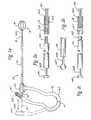
- FIG. 1 ais a plan view of a first embodiment of a rigid extractor.
- FIG. 1 bis a plan view of another embodiment of a rigid extractor.
- FIG. 1 cis a plan view of another embodiment of a rigid extractor.
- FIG. 1 dis a plan view of yet another embodiment of a rigid extractor.
- FIG. 2 ais a plan view of the proximal end of an inner cannula along with a sectional view of an extraction cannula according to one embodiment.
- FIG. 2 bis a plan view of an inner cannula according to the embodiment of FIG. 1 .
- FIG. 2 cis a plan view of an inner cannula and extraction cannula according to one embodiment.
- FIG. 2 dis a plan view of an inner cannula and extraction cannula according to one embodiment.
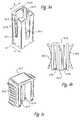
- FIG. 3 ais a perspective view of a portion of the handle according to FIG. 1 a.
- FIG. 3 bis a plan view of a handle cap according to FIG. 1 a.
- FIG. 3 cis a perspective view of the handle cap of FIG. 3 b.
- FIG. 3 dis a perspective view of a portion of the handle according to FIG. 1 b.
- FIGS. 4 a and 4 bare perspective and cross-sectional views of the rigid outer cannula according to FIGS. 1 a and 1 b.
- FIGS. 5-10are embodiments of loops for the wires forming a basket for the retrieval device of FIGS. 1 a and 1 b.
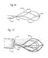
- FIGS. 11 and 12are grasper embodiments of the rigid extractor.
- FIG. 13is a three-prong grasper embodiment of the rigid extractor.
- FIG. 14is a retrieval loop embodiment of the rigid extractor.
- FIG. 15is a helical three-wire basket embodiment of the rigid extractor.
- FIG. 16is a helical tipless basket embodiment of the rigid extractor.
- FIG. 17is a multi-wire basket embodiment of the rigid extractor.
- FIG. 18is another multi-wire basket embodiment of the rigid extractor.
- FIG. 19is a three-loop grasper embodiment of the rigid extractor.
- FIGS. 20-24are alternate embodiments of a basket for the extractor.
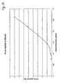
- FIG. 25is a graph of actuation force as a function of handle thickness.
- FIG. 26is a flowchart for a method of using the rigid extractor.
- a first embodimentis a rigid extractor useful in grasping and removing kidney stones from a patient.
- the kidney stoneswill typically have been reduced in size by a procedure in which laser energy, electro-hydraulic energy, or sound energy is applied to reduce the stones in size for easier removal.
- a first embodimentis depicted in FIG. 1 a .
- the rigid extractor 10comprises a rigid outer cannula 12 and an inner cannula 14 .
- the inner cannula 14is secured to a removable extraction device 18 , illustrated in FIG. 1 a as a basket 18 formed from at least one wire loop 181 .
- the extraction device 18is not removable.
- the extraction cannula 15is configured to be attached to an extraction cannula 15 of the same outer diameter as the inner cannula 14 .
- the extraction cannula 15is configured to be removably secured to the inner cannula 14 .
- the inner cannula 14 and the extraction cannula 15have mating threaded portions 143 , 153 which can be screwed together, thus securing the extraction device 18 to the inner cannula 14 .
- the removable extraction device 18may be any of a number of different engagement means, such as forceps, graspers, loops, or various basket varieties available to surgeons.
- the extractor 10also has a handle 16 for operating the extractor.
- the handle 16comprises a first end 161 attached to the inner cannula 14 , and a second end 162 , attached to the outer cannula 12 .
- the handlealso comprises a gripping portion with a flexible section 163 .
- the basket 18is tipless, in the sense that there is no distal “end” to the basket in which the wires are secured to each other by soldering, welding, brazing, adhering, or the like.
- the extractor 18is operated by applying hand pressure to the handle 16 , squeezing the handle 16 , deflecting the first end 161 to the right in FIGS. 1 a and 1 b , and causing the inner cannula 14 to translate to the right, and extending the extraction device 18 , here a basket.
- the handle 16is shown in solid line in the “squeezed” position, and in dotted line in the “relaxed” condition. It is understood that the basket is extended from the outer cannula 12 as shown when the operator or surgeon applies pressure and squeezes the handle 16 . When no pressure is applied to the handle 16 , it is in a relaxed state, and the basket is collapsed within the outer cannula 12 .
- the handle 16is not meant for insertion into the body of a patient, but remains outside the body during procedures for removing objects from a body.
- the handle 16preferably is made of nylon or other acceptable plastic.
- the handle 16 shown in FIGS. 1 a and 1 bhas a length of about 3.5 inches (up and down) and the gripping portion has an inner diameter of about 1.05 inches and an outer diameter of about 1.50 inches.
- the thickness of the handle 16in the direction of arrow A in FIGS. 1 a and 1 b , determines the force needed to deflect the handle 16 and extend the basket from the cannula.
- the thickness of the handle 16is 0.225 inches, but it may also be from about 0.20 inches to about 0.25 inches, and may range from about 0.15 inches to about 0.30 inches.
- the width of the handle 16 , perpendicular to the thickness direction shown,is preferably about 0.25 inches, but is not of particular importance, and may vary from about 0.125 inches to about 1 inch.
- the thickness of the handle 16is important because the thickness determines the force required to deflect the handle 16 and extend the basket. This force should be sufficient so that movement of the handle 16 , and thus the basket, or other retrieval assembly on the distal end of the inner cannula, is deliberate but not difficult. In the course of conducting many tests, it was determined that a force of about five pounds is particularly preferred, while a force from about one pound to about eight pounds could be conveniently used. A force of about five pounds is necessary to deflect the handle 16 if it is made from nylon 6, in a thickness of about 0.225 inches. When the handle 16 is made with a thickness of about 0.150 inches, a force of about 1 pound is sufficient to operate the extractor. A thickness of over about 0.25 inches requires even greater force. The preferred thickness of the handle 16 is therefore from about 0.20 to about 0.25 inches, preferably about 0.225 inches, and nylon 6 is a preferred material.
- the outer cannula 12is a desirably rigid hollow tube that does not deflect appreciably in use.
- the extractormay be used with a nephroscope, in which the surgeon inserts the rigid extractor and its outer cannula 12 into an appropriate channel in the nephroscope.
- the nephroscopeallows the surgeon to view the operating field as the surgeon maneuvers the nephroscope and the extractor to capture and remove objects within the body, such as kidney stones.
- the outer cannula 12is sufficiently rigid for the surgeon to deflect and maneuver the nephroscope by using the outer cannula 12 of the rigid extractor.
- the outer cannula 12is desirably made from a medically acceptable material such as stainless steel or stiff plastic material, preferably those with minimal coefficients of friction, such as reinforced plastic, stiff polyimide, PTFE, and other medically acceptable materials. 316 stainless steel is a preferred material.
- the outer cannula 12may vary in length from about 20 cm to about 60 cm. An intermediate length of about 38 cm works well with most patients and is preferred.
- the outer cannula 12preferably has a wall thickness of at least 0.010 inches, desirably 0.014 inches, and more preferably 0.015 inches. The greater the wall thickness, the more rigid will be the outer cannula 12 . This rigidity enables the surgeon to control the nephroscope and to maneuver the nephroscope into a desired position. The surgeon thus delivers the outer cannula 12 and the basket 18 to the desired location within the operating field.
- the outer cannula 12may preferably have an outer diameter from about 0.110 inches to about 0.200 inches, or from about 8.5 Fr to about 15.5 Fr.
- the inner diameter of the outer cannula 12depends on the dimension of the outer cannula 12 and sufficient wall thickness to maintain the desired rigidity.
- the inner diameter of the outer cannula 12may preferably range from about 0.080 inches to about 0.175 inches (from about 6 Fr. to about 13.5 Fr.). It is understood that wall thicknesses are preferably maintained at a minimum of 0.015 inches, but wall thicknesses slightly less than 0.015 inches may also be used.
- the outer cannula 12may be covered with a thin adherent plastic covering, in order to aid the physician in placing the extractor.
- the coveringis desirably a medical grade plastic material, such as Teflon® (PTFE) or other grade of plastic or fluoropolymer. These may include FEP, fluorinated ethylene propylene, PFA, perfluoroalkoxy polymer, and other medically-acceptable grades of thermoplastic or thermoset coatings.
- the coveringis desirably thin, preferably about 0.10 to about 0.4 mm thick (about 0.004 to about 0.015 inches thick).
- FIGS. 4 a and 4 bdepict an outer cannula 12 and a thin plastic covering 121 on the outer diameter of the cannula.
- the inner cannula 14is preferably a solid rod, also made from stainless steel, although a hollow rod or tubing may also be used.
- the outer diameter of the inner cannulamust fit within the inner diameter of the outer cannula 12 , with sufficient clearance for easy movement within the outer cannula 12 .
- the inner cannulais desirably at least about 0.065 inches in diameter (about 5 Fr). Other diameters may be used.
- the inner cannula 14 and the extraction cannula 15have mating threaded portions 143 , 153 which can be screwed together, thus securing the extraction device 18 to the inner cannula 14 .
- the extraction cannula 15 and the inner cannula 14may be removable secured together with a snap fit connection as shown in FIG. 2 c , or any other means known in the art.
- the snap fit connectionis made with a male portion 155 on the inner cannula 14 , and a female portion 157 on the extraction cannula 15 .
- the male and female portions of the threaded or snap fit connectionsmay be reversed.
- the extraction cannula 15preferably has substantially the same outer diameter as the inner cannula 14 .
- the extraction cannula 15may also have a short portion on its distal end hollowed out so that the wire loops and legs used to make the basket may fit into the distal end of the extraction cannula 15 .
- the wiresare then desirably crimped to the extraction cannula 15 , as shown in FIG. 2 a at location 142 . They may also be secured to the inner cannula with an adhesive 144 , such as a medically-acceptable grade of cyanoacrylate adhesive. Loctite 4011 works well and is preferred.
- the removable extraction device 18may be any of a number of different engagement means, such as forceps, graspers, loops, or various basket varieties available to surgeons.
- a rigid extractor outer cannula 12has an outer diameter of about 4.5 Fr, about 0.059 inches, and an inner diameter of about 0.0465 inches with a nominal wall thickness of about 0.0065 inches.
- the inner cannula 14 and extraction cannula 15have an outer diameter of about 0.0425 inches and an inner diameter of about 0.0315 inches.
- a plug about 3 or 4 inches longwas adhered to the proximal end of the inner cannula, near the point where it attaches to the handle 16 .
- the particular embodimentwas made of 316 stainless steel. Other materials suitable for the application may also be used. While this cannula is less rigid than one with walls 0.010 inches thick, it is much easier to control than a “flexible” cannula.
- FIG. 2 adepicts an inner cannula 14 with a restriction member in the form of a T-shaped fitting 141 on the proximal end of the inner cannula, for fitting into a matching slot 261 in the first end 161 of the handle 16 .
- the slot 261is illustrated in FIG. 3 a .
- FIG. 2 aalso depicts a cross section of an extraction cannula 15 , which has at least one wire 181 secured to the cannula by a crimp 142 at the distal end of the cannula.
- the wiresmay also be secured with adhesive 144 as shown.
- FIG. 2 bdepicts an alternative embodiment of the proximal end of the inner cannula wherein the T-shaped fitting restriction member is replaced by a cylindrical T-bar 149 .
- the restriction memberis preferably attached to the proximal portion of the inner cannula 14 with a narrow rod 268 of a diameter preferably about half the diameter of the inner cannula 14 .
- the proximal end of the inner cannulais designed to remain within the slot 261 so that when the handle 16 is actuated, the inner cannula may be pushed to extend the extraction device.
- FIG. 2 ddepicts an inner cannula 14 with a T-shaped fitting 141 on the proximal end of the inner cannula, for fitting into a matching slot in the first end 161 of the handle 16 .
- the inner cannula 14also has at least one wire 181 secured to the cannula by a crimp 142 at the distal end of the cannula.
- the wiresmay also be secured with adhesive 144 as shown.
- FIG. 3 ddepicts a close view of the first end 161 of the handle used to operate the rigid extractor of FIG. 1 b .
- the first end 161includes a hollow portion forming a slot as shown, to receive the T-shaped fitting 141 of the proximal end of the inner cannula.
- the first endmay have a thickness designated in the direction of arrow A, and may have a width as shown in the direction of arrow B.
- the slotmay extend a short distance into the first end of the handle, the distance being sufficient so that the inner cannula is not easily dislodged from the first end.
- FIG. 3 adepicts a perspective view of the first end 161 of the handle 16 used to operate the rigid extractor.
- the first end 161includes a hollow portion forming a slot 261 as shown, which opens towards the distal end to receive the restriction member, preferably the T-shaped fitting 141 , of the proximal end of the inner cannula.
- the first end 161may have a thickness designated in the direction of arrow A, and may have a width as shown in the direction of arrow B.
- the slotmay extend a short distance into the first end of the handle 16 , the distance being sufficient so that the inner cannula is not easily dislodged from the first end. A distance from about 0.25 inches to about 0.50 inches (about 6 to about 13 mm) is sufficient; about 0.375 inches (9-10 mm) is preferred.
- the T-shaped fitting 141 or alternative restriction membershould be sized such that it can fit through and be pulled out of the slot 261 .
- the T-shaped fittinghas the same height and width, or diameter, as the diameter of the inner cannula. This enables the user to easily pull the inner cannula 14 distally through the outer cannula 12 if need be should complications arise during a procedure.
- a cap 263is provided to secure the proximal end of the inner cannula within the cavity 260 of the first end of the handle 16 .
- the cap 263is illustrated in FIGS. 1 a , 3 b and 3 c .
- the fitting 141is pushed to the proximal end of the cavity and the cap 263 is pushed down and secured within the cavity 260 .
- the cap 263has finger grips 266 on either side, as well as a central slot 267 and a lip portion 272 .
- the finger grips 266are designed to enhance friction between the user's fingers and the cap 263 to make it easier to secure and remove the cap 263 within the cavity 260 .
- the two lip portions 272are aligned with the two mirror-image side slots 264 of the cavity illustrated in FIG. 3 a .
- the cap 263can then be pushed downwards until the lips 272 engage the center notch 273 of the side slot.
- the center notches 273are merely an intermediate stopping point, and are provided so that the cap 263 is not easily removed from the cavity 260 .
- the cap 263To secure the inner cannula 14 within the cavity 260 , the cap 263 must be pushed all the way down until the lips 272 engage the bottom notches 271 of the cavity's side slots 264 . Both the center notches 273 and the bottom notches 271 are slightly wider than the rest of the side slots 264 . As such, these notches will hold the cap 263 in place by prohibiting the lips 272 from moving into the more narrow portions of the side slots 264 without additional force being exerted on the cap 263 by the user. Once the cap 263 is pushed down and the lips 273 are engaged in the bottom notches 271 , the center slot of the cap 267 will be aligned with the slot of the first end 261 .
- the handle 16 , the outer cannula 12 , the cap 263 , the inner cannula, and the extraction cannula 15cooperate to extend the extraction device from the outer cannula 12 and retract the extraction device.
- the basket 18preferably is made so that it extends about 2.7 cm plus or minus 2 mm (about 1.05 inches plus or minus about 0.08 inches). Other extensions may be used.
- the basketwill extend to the extent that the inner cannula is moved by the surgeon applying force and translating the inner cannula inside the outer cannula 12 .
- the handle 16should be designed and made so that squeezing the handle 16 causes the first end 161 to deflect the desired amount by the time the first end contacts the second end 162 and no further translation of the inner cannula or the basket is possible.
- the width of the basketis about 1.8 cm, plus or minus about 2 mm (about 0.71 inches plus or minus about 0.08 inches). Other configurations may be used.
- the wires used to form the basketare preferably a superelastic shape-memory material, such as Nitinol, a Ni—Ti alloy. Other alloys, such as Cu—Zn—Al, or Cu—Al—Ni may also be used. Round wires are preferably used to form the basket, but triangular and flat wires may also be used. Wires having a diameter of from about 0.08 mm to about 0.15 mm (about 0.003 inches to about 0.006 inches) are preferred, because their use permits a very small diameter basket, and hence a small diameter cannula. It is also preferred that the wires and the small loops used to restrict movement of the wires be kink-free. This is achieved by using the shape-memory metals mentioned above, and heat treating them in the desired shape for a short period of time.
- Shape-memory or superelastic materialsare heat treated or annealed from a weak (martinsite) structure to a strong (austenite) structure.
- the alloysare weak and deformable in the martinsitic state, which is thus useful for forming the basket and the loops.
- After transformation to the strong or martensitic statethey exhibit a superelastic property so long as the material remains above a transformation temperature, at which temperature it will revert to the martensitic state.
- the transformation temperatureis desirably a low temperature, well below the temperature of a human body, and preferably below room temperature, about 20-25° C.
- the transformation temperature of the wires and the basketis thus selected to be below the operating temperature of the basket, thus keeping the basket in a superelastic state.
- the wiresadvantageously return to their original, unstressed shape when deforming stresses are removed.
- the superelastic wire alloyalso increasingly resists deformation as the stress load is increased.
- the basketsare formed by shaping the wires and loops into the desired shape at room temperature or below, preferably with one or more cold mandrels, and then annealing the properly-shaped basket at the proper annealing temperature for a time sufficient for the transformation to a superelastic state.
- a basketis formed from 0.15 mm diameter (about 0.006 inches) Ni—Ti Nitinol wire and is annealed at 800° F. (about 427° C.) for about 10 minutes. The time and temperature for annealing will vary with the alloy selected and with the diameter (thickness) of the wire.
- the basket itselfnot the annealing oven, must remain at the desired annealing temperature for the proper length of time for annealing to be complete. Proper annealing is very important for the wires and the loops to remain kink-free during deployment and operation of the basket. If kinks form for any reason, it may be difficult to deploy (expand) or retract the basket.
- the basketis desirably formed before the annealing operation, as discussed above, including all wires and loops. It is preferred for the small loops formed in the wires to be arranged so that the loops are on the inside of the basket, rather than the outside. Having small loops on the inside of the basket is advantageous in two ways. The loops are less likely to become kinked during basket deployment and maneuvers. And the basket and extractor are less likely to cause trauma to tissue that is contacted by the basket, i.e., the basket and the extractor are then atraumatic. Of course, the loops are not likely to cause trauma even if they are outside the basket, but they are preferred on the inside.
- FIGS. 1 c and 1 dfeature alternate embodiments of the rigid extractor. While the handle depicted in FIG. 1 a is preferred, other handles and configurations may be used.
- FIG. 1 cdepicts an embodiment of a rigid extractor 110 in which the outer cannula 112 is fixed to a handle 109 with a fitting 113 while the proximal end of the movable inner cannula 114 (shown in dotted line) is attached to a control button 111 .
- a tipless, atraumatic basket(not shown) is attached to the distal end of the inner cannula.
- FIG. 1 ddepicts an even simpler embodiment 120 of a tipless atraumatic basket 126 with a rigid outer cannula 125 .
- the basket 126is affixed to the inner cannula 147 by a crimp joint 148 .
- the inner cannula 147 and control button 122are used to deploy the basket 126 from the outer cannula 125 to encircle and remove stones or calculi from a body.
- FIGS. 5-10depict several embodiments of small loops that may be used to restrict movement of the wires, large loops, and legs that form the basket for the rigid extractor.
- a basketis formed from two large loops 181 , 182 , wherein large loop 181 is formed with an integral small loop 184 that encircles the other large loop 182 .
- the diameter of the small loopis desirably formed as small as possible without kinking.
- FIG. 6depicts a basket formed from two wires 181 , each formed with a small loop 183 that encircles the other small loop. In both FIGS. 5 and 6 , the small loops will coincide with the outer portion of the basket formed.
- a first wire 181is formed with a small loop 185 and a second wire 181 is formed with a small loop 186 , the small loops intertwined with the wires in such a manner that the loops are external to the basket, that is, the small loops depend outwardly from at least one of the large loops.
- the small loopsdesirably are formed inside the basket, and thus preferably depend inwardly from the large loops.
- FIG. 8Such a desirable configuration is depicted in FIG. 8 .
- a first wire 181is formed with a small loop 188 and a second wire 181 is also formed with a small loop 188 .
- the small loopsintertwine as shown, and will be contained within the basket, i.e., the small loops will depend inwardly from the large loops.
- FIGS. 5-8have used large-loop wires, in which a wire starts at the inner cannula with one end, forms part of a basket at its middle, and terminates at the inner cannula with the other end of the wire.
- Other embodiments of the basketmay use a single “leg,” in which a wire starts at the inner cannula at one end, and then terminates at the basket, as shown in FIGS. 9-10 .
- a large loop of wire 181is formed with a small loop 183
- a wire leg 182terminates with a small loop 191 , the small loops 183 , 191 intertwining and acting to restrict movement of both the wire loop 181 and the leg 182 .
- leg 182should be terminated back upon itself in a joint 193 , 194 that has no sharp edges or burrs. This will ensure that the basket and the extractor will remain atraumatic.
- the rigid extractor with tipless, atraumatic, shape-memory basketmay be used with a nephroscope, as mentioned above, or it may also be used directly, with a fluoroscope to aid the surgeon in manipulating the extractor to find, encircle, and remove a kidney stone or other object within a body.
- the methodis preferably used after lithotripsy, in which the kidney stones are reduced in size by the application of sound energy, laser energy, electro-hydraulic energy, or other outside source of energy to reduce the stones in size.
- a needleis inserted below the 12th rib of a patient.
- a wire guideis inserted into the region of interest, and the opening is dilated sequentially by a series of small but increasingly larger tubes.
- a final tube up to 26 Fr to 30 Frmay be used.
- an access sheathsuch as a PTFE access sheath, may be subsequently inserted and the dilation tube removed. The rigid extractor is then inserted through the access sheath.
- nephroscopy and a nephroscopemay be used instead of fluoroscopy.
- the rigid cannulais expected to find use in procedures for removing kidney stones from patients.
- the rigid extractormay also be used in other applications, such as the urinary, biliary, vascular or other systems.
- the details of the construction or composition of the various elements of the rigid extractor, the outer cannula 12 , the inner cannula, and the basket, not otherwise disclosedare not believed to be important to the achievement of the advantages of the present invention, so long as the elements possess the strength or rigidity or elasticity, as described above, as needed to perform as desired.
- the selection of such details of constructionare believed to be well within the ability of one having skill in the art, in view of the present disclosure.
- FIG. 11depicts an extractor 130 with a jaw-type retrieval device 133 for grasping an object within a body.
- a userextends the jaws from the rigid outer cannula 131 and actuates the jaws using inner cannula 14 , which is preferably removably secured to the extraction cannula 132 and control handle 16 .
- Shape-memory metalsmay be used so that the jaws are in a relaxed state when extended from the outer cannula and in a stressed state when they are in the cannula.
- FIG. 12depicts an embodiment of an extractor 140 with a scissors-type retrieval assembly 145 for cutting, as for a biopsy.
- the scissors-type retrieval assemblyis controlled by the inner cannula, which is preferably removably secured to the extraction cannula 148 and control handle 16 .
- the scissorsWhen the scissors are extended from the outer cannula 147 , they separate and may be used for cutting.
- the scissorsmay be equipped with a “mouse tooth” 146 for impaling an object within a body. Shape-memory metals may be used so that the scissors are in a relaxed state when extended from the outer cannula 147 and in a stressed state when they are in the cannula.
- each retrieval assembly or deviceis connected to an extraction cannula removably secured to the inner cannula 14 with mating threaded portions 143 , 153 , as depicted in FIG. 2 a .
- the extraction cannulamay be secured to the inner cannula 14 with a snap fit connection 155 , 157 as shown in FIG. 2 c , or any other means known in the art.
- FIG. 13depicts an embodiment of an extractor 135 of the three-prong variety.
- the three-prong grasper 135may be equipped with three inward-facing “mouse tooth” projections 136 for grasping calculi.
- the three-pronged grasper 135may be secured to an extraction cannula, which in turn is removably secured to the inner cannula 14 .
- a userextends the three-pronged grasper 135 from the rigid outer cannula 137 and actuates the grasper 135 using the inner cannula 14 and the control handle 16 .
- Shape-memory metalsmay be used so that the three-pronged grasper is in a relaxed state when extended from the outer cannula 137 and in a stressed state when they are in the cannula 137 .
- FIG. 14depicts an embodiment of an extractor 215 of the single-loop variety.
- the single-loop extractor 215may be equipped with a single knot or loop 216 at its distal end.
- the single-loop extractor 215may be secured to an extraction cannula, which in turn is removably secured to the inner cannula 14 .
- a userextends the single-loop extractor 215 from the rigid outer cannula 217 and actuates the extractor 215 using the inner cannula 14 and the control handle 16 .
- Shape-memory metalsmay be used so that the single-loop extractor is in a relaxed state when extended from the outer cannula 217 and in a stressed state when inside the cannula 217 .
- FIG. 15depicts an embodiment of a helical extractor 217 .
- the helical extractor 217may be equipped with a solder joint 218 at its tip.
- a braze joint or weld jointcan be used to join the wires 219 to form a distal end of the helical basket 217 .
- a solder jointjoins the three wires 219 , which are secured to the extraction cannula 220 .
- the extraction cannula 220is preferably removably secured to the inner cannula 14 .
- the three wires 219are made from a shape-memory metal so that the three wires 219 form the helical extractor or basket formation, shown in FIG.
- the helical extractor 217when in a relaxed state extended from the outer cannula 222 .
- the helical extractor 217is in a stressed state when it is inside the outer cannula 222 .
- a userextends the helical extractor 217 from the rigid outer cannula 217 and actuates the extractor 217 using the inner cannula 14 and the control handle 16 .
- FIG. 16depicts an embodiment of a helical tipless extractor 224 .
- the helical tipless extractor 224may be equipped with a knot or loop 218 at its distal end.
- four wire segments 225form the helical tipless basket, and the four wire segments 225 are secured to the extraction cannula 228 .
- the extraction cannula 228is preferably removably secured to the inner cannula 14 .
- the four wire segments 225are made from a shape-memory metal so that the wire segments 225 form the helical extractor or basket formation, shown in FIG. 16 , when in a relaxed state extended from the outer cannula 227 .
- the helical tipless extractor 224is in a stressed state when it is inside the outer cannula 227 .
- a userextends the helical tipless extractor 224 from the rigid outer cannula 227 and actuates the extractor 224 using the inner cannula 14 and the control handle 16 .
- FIGS. 17 and 18depict embodiments of multiple-wire baskets.
- FIG. 17depicts a multiple-wire basket 229 which is designed to improve stone-free rates.
- the multi-wire geometryprovides a tight weave designed to capture routine stones as well as small fragments left behind following a procedure such as an intracorporeal lithotripsy.
- this embodimentmay be used with an outer cannula 230 of a larger diameter and including additional openings 231 , 232 for providing a surgeon with light, or additional surgical tools.
- the multiple-wire basket 229 geometrymay be created as a twelve or sixteen wire basket. In this embodiment, the multiple wire segments which form the basket 229 are secured to the extraction cannula 233 .
- the extraction cannula 233is preferably removably secured to the inner cannula 14 .
- the wire segments which create the basket geometry 229are made from a shape-memory metal so that the wire segments form the basket formation, shown in FIG. 17 , when in a relaxed state while extended from the outer cannula 230 .
- the basket 229is in a stressed state when it is inside the outer cannula 230 .
- a userextends the basket 229 from the rigid outer cannula 230 and actuates the basket 229 using the inner cannula 14 and the control handle 161 .
- FIG. 18depicts a multiple-wire basket embodiment 234 with an umbrella design.
- the umbrella basket 234is made from wire segments of a shape-memory metal so that the wire segments form the umbrella basket when in a relaxed state while extended from the outer cannula 235 .
- the basket 234is in a stressed state when inside the outer cannula 235 .
- a userextends the basket 234 from the rigid outer cannula 235 and actuates the basket 234 using the inner cannula 14 and the control handle 161 .
- This embodimentis designed to minimize stone migration during intracorporeal lithotripsy by providing an exceptionally tight weave.
- the umbrella basket 234traps stone fragments in the weave, and the surgeon can then remove the basket 234 and outer cannula 235 along with the fragments.
- FIG. 19depicts a six wire segment, three loop extractor 236 .
- the three-loop grasper 236may be used to engage, reposition, release, or extract stones or calculi in the kidney or the ureter.
- the three-loop grasper 236may be secured to an extraction cannula, which in turn is removably secured to the inner cannula 14 .
- a userextends the three-loop grasper 236 from the rigid outer cannula 238 and actuates the grasper 236 using the inner cannula 14 and the control handle 161 .
- Shape-memory metalsmay be used so that the three-loop grasper is in a relaxed state when extended from the outer cannula 238 and in a stressed state when they are in the cannula 238 .
- the thickness of the handledetermines the force that the surgeon uses to extend the basket from the sheath. If the handle 16 , the inner cannula 14 , the outer cannula 12 , and the basket 18 are relatively free of friction, then the potential energy stored in the “squeezed” handle 16 is available for grasping a stone or other calculus. This force used to squeeze the handle 16 is stored as potential energy in the deformation of the handle 16 , much as energy is stored in a compressed spring.
- That energy or forceis applied to the stone or calculus when the surgeon releases the handle 16 and the potential energy is used to trap or “squeeze” the stone or calculus, or to operate another retrieval assembly at the distal end of the inner cannula 14 .
- the force desiredis typically that force which is sufficient to trap and hold, but not sufficient to crush or cut, the stone or calculus.
- FIGS. 1 a and 1 bA series of experiments was conducted with a rigid extractor similar to the embodiment of FIGS. 1 a and 1 b to determine the force available at the basket with a series of plastic handles similar to those in FIGS. 1 a and 1 b .
- the material usedwas Nylon 6, and the thickness of the handle 16 was varied from about 0.075 inches to about 0.28 inches.
- the basketwas hooked to a mechanical load cell to measure the force, and the result of the experiments is shown in FIG. 25 .
- the datasuggest that the force correlates almost linearly with the handle 16 thickness, particularly if the handle 16 thickness is from about 0.15 to about 0.27 inches thick. When the thickness is less than 0.15 inches, the force drops below one or two pounds, and the effects of even small amounts of friction may govern. The force is less predictable in that range.
- the handle 16may require a force in excess of eight or ten pounds to extend the basket, making the handle 16 and the extractor difficult to operate. It is also clear, that besides varying the handle 16 thickness, the material may be varied, with materials of a lower flexural modulus of elasticity requiring less force while material having a higher flexural modulus will require more force.
- the shape of the handle 16 cross-sectionmay also be varied, such as by adding ribs or other reinforcing members for a greater force, or by making cuts for a lesser force.
- the extractorprovides a way to control the force used to extend the basket, and thus also control the force applied to the stone or calculus to be removed. In embodiments using a scissors or jaw-type or grasper-type assembly, the design and selection of the handle 16 allows a user to tailor the cutting or grasping force applied to the object to be removed from a body.
- FIG. 26depicts a method used to remove stones or calculi from a body using the rigid extractor with a tipless, atraumatic basket and a rigid outer cannula.
- the methodcomprises a step 261 of forming a passage in order to insert the extractor.
- the next step 262is to provide a view of the operating field for the surgeon. As discussed above, the view is preferably provided by a fluoroscope or a nephroscope.
- the physicianthen inserts the extractor 263 near the object to be removed, and then extends the basket from the rigid cannula 264 . Because the cannula is rigid, it may be moved as desired, even deflecting a nephroscope if one is being used. After the basket is extended, it is necessary to maneuver the basket by using the handle 16 to capture the object 265 . The basket is closed by relaxing the grip on the handle 166 . Then the object is removed from the body 267 .
- the basket used for retrievalneed not be limited to the tipless basket formed by looping the wires with small loops, as described above.
- FIGS. 20-24depict alternate embodiments of baskets useful with the rigid cannula.
- the wires 200may be secured by a knot or knots 201 in the wires themselves.
- a separate wire or filament 205may be used to secure the wires 203 to form a distal end of the basket.
- Wiresuch as Nitinol wire or other medically acceptable wire, such as stainless steel, may be used. Filaments, such as those made from suture material, or other medically-acceptable material, may also be used.
- FIG. 22Other techniques may also be used, as shown in FIG. 22 , to join wires 207 by using solder joints 209 , braze joints, or weld joints, thus joining the wires to form a distal end of the basket.
- FIG. 23it is even possible to drill holes 212 and use a rivet 213 to join the distal ends of wires 211 , to form a distal end of the basket.
- the rivet embodimentis better accomplished with flat wire than with round wire.
- FIG. 24may use a small elastomeric or plastic fastener or ball 223 to join the distal ends of wires 221 to form a distal end of a basket useful in the rigid extractor embodiments of the present invention.
Landscapes
- Health & Medical Sciences (AREA)
- Surgery (AREA)
- Life Sciences & Earth Sciences (AREA)
- Medical Informatics (AREA)
- Animal Behavior & Ethology (AREA)
- Engineering & Computer Science (AREA)
- Biomedical Technology (AREA)
- Heart & Thoracic Surgery (AREA)
- Veterinary Medicine (AREA)
- Molecular Biology (AREA)
- Nuclear Medicine, Radiotherapy & Molecular Imaging (AREA)
- General Health & Medical Sciences (AREA)
- Public Health (AREA)
- Ophthalmology & Optometry (AREA)
- Orthopedic Medicine & Surgery (AREA)
- Vascular Medicine (AREA)
- Surgical Instruments (AREA)
- Endoscopes (AREA)
Abstract
Description
Claims (16)
Priority Applications (2)
| Application Number | Priority Date | Filing Date | Title |
|---|---|---|---|
| US12/177,446US8043303B2 (en) | 2002-10-04 | 2008-07-22 | Handle for interchangeable medical device |
| EP09166143AEP2147643B1 (en) | 2008-07-22 | 2009-07-22 | Extractor with handle |
Applications Claiming Priority (3)
| Application Number | Priority Date | Filing Date | Title |
|---|---|---|---|
| US41603502P | 2002-10-04 | 2002-10-04 | |
| US10/679,007US20040122445A1 (en) | 2002-10-04 | 2003-10-03 | Rigid extractor |
| US12/177,446US8043303B2 (en) | 2002-10-04 | 2008-07-22 | Handle for interchangeable medical device |
Related Parent Applications (1)
| Application Number | Title | Priority Date | Filing Date |
|---|---|---|---|
| US10/679,007Continuation-In-PartUS20040122445A1 (en) | 2002-10-04 | 2003-10-03 | Rigid extractor |
Publications (2)
| Publication Number | Publication Date |
|---|---|
| US20090030427A1 US20090030427A1 (en) | 2009-01-29 |
| US8043303B2true US8043303B2 (en) | 2011-10-25 |
Family
ID=41211900
Family Applications (1)
| Application Number | Title | Priority Date | Filing Date |
|---|---|---|---|
| US12/177,446Expired - LifetimeUS8043303B2 (en) | 2002-10-04 | 2008-07-22 | Handle for interchangeable medical device |
Country Status (2)
| Country | Link |
|---|---|
| US (1) | US8043303B2 (en) |
| EP (1) | EP2147643B1 (en) |
Cited By (16)
| Publication number | Priority date | Publication date | Assignee | Title |
|---|---|---|---|---|
| US20090198249A1 (en)* | 2004-05-25 | 2009-08-06 | Scimed Life Systems, Inc. | Medical retrieval devices |
| US20120310222A1 (en)* | 2010-11-01 | 2012-12-06 | Olympus Medical Systems Corp. | Treatment apparatus |
| US8845621B2 (en) | 2010-10-19 | 2014-09-30 | Distal Access, Llc | Apparatus for rotating medical devices, systems including the apparatus, and associated methods |
| US9107691B2 (en)* | 2010-10-19 | 2015-08-18 | Distal Access, Llc | Apparatus for rotating medical devices, systems including the apparatus, and associated methods |
| US20150374989A1 (en)* | 2013-03-13 | 2015-12-31 | Steve HAZARD | Magnet installation systems and methods for use with cochlear implants |
| US20160278797A1 (en)* | 2015-03-24 | 2016-09-29 | Boston Scientific Scimed, Inc. | Retrieval devices and related methods of use |
| US10786269B1 (en)* | 2012-04-04 | 2020-09-29 | Zamir Brelvi | Disposable snare and retrieval device and associated method |
| US11000307B2 (en) | 2010-10-19 | 2021-05-11 | Minerva Surgical Inc. | Apparatus for rotating medical devices, systems including the apparatus, and associated methods |
| US11090072B2 (en) | 2018-03-12 | 2021-08-17 | Boston Scientific Limited | Medical devices and related methods |
| US11103270B2 (en) | 2013-11-26 | 2021-08-31 | Cilag Gmbh International | Handpiece and blade configurations for ultrasonic surgical instrument |
| US11382650B2 (en)* | 2015-10-30 | 2022-07-12 | Auris Health, Inc. | Object capture with a basket |
| US11439419B2 (en) | 2019-12-31 | 2022-09-13 | Auris Health, Inc. | Advanced basket drive mode |
| US11446050B2 (en) | 2014-04-28 | 2022-09-20 | Minerva Surgical, Inc. | Tissue resectors with cutting wires, hand operated tissue resecting systems and associated methods |
| US11534249B2 (en) | 2015-10-30 | 2022-12-27 | Auris Health, Inc. | Process for percutaneous operations |
| US11571229B2 (en) | 2015-10-30 | 2023-02-07 | Auris Health, Inc. | Basket apparatus |
| US11896330B2 (en) | 2019-08-15 | 2024-02-13 | Auris Health, Inc. | Robotic medical system having multiple medical instruments |
Families Citing this family (30)
| Publication number | Priority date | Publication date | Assignee | Title |
|---|---|---|---|---|
| EP2528517B1 (en) | 2010-01-27 | 2018-04-18 | Merit Medical Systems, Inc. | Shapeable retrieval device |
| US9428254B1 (en) | 2010-09-24 | 2016-08-30 | Katalyst Surgical, Llc | Microsurgical handle and instrument |
| EP2661233A4 (en) | 2011-01-04 | 2014-09-03 | Merit Medical Systems Inc | Multiple loop snare |
| KR101298690B1 (en)* | 2011-01-25 | 2013-08-21 | 신경민 | Medical Snare |
| US9039713B2 (en)* | 2011-05-13 | 2015-05-26 | Merit Medical Systems, Inc. | Releasably attached snare loop retrieval device and method of using the same |
| CN102178569B (en)* | 2011-06-08 | 2013-04-24 | 威海维心医疗设备有限公司 | Controlled release vena cava filter and processing method thereof |
| US8821444B2 (en) | 2011-10-03 | 2014-09-02 | Katalyst Surgical, Llc | Multi-utility surgical instrument |
| US8919832B1 (en) | 2011-12-12 | 2014-12-30 | Graham Lynch | Child safety door latch |
| US9138346B2 (en) | 2012-01-26 | 2015-09-22 | Katalyst Surgical, Llc | Surgical instrument sleeve |
| US9629645B2 (en) | 2012-10-30 | 2017-04-25 | Katalyst Surgical, Llc | Atraumatic microsurgical forceps |
| US9226762B2 (en) | 2012-11-07 | 2016-01-05 | Katalyst Surgical, Llc | Atraumatic microsurgical forceps |
| US20140142603A1 (en)* | 2012-11-19 | 2014-05-22 | Katalyst Surgical, Llc | Microsurgical instrument handle |
| WO2014091523A1 (en)* | 2012-12-13 | 2014-06-19 | 株式会社シャルマン | Medical instrument |
| US9204995B2 (en) | 2013-03-12 | 2015-12-08 | Katalyst Surgical, Llc | Membrane removing forceps |
| US11484734B2 (en) | 2013-09-04 | 2022-11-01 | Octo Safety Devices, Llc | Facemask with filter insert for protection against airborne pathogens |
| WO2015134846A1 (en)* | 2014-03-07 | 2015-09-11 | The University Of Akron | Surgical apparatus with force sensor for extraction of substances within the body |
| US10022267B2 (en) | 2014-04-21 | 2018-07-17 | Katalyst Surgical, Llc | Method of manufacturing a microsurgical instrument tip |
| DE202014006636U1 (en)* | 2014-08-14 | 2014-10-24 | Bacher Medizintechnik GmbH | Tubular shaft instrument with a tubular shaft and a flushing connection |
| US9775943B2 (en) | 2014-10-10 | 2017-10-03 | Katalyst Surgical, Llc | Cannula ingress system |
| EP3009085A1 (en)* | 2014-10-14 | 2016-04-20 | Coloplast A/S | Extraction device for removing foreign body from a patient |
| EP3297548B1 (en)* | 2015-06-25 | 2020-05-06 | Gyrus Acmi Inc., D.B.A. Olympus Surgical Technologies America | Retraction force sensing basket |
| US11160935B2 (en) | 2016-06-16 | 2021-11-02 | Katalyst Surgical, Llc | Reusable instrument handle with single-use tip |
| US10695043B2 (en) | 2017-02-21 | 2020-06-30 | Katalyst Surgical, Llc | Surgical instrument subcomponent integration by additive manufacturing |
| EP3684275A1 (en)* | 2017-09-20 | 2020-07-29 | Boston Scientific Scimed, Inc. | Force gauge and method of use |
| US11554276B2 (en)* | 2018-04-11 | 2023-01-17 | Octo Safety Devices, Llc | Facemask with facial seal and seal test device |
| US10849640B2 (en) | 2018-05-23 | 2020-12-01 | Katalyst Surgical, Llc | Membrane aggregating forceps |
| US20190380725A1 (en)* | 2018-06-14 | 2019-12-19 | Cook Medical Technologies Llc | Percutaneous extractor with laser assembly |
| WO2021101824A1 (en)* | 2019-11-22 | 2021-05-27 | Boston Scientific Scimed, Inc. | Device for tissue removal |
| US20210212708A1 (en)* | 2020-01-13 | 2021-07-15 | Cook Medical Technologies Llc | Extractor cannula securement and processing |
| CN112472205B (en)* | 2020-11-25 | 2022-02-11 | 西安交通大学医学院第一附属医院 | Percutaneous transhepatic sinus lithotomy device based on hepatobiliary surgery |
Citations (71)
| Publication number | Priority date | Publication date | Assignee | Title |
|---|---|---|---|---|
| US2137710A (en) | 1937-12-13 | 1938-11-22 | Alfred W Anderson | Forceps |
| DE2428329A1 (en) | 1973-06-13 | 1975-01-23 | Atomic Energy Commission | STACKING DEVICE FOR CYLINDRICAL PELLETS |
| DE2428319A1 (en) | 1974-06-12 | 1976-01-02 | Harry H Leveen | Gallstone extracting and locating device - has wire spiral at end of rod expanded and passed around stone |
| US4393872A (en) | 1980-05-27 | 1983-07-19 | Eder Instrument Co., Inc. | Aspirating surgical forceps |
| US4763668A (en) | 1985-10-28 | 1988-08-16 | Mill Rose Laboratories | Partible forceps instrument for endoscopy |
| US4872456A (en) | 1987-11-12 | 1989-10-10 | Hasson Harrith M | Template incision device |
| US4968678A (en) | 1988-02-19 | 1990-11-06 | Eli Lilly And Company | Tetrazole excitatory amino acid receptor antagonists |
| US5057114A (en) | 1990-09-18 | 1991-10-15 | Cook Incorporated | Medical retrieval basket |
| US5064428A (en) | 1990-09-18 | 1991-11-12 | Cook Incorporated | Medical retrieval basket |
| US5197968A (en) | 1991-08-14 | 1993-03-30 | Mectra Labs, Inc. | Disposable tissue retrieval assembly |
| US5222973A (en) | 1992-03-09 | 1993-06-29 | Sharpe Endosurgical Corporation | Endoscopic grasping tool surgical instrument |
| US5254088A (en) | 1990-02-02 | 1993-10-19 | Ep Technologies, Inc. | Catheter steering mechanism |
| US5290294A (en) | 1990-04-17 | 1994-03-01 | Brian Cox | Method and apparatus for removal of a foreign body cavity |
| US5308358A (en) | 1992-08-25 | 1994-05-03 | Bond Albert L | Rigid-shaft surgical instruments that can be disassembled for improved cleaning |
| US5308357A (en) | 1992-08-21 | 1994-05-03 | Microsurge, Inc. | Handle mechanism for manual instruments |
| US5318040A (en) | 1992-08-27 | 1994-06-07 | Kensey Nash Corporation | Instruments and methods for performing medical procedures via small percutaneous incisions or punctures without using a trocar |
| US5318589A (en) | 1992-04-15 | 1994-06-07 | Microsurge, Inc. | Surgical instrument for endoscopic surgery |
| US5330482A (en) | 1991-06-17 | 1994-07-19 | Wilson-Cook Medical Inc. | Endoscopic extraction devices, wire basket stone extractors, stent retrievers, snares and method of constructing the same |
| US5358508A (en)* | 1993-09-15 | 1994-10-25 | Eric Cobb | Laparoscopic device |
| US5376094A (en) | 1993-08-19 | 1994-12-27 | Boston Scientific Corporation | Improved actuating handle with pulley system for providing mechanical advantage to a surgical working element |
| EP0446020B1 (en) | 1990-03-05 | 1995-01-25 | C.R. Bard, Inc. | Surgical gripping instrument |
| US5387219A (en) | 1992-09-23 | 1995-02-07 | Target Therapeutics | Medical retrieval snare with coil wrapped loop |
| WO1995009566A1 (en) | 1993-09-29 | 1995-04-13 | Hingeless Tool Company ('hit') | Hingeless tool useful in surgery |
| EP0512729B1 (en) | 1991-05-03 | 1995-07-26 | VANCE PRODUCTS INCORPORATED d/b/a COOK UROLOGICAL INCORPORATED | Surgical instrument and its manufacturing method |
| WO1996004875A1 (en) | 1994-08-08 | 1996-02-22 | Inbae Yoon | Multifunctional devices having loop configured portions and collection systems for endoscopic surgical procedures and methods therefor |
| WO1996005773A1 (en) | 1994-08-23 | 1996-02-29 | Heartport, Inc. | Endoscopic retraction system and method |
| US5496330A (en) | 1993-02-19 | 1996-03-05 | Boston Scientific Corporation | Surgical extractor with closely angularly spaced individual filaments |
| EP0538984B1 (en) | 1991-07-29 | 1997-03-05 | Linvatec Corporation | Surgical forceps |
| WO1997017014A1 (en) | 1995-11-10 | 1997-05-15 | Nyfotek As | Surgical instrument |
| US5643282A (en) | 1994-08-22 | 1997-07-01 | Kieturakis; Maciej J. | Surgical instrument and method for removing tissue from an endoscopic workspace |
| WO1997038632A1 (en) | 1996-04-17 | 1997-10-23 | Teleflex, Incorporated | Surgical grasper devices |
| WO1997042884A2 (en) | 1996-05-10 | 1997-11-20 | Andrew Michael Wild | Surgical instrument assembly for use in endoscopic surgery |
| US5788710A (en) | 1996-04-30 | 1998-08-04 | Boston Scientific Corporation | Calculus removal |
| EP0679071B1 (en) | 1992-09-10 | 1999-03-24 | MARKHAM, Harold | Grasping forceps |
| US5906622A (en) | 1997-04-29 | 1999-05-25 | Lippitt; Robert G. | Positively expanded and retracted medical extractor |
| US5989266A (en)* | 1997-02-24 | 1999-11-23 | Foster; Thomas L. | Medical device including basket |
| US6071281A (en) | 1998-05-05 | 2000-06-06 | Ep Technologies, Inc. | Surgical method and apparatus for positioning a diagnostic or therapeutic element within the body and remote power control unit for use with same |
| US6099534A (en) | 1997-10-01 | 2000-08-08 | Scimed Life Systems, Inc. | Releasable basket |
| WO2000071036A2 (en) | 1999-05-25 | 2000-11-30 | Scimed Life Systems, Inc. | Releasable basket and method of making thereof |
| US6159220A (en) | 1999-03-11 | 2000-12-12 | Scimed Life Systems, Inc. | Medical retrieval device |
| US6162209A (en) | 1998-11-17 | 2000-12-19 | Scimed Life Systems, Inc. | Multi-function surgical instrument tool actuator assembly |
| US6168603B1 (en) | 1995-02-02 | 2001-01-02 | Boston Scientific Corporation | Surgical extractor |
| US6174318B1 (en) | 1998-04-23 | 2001-01-16 | Scimed Life Systems, Inc. | Basket with one or more moveable legs |
| US6183482B1 (en) | 1997-10-01 | 2001-02-06 | Scimed Life Systems, Inc. | Medical retrieval basket with legs shaped to enhance capture and reduce trauma |
| US6203552B1 (en) | 1998-03-20 | 2001-03-20 | Cook Urological Incorporated | Minimally invasive medical retrieval device |
| US6217589B1 (en) | 1999-10-27 | 2001-04-17 | Scimed Life Systems, Inc. | Retrieval device made of precursor alloy cable and method of manufacturing |
| US6224612B1 (en) | 1998-04-23 | 2001-05-01 | Scimed Life Systems, Inc. | Atraumatic medical retrieval device |
| US6258101B1 (en) | 2000-03-24 | 2001-07-10 | Lacey Manufacturing Company, Inc. | Instrument for deploying surgical devices |
| US6264664B1 (en) | 2000-03-10 | 2001-07-24 | General Science And Technology Corp. | Surgical basket devices |
| WO2001080748A2 (en) | 2000-04-26 | 2001-11-01 | Scimed Life Systems, Inc. | Hybrid stone retrieval device |
| US6342062B1 (en) | 1998-09-24 | 2002-01-29 | Scimed Life Systems, Inc. | Retrieval devices for vena cava filter |
| US6348056B1 (en) | 1999-08-06 | 2002-02-19 | Scimed Life Systems, Inc. | Medical retrieval device with releasable retrieval basket |
| US6368328B1 (en) | 1999-09-16 | 2002-04-09 | Scimed Life Systems, Inc. | Laser-resistant medical retrieval device |
| US6368338B1 (en) | 1999-03-05 | 2002-04-09 | Board Of Regents, The University Of Texas | Occlusion method and apparatus |
| US6464710B1 (en) | 1995-03-06 | 2002-10-15 | Cook Urological Incorporated | Releasable, surgical clamp |
| DE10125149A1 (en) | 2001-05-22 | 2002-12-12 | Bowa Electronic Gmbh | Medical pincers having improved handling mechanism with finger grips that move in and out along the line of the pincer shaft, obviating the need for a pivoting movement and improving ease of use and ergonomics |
| US6500182B2 (en) | 1998-03-27 | 2002-12-31 | Cook Urological, Incorporated | Minimally-invasive medical retrieval device |
| US20030023258A1 (en) | 2001-07-25 | 2003-01-30 | Dumontelle Jeffrey P. | Actuating handle for a surgical instrument |
| US6544227B2 (en) | 2001-02-28 | 2003-04-08 | Scimed Life Systems, Inc. | Immobilizing objects in the body |
| US20030109874A1 (en) | 2001-12-07 | 2003-06-12 | Dennis William G. | Surgical snare with steering tether and method of using same |
| US20030109889A1 (en) | 2001-12-12 | 2003-06-12 | Steve Mercereau | Articulating stone basket |
| US6602262B2 (en) | 2000-06-02 | 2003-08-05 | Scimed Life Systems, Inc. | Medical device having linear to rotation control |
| EP1348381A2 (en) | 1994-02-14 | 2003-10-01 | Heartport, Inc. | Endoscopic microsurgical instruments and methods |
| US6676668B2 (en) | 2001-12-12 | 2004-01-13 | C.R. Baed | Articulating stone basket |
| US6692484B1 (en) | 1999-07-17 | 2004-02-17 | Wilson-Cook Medical Incorporated | Devices for extracting biliary or urinary stones |
| US6720402B2 (en) | 1998-02-23 | 2004-04-13 | Mnemoscience Gmbh | Shape memory polymers |
| US20040122445A1 (en) | 2002-10-04 | 2004-06-24 | Vance Products, Inc. | Rigid extractor |
| US6893450B2 (en) | 1999-03-26 | 2005-05-17 | Cook Urological Incorporated | Minimally-invasive medical retrieval device |
| US20050192592A1 (en) | 2004-02-27 | 2005-09-01 | Cook Urological Incorporated | Self-tensioning handle for endoscopic device |
| US7041108B2 (en) | 2002-05-28 | 2006-05-09 | Lippitt Extractor Company, Llc | Grasper mechanism with biased fixed flexure elements |
| US7241299B2 (en) | 2002-09-17 | 2007-07-10 | Porges | Surgical extractor for extracting foreign bodies through natural or surgical passages |
Family Cites Families (1)
| Publication number | Priority date | Publication date | Assignee | Title |
|---|---|---|---|---|
| US6869150B2 (en)* | 2002-07-19 | 2005-03-22 | Zygmunt James Ptasinski | Tire step |
- 2008
- 2008-07-22USUS12/177,446patent/US8043303B2/ennot_activeExpired - Lifetime
- 2009
- 2009-07-22EPEP09166143Apatent/EP2147643B1/enactiveActive
Patent Citations (87)
| Publication number | Priority date | Publication date | Assignee | Title |
|---|---|---|---|---|
| US2137710A (en) | 1937-12-13 | 1938-11-22 | Alfred W Anderson | Forceps |
| DE2428329A1 (en) | 1973-06-13 | 1975-01-23 | Atomic Energy Commission | STACKING DEVICE FOR CYLINDRICAL PELLETS |
| DE2428319A1 (en) | 1974-06-12 | 1976-01-02 | Harry H Leveen | Gallstone extracting and locating device - has wire spiral at end of rod expanded and passed around stone |
| US4393872A (en) | 1980-05-27 | 1983-07-19 | Eder Instrument Co., Inc. | Aspirating surgical forceps |
| US4763668A (en) | 1985-10-28 | 1988-08-16 | Mill Rose Laboratories | Partible forceps instrument for endoscopy |
| US4872456A (en) | 1987-11-12 | 1989-10-10 | Hasson Harrith M | Template incision device |
| US4968678A (en) | 1988-02-19 | 1990-11-06 | Eli Lilly And Company | Tetrazole excitatory amino acid receptor antagonists |
| US5556376A (en)* | 1988-07-22 | 1996-09-17 | Yoon; Inbae | Multifunctional devices having loop configured portions and collection systems for endoscopic surgical procedures and methods thereof |
| US5254088A (en) | 1990-02-02 | 1993-10-19 | Ep Technologies, Inc. | Catheter steering mechanism |
| EP0446020B1 (en) | 1990-03-05 | 1995-01-25 | C.R. Bard, Inc. | Surgical gripping instrument |
| US5290294A (en) | 1990-04-17 | 1994-03-01 | Brian Cox | Method and apparatus for removal of a foreign body cavity |
| US5064428A (en) | 1990-09-18 | 1991-11-12 | Cook Incorporated | Medical retrieval basket |
| US5057114A (en) | 1990-09-18 | 1991-10-15 | Cook Incorporated | Medical retrieval basket |
| EP0512729B1 (en) | 1991-05-03 | 1995-07-26 | VANCE PRODUCTS INCORPORATED d/b/a COOK UROLOGICAL INCORPORATED | Surgical instrument and its manufacturing method |
| US5330482A (en) | 1991-06-17 | 1994-07-19 | Wilson-Cook Medical Inc. | Endoscopic extraction devices, wire basket stone extractors, stent retrievers, snares and method of constructing the same |
| EP0538984B1 (en) | 1991-07-29 | 1997-03-05 | Linvatec Corporation | Surgical forceps |
| US5197968A (en) | 1991-08-14 | 1993-03-30 | Mectra Labs, Inc. | Disposable tissue retrieval assembly |
| US5222973A (en) | 1992-03-09 | 1993-06-29 | Sharpe Endosurgical Corporation | Endoscopic grasping tool surgical instrument |
| US5318589A (en) | 1992-04-15 | 1994-06-07 | Microsurge, Inc. | Surgical instrument for endoscopic surgery |
| US5308357A (en) | 1992-08-21 | 1994-05-03 | Microsurge, Inc. | Handle mechanism for manual instruments |
| US5308358A (en) | 1992-08-25 | 1994-05-03 | Bond Albert L | Rigid-shaft surgical instruments that can be disassembled for improved cleaning |
| US5318040A (en) | 1992-08-27 | 1994-06-07 | Kensey Nash Corporation | Instruments and methods for performing medical procedures via small percutaneous incisions or punctures without using a trocar |
| EP0679071B1 (en) | 1992-09-10 | 1999-03-24 | MARKHAM, Harold | Grasping forceps |
| US5387219A (en) | 1992-09-23 | 1995-02-07 | Target Therapeutics | Medical retrieval snare with coil wrapped loop |
| US5496330A (en) | 1993-02-19 | 1996-03-05 | Boston Scientific Corporation | Surgical extractor with closely angularly spaced individual filaments |
| US5376094A (en) | 1993-08-19 | 1994-12-27 | Boston Scientific Corporation | Improved actuating handle with pulley system for providing mechanical advantage to a surgical working element |
| US5358508A (en)* | 1993-09-15 | 1994-10-25 | Eric Cobb | Laparoscopic device |
| WO1995009566A1 (en) | 1993-09-29 | 1995-04-13 | Hingeless Tool Company ('hit') | Hingeless tool useful in surgery |
| EP1348381A2 (en) | 1994-02-14 | 2003-10-01 | Heartport, Inc. | Endoscopic microsurgical instruments and methods |
| WO1996004875A1 (en) | 1994-08-08 | 1996-02-22 | Inbae Yoon | Multifunctional devices having loop configured portions and collection systems for endoscopic surgical procedures and methods therefor |
| US5643282A (en) | 1994-08-22 | 1997-07-01 | Kieturakis; Maciej J. | Surgical instrument and method for removing tissue from an endoscopic workspace |
| WO1996005773A1 (en) | 1994-08-23 | 1996-02-29 | Heartport, Inc. | Endoscopic retraction system and method |
| US6168603B1 (en) | 1995-02-02 | 2001-01-02 | Boston Scientific Corporation | Surgical extractor |
| US6350266B1 (en) | 1995-02-02 | 2002-02-26 | Scimed Life Systems, Inc. | Hybrid stone retrieval device |
| US6383196B1 (en) | 1995-02-02 | 2002-05-07 | Scimed Life Systems, Inc. | Surgical extractor |
| US6464710B1 (en) | 1995-03-06 | 2002-10-15 | Cook Urological Incorporated | Releasable, surgical clamp |
| WO1997017014A1 (en) | 1995-11-10 | 1997-05-15 | Nyfotek As | Surgical instrument |
| WO1997038632A1 (en) | 1996-04-17 | 1997-10-23 | Teleflex, Incorporated | Surgical grasper devices |
| US5788710A (en) | 1996-04-30 | 1998-08-04 | Boston Scientific Corporation | Calculus removal |
| WO1997042884A2 (en) | 1996-05-10 | 1997-11-20 | Andrew Michael Wild | Surgical instrument assembly for use in endoscopic surgery |
| US5989266A (en)* | 1997-02-24 | 1999-11-23 | Foster; Thomas L. | Medical device including basket |
| US5906622A (en) | 1997-04-29 | 1999-05-25 | Lippitt; Robert G. | Positively expanded and retracted medical extractor |
| US6520968B2 (en) | 1997-10-01 | 2003-02-18 | Scimed Life Systems | Releasable basket |
| US6280451B1 (en) | 1997-10-01 | 2001-08-28 | Scimed Life Systems, Inc. | Releasable basket |
| US6183482B1 (en) | 1997-10-01 | 2001-02-06 | Scimed Life Systems, Inc. | Medical retrieval basket with legs shaped to enhance capture and reduce trauma |
| US6491698B1 (en) | 1997-10-01 | 2002-12-10 | Scimed Life Systems, Inc. | Medical retrieval basket with legs shaped to enhance capture and reduce trauma |
| US6099534A (en) | 1997-10-01 | 2000-08-08 | Scimed Life Systems, Inc. | Releasable basket |
| US6720402B2 (en) | 1998-02-23 | 2004-04-13 | Mnemoscience Gmbh | Shape memory polymers |
| US6203552B1 (en) | 1998-03-20 | 2001-03-20 | Cook Urological Incorporated | Minimally invasive medical retrieval device |
| US6500182B2 (en) | 1998-03-27 | 2002-12-31 | Cook Urological, Incorporated | Minimally-invasive medical retrieval device |
| US6174318B1 (en) | 1998-04-23 | 2001-01-16 | Scimed Life Systems, Inc. | Basket with one or more moveable legs |
| US6626915B2 (en) | 1998-04-23 | 2003-09-30 | Scimed Life Systems, Inc. | Medical retrieval device with loop basket |
| US6527781B2 (en) | 1998-04-23 | 2003-03-04 | Scimed Life Systems | Atraumatic medical retrieval device |
| US6224612B1 (en) | 1998-04-23 | 2001-05-01 | Scimed Life Systems, Inc. | Atraumatic medical retrieval device |
| US6071281A (en) | 1998-05-05 | 2000-06-06 | Ep Technologies, Inc. | Surgical method and apparatus for positioning a diagnostic or therapeutic element within the body and remote power control unit for use with same |
| US6342062B1 (en) | 1998-09-24 | 2002-01-29 | Scimed Life Systems, Inc. | Retrieval devices for vena cava filter |
| US6162209A (en) | 1998-11-17 | 2000-12-19 | Scimed Life Systems, Inc. | Multi-function surgical instrument tool actuator assembly |
| US6368338B1 (en) | 1999-03-05 | 2002-04-09 | Board Of Regents, The University Of Texas | Occlusion method and apparatus |
| US6302895B1 (en) | 1999-03-11 | 2001-10-16 | Scimed Life Systems, Inc. | Medical retrieval device and method of making |
| US6159220A (en) | 1999-03-11 | 2000-12-12 | Scimed Life Systems, Inc. | Medical retrieval device |
| US6893450B2 (en) | 1999-03-26 | 2005-05-17 | Cook Urological Incorporated | Minimally-invasive medical retrieval device |
| WO2000071036A2 (en) | 1999-05-25 | 2000-11-30 | Scimed Life Systems, Inc. | Releasable basket and method of making thereof |
| US6692484B1 (en) | 1999-07-17 | 2004-02-17 | Wilson-Cook Medical Incorporated | Devices for extracting biliary or urinary stones |
| US6348056B1 (en) | 1999-08-06 | 2002-02-19 | Scimed Life Systems, Inc. | Medical retrieval device with releasable retrieval basket |
| US6368328B1 (en) | 1999-09-16 | 2002-04-09 | Scimed Life Systems, Inc. | Laser-resistant medical retrieval device |
| US6217589B1 (en) | 1999-10-27 | 2001-04-17 | Scimed Life Systems, Inc. | Retrieval device made of precursor alloy cable and method of manufacturing |
| US6402761B2 (en) | 1999-10-27 | 2002-06-11 | Scimed Life Systems, Inc. | Retrieval device made of precursor alloy cable |
| US6264664B1 (en) | 2000-03-10 | 2001-07-24 | General Science And Technology Corp. | Surgical basket devices |
| US6258101B1 (en) | 2000-03-24 | 2001-07-10 | Lacey Manufacturing Company, Inc. | Instrument for deploying surgical devices |
| WO2001080748A2 (en) | 2000-04-26 | 2001-11-01 | Scimed Life Systems, Inc. | Hybrid stone retrieval device |
| US6602262B2 (en) | 2000-06-02 | 2003-08-05 | Scimed Life Systems, Inc. | Medical device having linear to rotation control |
| US6565530B2 (en) | 2001-02-28 | 2003-05-20 | Scimed Life Systems, Inc. | Immobilizing objects in the body |
| US6544227B2 (en) | 2001-02-28 | 2003-04-08 | Scimed Life Systems, Inc. | Immobilizing objects in the body |
| DE10125149A1 (en) | 2001-05-22 | 2002-12-12 | Bowa Electronic Gmbh | Medical pincers having improved handling mechanism with finger grips that move in and out along the line of the pincer shaft, obviating the need for a pivoting movement and improving ease of use and ergonomics |
| WO2003009742A2 (en) | 2001-07-25 | 2003-02-06 | Rkl Technologies, Inc. | Actuating handle for a surgical instrument |
| US20030023258A1 (en) | 2001-07-25 | 2003-01-30 | Dumontelle Jeffrey P. | Actuating handle for a surgical instrument |
| US6730097B2 (en) | 2001-12-07 | 2004-05-04 | William G. Dennis | Surgical snare with steering tether and method of using same |
| US20030109874A1 (en) | 2001-12-07 | 2003-06-12 | Dennis William G. | Surgical snare with steering tether and method of using same |
| US6676668B2 (en) | 2001-12-12 | 2004-01-13 | C.R. Baed | Articulating stone basket |
| US20030109889A1 (en) | 2001-12-12 | 2003-06-12 | Steve Mercereau | Articulating stone basket |
| US6652537B2 (en) | 2001-12-12 | 2003-11-25 | C. R. Bard, Inc. | Articulating stone basket |
| US20040133213A1 (en) | 2001-12-12 | 2004-07-08 | Demetrius Bagley | Articulating stone basket |
| WO2003049625A1 (en) | 2001-12-12 | 2003-06-19 | C.R. Bard Inc. | Articulating stone basket |
| US7041108B2 (en) | 2002-05-28 | 2006-05-09 | Lippitt Extractor Company, Llc | Grasper mechanism with biased fixed flexure elements |
| US7241299B2 (en) | 2002-09-17 | 2007-07-10 | Porges | Surgical extractor for extracting foreign bodies through natural or surgical passages |
| US20040122445A1 (en) | 2002-10-04 | 2004-06-24 | Vance Products, Inc. | Rigid extractor |
| US20050192592A1 (en) | 2004-02-27 | 2005-09-01 | Cook Urological Incorporated | Self-tensioning handle for endoscopic device |
Non-Patent Citations (6)
| Title |
|---|
| Apr. 2, 2009 Non-Final Office Action, U.S. Appl. No. 11/591,376. |
| Hoffman, Nathan et al., "Percutaneous Renal Stone Extraction: In Vitro Study of Retrieval Devices," The Journal of Urology, Copyright © 2004 by American Urological Association, vol. 172, Aug. 2004, pp. 559-561. |
| International Search Report from Canadian patent application No. 2,500,853 dated Nov. 14, 2008 (3 pages). |
| International Search Report from PCT application No. PCT/US03/31688 dated Feb. 10, 2004 (8 pages). |
| International Search Report from PCT application No. PCT/US2006/042637 dated Mar. 6, 2007 (6 pages). |
| Search Report dated Jul. 2, 2010 (published Aug. 18, 2010) for related EP 09 16 6143. |
Cited By (27)
| Publication number | Priority date | Publication date | Assignee | Title |
|---|---|---|---|---|
| US20090198249A1 (en)* | 2004-05-25 | 2009-08-06 | Scimed Life Systems, Inc. | Medical retrieval devices |
| US11000307B2 (en) | 2010-10-19 | 2021-05-11 | Minerva Surgical Inc. | Apparatus for rotating medical devices, systems including the apparatus, and associated methods |
| US8845621B2 (en) | 2010-10-19 | 2014-09-30 | Distal Access, Llc | Apparatus for rotating medical devices, systems including the apparatus, and associated methods |
| US9107691B2 (en)* | 2010-10-19 | 2015-08-18 | Distal Access, Llc | Apparatus for rotating medical devices, systems including the apparatus, and associated methods |
| US12171456B2 (en) | 2010-10-19 | 2024-12-24 | Minerva Surgical, Inc. | Apparatus for rotating medical devices, systems including the apparatus, and associated methods |
| US20120310222A1 (en)* | 2010-11-01 | 2012-12-06 | Olympus Medical Systems Corp. | Treatment apparatus |
| US10786269B1 (en)* | 2012-04-04 | 2020-09-29 | Zamir Brelvi | Disposable snare and retrieval device and associated method |
| US20150374989A1 (en)* | 2013-03-13 | 2015-12-31 | Steve HAZARD | Magnet installation systems and methods for use with cochlear implants |
| US10124167B2 (en)* | 2013-03-13 | 2018-11-13 | Advanced Bionics Ag | Magnet installation systems and methods for use with cochlear implants |
| US10300275B2 (en) | 2013-03-13 | 2019-05-28 | Advanced Bionics Ag | Magnet installation systems and methods for use with cochlear implants |
| US12318107B2 (en) | 2013-11-26 | 2025-06-03 | Cilag Gmbh International | Handpiece and blade configurations for ultrasonic surgical instrument |
| US11103270B2 (en) | 2013-11-26 | 2021-08-31 | Cilag Gmbh International | Handpiece and blade configurations for ultrasonic surgical instrument |
| US11446050B2 (en) | 2014-04-28 | 2022-09-20 | Minerva Surgical, Inc. | Tissue resectors with cutting wires, hand operated tissue resecting systems and associated methods |
| US11653942B2 (en)* | 2015-03-24 | 2023-05-23 | Boston Scientific Scimed, Inc. | Retrieval devices and related methods of use |
| US12178460B2 (en) | 2015-03-24 | 2024-12-31 | Boston Scientific Scimed, Inc. | Retrieval devices and related methods of use |
| US20160278797A1 (en)* | 2015-03-24 | 2016-09-29 | Boston Scientific Scimed, Inc. | Retrieval devices and related methods of use |
| US11571229B2 (en) | 2015-10-30 | 2023-02-07 | Auris Health, Inc. | Basket apparatus |
| US11382650B2 (en)* | 2015-10-30 | 2022-07-12 | Auris Health, Inc. | Object capture with a basket |
| US11559360B2 (en) | 2015-10-30 | 2023-01-24 | Auris Health, Inc. | Object removal through a percutaneous suction tube |
| US11534249B2 (en) | 2015-10-30 | 2022-12-27 | Auris Health, Inc. | Process for percutaneous operations |
| US12433696B2 (en) | 2015-10-30 | 2025-10-07 | Auris Health, Inc. | Tool positioning for medical instruments with working channels |
| US11771451B2 (en) | 2018-03-12 | 2023-10-03 | Boston Scientific Limited | Medical devices and related methods |
| US12150662B2 (en) | 2018-03-12 | 2024-11-26 | Boston Scientific Medical Device Limited | Medical devices and related methods |
| US11090072B2 (en) | 2018-03-12 | 2021-08-17 | Boston Scientific Limited | Medical devices and related methods |
| US11896330B2 (en) | 2019-08-15 | 2024-02-13 | Auris Health, Inc. | Robotic medical system having multiple medical instruments |
| US11439419B2 (en) | 2019-12-31 | 2022-09-13 | Auris Health, Inc. | Advanced basket drive mode |
| US12318102B2 (en) | 2019-12-31 | 2025-06-03 | Auris Health, Inc. | Advanced basket drive mode |
Also Published As
| Publication number | Publication date |
|---|---|
| US20090030427A1 (en) | 2009-01-29 |
| EP2147643A2 (en) | 2010-01-27 |
| EP2147643A3 (en) | 2010-08-18 |
| EP2147643B1 (en) | 2013-03-20 |
Similar Documents
| Publication | Publication Date | Title |
|---|---|---|
| US8043303B2 (en) | Handle for interchangeable medical device | |
| US20040122445A1 (en) | Rigid extractor | |
| US20240252176A1 (en) | Tissue ligation devices and controls therefor | |
| US7731722B2 (en) | Ureteral backstop filter and retrieval device | |
| US8388630B2 (en) | Medical retrieval devices and methods | |
| JP2006501957A5 (en) | ||
| CA2323623C (en) | Minimally-invasive medical retrieval device | |
| US7731723B2 (en) | Medical retrieval device | |
| US7875038B2 (en) | Releasable basket and method of making thereof | |
| US7722626B2 (en) | Method of manipulating matter in a mammalian body | |
| KR100585036B1 (en) | Minimally Invasive Medical Imaging Device | |
| US7322989B2 (en) | Retractable grasper | |
| US9320531B2 (en) | Medical device handles and related methods of use | |
| US20130211415A1 (en) | Steerable tissue manipulation medical devices and related methods of use | |
| KR20000075645A (en) | Medical device including tipless basket | |
| JP2004508129A (en) | Minimally invasive medical retrieval device | |
| AU2001289110A1 (en) | Minimally-invasive medical retrieval device | |
| US20050192592A1 (en) | Self-tensioning handle for endoscopic device | |
| US20070225729A1 (en) | Medical device basket legs of a plurality of materials |
Legal Events
| Date | Code | Title | Description |
|---|---|---|---|
| AS | Assignment | Owner name:VANCE PRODUCTS INCORPORATED D/B/A COOK UROLOGICAL Free format text:ASSIGNMENT OF ASSIGNORS INTEREST;ASSIGNORS:RAZVI, HASSAN;DENSTEDT, JOHN;BUTLER, GARY;AND OTHERS;REEL/FRAME:021655/0603;SIGNING DATES FROM 20080911 TO 20080929 Owner name:VANCE PRODUCTS INCORPORATED D/B/A COOK UROLOGICAL Free format text:ASSIGNMENT OF ASSIGNORS INTEREST;ASSIGNORS:RAZVI, HASSAN;DENSTEDT, JOHN;BUTLER, GARY;AND OTHERS;SIGNING DATES FROM 20080911 TO 20080929;REEL/FRAME:021655/0603 | |
| AS | Assignment | Owner name:COOK MEDICAL TECHNOLOGIES LLC, INDIANA Free format text:ASSIGNMENT OF ASSIGNORS INTEREST;ASSIGNOR:VANCE PRODUCTS INCORPORATED D/B/A COOK UROLOGICAL INCORPORATED;REEL/FRAME:026925/0448 Effective date:20110816 | |
| STCF | Information on status: patent grant | Free format text:PATENTED CASE | |
| CC | Certificate of correction | ||
| FPAY | Fee payment | Year of fee payment:4 | |
| MAFP | Maintenance fee payment | Free format text:PAYMENT OF MAINTENANCE FEE, 8TH YEAR, LARGE ENTITY (ORIGINAL EVENT CODE: M1552); ENTITY STATUS OF PATENT OWNER: LARGE ENTITY Year of fee payment:8 | |
| MAFP | Maintenance fee payment | Free format text:PAYMENT OF MAINTENANCE FEE, 12TH YEAR, LARGE ENTITY (ORIGINAL EVENT CODE: M1553); ENTITY STATUS OF PATENT OWNER: LARGE ENTITY Year of fee payment:12 | |
| AS | Assignment | Owner name:WILMINGTON TRUST, NATIONAL ASSOCIATION, AS COLLATERAL AGENT, DELAWARE Free format text:SECURITY INTEREST;ASSIGNOR:COOK MEDICAL TECHNOLOGIES LLC;REEL/FRAME:066700/0277 Effective date:20240227 |