US8042206B2 - Bed exit alarm - Google Patents
Bed exit alarmDownload PDFInfo
- Publication number
- US8042206B2 US8042206B2US12/558,142US55814209AUS8042206B2US 8042206 B2US8042206 B2US 8042206B2US 55814209 AUS55814209 AUS 55814209AUS 8042206 B2US8042206 B2US 8042206B2
- Authority
- US
- United States
- Prior art keywords
- air cells
- mattress
- pressure
- detecting system
- bolster air
- Prior art date
- Legal status (The legal status is an assumption and is not a legal conclusion. Google has not performed a legal analysis and makes no representation as to the accuracy of the status listed.)
- Expired - Fee Related, expires
Links
- 230000008859changeEffects0.000claimsabstractdescription12
- 238000004891communicationMethods0.000claimsabstractdescription9
- 239000012530fluidSubstances0.000claimsabstractdescription9
- 230000035945sensitivityEffects0.000claimsdescription3
- 230000002452interceptive effectEffects0.000claims1
- 230000006378damageEffects0.000description3
- 208000027418Wounds and injuryDiseases0.000description2
- 230000037396body weightEffects0.000description2
- 239000004020conductorSubstances0.000description2
- 238000010276constructionMethods0.000description2
- 208000014674injuryDiseases0.000description2
- 238000012544monitoring processMethods0.000description2
- XAGFODPZIPBFFR-UHFFFAOYSA-NaluminiumChemical compound[Al]XAGFODPZIPBFFR-UHFFFAOYSA-N0.000description1
- 229910052782aluminiumInorganic materials0.000description1
- 239000003990capacitorSubstances0.000description1
- 230000003247decreasing effectEffects0.000description1
- 230000001419dependent effectEffects0.000description1
- 238000013461designMethods0.000description1
- 238000011161developmentMethods0.000description1
- 238000010586diagramMethods0.000description1
- 239000006260foamSubstances0.000description1
- 239000011888foilSubstances0.000description1
- 230000007257malfunctionEffects0.000description1
- 238000005259measurementMethods0.000description1
- 230000007246mechanismEffects0.000description1
- 238000012986modificationMethods0.000description1
- 230000004048modificationEffects0.000description1
- 238000011160researchMethods0.000description1
- 230000004044responseEffects0.000description1
Images


Classifications
- A—HUMAN NECESSITIES
- A61—MEDICAL OR VETERINARY SCIENCE; HYGIENE
- A61G—TRANSPORT, PERSONAL CONVEYANCES, OR ACCOMMODATION SPECIALLY ADAPTED FOR PATIENTS OR DISABLED PERSONS; OPERATING TABLES OR CHAIRS; CHAIRS FOR DENTISTRY; FUNERAL DEVICES
- A61G7/00—Beds specially adapted for nursing; Devices for lifting patients or disabled persons
- A61G7/05—Parts, details or accessories of beds
- A61G7/057—Arrangements for preventing bed-sores or for supporting patients with burns, e.g. mattresses specially adapted therefor
- A61G7/05769—Arrangements for preventing bed-sores or for supporting patients with burns, e.g. mattresses specially adapted therefor with inflatable chambers
- A—HUMAN NECESSITIES
- A61—MEDICAL OR VETERINARY SCIENCE; HYGIENE
- A61B—DIAGNOSIS; SURGERY; IDENTIFICATION
- A61B5/00—Measuring for diagnostic purposes; Identification of persons
- A61B5/103—Measuring devices for testing the shape, pattern, colour, size or movement of the body or parts thereof, for diagnostic purposes
- A61B5/11—Measuring movement of the entire body or parts thereof, e.g. head or hand tremor or mobility of a limb
- A61B5/1113—Local tracking of patients, e.g. in a hospital or private home
- A61B5/1115—Monitoring leaving of a patient support, e.g. a bed or a wheelchair
- A—HUMAN NECESSITIES
- A61—MEDICAL OR VETERINARY SCIENCE; HYGIENE
- A61B—DIAGNOSIS; SURGERY; IDENTIFICATION
- A61B2562/00—Details of sensors; Constructional details of sensor housings or probes; Accessories for sensors
- A61B2562/04—Arrangements of multiple sensors of the same type
- A61B2562/046—Arrangements of multiple sensors of the same type in a matrix array
- A—HUMAN NECESSITIES
- A61—MEDICAL OR VETERINARY SCIENCE; HYGIENE
- A61B—DIAGNOSIS; SURGERY; IDENTIFICATION
- A61B5/00—Measuring for diagnostic purposes; Identification of persons
- A61B5/68—Arrangements of detecting, measuring or recording means, e.g. sensors, in relation to patient
- A61B5/6887—Arrangements of detecting, measuring or recording means, e.g. sensors, in relation to patient mounted on external non-worn devices, e.g. non-medical devices
- A61B5/6891—Furniture
- A—HUMAN NECESSITIES
- A61—MEDICAL OR VETERINARY SCIENCE; HYGIENE
- A61G—TRANSPORT, PERSONAL CONVEYANCES, OR ACCOMMODATION SPECIALLY ADAPTED FOR PATIENTS OR DISABLED PERSONS; OPERATING TABLES OR CHAIRS; CHAIRS FOR DENTISTRY; FUNERAL DEVICES
- A61G2203/00—General characteristics of devices
- A61G2203/30—General characteristics of devices characterised by sensor means
- A61G2203/34—General characteristics of devices characterised by sensor means for pressure
Definitions
- the inventionrelates to a bed exit alarm and, more particularly, to a bed exit alarm using pressure feedback from side bolsters on a support surface.
- Care givers in a hospital or other treatment/care facilityoften must be able to know when a patient remains in a medical bed or chair, or has removed themselves. Unassisted bed exits can cause patient harm or injury, even losing patients in the facility if the patient becomes disoriented.
- U.S. Pat. Nos. 4,484,043 and 4,565,910describe devices that use a switch mechanism which is used to open and close a circuit to indicate the exit from a bed.
- the switchesare basically two long conductors that make contact when the patient's body weight is on them. A closed switch indicates that the patient is in bed. The reverse happens when the patient exits; the conductors move apart, the switch opens and a bed exit is indicated.
- U.S. Pat. No. 6,778,090describes a capacitive array housed within a thin mat, which is placed either under the patient or under the mattress itself. This capacitance device detects a dielectric shift induced capacitive changes brought about by either the presence or absence of a patient on the bed.
- U.S. Pat. No. 5,410,297also describes a capacitive sensor pad device with a foam and aluminum foil pad.
- the pad under the patienthas weight responsive capacitance characteristics that vary with the patient's weight and movement.
- U.S. Pat. Nos. 4,179,692 and 4,295,133disclose a system in which an on/off switch generates binary signals in response to the movements of the patient in and out of bed.
- U.S. Pat. No. 4,700,180also uses a binary generating sensor. When the patient lies down, the first switch position is established. When the patient exits the bed, the switch changes to its alternate state, thereby providing a binary signal.
- U.S. Pat. No. 5,235,319describes another capacitor sensor device at a predetermined location in the bed used in conjunction with a monitoring circuit system.
- sensing or capacitance devicesare placed in pads which are either directly under the patient or under the mattress. If the pad is placed directly under the patient, it must be very thin and flexible so as not to increase the pressure on the bony protuberances of the patient. If the sensing pad is under the mattress, it loses its effectiveness as all inputs and outputs from the sensing pad must travel through the mattress. For instance, as the patient shifts their weight to exit the bed, due to the thick and “stiff” mattress, the weight distribution might be significantly distorted, causing the bed exit alarm not to work properly. Secondly, there is a lot of sophisticated circuitry and there are many components required to make these complicated capacitance or switch systems work, leading to higher costs, and greater chances of malfunctions.
- Patient movement on a pneumatic support surfaceresults in pressure changes in the various air cells, dependent on weight distribution.
- An air cell or a zone of air cells in a support surfacewill have a preset pressure maintained.
- the pressurewill temporarily rise due to a decreased size of air cell (e.g., as the patient makes it flat) yet the amount of air originally in the air cell remains constant for a least some time. If this air cell is connected to others, it will eventually bleed air out to the other adjoining cells, to equalize and balance the air cell pressure.
- the electronic controllerwill sense this change of pressure and compensate for it by either inflating and/or deflating the air cells to once again achieve the preset pressure.
- the electronic controlleralready knows of the pressure change in the air cell, or in a zone, it is relatively easy to use this information to sound an alarm or other means of notification.
- narrow air cellsare placed along the perimeter (sides) of the bed and filled to a set pressure, patient egress or potential entrapment can be detected by sensing the increase in cell pressure caused by the patient's body weight exerting additional pressure on these perimeter cells.
- a bed exit detecting system cooperable with a mattressincludes a pair of bolster air cells respectively positionable adjacent opposite sides of the mattress.
- a pressure sourceis provided in fluid communication with the bolster air cells, and a pressure sensor is connected to the air cells.
- a signal processor communicating with the pressure sensor and the pressure sourceincludes an alarm that is activated when a predetermined pressure change in one of the air cells is detected by the pressure sensor. This pressure could be a fixed value, or calculated internally based on patient weight and desired sensitivity.
- the bolstersextend along a full length of the mattress.
- the signal processormay be programmed to maintain a predetermined pressure in the air cells via the pressure source.
- the signal processormay be further programmed to activate the alarm when the predetermined pressure change is detected for a predetermined period of time, for example, about five seconds.
- the pressure sensoris a pressure transducer in fluid communication with the air cells.
- the bed exit detecting systemincludes a mattress overlay to which the pair of bolster air cells is attached.
- the mattress overlayis sized to fit on top of the mattress.
- the systemmay also include a component housing containing the signal processor, the pressure source, and the pressure sensor, where the pressure source is connected to the air cells via tubing.
- the bolster air cellsmay be baffled bolsters having a cross section that is taller than it is wide.
- a bed exit detecting system cooperable with a mattressincludes a housing, a pair of bolster air cells under pressure and respectively positionable adjacent opposite sides of the mattress, a pressure sensor mounted in the housing and communicating with the air cells, and a signal processor mounted in the housing and communicating with the pressure sensor.
- the signal processorincludes an alarm that is activated when a predetermined pressure increase in one of the air cells is detected by the pressure sensor.
- a hospital bedin yet another exemplary embodiment, includes a bed frame, a mattress secured to the bed frame, and the bed exit detecting system of the described embodiments.
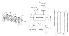
- FIG. 1is a perspective view of a bed and mattress including the bed exit detecting system of the described embodiments;
- FIG. 2is a schematic diagram of the bed exit detecting system
- FIG. 3is a perspective view of a baffled bolster.
- the bed exit detecting systemincludes a pair of bolster air cells 12 respectively positionable adjacent opposite sides of a mattress M. Although a pneumatic mattress M is shown, the bed exit detecting system may be configurable for operation with a conventional mattress.
- the system componentsare preferably secured within a housing 14 .
- the systemincludes a pressure source 16 , such as a pump, in fluid communication with the bolster air cells 12 .
- a pressure sensor 18such as a pressure transducer, is connected directly with the bolster air cells 12 via tubing or the like.
- a signal processor 20such as a microcontroller, communicates with the pressure sensor 18 and the pressure source 16 and includes an alarm 22 that is activated when a predetermined pressure change (increase) in one of the air cells 12 is detected by the pressure sensor 18 . It is preferable that the bolster air cells 12 extend along a full length of the mattress end as shown, although a shorter length could be conceivable depending on side rail arrangements of the bed frame F.
- the signal processor 20is programmed to maintain a predetermined pressure, such as 50 mmHg in the air cells 12 via the pressure source 16 .
- the signal processor 20controls a solenoid valve 24 to connect the pressure source 16 with the air cells 12 .
- a signalis sent to the alarm 22 .
- the pressure changecould be a fixed value, e.g., 7 mmHg, or calculated internally based on patient weight and desired sensitivity.
- the signal processor 20is programmed to activate the alarm 22 when the predetermined pressure change is detected for a predetermined period of time.
- An exemplary period of timeis about 5 seconds. With the pressure increase over the specified time, a clear indication of bed or chair egress or an entrapment issue can be detected.
- the pressure sensor 18is connected directly to the air cells 12 via tubing or the like. This allows accurate and immediate (within microseconds) measurement of pressure changes.
- the sensor signalis digitized via an analog-to-digital (A/D) converter.
- the signalmay be amplified via an amplifier 28 , or used as is, and is read by the signal processor 20 .
- the signal processor 20monitors the pressure changes and, in the preferred embodiment, also monitors time. As noted, when certain parameters are met, the processor sends a signal to the alarm 22 for alarm notification.
- This systemis advantageous relative to other systems in that it has the ability to signal an alarm BEFORE the patient actually leaves the bed or chair. As the patient tries to get out of bed, the patient's weight rests on the long side bolsters, causing the change in pressure and therefore setting off the alarm. This occurs before the patient is actually off the mattress and out of bed.
- This systemwill also sound the alarm if the bolster pressure increases when a patient is caught between the side rails of the frame and the bed mattress. This entrapment is of great concern to care givers as such entrapment can lead to serious injuries, sometimes even causing death.
- a simple “overlay” 30 including a flat sheet with attached side bolsters 12could be placed directly on any hospital mattress, with a small electronic controller containing the compressor pump, sensors and a microprocessor attached to the bed frame F and connected to the inflatable side bolsters 12 via tubing.
- the bolster air cells 12can be of a singular tube like construction, but these tend to have a large round cross section and take up too much room between the side rails.
- An alternative bolstermay be a baffled bolster 32 shown in FIG. 3 , which would have a cross section higher than wide, therefore providing enough height over the mattress, but not taking up too much room between the side rails.
- the exact size and design of the bolsters, as well as the bolster set pressure, and the pressure change in the air cells for a set period of timecan vary according to requirements.
Landscapes
- Health & Medical Sciences (AREA)
- Life Sciences & Earth Sciences (AREA)
- Veterinary Medicine (AREA)
- Animal Behavior & Ethology (AREA)
- General Health & Medical Sciences (AREA)
- Public Health (AREA)
- Physics & Mathematics (AREA)
- Engineering & Computer Science (AREA)
- Dentistry (AREA)
- Oral & Maxillofacial Surgery (AREA)
- Nursing (AREA)
- Biophysics (AREA)
- Pathology (AREA)
- Physiology (AREA)
- Biomedical Technology (AREA)
- Heart & Thoracic Surgery (AREA)
- Medical Informatics (AREA)
- Molecular Biology (AREA)
- Surgery (AREA)
- Invalid Beds And Related Equipment (AREA)
- Measuring And Recording Apparatus For Diagnosis (AREA)
Abstract
Description
Claims (16)
Priority Applications (1)
| Application Number | Priority Date | Filing Date | Title |
|---|---|---|---|
| US12/558,142US8042206B2 (en) | 2009-09-11 | 2009-09-11 | Bed exit alarm |
Applications Claiming Priority (1)
| Application Number | Priority Date | Filing Date | Title |
|---|---|---|---|
| US12/558,142US8042206B2 (en) | 2009-09-11 | 2009-09-11 | Bed exit alarm |
Publications (2)
| Publication Number | Publication Date |
|---|---|
| US20110061164A1 US20110061164A1 (en) | 2011-03-17 |
| US8042206B2true US8042206B2 (en) | 2011-10-25 |
Family
ID=43729015
Family Applications (1)
| Application Number | Title | Priority Date | Filing Date |
|---|---|---|---|
| US12/558,142Expired - Fee RelatedUS8042206B2 (en) | 2009-09-11 | 2009-09-11 | Bed exit alarm |
Country Status (1)
| Country | Link |
|---|---|
| US (1) | US8042206B2 (en) |
Cited By (11)
| Publication number | Priority date | Publication date | Assignee | Title |
|---|---|---|---|---|
| US10260933B2 (en) | 2015-06-30 | 2019-04-16 | Stryker Corporation | Person support apparatuses with load cell error detection |
| US10330522B2 (en) | 2015-12-17 | 2019-06-25 | Stryker Corporation | Person support apparatus with exit detection system and/or scale system |
| US10357185B2 (en) | 2014-10-17 | 2019-07-23 | Stryker Corporation | Person support apparatuses with motion monitoring |
| US10617327B2 (en) | 2014-11-06 | 2020-04-14 | Stryker Corporation | Exit detection system with compensation |
| US10786408B2 (en) | 2014-10-17 | 2020-09-29 | Stryker Corporation | Person support apparatuses with exit detection systems |
| US10987262B2 (en) | 2013-03-15 | 2021-04-27 | Stryker Corporation | Medical support apparatus |
| US11052005B2 (en) | 2017-09-19 | 2021-07-06 | Stryker Corporation | Patient support apparatus with handles for patient ambulation |
| US11116680B2 (en) | 2017-09-19 | 2021-09-14 | Stryker Corporation | Patient support apparatus for controlling patient ingress and egress |
| US11160705B2 (en) | 2017-10-20 | 2021-11-02 | Stryker Corporation | Adjustable patient support apparatus for assisted egress and ingress |
| US11191687B2 (en)* | 2017-04-29 | 2021-12-07 | Harikrishan S. Sachdev | Portable cushion and method of use |
| US12408845B2 (en) | 2019-08-20 | 2025-09-09 | Stryker Corporation | Person support apparatus with adjustable exit detection zones |
Families Citing this family (6)
| Publication number | Priority date | Publication date | Assignee | Title |
|---|---|---|---|---|
| EP2763642B1 (en)* | 2011-10-03 | 2016-11-16 | Huntleigh Technology Limited | Multi-layered support system with electrically conductive spacer material |
| US11246778B2 (en) | 2011-12-14 | 2022-02-15 | Paramount Bed Co., Ltd. | Bed apparatus and patient detection method |
| WO2014143634A1 (en)* | 2013-03-14 | 2014-09-18 | Nunn Rob | Inflatable air mattress system with detection techniques |
| US10220806B2 (en)* | 2017-08-02 | 2019-03-05 | Ford Global Technologies, Llc | Monitoring and alerting vehicle occupants for ignition systems |
| CN112716455A (en)* | 2020-12-28 | 2021-04-30 | 深圳数联天下智能科技有限公司 | Sleep monitor |
| US20240277544A1 (en)* | 2023-02-17 | 2024-08-22 | Stryker Corporation | Patient support apparatus with pump |
Citations (17)
| Publication number | Priority date | Publication date | Assignee | Title |
|---|---|---|---|---|
| US3533095A (en)* | 1969-01-02 | 1970-10-06 | James Collins | Inflatable pad with alarm |
| US4175263A (en)* | 1977-04-25 | 1979-11-20 | Triad & Associates, Inc. | Technique for monitoring whether an individual is moving from a particular area |
| US4179692A (en) | 1977-05-05 | 1979-12-18 | Vance Dwight A | Apparatus to indicate when a patient has evacuated a bed or demonstrates a restless condition |
| US4295133A (en) | 1977-05-05 | 1981-10-13 | Vance Dwight A | Apparatus to indicate when a patient has evacuated a bed or demonstrates a restless condition |
| US4484043A (en) | 1982-09-30 | 1984-11-20 | Bed-Check Corporation | Switch apparatus responsive to pressure or distortion |
| US4565910A (en) | 1982-09-30 | 1986-01-21 | Bed-Check Corporation | Switch apparatus responsive to distortion |
| US4700180A (en) | 1983-05-04 | 1987-10-13 | Vance Dwight A | Apparatus to indicate when a patient has evacuated a bed |
| US4907845A (en)* | 1988-09-16 | 1990-03-13 | Salomon Sa | Bed patient monitoring system |
| US5184112A (en)* | 1991-09-11 | 1993-02-02 | Gaymar Industries, Inc. | Bed patient position monitor |
| US5235319A (en) | 1992-05-11 | 1993-08-10 | Joseph C. Hill | Patient monitoring system |
| US5410297A (en) | 1993-01-11 | 1995-04-25 | R. F. Technologies, Inc. | Capacitive patient presence monitor |
| US6583727B2 (en)* | 2001-06-25 | 2003-06-24 | Colin Corporation | Patient detecting apparatus |
| US6778090B2 (en) | 1996-09-04 | 2004-08-17 | Paul Newham | Modular system for monitoring the presence of a person using a variety of sensing devices |
| US6877178B2 (en)* | 2001-03-15 | 2005-04-12 | Huntleigh Technology, Plc | Inflatable support |
| US20090183312A1 (en)* | 1998-10-28 | 2009-07-23 | Price James H | Patient support surface with vital signs sensors |
| US7656299B2 (en)* | 2007-01-17 | 2010-02-02 | Hoana Medical, Inc. | Bed exit and patient detection system |
| US7735171B2 (en)* | 2007-11-09 | 2010-06-15 | Apex Medical Corp. | Support structure with side guards |
- 2009
- 2009-09-11USUS12/558,142patent/US8042206B2/ennot_activeExpired - Fee Related
Patent Citations (17)
| Publication number | Priority date | Publication date | Assignee | Title |
|---|---|---|---|---|
| US3533095A (en)* | 1969-01-02 | 1970-10-06 | James Collins | Inflatable pad with alarm |
| US4175263A (en)* | 1977-04-25 | 1979-11-20 | Triad & Associates, Inc. | Technique for monitoring whether an individual is moving from a particular area |
| US4179692A (en) | 1977-05-05 | 1979-12-18 | Vance Dwight A | Apparatus to indicate when a patient has evacuated a bed or demonstrates a restless condition |
| US4295133A (en) | 1977-05-05 | 1981-10-13 | Vance Dwight A | Apparatus to indicate when a patient has evacuated a bed or demonstrates a restless condition |
| US4484043A (en) | 1982-09-30 | 1984-11-20 | Bed-Check Corporation | Switch apparatus responsive to pressure or distortion |
| US4565910A (en) | 1982-09-30 | 1986-01-21 | Bed-Check Corporation | Switch apparatus responsive to distortion |
| US4700180A (en) | 1983-05-04 | 1987-10-13 | Vance Dwight A | Apparatus to indicate when a patient has evacuated a bed |
| US4907845A (en)* | 1988-09-16 | 1990-03-13 | Salomon Sa | Bed patient monitoring system |
| US5184112A (en)* | 1991-09-11 | 1993-02-02 | Gaymar Industries, Inc. | Bed patient position monitor |
| US5235319A (en) | 1992-05-11 | 1993-08-10 | Joseph C. Hill | Patient monitoring system |
| US5410297A (en) | 1993-01-11 | 1995-04-25 | R. F. Technologies, Inc. | Capacitive patient presence monitor |
| US6778090B2 (en) | 1996-09-04 | 2004-08-17 | Paul Newham | Modular system for monitoring the presence of a person using a variety of sensing devices |
| US20090183312A1 (en)* | 1998-10-28 | 2009-07-23 | Price James H | Patient support surface with vital signs sensors |
| US6877178B2 (en)* | 2001-03-15 | 2005-04-12 | Huntleigh Technology, Plc | Inflatable support |
| US6583727B2 (en)* | 2001-06-25 | 2003-06-24 | Colin Corporation | Patient detecting apparatus |
| US7656299B2 (en)* | 2007-01-17 | 2010-02-02 | Hoana Medical, Inc. | Bed exit and patient detection system |
| US7735171B2 (en)* | 2007-11-09 | 2010-06-15 | Apex Medical Corp. | Support structure with side guards |
Cited By (16)
| Publication number | Priority date | Publication date | Assignee | Title |
|---|---|---|---|---|
| US11559448B2 (en) | 2013-03-15 | 2023-01-24 | Stryker Corporation | Medical support apparatus |
| US10987262B2 (en) | 2013-03-15 | 2021-04-27 | Stryker Corporation | Medical support apparatus |
| US10786408B2 (en) | 2014-10-17 | 2020-09-29 | Stryker Corporation | Person support apparatuses with exit detection systems |
| US10357185B2 (en) | 2014-10-17 | 2019-07-23 | Stryker Corporation | Person support apparatuses with motion monitoring |
| US10617327B2 (en) | 2014-11-06 | 2020-04-14 | Stryker Corporation | Exit detection system with compensation |
| US10260933B2 (en) | 2015-06-30 | 2019-04-16 | Stryker Corporation | Person support apparatuses with load cell error detection |
| US10612963B2 (en)* | 2015-12-17 | 2020-04-07 | Stryker Corporation | Person support apparatus with exit detection system and/or scale system |
| US20190310128A1 (en)* | 2015-12-17 | 2019-10-10 | Stryker Corporation | Person support apparatus with exit detection system and/or scale system |
| US10330522B2 (en) | 2015-12-17 | 2019-06-25 | Stryker Corporation | Person support apparatus with exit detection system and/or scale system |
| US11191687B2 (en)* | 2017-04-29 | 2021-12-07 | Harikrishan S. Sachdev | Portable cushion and method of use |
| US11052005B2 (en) | 2017-09-19 | 2021-07-06 | Stryker Corporation | Patient support apparatus with handles for patient ambulation |
| US11116680B2 (en) | 2017-09-19 | 2021-09-14 | Stryker Corporation | Patient support apparatus for controlling patient ingress and egress |
| US11723821B2 (en) | 2017-09-19 | 2023-08-15 | Stryker Corporation | Patient support apparatus for controlling patient ingress and egress |
| US11160705B2 (en) | 2017-10-20 | 2021-11-02 | Stryker Corporation | Adjustable patient support apparatus for assisted egress and ingress |
| US11806290B2 (en) | 2017-10-20 | 2023-11-07 | Stryker Corporation | Adjustable patient support apparatus for assisted egress and ingress |
| US12408845B2 (en) | 2019-08-20 | 2025-09-09 | Stryker Corporation | Person support apparatus with adjustable exit detection zones |
Also Published As
| Publication number | Publication date |
|---|---|
| US20110061164A1 (en) | 2011-03-17 |
Similar Documents
| Publication | Publication Date | Title |
|---|---|---|
| US8042206B2 (en) | Bed exit alarm | |
| US5780798A (en) | Bed occupant sensing device | |
| US6560804B2 (en) | System and methods for mattress control in relation to patient distance | |
| JP6496639B2 (en) | Patient holding device | |
| US4657026A (en) | Apnea alarm systems | |
| US5435317A (en) | Respiratory monitor and stimulus imparting device and method | |
| US7825814B2 (en) | Bed occupant monitoring system | |
| US5144284A (en) | Patient-monitoring bed covering device | |
| US6721980B1 (en) | Force optimization surface apparatus and method | |
| US4020482A (en) | Patient monitor | |
| CA3120317C (en) | Hospital bed with patient weight and displacement sensors | |
| US9015884B2 (en) | Head support for stopping snoring | |
| US20090106906A1 (en) | Self-contained gatching, rotating and adjustable foot section mattress | |
| WO2020026171A1 (en) | Sensing system for patient support apparatus | |
| KR101975473B1 (en) | System for preventing pressure sore | |
| JP2004049388A (en) | Equipment control system and bedsore prevention system | |
| CN114948501A (en) | A kind of automatic turning mattress and mattress control method | |
| JP2018187324A (en) | Movable bed system | |
| EP3231407B1 (en) | Support device with sensing elements | |
| JP2001037821A (en) | Sensor device of bed and bed using it | |
| US10254727B2 (en) | Feedback control for a person support apparatus with a mattress replacement system and methods for automatically pausing a turn and hold operation | |
| US20080150730A1 (en) | Infant remote monitoring system | |
| JP3884660B2 (en) | Body motion detection device | |
| WO2004073577A1 (en) | Pad | |
| AU8077391A (en) | Micro Movement Detector |
Legal Events
| Date | Code | Title | Description |
|---|---|---|---|
| AS | Assignment | Owner name:ANODYNE MEDICAL DEVICE, INC., FLORIDA Free format text:ASSIGNMENT OF ASSIGNORS INTEREST;ASSIGNOR:GENARO, DAVID M.;REEL/FRAME:023221/0172 Effective date:20090910 | |
| ZAAA | Notice of allowance and fees due | Free format text:ORIGINAL CODE: NOA | |
| ZAAB | Notice of allowance mailed | Free format text:ORIGINAL CODE: MN/=. | |
| STCF | Information on status: patent grant | Free format text:PATENTED CASE | |
| CC | Certificate of correction | ||
| FPAY | Fee payment | Year of fee payment:4 | |
| AS | Assignment | Owner name:JPMORGAN CHASE BANK, N.A., AS COLLATERAL AGENT, IL Free format text:SECURITY AGREEMENT;ASSIGNOR:ANODYNE MEDICAL DEVICE, INC.;REEL/FRAME:040621/0584 Effective date:20161114 | |
| MAFP | Maintenance fee payment | Free format text:PAYMENT OF MAINTENANCE FEE, 8TH YEAR, LARGE ENTITY (ORIGINAL EVENT CODE: M1552); ENTITY STATUS OF PATENT OWNER: LARGE ENTITY Year of fee payment:8 | |
| AS | Assignment | Owner name:MORTARA INSTRUMENT SERVICES, INC., WISCONSIN Free format text:RELEASE BY SECURED PARTY;ASSIGNOR:JPMORGAN CHASE BANK, N.A.;REEL/FRAME:050254/0513 Effective date:20190830 Owner name:HILL-ROM COMPANY, INC., ILLINOIS Free format text:RELEASE BY SECURED PARTY;ASSIGNOR:JPMORGAN CHASE BANK, N.A.;REEL/FRAME:050254/0513 Effective date:20190830 Owner name:ALLEN MEDICAL SYSTEMS, INC., ILLINOIS Free format text:RELEASE BY SECURED PARTY;ASSIGNOR:JPMORGAN CHASE BANK, N.A.;REEL/FRAME:050254/0513 Effective date:20190830 Owner name:VOALTE, INC., FLORIDA Free format text:RELEASE BY SECURED PARTY;ASSIGNOR:JPMORGAN CHASE BANK, N.A.;REEL/FRAME:050254/0513 Effective date:20190830 Owner name:WELCH ALLYN, INC., NEW YORK Free format text:RELEASE BY SECURED PARTY;ASSIGNOR:JPMORGAN CHASE BANK, N.A.;REEL/FRAME:050254/0513 Effective date:20190830 Owner name:HILL-ROM, INC., ILLINOIS Free format text:RELEASE BY SECURED PARTY;ASSIGNOR:JPMORGAN CHASE BANK, N.A.;REEL/FRAME:050254/0513 Effective date:20190830 Owner name:ANODYNE MEDICAL DEVICE, INC., FLORIDA Free format text:RELEASE BY SECURED PARTY;ASSIGNOR:JPMORGAN CHASE BANK, N.A.;REEL/FRAME:050254/0513 Effective date:20190830 Owner name:MORTARA INSTRUMENT, INC., WISCONSIN Free format text:RELEASE BY SECURED PARTY;ASSIGNOR:JPMORGAN CHASE BANK, N.A.;REEL/FRAME:050254/0513 Effective date:20190830 Owner name:HILL-ROM SERVICES, INC., ILLINOIS Free format text:RELEASE BY SECURED PARTY;ASSIGNOR:JPMORGAN CHASE BANK, N.A.;REEL/FRAME:050254/0513 Effective date:20190830 | |
| AS | Assignment | Owner name:JPMORGAN CHASE BANK, N.A., ILLINOIS Free format text:SECURITY AGREEMENT;ASSIGNORS:HILL-ROM HOLDINGS, INC.;HILL-ROM, INC.;HILL-ROM SERVICES, INC.;AND OTHERS;REEL/FRAME:050260/0644 Effective date:20190830 | |
| AS | Assignment | Owner name:HILL-ROM HOLDINGS, INC., ILLINOIS Free format text:RELEASE OF SECURITY INTEREST AT REEL/FRAME 050260/0644;ASSIGNOR:JPMORGAN CHASE BANK, N.A.;REEL/FRAME:058517/0001 Effective date:20211213 Owner name:BARDY DIAGNOSTICS, INC., ILLINOIS Free format text:RELEASE OF SECURITY INTEREST AT REEL/FRAME 050260/0644;ASSIGNOR:JPMORGAN CHASE BANK, N.A.;REEL/FRAME:058517/0001 Effective date:20211213 Owner name:VOALTE, INC., FLORIDA Free format text:RELEASE OF SECURITY INTEREST AT REEL/FRAME 050260/0644;ASSIGNOR:JPMORGAN CHASE BANK, N.A.;REEL/FRAME:058517/0001 Effective date:20211213 Owner name:HILL-ROM, INC., ILLINOIS Free format text:RELEASE OF SECURITY INTEREST AT REEL/FRAME 050260/0644;ASSIGNOR:JPMORGAN CHASE BANK, N.A.;REEL/FRAME:058517/0001 Effective date:20211213 Owner name:WELCH ALLYN, INC., NEW YORK Free format text:RELEASE OF SECURITY INTEREST AT REEL/FRAME 050260/0644;ASSIGNOR:JPMORGAN CHASE BANK, N.A.;REEL/FRAME:058517/0001 Effective date:20211213 Owner name:ALLEN MEDICAL SYSTEMS, INC., ILLINOIS Free format text:RELEASE OF SECURITY INTEREST AT REEL/FRAME 050260/0644;ASSIGNOR:JPMORGAN CHASE BANK, N.A.;REEL/FRAME:058517/0001 Effective date:20211213 Owner name:HILL-ROM SERVICES, INC., ILLINOIS Free format text:RELEASE OF SECURITY INTEREST AT REEL/FRAME 050260/0644;ASSIGNOR:JPMORGAN CHASE BANK, N.A.;REEL/FRAME:058517/0001 Effective date:20211213 Owner name:BREATHE TECHNOLOGIES, INC., CALIFORNIA Free format text:RELEASE OF SECURITY INTEREST AT REEL/FRAME 050260/0644;ASSIGNOR:JPMORGAN CHASE BANK, N.A.;REEL/FRAME:058517/0001 Effective date:20211213 | |
| FEPP | Fee payment procedure | Free format text:MAINTENANCE FEE REMINDER MAILED (ORIGINAL EVENT CODE: REM.); ENTITY STATUS OF PATENT OWNER: LARGE ENTITY | |
| LAPS | Lapse for failure to pay maintenance fees | Free format text:PATENT EXPIRED FOR FAILURE TO PAY MAINTENANCE FEES (ORIGINAL EVENT CODE: EXP.); ENTITY STATUS OF PATENT OWNER: LARGE ENTITY | |
| STCH | Information on status: patent discontinuation | Free format text:PATENT EXPIRED DUE TO NONPAYMENT OF MAINTENANCE FEES UNDER 37 CFR 1.362 | |
| FP | Lapsed due to failure to pay maintenance fee | Effective date:20231025 |