US8041991B2 - System and method for recovering solid state drive data - Google Patents
System and method for recovering solid state drive dataDownload PDFInfo
- Publication number
- US8041991B2 US8041991B2US12/313,205US31320508AUS8041991B2US 8041991 B2US8041991 B2US 8041991B2US 31320508 AUS31320508 AUS 31320508AUS 8041991 B2US8041991 B2US 8041991B2
- Authority
- US
- United States
- Prior art keywords
- ssd
- data
- data blocks
- failed
- operational
- Prior art date
- Legal status (The legal status is an assumption and is not a legal conclusion. Google has not performed a legal analysis and makes no representation as to the accuracy of the status listed.)
- Expired - Fee Related, expires
Links
Images


Classifications
- G—PHYSICS
- G06—COMPUTING OR CALCULATING; COUNTING
- G06F—ELECTRIC DIGITAL DATA PROCESSING
- G06F11/00—Error detection; Error correction; Monitoring
- G06F11/07—Responding to the occurrence of a fault, e.g. fault tolerance
- G06F11/08—Error detection or correction by redundancy in data representation, e.g. by using checking codes
- G—PHYSICS
- G06—COMPUTING OR CALCULATING; COUNTING
- G06F—ELECTRIC DIGITAL DATA PROCESSING
- G06F11/00—Error detection; Error correction; Monitoring
- G06F11/07—Responding to the occurrence of a fault, e.g. fault tolerance
- G06F11/16—Error detection or correction of the data by redundancy in hardware
- G06F11/1658—Data re-synchronization of a redundant component, or initial sync of replacement, additional or spare unit
- G06F11/1662—Data re-synchronization of a redundant component, or initial sync of replacement, additional or spare unit the resynchronized component or unit being a persistent storage device
- G—PHYSICS
- G06—COMPUTING OR CALCULATING; COUNTING
- G06F—ELECTRIC DIGITAL DATA PROCESSING
- G06F11/00—Error detection; Error correction; Monitoring
- G06F11/07—Responding to the occurrence of a fault, e.g. fault tolerance
- G06F11/16—Error detection or correction of the data by redundancy in hardware
- G06F11/20—Error detection or correction of the data by redundancy in hardware using active fault-masking, e.g. by switching out faulty elements or by switching in spare elements
- G06F11/2053—Error detection or correction of the data by redundancy in hardware using active fault-masking, e.g. by switching out faulty elements or by switching in spare elements where persistent mass storage functionality or persistent mass storage control functionality is redundant
- G06F11/2094—Redundant storage or storage space
- G—PHYSICS
- G06—COMPUTING OR CALCULATING; COUNTING
- G06F—ELECTRIC DIGITAL DATA PROCESSING
- G06F12/00—Accessing, addressing or allocating within memory systems or architectures
- G06F12/16—Protection against loss of memory contents
- G—PHYSICS
- G11—INFORMATION STORAGE
- G11C—STATIC STORES
- G11C29/00—Checking stores for correct operation ; Subsequent repair; Testing stores during standby or offline operation
- G11C29/52—Protection of memory contents; Detection of errors in memory contents
- G—PHYSICS
- G06—COMPUTING OR CALCULATING; COUNTING
- G06F—ELECTRIC DIGITAL DATA PROCESSING
- G06F2201/00—Indexing scheme relating to error detection, to error correction, and to monitoring
- G06F2201/84—Using snapshots, i.e. a logical point-in-time copy of the data
Definitions
- SSDsSolid state drives
- NAND technologies that the drives are based onhave a limited number or program/erase cycles. Over time, SSDs may reach a point where an erase cycle fails to reset a NAND flash block to a writable state. Such an SSD may be said to be failed.
- Current disk array controllers designed to handle traditional spindle-based disk drivesmay employ failure modes that affect both reading and writing, rendering the drives useless.
- SSDmay employ a read-only failure mode that allows the drive to execute read commands successfully even though write commands result in a failure.
- a read-only failure modethat allows the drive to execute read commands successfully even though write commands result in a failure.
- controllerscan not effectively utilize the read-only failure mode of SSDs.
- the present disclosureis directed to a system and method for recovering solid state drive (SSD) data.
- SSDsolid state drive
- a method for recovering solid state drive (SSD) datamay comprise: detecting a failed SSD comprising one or more data blocks; receiving a request to write data to the one or more data blocks of the failed SSD; writing the data to one or more data blocks of an operational drive; and rebuilding the failed SSD from the failed SSD and the one or more data blocks of the operational drive.
- SSDsolid state drive
- a system for recovering solid state drive (SSD) datamay comprise: means for detecting a failed SSD comprising one or more data blocks; means for receiving a request to write data to the one or more data blocks of the failed SSD; means for writing the data to one or more data blocks of an operational drive; and means for rebuilding the failed SSD from the failed SSD and the one or more data blocks of the operational drive.
- SSDsolid state drive
- FIG. 1shows a high-level block system for recovering solid state drive (SSD) data.
- SSDsolid state drive
- FIG. 2shows a process for recovering solid state drive (SSD) data.
- FIG. 3shows a process for recovering solid state drive (SSD) data.
- FIG. 4shows a process for recovering solid state drive (SSD) data.
- FIG. 5shows a process for recovering solid state drive (SSD) data.
- FIG. 6shows a process for recovering solid state drive (SSD) data.
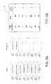
- FIG. 7Ashows an SSD configuration
- FIG. 7Bshows a look-up table configuration
- FIG. 8Ashows an SSD configuration
- FIG. 8Bshows a look-up table configuration
- FIG. 1illustrates an example system in which one or more technologies may be implemented.
- a data storage system 100comprising a computing device 101 , an array controller 102 , and a drive array 103 is shown.
- the array controller 102may include drive management circuitry/software whereby the array controller 102 can process read/write requests of the computing device 101 accessing various drives of the drive array 103 .
- the drive array 103may include a one or more drives including at least one SSD 104 and at least one operational drive 105 .
- the operational drive 105may be an SSD or a hard disk drive (HDD).
- FIG. 2illustrates an operational flow 200 representing example operations related to SSD recovery.
- discussion and explanationmay be provided with respect to the above-described examples of FIG. 1 , and/or with respect to other examples and contexts.
- the operational flowsmay be executed in a number of other environments and contexts, and/or in modified versions of FIG. 1 .
- the various operational flowsare presented in the sequence(s) illustrated, it should be understood that the various operations may be performed in other orders than those that are illustrated, or may be performed concurrently.
- the operation 210illustrates detecting a failed SSD comprising one or more data blocks.
- the array controller 102may detect that the drive array 103 is no longer capable of processing write instructions to a data block 106 of the drive array 103 .
- Operation 220illustrates receiving a request to write data to the one or more data blocks of the failed SSD.
- the array controller 102may receive a request from the computing device 101 to write data to the data block 106 of the SSD 104 .
- Operation 230illustrates writing the data to one or more data blocks of an operational drive.
- the array controller 102may cause the drive array 103 to write data to a data block 107 of the operational drive 105 .
- Operation 240illustrates rebuilding the failed SSD from the failed SSD and the one or more data blocks of the operational drive.
- the array controller 102may rebuild the SSD 104 from the current contents of the SSD 104 and the operational drive 105 to the replacement SSD 111 .
- FIG. 3illustrates alternative embodiments of the example operational flow 200 of FIG. 2 .
- FIG. 3illustrates example embodiments where the detecting operation 210 may include at least one additional operation. Additional operations may include an operation 302 .
- Operation 302illustrates detecting a failed write directed to one or more data blocks of the SSD.
- the array controller 102may detect that the drive array 103 is no longer capable of processing write instructions directed to a data block 106 of the SSD 104 .
- FIG. 4illustrates alternative embodiments of the example operational flow 200 of FIG. 2 .
- FIG. 4illustrates example embodiments where the operational flow 200 may include at least one additional operation. Additional operations may include an operation 402 and/or an operation 404 .
- Operation 402illustrates writing the data to one or more data blocks of an operational drive according to a redirect-on-write snapshot methodology.
- the array controller 102may cause the SSD 104 to place newly written data in a different location than previously written copy of the same data.
- multiple data segmentsmay be written to SSD 104 .
- the operational drive 105may be an SSD that has been erased and is ready to be written.
- look-up table 108 Amay maintain the mappings of the data blocks to their respective flash blocks and pages.
- the array controller 102may receive a write command for segments 210 and 211 of the SSD 104 . Should one or more data blocks of the SSD 104 be detected as failed, the data storage system 100 may employ a redirect-on-write snapshot methodology to maintain the integrity of data in the SSD 104 .
- the array controller 102may accept the new data for segments 210 and 211 and write it to pre-erased areas of the operational drive 105 .
- the SSD 104may remain unchanged ( FIG. 8A is modified to show that the data for blocks 210 and 211 in SSD 104 is “old” data).
- the state of the operational drive 105is as shown in FIG. 8A .
- the old copies of data segments 210 and 211may remain in the SSD 104 until the entire SSD 104 is reclaimed and erased in preparation for reuse.
- the look-up table 108 A in the array controller 102may be updated to reflect the new addresses for data segments 210 and 211 and appear as shown in FIG. 8B .
- Operation 404illustrates updating one or more look-up tables comprising data block mappings for the failed SSD and an operational SSD.
- the array controller 102may include one or more look-up tables (e.g. look-up table 108 A and look-up table 108 B) which maintain mapping lists of memory block elements and their respective flash addresses in the SSD 104 and/or the operational drive 105 .
- the SSD 104may execute a redirect-on-write for every write command received, the SSD 104 may retain a previous copy of user data that can be used to reconstruct both current data or prior snapshot data at no loss in performance.
- the data storage system 100may provide access to multiple point-in-time copies of the data stored in the device.
- the array controller 102may receive a command to store a point in time copy of the data prior to the write of segments 210 and 211 .
- the array controller 102may retain a copy of the lookup table 108 A for the SSD addresses shown in FIG. 7A as the pointers to the addresses for the point in time copy.
- the pointers for the current view of the data as shown in FIG. 8Amay be maintained in the second look-up table 108 B.
- the array controller 102may keep a copy of both tables so long as it has space for the snapshot and the snapshot is not ended via some other action.
- FIG. 5illustrates alternative embodiments of the example operational flow 200 of FIG. 2 .
- FIG. 5illustrates example embodiments where the rebuilding operation 240 may include at least one additional operation. Additional operations may include an operation 502 and/or an operation 504 .
- Operation 502illustrates copying one or more data blocks of the failed SSD for which write requests have not been received to a replacement SSD.
- the array controller 102may cause those portions of SSD 104 that have not been addressed by write requests (e.g. unmodified data block 109 ) to be copied to a data block 110 of a replacement SSD 111 .
- Operation 504illustrates copying the one or more data blocks of the operational drive to the replacement SSD.
- the array controller 102may cause those portions of operational drive 105 which have been written in response to failed write operations directed to the SSD 104 (e.g. data block 107 ) to be copied to a data block 112 of the replacement SSD 111 .
- FIG. 6illustrates alternative embodiments of the example operational flow 200 of FIG. 2 .
- FIG. 6illustrates example embodiments where the operational flow 200 may include at least one additional operation. Additional operations may include an operation 610 .
- Operation 610illustrates redirecting a read request directed to the one or more data blocks of the operational drive to one or more data blocks of the replacement SSD.
- the operational drive 105may comprise a HDD.
- the array controller 102may maintain a pointer to the extent of data that has been written to the replacement SSD 111 .
- the array controller 102may direct the read request to the replacement SSD 111 .
- the replacement SSD 111may be able to service a potion of the IO stream that would have been serviced by the HDD operational drive 105 and SSD 104 prior to its failure thereby maintaining an increased level of performance as compared to the situation where the IO was serviced by the HDD operational drive 105 .
- Examples of a signal bearing mediuminclude, but are not limited to, the following: a recordable type medium such as a floppy disk, a hard disk drive, a Compact Disc (CD), a Digital Video Disk (DVD), a digital tape, a computer memory, etc.; and a transmission type medium such as a digital and/or an analog communication medium (e.g., a fiber optic cable, a waveguide, a wired communications link, a wireless communication link (e.g., transmitter, receiver, transmission logic, reception logic, etc.), etc.).
- a recordable type mediumsuch as a floppy disk, a hard disk drive, a Compact Disc (CD), a Digital Video Disk (DVD), a digital tape, a computer memory, etc.
- a transmission type mediumsuch as a digital and/or an analog communication medium (e.g., a fiber optic cable, a waveguide, a wired communications link, a wireless communication link (e.g., transmitter, receiver, transmission logic, reception
- an implementermay opt for a mainly hardware and/or firmware vehicle; alternatively, if flexibility is paramount, the implementer may opt for a mainly software implementation; or, yet again alternatively, the implementer may opt for some combination of hardware, software, and/or firmware.
- any vehicle to be utilizedis a choice dependent upon the context in which the vehicle will be deployed and the specific concerns (e.g., speed, flexibility, or predictability) of the implementer, any of which may vary.
- Those skilled in the artwill recognize that optical aspects of implementations will typically employ optically-oriented hardware, software, and or firmware.
Landscapes
- Engineering & Computer Science (AREA)
- Theoretical Computer Science (AREA)
- Physics & Mathematics (AREA)
- General Engineering & Computer Science (AREA)
- General Physics & Mathematics (AREA)
- Quality & Reliability (AREA)
- Techniques For Improving Reliability Of Storages (AREA)
- Debugging And Monitoring (AREA)
- Signal Processing For Digital Recording And Reproducing (AREA)
Abstract
Description
Claims (15)
Priority Applications (7)
| Application Number | Priority Date | Filing Date | Title |
|---|---|---|---|
| US12/313,205US8041991B2 (en) | 2008-11-18 | 2008-11-18 | System and method for recovering solid state drive data |
| PCT/US2009/001986WO2010059173A1 (en) | 2008-11-18 | 2009-03-31 | System and method for recovering solid state drive data |
| CN200980142288.3ACN102197438B (en) | 2008-11-18 | 2009-03-31 | System and method for recovering solid state drive data |
| JP2011536302AJP2012509521A (en) | 2008-11-18 | 2009-03-31 | System and method for recovering solid state drive data |
| EP20090827843EP2356658A4 (en) | 2008-11-18 | 2009-03-31 | System and method for recovering solid state drive data |
| KR1020117011169AKR20110091677A (en) | 2008-11-18 | 2009-03-31 | System and method for recovering solid state drive data |
| TW098110964ATWI442225B (en) | 2008-11-18 | 2009-04-02 | System and method for recovering solid state drive data |
Applications Claiming Priority (1)
| Application Number | Priority Date | Filing Date | Title |
|---|---|---|---|
| US12/313,205US8041991B2 (en) | 2008-11-18 | 2008-11-18 | System and method for recovering solid state drive data |
Publications (2)
| Publication Number | Publication Date |
|---|---|
| US20100125751A1 US20100125751A1 (en) | 2010-05-20 |
| US8041991B2true US8041991B2 (en) | 2011-10-18 |
Family
ID=42172910
Family Applications (1)
| Application Number | Title | Priority Date | Filing Date |
|---|---|---|---|
| US12/313,205Expired - Fee RelatedUS8041991B2 (en) | 2008-11-18 | 2008-11-18 | System and method for recovering solid state drive data |
Country Status (7)
| Country | Link |
|---|---|
| US (1) | US8041991B2 (en) |
| EP (1) | EP2356658A4 (en) |
| JP (1) | JP2012509521A (en) |
| KR (1) | KR20110091677A (en) |
| CN (1) | CN102197438B (en) |
| TW (1) | TWI442225B (en) |
| WO (1) | WO2010059173A1 (en) |
Cited By (13)
| Publication number | Priority date | Publication date | Assignee | Title |
|---|---|---|---|---|
| US20120215966A1 (en)* | 2011-02-22 | 2012-08-23 | Nec Corporation | Disk array unit and control method thereof |
| US20130318392A1 (en)* | 2012-05-23 | 2013-11-28 | Fujitsu Limited | Information processing apparatus, control method |
| US8631191B2 (en) | 2011-03-10 | 2014-01-14 | Kabushiki Kaisha Toshiba | Information processing device, external storage device, host device, relay device, control program, and control method of information processing device |
| US9122587B2 (en) | 2013-03-06 | 2015-09-01 | Seagate Technology Llc | Self recovery in a solid state drive |
| US20170038985A1 (en)* | 2013-03-14 | 2017-02-09 | Seagate Technology Llc | Nonvolatile memory data recovery after power failure |
| US9946616B2 (en) | 2014-01-29 | 2018-04-17 | Hitachi, Ltd. | Storage apparatus |
| US10013322B2 (en) | 2013-06-03 | 2018-07-03 | Hitachi, Ltd. | Storage apparatus and storage apparatus control method |
| US10013171B2 (en) | 2015-06-29 | 2018-07-03 | International Business Machines Corporation | Reducing stress on RAIDS under rebuild |
| US10204003B2 (en) | 2014-08-27 | 2019-02-12 | Hitachi, Ltd. | Memory device and storage apparatus |
| US10372558B2 (en) | 2016-05-02 | 2019-08-06 | Samsung Electronics Co., Ltd. | Storage device, an operating method of the storage device and an operating method of a computing system including the storage device and a host device |
| US10445200B2 (en) | 2016-05-02 | 2019-10-15 | Samsung Electronics Co., Ltd. | Storage device having various recovery methods and recovery modes |
| USRE50129E1 (en) | 2016-05-02 | 2024-09-17 | Samsung Electronics Co., Ltd. | Storage device having various recovery methods and recovery modes |
| US12271611B2 (en) | 2022-01-07 | 2025-04-08 | Samsung Electronics Co., Ltd. | Method of operating a storage device including detecting an abnormal area, where an access time exceeds a reference latency, as an optional area in the nonvolatile memory device and storing optional data in the optional area, and a storage device for performing the method |
Families Citing this family (20)
| Publication number | Priority date | Publication date | Assignee | Title |
|---|---|---|---|---|
| US8230255B2 (en)* | 2009-12-15 | 2012-07-24 | International Business Machines Corporation | Blocking write acces to memory modules of a solid state drive |
| US8626713B2 (en) | 2010-12-08 | 2014-01-07 | International Business Machines Corporation | Multiple contexts in a redirect on write file system |
| US8396832B2 (en) | 2010-12-08 | 2013-03-12 | International Business Machines Corporation | Independent fileset generations in a clustered redirect-on-write filesystem |
| US8904006B2 (en) | 2010-12-08 | 2014-12-02 | International Business Machines Corporation | In-flight block map for a clustered redirect-on-write filesystem |
| US8458181B2 (en) | 2010-12-08 | 2013-06-04 | International Business Machines Corporation | Distributed free block map for a clustered redirect-on-write file system |
| CN102033793A (en)* | 2010-12-14 | 2011-04-27 | 成都市华为赛门铁克科技有限公司 | Snapshot method and solid-state hard disk |
| WO2014021823A1 (en)* | 2012-07-30 | 2014-02-06 | Empire Technology Development Llc | Bad block compensation for solid state storage devices |
| WO2014057515A1 (en)* | 2012-10-10 | 2014-04-17 | Hitachi, Ltd. | Storage apparatus comprising snapshot function, and storage control method |
| JP6005566B2 (en)* | 2013-03-18 | 2016-10-12 | 株式会社東芝 | Information processing system, control program, and information processing apparatus |
| US9665479B2 (en) | 2014-02-11 | 2017-05-30 | Seagate Technology Llc | Managing response time |
| US10061667B2 (en)* | 2014-06-30 | 2018-08-28 | Hitachi, Ltd. | Storage system for a memory control method |
| US9575853B2 (en)* | 2014-12-12 | 2017-02-21 | Intel Corporation | Accelerated data recovery in a storage system |
| JP6489827B2 (en)* | 2014-12-26 | 2019-03-27 | キヤノン株式会社 | Image processing apparatus, image processing apparatus control method, and program |
| KR102106689B1 (en)* | 2018-03-09 | 2020-05-04 | 한국과학기술원 | Data availability ssd architecture for providing user data protection |
| KR102586741B1 (en)* | 2018-04-23 | 2023-10-11 | 에스케이하이닉스 주식회사 | Memory system and operating method thereof |
| US10996894B2 (en)* | 2019-07-17 | 2021-05-04 | International Business Machines Corporation | Application storage segmentation reallocation |
| US12306717B2 (en) | 2020-05-11 | 2025-05-20 | Samsung Electronics Co., Ltd. | Systems, methods, and devices for data recovery using parity space as recovery space |
| US12298853B2 (en) | 2020-05-11 | 2025-05-13 | Samsung Electronics Co., Ltd. | Systems, methods, and devices for data recovery with spare storage device and fault resilient storage device |
| US12321236B2 (en) | 2020-05-11 | 2025-06-03 | Samsung Electronics Co., Ltd. | Systems, methods, and devices for fault resilient storage |
| US11775391B2 (en) | 2020-07-13 | 2023-10-03 | Samsung Electronics Co., Ltd. | RAID system with fault resilient storage devices |
Citations (14)
| Publication number | Priority date | Publication date | Assignee | Title |
|---|---|---|---|---|
| US5701407A (en)* | 1992-08-26 | 1997-12-23 | Mitsubishi Denki Kabushiki Kaisha | Redundant array of disks with improved data reconstruction |
| US6427215B2 (en) | 1999-03-31 | 2002-07-30 | International Business Machines Corporation | Recovering and relocating unreliable disk sectors when encountering disk drive read errors |
| US6560718B1 (en)* | 1999-11-30 | 2003-05-06 | Stmicroelectronics, Inc. | Disk drive error recovery and defect management method |
| US20030237019A1 (en)* | 2002-06-24 | 2003-12-25 | Kleiman Steven R. | Using file system information in RAID data reconstruction and migration |
| US20060053338A1 (en)* | 2004-09-08 | 2006-03-09 | Copan Systems, Inc. | Method and system for disk drive exercise and maintenance of high-availability storage systems |
| US7028216B2 (en)* | 2003-11-26 | 2006-04-11 | Hitachi, Ltd. | Disk array system and a method of avoiding failure of the disk array system |
| US7149846B2 (en)* | 2002-04-17 | 2006-12-12 | Lsi Logic Corporation | RAID protected external secondary memory |
| US7197662B2 (en)* | 2002-10-31 | 2007-03-27 | Ring Technology Enterprises, Llc | Methods and systems for a storage system |
| US20070168698A1 (en) | 2005-11-03 | 2007-07-19 | Coulson Richard L | Recovering from a non-volatile memory failure |
| US20070180239A1 (en) | 2005-07-21 | 2007-08-02 | Akira Fujibayashi | Storage system for data encryption |
| US20080126712A1 (en)* | 2006-11-28 | 2008-05-29 | Hitachi, Ltd. | Semiconductor memory system having a snapshot function |
| US7490261B2 (en)* | 2003-12-18 | 2009-02-10 | Seagate Technology Llc | Background media scan for recovery of data errors |
| US20090063895A1 (en)* | 2007-09-04 | 2009-03-05 | Kurt Smith | Scaleable and maintainable solid state drive |
| US7711897B1 (en)* | 2005-06-10 | 2010-05-04 | American Megatrends, Inc. | Method, system, apparatus, and computer-readable medium for improving disk array performance |
Family Cites Families (8)
| Publication number | Priority date | Publication date | Assignee | Title |
|---|---|---|---|---|
| JPS6464047A (en)* | 1987-09-04 | 1989-03-09 | Fujitsu Ltd | Disk cache control system |
| US5088081A (en)* | 1990-03-28 | 1992-02-11 | Prime Computer, Inc. | Method and apparatus for improved disk access |
| JPH05120153A (en)* | 1991-10-24 | 1993-05-18 | Fujitsu Ltd | Alternate memory control system |
| JPH05150913A (en)* | 1991-11-29 | 1993-06-18 | Hitachi Ltd | Silicon disk with flash memory as storage medium |
| JP3561002B2 (en)* | 1994-05-18 | 2004-09-02 | 富士通株式会社 | Disk unit |
| JPH07325674A (en)* | 1994-06-01 | 1995-12-12 | Hitachi Ltd | Semiconductor memory replacement method and semiconductor disk subsystem control method |
| US6598174B1 (en)* | 2000-04-26 | 2003-07-22 | Dell Products L.P. | Method and apparatus for storage unit replacement in non-redundant array |
| JP2007199953A (en)* | 2006-01-25 | 2007-08-09 | Fujitsu Ltd | Disk array device and disk array control method |
- 2008
- 2008-11-18USUS12/313,205patent/US8041991B2/ennot_activeExpired - Fee Related
- 2009
- 2009-03-31WOPCT/US2009/001986patent/WO2010059173A1/enactiveApplication Filing
- 2009-03-31JPJP2011536302Apatent/JP2012509521A/ennot_activeCeased
- 2009-03-31CNCN200980142288.3Apatent/CN102197438B/ennot_activeExpired - Fee Related
- 2009-03-31KRKR1020117011169Apatent/KR20110091677A/ennot_activeAbandoned
- 2009-03-31EPEP20090827843patent/EP2356658A4/ennot_activeWithdrawn
- 2009-04-02TWTW098110964Apatent/TWI442225B/ennot_activeIP Right Cessation
Patent Citations (15)
| Publication number | Priority date | Publication date | Assignee | Title |
|---|---|---|---|---|
| US5701407A (en)* | 1992-08-26 | 1997-12-23 | Mitsubishi Denki Kabushiki Kaisha | Redundant array of disks with improved data reconstruction |
| US6427215B2 (en) | 1999-03-31 | 2002-07-30 | International Business Machines Corporation | Recovering and relocating unreliable disk sectors when encountering disk drive read errors |
| US6560718B1 (en)* | 1999-11-30 | 2003-05-06 | Stmicroelectronics, Inc. | Disk drive error recovery and defect management method |
| US7149846B2 (en)* | 2002-04-17 | 2006-12-12 | Lsi Logic Corporation | RAID protected external secondary memory |
| US20030237019A1 (en)* | 2002-06-24 | 2003-12-25 | Kleiman Steven R. | Using file system information in RAID data reconstruction and migration |
| US7024586B2 (en)* | 2002-06-24 | 2006-04-04 | Network Appliance, Inc. | Using file system information in raid data reconstruction and migration |
| US7197662B2 (en)* | 2002-10-31 | 2007-03-27 | Ring Technology Enterprises, Llc | Methods and systems for a storage system |
| US7028216B2 (en)* | 2003-11-26 | 2006-04-11 | Hitachi, Ltd. | Disk array system and a method of avoiding failure of the disk array system |
| US7490261B2 (en)* | 2003-12-18 | 2009-02-10 | Seagate Technology Llc | Background media scan for recovery of data errors |
| US20060053338A1 (en)* | 2004-09-08 | 2006-03-09 | Copan Systems, Inc. | Method and system for disk drive exercise and maintenance of high-availability storage systems |
| US7711897B1 (en)* | 2005-06-10 | 2010-05-04 | American Megatrends, Inc. | Method, system, apparatus, and computer-readable medium for improving disk array performance |
| US20070180239A1 (en) | 2005-07-21 | 2007-08-02 | Akira Fujibayashi | Storage system for data encryption |
| US20070168698A1 (en) | 2005-11-03 | 2007-07-19 | Coulson Richard L | Recovering from a non-volatile memory failure |
| US20080126712A1 (en)* | 2006-11-28 | 2008-05-29 | Hitachi, Ltd. | Semiconductor memory system having a snapshot function |
| US20090063895A1 (en)* | 2007-09-04 | 2009-03-05 | Kurt Smith | Scaleable and maintainable solid state drive |
Cited By (24)
| Publication number | Priority date | Publication date | Assignee | Title |
|---|---|---|---|---|
| US20120215966A1 (en)* | 2011-02-22 | 2012-08-23 | Nec Corporation | Disk array unit and control method thereof |
| US8683117B2 (en) | 2011-03-10 | 2014-03-25 | Kabushiki Kaisha Toshiba | Information processing device, external storage device, host device, relay device, control program, and control method of information processing device |
| US11880267B2 (en) | 2011-03-10 | 2024-01-23 | Kioxia Corporation | Information processing device, external storage device, host device, relay device, control program, and control method of information processing device |
| US8667216B2 (en) | 2011-03-10 | 2014-03-04 | Kabushiki Kaisha Toshiba | Information processing device, external storage device, host device, relay device, control program, and control method of information processing device |
| US10338985B2 (en) | 2011-03-10 | 2019-07-02 | Toshiba Memory Corporation | Information processing device, external storage device, host device, relay device, control program, and control method of information processing device |
| US8756367B2 (en) | 2011-03-10 | 2014-06-17 | Kabushiki Kaisha Toshiba | Information processing device, external storage device, host device, relay device, control program, and control method of information processing device |
| US10936394B2 (en) | 2011-03-10 | 2021-03-02 | Toshiba Memory Corporation | Information processing device, external storage device, host device, relay device, control program, and control method of information processing device |
| US8631191B2 (en) | 2011-03-10 | 2014-01-14 | Kabushiki Kaisha Toshiba | Information processing device, external storage device, host device, relay device, control program, and control method of information processing device |
| US11544131B2 (en) | 2011-03-10 | 2023-01-03 | Kioxia Corporation | Information processing device, external storage device, host device, relay device, control program, and control method of information processing device |
| US9201602B2 (en) | 2011-03-10 | 2015-12-01 | Kabushiki Kaisha Toshiba | Information processing device, external storage device, host device, relay device, control program, and control method of information processing device |
| US9785494B2 (en) | 2011-03-10 | 2017-10-10 | Toshiba Memory Corporation | Information processing device, external storage device, host device, relay device, control program, and control method of information processing device |
| US9176813B2 (en)* | 2012-05-23 | 2015-11-03 | Fujitsu Limited | Information processing apparatus, control method |
| US20130318392A1 (en)* | 2012-05-23 | 2013-11-28 | Fujitsu Limited | Information processing apparatus, control method |
| US9122587B2 (en) | 2013-03-06 | 2015-09-01 | Seagate Technology Llc | Self recovery in a solid state drive |
| US20170038985A1 (en)* | 2013-03-14 | 2017-02-09 | Seagate Technology Llc | Nonvolatile memory data recovery after power failure |
| US10048879B2 (en)* | 2013-03-14 | 2018-08-14 | Seagate Technology Llc | Nonvolatile memory recovery after power failure during write operations or erase operations |
| US10013322B2 (en) | 2013-06-03 | 2018-07-03 | Hitachi, Ltd. | Storage apparatus and storage apparatus control method |
| US9946616B2 (en) | 2014-01-29 | 2018-04-17 | Hitachi, Ltd. | Storage apparatus |
| US10204003B2 (en) | 2014-08-27 | 2019-02-12 | Hitachi, Ltd. | Memory device and storage apparatus |
| US10013171B2 (en) | 2015-06-29 | 2018-07-03 | International Business Machines Corporation | Reducing stress on RAIDS under rebuild |
| US10372558B2 (en) | 2016-05-02 | 2019-08-06 | Samsung Electronics Co., Ltd. | Storage device, an operating method of the storage device and an operating method of a computing system including the storage device and a host device |
| US10445200B2 (en) | 2016-05-02 | 2019-10-15 | Samsung Electronics Co., Ltd. | Storage device having various recovery methods and recovery modes |
| USRE50129E1 (en) | 2016-05-02 | 2024-09-17 | Samsung Electronics Co., Ltd. | Storage device having various recovery methods and recovery modes |
| US12271611B2 (en) | 2022-01-07 | 2025-04-08 | Samsung Electronics Co., Ltd. | Method of operating a storage device including detecting an abnormal area, where an access time exceeds a reference latency, as an optional area in the nonvolatile memory device and storing optional data in the optional area, and a storage device for performing the method |
Also Published As
| Publication number | Publication date |
|---|---|
| JP2012509521A (en) | 2012-04-19 |
| EP2356658A4 (en) | 2012-12-05 |
| CN102197438A (en) | 2011-09-21 |
| KR20110091677A (en) | 2011-08-12 |
| US20100125751A1 (en) | 2010-05-20 |
| TW201020760A (en) | 2010-06-01 |
| EP2356658A1 (en) | 2011-08-17 |
| CN102197438B (en) | 2014-03-05 |
| WO2010059173A1 (en) | 2010-05-27 |
| TWI442225B (en) | 2014-06-21 |
Similar Documents
| Publication | Publication Date | Title |
|---|---|---|
| US8041991B2 (en) | System and method for recovering solid state drive data | |
| US12353722B2 (en) | Information processing apparatus, method for controlling information processing apparatus, non-transitory recording medium storing control tool, host device, non-transitory recording medium storing performance evaluation tool, and performance evaluation method for external memory device | |
| US8285965B2 (en) | Aligning data storage device partition to boundary of physical data sector | |
| US7930499B2 (en) | Method to accelerate block level snapshots in archiving storage systems | |
| US8200922B2 (en) | Storage system snapshot assisted by SSD technology | |
| KR101475645B1 (en) | Information processing device, external storage device, host device, relay device, computer-readable recording medium, and control method of information processing device | |
| US9170756B2 (en) | Method and system for dynamic storage tiering using allocate-on-write snapshots | |
| US7352621B2 (en) | Method for enhanced block management | |
| KR101870521B1 (en) | Methods and systems for improving storage journaling | |
| US10120769B2 (en) | Raid rebuild algorithm with low I/O impact | |
| TWI423026B (en) | Data writing method, memory controller and memory storage apparatus | |
| US10521148B2 (en) | Data storage device backup | |
| US10901646B2 (en) | Update of RAID array parity | |
| KR20200113992A (en) | Apparatus and method for reducing cell disturb in open block of the memory system during receovery procedure | |
| KR20170023734A (en) | Methods and systems for improving flash memory flushing | |
| KR20200032527A (en) | Operating method of memory system and memory system | |
| US8938641B2 (en) | Method and apparatus for synchronizing storage volumes | |
| TWI493341B (en) | Memory storage device and repairing method thereof | |
| US9405668B1 (en) | Data storage device initialization information accessed by searching for pointer information | |
| US8688938B2 (en) | Data copying | |
| KR20170069053A (en) | Image Display Apparatus, Driving Method Thereof and Computer Readable Recording Medium | |
| HK1174414A (en) | Aligning data storage device partition to boundary of physical data sector |
Legal Events
| Date | Code | Title | Description |
|---|---|---|---|
| AS | Assignment | Owner name:LSI CORPORATION,CALIFORNIA Free format text:ASSIGNMENT OF ASSIGNORS INTEREST;ASSIGNOR:MCKEAN, BRIAN;REEL/FRAME:021899/0268 Effective date:20081117 Owner name:LSI CORPORATION, CALIFORNIA Free format text:ASSIGNMENT OF ASSIGNORS INTEREST;ASSIGNOR:MCKEAN, BRIAN;REEL/FRAME:021899/0268 Effective date:20081117 | |
| FEPP | Fee payment procedure | Free format text:PAYOR NUMBER ASSIGNED (ORIGINAL EVENT CODE: ASPN); ENTITY STATUS OF PATENT OWNER: LARGE ENTITY Free format text:PAYER NUMBER DE-ASSIGNED (ORIGINAL EVENT CODE: RMPN); ENTITY STATUS OF PATENT OWNER: LARGE ENTITY | |
| AS | Assignment | Owner name:DEUTSCHE BANK AG NEW YORK BRANCH, AS COLLATERAL AG Free format text:PATENT SECURITY AGREEMENT;ASSIGNORS:LSI CORPORATION;AGERE SYSTEMS LLC;REEL/FRAME:032856/0031 Effective date:20140506 | |
| AS | Assignment | Owner name:AVAGO TECHNOLOGIES GENERAL IP (SINGAPORE) PTE. LTD Free format text:ASSIGNMENT OF ASSIGNORS INTEREST;ASSIGNOR:LSI CORPORATION;REEL/FRAME:035390/0388 Effective date:20140814 | |
| REMI | Maintenance fee reminder mailed | ||
| LAPS | Lapse for failure to pay maintenance fees | ||
| STCH | Information on status: patent discontinuation | Free format text:PATENT EXPIRED DUE TO NONPAYMENT OF MAINTENANCE FEES UNDER 37 CFR 1.362 | |
| FP | Lapsed due to failure to pay maintenance fee | Effective date:20151018 | |
| AS | Assignment | Owner name:LSI CORPORATION, CALIFORNIA Free format text:TERMINATION AND RELEASE OF SECURITY INTEREST IN PATENT RIGHTS (RELEASES RF 032856-0031);ASSIGNOR:DEUTSCHE BANK AG NEW YORK BRANCH, AS COLLATERAL AGENT;REEL/FRAME:037684/0039 Effective date:20160201 Owner name:AGERE SYSTEMS LLC, PENNSYLVANIA Free format text:TERMINATION AND RELEASE OF SECURITY INTEREST IN PATENT RIGHTS (RELEASES RF 032856-0031);ASSIGNOR:DEUTSCHE BANK AG NEW YORK BRANCH, AS COLLATERAL AGENT;REEL/FRAME:037684/0039 Effective date:20160201 |