US8041832B2 - Network data distribution system and method - Google Patents
Network data distribution system and methodDownload PDFInfo
- Publication number
- US8041832B2 US8041832B2US11/122,602US12260205AUS8041832B2US 8041832 B2US8041832 B2US 8041832B2US 12260205 AUS12260205 AUS 12260205AUS 8041832 B2US8041832 B2US 8041832B2
- Authority
- US
- United States
- Prior art keywords
- network
- communication channel
- data communication
- data
- way data
- Prior art date
- Legal status (The legal status is an assumption and is not a legal conclusion. Google has not performed a legal analysis and makes no representation as to the accuracy of the status listed.)
- Expired - Fee Related, expires
Links
- 238000000034methodMethods0.000titleclaimsabstractdescription18
- 238000004891communicationMethods0.000claimsabstractdescription100
- 230000004044responseEffects0.000claimsdescription27
- 238000012986modificationMethods0.000claimsdescription10
- 230000004048modificationEffects0.000claimsdescription10
- 238000012790confirmationMethods0.000claimsdescription8
- 230000005055memory storageEffects0.000claimsdescription4
- 238000012544monitoring processMethods0.000claims1
- 230000015556catabolic processEffects0.000abstractdescription2
- 238000006731degradation reactionMethods0.000abstractdescription2
- 230000005540biological transmissionEffects0.000description6
- 238000010586diagramMethods0.000description6
- 238000004590computer programMethods0.000description4
- 238000005516engineering processMethods0.000description4
- 239000000835fiberSubstances0.000description3
- 230000003287optical effectEffects0.000description3
- 230000008569processEffects0.000description3
- 230000001413cellular effectEffects0.000description2
- 238000012360testing methodMethods0.000description2
- 230000002457bidirectional effectEffects0.000description1
- 230000008859changeEffects0.000description1
- 230000009977dual effectEffects0.000description1
- 230000006870functionEffects0.000description1
- 238000011022operating instructionMethods0.000description1
- 238000012545processingMethods0.000description1
- 238000011084recoveryMethods0.000description1
- 230000010076replicationEffects0.000description1
- 238000000638solvent extractionMethods0.000description1
Images


Classifications
- H—ELECTRICITY
- H04—ELECTRIC COMMUNICATION TECHNIQUE
- H04L—TRANSMISSION OF DIGITAL INFORMATION, e.g. TELEGRAPHIC COMMUNICATION
- H04L69/00—Network arrangements, protocols or services independent of the application payload and not provided for in the other groups of this subclass
- H04L69/14—Multichannel or multilink protocols
Definitions
- Data communications networksare typically comprised of a set of nodes (e.g., computers, routers and/or switches) connected by a set of two-way data communications links (e.g., wires, cable, fiber, microwave or radio wave channels, etc.).
- a nodeIn a data communications network, a node is a connection point, either a redistribution point or an end point, for data transmissions.
- each node in the network(especially if the node is a switch or router) typically requires a programmed or engineered capability to recognize, process and/or forward data traffic to other nodes in the network according to various network routing and flow control protocols designed to allow sharing the bandwidth available in each interface link in the network as data travels in both directions across that interface link.
- routing protocolsare used by a device or, in some cases, by software in a computer, to determine the next connection point to which a packet of data should be forwarded toward its final destination.
- routersuse routing protocols to determine the route for a data flow and, more specifically, to which adjacent connection points in a network each data packet in the data flow should be sent.
- a routeris often included as part of a network “switch,” which is also a network device that selects a path or circuit for sending a packet of data to its next destination.
- Flow controlis the management of data flow between computers or devices or between nodes in a data communications network so that the data is transmitted at an optimum rate and in a preferred order. Too much data arriving before a device or interface link can handle it can cause congestion, collisions and/or queue overflow conditions, the result of which can be that some of the data is either lost or must be retransmitted. In existing data communications networks, flow control protocols are necessary in order to slow down or cease data transmissions across a congested two-way network interface link until the congestion in the two-way interface link eases.
- routing and flow control protocolsare used in a data communications network to manage and control data traffic moving in both directions over two-way links (also called “channels”)
- a significant amount of bandwidth in each two-way data communication channelmust be consumed by the many routing and flow control messages that must be moved from node to node around the data communications network along with the actual data.
- the degradation in actual data transmission speeds resulting from the fact that significant amounts of bandwidth are being used to exchange routing and flow control protocol messagescan become unacceptably high.
- a network data distribution systemthat maximizes the speed at which actual data may be retrieved and distributed throughout the network.
- network data distribution systems and methodsthat use 100% of the available bandwidth in a data communications channel for transmitting actual data.
- systems and methodsthat achieve maximum data transmission speeds without having to account for or worry about congestion, collisions or packet loss in each link.
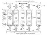
- FIG. 1depicts a high-level block diagram illustrating an arrangement of some of the physical components in a network data distribution system configured to operate according to an embodiment of the present invention.
- FIG. 2depicts a high-level flow diagram illustrating an example of an algorithm that might be performed by a network data distribution system according to embodiments of the present invention.
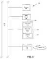
- FIG. 3is a block diagram of a computer system that may be used to implement a network data server or a network node in an embodiment of the present invention.
- Systems and methods implemented in accordance with the present inventionmay facilitate operation of a network database.
- a plurality of nodesare connected via two network connections.
- a first one of the networksis considered the existing network for communication between the nodes, and the second network is added for data only traffic between the nodes.
- This dual network connection configurationforms a network database, for example.
- the data (second) networkhandles data broadcasts from, for example, a node designated a data server, to all nodes in the network in a unidirectional (one-way) mode.
- broadcastis used herein to mean that data packets transmits along the network connection (e.g., bus) and may or may not have a specific destination node; nodes monitor the connection and acquire only the data packets that they have an interest in. This interest may be predetermined or specified by information in the data packet.
- the traffic back to the data serveralways travels on the first network.
- This configurationenables the data network to push data to nodes that have a need for the data and consume all of the available bandwidth on the data network.
- One-way trafficavoids the network congestion likely to exist on the first network, which handles bidirectional traffic between the nodes.
- the multi-network multi-node configurationfacilitates data replication between data servers (e.g., multiple nodes), thereby forming the backbone for a disaster recovery plan for data. Partitioning data transmission between two networks, one of which handling one-way traffic and the second handling two-way traffic, enables fast, reliable distribution of data among the network nodes. This way a data store may be distributed among the network nodes using known distribution and redundancy techniques, and in the event of a node failure or problem accessing a particular node, the data on that node may be recovered from a node designated by the particular distribution and redundancy technique employed as a backup for the problem node.
- usershave a higher confidence that the backup node contains a complete and accurate image of the data in the problem node because the data located in the node travels to the backup node, from the problem node or some other node in the network where it originates, using the higher transmission speed afforded by the data network.
- FIG. 1depicts a high-level block diagram illustrating an arrangement of some of the physical components in a network data distribution system configured to operate according to an embodiment of the present invention.
- a network data distribution system 100configured to operate according to a preferred embodiment of the present invention comprises a two-way data communication channel 140 , a one-way data communication channel 150 , which are both coupled to a network data server 110 and to each node in a plurality of network nodes (shown in FIG. 1 as nodes 160 A, 160 B, 160 C through 160 N) in the network.
- Two-way data communication channel 140is configured to carry actual data, as well as routing and flow control messages, in both directions, back and forth from one node to another node connected to the channel, including the network data server 110 .
- One-way data communication channel 150is configured to carry nothing but actual data (i.e., no protocol messages will be transmitted on the one-way channel), and only in one direction, namely away from network data server 110 and toward nodes 160 A through 160 N.
- Two-way data communication channel 140may be constructed, for example, using wire or cable (e.g., Ethernet cable), fiber optics, a phone line (e.g., over the PSTN), a cellular phone link, an RF link and other communications technology.
- One-way data communication channel 150may be constructed from the same kind of communications devices, but it may also be advantageous, depending on the application, to use cable television wire technology, since cable television wire technology is very mature and particularly well suited for transferring data in a single downstream direction to all other nodes in the network.
- Network data server 110includes a network interface adapter 115 , which provides a connection to the two-way data communication channel 140 via two-way communications link 113 .
- Network data server 110also includes a second network interface adapter 120 , which provides a one-way connection to one-way data communication channel 150 via one-way communications link 127 .
- Links 113 and 127may or may not be implemented using the same communication devices used to implement two-way data communication channel 140 and one-way data communication channel 150 .
- network data server 110also includes a data request processor 125 , which is configured to receive and process data requests generated by nodes 160 A through 160 N and transmitted to network data server 110 over two-way data communication channel 140 , communications link 113 and network interface adapter 115 .
- data request processor 125carries out the processing by accessing one or more data stores (designated 130 A, 130 B, 130 C . . . 130 N in FIG. 1 ), which are coupled to or incorporated within network data server 110 .
- network data server 110is configured (using high-speed caching technology, for example) to move and/or copy large volumes of data, under the control of data request processor 125 , from the actual data stores 130 A through 130 N (such as, for example, disk drives) to one-way data communication channel 150 at very high speeds.
- nodes 160 A through 160 Neach contain a network interface adapter (shown in FIG. 1 as 165 A through 165 N), which couples each node 160 A through 160 N to two-way data communication channel 140 via two-way communications links 162 A, 162 B, 162 C through 162 N, respectively.
- Each node 160 A through 160 Nalso contains a second network interface adapter (shown in FIG. 1 as 170 A through 170 N), which couple nodes 160 A through 160 N to one-way data communication channel 150 via one-way communications links 173 A, 173 B, 173 C through 173 N, respectively.
- Each node 160 A through 160 Nmay also include data processors (designated 180 A, 180 B, 180 C through 180 N in FIG.
- Each data requestmay comprise a request to receive, update, modify, delete or move data stored on data stores 130 A through 130 N, or some combination of two or more of these operations.
- Data modificationsmay take place on any of the nodes 160 A through 160 N.
- a node in the networklearns that a customer “A” has just made a $100 charge to his account. The information about the charge would flow to network data server 110 over the 2-way data channel 140 .
- node 160 Nis used to create a new monthly billing statement for customer A, it will retrieve the current data concerning customer A's account (i.e., the $100 charge, as well as the current balance) from network data server 110 over one-way channel 150 , so it can produce the correct bill.
- One-way communications links 173 A, 173 B, 173 C through 173 N, as well as network interface adapters 170 A through 170 N,are optimally configured to operate under the control of data processors 180 A, 180 B, 180 C through 180 N, to move data in only one direction, namely from one-way data communication channel 150 and into memory storage areas ( 185 A, 185 B, 185 C through 185 N), where the data may then be accessed by any applications running on those nodes.
- Data processors 180 A through 180 Nare also configured to identify and capture data traversing one-way data communication channel 150 , which is responsive to the generated data request and to ignore all data traversing one-way data communication channel 150 which is not responsive to a pending data request.
- FIG. 2depicts a high-level flow diagram illustrating an example of an algorithm that might be performed by a network data distribution system, such as the one described above with reference to FIG. 1 , according to embodiments of the present invention.
- network data server 110may be configured to continuously monitor two-way data communication channel 140 in order to determine whether a data request has been received (the test is shown at step 210 in FIG. 2 ).
- network data server 110also determines whether a confirmation associated with an earlier data request has been received.
- the systemcontinues to check the two-way channel (shown as the flow control loop consisting of steps 205 , 210 and 240 ) until either a new data request or a confirmation is received.
- the systemretrieves the requested data item from one or more data stores ( 130 A through 130 N in FIG. 1 ) attached to network data server 110 .
- the data retrievaloccurs very rapidly under the control of a data request processor (designated 125 in FIG. 1 ), which generates a response to the data request containing the requested data item (step 220 ).
- the network data serverbroadcasts the response to all of the nodes in the network over the one-way data communication channel.
- the systemthen sends a notification to the appropriate node over the two-way data communication channel, said notification indicating that the requested data is being, will be, or has been, broadcasted over the high-speed one-way data communication channel (see step 230 ).
- the systemresets a timeout counter, which determines when the system will re-broadcast the response.
- controlpasses back to step 205 , where the system again monitors the two-way data communication channel until a data request or confirmation is received (depicted as the control loop consisting of steps 205 , 210 and 240 ).
- the systemtests incoming data on the two-way data communication channel to determine whether a confirmation associated with an earlier-broadcasted response has been received.
- the confirmationserves as an indication to the network data server that the network node that generated a data request has received the response over the one-way data communication channel. If the answer is yes, the system returns to step 205 and continues to monitor the two-way data communication channel. If, on the other hand, the answer is no, the system first determines, at step 245 , whether the timeout has expired. If the timeout has expired, then control passes again to step 225 , where the response is re-broadcasted to all nodes on the network. If the timeout has not expired, then the system determines whether the data item has changed, step 250 .
- Such changemight occur, for example, when another program, another node or process, modifies or updates the data item, or when the retrieval of the item by the network data server requires a modification to the item. If the data item has been changed, then control passes again to step 220 , where a new response is generated and then, in step 225 , broadcasted over the one-way data communication channel. If, however, the data item has not changed, then control passes back to step 205 , where the system continues to monitor the two-way data communication channel until the timeout does expire, a new data request or confirmation is received, or the data item is changed.
- FIG. 3is a block diagram of a computer system that may be used to implement a network data server or a network node in an embodiment of the present invention.
- the computer system 302includes one or more processors, such as a processor 304 .
- the processor 304is connected to a communication bus 306 .
- Various software embodimentsare described in terms of this exemplary computer system. After reading this description, it will become apparent to a person skilled in the relevant art how to implement the invention using other computer systems and/or computer architectures.
- the computer system 302also includes a main memory 308 , preferably random access memory (RAM), and can also include a secondary memory 310 .
- the secondary memory 310can include, for example, a hard disk drive 312 and/or a removable storage drive 314 , representing a floppy disk drive, a magnetic tape drive, an optical disk drive, etc.
- the removable storage drive 314reads from and/or writes to a removable storage unit 318 in a well-known manner.
- the removable storage unit 318represents a floppy disk, magnetic tape, optical disk, etc. which is read by and written to by the removable storage drive 314 .
- the removable storage unit 318includes a computer usable storage medium having stored therein computer software and/or data.
- the secondary memory 310may include other similar means for allowing computer programs or other instructions to be loaded into the computer system 302 .
- Such meanscan include, for example, a removable storage unit 322 and an interface 320 .
- Examples of suchcan include a program cartridge and cartridge interface (such as that found in video game devices), a removable memory chip (such as an EPROM, or PROM) and associated socket, and other removable storage units 322 and interfaces 320 , which allow software and data to be transferred from the removable storage unit 322 to the computer system 302 .
- the computer system 302can also include a communications interface 324 .
- the communications interface 324allows software and data to be transferred between the computer system 302 and external devices. Examples of the communications interface 324 can include a modem, a network interface adapter (such as an Ethernet card), a communications port, a PCMCIA slot and card, etc.
- Software and data transferred via the communications interface 324are in the form of signals 326 that can be electronic, electromagnetic, optical or other signals capable of being received by the communications interface 324 .
- Signals 326are provided to communications interface via a channel 328 , which can be implemented using wire or cable, fiber optics, a phone line, a cellular phone link, an RF link and other communications channels.
- computer-readable storage mediumis used to generally refer to media such as the removable storage device 318 , a hard disk installed in hard disk drive 312 , and signals 326 . These media are means for providing software and operating instructions to the computer system 302 .
- Computer programsare stored in the main memory 308 and/or the secondary memory 310 . Computer programs can also be received via the communications interface 324 . Such computer programs, when executed, enable the computer system 302 (e.g., through processor 304 ) to implement the systems and methods that include the present invention.
- the softwaremay be stored in a computer-readable storage medium and loaded into the computer system 302 using the removable storage drive 314 , the hard drive 312 or the communications interface 324 .
- the control logicwhen executed by the processor 304 , causes the processor 304 to perform the functions of the invention as described herein.
- the inventionis implemented primarily in hardware using, for example, hardware components such as application specific integrated circuits (ASICs).
- ASICsapplication specific integrated circuits
- Implementation of a hardware state machine that implements the embodiments described hereinwill be apparent to persons skilled in the relevant art(s).
- the inventionis implemented using a combination of both hardware and software.
Landscapes
- Engineering & Computer Science (AREA)
- Computer Security & Cryptography (AREA)
- Computer Networks & Wireless Communication (AREA)
- Signal Processing (AREA)
- Data Exchanges In Wide-Area Networks (AREA)
Abstract
Description
Claims (17)
Priority Applications (3)
| Application Number | Priority Date | Filing Date | Title |
|---|---|---|---|
| US11/122,602US8041832B2 (en) | 2005-05-05 | 2005-05-05 | Network data distribution system and method |
| PCT/US2006/017409WO2006121858A2 (en) | 2005-05-05 | 2006-05-05 | Network data distribution system and method |
| EP06770036AEP1877924A4 (en) | 2005-05-05 | 2006-05-05 | Network data distribution system and method |
Applications Claiming Priority (1)
| Application Number | Priority Date | Filing Date | Title |
|---|---|---|---|
| US11/122,602US8041832B2 (en) | 2005-05-05 | 2005-05-05 | Network data distribution system and method |
Publications (2)
| Publication Number | Publication Date |
|---|---|
| US20060271617A1 US20060271617A1 (en) | 2006-11-30 |
| US8041832B2true US8041832B2 (en) | 2011-10-18 |
Family
ID=37397128
Family Applications (1)
| Application Number | Title | Priority Date | Filing Date |
|---|---|---|---|
| US11/122,602Expired - Fee RelatedUS8041832B2 (en) | 2005-05-05 | 2005-05-05 | Network data distribution system and method |
Country Status (3)
| Country | Link |
|---|---|
| US (1) | US8041832B2 (en) |
| EP (1) | EP1877924A4 (en) |
| WO (1) | WO2006121858A2 (en) |
Cited By (9)
| Publication number | Priority date | Publication date | Assignee | Title |
|---|---|---|---|---|
| US20090113500A1 (en)* | 2007-10-24 | 2009-04-30 | Gita Technologies Ltd. | Secure implementation of network-based sensors |
| US20090319773A1 (en)* | 2006-08-29 | 2009-12-24 | Waterfall Security Solutions Ltd | Encryption-based control of network traffic |
| US20090328183A1 (en)* | 2006-06-27 | 2009-12-31 | Waterfall Solutions Ltd. | One way secure link |
| US20100275039A1 (en)* | 2007-01-16 | 2010-10-28 | Waterfall Security Solutions Ltd | Secure archive |
| US9268957B2 (en) | 2006-12-12 | 2016-02-23 | Waterfall Security Solutions Ltd. | Encryption-and decryption-enabled interfaces |
| US9369446B2 (en) | 2014-10-19 | 2016-06-14 | Waterfall Security Solutions Ltd. | Secure remote desktop |
| US9419975B2 (en) | 2013-04-22 | 2016-08-16 | Waterfall Security Solutions Ltd. | Bi-directional communication over a one-way link |
| US9635037B2 (en) | 2012-09-06 | 2017-04-25 | Waterfall Security Solutions Ltd. | Remote control of secure installations |
| US10356226B2 (en) | 2016-02-14 | 2019-07-16 | Waaterfall Security Solutions Ltd. | Secure connection with protected facilities |
Families Citing this family (13)
| Publication number | Priority date | Publication date | Assignee | Title |
|---|---|---|---|---|
| US8566922B2 (en) | 2011-05-25 | 2013-10-22 | Barry W. Hargis | System for isolating a secured data communication network |
| US12276420B2 (en) | 2016-02-03 | 2025-04-15 | Strong Force Iot Portfolio 2016, Llc | Industrial internet of things smart heating systems and methods that produce and use hydrogen fuel |
| KR20230157525A (en) | 2016-05-09 | 2023-11-16 | 스트롱 포스 아이오티 포트폴리오 2016, 엘엘씨 | Methods and systems for the industrial internet of things |
| US11774944B2 (en) | 2016-05-09 | 2023-10-03 | Strong Force Iot Portfolio 2016, Llc | Methods and systems for the industrial internet of things |
| US11327475B2 (en) | 2016-05-09 | 2022-05-10 | Strong Force Iot Portfolio 2016, Llc | Methods and systems for intelligent collection and analysis of vehicle data |
| US10983507B2 (en) | 2016-05-09 | 2021-04-20 | Strong Force Iot Portfolio 2016, Llc | Method for data collection and frequency analysis with self-organization functionality |
| US11507064B2 (en) | 2016-05-09 | 2022-11-22 | Strong Force Iot Portfolio 2016, Llc | Methods and systems for industrial internet of things data collection in downstream oil and gas environment |
| US11237546B2 (en) | 2016-06-15 | 2022-02-01 | Strong Force loT Portfolio 2016, LLC | Method and system of modifying a data collection trajectory for vehicles |
| US11442445B2 (en) | 2017-08-02 | 2022-09-13 | Strong Force Iot Portfolio 2016, Llc | Data collection systems and methods with alternate routing of input channels |
| JP7595319B2 (en) | 2017-08-02 | 2024-12-06 | ストロング フォース アイオーティ ポートフォリオ 2016,エルエルシー | Method and system for detection in an industrial internet of things data collection environment using large data sets |
| US20200133254A1 (en) | 2018-05-07 | 2020-04-30 | Strong Force Iot Portfolio 2016, Llc | Methods and systems for data collection, learning, and streaming of machine signals for part identification and operating characteristics determination using the industrial internet of things |
| CA3126601A1 (en) | 2019-01-13 | 2020-07-16 | Strong Force Iot Portfolio 2016, Llc | Methods, systems, kits and apparatuses for monitoring and managing industrial settings |
| CN110175069B (en)* | 2019-05-20 | 2023-11-14 | 广州南洋理工职业学院 | Distributed transaction processing system and method based on broadcast channel |
Citations (10)
| Publication number | Priority date | Publication date | Assignee | Title |
|---|---|---|---|---|
| US5790753A (en) | 1996-01-22 | 1998-08-04 | Digital Equipment Corporation | System for downloading computer software programs |
| US6091757A (en)* | 1998-12-03 | 2000-07-18 | Motorola, Inc. | Data transmission within a spread-spectrum communication system |
| US6144402A (en)* | 1997-07-08 | 2000-11-07 | Microtune, Inc. | Internet transaction acceleration |
| US6317831B1 (en) | 1998-09-21 | 2001-11-13 | Openwave Systems Inc. | Method and apparatus for establishing a secure connection over a one-way data path |
| US20030018719A1 (en)* | 2000-12-27 | 2003-01-23 | Ruths Derek Augustus Samuel | Data-centric collaborative computing platform |
| US6543005B1 (en) | 1999-10-27 | 2003-04-01 | Oracle Corporation | Transmitting data reliably and efficiently |
| WO2003041397A1 (en) | 2001-11-08 | 2003-05-15 | Thomson Licensing S.A. | Module and process for inter-user communication |
| US20030137536A1 (en) | 2001-11-30 | 2003-07-24 | Hugh Harlan M. | Method and apparatus for communicating changes from and to a shared associative database using one-way communications techniques |
| US6963993B1 (en)* | 2000-09-28 | 2005-11-08 | The United States Of America As Represented By The Administrator Of The National Aeronautics And Space Administration | Fail-over file transfer process |
| US20050273822A1 (en)* | 2004-01-20 | 2005-12-08 | Snell William L | Video-on-demand satellite system |
- 2005
- 2005-05-05USUS11/122,602patent/US8041832B2/ennot_activeExpired - Fee Related
- 2006
- 2006-05-05WOPCT/US2006/017409patent/WO2006121858A2/enactiveApplication Filing
- 2006-05-05EPEP06770036Apatent/EP1877924A4/ennot_activeWithdrawn
Patent Citations (10)
| Publication number | Priority date | Publication date | Assignee | Title |
|---|---|---|---|---|
| US5790753A (en) | 1996-01-22 | 1998-08-04 | Digital Equipment Corporation | System for downloading computer software programs |
| US6144402A (en)* | 1997-07-08 | 2000-11-07 | Microtune, Inc. | Internet transaction acceleration |
| US6317831B1 (en) | 1998-09-21 | 2001-11-13 | Openwave Systems Inc. | Method and apparatus for establishing a secure connection over a one-way data path |
| US6091757A (en)* | 1998-12-03 | 2000-07-18 | Motorola, Inc. | Data transmission within a spread-spectrum communication system |
| US6543005B1 (en) | 1999-10-27 | 2003-04-01 | Oracle Corporation | Transmitting data reliably and efficiently |
| US6963993B1 (en)* | 2000-09-28 | 2005-11-08 | The United States Of America As Represented By The Administrator Of The National Aeronautics And Space Administration | Fail-over file transfer process |
| US20030018719A1 (en)* | 2000-12-27 | 2003-01-23 | Ruths Derek Augustus Samuel | Data-centric collaborative computing platform |
| WO2003041397A1 (en) | 2001-11-08 | 2003-05-15 | Thomson Licensing S.A. | Module and process for inter-user communication |
| US20030137536A1 (en) | 2001-11-30 | 2003-07-24 | Hugh Harlan M. | Method and apparatus for communicating changes from and to a shared associative database using one-way communications techniques |
| US20050273822A1 (en)* | 2004-01-20 | 2005-12-08 | Snell William L | Video-on-demand satellite system |
Non-Patent Citations (2)
| Title |
|---|
| Extended European Search Report issued on Mar. 9, 2011 in counterpart European Application No. 06770036.9. |
| RFC 793, "Transmission Control Protocol Darpa Internet Program Protocol Specification", University of Southern California. pp. 1-10.* |
Cited By (14)
| Publication number | Priority date | Publication date | Assignee | Title |
|---|---|---|---|---|
| US20090328183A1 (en)* | 2006-06-27 | 2009-12-31 | Waterfall Solutions Ltd. | One way secure link |
| US9762536B2 (en)* | 2006-06-27 | 2017-09-12 | Waterfall Security Solutions Ltd. | One way secure link |
| US8635441B2 (en) | 2006-08-29 | 2014-01-21 | Waterfall Security Solutions Ltd. | Encryption-based control of network traffic |
| US20090319773A1 (en)* | 2006-08-29 | 2009-12-24 | Waterfall Security Solutions Ltd | Encryption-based control of network traffic |
| US9268957B2 (en) | 2006-12-12 | 2016-02-23 | Waterfall Security Solutions Ltd. | Encryption-and decryption-enabled interfaces |
| US8756436B2 (en) | 2007-01-16 | 2014-06-17 | Waterfall Security Solutions Ltd. | Secure archive |
| US20100275039A1 (en)* | 2007-01-16 | 2010-10-28 | Waterfall Security Solutions Ltd | Secure archive |
| US20090113500A1 (en)* | 2007-10-24 | 2009-04-30 | Gita Technologies Ltd. | Secure implementation of network-based sensors |
| US8793302B2 (en) | 2007-10-24 | 2014-07-29 | Waterfall Security Solutions Ltd. | Secure implementation of network-based sensors |
| US8223205B2 (en) | 2007-10-24 | 2012-07-17 | Waterfall Solutions Ltd. | Secure implementation of network-based sensors |
| US9635037B2 (en) | 2012-09-06 | 2017-04-25 | Waterfall Security Solutions Ltd. | Remote control of secure installations |
| US9419975B2 (en) | 2013-04-22 | 2016-08-16 | Waterfall Security Solutions Ltd. | Bi-directional communication over a one-way link |
| US9369446B2 (en) | 2014-10-19 | 2016-06-14 | Waterfall Security Solutions Ltd. | Secure remote desktop |
| US10356226B2 (en) | 2016-02-14 | 2019-07-16 | Waaterfall Security Solutions Ltd. | Secure connection with protected facilities |
Also Published As
| Publication number | Publication date |
|---|---|
| EP1877924A2 (en) | 2008-01-16 |
| WO2006121858A2 (en) | 2006-11-16 |
| WO2006121858A3 (en) | 2007-10-11 |
| US20060271617A1 (en) | 2006-11-30 |
| EP1877924A4 (en) | 2011-04-06 |
Similar Documents
| Publication | Publication Date | Title |
|---|---|---|
| US8041832B2 (en) | Network data distribution system and method | |
| CA1257399A (en) | Local area network for digital data processing system | |
| US6393023B1 (en) | System and method for acknowledging receipt of messages within a packet based communication network | |
| US4975904A (en) | Local area network for digital data processing system including timer-regulated message transfer arrangement | |
| US20100138511A1 (en) | Queue-based adaptive chunk scheduling for peer-to peer live streaming | |
| US6678244B1 (en) | Congestion management system and method | |
| US10079782B2 (en) | Facilitating communication of data packets using credit-based flow control | |
| US20080028090A1 (en) | System for managing messages transmitted in an on-chip interconnect network | |
| US10009396B2 (en) | Queue-based adaptive chunk scheduling for peer-to-peer live streaming | |
| EP4618503A1 (en) | Data transmission processing method and device, storage medium, and electronic device | |
| US7804775B2 (en) | Apparatus and computer program for identifying selected applications utilizing a single existing available bit in frame headers | |
| US20030227874A1 (en) | Intelligent flow control management to extend fibre channel link full performance range | |
| TWI411264B (en) | Non-block network system and packet arbitration method thereof | |
| JP5720794B2 (en) | Distribution network, server and distribution method | |
| US6657961B1 (en) | System and method for enhanced end station to end station data flow control | |
| JPH11239163A (en) | Inter-LAN flow control method and switch | |
| JP2901947B2 (en) | Video server using ATM backbone network | |
| JP2000101642A (en) | Stream distribution method and system | |
| JP7456603B2 (en) | switch device | |
| CN102137454B (en) | Content storage method and device in service overlay network | |
| JP3352038B2 (en) | Data communication system and communication method | |
| CN118200265B (en) | Switch cache management method for distinguishing monitoring and exchanging data | |
| CA2492577C (en) | Method and apparatus for usage estimation and prediction in two-way communications networks | |
| JP2785147B2 (en) | Restriction method for each route | |
| JP2002190826A (en) | Packet transfer method and network system |
Legal Events
| Date | Code | Title | Description |
|---|---|---|---|
| ZAAA | Notice of allowance and fees due | Free format text:ORIGINAL CODE: NOA | |
| ZAAB | Notice of allowance mailed | Free format text:ORIGINAL CODE: MN/=. | |
| AS | Assignment | Owner name:VERIZON SERVICES CORP., VIRGINIA Free format text:ASSIGNMENT OF ASSIGNORS INTEREST;ASSIGNORS:HUGHES, GEORGE LOUIS, JR.;REDING, CRAIG;SIGNING DATES FROM 20110913 TO 20110914;REEL/FRAME:026931/0635 | |
| STCF | Information on status: patent grant | Free format text:PATENTED CASE | |
| AS | Assignment | Owner name:VERIZON PATENT AND LICENSING INC., NEW JERSEY Free format text:ASSIGNMENT OF ASSIGNORS INTEREST;ASSIGNOR:VERIZON SERVICES CORP.;REEL/FRAME:033428/0605 Effective date:20140409 | |
| FPAY | Fee payment | Year of fee payment:4 | |
| MAFP | Maintenance fee payment | Free format text:PAYMENT OF MAINTENANCE FEE, 8TH YEAR, LARGE ENTITY (ORIGINAL EVENT CODE: M1552); ENTITY STATUS OF PATENT OWNER: LARGE ENTITY Year of fee payment:8 | |
| FEPP | Fee payment procedure | Free format text:MAINTENANCE FEE REMINDER MAILED (ORIGINAL EVENT CODE: REM.); ENTITY STATUS OF PATENT OWNER: LARGE ENTITY | |
| LAPS | Lapse for failure to pay maintenance fees | Free format text:PATENT EXPIRED FOR FAILURE TO PAY MAINTENANCE FEES (ORIGINAL EVENT CODE: EXP.); ENTITY STATUS OF PATENT OWNER: LARGE ENTITY | |
| STCH | Information on status: patent discontinuation | Free format text:PATENT EXPIRED DUE TO NONPAYMENT OF MAINTENANCE FEES UNDER 37 CFR 1.362 | |
| FP | Lapsed due to failure to pay maintenance fee | Effective date:20231018 |