US8041335B2 - Method and apparatus for routing of emergency services for unauthorized user equipment in a home Node B system - Google Patents
Method and apparatus for routing of emergency services for unauthorized user equipment in a home Node B systemDownload PDFInfo
- Publication number
- US8041335B2 US8041335B2US12/426,211US42621109AUS8041335B2US 8041335 B2US8041335 B2US 8041335B2US 42621109 AUS42621109 AUS 42621109AUS 8041335 B2US8041335 B2US 8041335B2
- Authority
- US
- United States
- Prior art keywords
- hnb
- message
- network
- ranap
- user equipment
- Prior art date
- Legal status (The legal status is an assumption and is not a legal conclusion. Google has not performed a legal analysis and makes no representation as to the accuracy of the status listed.)
- Active, expires
Links
Images


Classifications
- H—ELECTRICITY
- H04—ELECTRIC COMMUNICATION TECHNIQUE
- H04W—WIRELESS COMMUNICATION NETWORKS
- H04W92/00—Interfaces specially adapted for wireless communication networks
- H04W92/04—Interfaces between hierarchically different network devices
- H04W92/12—Interfaces between hierarchically different network devices between access points and access point controllers
- H—ELECTRICITY
- H04—ELECTRIC COMMUNICATION TECHNIQUE
- H04L—TRANSMISSION OF DIGITAL INFORMATION, e.g. TELEGRAPHIC COMMUNICATION
- H04L63/00—Network architectures or network communication protocols for network security
- H04L63/10—Network architectures or network communication protocols for network security for controlling access to devices or network resources
- H04L63/104—Grouping of entities
- H—ELECTRICITY
- H04—ELECTRIC COMMUNICATION TECHNIQUE
- H04W—WIRELESS COMMUNICATION NETWORKS
- H04W12/00—Security arrangements; Authentication; Protecting privacy or anonymity
- H04W12/08—Access security
- H—ELECTRICITY
- H04—ELECTRIC COMMUNICATION TECHNIQUE
- H04W—WIRELESS COMMUNICATION NETWORKS
- H04W76/00—Connection management
- H04W76/10—Connection setup
- H04W76/12—Setup of transport tunnels
- H—ELECTRICITY
- H04—ELECTRIC COMMUNICATION TECHNIQUE
- H04L—TRANSMISSION OF DIGITAL INFORMATION, e.g. TELEGRAPHIC COMMUNICATION
- H04L12/00—Data switching networks
- H04L12/54—Store-and-forward switching systems
- H04L12/56—Packet switching systems
- H04L12/5601—Transfer mode dependent, e.g. ATM
- H04L2012/5603—Access techniques
- H04L2012/5604—Medium of transmission, e.g. fibre, cable, radio
- H04L2012/5607—Radio
- H—ELECTRICITY
- H04—ELECTRIC COMMUNICATION TECHNIQUE
- H04L—TRANSMISSION OF DIGITAL INFORMATION, e.g. TELEGRAPHIC COMMUNICATION
- H04L12/00—Data switching networks
- H04L12/54—Store-and-forward switching systems
- H04L12/56—Packet switching systems
- H04L12/5601—Transfer mode dependent, e.g. ATM
- H04L2012/5638—Services, e.g. multimedia, GOS, QOS
- H04L2012/5646—Cell characteristics, e.g. loss, delay, jitter, sequence integrity
- H04L2012/5652—Cell construction, e.g. including header, packetisation, depacketisation, assembly, reassembly
- H04L2012/5653—Cell construction, e.g. including header, packetisation, depacketisation, assembly, reassembly using the ATM adaptation layer [AAL]
- H04L2012/5656—Cell construction, e.g. including header, packetisation, depacketisation, assembly, reassembly using the ATM adaptation layer [AAL] using the AAL2
- H—ELECTRICITY
- H04—ELECTRIC COMMUNICATION TECHNIQUE
- H04L—TRANSMISSION OF DIGITAL INFORMATION, e.g. TELEGRAPHIC COMMUNICATION
- H04L51/00—User-to-user messaging in packet-switching networks, transmitted according to store-and-forward or real-time protocols, e.g. e-mail
- H04L51/21—Monitoring or handling of messages
- H04L51/222—Monitoring or handling of messages using geographical location information, e.g. messages transmitted or received in proximity of a certain spot or area
- H—ELECTRICITY
- H04—ELECTRIC COMMUNICATION TECHNIQUE
- H04W—WIRELESS COMMUNICATION NETWORKS
- H04W12/00—Security arrangements; Authentication; Protecting privacy or anonymity
- H04W12/60—Context-dependent security
- H04W12/69—Identity-dependent
- H04W12/72—Subscriber identity
- H—ELECTRICITY
- H04—ELECTRIC COMMUNICATION TECHNIQUE
- H04W—WIRELESS COMMUNICATION NETWORKS
- H04W12/00—Security arrangements; Authentication; Protecting privacy or anonymity
- H04W12/60—Context-dependent security
- H04W12/69—Identity-dependent
- H04W12/73—Access point logical identity
- H—ELECTRICITY
- H04—ELECTRIC COMMUNICATION TECHNIQUE
- H04W—WIRELESS COMMUNICATION NETWORKS
- H04W36/00—Hand-off or reselection arrangements
- H04W36/0005—Control or signalling for completing the hand-off
- H04W36/0055—Transmission or use of information for re-establishing the radio link
- H04W36/0066—Transmission or use of information for re-establishing the radio link of control information between different types of networks in order to establish a new radio link in the target network
- H—ELECTRICITY
- H04—ELECTRIC COMMUNICATION TECHNIQUE
- H04W—WIRELESS COMMUNICATION NETWORKS
- H04W48/00—Access restriction; Network selection; Access point selection
- H04W48/18—Selecting a network or a communication service
- H—ELECTRICITY
- H04—ELECTRIC COMMUNICATION TECHNIQUE
- H04W—WIRELESS COMMUNICATION NETWORKS
- H04W60/00—Affiliation to network, e.g. registration; Terminating affiliation with the network, e.g. de-registration
- H04W60/04—Affiliation to network, e.g. registration; Terminating affiliation with the network, e.g. de-registration using triggered events
- H—ELECTRICITY
- H04—ELECTRIC COMMUNICATION TECHNIQUE
- H04W—WIRELESS COMMUNICATION NETWORKS
- H04W76/00—Connection management
- H04W76/30—Connection release
- H04W76/32—Release of transport tunnels
- H—ELECTRICITY
- H04—ELECTRIC COMMUNICATION TECHNIQUE
- H04W—WIRELESS COMMUNICATION NETWORKS
- H04W8/00—Network data management
- H04W8/02—Processing of mobility data, e.g. registration information at HLR [Home Location Register] or VLR [Visitor Location Register]; Transfer of mobility data, e.g. between HLR, VLR or external networks
- H04W8/08—Mobility data transfer
- H04W8/16—Mobility data transfer selectively restricting mobility data tracking
- H—ELECTRICITY
- H04—ELECTRIC COMMUNICATION TECHNIQUE
- H04W—WIRELESS COMMUNICATION NETWORKS
- H04W84/00—Network topologies
- H04W84/02—Hierarchically pre-organised networks, e.g. paging networks, cellular networks, WLAN [Wireless Local Area Network] or WLL [Wireless Local Loop]
- H04W84/04—Large scale networks; Deep hierarchical networks
- H04W84/042—Public Land Mobile systems, e.g. cellular systems
- H04W84/045—Public Land Mobile systems, e.g. cellular systems using private Base Stations, e.g. femto Base Stations, home Node B
Definitions
- Provisional Application 61/101,148entitled, “Support for Closer Subscriber Group (CSG) in Femtocell System”, filed Sep. 29, 2008.
- the contents of Provisional Applications 61/046,401, 61/055,961, 61/058,912, 61/080,227, and 61/101,148are hereby incorporated by reference.
- the inventionrelates to telecommunication. More particularly, this invention relates to a Home Node-B system architecture.
- Licensed wireless systemsprovide mobile wireless communications to individuals using wireless transceivers.
- Licensed wireless systemsrefer to public cellular telephone systems and/or Personal Communication Services (PCS) telephone systems.
- Wireless transceiversalso referred to as user equipment (UE), include cellular telephones, PCS telephones, wireless-enabled personal digital assistants, wireless modems, and the like.
- Licensed wireless systemsutilize wireless signal frequencies that are licensed from governments. Large fees are paid for access to these frequencies.
- Expensive base station (BS) equipmentis used to support communications on licensed frequencies.
- Base stationsare typically installed approximately a mile apart from one another (e.g., cellular towers in a cellular network).
- UMTSUniversal Mobile Telecommunications System
- these base stationsare system provider controlled and include Node-Bs which are high power and long range radio frequency transmitters and receivers used to directly connect with the user equipment.
- the wireless transport mechanisms and frequencies employed by typical licensed wireless systemslimit both data transfer rates and range.
- Licensed wireless systemscontinually upgrade their networks and equipment in an effort to deliver greater data transfer rates and range.
- the licensed wireless system providersincur substantial costs from licensing additional bandwidth spectrum to upgrading the existing radio network equipment or core network equipment.
- the licensed wireless system providerspass down the costs to the user through the licensed wireless service fees.
- Usersalso incur equipment costs with each iterative upgrade of the licensed wireless network as new user equipment is needed to take advantage of the new services or improved services of the upgraded network.
- Landline (wired) connectionsare extensively deployed and generally perform at a lower cost with higher quality voice and higher speed data services than the licensed wireless systems.
- the problem with landline connectionsis that they constrain the mobility of a user.
- Traditionallya physical connection to the landline was required.
- Unlicensed Mobile Accessemerged as one solution to lower costs associated with the licensed wireless systems while maintaining user wireless mobility and taking advantage of the higher quality voice and higher speed data services of the landline connections.
- UMAallowed users the ability to seamlessly and wirelessly roam in and out of licensed wireless systems and unlicensed wireless systems where the unlicensed wireless systems facilitate mobile access to the landline-based networks.
- Such unlicensed wireless systemssupport wireless communication based on the IEEE 802.11a, b or g standards (WiFi), or the Bluetooth® standard.
- WiFiIEEE 802.11a, b or g standards
- Bluetooth®Bluetooth® standard.
- the mobility range associated with such unlicensed wireless systemsis typically on the order of 100 meters or less.
- a typical unlicensed wireless communication systemincludes a base station comprising a wireless access point (AP) with a physical connection (e.g., coaxial, twisted pair, or optical cable) to a landline-based network.
- the APhas a RF transceiver to facilitate communication with a wireless handset that is operative within a modest distance of the AP, wherein the data transport rates supported by the WiFi and Bluetooth® standards are much higher than those supported by the aforementioned licensed wireless systems.
- UMAallowed users to purchase ordinary off-the-shelf access points in order to deploy a UMA service region that allowed for access to UMA service. In this manner, UMA was able to provide higher quality services at a lower cost than the licensed wireless systems. However, other UMA associated costs remained an obstacle to the large scale adoption of UMA.
- HNBsHome Node Bs
- the HNBsemploy similar techniques as unlicensed access points such as the support of lower transmission power and range, integrated design, and use of regular landlines to communicate with the mobile operators' network to be cost and performance competitive with UMA.
- the use of regular landlinesrequired the HNBs to adopt proprietary messaging and signaling standards that were different than those used by the licensed wireless systems for the expensive Base Stations.
- Some embodimentsprovide methods and systems for integrating a first communication system with a core network of a second communication system that has a licensed wireless radio access network.
- the first communication systemincludes one or more user hosted access points that operate using short range licensed wireless frequencies in order to establish service regions of the first communication system and a network controller for communicatively coupling the service regions associated with the access points to the core network.
- the first communication system of some embodimentsincludes a Home Node-B (HNB) Access Network (HNB-AN) where the access points are Home Node-Bs and the network controller is a HNB Gateway (HNB-GW).
- the licensed wireless radio access network of the second communication system of some embodimentsincludes a Universal Mobile Telecommunications System (UMTS) Terrestrial Radio Access Network (UTRAN) and the core network of the second communication system includes a core network of the UMTS.
- UMTSUniversal Mobile Telecommunications System
- UTRANUniversal Mobile Telecommunications System
- the network controller of some embodimentsseamlessly integrates each of the short range licensed wireless service regions with the core network.
- the network controllerseamlessly integrates with the core network by using existing Iu interfaces of the core network to communicatively couple each of the service regions to the core network.
- the network controller of some embodimentsuses standardized messaging and protocols to communicate with the core network while utilizing HNB-AN messaging and protocols to communicate with each of the service regions.
- the network controller of some embodimentsreduces deployment costs of the HNB-AN within the UMTS core network.
- deployment of the network controller of some embodimentsrequires no change to the UMTS core network while still providing HNB wireless service that combines the mobility of licensed wireless networks with the quality and speed of landline/broadband services.
- the network controllerstake on some of the functionality of a traditional Radio Network Controller (RNC).
- RNCRadio Network Controller
- the access points of some embodimentsseamlessly integrate with existing user equipment (UE) of the licensed wireless radio access networks of the second communication system.
- UEuser equipment
- the access pointsreduce deployment costs of the HNB-AN, as users are able to utilize existing UE in order to wirelessly communicate through either the first communication system or the second communication system where the first communication system combines the wireless mobility afforded by the licensed wireless radio access network of the second communication system with the speed and quality of service afforded by landline/broadband services.
- the access pointsare functionally equivalent to a Node-B of the UTRAN while having the flexibility and lower deployment costs associated with an ad-hoc and user hosted service region.
- the access pointstake on some the functionality of a traditional Radio Network Controller (RNC).
- RNCRadio Network Controller
- Some embodimentsdefine multi-layered protocol stacks for implementing management functionality within the access points and the network controller of the first communication system.
- the protocol stacksinclude a management layer that performs functionality of the HNB Application Part (HNBAP) protocol.
- HNBAPHNB Application Part
- the protocol stacks of some embodimentsimplement management functionality that includes a registration procedure for registering a particular access point with the network controller.
- the protocol stacksenable a registration procedure that allows a service region associated with a particular access point to access services of the core network through the network controller.
- Additional management functionality implemented by the protocol stacks of some embodimentsinclude discovery procedures for identifying a network controller with which the particular access point is to register.
- the protocol stacksinclude a Radio Access Network Application Part (RANAP) user adaptation (RUA) layer that enables a method for transparently passing RANAP messages between the access points and the network controller over a reliable transport connection.
- the methodreceives a RANAP message and encapsulates the message with a RUA header.
- the methodthen passes the encapsulated message to a receiving endpoint within the first communication system. In this manner, the RANAP message is passed from a first endpoint of the first communication system to a second endpoint of the first communication system.
- RANAPRadio Access Network Application Part
- RUARadio Access Network Application Part
- the network controllerdecodes and processes only the RUA header before relaying the RANAP message to the core network operating within a service region of the first communication system.
- an access pointperforms the RANAP encapsulation and the receiving endpoint is a network controller.
- the network controllerperforms the RANAP encapsulation and the receiving endpoint is an access point.
- the receiving endpointneed only decode and process the RUA header.
- RANAPis only used to communicate with core network. The communication with UE (e.g.
- the HNBuses the RRC protocol as per 3GPP 25.331 specifications, “Radio Resource Control (RRC) Protocol Specification”, the contents of which are herein incorporated by reference, hereinafter referred to as TS 25.331.
- the HNB on the receiving endprocesses the RUA as well as the entire RANAP message.
- the content of the RANAP messagesare extracted by the HNB and converted to appropriate RRC messages.
- Some embodimentsdefine messaging formats to be used in conjunction with the various protocol stacks. Some embodiments provide a message that when sent from a particular access point to the network controller explicitly indicates the start of a communication session between the particular access point and the network controller. In some embodiments, the contents of the message are used to route the establishment of a signaling connection from the network controller to a core network node within a core network domain identified by the message.
- Some embodimentsprovide a computer readable storage medium of an access point that stores a computer program.
- the computer programincludes instructions that are executable by one or more processors.
- the computer programincludes a set of instruction for generating a message to send to the network controller to explicitly indicate start of a communication session with the network controller.
- the messageincludes a Radio Access Network Application Part (RANAP) message for establishing a signaling connection with the network controller.
- the computer programalso includes a set of instructions for passing a set of RANAP messages to the core network through the network controller after establishing the signaling connection.
- the set of RANAP messagesfacilitates communications between the particular access point and the core network.
- RANAPRadio Access Network Application Part
- Some embodimentsprovide a computer readable storage medium of a particular access point that stores a computer program.
- the computer programincludes instructions that are executable by one or more processors.
- the computer programincludes a set of instruction for receiving a message to explicitly indicate start of a communication session with a particular access point.
- the messageincludes a Radio Access Network Application Part (RANAP) message that is encapsulated with a header of the second network.
- RANAPRadio Access Network Application Part
- the messageis used for establishing a signaling connection with the particular access point.
- the computer programalso includes a set of instructions for analyzing the message header to identify a destination in the core network to receive the message.
- the computer programfurther includes a set of instructions for forwarding the message without the header to the destination in the core network to establish the signaling connection
- Some embodimentsfurther provide messages for directly transferring data downstream from the core network through the first communication system to a UE operating within a particular service region. Some embodiments provide messages for directly transferring data upstream from a UE in a particular service region through the first communication system to the core network. Directly transferring data involves routing a RANAP message through the network controller and an access point where the contents of the RANAP message are not processed by the network controller. In some embodiments, the network controller may process and modify the content of some of the RANAP message (for example, transport network switching that is converting ATM transport from/to the core network into the appropriate IP transport over the HNB-AN).
- Some embodimentsprovide a computer-readable medium that is encoded with a data storage structure.
- the data storage structurefor passing a Radio Access Network Application Part (RANAP) message within a first communication system that includes several user hosted access points for establishing service regions of the first communication system by using short range licensed wireless frequencies and a network controller that can communicatively couple user equipment operating in the service regions to a core network of a second communication system that also includes a licensed wireless radio access network.
- the data storage structurehas a header that includes a core network domain identity to identify at least one of a core network domain from which the RANAP message originated and a core network domain for which the RANAP message is to be sent.
- the headeralso includes a context identifier to uniquely identify a particular user equipment operating within a particular service region of the second communication system.
- the data storage structurealso includes payload data that include the RANAP message.
- the registration procedure of some embodimentsspecifies a method for registering UEs with the first communication system.
- the methodfrom an access point coupled to a UE sends a registration request message to the network controller on behalf of the UE.
- the methodreceives a registration accept message when the UE is authorized to access services of the first communication system through the particular access point.
- some embodimentsinclude a uniquely assigned context identifier that identifies the UE while the UE is connected for service at the particular access point. All subsequent messages will include the assigned context identifier to identify the UE.
- the registration procedure of some embodimentsalso specifies a method for registering an access point with the network controller.
- the methodincludes the access point sending its identification information and location information to the network controller.
- the network controllerdetermines whether the access point identified by the identification information at the specified location is permitted to access services of the first communication system through the network controller. When permitted, the access point receives a registration accept message from the network controller. Otherwise, the method rejects the access point or redirects the access point to another network controller.
- Some embodimentsprovide emergency responders the ability to locate a position of an emergency caller when the caller places the emergency request through a service area of the first communication system. More specifically, some embodiments provide a method whereby unauthorized UEs are still permitted limited service to the first communication system in order to establish an emergency call when in a service region of the first communication system.
- the methodincludes receiving, at a particular access point, a service request from a UE indicating that the UE is requesting emergency services.
- the particular access pointthen performs a registration procedure with the network controller that indicates that the purpose of the registration is to request emergency services for the UE.
- the methodincludes receiving a registration accept message with a context identifier to be used by the UE in order to access limited services of the first communication system, specifically, emergency services.
- Some embodimentsprovide a method that at the network controller, establishes a bearer connection between a particular access point and the core network.
- the establishing the bearer connectionincludes initiating signaling to establish an asynchronous transfer mode (ATM) based bearer connection between the network controller and the core network.
- the establishing the bearer connectionalso includes establishing an Internet Protocol (IP) based bearer connection between the network controller and the particular service region.
- IPInternet Protocol
- the methodalso includes receiving a message from the particular access point for establishing a user plane between the particular access point and the core network.
- the methodalso includes establishing the user plane by using the IP based bearer connection between the particular access point and the network controller and the ATM based bearer connection between the network controller and the core network.
- the network controllerroutes user plane data received from the particular access point over the IP based bearer connection to the core network through the ATM based bearer connection by the network controller.
- Some embodimentsprovide a method for user equipment (UE) registration with a closed subscriber group (CSG) system.
- the methodreceives a UE registration request at the network controller from an access point.
- the requestincludes an initial NAS message from the UE and a CSG identification associated with the access point.
- the methodrelays the registration request that includes the initial NAS message and the CSG identification to the core network.
- the methodreceives a permanent identity of the UE from the core network based on the registration request.
- the methoduses the permanent identity of the UE to complete the UE registration.
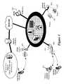
- FIG. 1illustrates a system architecture for 3 G HNB deployments in accordance with some embodiments of the invention.
- FIG. 2illustrates elements of the HNB Access Network (HNB-AN) sub-system architecture in accordance with some embodiments.
- HNB-ANHNB Access Network
- FIG. 3illustrates the Home Node-B (HNB) system architecture including the HNB-AN of some embodiments integrated with a core network of a second communication system that includes a licensed wireless radio access network.
- HNBHome Node-B
- FIG. 4illustrates some of the various devices that may be used in some embodiments in order to access services of the HNB-AN or HNB system.
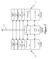
- FIG. 5illustrates the protocol architecture supporting the HNB Application Part (HNBAP) over the Iuh interface, in some embodiments.
- HNBAPHNB Application Part
- FIG. 6illustrates the protocol architecture in support of the HNB control plane (i.e., for both the CS and PS domain), in some embodiments.
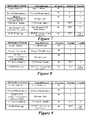
- FIG. 7illustrates INITIAL DIRECT TRANSFER message content in some embodiments.
- FIG. 8illustrates UPLINK DIRECT TRANSFER message content in some embodiments.
- FIG. 9illustrates DOWNLINK DIRECT TRANSFER message content in some embodiments.
- FIG. 10illustrates an applicable Protocol Data Unit (PDU) structure for the transport of RANAP in some embodiments.
- PDUProtocol Data Unit
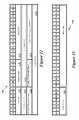
- FIG. 11illustrates an alternative PDU/RUA Adaptation Layer Structure of some embodiments.
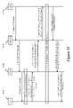
- FIG. 12illustrates the details of the RUA Header structure in some embodiments.
- FIG. 13illustrates a PDU Error Indication message in some embodiments.
- FIG. 14illustrates a RANAP message transfer using adaptation layer in some embodiments.
- FIG. 15illustrates handling of abnormal conditions over the Iuh interface in some embodiments.
- FIG. 16illustrates the CS domain transport network control signaling (using ALCAP) over the ATM-based Iu-cs interface in some embodiments.
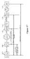
- FIG. 17illustrates the protocol architecture in support of the CS domain user plane over the Iuh interface in some embodiments.
- FIG. 18illustrates the PS Domain User Plane Protocol Architecture in some embodiments.
- FIG. 19illustrates an overview of HNB initialization, discovery and registration in some embodiments.
- FIG. 20illustrates the possible states for the HNBAP sub-layer in the HNB in some embodiments.
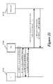
- FIG. 21illustrates the setup of UE context identifiers via UE registration in some embodiments.
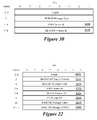
- FIG. 22illustrates the fields of an Iuh RANAP Header in some embodiments.
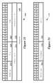
- FIG. 23illustrates a RANAP-H PDU in some embodiments.
- FIG. 24illustrates a Context Create Request (CCREQ) message in some embodiments.
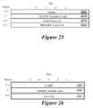
- FIG. 25illustrates an Iuh RANAP header, in some embodiments.
- FIG. 26illustrates the structure of a PDU used for transferring an HNBAP message in some embodiments.
- FIG. 27illustrates a Create UE Context Request going from the HNB to the HNB-GW in some embodiments.
- FIG. 28illustrates a Create UE Context Accept message going from the HNB-GW to the HNB in some embodiments.
- FIG. 29illustrates a Release UE Context message going from either the HNB-GW to the HNB or the HNB to the HNB-GW in some embodiments.
- FIG. 30illustrates a Release UE Context Complete message going from either the HNB-GW to the HNB or the HNB to the HNB-GW in some embodiments.
- FIG. 31illustrates the case when the HNB powers on and does not have stored information on the Serving HNB-GW, and then performs a discovery procedure with the provisioning HNB-GW and SeGW in some embodiments.
- FIG. 32illustrates the HNB Power on registration procedure in some embodiments.
- FIG. 33illustrates UE registration with the HNB in some embodiments.
- FIG. 34illustrates a procedure for the HNB-GW to allow UE registration using temporary identity in some embodiments.
- FIG. 35illustrates the UE rove out procedure, where the UE leaves the HNB coverage area while idle in some embodiments.
- FIG. 36illustrates the case when the UE powers down and performs an IMSI detach via the HNB access network in some embodiments.
- FIG. 37illustrates the loss of Iuh interface capacity for the HNB in some embodiments.
- FIG. 38illustrates an HNB-initiated register update between the HNB and HNB-GW in some embodiments.
- FIG. 39illustrates the HNB-GW-initiated registration update between the HNB and HNB-GW in some embodiments.
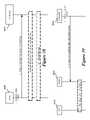
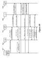
- FIG. 40illustrates the CS Handover from HNB to UTRAN in some embodiments.
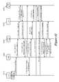
- FIG. 41illustrates the CS handover from HNB to GERAN procedure in some embodiments.
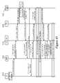
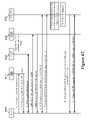
- FIG. 42illustrates the PS Handover from HNB to UTRAN in some embodiments.
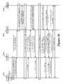
- FIG. 43illustrates the PS handover from HNB to GERAN procedure in some embodiments.
- FIG. 44illustrates CS bearer establishment (ATM transport) procedures (for MO/MT calls, using Iu-UP over AAL2) in some embodiments.
- ATM transportCS bearer establishment
- FIG. 45illustrates CS bearer establishment (IP transport) procedures (for MO/MT calls, using Iu-UP over AAL2) in some embodiments.
- FIG. 46illustrates a mobile originated call over HNB procedure in some embodiments.
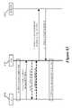
- FIG. 47illustrates a mobile terminated PSTN-to-mobile call procedure in some embodiments.
- FIG. 48illustrates a call release by an HNB subscriber procedure in some embodiments.
- FIG. 49illustrates an example relay of DTAP supplementary service messages in some embodiments.
- FIG. 50illustrates an uplink control plane data transport procedure in some embodiments.
- FIG. 51illustrates a downlink control plane data transport procedure in some embodiments.
- FIG. 52illustrates the HNB protocol architecture related to CS and PS domain SMS support builds on the circuit and packet services signaling architecture in some embodiments.
- FIG. 53illustrates a CS mode mobile-originated SMS over HNB scenario in some embodiments.
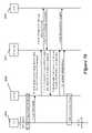
- FIG. 54illustrates an emergency call routing over HNB using service area procedure in some embodiments.
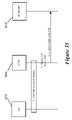
- FIG. 55illustrates an emergency call routing over HNB of an unauthorized UE using service area procedure in some embodiments.
- FIG. 56illustrates a location based emergency call routing over HNB procedure in some embodiments.
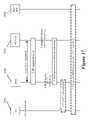
- FIG. 57illustrates HNB security mechanisms in some embodiments.
- FIG. 58illustrates message flow for security mode control over HNB in some embodiments.
- FIG. 59illustrates a CN AKA authentication over HNB procedure in some embodiments.
- FIG. 60illustrates the SAC for a new HNB connecting to the HNB network in some embodiments.
- FIG. 61illustrates the SAC for an HNB getting redirected in HNB network in some embodiments.
- FIG. 62illustrates the SAC for an HNB registering in a restricted UMTS coverage area in some embodiments.
- FIG. 63illustrates the SAC for an unauthorized UE accessing an authorized HNB in some embodiments.
- FIG. 64conceptually illustrates a computer system with which some embodiments are implemented.
- Some embodimentsprovide methods and systems for integrating a first communication system with a core network of a second communication system that has a licensed wireless radio access network.
- the first communication systemincludes one or more user hosted access points that operate using short range licensed wireless frequencies in order to establish service regions of the first communication system and a network controller for communicatively coupling the service regions associated with the access points to the core network.
- the first communication system of some embodimentsincludes a Home Node-B (HNB) Access Network (HNB-AN) where the access points are Home Node-Bs and the network controller is a HNB Gateway (HNB-GW).
- the licensed wireless radio access network of the second communication system of some embodimentsincludes a Universal Mobile Telecommunications System (UMTS) Terrestrial Radio Access Network (UTRAN) and the core network of the second communication system includes a core network of the UMTS.
- UMTSUniversal Mobile Telecommunications System
- UTRANUniversal Mobile Telecommunications System
- the network controller of some embodimentsseamlessly integrates each of the short range licensed wireless service regions with the core network.
- the network controllerseamlessly integrates with the core network by using existing Iu interfaces of the core network to communicatively couple each of the service regions to the core network.
- the network controller of some embodimentsuses standardized messaging and protocols to communicate with the core network while utilizing HNB-AN messaging and protocols to communicate with each of the service regions.
- the network controller of some embodimentsreduces deployment costs of the HNB-AN within the UMTS core network.
- deployment of the network controller of some embodimentsrequires no change to the UMTS core network while still providing HNB wireless service that combines the mobility of licensed wireless networks with the quality and speed of landline/broadband services.
- the network controllerstake on some of the functionality of a traditional Radio Network Controller (RNC).
- RNCRadio Network Controller
- the access points of some embodimentsseamlessly integrate with existing user equipment (UE) of the licensed wireless radio access networks of the second communication system.
- UEuser equipment
- the access pointsreduce deployment costs of the HNB-AN, as users are able to utilize existing UE in order to wirelessly communicate through either the first communication system or the second communication system where the first communication system combines the wireless mobility afforded by the licensed wireless radio access network of the second communication system with the speed and quality of service afforded by landline/broadband services.
- the access pointsare functionally equivalent to a Node-B of the UTRAN while having the flexibility and lower deployment costs associated with an ad-hoc and user hosted service region.
- the access pointstake on some the functionality of a traditional Radio Network Controller (RNC).
- RNCRadio Network Controller
- Some embodimentsdefine multi-layered protocol stacks for implementing management functionality within the access points and the network controller of the first communication system.
- the protocol stacksinclude a management layer that performs functionality of the HNB Application Part (HNBAP) protocol.
- HNBAPHNB Application Part
- the protocol stacks of some embodimentsimplement management functionality that includes a registration procedure for registering a particular access point with the network controller.
- the protocol stacksenable a registration procedure that allows a service region associated with a particular access point to access services of the core network through the network controller.
- Additional management functionality implemented by the protocol stacks of some embodimentsinclude discovery procedures for identifying a network controller with which the particular access point is to register.
- the protocol stacksinclude a Radio Access Network Application Part (RANAP) user adaptation (RUA) layer that enables a method for transparently passing RANAP messages between the access points and the network controller over a reliable transport connection.
- the methodreceives a RANAP message and encapsulates the message with a RUA header.
- the methodthen passes the encapsulated message to a receiving endpoint within the first communication system. In this manner, the RANAP message is passed from a first endpoint of the first communication system to a second endpoint of the first communication system.
- RANAPRadio Access Network Application Part
- RUARadio Access Network Application Part
- the network controllerdecodes and processes only the RUA header before relaying the RANAP message to the core network operating within a service region of the first communication system.
- an access pointperforms the RANAP encapsulation and the receiving endpoint is a network controller.
- the network controllerperforms the RANAP encapsulation and the receiving endpoint is an access point.
- the receiving endpointneed only decode and process the RUA header.
- RANAPis only used to communicate with core network.
- the communication with UEe.g. by the HNB uses the RRC protocol as per 3GPP 25.331 specifications.
- the HNB on the receiving endprocesses the RUA as well as the entire RANAP message.
- the content of the RANAP messagesare extracted by the HNB and converted to appropriate RRC messages.
- Some embodimentsdefine messaging formats to be used in conjunction with the various protocol stacks. Some embodiments provide a message that when sent from a particular access point to the network controller explicitly indicates the start of a communication session between the particular access point and the network controller. In some embodiments, the contents of the message are used to route the establishment of a signaling connection from the network controller to a core network node within a core network domain identified by the message.
- Some embodimentsprovide a computer readable storage medium of an access point that stores a computer program.
- the computer programincludes instructions that are executable by one or more processors.
- the computer programincludes a set of instruction for generating a message to send to the network controller to explicitly indicate start of a communication session with the network controller.
- the messageincludes a Radio Access Network Application Part (RANAP) message for establishing a signaling connection with the network controller.
- the computer programalso includes a set of instructions for passing a set of RANAP messages to the core network through the network controller after establishing the signaling connection.
- the set of RANAP messagesfacilitates communications between the particular access point and the core network.
- RANAPRadio Access Network Application Part
- Some embodimentsprovide a computer readable storage medium of a particular access point that stores a computer program.
- the computer programincludes instructions that are executable by one or more processors.
- the computer programincludes a set of instruction for receiving a message to explicitly indicate start of a communication session with a particular access point.
- the messageincludes a Radio Access Network Application Part (RANAP) message that is encapsulated with a header of the second network.
- RANAPRadio Access Network Application Part
- the messageis used for establishing a signaling connection with the particular access point.
- the computer programalso includes a set of instructions for analyzing the message header to identify a destination in the core network to receive the message.
- the computer programfurther includes a set of instructions for forwarding the message without the header to the destination in the core network to establish the signaling connection
- Some embodimentsfurther provide messages for directly transferring data downstream from the core network through the first communication system to a UE operating within a particular service region. Some embodiments provide messages for directly transferring data upstream from a UE in a particular service region through the first communication system to the core network. Directly transferring data involves routing a RANAP message through the network controller and an access point where the contents of the RANAP message are not processed by the network controller. In some embodiments, the network controller may process and modify the content of some of the RANAP message (for example, transport network switching that is converting ATM transport from/to the core network into the appropriate IP transport over the HNB-AN).
- Some embodimentsprovide a computer-readable medium that is encoded with a data storage structure.
- the data storage structurefor passing a Radio Access Network Application Part (RANAP) message within a first communication system that includes several user hosted access points for establishing service regions of the first communication system by using short range licensed wireless frequencies and a network controller that can communicatively couple user equipment operating in the service regions to a core network of a second communication system that also includes a licensed wireless radio access network.
- the data storage structurehas a header that includes a core network domain identity to identify at least one of a core network domain from which the RANAP message originated and a core network domain for which the RANAP message is to be sent.
- the headeralso includes a context identifier to uniquely identify a particular user equipment operating within a particular service region of the second communication system.
- the data storage structurealso includes payload data that include the RANAP message.
- the registration procedure of some embodimentsspecifies a method for registering UEs with the first communication system.
- the methodfrom an access point coupled to a UE sends a registration request message to the network controller on behalf of the UE.
- the methodreceives a registration accept message when the UE is authorized to access services of the first communication system through the particular access point.
- some embodimentsinclude a uniquely assigned context identifier that identifies the UE while the UE is connected for service at the particular access point. All subsequent messages will include the assigned context identifier to identify the UE.
- the registration procedure of some embodimentsalso specifies a method for registering an access point with the network controller.
- the methodincludes the access point sending its identification information and location information to the network controller.
- the network controllerdetermines whether the access point identified by the identification information at the specified location is permitted to access services of the first communication system through the network controller. When permitted, the access point receives a registration accept message from the network controller. Otherwise, the method rejects the access point or redirects the access point to another network controller.
- Some embodimentsprovide emergency responders the ability to locate a position of an emergency caller when the caller places the emergency request through a service area of the first communication system. More specifically, some embodiments provide a method whereby unauthorized UEs are still permitted limited service to the first communication system in order to establish an emergency call when in a service region of the first communication system.
- the methodincludes receiving, at a particular access point, a service request from a UE indicating that the UE is requesting emergency services.
- the particular access pointthen performs a registration procedure with the network controller that indicates that the purpose of the registration is to request emergency services for the UE.
- the methodincludes receiving a registration accept message with a context identifier to be used by the UE in order to access limited services of the first communication system, specifically, emergency services.
- Some embodimentsprovide a method that at the network controller, establishes a bearer connection between a particular access point and the core network.
- the establishing the bearer connectionincludes initiating signaling to establish an asynchronous transfer mode (ATM) based bearer connection between the network controller and the core network.
- the establishing the bearer connectionalso includes establishing an Internet Protocol (IP) based bearer connection between the network controller and the particular service region.
- IPInternet Protocol
- the methodalso includes receiving a message from the particular access point for establishing a user plane between the particular access point and the core network.
- the methodalso includes establishing the user plane by using the IP based bearer connection between the particular access point and the network controller and the ATM based bearer connection between the network controller and the core network.
- the network controllerroutes user plane data received from the particular access point over the IP based bearer connection to the core network through the ATM based bearer connection by the network controller.
- Some embodimentsprovide a method for user equipment (UE) registration with a closed subscriber group (CSG) system.
- the methodreceives a UE registration request at the network controller from an access point.
- the requestincludes an initial NAS message from the UE and a CSG identification associated with the access point.
- the methodrelays the registration request that includes the initial NAS message and the CSG identification to the core network.
- the methodreceives a permanent identity of the UE from the core network based on the registration request.
- the methoduses the permanent identity of the UE to complete the UE registration.
- Section Idiscusses the HNB system architecture.
- Section IIdescribes various protocol architectures of the HNB system, including protocol architectures for the Home Node-B Application Part (HNBAP) and the Radio Access Network Application Part (RANAP) User Adaption (RUA) layer.
- Section IIIdiscusses mobility management within the HNB system, including mobility management scenarios and relocation.
- Section IVdescribes call management and some call management scenarios.
- Section Vdiscusses packet services.
- Section VIdiscusses short message services and scenarios.
- Section VIIdescribes emergency services, including service area based routing and location based routing.
- Section VIIIdiscusses Lawfully Authorized Electronic Surveillance (LAES) Service.
- LAESLawfully Authorized Electronic Surveillance
- Section IXdiscusses HNB security, including authentication, encryption, a profile of IKEv2, a profile of IPSec ESP, security mode control, and core network authentication.
- Section Xdescribes HNB service access control (HNB SAC), including HNB-GW and service area selection, and service access control use case examples.
- Section XIanalyzes the impacts of various access control policies.
- Section XIIprovides a description of a computer system with which some embodiments of the invention are implemented.
- Section XIIIlists the abbreviations and provides definitions for terms found herein.
- FIG. 1illustrates a system architecture for 3 G HNB deployments in accordance with some embodiments of the invention.
- the systemincludes a HNB access network (or HNB system) 110 .
- the key features of the 3 G HNB system architectureinclude (a) support for a standard User Equipment (UE) 105 as defined in the 3GPP technical specification TS 23.101 entitled “General UMTS architecture” which is incorporated herein by reference and (b) co-existence with the UMTS Terrestrial Radio Access Network (UTRAN) and interconnection with the existing Core Network (CN) 115 via the standardized interfaces defined for UTRAN.
- UEUser Equipment
- CNCore Network
- the standardized interfacesinclude (a) the Iu-cs interface for circuit switched services as overviewed in the 3GPP technical specification (TS) 25.410 entitled “UTRAN Iu Interface: general aspects and principles” which is incorporated herein by reference, (b) the Iu-ps interface for packet switched services as overviewed in the 3GPP TS 25.410, (c) the Iu-pc interface for supporting location services as described in the 3GPP TS 25.450 entitled “UTRAN Iupc interface general aspects and principles” which is incorporated herein by reference, and (d) the Iu-bc interface for supporting cell broadcast services as described in the 3GPP TS 25.419 entitled “UTRAN Iu-BC interface: Service Area Broadcast Protocol (SABP)” which is incorporated herein by reference.
- SABPService Area Broadcast Protocol
- some embodimentsutilize existing Iu and Uu interfaces within the HNB-AN 110 .
- the HNB-AN 110addresses some of the key issues in the deployment of 3 G HNB applications, such as the ad-hoc and large scale deployment of 3 G HNBs using public infrastructure such as the Internet.
- FIG. 2illustrates elements of the HNB Access Network (HNB-AN) 200 architecture in accordance with some embodiments.
- This figureincludes (3 G) HNB 205 , Generic IP Access Network 210 , HNB-GW 215 , HNB Management System 220 , Iuh interface 225 that is established between the Generic IP Access Network 210 and the HNB-GW 215 , and an interface 230 between the HNB-GW 215 and the HNB Management System 220 .
- the interface 230is based on the 3GPP TR-069 family of standards.
- the interface 230is the Iuhm interface.
- FIG. 2 and other figures belowillustrate a single access point (e.g., HNB 205 ) communicatively coupled to a network controller (e.g., HNB-GW 215 ).
- a network controllere.g., HNB-GW 215
- the network controllere.g., HNB-GW 215
- the network controllercommunicatively coupled to several HNBs and the network controller communicatively couples all such HNBs to the core network.
- the HNB of some embodimentsis communicatively coupled to several UEs.
- the figuresmerely illustrate a single HNB communicatively coupled to the HNB-GW for purposes of simplifying the discussion to interactions between a single access point and a single network controller. However, the same network controller may have several of the same interactions with several different access points.
- FIG. 3illustrates the HNB-AN system architecture of some embodiments integrated with a core network of a second communication system that includes a licensed wireless radio access network.
- the HNB systemincludes (1) Home Node-B (HNB) 305 , (2) Home Node-B Gateway (HNB-GW) 315 , (3) Broadband IP Network 320 , (4) Security Gateway (SeGW) 325 , and (6) HNB Management System 330 .
- the licensed wireless radio access network of the second communication systemincludes UTRAN 385 which is comprised of a Node-B 380 and a Radio Network Controller 375 of a UMTS.
- the core network of the second communication systemincludes Mobile Switching Center (MSC) 365 , Serving GPRS Support Node (SGSN) 370 , Authorization, Authentication, and Accounting server 355 , and Home Location Register 360 . Additionally, Service Mobile Location Center (SMLC) 340 and Cell Broadcast Center (CBC) 345 may be components of the core network.
- MSCMobile Switching Center
- SGSNServing GPRS Support Node
- CBCCell Broadcast Center
- UEUser Equipment
- UE 310is used to access services of the HNB-AN and also access services of the licensed wireless radio access network 385 of a cellular provider. In some such embodiments, the UE seamlessly transitions from the HNB-AN to the cellular provider and vice versa without loss of connectivity. In some embodiments, the UE 310 is thus a standard device operating over licensed spectrum of a licensed wireless system provider. Accordingly, the UE 310 wirelessly connects to the HNB 305 using the same signaling and messaging interfaces as it would when connecting to a base station, such as a base transceiver station (BTS) in GSM, or the Node-B 380 of a Universal Mobile Telecommunications System (UMTS).
- BTSbase transceiver station
- UMTSUniversal Mobile Telecommunications System
- FIG. 4illustrates some of the various devices that may be used in some embodiments in order to access services of the HNB-AN or HNB system.
- the devicesinclude (1) standard licensed wireless handsets 405 and wireless enabled computers 410 that connect through an HNB 415 , (2) dual mode handsets with WiMAX capabilities 420 that connect through WiMAX access points 425 , (3) devices such as wired telephones 430 and faxes 435 that connect through terminal adapters 440 , and (4) softmobile enabled devices 445 .
- the UE 310includes cellular telephones 405 , smartphones, PDAs, and modem like devices some of which are shown in FIG. 4 .
- These devicesinclude any device that wirelessly communicates with a licensed wireless service provider using existing licensed wireless technologies, such as Global System for Mobile (GSM) communications, UMTS, etc.
- GSMGlobal System for Mobile
- the UE 310includes a terminal adaptor device (such as 440 of FIG. 4 ) that allows incorporating fixed-terminal devices such as telephones, faxes, and other equipments that are not wirelessly enabled within the HNB-AN.
- a terminal adaptor devicesuch as 440 of FIG. 4
- fixed-terminal devicessuch as telephones, faxes, and other equipments that are not wirelessly enabled within the HNB-AN.
- the servicebehaves as a standard analog fixed telephone line.
- the serviceis delivered in a manner similar to other fixed line VoIP services, where a UE is connected to the subscriber's existing broadband (e.g., Internet) service.
- broadbande.g., Internet
- the UE 310includes a dual mode cellular/WiMAX UE (such as 420 of FIG. 4 ) that enables a subscriber to seamlessly transition between a cellular network and a WiMAX network through a WiMAX access point (such as 425 of FIG. 4 ).
- a dual mode cellular/WiMAX UEsuch as 420 of FIG. 4
- a WiMAX access pointsuch as 425 of FIG. 4
- the UE 310 of some embodimentsincludes SoftMobile like devices.
- a subscriberwould place a USB memory stick with an embedded SIM into a USB port of their laptop.
- a SoftMobile clientwould automatically launch and connect over IP to the mobile service provider. From that point on, the subscriber would be able to make and receive mobile calls as if she was in her home calling area.
- the Home Node-B (HNB) 305is an access point that offers a standard radio interface (Uu) for user equipment (UE) connectivity using short range licensed wireless frequencies.
- the HNB 305provides the radio access network connectivity to the UE using the Iuh interface towards the HNB-GW 315 .
- the HNB 305differs from the UMTS Node-B in that the range of wireless connectivity supported by the HNB 305 (e.g., tens of meters) is much less than the range supported by the UMTS Node-B (e.g., hundreds or thousands of meters). This is because the HNB 305 is a low power and a short range device similar to wireless access points found within a user's home. The low power and short range requirement ensures that the HNB 305 does not interfere with the service regions of the licensed wireless system providers (e.g., cellular networks) that are established using the wireless frequencies that the licensed wireless system providers licensed from the government at great expense. Moreover, the low power requirement enables the HNB 305 to operate using standard electrical outlets of a user's home or office.
- the licensed wireless system providerse.g., cellular networks
- the low power and short range requirementfurther facilitates the small scale of the HNB device relative to the radio access network Node-B devices.
- the HNBis a much smaller device often the size of 802.11 wireless routers commonly found within a user's home.
- the Node-Bis network equipment of a UMTS Terrestrial Radio Access Network (UTRAN).
- the Node-Bis managed and operated by a licensed wireless system provider.
- the Node-B of the licensed wireless systemhas to provide service to many more users than the HNB 305 and must do so without loss of connectivity over vast regions (e.g., states and countries).
- the licensed wireless service providerdeploys several Node-Bs that are adjacent to one another in order to create an uninterrupted region of coverage.
- an HNB service region established by a first HNBdoes not need to be adjacent to any other HNB service region and need not offer uninterrupted service between HNB service regions.
- the HNB 305is user hosted as opposed to the Node-B that is hosted by the licensed wireless system.
- a user hosted HNBallows a user to specify the location of the HNB, provide the connectivity between HNB and the HNB network or HNB-GW (e.g., the broadband connection), control operation of the HNB, for example, by providing power to the HNB, or manage the HNB by modifying configuration parameters of the HNB. All such control over the Node-B is tightly managed by the licensed wireless system provider.
- the HNBis customer premise equipment (CPE) that a user is able to purchase from an electronics store or from the HNB-AN provider, whereas the Node-B is network equipment that is impractical for a single user to purchase, operate, and maintain.
- CPEcustomer premise equipment
- HNB architecturea key characteristic of the HNB architecture of some embodiments is that there are no permanent pre-configured peer adjacencies between HNB and HNB-GW. Instead, there are ad-hoc adjacencies that are initiated from the HNB (as it is usually behind a NAT/firewall, and does not have a permanent IP address in the carrier network).
- the HNB systemtherefore offers flexibility in deploying service.
- the HNBs of an HNB systemmay be deployed on an ad hoc basis as opposed to the regimented deployment structure of the licensed wireless system.
- the HNB 305supports enhancements for operating in an ad-hoc environment and the Node-B does not.
- the ad hoc systemallows for individual users to establish HNB service regions based on each user's needs.
- each userpurchases an HNB and each of the HNBs may be purchased from different vendors with different HNB implementations.
- the ad hoc HNB systemcreates several individual local coverage areas based on user deployment of each HNB whereas the licensed wireless system deploys its Node-Bs in an effort to provide regional coverage area that is uninterrupted across large areas (e.g., hundreds of miles).
- the HNB system providerdeploys the HNBs rather than the users.
- the systemremains ad hoc by virtue of the discontinuous nature of the separate and local HNB service regions.
- the HNBsremain user hosted since power and broadband connectivity is provided by the user even though the system provider more closely regulates the HNB equipment that is deployed.
- the ad hoc nature of the HNB systemalso allows the system to grow and shrink as its user base grows and shrinks. For example, whenever a new user desires to utilize the HNB service, the user purchases and hosts a HNB at a home or office location. The user hosted HNB provides the user with a HNB-AN service region from which the user access HNB system services. Conversely, the licensed wireless system provider must first deploy several Node-Bs in order to provide extensive large scale regional coverage. Once the service regions are established at great expense to the licensed wireless system provider, users then activate service with the licensed wireless system provider. Accordingly, the HNB system is an unplanned system whereas the licensed wireless system is a planned system. In other words, the HNB system does not need an existing access point infrastructure in order to operate.
- the licensed wireless systemrequires that there be an existing infrastructure before new users can be added.
- the infrastructure of the licensed wireless systemis planned in the sense that the infrastructure is built first in a particular region and then the service is marketed to that region after the infrastructure is built.
- the HNB 305also differs from generic access points used in UMA systems. Specifically, in a UMA system the access points act as transparent base stations. In other words, the user equipment and the network controller directly communicate. In the HNB system, however, the HNB 305 includes various Radio Network Controller (RNC) functionality. In some such embodiments, the HNB 305 initiates various messaging procedures and maintains state information regarding user equipment operating within the service region associated with the HNB 305 .
- the HNB 305is equipped with either a standard 3 G Universal Subscriber Identity Module (USIM) or a 2 G SIM.
- USIMUniversal Subscriber Identity Module
- SIM2 G SIM
- the HNB identity of some embodimentsis based on Media Access Control (MAC) address of the HNB or any other globally unique identifier such as the combination of vendor identity and serial number from that vendor.
- MACMedia Access Control
- the access points of some embodimentsinclude circuits for receiving, transmitting, generating, and processing the various messages that cause various physical transformations within the HNB-AN, core network, and licensed wireless radio access network.
- the circuits of the access pointsinclude a processor, memory, receiver, and transceiver.
- the receiver and/or the transceiverare wireless interfaces that operate using short range licensed wireless frequencies.
- the receiver and/or the transceiverare wired interfaces (e.g., DSL, cable, etc.). These circuits perform various physical transformations on the access point as well as other elements within the HNB-AN, licensed wireless radio access network, and core network.
- the processor in conjunction with the memorygenerate a paging message that when sent to a UE using the transceiver causes the UE to prompt the user of an incoming call.
- the access pointregisters a UE by generating a registration message that is sent to the network controller using the transceiver when the access point detects that the UE has camped on the service region of the access point based on a location update message received by the access point on its receiver.
- the HNBis one implementation of an access point that operates using short range licensed wireless frequencies. Some embodiments allow for any access point that operates using short range licensed wireless frequencies to be used in place of or in conjunction with the HNBs.
- a Femtocell access pointis a different implementation of an access point that provides short range licensed wireless frequencies in order to establish a service region of a Femtocell system that is similar to the HNB system described in relation to some embodiments of the invention.
- the HNB 305provides radio access network connectivity for the UE 310 .
- the HNB 305then communicatively couples the UE to the HNB-GW 315 using the Iuh interface that exists between the HNB 305 and the HNB-GW 315 .
- the Iuh interfaceis established over a broadband Internet Protocol (IP) network 320 where, in some embodiments, a customer's broadband connection is utilized.
- IPInternet Protocol
- the broadband IP Network 320represents all the elements that collectively, support IP connectivity between the HNB-GW 315 and the HNB 305 .
- the IP network 320is assumed to be an untrusted public IP network without any Asynchronous Transfer Mode (ATM) or Signaling System 7 (SS7) infrastructure.
- ATMAsynchronous Transfer Mode
- SS7Signaling System 7
- the broadband IP network 320includes (1) other Customer premise equipment (e.g., Digital Subscriber Line (DSL)/cable modem, Wireless Local Area Network (WLAN) switch, residential gateways/routers, switches, hubs, WLAN access points), (2) network systems specific to the broadband access technology (e.g., DSL Access Multiplexer (DSLAM) or Cable Modem Termination System (CMTS)), (3) Internet Service Provider (ISP) IP network systems (edge routers, core routers, firewalls), (4) wireless service provider (WSP) IP network systems (edge routers, core routers, firewalls) and Network address translation (NAT) functions, either standalone or integrated into one or more of the above systems.
- DSL Access MultiplexerDSL Access Multiplexer
- CMTSCable Modem Termination System
- ISPInternet Service Provider
- WSPwireless service provider IP network systems
- NATNetwork address translation
- the HNB-GW 315is a network controller that provides network connectivity of the HNB 305 to the existing core network (CN) 335 .
- the HNB-GW 315 entityappears as a legacy RNC to the existing CN 335 .
- the HNB-GW 315uses existing Iu interfaces (e.g., Iu-cs and Iu-ps) for CN connectivity.
- Iu-cs and Iu-psexisting Iu interfaces
- the HNB systemmay be integrated into the existing CN 335 with no change to the CN 335 . This allows licensed wireless system providers the ability to provide HNB system functionality to their users with no change to their existing network.
- the HNB-GW 315connects to the HNB 305 using the Iuh interface. Additional interfaces of the HNB-GW 315 include the Iu-pc interface to the Service Mobile Location Center (SMLC) 340 , the Iu-bc interface to the Cell Broadcast Center (CBC) 345 , the Wm interface to the Authorization, Authentication, and Accounting (AAA) server 355 , and an interface that is based on the 3GPP TR-069 family of standards, as specified by the DSL Forum technical specifications, to the HNB management system 330 . In some embodiments, the interface to the HNB management system 330 is the Iuhm interface.
- SMLCService Mobile Location Center
- CBCCell Broadcast Center
- AAAAuthorization, Authentication, and Accounting
- the interface to the HNB management system 330is the Iuhm interface.
- the Iuhm interfacecarries information related to customer premise equipment (CPE) device management functionality between the HNB and HNB Mgmt System. It should be apparent to one of ordinary skill in the art that other interfaces may be used instead of or in addition to the above enumerated interfaces.
- CPEcustomer premise equipment
- the HNB-GW 315connects to several different HNBs and services each of the corresponding service regions of each of the several HNBs.
- a single HNB-GWsuch as the HNB-GW 315 , communicatively couples multiple HNB service regions to the CN 335 .
- the HNB-GW 315provides call management functionality, mobility management functionality, security functionality, etc. as will be described in greater detail below.
- the HNB-GW 315also performs key functionalities, such as the management of the legacy UTRAN identifiers (Location Area Identifiers (LAI), Service Area Identifiers (SAI), RND-Id, etc.) towards the CN 335 , and Iuh interface management.
- LAILocal Area Identifiers
- SAIService Area Identifiers
- RND-IdRadio Network-Id
- the HNB-GW 315includes various software module sub-components and/or various hardware module sub-components that perform some of the above mentioned functionality.
- the Security Gateway (SeGW) 325is a logical entity within the HNB-GW 315 .
- the SeGW 325provides the security functions including termination of secure access tunnels from the HNB 305 , mutual authentication, encryption and data integrity for signaling, voice and data traffic.
- the HNB Management System 330provides centralized Customer Premise Equipment (CPE) device management for the HNB 305 and communicates with the HNB 305 via the security gateway logical entity. This system is used to manage a large number of HNBs including configuration, failure management, diagnostics, monitoring and software upgrades. In some embodiments, the HNB Management System 330 utilizes existing CPE device management techniques such as those described in the DSL Forum technical specifications TR-069.
- CPECustomer Premise Equipment
- the network controller of some embodimentsincludes circuits for receiving, transmitting, generating, and processing the various messages that cause various physical transformations within the HNB-AN, core network, and licensed wireless radio access network.
- the circuits of the network controllerinclude a processor, memory, receiver, and transceiver. These circuits perform various physical transformations on the network controller as well as other elements within the HNB-AN, licensed wireless radio access network, and core network.
- the processorin conjunction with the memory generates context identifiers that when sent to a UE using the transceiver provide the UE with a unique identifier when operating within the HNB-AN.
- the HNB-GW 315provides network connectivity of the HNB 305 to the existing CN 335 .
- the CN 335includes one or more HLRs 360 and AAA servers 355 for subscriber authentication and authorization. Once authorized, the UE may access the voice and data services of the CN 335 through the HNB system.
- the CN 335includes a Mobile Switching Center (MSC) 365 to provide circuit switched services (i.e., voice).
- the CNalso includes a Serving GPRS Support Node (SGSN) 370 to provide packet switched services. Though not shown in FIG. 3 , the SGSN operates in a conjunction with a Gateway GPRS Support Node (GGSN) in order to provide the packet switched services.
- MSCMobile Switching Center
- SGSNServing GPRS Support Node
- GGSNGateway GPRS Support Node
- the SGSN 370is typically responsible for delivering data packets from and to the GGSN and the UE within the geographical service area of the SGSN 370 . Additionally, the SGSN 370 may perform functionality such as mobility management, storing user profiles, and storing location information. However, the actual interface from the CN 335 to various external data packet services networks (e.g., public Internet) is facilitated by the GGSN. As the data packets originating from the UE typically are not structured in the format with which to access the external data networks, it is the role of the GGSN to act as the gateway into such packet services networks. In this manner, the GGSN provides addressing for data packets passing to and from the UE and the external packet services networks (not shown). Moreover, as the user equipment of a licensed wireless network traverses multiple service regions and thus multiple SGSNs, it is the role of the GGSN to provide a static gateway into the external data networks.
- the GGSNprovides addressing for data packets passing to and from the UE and the external packet
- the CBC 345provides support for cell broadcast services.
- the licensed wireless systemwill be described with reference to the UTRAN of a UMTS. However, it should be apparent to one of ordinary skill in the art that any licensed wireless system, such as a GSM/EDGE Radio Access Network (GERAN) may be used to reference the licensed wireless system.
- GERANGSM/EDGE Radio Access Network
- Elements common to a UTRAN based cellular networkinclude multiple base stations referred to as Node-Bs that facilitate wireless communication services for various UE via respective licensed radio links (e.g., radio links employing radio frequencies within a licensed bandwidth).
- the licensed wireless channelmay comprise any licensed wireless service having a defined UTRAN or GERAN interface protocol (e.g., Iu-cs and Iu-ps interfaces for UTRAN or A and Gb interfaces for GERAN) for a voice/data network.
- the UTRAN 385typically includes at least one Node-B 380 and a Radio Network Controller (RNC) 375 for managing the set of Node-Bs.
- RNCRadio Network Controller
- the multiple Node-Bsare configured in a cellular configuration (one per each cell) that covers a wide service area.
- a licensed wireless cellis sometimes referred to as a macro cell which is a logical term used to reference, e.g., the UMTS radio cell (i.e., 3 G cell) under Node-B/RNC which is used to provide coverage typically in the range of tens of kilometers.
- the UTRAN or GERANis sometimes referred to as a macro network.
- Each RNCcommunicates with components of the core network through the above described standard radio network controller interface such as the Iu-cs and Iu-ps interfaces.
- a RNCcommunicates with MSC via the UTRAN Iu-cs interface for circuit switched services.
- the RNCcommunicates with SGSN via the UTRAN Iu-ps interface for packet switched services through GGSN. It is through the use of these standardized network interfaces that the HNB system, more particularly the HNB-GW, may be seamlessly integrated to leverage services of the CN and emulate functionality of a legacy RNC of the licensed wireless system.
- the protocol stacksinclude software layers that are stored to the memory of the HNB and HNB-GW and that are executed by a processing unit of the HNB and HNB-GW.
- the protocol stacksare implemented as hardware modules within the HNB and HNB-GW. Additional hardware components of the HNB and HNB-GW are described below in Section XII, “Computer System”.
- the HNB systemseparates management functions from control plane functions into two separate protocol stacks.
- the HNB Application Part (HNBAP) protocol architectureimplements the management functions for the HNB system and the RANAP User Adaptation (RUA) protocol architecture implements the control functions for the HNB system.
- HNBAPHNB Application Part
- ROAUser Adaptation
- additional protocol architecturesare specified for providing other functionality such as user plane functionality.
- other protocol architecturesmay be integrated into the components of the HNB system and that the functionality of each of the protocol architectures is scalable to provide more or less functionality than described below.
- HNBAPHNB Application Part
- the HNBAP protocol architecturesupports management functions between the HNB and HNB-GW including, but not limited to, the management of the underlying transport (i.e., the SCTP connection), HNB-GW discovery, and HNB and UE registration procedures.
- FIG. 5illustrates the HNBAP protocol architecture in accordance with some embodiments. This figure illustrates (1) HNB 505 , (2) HNB-GW 515 , and (3) HNBAP protocol stacks of each of the HNB 505 and the HNB-GW 515 .
- the HNBAP protocol stacksinclude (1) access layers 510 , (2) transport IP layer 520 , (3) IP Security (IPSec) ESP layer 525 , (4) remote IP layer 540 , (5) Stream Control Transmission Protocol layer (SCTP) 530 , and (6) a HNBAP protocol layer 545 .
- IPSecIP Security
- SCTPStream Control Transmission Protocol layer
- the underlying Access Layers 510 and “Transport IP” layer 520(i.e., the “outer” IP layer associated with IPSec tunnel mode) provide the generic connectivity between the HNB 505 and the HNB-GW 515 .
- the IPSec layer 525operates in tunnel mode and provides encryption and data integrity for communications and data that are passed using the upper layers ( 530 , 540 , and 545 ).
- SCTP 530provides reliable transport between the HNB 505 and the HNB-GW 515 .
- SCTP 530is transported using the “Remote IP” layer 540 (i.e., the “inner” IP layer associated with IPSec tunnel mode).
- the SCTP 530establishes a single SCTP association between the HNB 505 and HNB-GW 515 .
- the same SCTP associationis used for the transport of both the HNBAP messages as well as the RANAP messages (using RUA protocol), described in further detail below, over the Iuh interface 535 .
- the SCTP Payload Protocol Identifier (PPI) valueis used to identify the protocol being transported in the SCTP data chunk (e.g., HNBAP or RUA).
- the PPI value used for HNBAP transportis coordinated between the HNB 505 and the HNB-GW 515 (e.g., the HNBAP PPI value should be registered with the Internet Assigned Numbers Authority (IANA)).
- Each SCTP associationcontains a number of “streams” which are used to support multiple flows across the Iuh interface.
- a dedicated SCTP streami.e., stream id 0 of the underlying SCTP transport association
- TCPTransmission Control Protocol
- the HNBAP protocol 545provides a resource management layer or equivalent functional layer capable of discovery of the serving HNB-GW, registration of the HNB and UE with the HNB-GW, registration updates with the HNB-GW, and support for the identification of the HNB being used for HNB access. It should be apparent to one of ordinary skill in the art that the HNBAP protocol layer of some embodiments implements additional resource management functionality and that the above enumerated list is an exemplary set of such functionality. In some embodiments, the HNBAP protocol 545 utilizes different message formats and utilizes a different set of procedures than the resource management layers of the 3GPP and UMA systems in order to implement the resource management layer of the HNB system.
- the HNB and HNB-GWAfter performing the management functions defined by the HNBAP protocol, the HNB and HNB-GW utilize a different protocol architecture that specifies the control plane in the HNB system.
- FIG. 6illustrates the protocol architecture in support of the HNB control plane (i.e., for both the CS and PS domain) in accordance with some embodiments.
- FIG. 6includes (1) HNB 605 , (2) HNB-GW 615 , (3) CN 640 , (4) UE 650 , and (5) control plane protocol stacks of each of the HNB 605 , the HNB-GW 615 , the CN 640 , and the UE 650 .
- the control plane protocol stacks of the HNB 605 and the HNB-GW 615include (1) access layers 610 , (2) transport IP layer 620 , (3) IPSec layer 625 , (4) remote IP layer 640 , (5) SCTP 630 , (6) RANAP user adaptation (RUA) layer 635 , and (7) interworking functionality (IWF) 645 .
- IWFinterworking functionality
- the control plane protocol stack of the CN 640includes signaling transport layers defined according to the 3GPP technical specification TS 25.412, “UTRAN Iu Interface Signaling Transport”, herein incorporated by reference, a RANAP layer, and a Non Access Stratum (NAS) layer 665 that performs various call management, mobility management, General Packet Radio Service (GPRS) mobility management and session management, and short message services (SMS).
- the control plane protocol stack of the UE 650includes a layer 1 signaling transport layer, a Media Access Control (MAC) layer, a Radio Link Control (RLC) layer, a Radio Resource Control (RRC) layer, and the NAS layer 665 .
- MACMedia Access Control
- RLCRadio Link Control
- RRCRadio Resource Control
- the underlying Access Layers 610 and “Transport IP” layer 620provide the generic connectivity between the HNB 605 and the HNB-GW 615 .
- the IPSec layer 625provides encryption and data integrity for communications and data that are passed using the upper layers.
- SCTP 630provides reliable transport for the RANAP User Adaptation (RUA) layer 635 between the HNB 605 and the HNB-GW 615 .
- RUAUser Adaptation
- the RANAP protocolis used for CS/PS signaling between the HNB 605 and the CN 640 .
- RANAPas is well known in the art, is an established protocol used for UMTS signaling between the CN and the UTRAN of a licensed wireless radio access network. Accordingly, the use of RANAP messages within the control plane of the HNB system, allows for the HNB system to support many of the UTRAN functions in the HNB system. These functions include: Radio Access Bearer (RAB) management, Radio Resource Management (RRM), Iu link management, Iu U-plane (RNL) management, mobility management, security, service and network access, and Iu coordination.
- RABRadio Access Bearer
- RRMRadio Resource Management
- Iu link managementIu U-plane
- RNLIu U-plane
- the HNB-GW 615relays the RANAP messages between the HNB 605 and the CN 640 .
- the HNB-GW 615terminates and re-originates some RANAP messages.
- the HNB-GW 615terminates and re-originates connection-less RANAP messages.
- the HNB control plane protocol stacks of the HNB 605 and the HNB-GW 615include the RUA layer 635 .
- the RUA layer 635provides a lightweight mechanism to transport RANAP messages 660 and control functions between the HNB 605 and the HNB-GW 615 .
- the RUA layer 635encapsulates the RANAP messages 660 in an RUA layer header for transport between the HNB 605 and the HNB-GW 615 . Therefore, through the use of the RUA 635 layer, no changes are made to the RANAP message definitions. Rather, all necessary changes are contained in the RUA header.
- the RUA adaptation layer of some embodimentsenables: (1) transport of RANAP messages using SCTP over the Iuh interface between the HNB and HNB-GW, (2) support for associating and identifying UE specific logical connections (i.e., identifying the RANAP messages belonging to a specific UE via the concept of UE context identifiers), (3) support for routing the establishment of a signaling connection to a CN node within a CN domain (i.e., support for Iu-flex at the HNB-GW), (4) support for indicating the cause for establishing the UE specific logical connection (e.g., for emergency session establishment, etc.), (5) providing a mechanism to transparently relay the RANAP messages from the HNB to CN without the need to decode the encapsulated RANAP message, and (6) support for the indication of service domain (CS or PS) for the RANAP messaging.
- CS or PSservice domain
- the RUA layer 635minimizes the decoding and processing of RANAP messages 660 at the HNB-GW 615 . Specifically, the HNB-GW 615 , in many instances, no longer must decode and process the RANAP message 660 . Instead, the HNB-GW 615 processes information within the RUA header information in order to determine a destination within the core network to receive a RANAP message 660 sent from a UE operating from a HNB service region communicatively coupled by the HNB-GW 615 . The RUA layer 635 also eliminates the need for the HNB-GW 615 to process and decode the NAS layer 665 .
- the RUA layer 635does not duplicate existing RANAP procedures. Accordingly, RUA procedures are minimized.
- the HNB control plane protocol architecture of some embodimentssimplifies context-ID allocation and associated functional overhead.
- the RUA 635utilizes the same underlying transport (i.e., SCTP connection) as HNBAP. It should be apparent to one of ordinary skill in the art that it is also possible to use TCP as a reliable transport layer instead of SCTP.
- SCTP PPI value used for RUA transportis coordinated between the HNB 605 and the HNB-GW 615 (e.g., the RUA PPI value should be registered with IANA).
- a dedicated SCTP stream(e.g., stream id 0 of the underlying SCTP transport association) is used for the transport of connectionless RANAP messages 660 between the HNB 605 and the HNB-GW 615 .
- the number of SCTP streams to be established at SCTP connection setup and the mapping of UE transactions to the specific SCTP streamsis an implementation choice.
- the use of UE Context-Idallows multiple UE transactions to be multiplexed over the same SCTP stream.
- the Inter-working Functionality (IWF) 645 in the HNB-GW 615switches the RANAP messages 660 between the Iuh interface and the corresponding domain specific (CS/PS) Iu interface. It should be noted that the IWF 645 is a logical entity in the RUA protocol stack. As mentioned above, some RANAP messages 660 are terminated and re-originated in the HNB-GW 615 (e.g., connection-less RANAP messages) and some are modified in the HNB-GW 615 to adapt to the underlying transport towards the CN 640 (e.g., when using ATM interfaces towards the CN 640 ). Additionally, NAS protocol messages 655 (e.g., CC/MM/SMS, etc) are carried transparently between the UE 650 and the CN 640 .
- NAS protocol messages 655e.g., CC/MM/SMS, etc
- the relay of RANAP messages 660 between the HNB 605 and the CN by the HNB-GW 615is achieved using a direct transfer mechanism over the Iuh interface.
- This direct transfer mechanisminvolves encapsulation of the RANAP messages 660 in a DIRECT TRANSFER message exchanged between the HNB 605 and HNB-GW 615 over the Iuh interface.
- this messageis referred to as a RUA DIRECT TRANSFER message.
- this messageis referred to as a HNBAP DIRECT TRANSFER message.
- the direct transfer mechanismis used to relay messages from CBC (Iu-bc) (not shown) and SMLC (Iu-pc) (not shown) to HNB 605 and vice-versa via the HNB-GW 615 .
- the architecture of FIG. 6also supports transfer of the RANAP “Initial UE Message” and support for Iu-flex.
- Iu-flex functionalityis defined in 3GPP TS 23.236, “Intra-Domain Connection of Radio Access Network (RAN) nodes to multiple Core Network (CN) nodes”, hereinafter, TS 23.236, with additional functionality such as messaging, etc., described in TS 25.331.
- Iu-flexcovers details for the Intra Domain Connection of RAN Nodes to Multiple CN Nodes for GSM and UMTS systems.
- the first RANAP message(i.e., the RANAP “Initial UE Message”) is carried from the HNB 605 in the INITIAL DIRECT TRANSFER message over the Iuh interface as is described below with reference to FIG. 7 .
- the INITIAL DIRECT TRANSFER messagealso carries information used to route the establishment of a signaling connection from HNB-GW 615 to a CN node within a CN domain (i.e. support for Iu-flex).
- connection-less RANAP messagesare terminated and processed in the HNB-GW 615 .
- specific connectionless messagee.g. Paging
- the DIRECT TRANSFER messageis used to relay the specific connection-less message.
- the direct transfer mechanism for relaying RANAP messagesprovides a single protocol over the Iuh interface (i.e., clean architecture) whereby a single interface between HNB and HNB-GW functional entity is used.
- the direct transfer mechanism of some embodimentseliminates changes to the RANAP specifications for use over the Iuh interface. If RANAP were to be used directly over the Iuh interface, then all the specifications which reference RANAP would need to be updated to describe the applicability of existing RANAP messages between the two new nodes (e.g., HNB and the HNB-GW).
- the direct transfer mechanismeliminates the need for “RNC-ID” and “Iu signaling connection identifier” attributes on a per HNB basis, carried in the RANAP messages.
- the “RNC-ID” and “Iu-signaling connection identifier” carried in the downlink RANAP messagesare processed by the HNB-GW and can be ignored by the HNB.
- the usage of the RNC-ID and Iu signaling connection identifier attributescan be implementation specific with no impact on the Iuh interface.
- the overhead (management and runtime) of the underlying transport layers of RANAPsuch as SCCP/M3UA are eliminated as well.
- the HNBsends a message to the HNB-GW to transfer the RANAP “Initial UE Message” from the HNB to the indicated core network domain.
- the messageexplicitly indicates the start of a communication session and the message contains parameters used to route the establishment of a signaling connection from the HNB-GW to a CN node within a CN domain when no signaling connection exists
- this messageis an INITIAL DIRECT TRANSFER message.
- FIG. 7illustrates INITIAL DIRECT TRANSFER message content, in some embodiments.
- the INITIAL DIRECT TRANSFER messageincludes the following information elements (IEs): length indicator, protocol discriminator, message identity, CN Domain Identity, Intra Domain Non Access Stratum (NAS) Node Selector (IDNNS), and an encapsulated RANAP message.
- the CN Domain Identity information elementindicates the CN domain with which to establish the signaling connection.
- the IDNNS information elementis used by the HNB-GW to route the establishment of a signaling connection to a core network node within the indicated core network domain. By using this explicit message, the HNB-GW is explicitly notified of impending signaling connection without having to process the contents of the message.
- the presence fieldindicates whether the information element is (1) mandatory (M) where the message is erroneous if the mandatory information element is missing, (2) conditional (C) where the presence of the information element depends on a value of a different information element, or (3) optional (O) where the presence of the information element is the choice of the sender.
- the format fieldindicates how the message is formatted.
- Type only (T) or Type and value (TV)indicates that the information element is of fixed length and an information element identifier is included.
- Value only (V)indicates that the information element is of fixed length but no information element identifier is included.
- Length and value (LV)indicates that the information element is of variable length, an information element identifier is not included, and a length indicator is included.
- Type, length, and value (TLV)indicates that the information element is of variable length and that an information element identifier and a length indicator are included.
- the HNBsends a message to the HNB-GW to transfer a subsequent (i.e., other than the initial RANAP message) RANAP message from the HNB to the indicated core network domain.
- this messageis an UPLINK DIRECT TRANSFER message.
- FIG. 8illustrates an UPLINK DIRECT TRANSFER message content, in some embodiments. As shown, the UPLINK DIRECT TRANSFER message includes a length indicator, protocol discriminator, message identity, CN Domain Identity, and RANAP message information elements.
- the HNB-GWsends a message to the HNB to transfer a RANAP message from the indicated core network domain to the HNB.
- this messageis a DOWNLINK DIRECT TRANSFER message.
- FIG. 9illustrates a DOWNLINK DIRECT TRANSFER message content, in some embodiments.
- the DOWNLINK DIRECT TRANSFER messageincludes a length indicator, protocol discriminator, message identity, CN Domain Identity, and RANAP message information elements.
- functionalities of the DOWNLINK DIRECT TRANSFER message and the UPLINK DIRECT TRANSFER messageare carried by one message. In some embodiments, this message is referred to as a DIRECT TRANSFER message.
- the INITIAL DIRECT TRANSFER messageis referred to as a CONNECT message.
- the transfer mechanism(s)involves encapsulation of the RANAP messages with additional header information.
- This additional headerprovides sufficient information to the HNB and HNB-GW for distinguishing and associating specific UE messages.
- the additional headeralso provides information used to route the establishment of a signaling connection from HNB-GW to a CN node within a CN domain (i.e. support for Iu-flex).
- FIG. 10illustrates an applicable Protocol Data Unit (PDU) structure for the transport of RANAP, in some embodiments.
- the PDU 1000includes an Iuh RANAP Header 1005 (i.e. the adaptation layer) and the RANAP Message 1010 (the latter ASN.1 formatted per TS 25.413).
- the PDU formats describedare not indicative of particular byte ordering (which may vary based on the underlying transport (e.g., word-aligned for SCTP based transport)), but rather indicate the information included for those particular PDUs.
- the details for the adaptation layeri.e., Iuh RANAP header 1005
- FIG. 11illustrates an alternative PDU/RUA Adaptation Layer Structure of some embodiments.
- the PDU 1100includes the RUA Header 1105 and the Payload Data 1110 where the latter includes either the RANAP Message to be transferred or an error indication message.
- the RUA header 1105provides sufficient information for the HNB and HNB-GW to distinguish and associate messages to a specific UE.
- the RUA header 1105also provides information used to route the establishment of a signaling connection from the HNB-GW to a CN node within a CN domain (i.e. support for Iu-flex).
- the HNB-GWperforms the NAS Node Selection Function (NNSF) as described in the 3GPP technical specification TS 23.236 entitled “Intra-domain connection of Radio Access Network (RAN) nodes to multiple Core Network (CN) nodes”, hereinafter incorporated by reference and referred to as TS 23.236, and utilizes the Intra Domain NAS Node Selector (IDNNS) information provided in the adaptation layer.
- the adaptation layeralso provides a means for the HNB or HNB-GW to indicate abnormal conditions during message exchange.
- Some embodimentstransport RANAP messages over the Iuh interface via: (1) RANAP over SCCP; (2) RANAP over SCTP with UEs identified by use of PPI; and, (3) RANAP over SCTP with an adaptation layer.
- RANAPover SCCP
- RANAPover SCTP with UEs identified by use of PPI
- RANAPover SCTP with an adaptation layer.
- various other mechanismsmay be used by some embodiments to transport RANAP messages over the Iuh interface.
- FIG. 12illustrates the details of the RUA Header structure, in some embodiments.
- This figureincludes the PDU 1200 with the following fields (1) Version 1205 , (2) Payload Type 1210 , (3) Reserved 1215 , (4) CN Domain ID 1220 , (5) UE Context ID 1225 , (6) RANAP Procedure Code 1230 , (7) Initial UE Message Cause 1235 , (8) Initial UE Message IDNNS 1240 , and (9) Payload Data 1245 .
- Version 1205is 8 bits in some embodiments and identifies the version of the RUA header.
- Payload Type 1210is 8 bits in some embodiments, (with values that can range from 0-255) and identifies the type of information contained in the Payload Data 1245 .
- the following tablegives sample values and corresponding descriptions in some embodiments.
- Reserved field 1215is 16 bits in some embodiments, and is used as a placeholder here.
- UE Context ID 1225is 24 bits in some embodiments, and indicates the locally unique identifier allocated by the HNB-GW for a particular UE.
- CN Domain ID 1220is 8 bits in some embodiments and indicates “CS Domain” or “PS Domain”.
- RANAP Procedure Code 1230is 8 bits in some embodiments, and is conditionally present if the Payload Type 1210 is set to RANAP and contains the Procedure Code value from TS 25.413.
- Initial UE Message IDNNS 1240is 16 bits in some embodiments, and is conditionally present if the Payload Type 1210 is set to RANAP.
- Initial UE Message Cause 1235is 8 bits in some embodiments, and is conditionally present if the Payload Type 1210 is set to RANAP.
- Payload Data 1245is of a variable length in some embodiments, and indicates the actual information to be transferred in the PDU 1200 . The usage and format of this field is dependent on the Payload Type 1210 . If the Payload Type 1210 is RANAP, then the Payload Data 1245 contains a RANAP message which is ASN.1 formatted per TS 25.413.
- FIG. 13illustrates a PDU Error Indication message, in some embodiments.
- This Error Indication message 1300may be used by either HNB or HNB-GW to indicate abnormal conditions during message exchanges.
- FIG. 14illustrates a RANAP message transfer using adaptation layer, in some embodiments.
- all message exchanges between the HNB and the HNB-GWcontain the RUA header where the RUA header includes various parameters in addition to an encapsulated RANAP message that is either received from the UE or from the MSC of the CN.
- FIG. 15illustrates handling of abnormal conditions over the Iuh interface, in some embodiments.
- the RUA headeris used by the HNB-GW to notify (at step 6 ) the HNB of a failure to establish a SCCP connection.
- the RRC connection between the HNB and the UEis released (at step 7 ).
- UE Context Identifiersare allocated so as to uniquely identify the UE over the Iuh interface within the HNB and HNB-GW.
- the HNBreceives the UE Context Id (as allocated by the HNB-GW) it stores it for the duration of the UE-associated logical Iuh connection for this UE.
- this informationis included in all the UE associated signaling (for uplink as well as downlink direction).
- the UE context identifiersare provided in the Iuh header (i.e. adaptation layer). However, there can be various mechanisms for indicating this information within the Iuh header.
- Some embodimentsutilize the HNBAP procedures for explicit setup and release of the UE context identifiers while some other embodiments utilize the RANAP procedures for setup and release of the UE context identifiers utilizing either (a) an implicit mechanism using existing RANAP procedures with additional header information, or (b) an explicit mechanism using new RANAP procedures.
- Some embodimentsuse an adaptation layer protocol (such as. RANAP-H) for transporting RANAP over the Iuh interface via explicit mechanisms for setup and release.
- An implicit mechanism using existing RANAP procedures with additional header informationis utilized under normal conditions.
- an explicit release of UE context identifierscan be indicated via the use of HNBAP or RANAP or RANAP-H protocols.
- FIG. 16illustrates the CS domain transport network control signaling (using Access Link Control Application Part (ALCAP)) over the ATM-based Iu-cs interface in accordance with some embodiments of the invention.
- Atop the physical layeris the ATM layer 1605 .
- the Service Specific Connection Oriented Protocol (SSCOP) layer 1610is responsible for providing mechanisms for the establishment, release and monitoring of signaling information exchanged between peer signaling entities.
- SSCOPService Specific Connection Oriented Protocol
- the service-specific coordination function Network to Node Interface (SSCF-NNI) layer 1615receives the SS7 signaling of a Layer 3 and maps it to the SSCOP, and vice versa.
- the SSCF-NNIperforms coordination between the higher and the lower layers.
- Message Transfer Part Level 3 for Broadband (MTP3b) layer 1620has the higher Layer 3, which requires service from the SSCOP-NNI.
- the control signalingfurther includes ATM Adaption Layer 2 (AAL2) signaling transport 1625 conversion functionality and connection signaling layers 1630 .
- ATM Adaption Layer 2 (AAL2) signaling transport 1625 conversion functionalityand connection signaling layers 1630 .
- FIG. 17illustrates the protocol architecture in support of the CS domain user plane over the Iuh interface in accordance with some embodiments of the invention. This figure includes (1) HNB 1705 , (2) UE 1710 , (3) HNB-GW 1715 , (4) MSC 1720 , and (5) CS user plane protocol stacks for each of the devices.
- the user plane of the HNB 1705 and HNB-GW 1715includes the access, transport IP, IPSec, and remote IP layers described above with reference to FIG. 5 .
- the protocol stacksinclude the User Datagram Protocol (UDP) layer 1730 to perform connectionless transfer of Real-Time Protocol (RTP) layer 1735 messages.
- the HNB 1705also includes an Iu-UP protocol layer 1725 that operates directly with the MSC 1720 of the CN.
- the Iu-UP 1725 protocoltransports CS user data across the Iuh and Iu-cs interfaces.
- the HNB-GW 1715provides either a transport layer conversion between IP (towards the HNB 1705 ) and ATM (towards the MSC 1720 ) or transport layer routing when IP transport is used on Iuh as well as the Iu-cs interfaces. In this manner, CS user data is carried transparently between the UE 1710 and the MSC 1720 .
- the RTP 1735 and the UDP layers 1730operate directly between the HNB and the MSC (not shown).
- FIG. 18illustrates the PS Domain User Plane Protocol Architecture in accordance with some embodiments. This figure includes (1) HNB 1805 , (2) UE 1810 , (3) HNB-GW 1815 , (4) SGSN 1825 , and (5) PS user plane protocol stacks for each of the devices.
- the user plane of the HNB 1805 and HNB-GW 1815includes the access transport IP, IPSec, and remote IP layers described above with reference to FIG. 5 .
- the protocol stack of the HNB 1805also includes the User Datagram Protocol (UDP) layer 1835 to perform connectionless transfer of GPRS Tunneling Protocol (GTP) User (GTP-U) data messages.
- UDPUser Datagram Protocol
- GTPGPRS Tunneling Protocol
- GTP-UGPRS Tunneling Protocol
- the GTP-U protocol 1830operates between the HNB 1805 and the SGSN 1825 , transporting the PS user data across the Iuh and Iu-ps interfaces.
- the HNB-GW 1815provides either a transport layer conversion between IP (towards the HNB 1805 ) and ATM (towards the CN) or transport layer routing when IP transport is used on Iuh as well as the Iu-ps interfaces.
- PS user datais carried transparently between the UE 1810 and CN (SGSN 1825 /GGSN).
- the GTP-U protocol from the HNB and the SGSNterminates in the HNB-GW and the HNB-GW provides interworking of GTP-U protocol between the Iuh and Iu-cs interface.
- a key feature of the HNB systemis the seamless integration of the HNB functionality to existing core networks used by licensed wireless networks and also the co-existence of the HNB system with the legacy core network (e.g., UMTS and GSM) within the same or different Public Land Mobile Network (PLMN).
- legacy core networke.g., UMTS and GSM
- PLMNPublic Land Mobile Network
- the HNB-GWseamlessly integrates with the core network by emulating RNC like functions and interfaces.
- the HNBseamlessly integrates with the UEs that operate across the various licensed wireless networks by emulating the Node-B like functions.
- Standard UMTS UEswill thus be able to utilize both access options (Node-Bs of the licensed wireless network or HNBs of the HNB system) whichever is more optimal in the specific scenario. No change is required to the PLMN selection procedures in the NAS layers (MM and above) in the UE or to the standard cell selection mechanism of the UE.
- the HNB systemsupports UE rove-in for a UE that roves into a HNB service region from a licensed wireless network service region and UE rove-out for a UE that roves out of a HNB service region into a licensed wireless network service region.
- the HNB Management Systemprovides the HNB with radio parameters during the service activation or provisioning update. These radio parameters include the operating UARFCN (UMTS Absolute Radio Frequency Channel Number) and a list of primary scrambling codes for the HNB.
- the provisioning parametersalso include the list of UARFCNs/scrambling codes (SCs) associated with the neighboring macro cells of the licensed wireless network.
- the HNBthen performs a neighborhood scan for the existence of macro coverage using the macro UARFCN information. If multiple macro network cells are detected in the HNB scan, the HNB selects the best suitable macro cell for the purpose of reporting it to the Serving HNB-GW during HNB registration. The HNB also stores the macro cell list to be provided as a neighbor list for the camping UEs. The HNB scans the neighborhood for the existence of other HNBs within the same PLMN. The HNB then selects an unused ⁇ UARFCN, SC ⁇ pair from the provisioned list of available pairs such that the selected ⁇ UARFCN, SC ⁇ does not conflict with any neighboring HNB's ⁇ UARFCN, SC ⁇ combination.
- the HNBattempts to register with the Serving HNB-GW and includes information about the selected macro cell and other neighboring HNBs.
- the Serving HNB-GWuses information provided during registration to assign network operating parameters for the registering HNB such as the LAI, 3 G cell-id, service area, etc.
- the Serving HNB-GWreturns the network operating parameters to the registering HNB using the register accept message.
- some of the operating parametersare provided by the HNB management system using the TR-069 mechanisms.
- the HNBuses a combination of information obtained through the initial provisioning and registration and broadcasts appropriate system information to UEs to be able to select HNB service and camp on the HNB.
- the macro network RNCsare provisioned with the list of ⁇ UARFCN, SC ⁇ associated with HNB neighbors. Since the HNB network has to be able to scale to millions of HNBs and the deployment location cannot be controlled, the macro network RNCs are provisioned with a list of 5-10 ⁇ UARFCN, SC ⁇ combinations corresponding to the neighboring HNBs. As a result of the limitations associated with the neighbor list provisioning on the macro RNC, the HNB of some embodiments selects one of the 5-10 provisioned ⁇ UARFC, SC ⁇ pairs for its operation such that no two neighboring HNBs (determined via HNBs' scan) re-use the same pair for its operation. The macro RNC provides the HNB neighbor list information to the UEs camped on the macro network and using the specific RNC. This results in the UEs making periodic measurements on the HNB neighbor list.
- the UE cell-reselectioni.e., rove-in to HNB cell
- the HNB cellcan be in a different HPLMN (equivalent PLMN list) and be selected via preferred equivalent PLMN selection. This assumes that the UE's current camped macro cell is not in the equivalent PLMN list, (b) the HNB will broadcast system information (such as Qqualmin and Qrxlevmin) so that UE prefers the HNB cell in the presence of other macro cell coverage, and (c) forced cell reselection using Hierarchical Cell Selection (HCS).
- HCSHierarchical Cell Selection
- FIG. 19illustrates an overview of HNB initialization, discovery, and registration in accordance with some embodiments of the invention. The details for the specific procedures such as discovery and registration are described in subsequent sections.
- This message exchange for system initializationoccurs when a HNB 1905 is initially powered on (at step 1 ).
- the HNB 1905attempts to identify a serving HNB-GW with which to connect. To do so, the HNB 1905 first attempts to connect to a provisioning Security Gateway (SeGW) 1915 .
- the provisioning SeGWis a default gateway.
- the HNB 1905submits (at step 2 a ) a Domain Name System (DNS) query containing a Fully Qualified Domain Name (FQDN) of the provisioning SeGW 1915 .
- DNS 1910responds (at step 2 b ) with the identification information for the provisioning SeGW 1915 .
- the DNS 1910responds with the IP address of the provisioning SeGW 1915 .
- the HNB 1905connects to the provisioning SeGW 1915 by first establishing (at step 3 ) a secure tunnel with the provisioning SeGW 1915 .
- the HNB 1905then performs (at step 4 ) an initialization procedure that includes retrieving device configuration (e.g., radio configuration).
- the HNB 1905also performs (at step 5 ) a radio scan of neighboring HNBs and macro cell coverage areas.
- the HNB 1905performs (at step 6 a ) a second DNS query containing a FQDN of the provisioning HNB-GW 1920 .
- the DNS response(at step 6 b ) identifies the IP address of the provisioning HNB-GW 1920 .
- the HNB 1905then establishes (at step 7 ) a reliable transport session, such as a SCTP session, with the provisioning HNB-GW 1920 .
- the HNB 1905performs (at step 8 ) a discovery procedure to identify the HNB serving system that is associated with the HNB 1905 .
- the HNB 1905sends (at step 8 a ) a discovery request message to the provisioning HNB-GW 1920 .
- the discovery request messageincludes location information of the HNB 1905 and an identity of the HNB 1905 . From the supplied location information and identification information, the provisioning HNB-GW 1920 identifies the serving system for the HNB 1905 . The HNB 1905 then receives (at step 8 b ) from the provisioning HNB-GW 1920 a discovery access message containing the serving HNB-GW information. The HNB 1905 stores (at step 9 ) the received serving HNB-GW information. In some embodiments, the function of discovery is done using the HNB management system.
- the received serving HNB-GW informationincludes a FQDN of the serving SeGW 1925 . Accordingly, the HNB 1905 performs (at step 10 ) a DNS query with the serving SeGW FQDN information. The HNB 1905 then receives (at step 11 ) an IP address of the serving SeGW 1925 in the DNS response.
- the HNB 1905establishes a secure tunnel (at step 11 ) with the serving SeGW 1925 and submits (at step 12 ) a DNS query with the FQDN of the serving HNB-GW 1930 . In the DNS response, the HNB 1905 receives the IP address of the serving HNB-GW 1930 . At this stage, the HNB 1905 has identified the HNB-GW that is to communicatively couple the serving region of the HNB 1905 to the core network. Some embodiments perform the discovery procedure to locate the HNB-GW that is closest to the location of the HNB 1905 whereby there is less latency in the message exchanges between the HNB 1905 and the HNB-GW. Some embodiments perform the discovery procedure in order to perform load balancing on the HNB-GWs of the HNB system such that no single HNB-GW is overwhelmed by requests from the several HNBs that are communicatively coupled to that particular HNB-GW.
- the HNB 1905establishes (at step 13 ) a reliable transport session with the serving HNB-GW 1930 .
- the HNB 1905performs (at step 14 ) a registration procedure in order to gain access to the services of the HNB system through the serving HNB-GW 1930 .
- the HNB 1905is ready to offer service to any UEs that operate within the service region of the HNB 1905 .
- FIG. 20illustrates the possible states for the HNBAP sub-layer in the HNB of some embodiments.
- the HNBAP sub-layer in the HNBcan be in one of two states.
- the HNBAP-DEREGISTERED 2005 stateidentifies a device that has deregistered, lost its IPSec connection, or has roved out of the service region of the HNB.
- the HNBAP-REGISTERED 2010 stateidentifies a device that has successfully registered with the HNB system.
- the HNBcontains a HNBAP sub-layer for each device it registers. Based on the type of device, the functionality of the HNBAP sub-layer can vary.
- the HNBAP sub-layeris in the HNBAP-DEREGISTERED state upon power-up of the HNB. In this state, the HNB has not registered successfully with the HNB-GW.
- the HNBmay initiate the Registration procedure when in the HNBAP-DEREGISTERED state. In some embodiments, the HNB returns to HNBAP-DEREGISTERED state on loss of SCTP or IPSec connection or on execution of the De-registration procedure.
- the HNBUpon transition to HNBAP-DEREGISTERED state, the HNB must trigger an implicit deregistration for all the UEs currently camped on the HNB and cease transmitting.
- the HNBIn the HNBAP-REGISTERED state, the HNB is registered with the Serving HNB-GW.
- the HNBhas an IPSec tunnel and an SCTP connection established to the Serving HNB-GW through which the HNB may exchange HNBAP signaling messages with the HNB-GW. While the HNB remains in the HNBAP-REGISTERED state, it performs application level keep-alive with the HNB-GW.
- the HNBAP sub-layer in the HNB(for each UE) is in the HNBAP-DEREGISTERED state upon UE rove-in. In this state, the UE has not been registered successfully (by the HNB) with the HNB-GW.
- the HNBinitiates the Registration procedure when UE specific HNBAP sub-layer is in the HNBAP-DEREGISTERED state.
- the HNBAP sub-layerreturns to the HNBAP-DEREGISTERED state on loss of SCTP or IPSec connection or on execution of the de-registration procedure. Upon loss of SCTP connection, HNB may attempt to re-establish the corresponding SCTP session and perform the synchronization procedure.
- HNBAP layer transitioning to HNBAP-DEREGISTERED stateA failure to successfully re-establish the SCTP session will result in the HNBAP layer transitioning to HNBAP-DEREGISTERED state.
- the HNBAP sub-layer for the UEcan also transition to the HNBAP-DEREGISTERED state if the corresponding HNBAP sub-layer for the HNB device is in HNBAP-DEREGSITERED state.
- the UEIn the HNBAP-REGISTERED state, the UE has been registered successfully (by the HNB) with the Serving HNB-GW.
- the HNBhas a shared IPSec tunnel and an SCTP connection established to the Serving HNB-GW through which the HNB exchanges HNBAP and/or RANAP signaling messages (for each registered UE) with the HNB-GW.
- the UEIn the HNBAP-REGISTERED state, the UE is camped on the HNB and may be idle, or the UE may be active in the HNB (e.g., a UTRAN RRC connection may be established).
- the RANAP protocol as described above with reference to FIG. 6is used by the HNB for CS and PS services resource management.
- an adaptation layeris used to allow RANAP messages to be transported over the Iuh interface using SCTP.
- the transport of RANAP using the adaptation layerutilizes a UE context identifier, UE-associated signaling, UE-associated logical Iuh connection, and/or RANAP procedure code.
- the HNB-GWallocates the UE context identifier to each particular UE during registration of the particular UE (using HNBAP).
- the UE context identifieruniquely identifies the UE over the Iuh interface within the HNB-GW for a particular domain. This implies that for a particular UE, the same context identifier can be used across two different service domains (i.e. CS and PS).
- the HNBreceives the UE context identifier from the HNB-GW, the HNB stores it for the duration of the UE registration. Once known to the HNB, this information is included in all the UE associated signaling (for uplink as well as downlink directions). Additionally, the UE context identifier is also utilized by the HNB and HNB-GW as the “Iu Signaling Connection Identifier” attributes value for use in the RANAP messages.
- the UE registrationis also utilized to exchange the context identifier for a given UE as shown in FIG. 21 .
- FIG. 21illustrates a message exchange of some embodiments for setting up UE context identifiers via UE registration.
- the HNB-GW 2115allocates a unique UE context identifier to each UE during the UE registration procedure.
- the UE registration procedure illustrated in FIG. 21is triggered by the HNB 2105 upon detecting camping of a given UE 2110 on that particular HNB 2105 .
- the UE registration procedureis triggered upon an initial NAS transaction (e.g., LAU or paging response). In the Example of FIG. 21 , this occurs when the UE 2110 establishes (at step 1 a ) a RRC connection with the HNB 2105 and sends (at step 1 b ) for example, a location update request NAS message that includes the UE identity.
- the UE identityis an International Mobile Subscriber Identity (IMSI) of the UE 2110 .
- the UE identityis a Temporary Mobile Subscriber Identity (TMSI) that was assigned for temporarily identifying the UE 2110 .
- the UE identityis a Packet-Temporary Mobile Subscriber Identity (P-TMSI or PTMSI).
- IMSIInternational Mobile Subscriber Identity
- TMSITemporary Mobile Subscriber Identity
- P-TMSIPacket-Temporary Mobile Subscriber Identity
- IMSIInternational Mobile Subscriber Identity
- TMSITemporary Mobile Subscriber Identity
- P-TMSIPacket-Temporary Mobile Subscriber Identity
- the HNB 2105requests (at step 1 c ) additional identification information from the UE 2110 that is provided by the UE 2110 at step 1 d .
- the HNB 2105then initiates the UE registration procedure by sending (at step 2 ) a register request message to the HNB-GW 2115 with the UE IMSI.
- the register request messagealso includes the HNB identity.
- the HNB-GW 2115responds (at step 3 ) with a register accept message that includes the uniquely assigned UE context identifier.
- the context identifierprovides a unique handle allocated and authorized by the HNB-GW 2115 to identify transactions of the UE 2105 .
- the context identifieris then used for all UE-specific transactions (such as relay of UE associated RANAP messages).
- the lifetime of the UE context identifiersis the entire duration of the UE registration and the UE context identifier is released only at the time of the corresponding UE deregistration.
- the UE Context Id valueis also used as the “Iu Signaling Connection Identifier” attribute value for use in the RANAP messages (for example, in the “Initial UE Message” RANAP message).
- the context associated with a UEincludes states and other information that the HNB-GW keeps for each UE which is successfully registered.
- UE-associated signalingoccurs when RANAP messages associated with a given UE are identified via a UE-associated logical Iuh connection between HNB and HNB-GW.
- the UE-associated logical Iuh connectionuses the UE context identifier. For a received UE associated RANAP message, both the HNB-GW and HNB identify the associated UE based on the UE context identifier.
- the RANAP procedure codeis used within the adaptation layer.
- the RANAP procedure code in the adaptation layerprovides a mechanism for the HNB-GW to relay the RANAP messages transparently towards the CN without needing to decode the encapsulated RANAP message.
- RANAP procedure codemay be used directly from the encapsulated RANAP message, without needing to decode the entire RANAP message since the procedure code is at a fixed location of every encapsulated RANAP message.
- the PDU structure for carrying the RANAP messagesis the same as the description above for adaptation layers (i.e., the message is comprised of Iuh RANAP Header and RANAP messages).
- FIG. 22illustrates the fields of an Iuh RANAP Header, in some embodiments.
- the Iuh RANAP Headerincludes the following fields: (1) length 2205 , (2) Iuh RANAP Header Version 2210 , (3) RANAP Procedure Code 2215 containing the Procedure Code value from TS 25.413, (4) HNB Context Id 2220 , (5) HNB-GW Context Id 2225 , (6) CN Domain ID 2230 , (7) Initial UE Message Cause 2235 , and (8) Initial UE Message IDNNS 2240 , including if RANAP Procedure Code 2215 indicates Initial UE Message.
- the length field 2205indicates the length of the Iuh RANAP Header and the length of the RANAP Message, but excludes the length field.
- the CN Domain ID 2230indicates ‘CS Domain’, ‘PS Domain’, ‘Both CS Domain and PS Domain’ or ‘Not Domain Specific’.
- the Initial UE Message Cause 2235is included when the RANAP Procedure Code indicates Initial UE Message and/or if Initial UE Message is for ‘Emergency Call’ purposes (or other cause values).
- the HNBindicates the locally allocated UE context Id (via the Iuh header) to the HNB-GW in the first RANAP message for a given UE (i.e., RANAP Initial UE Message).
- the HNB-GWindicates the locally allocated UE context Id to the HNB in the first downlink RANAP message for that particular UE from the HNB-GW to the HNB.
- Subsequent RANAP messages(in the uplink and downlink direction) carry both the UE context identifiers of the HNB and HNB-GW.
- the release of these UE context identifiers (and associated resources)is triggered by the final RANAP message for a particular UE.
- the Iu Release Complete message from the HNBis an indication for the HNB and the HNB-GW to release the associated UE context identifiers.
- This mechanismis similar to the mechanism as described in subsection “Mechanisms for Signaling the Adaptation Layer Information”. However, some embodiments utilize new RANAP procedures instead of HNBAP for the setup and release of UE context identifiers.
- a new protocolis defined for the transport of RANAP over the Iuh interface.
- the RANAP-H protocolis used to transport the RANAP message along with UE context identifiers.
- a RANAP-H PDUmay have a variable length in some embodiments.
- FIG. 23illustrates a RANAP-H PDU in some embodiments. As shown, the RANAP-H PDU 2300 , includes (1) Payload Type 2310 , (2) Flags 2315 , (3) Length 2320 , (4) HNB Context ID 2325 , (5) HNB-GW Context ID 2330 , and (6) Payload Data 2305 .
- the Payload Type 2310may be 8 bits (with values ranging from 0-255) and identifies the type of information contained in the Payload data 2305 .
- the value of 255is reserved for future use as an extension field, in some embodiments.
- the total length of a chunkmust be a multiple of 4 bytes. If the length of the chunk is not a multiple of 4 bytes, the sender pads the chunk with all zero bytes and this padding is not included in the chunk length field. The sender should never pad with more than 3 bytes. The receiver ignores the padding bytes.
- Payload Types 2310The following table describes some of the types of information (Payload Types 2310 ) that can be sent through a RANAP-H PDU 2300 :
- Flags 2315are 8 bits in some embodiments. The usage of these bits depends on the payload type as given by the Payload type 2310 . Unless otherwise specified, they are set to zero on transmit and are ignored on receipt.
- Length 2320is 16 bits in some embodiments, and is the size of the PDU 2300 in bytes including the Payload Type 2310 , Flags 2315 , Length 2320 , and Payload Data 2305 fields. Therefore, if the Payload Data field 2305 is zero-length, the Length field 2320 will be set to 8.
- the HNB Context ID 2325is 16 bits in some embodiments and indicates the locally unique identifier allocated by the HNB for a particular UE.
- the HNB-GW Context ID 2330is 16 bits in some embodiments and indicates the locally unique identifier allocated by the HNB-GW for a particular UE.
- the Payload Data 2305is a variable length in some embodiments, and is the actual information to be transferred in the PDU 2300 . The usage and format of this field is dependent on the Payload type 2310 .
- FIG. 24illustrates a Context Create Request (CCREQ) message, in some embodiments.
- the CCREQ 2400is made up of the CN Domain ID 2405 , the CCREQ Reason 2410 , and the IDNNS 2415 .
- the Context Create Acknowledge (CCACK), Context Release Command (CRCMD), and Context Release Complete (CRCMP) messagesdo not have any payload data.
- FIG. 25illustrates an Iuh RANAP header, in some embodiments.
- the Iuh RANAP Headerincludes the following fields: length 2505 , RANAP Procedure Code 2510 , HNB Context Id 2515 ; and HNB-GW Context Id 2520 .
- the length field 2505indicates the length of the Iuh RANAP Header in addition to the length of the RANAP Message, but excluding the length field.
- the RANAP Procedure Code 2510contains the Procedure Code value from TS 25.413.
- FIG. 26illustrates the structure of a PDU used for transferring an HNBAP message, in some embodiments.
- the PDUhas the following fields: length 2605 , Message Type 2610 , and a list of information elements 2615 .
- the length 2605indicates the length of the HNBAP Header plus the length of the HNBAP Message Body, but excludes the length field.
- the HNBAP Message Type 2610contains the HNBAP Message Type value.
- the HNBAP Create UE Context Request messageis used to indicate the HNB UE Context Id to the HNB-GW and also to provide information to the HNB-GW for support of the Iu-flex functionality.
- FIG. 27illustrates a Create UE Context Request going from the HNB to the HNB-GW, in some embodiments.
- the messageincludes the following IEs: (1) the HNB Context ID 2705 , (2) the CN Domain ID 2710 , indicating ‘CS Domain’, ‘PS Domain’, ‘Both CS Domain and PS Domain’ or ‘Not Domain Specific’, (3) the Context Request Cause 2715 , indicating if request is for “Emergency Call” purposes (or other cause values), and (4) the IDNNS 2720 .
- the HNBAP Create UE Context Accept messageis used by the HNB-GW to indicate successful allocation of the corresponding UE context Id by the HNB-GW.
- FIG. 28illustrates a Create UE Context Accept message going from the HNB-GW to the HNB, in some embodiments. As shown, the message includes the following IEs: the HNB UE Context ID 2805 ; and the HNB-GW Context ID 2810 . Accordingly, the Create UE Context Accept message contains the allocated UE Context ID values. Additionally, the message contains the HNB-GW Context ID 2810 . In some embodiments, the HNB-GW Context ID 2810 is allocated so as to uniquely identify the UE over the Iuh interface within the HNB-GW.
- the HNBAP Release UE Context Command messageis used by either the HNB or HNB-GW to release context identifiers for a particular UE.
- FIG. 29illustrates a Release UE Context message going from either the HNB-GW to the HNB or the HNB to the HNB-GW, in some embodiments. As shown, the message includes the following IEs: the HNB Context ID 2905 and the HNB-GW Context ID 2910 .
- the HNBAP Release UE Context Complete messageis used to acknowledge successful release of the associated UE context identifiers.
- FIG. 30illustrates a Release UE Context Complete message going from either the HNB-GW to the HNB or the HNB to the HNB-GW, in some embodiments. As shown, the message includes the following IEs: the HNB Context ID 3005 and the HNB-GW Context ID 3010 .
- the IMSI associated with the (U)SIM in the UE identifieris provided by the HNB to the HNB-GW when it registers a specific UE attempting to camp on the HNB.
- the HNB-GWmaintains a record for each registered UE. For example, IMSI is used by the HNB-GW to find the appropriate UE record when the HNB-GW receives a RANAP PAGING message.
- the HNBis addressed within the HNB system by one or more of the following addressing parameters: the IMSI associated with the (U)SIM in the HNB, the Public IP Address of the HNB, and the Private IP Address of the HNB, and/or the vendor specific unique serial number (such as MAC address).
- the IMSI associated with the (U)SIM in the HNBis provided by the HNB to the HNB-GW when the HNB registers for service.
- the HNB-GWmaintains a record for each registered HNB. If the HNB is not equipped with a (U)SIM, then an alternate identifier must be allocated to the HNB and provided to the HNB-GW during registration of the HNB. Any alternate identifier must ensure global uniqueness for the HNB identity, since this identity is also used by the HNB-GW to validate the closed user groups of UEs allowed to access a particular HNB.
- the HNB identitymay include a TMSI that is assigned to the HNB or a P-TMSI that is assigned to the HNB.
- the Public IP address of the HNBis the address used by the HNB when it establishes an IPSec tunnel to the HNB-GW Security Gateway. This identifier is provided by the HNB-GW Security Gateway to the AAA server. In some embodiments, the HNB-GW uses this identifier to support location services (including emergency calls) and fraud detection. In some embodiments, service providers use this identifier to support Quality of Service (QoS) for IP flows in managed IP networks.
- QoSQuality of Service
- the Private IP address of the HNB(also referred to as the “remote IP address”) is used by the HNB inside the IPSec tunnel.
- the private IP address of the HNBis utilized by the HNB-GW to associate or bind a particular HNB to a specific transport address for the purpose of network initiated messages.
- the vendor specific unique serialmay be used by the HNB for identification purposes.
- the combination of vendor identity and the serial number within each vendor identityensure a globally unique HNB identity over the Iuh interface.
- LALocation Area
- RARouting Area
- the coverage areais split into logical registration areas called Location Areas (for CS domain) and Routing Areas (for PS domain).
- UEsare required to register with the core network (CN) each time the serving location area (or routing area) changes.
- CNcore network
- One or more location areas identifiers (LAIs)may be associated with each MSC/VLR in a carrier's network.
- one or more routing area identifiers (RAIs)may be controlled by a single SGSN.
- the LA and the RAare used in particular when the UE is in idle mode and the UE does not have any active RRC connection.
- the CNwould utilize the last known LA (for CS domain) and RA (for PS domain) for paging of the mobile when active radio connection is not available.
- the Service Area Identifieridentifies an area including one or more cells belonging to the same Location Area.
- the SAIis a subset of location area and can be used for indicating the location of a UE to the CN. SAI can also be used for emergency call routing and billing purposes.
- the Service Area Code (SAC)which is 16 bits, together with the PLMN-Id and the LAC constitute the Service Area Identifier.
- SAIPLMN-Id ⁇ LAC ⁇ SAC.
- the HNBit is necessary to assign a distinct LAI (distinct from its neighboring macro cells or other neighboring HNBs) to each HNB for the following reasons: (1) the UE's mobility from the macro network to a HNB cell must be detected by the HNB and the network. The UE can camp on a HNB via its internal cell selection logic. However, if the UE is in idle mode, there are no messages exchanged between the UE and the HNB, thus making it difficult for the HNB to detect the presence of the UE. In order to trigger an initial message from the UE, upon its camping on a specific HNB, the HNB is assigned distinct location areas different than the neighboring macro cells.
- the UE's MM layertriggering a Location Update message to the CN via the camped cell (i.e., the HNB); (2) the UE's mobility from one HNB to another HNB must also be detected.
- the UE's cell selectionselects a neighboring HNB and it will camp on the neighboring HNB without any explicit messaging.
- the neighboring HNB's Service Access Control (SAC)may not allow the camping of that specific UE, but without an initial explicit messaging there would not be a way for the neighboring HNB to detect and subsequently to reject the UE.
- SACService Access Control
- LAI uniquenessis ensured by allocating a distinct Location Area Code (LAC) to each HNB, such that the LAC assigned to the HNB is different from the neighboring macro network cells and other neighboring HNBs.
- LAC spaceis limited to theoretical maximum of 64K (due to the limitation of a 16 bit LAC attribute as specified in “Numbering, addressing and identification”, 3GPP TS 23.003, hereinafter “TS 23.003”.
- the LAC allocation schememust provide a mechanism for the re-use of LAC for scalable solution, and at the same time minimize the operational impact on existing CN elements (MSC/SGSN).
- the LAC allocationis split into two separate categories: (1) a pool of LACs managed by the HNB/HNB Management System and (2) a small set of LACs (one per “Iu” interface) managed by the HNB-GW.
- the first set of LACs(Broadcast LACs) is used by the HNB/HNB Management System to assign a unique LAC to each HNB such that it meets the following requirements (at the minimum): (1) uniqueness with respect to the neighboring macro as well as other HNBs (this will ensure an initial message from the UE upon HNB selection and rove-in) and (2) resolution of conflicts with shared LACs where multiple HNBs sharing the same LAC are not neighbors but can be accessed by the same UE (this is to allow the use of “LA not allowed” rejection code for UE rejection).
- the second set of LACs(a much smaller set) is managed within each HNB-GW as follows, with the following key requirements: they must (1) minimize the impact on the existing CN elements (such as minimal configuration and operational impact), (2) seamlessly integrate the existing functionality for routing of emergency call routing to appropriate PSAPs, and (3) seamlessly integrate existing functionality for the generation of appropriate CDR for billing purposes.
- each HNB-GWrepresents a Super LAC for a given Iu interface (i.e., MSC and SGSN interface).
- MSC and SGSNcan be configured with a single set of Super LAI/Super RAI information for that HNB-GW. It should be apparent to one of ordinary skill in the art that this does not limit the operator from configuring multiple Super LAI/Super RAI sets if necessary, for example, to further subdivide the region served by a single HNB-GW into multiple geographic areas.
- the HNB-GWutilizes the following mapping functionality for assignment of a Super LA: (1) when macro coverage is reported by the HNB, HNB-GW supports mapping of the reported macro coverage to a Super LAC, Super RAC, and Service Area Code (SAC). The number of SACs utilized will be dependent on the granularity which the operator chooses for regional distribution (e.g., for emergency call routing, billing, etc.); (2) When no macro coverage is reported by the HNB, the HNB-GW has the following logic for the Super LAC/RAC/SAC assignment: (a) query the subscriber database for information on the “provisioned macro coverage” for the given HNB IMSI (or identity).
- SACService Area Code
- the HNB-GWuses the provisioned macro coverage information to map Super LAC/RAC/SAC as above; (b) when there is no information about the macro coverage from the subscriber database query, HNB-GW maps the HNB to default Super LAC/RAC/SAC.
- one or more of the following additional enhancements on the HNB of some embodimentsmay be utilized: (i) upon a UE rove-in to this “no coverage” HNB, the HNB gathers information from the UE's initial LU request (since the UE will report last camped LAI), (ii) the HNB collects information from multiple UEs and constructs a “derived” macro coverage information (the number of UEs utilized to derive macro coverage could be algorithmic), (iii) using this derived macro coverage information, the HNB sends a HNBAP Register Update Uplink message to the HNB-GW, and (iv) the HNB-GW utilizes the macro coverage information reported via the HNBAP Register Update Uplink message to map the HNB to an appropriate Super LAC/RAC/SAC as above.
- a distinct LAI for each HNBalso implies a distinct RAI since the RAI is composed of the LAI and Routing Area Code (RAC).
- the LAI, RAI and the Service area code (SAC)are sent to the HNB upon successful registration of HNB.
- the HNBprovides Super LAC/RAC replacement in the NAS messages from the network to the UE (e.g., LU Accept or RAU accept). In some such embodiments, the HNB replaces the “Super LAC/RAC” contained in the relevant NAS messages from the network, with the appropriate locally assigned LAC/RAC information in messages sent to the UEs camped on the HNB.
- the HNBalso includes the SAI provided by the HNB-GW in the corresponding UE specific RANAP messages.
- a 3 G Cell Ididentifies a cell unambiguously within a PLMN.
- the 3 G Cell Ids in UMTSare managed within the UTRAN and are not exposed to the CN. As a result, the cell assignment logic can be localized to the UTRAN as long as it can ensure uniqueness within a given PLMN.
- the 3 G Cell Id assigned to each HNBmust be distinct from its neighboring HNB primarily to avoid advertisement of the same cell id in system information broadcast by two adjacent HNBs, considering that in some embodiments the physical deployment of the HNBs are ad-hoc and not controlled by the operator.
- each HNB-GWis statically provisioned with a unique RNC-Id and the RNC-Id will be conveyed to the HNB during registration.
- the HNBwill be responsible for the assignment of the 16 bit cell-id locally and construct the 3 G cell using the combination of HNB-GW supplied RNC-Id and locally assigned cell-id.
- the HNBmay use the entire 28 bits for cell Id (and not include the RNC Id) for broadcasting over the air interface.
- mapping between these 28 bits cells ids to RNC Id(s)is maintained either in the HNB or the HNB-GW.
- the LAC/RAC information sent to the UEis different (locally assigned by the HNB) than that sent to the CN (Super LAC/RAC assigned by the HNB-GW).
- the UEstores (upon successful LU/RAU), the local or broadcast LAC/RAC on the UE's (U)SIM.
- the UEUpon rove-out to the licensed wireless network, the UE triggers location update and routing area update using these local values for LAC and RAC.
- the CNdoes not have any information about this local LAC/RAC value since the MSC/SGSN is aware of the Super LAC/RAC for that UE.
- PS servicemay be affected.
- the new SGSNwill not be aware of the “RAI” contained in the Routing Area Update message.
- the new SGSNmay be unable to retrieve subscriber context (i.e., existing PDP information) from the old SGSN. This could result in the PDP sessions having to be re-established by the UE.
- Re-establishing the PDP sessionsresults in the exchange of additional signaling messages and possible impacts to service such as delayed PS applications.
- the PDP session in idle modebe terminated and restarted with the correct billing indicators (e.g., SAI, etc.).
- the above limitationis a non-issue. If the routing area update is performed using a P-TMSI, the new SGSN will not have the associated P-TMSI and will trigger an “Identity request” NAS message to the UE thus resulting in the exchange of additional signaling messages.
- the CN elementsare enhanced to recognize the Super LAC/RAC from the Broadcast LAC. If it is able to distinguish the Super LAC and Broadcast LAC, then the subscriber information (such as ongoing PDP and other information) can be consolidated (for example, using the IMSI), thus mitigating any impacts due to the above limitations.
- two HNB operating configurationsinclude a common core configuration and a separate core configuration.
- the HNB Super LAI and the umbrella UTRAN's LAIe.g., the “umbrella” UTRAN that serves the subscriber's neighborhood
- the networkis engineered such that the same core network entities (i.e., MSC and SGSN) serve both the HNBs and the umbrella UMTS cells.
- MSC and SGSNthe same core network entities
- the primary advantage of this configurationis that subscriber movement between the HNB coverage area and the UMTS coverage area does not result in inter-system (i.e., MAP) signaling (e.g., location updates and handovers are intra-MSC).
- the common core configurationrequires coordinated HNB and UMTS traffic engineering (e.g., for the purpose of MSC and SGSN capacity planning).
- the HNB Super LAI and umbrella UTRAN's LAIare different.
- the networkis engineered such that different core network entities serve the HNBs and the umbrella UMTS cells.
- the advantage of this configurationis that engineering of the HNB and UMTS networks can be more independent than in the common core configuration.
- the separate core configurationrequires that subscriber movement between the HNB coverage area and the UMTS coverage area results in inter-system (i.e., MAP) signaling.
- the HNBis plug-and-play upon connection to the operator core network.
- the HNBdoes not require any manual “per unit” configuration by the operator or by the subscriber to be activated.
- HNBs from multiple vendorswill connect to each HNB-GW (i.e., many to one relationship).
- a standardized and inter-operable mechanism of connecting these multiple vendor HNBs to HNB-GWis highly desirable.
- the discovery and registration proceduresprovide a standardized and inter-operable mechanism for HNB to connect and receive services from the most appropriate HNB-GW.
- the HNB-GW discovery processdoes not involve any signaling to the PLMN infrastructure and is wholly contained within the HNB system (i.e., between the HNB, HNB-GW).
- the HNBUpon initial power-up (e.g., when the HNB has not stored information about its serving HNB-GW), the HNB initiates the discovery procedure towards the HNB-GW.
- the discovery procedure servicesprovide an automated way for the HNB to determine the most appropriate serving HNB-GW in the HPLMN of the HNB, taking into account parameters such as the HNB identity and location. Additionally, the discovery procedure services provide an inter-operable mechanism for the HNB from multiple vendors to find the appropriate HNB-GW which can serve the specific HNB.
- the logic reflecting operator policy for assigning HNB to the appropriate HNB-GWis implemented in one place and is the same for every HNB product or vendor. In some embodiments, all HNBs, from every HNB vendor, are provisioned with exactly the same initial information. In some embodiments, this initial information includes the address (e.g., FQDN) of the network-wide Provisioning HNB-GW.
- the discovery of serving HNB-GWis performed via the HNB management system.
- the HNB registration processdoes not involve any signaling to the PLMN infrastructure and is wholly contained within the HNB system (i.e., between the HNB, HNB-GW).
- the registration processincludes HNB registration and UE registration.
- HNB registrationoccurs upon HNB power-up. When powered-up, the HNB registers with the HNB-GW. HNB registration serves to (a) inform the HNB-GW that a HNB is now connected and is available at a particular IP address, (b) provide the HNB with the network operating parameters associated with the HNB service at the current location which must be coordinated between the HNB and HNB-GW (information that need not be locally coordinated can be obtained through the HNB Management System prior to HNB-GW Discovery/Registration), (c) allow the HNB-GW to perform network based access control (e.g., HNB restriction and location verification), and (d) provide a mechanism to redirect the HNB to a different serving HNB-GW (e.g., based on incoming location, current load on the HNB-GW, and availability/load status of the Iu-CS/Iu-PS interface, etc).
- network based access controle.g., HNB restriction and location verification
- UE registrationoccurs upon HNB selection and cell camping.
- the UEselects a HNB and camps on the corresponding cell
- the UEinitiates an initial NAS (Non-access stratum) message (for example a Location Update (LU) message) towards the CN via the HNB.
- the HNButilizes this message to detect the presence of the UE on that specific HNB.
- the HNBthen initiates a registration message towards the HNB-GW for the camped UE.
- UE registration by the HNBinforms the HNB-GW that a UE is now connected through a particular HNB and is available at a particular IP address.
- the HNB-GWkeeps track of this information (e.g.
- UE registration by the HNBalso allows the HNB-GW to provide network based service access control (SAC) functionality.
- SACnetwork based service access control
- the HNB-GWprovides authorization and enforcement based on the operator's service access control polices.
- Network based SACcan be used to insure that a particular UE is indeed authorized for service over a particular HNB.
- UE registration by the HNBallows the HNB-GW to provide UE specific service parameters to the HNB (e.g., differentiated billing for home users versus guest users).
- UE registration by the HNBprovides a mechanism for indicating emergency services only.
- the HNB-GWcan override the normal service access controls for this UE but the HNB-GW may still restrict the UE to only emergency services for fraud prevention.
- this emergency services indicatorallows the HNB-GW to support emergency call-backs by targeting the correct HNB over which the emergency call had originated. This assumes that the HNB allows an unauthorized UE (i.e., a UE not allowed service over that particular HNB) to camp for limited service.
- the HNBis initially provisioned with information (i.e., an IP address or a FQDN) about the Provisioning HNB-GW and the corresponding Provisioning SeGW related to that HNB-GW. If the HNB does not have any information about the Serving HNB-GW and the associated SeGW stored, then the HNB completes the Discovery procedure towards the Provisioning HNB-GW via the associated SeGW. If the HNB has stored information about the Serving HNB-GW on which it registered successfully the last time, the HNB skips the discovery procedure and attempts registration with the Serving HNB-GW as described below.
- informationi.e., an IP address or a FQDN
- FIG. 31illustrates the case when the HNB powers on and does not have stored information on the Serving HNB-GW, and then performs a discovery procedure with the provisioning HNB-GW and SeGW, in some embodiments.
- the HNB 3105when the HNB 3105 has a provisioned FQDN of the HNB-GW Discovery service, it performs (at step 1 ) a DNS query (via the generic IP access network interface) to resolve the FQDN to an IP address.
- the DNS stepis omitted.
- the DNS Server 3110returns (at step 2 ) a response including the IP Address of a HNB-GW that provides HNB-GW Discovery service.
- the HNB 3105establishes (at step 3 ) a secure tunnel to the HNB-GW 3115 .
- the SeGWis any logical entity within the HNB-GW 3115 .
- the HNB 3105sets up (at step 4 ) a reliable transport session to a well-defined port on the HNB-GW 3115 .
- the HNB 3105queries (at step 5 ) the HNB-GW 3115 for the address of the serving HNB-GW, using the HNBAP DISCOVERY REQUEST message.
- the messagecontains both HNB location information and HNB identity.
- the HNB 3105provides location information via use of one or more of the following mechanisms: (1) detected macro coverage information (e.g., GERAN or UTRAN cell information), (2) geographical co-ordinates (e.g., via use of GPS, etc.), or (3) Internet connectivity information (e.g., IP address or DSL Line Identifier). It is possible that none of the above information is available.
- the discovery mechanism of some embodimentssupports HNB assignment to a default HNB-GW for such use with the understanding that service via such default assignment may be non-optimal. Alternately, some embodiments deny discovery of a serving HNB-GW until valid location information is provided.
- the HNB 3105is assumed to have a globally unique identity. In some embodiments, the specific identity may be the IMSI if a (U)SIM is associated with the HNB.
- the HNB-GW 3115returns (at step 6 ) the HNBAP DISCOVERY ACCEPT message, using the information provided by the HNB 3105 to determine the address of the most appropriate serving HNB-GW.
- the DISCOVERY ACCEPT messagemay also indicate whether the serving HNB-GW address information is stored by the HNB 3105 for future access (i.e., versus performing HNB-GW discovery each time the HNB 3105 is power-cycled).
- the HNB-GW 3115When the HNB-GW 3115 cannot accept (at step 7 ) the HNBAP DISCOVERY REQUEST message, it returns a HNBAP DISCOVERY REJECT message indicating the reject cause. The secure tunnel to the HNB-GW 3115 is released (at step 8 ).
- the HNBestablishes a secure tunnel with the Security Gateway of the Serving HNB-GW and attempts to register with the HNB-GW.
- This HNB-GWmay become the Serving HNB-GW for that connection by accepting the registration, or this HNB-GW may redirect the HNB to a different Serving HNB-GW.
- HNB-GW redirectionmay be based on information provided by the HNB during the Registration procedure, operator chosen policy or network load balancing.
- FIG. 32illustrates the HNB Power on registration procedure of some embodiments.
- the HNB 3205performs (at step 1 ) the HNB-GW Discovery procedure.
- the HNB 3205establishes (at step 2 ) a secure tunnel to the serving HNB-GW 3215 . This step may be omitted if a secure tunnel is being reused from an earlier discovery or registration procedure.
- the HNB 3205sets up (at step 3 ) a reliable transport session to a well-defined port on the serving HNB-GW 3215 .
- the HNB 3205attempts (at step 4 ) to register with the serving HNB-GW 3215 using a HNBAP REGISTRATION REQUEST message.
- the messagecontains the HNB identity (per SA1 requirement, the HNB 3205 has a globally unique identity; for example, it may be the IMSI if a (U)SIM is associated with the HNB), and HNB location information.
- the location informationcan be in the following forms: (1) detected macro coverage information (e.g., GERAN or UTRAN cell information), (2) geographical coordinates (e.g., via use of GPS, etc.), or (3) Internet connectivity information (e.g., IP address or DSL Line Identifier).
- the registration mechanism of some embodimentssupports either a registration with default network operating parameters or a registration rejection to prevent HNB operation in unknown locations.
- the determination for exact logicshould be based on configured policy of the HNB-GW (here, 3215 ).
- the serving HNB-GW 3215may use the information from the HNBAP REGISTER REQUEST message to perform access control of the HNB 3205 (e.g., whether a particular HNB is allowed to operate in a given location, etc). If the serving HNB-GW 3215 accepts the registration attempt it responds (at step 5 ) with a HNBAP REGISTER ACCEPT message.
- the HNBAP REGISTER ACCEPT messageincludes the necessary system information for the HNB functionality which needs to be coordinated with the serving HNB-GW 3215 . In this case, the reliable transport session and the secure tunnel are not released and are maintained as long as the HNB 3205 is registered with the serving HNB-GW 3215 .
- the serving HNB-GW 3215may reject (at step 6 ) the request (e.g., due to network congestion or overload, blacklisted HNB, unauthorized location, etc.). In this case, the HNB-GW 3215 responds with a HNBAP REGISTER REJECT message indicating the reject cause. Additionally, in cases of network congestion or overload, the HNB-GW may also indicate a back-off time to prevent the HNB from attempting an immediate registration retry.
- the serving HNB-GW 3215wishes to redirect (at step 7 ) the HNB 3205 to (another) serving HNB-GW (not shown)
- the HNB-GW 3215responds with a HNBAP REGISTER REDIRECT message providing information about the target HNB-GW.
- the functionality of redirectionmaybe performed via the HNB receiving a HNBAP REGISTER REJECT message from the HNB-GW and attempting to connect to a second HNB-GW using information for the second HNB-GW provided by the HNB management system.
- the HNB 3205releases (at step 8 ) the transport session as well as the secure tunnel if it does not receive a HNBAP REGISTER ACCEPT message in response.
- the HNBmay re-attempt the discovery procedure (including in the message a cause indicating the failed registration attempt and the serving HNB-GW provided in the last discovery procedure). The HNB may also delete all stored information about the rejected serving HNB-GW.
- HNB Registration attemptsSome of the possible reject causes for HNB registration attempts are: network congestion or overload, location not allowed, geo-location not known, HNB Identity (e.g., IMSI) not allowed, resource unavailable, and/or “unspecified”.
- HNB Identitye.g., IMSI
- the HNBAfter an HNB is registered with a HNB-GW, the HNB establishes a short range licensed wireless service region of the HNB system. When UEs enter the service region, the HNB performs a registration procedure to authenticate and authorize the UE for HNB service for the service region of a particular HNB. UE registration first determines whether the HNB is permitted to access services of the HNB system through the particular service region associated with the HNB on which the UE is camped. UE registration also serves to determine what services the UE is authorized to access from that particular service region. Similar to the HNB registration, UE registration is performed through the HNB-GW.
- UEsmay be restricted to service through certain HNBs i.e. the HNBs may have a closed subscriber group (CSG) for allowing access through the particular HNB.
- CSGclosed subscriber group
- the UEis allowed service through an HNB that is associated with the user's home location.
- the UEis allowed HNB service through certain HNB hotspots.
- FIG. 33illustrates UE registration with the HNB, in some embodiments.
- the HNB 3305registers a specific UE 3310 with the HNB-GW 3315 .
- the registrationis triggered when the UE 3310 attempts to access the HNB 3305 for the first time via an initial NAS message (e.g. Location Updating Request).
- an initial NAS messagee.g. Location Updating Request
- the UE 3310upon camping on the HNB 3305 , the UE 3310 initiates (at step 1 a ) a Location Update procedure by establishing an RRC connection with the HNB 3305 (it can be assumed that the HNB 3305 has a location area that is distinct from its neighboring HNB and macro cells to trigger an initial message upon camping on the HNB 3305 ).
- the UE 3310transmits (at step 1 b ) a NAS message carrying the Location Updating Request message with some form of identity (IMSI/TMSI).
- the HNBrequests (at step 1 c ) the IMSI of the UE and the UE replies at step Id.
- the UEcould trigger a combined Routing Area and Location Area update request instead of the initial LU request.
- the HNBmay also optionally perform local access control for faster rejection of those UEs not authorized to access the particular HNB. If the HNB performs the local access control, then unauthorized UEs are not attempted to be registered with the HNB-GW.
- the HNB 3305attempts (at step 2 ) to register the UE 3310 on the HNB-GW 3315 over the UE specific transport session by transmitting the HNBAP UE REGISTER REQUEST.
- the messagecontains location information and the UE identity such as the IMSI of the (U)SIM associated with the UE.
- the HNB identity over which the UE is attempting accesscan be inferred or derived by the HNB-GW based on HNB registration and the associated transport session (e.g. SCTP session) since the UE registration is also attempted (by the HNB) using the same transport session.
- the HNB-GW 3315performs access control for the particular UE 3310 attempting to utilize the specific HNB 3305 . If the HNB-GW 3315 accepts the registration attempt, it responds (at step 3 ) with a HNBAP REGISTER ACCEPT message back to the HNB 3305 . In some embodiments, the HNB-GW 3315 also assigns information specific to the UE 3310 such as SAI specific to the registered UE, UE Context Id (for use in the RUA layer), etc. The UE Context Id provides a unique identifier for each UE within a particular HNB-GW. The UE Context Id is used to identify a logical Iuh signaling connection for a given UE. Additionally, since the UE Context Id is unique within the HNB-GW, it is also used (e.g. by the HNB) as the “Iu signaling connection identifier” in corresponding RANAP messages for that particular UE.
- the HNB 3305performs (at step 4 ) a NAS relay of the Location Updating Request message from the UE 3310 to the HNB-GW 3315 via the use of RANAP Initial UE Message.
- the RANAP Initial UE Messageis encapsulated in the RUA message header with additional necessary information which enables the HNB-GW 3315 to relay RANAP message towards the appropriate CN entity.
- the HNB-GW 3315establishes (at step 5 ) an SCCP connection to the CN 3320 and forwards the Location Update request (or the combined RA/LA update request) NAS PDU to the CN 3320 using the RANAP Initial UE Message. Subsequent NAS messages between the UE 3310 and core network 3320 will be sent between the HNB 3305 /HNB-GW 3315 and the CN 3320 using the RANAP Direct Transfer message encapsulated in the RUA header.
- the CN 3320authenticates (at step 6 ) the UE 3310 using standard authentication procedures.
- the CN 3320also initiates the Security Mode Control procedure.
- the NAS messagesare relayed transparently by the HNB-GW 3315 and the HNB 3305 between the UE 3310 and the CN 3320 .
- the CN 3320indicates (at step 7 ) it has received the location update and it will accept the location update using the Location Update Accept message to the HNB-GW 3315 .
- the HNB-GW 3315relays (at step 8 ) the LU Accept NAS message to the HNB 3305 via the use of RANAP Direct Transfer message encapsulated in the RUA header.
- the HNB 3305relays (at step 9 ) the LU Accept over the air interface to the UE 3310 and the procedure is completed.
- the HNBhas a location area that is distinct from its neighboring HNB and macro cells in order to trigger an initial message from a UE upon the UE camping on the HNB.
- the uniqueness of locationis with respect to neighbors of a given HNB, which includes other surrounding HNBs and macro cells. It is neither required nor feasible to have a system-wide (i.e., across PLMN) unique location area for each HNB. Multiple HNBs are able to re-use the location area with the above consideration (i.e., non-conflicting with other neighbors).
- This unique location areais required to trigger an initial UE message and serves to perform access control and rejection of unauthorized UEs upon initial cell reselection and camping on the HNB; and, to track authorized UEs, in order to minimize the impact of paging at the HNB-GW as well as the HNB (via UE registration).
- the HNBmay expect a periodic LU for that UE (the enabling and the periodicity of the LU is controlled by the HNB via System Information broadcast from the HNB to the UE). This exchange will serve as a keep-alive between the HNB and the UE and will help the HNB detect idle UEs moving away from the camped HNB without explicit disconnect from the network.
- the HNB-GWWhen the unauthorized UE is not allowed to camp on the HNB, the HNB-GW responds to the UE registration with a HNBAP REGISTRATION REJECT message to the HNB. The HNB is then expected to reject the corresponding UE using appropriate reject mechanisms. For example, some rejection mechanisms include RRC rejection or redirection to another cell or reject the LU with cause such as “Location Area not allowed”, etc.
- the HNB-GWWhen the unauthorized UE is allowed to camp in idle mode only, the HNB-GW responds to the UE registration with a HNBAP REGISTRATION ACCEPT message to the HNB and also includes a cause code indicating the limited camping of the UE (i.e., idle mode only).
- the HNBcontinues with the Location Update NAS message processing.
- the HNBwill use the appropriate mechanisms (e.g., RRC redirection or relocation) to redirect the UE to another macro cell for the active call.
- a HNBcan be deployed in multiple access modes.
- the HNBsWhen the HNBs are deployed in closed access mode (meaning only a certain group of users are allowed access), a mechanism for access control is implemented via enforcement in the network (either the radio access network or the core network). As a result, the network must reject un-authorized UEs (i.e. UEs not subscribing to a particular HNB).
- the allowed CSG list stored on the UE or in the subscriber database record(such as in the HLR or HSS) is also known as the white-list.
- the CSG capable HNBbroadcasts a CSG-Id over the air interface.
- the CSG-Idrefers to a single cell, and in other embodiments, the CSG-Id may be shared by multiple CSG cells.
- the HNBmay also include an indication on whether the cell belongs to a closed subscriber group.
- the CN elementsMSC/VLR/SGSN
- the CN elementsare assumed to be CSG capable i.e. they are able to access the allowed CSG list (i.e. white-list) of a particular UE (i.e. subscriber) and to enforce access control for each subscriber.
- Subscriberscan be equipped with either a legacy UE or a CSG capable UE.
- the legacy UE's decision to select a particular HNBmay be based on macro NCL (e.g. if moving from macro coverage into HNB coverage area in idle mode) or based on full scan of all available cells for a particular operator PLMN (e.g. if there is no macro coverage in idle mode).
- CSG capable UEsdo not need the macro NCL assistance and are capable of selecting the HNB autonomously based on the White-List on the (U)SIM or manual selection using the CSG-Id/“HNB Display Identity” broadcast by the HNB.
- macro NCLincludes HNB neighbors
- a CSG capable UEmay use that information for initial scanning of the HNB but the eventual decision to select the particular HNB is based on the white-list or manual selection decision.
- the HNBcan rely upon an initial L3 transaction (e.g. LAU or Paging Response) to perform UE registration (similar to UE registration supported for legacy i.e. pre-CSG systems).
- LAUinitial L3 transaction
- the HNBsince the access control is performed in the CN, the HNB must also monitor for successful confirmation of the initial L3 transaction (e.g. LAU Accept). If the HNB detects failure in the L3 procedure, the HNB must trigger deregistration of the CSG UE.
- the UE registration procedure as defined for legacy systemsrequires the HNB to know the permanent identity (IMSI) of the UE and the IMSI is obtained via identity request procedure which is considered a breach of the current user confidentiality assumptions in macro networks.
- IMSIpermanent identity
- the UE permanent identityis required in legacy (i.e. pre-CSG) environments to perform access control and to perform paging filtering (in the HNB-GW) using the IMSI.
- legacyi.e. pre-CSG
- the access controlis performed by the CN using CSG-id and the white-list on the UE. This leaves the problem of paging filtering.
- the paging filtering using UE registration, in the legacy systemi.e. pre-CSG UE/HNB
- HNBthe IMSI as the identity.
- Some embodimentsmodify the UE registration to allow UE registration using the ⁇ TMSI/P-TMSI, LAC ⁇ as temporary UE identity (Note: LAC is required since TMSI is unique within given LAC only and 2 simultaneous UE registration must be handled).
- the NAS message triggering UE registration(LAU or CSG Update) will result in the RANAP Common-Id procedure being sent by the CN towards the HNB-GW and will include the IMSI.
- Thisallows the HNB-GW to associate the UE context (created at UE registration using a temporary identity, such as (P)TMSI, with the particular IMSI. Subsequent paging can be filtered at the HNB-GW using the IMSI stored in the UE context.
- FIG. 34illustrates a procedure for the HNB-GW to allow UE registration using temporary identity (e.g. TMSI or PTMSI) in some embodiments.
- the HNB-GWsubsequently receives the permanent identity from the core network (CN) and associates the above said UE registration with the permanent identity i.e. IMSI of the UE.
- CNcore network
- UE 3405selects (at step 1 ) and camps on the HNB 3410 using its white-list (or allowed CSG list) and CSG information broadcast by the HNB 3410 .
- the UE 3405then sends (at step 2 ) an initial NAS (L3) message towards the HNB 3410 (e.g. LAU request or Page response) containing only a temporary UE identity such as the TMSI (CS domain) or PTMSI (PS domain).
- L3initial NAS
- the HNB 3410initiates (at step 3 ) a UE registration towards the HNB-GW 3415 with this temporary UE identity without any further identity request from the UE 3405 over the air interface.
- the HNB-GW 3415accepts (at step 4 ) the UE registration using the temporary identity and includes a unique context id in the UE registration accept message.
- the initial NAS messageis forwarded (at steps 5 - 8 ) towards the CN 3420 followed by authentication and other normative procedures.
- the CN 3420then sends (at step 9 ) the RANAP Common Id message containing the UE's permanent identity i.e. IMSI.
- the HNB-GW 3415then associates (at step 10 ) the existing UE registration and context Id with the IMSI obtained in this manner.
- the CNis able to access the allowed CSG list (i.e. white-list) of a particular UE (i.e. subscriber).
- the HNB-GWcan send the page to the correct HNB, and IMSI becomes a non-issue.
- this mechanismdoes require modification to existing RANAP Page messages from the CN.
- the CNmay be required to include the CSG-Id conditionally towards the HNB-GW and never towards a macro RNC.
- FIG. 35illustrates the UE rove out procedure, where the UE leaves the HNB coverage area while idle, in some embodiments.
- the HNB 3505upon successful UE registration/LAU of the UE 3510 , the HNB 3505 will monitor (at step 1 ) the UE 3510 via periodic location updates. The enabling and the periodicity of the LU are controlled by the HNB 3505 via System Information broadcast from the HNB 3505 to the UE 3510 . This exchange will serve as a keep-alive between the HNB 3505 and the UE 3510 .
- the HNB 3505determines (at step 2 ) that the UE 3510 is no longer camped on the HNB 3505 (roved out), as a result of missing number of periodic location updates from the UE 3510 .
- the HNB 3505will inform (at step 3 ) the HNB-GW 3515 that the UE 3510 has moved out of the HNB coverage area by sending a HNBAP DEREGISTER message.
- the HNB-GW 3515will remove any associated UE context upon receiving the deregister message for the UE 3510 .
- FIG. 36illustrates the case when the UE powers down and performs an IMSI detach via the HNB access network, in some embodiments.
- the UE 3610 in idle modeinitiates (at step 1 ) the power off sequence.
- the UE 3610establishes (at step 2 ) an RRC Connection with the HNB 3605 .
- the UE 3610sends (at step 3 ) an MM Layer IMSI-Detach message over the air interface to the HNB 3605 .
- the HNB 3605sends (at step 4 ) the RANAP encapsulated IMSI-Detach NAS PDU message along with the RUA header information to the HNB-GW 3615 .
- the HNB-GW 3615establishes (at step 5 ) an SCCP connection to the CN 3620 and forwards the IMSI-Detach NAS PDU to the CN 3620 using the RANAP Initial UE Message.
- the CN 3620initiates (at step 6 ) a normal resource cleanup via RANAP Iu Release Command to the HNB-GW 3615 .
- the HNB-GW 3615forwards (at step 7 ) the RANAP Iu Release Command message encapsulated in the RUA to the HNB 3605 .
- the HNB 3605acknowledges (at step 8 ) resource cleanup via RUA encapsulated RANAP Iu Release Complete message to the HNB-GW 3615 .
- the HNB-GW 3615forwards (at step 9 ) the RANAP Iu Release Complete message to the CN 3620 .
- the HNB 3605triggers (at step 10 ) deregistration for the specific UE 3610 by sending a corresponding HNBAP DEREGISTER message to the HNB-GW 3615 .
- the HNB 3605detects that the UE 3610 has roved and triggers the UE deregistration.
- the HNB 3605can also monitor the IMSI-Detach NAS message from the UE 3610 and trigger deregistration of the UE 3610 .
- the HNB 3605initiates (at step 11 ) RRC Connection release procedure towards the UE 3610 and the UE 3610 powers off (at step 12 ).
- the sequence of eventsis same as UE Roving out of HNB as described above in with reference to FIG. 36 .
- FIG. 37illustrates the loss of Iuh interface capacity for the HNB, in some embodiments.
- the SCTP instance on the HNB 3705periodically sends (at step 1 ) a SCTP HEARTBEAT message to the HNB-GW 3715 to check that the SCTP connection exists.
- IP connectivity between the HNB 3705 and HNB-GW 3715is lost (at step 2 ) (e.g., due to a broadband network problem).
- the HNB-GW 3715detects the loss of connectivity, it releases (at step 3 ) the resources assigned to the HNB 3705 (e.g., SCTP connection) and deletes the subscriber record (i.e., performs a local deregistration of the HNB 3705 ).
- the HNB-GW implementationdeletes UE specific sessions and contexts originating from that particular HNB.
- the HNB 3705If the HNB 3705 detects (at step 4 ) the loss of SCTP connectivity, it attempts (at step 5 ) to re-establish the SCTP connection and re-register with the HNB-GW 3715 . Should the HNB 3705 re-establish connectivity and re-register before the HNB-GW 3715 detects the problem, the HNB-GW 3715 must recognize that the HNB 3705 is already registered and adjust accordingly (e.g., release the old SCTP connection resources).
- the HNB 3705will implicitly deregister (at step 6 ) all the UEs 3710 currently camped on the HNB 3705 . Additionally, the HNB 3705 must force all the UEs 3710 , currently camped on that HNB 3705 , to do a cell-reselection and rove out of HNB coverage. The UE 3710 , as a result of the cell re-selection, will switch (at step 7 ) to UMTS macro cell (if UMTS macro network coverage is available).
- the HNB-GWderegisters the HNB when (1) the HNB-GW receives an HNBAP REGISTER UPDATE UPLINK message, but the HNB is not registered, (2) the HNB-GW receives an HNBAP REGISTER UPDATE UPLINK message, but encounters a resource error and cannot process the message, or (3) the HNB-GW receives an HNBAP REGISTER UPDATE UPLINK message with new macro network cell information, and the macro cell is HNB-restricted.
- the HNB-GWwill deregister the UE if it receives an HNBAP SYNCHRONIZATION INFORMATION message for a UE that is not registered.
- the updates from the HNBmay be indicated by the HNB sending another HNBAP REGISTER REQUEST over the same SCTP transport where it is already registered.
- FIG. 38illustrates an HNB-initiated register update between the HNB and HNB-GW, in some embodiments.
- a register updateis triggered (at step 1 ) in the HNB 3805 (e.g., change of macro network coverage).
- the HNB 3805sends (at step 2 ) HNBAP REGISTER UPDATE UPLINK to the HNB-GW 3815 .
- the HNB-GW 3815may optionally send (at step 3 ) HNBAP REGISTER UPDATE DOWNLINK message if there is a change in system information for the HNB 3805 due to updated macro information (e.g., change in Iu interface parameters such as LAI, etc. due to updated macro information).
- updated macro informatione.g., change in Iu interface parameters such as LAI, etc. due to updated macro information.
- the HNB-GW 3815may trigger (at step 4 ) the deregistration procedure as described in the subsection above.
- the updates from the HNBmay be indicated by the HNB sending another HNBAP REGISTER REQUEST over the same SCTP transport where it is already registered.
- FIG. 39illustrates the HNB-GW-initiated registration update between the HNB and HNB-GW, in some embodiments.
- a register updateis triggered (at step 1 ) in the HNB-GW 3915 (e.g., due to change in access control list or closed user group for the HNB, or change in System Information such as LAI, RNC-Id, etc).
- the HNB-GW 3915sends (at step 2 ) HNBAP REGISTER UPDATE DOWNLINK to the HNB 3905 .
- the HNBAP REGISTER UPDATE DOWNLINK messagetriggers (at step 3 ) an additional procedure.
- the HNBrejects UEs due to updated access control or a closed user group list received from the HNB-GW.
- the updates from the HNB-GWmay be forced by the HNB-GW by sending a HNBAP DEREGISTER message and subsequently re-registrating the HNB.
- FIG. 40illustrates the CS Handover from HNB to a UTRAN cell, in some embodiments.
- This figureincludes HNB 4005 , UE 4010 , HNB-GW 4015 , CN 4020 , and RNC 4025 .
- this procedureis performed when the UE 4010 is on an active call on the HNB 4005 and has been ordered (by the HNB 4005 ) to make measurements on neighboring macro UTRAN cells.
- the HNB 4005is able to derive the neighbor list configuration (for example, by using a scan of its neighbor cells or be provisioned by the HNB management system) and the HNB 4005 is able to distinguish other neighboring HNBs from the macro cells.
- the HNB 4005is able to retrieve from the HNB-GW 4015 (using HNBAP registration procedures) the target RNC-Id information for each of the neighbor cells.
- the target RNC-Id mappingis obtained from the HNB Management system during HNB initialization.
- the UE 4010sends (at step 1 ) periodic Measurement Reports (Signal Measurements) to the HNB 4005 .
- the handovermay be triggered as a result of the UE Measurement Reports indicating better signal strength on a neighboring macro cell.
- the HNB 4005makes a decision (at step 2 ) on handover (e.g., based on the Measurement Reports from the UE 4010 or any uplink quality indications received from the HNB-GW 4015 ) and selects a target UTRAN cell.
- the HNB 4005then sends RANAP Relocation Required messages encapsulated in the RUA header to the HNB-GW 4015 .
- This messagewould carry the necessary information such as the target cell id necessary to communicate with the CN 4020 and target UTRAN system (here, the RNC 4025 ).
- the HNB-GW 4015relays (at step 3 ) the RANAP Relocation Required messages to the CN entity in the appropriate domain (using the domain indicator from the RUA header).
- the CN 4020starts (at step 4 ) the handover procedure towards the target RNC 4025 identified by the Target-Id in the Relocation Required message from the HNB-GW 4015 .
- the CN 4020requests that the target RNC 4025 allocate the necessary resources using a Relocation Request message.
- the target RNC 4025builds (at step 5 ) a Physical Channel Reconfiguration message providing information on the allocated UTRAN resources and sends it to the CN 4020 through the Relocation Request Acknowledge message.
- the CN 4020signals (at step 6 ) the HNB-GW 4015 to handover the UE 4010 to the UTRAN, using a Relocation Command message (which includes the Physical Channel Reconfiguration message), ending the handover preparation phase.
- the HNB-GW 4015relays (at step 7 ) the RANAP Relocation Command message to the HNB 4005 with the appropriate RUA header information.
- the HNB 4005extracts (at step 8 ) the Physical Channel Reconfiguration message and sends it to the UE 4010 over the Uu interface.
- the UE 4010performs (at step 9 ) a handover into the new cell via uplink synchronization to the target RNS on the Uu interface.
- the target RNC 4025confirms (at step 10 ) the detection of the handover to the CN 4020 , using the Relocation Detect message.
- the CN 4020may at this point switch (at step 11 ) the user plane to the target RNS.
- the UE 4010Upon completion of synchronization with the target RNS, the UE 4010 signals (at step 12 ) completion of handover using the Physical Channel Reconfiguration Complete message.
- the target RNC 4025confirms (at step 13 ) handover completion by sending the Relocation Complete message to the CN 4020 .
- Bi-directional voice trafficis now flowing (at step 14 ) between the UE 4010 and CN 4020 , via the UTRAN.
- the CN 4020On receiving the confirmation of the completion of the handover, the CN 4020 indicates (at step 15 ) to the HNB-GW 4015 to release any resources allocated to the UE 4005 , via the Iu Release Command.
- the HNB-GW 4015relays (at step 16 ) the RANAP Iu Release Command message to the HNB 4005 .
- the HNB 4005confirms (at step 17 ) UE specific resource release using the RUA encapsulated RANAP Iu Release Complete message to the HNB-GW 4015 .
- the HNB-GW 4015confirms (at step 18 ) resource release to the CN 4020 using the Iu Release Complete message.
- the HNB-GW 4015may also release any local resources for the specific UE (e.g., ATM resources reserved for the voice bearer, etc).
- the HNB 4005deregisters (at step 19 ) the UE 4010 from the HNB-GW 4015 , using an explicit HNBAP DEREGISTER message.
- FIG. 41illustrates the CS handover from HNB to GERAN procedure, in some embodiments.
- This figureincludes HNB 4105 , UE 4110 , HNB-GW 4115 , CN 4120 , and the (target) BSC 4125 .
- the description of the procedures in this clauseassume the UE 4110 is on an active call on the HNB 4105 and has been ordered (by the HNB 4105 ) to make inter RAT measurements on neighboring GSM cells. It is also assumed the HNB 4105 is able to derive the neighbor list configuration (using a scan of its neighbor cells). In some embodiments, the HNB 4105 is able to distinguish other neighboring HNBs from the macro cells.
- the UE 4110sends (at step 1 ) a periodic Measurement Report (Signal Measurement) to the HNB 4105 .
- the handoveris triggered as a result of the UE Measurement Reports indicating better signal strength on neighboring macro GSM cell.
- the HNB 4105makes a decision on handover (e.g., based on the Measurement Reports from the UE 4110 or any uplink quality indications received from the HNB-GW 4115 ) and selects a target GERAN cell.
- the HNB 4105then sends (at step 2 ) a RANAP Relocation Required messages encapsulated in the RUA header to the HNB-GW 4115 .
- This messagewould carry the necessary information such as the target CGI necessary to communicate with the CN 4120 and target GERAN system (here the BSC 4125 ).
- the HNB-GW 4115relays (at step 3 ) the RANAP Relocation Required messages to the CN entity in the appropriate domain (using the domain indicator from the RUA header).
- the CN 4120starts (at step 4 ) the handover procedure towards the target GERAN (again, here the BSC 4125 ) identified by the Target-Id (i.e., CGI) in the Relocation Required message from the HNB-GW 4115 .
- the CN 4120requests the BSC 4125 to allocate the necessary resources using Handover Request.
- the BSC 4125builds (at step 5 ) a Handover Command message providing information on the channel allocated and sends it to the CN 4120 through the Handover Request Acknowledge message.
- the CN 4120signals (at step 6 ) the HNB-GW 4115 to handover the UE 4110 to the BSC 4125 , using Relocation Command message (which includes the DTAP Handover Command message), ending the handover preparation phase.
- the HNB-GW 4115relays (at step 7 ) the RANAP Relocation Command message to the HNB 4105 with the appropriate RUA header information.
- the HNB 4105extracts (at step 8 ) the DTAP Handover Command message and sends it to the UE 4110 using the Uu: Handover from UTRAN message.
- the UE 4110transmits (at step 9 ) the Um: Handover Access containing the handover reference element to allow the BSC 4125 to correlate this handover access with the Handover Command message transmitted earlier to the CN 4120 in response to the Handover Request.
- the BSC 4125confirms (at step 10 ) the detection of the handover to the CN 4120 , using the Handover Detect message.
- the CN 4120may at this point switch (at step 11 ) the user plane to the target BSS (not shown).
- the BSC 4125provides (at step 12 ) Physical Information to the UE 4110 (i.e., Timing Advance), to allow the UE 4110 to synchronize with the BSC 4125 .
- the UE 4110signals (at step 13 ) to the BSC 4125 that the handover is completed, using Handover Complete.
- the BSC 4125confirms (at step 14 ) to the CN 4120 the completion of the handover, via Handover Complete message.
- the CN 4120uses the target CGI used in the Handover procedure for charging purposes. Bi-directional voice traffic is now flowing (at step 15 ) between the UE 4110 and CN 4120 , via the GERAN.
- the CN 4120On receiving the confirmation of the completion of the handover, the CN 4120 indicates (at step 16 ) to the HNB-GW 4115 to release any resources allocated to the UE 4110 , via the Iu Release Command.
- the HNB-GW 4115relays (at step 17 ) the RANAP Iu Release Command message to the HNB 4105 .
- the HNB 4105confirms (at step 18 ) UE specific resource release using the RUA encapsulated RANAP Iu Release Complete message to the HNB-GW 4115 .
- the HNB-GW 4115relays (at step 19 ) the RANAP Iu Release Complete message to the CN 4120 .
- the HNB 4105deregisters (at step 20 ) the UE 4110 from the HNB-GW 4115 , using an explicit HNBAP DEREGISTER message.
- FIG. 42illustrates the PS Handover from HNB to UTRAN, in some embodiments.
- This figureincludes HNB 4205 , UE 4210 , HNB-GW 4215 , CN 4220 , and the (target) RNC 4225 .
- the UE 4210is on an active call on the HNB 4205 and the UE 4210 has been ordered (by the HNB 4205 ) to make measurements on neighboring macro UTRAN cells.
- the HNB 4205is able to derive the neighbor list configuration (using a scan of its neighbor cells) and the HNB 4205 is able to distinguish other neighboring HNBs from the macro cells.
- the HNB 4205is able to retrieve from the HNB-GW 4215 (using HNBAP registration procedures) the target RNC-Id information for each of the neighbor cells.
- the target RNC-Id mappingcan also be obtained from the HNB Management system during HNB initialization.
- the UE 4210sends (at step 1 ) a periodic Measurement Report (Signal Measurement) to the HNB 4205 .
- the handoveris triggered as a result of the UE Measurement Reports indicating better signal strength on a neighboring macro cell.
- the HNB 4205makes a decision to handover based on the Measurement Reports from the UE 4210 and selects a target UTRAN cell (here, the RNC 4225 ).
- the HNB 4205then sends (at step 2 ) a RANAP Relocation Required messages encapsulated in the RUA header to the HNB-GW 4215 . This message would carry the necessary information such as the target cell id necessary to communicate with the CN 4220 and the RNC 4225 .
- the HNB-GW 4215relays (at step 3 ) the RANAP Relocation Required messages to the CN entity in the appropriate domain (using the domain indicator from the RUA header).
- the CN 4220starts (at step 4 ) the handover procedure towards the RNC 4225 identified by the Target-Id in the Relocation Required message from the HNB-GW 4215 .
- the CN 4220requests from the RNC 4225 to allocate the necessary resources using Relocation Request.
- the RNC 4225builds (at step 5 ) a Physical Channel Reconfiguration message providing information on the allocated UTRAN resources and sends it to the CN 4220 through the Relocation Request Acknowledge message.
- the CN 4220signals (at step 6 ) the HNB-GW 4215 to handover the UE 4205 to the RNC 4225 , using a Relocation Command message (which includes the Physical Channel Reconfiguration message), ending the handover preparation phase.
- the HNB-GW 4215relays (at step 7 ) the RANAP Relocation Command message to the HNB 4205 with the appropriate RUA header information.
- the order of steps from Step 8 onwardsdoesn't necessarily indicate the order of events. For example, steps 8 to 10 may be performed by the HNB 4205 almost simultaneously.
- the HNB 4205may begin (at step 8 ) forwarding the data for the radio access bearers (RABs) which are subject to data forwarding.
- RABsradio access bearers
- the GTP-PDUs related to transmitted but not yet acknowledged PDCP-PDUsare duplicated and routed at an IP layer towards the target RNC 4225 together with their related downlink PDCP sequence numbers.
- the HNB 4205continues transmitting duplicates of downlink data and receiving uplink data.
- the HNB 4205extracts (at step 9 ) the Physical Channel Reconfiguration message and sends it to the UE 4210 over the Uu interface.
- the HNB 4205sends (at step 10 ) a RANAP Forward SRNS Context message to the HNB-GW 4215 to transfer the SRNS contexts to the RNC 4225 via HNB-GW 4215 .
- the HNB-GW 4215relays (at step 11 ) the corresponding Forward SRNS Context message to the associated CN node.
- the CN 4220relays (at step 12 ) the SRNS Context information to the RNC 4225 .
- the UE 4210performs (at step 13 ) a handover into the new cell via uplink synchronization to the target RNS on the Uu interface.
- the RNC 4225confirms (at step 14 ) the detection of the handover to the CN 4220 , using the Relocation Detect message.
- the UE 4210signals (at step 15 ) completion of handover using the Physical Channel Reconfiguration Complete message.
- the RNC 4225confirms (at step 16 ) handover completion by sending the Relocation Complete message to the CN 4220 .
- the CN 4220indicates (at step 17 ) to the HNB-GW 4215 to release any resources allocated to the UE 4210 , via the Iu Release Command.
- the CN 4220will also switch the PS user plane from the HNB-GW 4215 to the target RNS.
- the HNB-GW 4215relays (at step 18 ) the RANAP Iu Release Command message to the HNB 4205 .
- the HNB 4205confirms (at step 19 ) UE specific resource release using the RUA encapsulated RANAP Iu Release Complete message to the HNB-GW 4215 .
- the HNB-GW 4215confirms (at step 20 ) resource release to the CN 4220 using the Iu Release Complete message.
- the HNB 4205deregisters (at step 21 ) the UE 4210 from the HNB-GW 4215 , using an explicit HNBAP DEREGISTER message.
- FIG. 43illustrates the PS handover from HNB to GERAN procedure, in some embodiments.
- This figureincludes HNB 4305 , UE 4310 , HNB-GW 4315 , CN 4320 , and BSC 4325 .
- the UE 4310is on an active call on the HNB 4305 and has been ordered (by the HNB 4305 ) to make inter RAT measurements on neighboring GSM cells.
- the HNB 4305is able to derive the neighbor list configuration (using a scan of its neighbor cells).
- the HNB 4305is able to distinguish other neighboring HNBs from the macro cells.
- the UE 4310sends (at step 1 ) a periodic Measurement Report (Signal Measurement) to the HNB 4305 .
- the handoveris triggered as a result of the UE Measurement Reports indicating better signal strength on a neighboring GSM cell.
- the HNB 4305makes a decision (at step 2 ) to handover based on the Measurement Reports from the UE 4310 and selects a target GERAN cell (here, the BSC 4325 ).
- the HNB 4305then sends RANAP Relocation Required messages encapsulated in the RUA header to the HNB-GW 4315 . This message would carry the necessary information such as the target cell id necessary to communicate with the CN 4320 and target GERAN system.
- the HNB-GW 4315relays (at step 3 ) the RANAP Relocation Required messages to the CN 4320 in the appropriate domain (using the domain indicator from the RUA header).
- the CN 4320i.e., SGSN
- Target BSScomplete (at steps 4 - 6 ) the UTRAN to GERAN PS handover preparation as described in 3GPP Technical Specification 43.129 entitled “Packet-switched handover for GERAN A/Gb mode; Stage 2” the contents of which are herein incorporated by reference.
- the CN 4320signals (at step 7 ) the HNB-GW 4315 to handover the UE 4310 to the BSC 4325 , using a RANAP Relocation Command message.
- the HNB-GW 4315relays (at step 8 ) the RANAP Relocation Command message to the HNB 4305 with the appropriate RUA header information.
- the HNB 4305may begin forwarding (at step 9 ) the data for the Radio Access Bearers (RABs) which are subject to data forwarding per the description in 3GPP TS 43.129.
- the HNB 4305sends (at step 10 ) the Handover from UTRAN message and sends it to the UE 4305 over the Uu interface.
- the HNB 4305sends (at step 11 ) a RUA encapsulated RANAP Forward SRNS Context message to the HNB-GW 4315 to transfer the SRNS contexts to the BSC 4325 .
- the HNB-GW 4315relays (at step 12 ) the corresponding Forward SRNS Context message to the associated CN node.
- the CN 4320relays (at step 13 ) the SRNS Context information to the BSC 4325 .
- the UE 4310executes (at step 14 ) the GERAN A/Gb PS handover access procedures as described in 3GPP TS 43.129.
- the UE 4310 and BSC 4325complete (at step 15 ) the GERAN PS handover procedures as described in 3GPP TS 43.129.
- the BSC 4325confirms (at step 16 ) handover completion by sending the Handover Complete message to the CN 4320 .
- the CN 4320indicates (at step 17 ) to the HNB-GW 4315 to release any resources allocated to the UE 4310 , via the Iu Release Command.
- the HNB-GW 4315relays (at step 18 ) the RANAP Iu Release Command message to the HNB 4305 .
- the HNB 4305confirms (step 19 ) UE-specific resource release using the RUA encapsulated RANAP Iu Release Complete message to the HNB-GW 4315 .
- the HNB-GW 4315confirms (at step 20 ) resource release to the CN 4320 using the Iu Release Complete message.
- the HNB 4305deregisters (at step 21 ) the UE 4310 from the HNB-GW 4315 , using an explicit HNBAP DEREGISTER message.
- the UE 4310performs (at step 22 ) the Routing Area Update procedures through the BSC 4325 .
- FIG. 44illustrates CS bearer establishment (ATM transport) procedures (for MO/MT calls, using Iu-UP over AAL2), in some embodiments.
- ATM transportCS bearer establishment
- an ATM interfaceexists between the HNB-GW 4415 and the MSC 4420 .
- the MSC 4420sends (at step 2 ) a RAB Assignment Request message to the HNB-GW 4415 .
- the assignment requestcontains the address for ALCAP signaling (an ATM E.164 or NSAP address) and also the binding-id.
- the HNB-GW 4415will initiate (at step 3 ) ALCAP signaling towards the MSC 4420 using the ATM address and the binding-id.
- the MSC 4420acknowledges (at step 4 ) the AAL2 connection request using the ALCAP Establish confirm message.
- an AAL2 connection with appropriate QoSexists (at step 5 ) between the HNB-GW 4415 and the MSC 4420 .
- the HNB-GW 4415forwards (at step 6 ) the RUA encapsulated RANAP RAB Assignment Request message to the HNB 4405 to prepare a bearer connection between the endpoints.
- the HNB-GW 4415assigns an IP address and a RTP port for this specific bearer towards the HNB 4405 .
- the HNB-GW 4415modifies the RANAP RAB Assignment Request message to remove ATM specific transport information and replaces it with the necessary information (e.g., RTP port and IP address of the HNB-GW 4415 ) for setup of Iu-UP over IP between the HNB 4405 and HNB-GW 4415 .
- the HNB 4405upon receiving the RANAP RAB Assignment Request message triggers the setup of Iu-UP by sending (at step 7 ) an Iu-UP Init user plane control message over the specified IP transport to the HNB-GW 4415 .
- the HNB-GW 4415switches (at step 8 ) the transport layer and relays the Iu-UP Init message towards the CN (not shown) over the corresponding AAL2 connection which was setup in step 5 .
- the MSC 4420responds (at step 9 ) back to the HNB-GW 4415 with Iu-UP Init Ack message over the corresponding AAL2 connection.
- the HNB-GW 4415relays (at step 10 ) the Iu-UP Init Ack message the HNB 4405 over the corresponding RTP transport.
- the HNB 4405will initiate (at step 11 ) appropriate RRC layer Radio Bearer Setup message towards the UE 4410 .
- the UE 4410confirms (at step 12 ) the setup via Radio Bearer Setup Complete message to the HNB 4405 .
- the HNB 4405then sends (at step 13 ) a RUA encapsulated RANAP RAB Assignment Response message to the HNB-GW 4415 , including the local IP address and port to be used for the Iu-UP over the Iuh interface.
- the HNB-GW 4415replaces (at step 14 ) the IP transport information with ATM specific transport information and forwards the RANAP RAB Assignment Response message to the CN signaling the completion of RAB assignment.
- FIG. 45illustrates CS bearer establishment (IP transport) procedures (for MO/MT calls, using Iu-UP over AAL2), in some embodiments.
- IP transportIP transport
- an IP interfaceexists between the HNB-GW 4515 and the MSC 4520 .
- the MSC 4520sends (at step 2 ) a RAB Assignment Request message to the HNB-GW 4515 .
- the assignment requestcontains the necessary information for IP based transport setup of the CS bearer.
- the HNB-GW 4515forwards (at step 3 ) the RUA encapsulated RANAP RAB Assignment Request message to the HNB 4505 for preparing a bearer connection between the endpoints.
- the HNB-GW 4515assigns a local IP address of the HNB-GW 4515 and a RTP port for this specific bearer towards the HNB 4505 and modifies the RANAP RAB Assignment Request message to replace the necessary information (e.g., RTP port and IP address of the HNB-GW 4515 ) for setup of Iu-UP over IP between the HNB 4505 and HNB-GW 4515 .
- the HNB 4505upon receiving the RANAP RAB Assignment Request message, triggers (at step 4 ) the setup of Iu-UP by sending an Iu-UP Init user plane control message over the specified IP transport to the HNB-GW 4515 .
- the HNB-GW 4515relays (at step 5 ) the Iu-UP Init message towards the CN (here, MSC 4520 ) over the corresponding CN IP transport.
- the MSC 4520responds (at step 6 ) back to the HNB-GW 4515 with Iu-UP Init Ack message.
- the HNB-GW 4515relays (at step 7 ) the Iu-UP Init Ack message to the HNB 4505 over the corresponding IP transport.
- the HNB 4505will initiate (at step 8 ) an appropriate RRC layer Radio Bearer Setup message towards the UE 4510 .
- the UE 4510confirms (at step 9 ) the setup via a Radio Bearer Setup Complete message to the HNB 4505 .
- the HNB 4505then sends (at step 10 ) a RUA encapsulated RANAP RAB Assignment Response message to the HNB-GW 4515 , including the local IP address and port to be used for the Iu-UP over the Iuh interface.
- the HNB-GW 4515replaces (at step 11 ) the IP transport information with local HNB-GW specific transport information and forwards the RANAP RAB Assignment Response message to the CN.
- the RANAP RAB Assignment Response messagesignals the completion of RAB assignment.
- FIG. 46illustrates a mobile originated call over HNB procedure, in some embodiments.
- the UE 4610 in idle modeoriginates (at step 1 ) a call.
- the UE 4610establishes (at step 2 ) a RRC connection with the HNB 4605 .
- the UE 4610sends (at step 3 ) the CM Service Request to the HNB 4605 .
- the HNB 4605sends (at step 4 ) a RUA encapsulated RANAP Initial UE Message towards the HNB-GW 4615 .
- this RUA messagecan be the RUA Connect message thus indicating to the HNB-GW the initial message for that particular UE signaling.
- the HNB-GW 4615establishes (at steps 5 a - b ) an SCCP connection to the MSC 4620 and forwards the RANAP Initial UE Message to the MSC 4620 over the corresponding SCCP connection.
- the MSC 4620authenticates (at step 6 ) the HNB 4605 using standard UTRAN authentication procedures.
- the MSC 4620also initiates the Security Mode Control procedure described in previous sections.
- the UE 4610sends (at step 7 ) the Setup message to the HNB 4605 providing details on the call to the MSC 4620 and its bearer capability and supported codecs.
- the HNB 4605forwards (at step 8 ) this Setup message within the RUA encapsulated RANAP Direct Transfer message to the HNB-GW 4615 .
- the HNB-GW 4615relays (at step 9 ) the RANAP Direct Transfer (Setup) message to the MSC 4620 .
- the MSC 4620indicates (at step 10 ) it has received the call setup and it will accept no additional call-establishment information using the Call Proceeding message to the HNB-GW 4615 .
- the HNB-GW 4615forwards (at step 11 ) the RUA encapsulated RANAP Direct Transfer (Call Proceeding) message to the HNB 4605 .
- the HNB 4605relays (at step 12 ) the Call Proceeding message to the UE 4610 over the air interface.
- An end to end bearer pathis established (at step 13 ) between the MSC 4620 and UE 4610 using one of the procedures shown in previous sections.
- the MSC 4620signals (at step 14 ) to the UE 4610 , with the Alerting message, that the B-Party is ringing.
- the messageis transferred to the HNB-GW 4615 .
- the HNB-GW 4615forwards (at step 15 ) the RUA encapsulated RANAP Direct Transfer (Alerting) message to the HNB 4605 .
- the HNB 4605relays (at step 16 ) the Alerting message to the UE 4610 and if the UE 4610 has not connected the audio path to the user, it generates ring back to the calling party. Otherwise, the network-generated ring back will be returned to the calling party.
- the MSC 4620signals (at step 17 ) that the called party has answered, via the Connect message. The message is transferred to the HNB-GW 4615 .
- HNB-GW 4615forwards (at step 18 ) the RUA encapsulated RANAP Direct Transfer (Connect) message to the HNB 4605 .
- the HNB 4605relays (at step 19 ) the Connect message to the UE 4610 and the UE 4610 connects the user to the audio path. If the UE 4610 is generating ring back, it stops and connects the user to the audio path.
- the UE 4610sends (at step 20 ) the Connect Ack in response, and the two parties are connected for the voice call.
- the HNB 4605forwards (at step 21 ) this Connect Ack message within the RUA encapsulated RANAP Direct Transfer message to the HNB-GW 4615 .
- the HNB-GW 4615forwards (at step 22 ) the Connect Ack message to the MSC 4620 .
- the end-to-end two way pathis now in place and bi-directional voice traffic flows (at step 23 ) between the UE 4610 and MSC 4620 through the HNB 4605 and the HNB-GW 4615 .
- FIG. 47illustrates a mobile terminated PSTN-to-mobile call procedure, in some embodiments.
- the MSC 4720sends (at step 1 ) a RANAP Paging message to the HNB-GW 4715 identified through the last Location Update received by it and includes the TMSI if available.
- the IMSI of the mobile being pagedis always included in the request.
- the HNB-GW 4715identifies (at step 2 ) the UE registration context and the HNB 4705 using the IMSI provided by the MSC 4720 .
- the HNB-GW 4715then forwards the RANAP Paging message to the corresponding HNB 4705 with the RANAP Paging message encapsulated by the RUA header.
- the HNB 4705relays (at step 3 ) the Paging request to the UE 4710 .
- the HNB 4705uses Paging Type I or II based on the RRC state of the UE 4710 as described in 3GPP technical specification TS 25.331 entitled “Radio Resource Control (RRC) protocol specification”, incorporated herein by reference, and referred to herein as TS 25.331.
- RRCRadio Resource Control
- the UE 4710establishes (at step 4 ) an RRC connection with the HNB 4705 if one doesn't exist. This step is omitted if there is an already existing RRC connection (e.g., an RRC connection may have been established for PS domain).
- the UE 4710processes (at step 5 ) the paging request and sends the Paging response to the HNB 4705 .
- the HNB 4705sends (at step 6 ) a RUA encapsulated RANAP Initial UE Message carrying the paging response from the UE 4710 towards the HNB-GW 4715 .
- this RUA messagecan be the RUA Connect message thus indicating to the HNB-GW the initial message for that particular UE signaling.
- the HNB-GW 4715establishes (at step 7 ) an SCCP connection to the MSC 4720 .
- the HNB-GW 4715then forwards the paging response to the MSC 4720 using the RANAP Initial UE Message.
- the MSC 4720authenticates (at step 8 ) the HNB 4705 using standard UTRAN authentication procedures.
- the MSC 4720also initiates the Security Mode Control procedures.
- the MSC 4720initiates (at step 9 ) call setup using the Setup message sent to the HNB 4705 via the HNB-GW 4710 .
- the HNB-GW 4710forwards (at step 10 ) the RUA encapsulated RANAP Direct Transfer (Setup) message to the HNB 4705 .
- the HNB 4705relays (at step 11 ) the Setup message to the UE 4710 .
- the UE 4710responds (at step 12 ) with Call Confirmed after checking it's compatibility with the bearer service requested in the Setup and modifying the bearer service as needed. If the Setup included the signal information element, the UE 4710 alerts the user using the indicated signal, otherwise the UE 4710 alerts the user after the successful configuration of the user plane.
- the HNB 4705relays (at step 13 ) the Call Confirmed to the HNB-GW 4715 using the RUA encapsulated RANAP Direct Transfer.
- the HNB-GW 4715forwards (at step 14 ) the Call Confirmed message to the MSC 4720 using RANAP Direct Transfer message.
- An end to end bearer pathis established (at step 15 ) between the MSC 4720 and UE 4710 using one of the procedures shown in previous sections.
- the UE 4710signals (at step 16 ) that it is alerting the user, via the Alerting message to the HNB 4705 .
- the HNB 4705relays (at step 17 ) the Alerting message to the HNB-GW 4715 using the RUA encapsulated RANAP Direct Transfer message.
- the HNB-GW 4715forwards (at step 18 ) the Alerting message to the MSC 4720 .
- the UE 4710signals (at step 19 ) that the called party has answered, via the Connect message.
- the HNB 4705relays (at step 20 ) the Connect message to the HNB-GW 4715 using the RUA encapsulated RANAP Direct Transfer message.
- the HNB-GW 4715forwards (at step 21 ) the Connect message to the MSC 4720 .
- the MSC 4720acknowledges (at step 22 ) via the Connect Ack message to the HNB-GW 4715 .
- the HNB-GW 4715forwards (at step 23 ) the RUA encapsulated RANAP Direct Transfer (Connect Ack) message to the HNB 4705 .
- the HNB 4705relays (at step 24 ) the Connect Ack to the UE 4710 .
- the two parties on the callare connected on the audio path.
- the end-to-end two way pathis now in place and bi-directional voice traffic flows (at step 25 ) between the UE 4710 and MSC 4720 through the HNB 4705 and the HNB-GW 4715 .
- FIG. 48illustrates a call release by an HNB subscriber procedure, in some embodiments.
- the HNB subscriberrequests (at step 1 ) call release (e.g., by pressing the END button).
- the UE 4810sends (at step 2 ) the Disconnect NAS message to the HNB 4805 .
- the HNB 4805relays (at step 3 ) the Disconnect message to the HNB-GW 4815 using the RUA encapsulated RANAP Direct Transfer message.
- the HNB-GW 4815relays (at step 4 ) the Disconnect message to the MSC 4820 via RANAP Direct Transfer message.
- the MSC 4820sends (at step 5 ) a Release to the HNB-GW 4820 using a RANAP Direct Transfer message.
- the HNB-GW 4815forwards (at step 6 ) the RUA encapsulated RANAP Direct Transfer (Release) message to the HNB 4805 .
- the HNB 4805sends (at step 7 ) the Release message to the UE 4810 over the air interface.
- the UE 4810confirms (at step 8 ) the Release via the Release Complete message to the HNB 4805 .
- the HNB 4805relays (at step 9 ) the Release Complete message to the HNB-GW 4815 using the RUA encapsulated RANAP Direct Transfer message.
- the HNB-GW 4815forwards (at step 10 ) the message to the MSC 4820 using a RANAP Direct Transfer message. At this point, the MSC 4820 considers the connection released.
- the MSC 4820sends (at step 11 ) an Iu Release Command to the HNB-GW 4815 indicating a request to release the call resources.
- the SCCP Connection Identifieris used to determine the corresponding call.
- the HNB-GW 4815forwards (at step 12 ) the RUA encapsulated RANAP Iu Release Command message to the HNB 4805 .
- the HNB 4805in turn releases any radio resource associated for the specific call.
- the RRC connectionmay not be released by the HNB 4805 , and only the corresponding CS radio bearers are released.
- the HNB 4805acknowledges (at step 14 ) the radio resource to the HNB-GW 4815 using the RUA encapsulated RANAP Iu Release Complete message.
- this RUA messagecan be the RUA Disconnect message thus indicating to the HNB-GW the final message for that particular UE signaling.
- the HNB-GW 4815releases (at step 15 ) any local resources (such as ATM transport or IP transport resources).
- the HNB-GW 4815then forwards (at step 16 ) the resource release to the MSC using the Iu Release Complete message to the MSC.
- the SCCP connection associated with the call between the HNB-GW and the MSCis released as well.
- the HNB solutionsupports additional calling scenarios.
- the HNB solutionsupports calling line identification presentation (CLIP), calling line identification restriction (CLIR), connected line identification presentation (CoLP), connected line identification restriction (CoLR), call forwarding unconditional, call forwarding busy, call forwarding no reply, call forwarding not reachable, call waiting (CW), call hold (CH), multi-party (MPTY), closed user group (CUG), advice of charge (AoC), user user signaling (UUS), call barring (CB), explicit call transfer (ECT), name identification, and completion of calls to busy subscriber (CCBS).
- supplementary servicesinvolve procedures that operate end-to-end between the UE and the MSC. Beyond the basic DTAP messages already described for mobile originated and mobile terminated calls, the following DTAP messages are used for these additional supplementary service purposes: HOLD, HOLD-ACKNOWLEDGE, HOLD-REJECT, RETRIEVE, RETRIEVE-ACKNOWLEDGE, RETRIEVE-REJECT, FACILITY, USER-INFORMATION, CONGESTION-CONTROL, CM-SERVICE-PROMPT, START-CC, CC-ESTABLISHMENT, CC-ESTABLISHMENT-CONFIRMED, and RECALL.
- FIG. 49illustrates an example relay of DTAP supplementary service messages, in some embodiments.
- MM connectionestablished (at step 1 ) between the UE 4910 and the MSC 4920 for an ongoing call.
- the userrequests (at step 2 ) a particular supplementary service operation (e.g., to put the call on hold).
- the UE 4910sends (at step 3 ) the HOLD message to the HNB 4905 over the air which in turn forwards the message to HNB-GW 4915 , embedded in a RUA encapsulated RANAP Direct Transfer message.
- the HNB-GW 4915relays the DTAP HOLD message to the MSC 4920 over the Iu-interface.
- the DTAP HOLD-ACK messageis sent (at step 4 ) from MSC 4920 to UE 4910 in an analogous manner.
- the userrequests (at step 5 ) another supplementary service operation (e.g., to initiate a Multi-Party call).
- the UE 4910sends (at step 6 ) the FACILITY message to the HNB 4905 over the air interface which in turn forwards the message to the HNB-GW 4915 .
- the HNB-GW 4915relays the DTAP FACILITY message to the MSC 4920 over the Iu-interface.
- the DTAP FACILITY message containing the responseis sent (at step 7 ) from the MSC 4920 to the UE 4910 in an analogous manner.
- a single SCTP connection to the HNB-GW per HNBis established for the transport of signaling messages from that HNB.
- This SCTP connectionis used to transport CS and PS related signaling and SMS messages for all the UEs from the HNB.
- the UEFor UE initiated PS related signaling, the UE sends a PS signaling message to the CN, via the HNB-GW which forwards it to the CN over the Iu-PS interface as per standard UMTS (e.g., the signaling message may include GMM attach or SM PDP context activation message).
- the HNB-GWencapsulates the received signaling message within a RANAP Direct Transfer message that is forwarded to the SGSN over the Iu-PS interface.
- FIG. 50illustrates an uplink control plane data transport procedure, in some embodiments.
- the UE 5010is ready to send an uplink signaling message for PS services to the CN (SGSN) 5020 .
- the UE 5010initiates (at step 1 ) a RRC Connection establishment procedure as per standard 3GPP procedure. Upon successful RRC Connection establishment, the UE 5010 forwards (at step 2 ) a Service Request message to the SGSN 5020 via the HNB 5005 indicating a PS Signaling message. The HNB 5005 sends (at step 3 ) the Service Request within the RUA encapsulated RANAP Initial UE message to the HNB-GW 5015 .
- the RUA encapsulated RANAP Initial UE message sent at step 3is an INITIAL DIRECT TRANSFER message of the HNB system.
- the INITIAL DIRECT TRANSFERis used to transfer the RANAP “Initial UE Message” that is encapsulated in the INITIAL DIRECT TRANSFER from the HNB to an indicated core network domain.
- the INITIAL DIRECT TRANSFER messageexplicitly indicates the start of a communication session and the message contains parameters used to route the establishment of a signaling connection from the HNB-GW to a CN node within a CN domain, such as the SGSN, when no signaling connection exists.
- the HNB-GWis explicitly notified of impending signaling connection without having to process the contents of the message.
- this RUA messagecan be the RUA Connect message thus indicating to the HNB-GW the initial message for that particular UE signaling.
- the HNB-GW 5015forwards (at step 4 ) the Service Request to the CN (specifically the SGSN) 5020 encapsulated within the Initial Iu message.
- the CN (SGSN) 5020may initiate (at step 5 ) a security function.
- the UE 5010sends (at step 6 ) the PS signaling message to the HNB 5005 using RRC Uplink Direct Transfer service.
- the HNB 5005forwards (at step 7 ) the PS signaling message to the HNB-GW 5015 using a RUA encapsulated RANAP Direct Transfer message.
- the HNB-GW 5015forwards (at step 8 ) the PS signaling message to the CN (SGSN) 5020 using RANAP Direct Transfer message.
- the Core Networksends a PS signaling message to the HNB-GW via the Iu-PS interface as per standard UMTS (e.g., the signaling message may include GMM attach accept or SM PDP context activation accept message).
- the HNB-GWencapsulates the RANAP received signaling message within the RUA header and forwards it to the HNB via the existing SCTP signaling connection.
- FIG. 51illustrates a downlink control plane data transport procedure, in some embodiments.
- the CN (SGSN) 5120is ready to send a downlink signaling message for PS services to the UE 5110 .
- the signaling procedureis network initiated and if the UE 5110 is in PMM-IDLE state, the SGSN 5120 will first page the UE 5110 . If the UE 5110 is in PMM-CONNECTED state, the SGSN 5120 will send the downlink PS signaling message using RANAP Direct Transfer procedure starting with step 9 .
- the CN (SGSN) 5120sends (at step 1 ) the RANAP Paging request to the UE 5110 via the HNB-GW 5115 to locate the user.
- the paging requestindicates paging for PS Domain.
- the HNB-GW 5115identifies (at step 2 ) the target HNB 5105 and forwards the request using the RUA encapsulated RANAP Paging message to the HNB 5105 .
- the HNB 5105forwards (at step 3 ) the PS page to the UE 5110 as per standard 3GPP procedure.
- the RRC connectiondoes not exist for that UE 5110 , it is established (at step 4 ) as per standard 3GPP procedures.
- the UE 5110responds (at step 5 ) to the SGSN 5120 via the HNB 5105 with a Service Request message indicating PS paging response.
- the Service Request messageis encapsulated within the RRC INITIAL DIRECT TRANSFER message.
- the HNB 5105forwards (at step 6 ) the paging response via a RUA encapsulated RANAP Initial UE message to the HNB-GW 5115 .
- this RUA messagecan be the RUA Connect message, thus indicating to the HNB-GW the initial message for that particular UE signaling.
- the HNB-GW 5115establishes SCCP connection towards the CN for the specified domain and forwards (at step 7 ) the Service Request message to the SGSN 5120 encapsulated in the RANAP Initial UE Message.
- the CN (SGSN) 5120initiates (at step 8 ) Security Function.
- the CN (SGSN) 5120forwards (at step 9 ) the PS signaling message to the HNB-GW 5115 using RANAP Direct Transfer procedure.
- the HNB-GW 5115forwards (at step 10 ) the PS signaling message to the HNB 5105 via RUA encapsulated RANAP Direct Transfer message.
- the HNB 5105sends (at step 11 ) the signaling message to the UE 5110 using RRC Downlink Direct Transfer service.
- the HNB systemprovides support for both circuit mode (CS mode) and packet mode (PS mode) SMS services.
- CS modecircuit mode
- PS modepacket mode
- UEsmay be able to send and receive short messages using either the MM sub-layer or the GMM sub-layer.
- UEs using the PS mode of operationsend and receive short messages using only GMM sub-layer. Inter-working with HNB related to SMS services is described in the following sections.
- FIG. 52illustrates the HNB protocol architecture related to CS and PS domain SMS support in accordance with some embodiments.
- This protocol architecturebuilds on the circuit and packet services signaling architecture. This figure includes (1) UE 5210 , (2) HNB-GW 5215 , (3) CN/MSC 5220 , (4) SMS layers 5225 , (5) MM layer 5235 , (6) SM-CP protocol 5240 ; and (7) HNB 5245 .
- the HNB SMS supportis based on the same mechanism that is utilized for CS/PS mobility management and call control.
- the SMS layers(including the supporting CM sub-layer functions) utilize the services of the MM layer 5235 (CS domain) and GMM (PS domain) to transfer SMS messages per standard circuit/packet domain implementation.
- the SM-CP protocol 5240is effectively tunneled between the UE 5210 and the MSC 5220 using the message relay functions in the RUA encapsulated RANAP messages.
- SMSuses the SCTP signaling connection between the HNB 5245 and the HNB-GW 5215 , providing reliable SMS delivery over the Iuh interface.
- FIG. 53illustrates a CS mode mobile-originated SMS over HNB scenario, in some embodiments.
- This figureincludes (1) HNB 5305 , (2) UE 5310 , (3) HNB-GW 5315 , (4) CN (MSC) 5320 , and (5) SMS interworking MSC (IWMSC) 5325 .
- the userenters (at step 1 ) a message and invokes the mobile-originated SMS function on the UE 5310 in idle mode.
- Steps 2 - 6are the same as steps 2 - 7 in FIG. 46 .
- the UE 5310sends (at step 7 ) the SMS message encapsulated in a CP-DATA message to the HNB 5305 over the air interface.
- the HNB 5305forwards (at step 8 ) this CP-DATA message within the RUA encapsulated RANAP Direct Transfer message to the HNB-GW 5315 .
- the HNB-GW 5315forwards (at step 9 ) the CP-DATA message to the MSC 5320 using RANAP Direct Transfer message.
- the MSC 5320forwards (at step 10 ) the message to the SMSC (not shown) via the SMS interworking MSC (IWMSC) 5325 using the MAP-MO-FORWARD-SM Invoke message.
- the MSC 5320sends (at step 11 ) CP-DATA-ACK to acknowledge the receipt of the CP-DATA message.
- the SM-CPis designed in a way that every CP-DATA block is acknowledged on each point-to-point connection between the UE and SMSC (SM Service Center) to ensure that the under-laying transport layer (in this case RANAP) works error free since there is no explicit acknowledgement to a RANAP Direct Transfer message.
- the HNB-GW 5315relays (at step 12 ) the RUA encapsulated RANAP Direct Transfer (CP-DATA-ACK) message to the HNB 5305 .
- the HNB 5305forwards (at step 13 ) the CP-DATA-ACK to the UE 5310 over the air interface.
- the SMSCsends (at step 14 ) an SMS message in response to the IWMSC 5325 and the IWMSC 5325 sends the response to the MSC 5320 in the MAP-MO-FORWARD-SM Return Result message.
- the MSC 5320relays (at step 15 ) the response to the HNB-GW 5315 in the CP-DATA message.
- the HNB-GW 5315relays (at step 16 ) the RUA encapsulated RANAP Direct Transfer (CP-DATA) message to the HNB 5305 .
- the HNB 5305forwards (at step 17 ) the response to the UE 5310 over the air interface using the existing RRC connections.
- the UE 5310acknowledges (at step 18 ) the receipt of CP-DATA to the HNB 5305 .
- the HNB 5305forwards (at step 19 ) this CP-DATA-ACK message within the RUA encapsulated RANAP Direct Transfer message to the HNB-GW 5315 .
- the HNB-GW 5315forwards (at step 20 ) the acknowledgement to the MSC 5320 using the RANAP Direct Transfer message.
- the MSC 5320sends (at step 21 ) an Iu Release message to the HNB-GW 5315 indicating a request to release the session resources.
- the SCCP Connection Identifieris used to determine the corresponding session.
- the HNB-GW 5315relays (at step 22 ) the RUA encapsulated RANAP Iu Release message to the HNB 5305 .
- the HNB 5305releases (at step 23 ) corresponding radio resources towards the UE 5310 .
- the HNB 5305acknowledges (at step 24 ) the radio resource to the HNB-GW 5315 using the RUA encapsulated RANAP Iu Release Complete message.
- this RUA messagecan be the RUA Disconnect message thus indicating to the HNB-GW the final message for that particular UE signaling.
- the HNB-GW 5315then forwards (at step 25 ) the resource release to the MSC 5320 using the Iu Release Complete message.
- the SCCP connection associated with the call between the HNB-GW 5315 and the MSC 5320is released as well.
- Transparent support for emergency servicesis a key regulatory requirement.
- support for emergency services in the HNB systemis complicated by virtue of the fact that the HNBs are deployed on an ad-hoc basis by many users. Additionally, these HNBs may be relocated at any time by the user without notice to the service provider. Therefore, some embodiments provide methods and systems for transparently supporting emergency services within the HNB system by dynamically determining a location for each of the HNBs. In this manner, some embodiments provide emergency responders the ability to locate a position of an emergency caller when the caller places the emergency request through a HNB service area. This is referred to below as Service Area Based Routing. Some embodiments provide methods and systems for transparently supporting emergency services within the HNB system based on location information (e.g. using information derived from the UE or through UE assisted location determination). This is referred to below as Location Based Routing.
- the location informationis routed through the core network to the appropriate responding node closest to the location of the caller. This is done by transparently integrating the HNB system information with the existing core network components (e.g., Public Safety Answering Point (PSAP)) that facilitate emergency services.
- PSAPPublic Safety Answering Point
- HNB emergency services support capabilitiesinclude support for flexible SAI assignment and HNB-GW assignment functionality. This allows the HNB to be assigned to an HNB-GW that is, in turn, connected to an MSC that can route calls to the PSAP in the HNB service area. This also allows the service provider to define HNB service areas that align with macro network service areas, to leverage the existing service area based PSAP routing approach.
- HNB emergency services support capabilitiesalso include support for the retrieval and storage of HNB location information from an external database.
- the HNB emergency services support capabilitiesalso include support for the RANAP Location Report procedure, by which the HNB-GW (or HNB) returns the HNB/UE location information to the MSC during emergency call processing. Additional emergency services support include support emergency services for any UE with proper SIM card regardless of the access control policy of the HNB.
- HNB-GWOne of the functions of the HNB-GW is to assign a HNB service area for calls made by the UE using the HNB.
- the HNBduring registration, provides information on macro coverage (such as macro LAI, macro 3 G cell-id, etc.) which can be used to derive a HNB Service Area Identification (SAI).
- SAIHNB Service Area Identification
- This HNB SAIcan be used to support the ability to route emergency calls to the correct PSAP (i.e., based on SAI).
- SAIservice area
- some other embodimentsutilize location based routing.
- the PSAP routing decisionis based on either the Service Area Code (SAC) contained within the SAI or the LAI contained within the SAI or the entire SAI (i.e., LAI+SAC). Since the service area of a HNB spans only several meters, the location information meets regulatory requirements and provides an accurate location of the user.
- SACService Area Code
- FIG. 54illustrates an emergency call routing over HNB using a service area procedure in accordance with some embodiments.
- the UEoriginates the emergency call after successfully camping (and registering with the HNB-GW by the HNB) prior to the origination of the emergency call.
- This figureincludes HNB 5405 , UE 5410 , HNB-GW 5415 , MSC 5420 , and PSAP 5425 .
- the useroriginates (at step 1 ) an emergency call using the UE 5410 camped on the HNB 5405 .
- the UE 5410establishes (at step 2 ) an RRC connection with the HNB 5405 with the establishment cause of emergency call.
- the UE 5410sends (at step 3 ) the CM Service Request (with CM Service Type set to “Emergency Call Establishment”) to the HNB 5405 .
- the establishment causenotifies the HNB 5405 that the call being placed by the UE 5410 is to request emergency services.
- the HNB 5405forwards (at step 4 ) the CM Service Request within a RUA encapsulated RANAP Initial UE message.
- this RUA messagecan be the RUA Connect message thus indicating to the HNB-GW the initial message for that particular UE signaling.
- the RUA headeralso carries additional information such as the cause indicating an emergency call.
- the cause field in the RUA headerallows the HNB-GW 5415 to allocate appropriate resources for emergency call setup without needing to decode the encapsulated RANAP message.
- the HNB-GW 5415establishes (at step 5 ) an SCCP connection to the MSC 5420 and forwards the CM Service Request to the MSC 5420 using the RANAP Initial UE Message.
- This initial messagecontains information about the location area (LAI) and service area (SAI) assigned to the specific HNB over which the emergency call was initiated.
- LAI and SAI information contained in the RANAP messagesis provided to the HNB by the HNB-GW via HNBAP registration procedures.
- the LAI and SAC information contained in the RANAP messageis provided to the HNB by the HNB management system during the initial provisioning of the HNB.
- the MSC 5420 , HNB-GW 5415 , HNB 5405 and UE 5410continue (at step 6 ) call establishment signaling.
- the MSC 5420determines the serving PSAP based on the service area of the calling UE and routes the emergency call to the appropriate PSAP. Additional signal messages are exchanged (at step 8 ) between the UE 5410 and the PSAP 5425 and the emergency call is established between the UE 5410 and the appropriate serving PSAP 5425 .
- a UEis required to register with the HNB system before the UE is provided access to services of the HNB system.
- the UEis not authorized for HNB service over a particular HNB, the UE is handed over to the licensed wireless radio access network of a cellular provider or is simply prevented from accessing HNB services at the particular HNB through appropriate rejection mechanisms.
- the HNB systemis required to provide emergency services to the UE irrespective of whether the UE is permitted access to services of the HNB system when the UE operates within a service region of the HNB system. Accordingly, some embodiments provide methods and systems to provide emergency services to unauthorized UEs requesting emergency services through the HNB system.
- FIG. 55illustrates an emergency call routing over HNB of an unauthorized UE using service area procedure, in some embodiments. This figure includes HNB 5505 ; UE 5510 ; HNB-GW 5515 ; MSC 5520 ; and PSAP 5525 .
- the useroriginates (at step 1 ) an emergency call using the UE 5510 camped on the HNB 5505 for limited service only (e.g., due to rejection from the HNB 5505 based on access control policy).
- the UE 5510establishes (at step 2 ) an RRC connection with the HNB 5505 indicating an establishment cause of emergency call.
- the UE 5510sends (at step 3 ) the CM Service Request (with CM Service Type set to “Emergency Call Establishment”) to the HNB 5505 .
- the HNB 5505retrieves (at steps 4 a - b ) the permanent identity of the UE 5510 using MM procedures.
- the HNB 5505performs local access control and consults the local policy for emergency calls before allowing an incoming request for emergency call from the unauthorized UE.
- the HNBmay be configured with policy to allow emergency calls without access control check and, as a result, the HNB may not retrieve the permanent identity of the UE 5510 using MM procedures as shown in steps 4 a - b.
- the HNB 5505attempts (at step 5 ) a UE registration towards the HNB-GW 5515 .
- the HNB 5505includes the necessary attributes as specified in the subsection above entitled UE Registration. Additionally, the HNB 5505 signals an emergency call registration via the Registration Indicator IE.
- the purpose of the emergency indicatoris to assist the network in performing network based access control for unauthorized UEs.
- the Registration Indicator IEnotifies the HNB-GW 5515 that the UE 5510 requires limited service (i.e., emergency service).
- the HNB-GW 5515checks (at step 6 ) to see if an unauthorized UE is allowed HNB access for emergency calls using the specific HNB 5505 . When the HNB-GW 5515 accepts the registration attempt, it responds with a HNBAP REGISTER ACCEPT including attributes such as the UE Context Id, etc.
- the HNB 5505forwards (at step 7 ) the CM Service Request within RUA encapsulated RANAP Initial UE message.
- this RUA messagecan be the RUA Connect message thus indicating to the HNB-GW the initial message for that particular UE signaling.
- the RUA headeralso carries additional information such as the cause indicating an emergency call, which allows the HNB-GW 5515 to allocate appropriate resources for emergency call setup without needing to decode the encapsulated RANAP message.
- the HNB-GW 5515establishes (at step 8 ) an SCCP connection to the MSC 5520 and forwards the CM Service Request to the MSC 5520 using the RANAP Initial UE Message.
- This initial messagecontains information about the service area identity (SAI) assigned to the specific HNB 5505 over which the emergency call was initiated.
- SAIservice area identity
- the MSC 5520 , HNB-GW 5515 , HNB 5505 and UE 5510continue (at step 9 ) call establishment signaling.
- the MSC 5520determines (at step 10 ) the serving PSAP 5525 based on the service area of the calling UE and routes the emergency call to the appropriate PSAP. Additional signal messages are exchanged (at step 11 ) between the UE 5510 and the PSAP 5525 and the emergency call is established between the UE 5510 and the appropriate serving PSAP 5525 .
- the HNBUpon completion of the emergency call from the unauthorized UE, the HNB deregisters the UE from the HNB-GW.
- the HNB or the HNB-GWmay choose to implement timer based deregistration upon emergency call termination, to allow call-back to the unauthorized UE for emergency purposes.
- the HNB service areais not split into multiple service areas. Accordingly, some embodiments provide an alternative method for performing emergency calling. Routing by position is defined in the 3GPP technical specification TS 23.271 (v6.10.0) entitled “Location Services (LCS); Functional description; Stage 2” which is incorporated herein by reference. Routing by position is also known as “location based routing” or “X/Y routing.”
- the MSCdoes an immediate position request to HNB-GW.
- the MSCselects the PSAP based on the received location information (such as latitude/longitude).
- Location based routingis not HNB-specific. Location based routing is also an issue in UMTS where macro network service areas can span multiple PSAP serving areas. Since latitude/longitude can also be available in the HNB-GW (e.g., retrieved from the subscriber database during HNB registration), little delay is added by doing the position request and the position returned is as accurate as is available.
- Using routing by locationeliminates the need to split HNB coverage areas into multiple HNB service areas based on PSAP routing requirements.
- FIG. 56illustrates a location based emergency call routing over HNB procedure, in some embodiments. This figure includes HNB 5605 , UE 5610 , HNB-GW 5615 , MSC 5620 , and PSAP 5625 .
- steps 1 - 6are the same as the service area based routing scenario as described with reference to FIG. 54 above.
- the MSC 5620determines (at step 7 ) that the serving area of the UE 5610 serves an area that contains portions of multiple emergency services zones. Therefore, the MSC 5620 delays call setup and initiates procedures to obtain the UE's location for routing the emergency call to the PSAP 5625 .
- the MSC 5620issues a location request of the UE 5610 using the RANAP Location Reporting Control message to the HNB-GW 5615 . This message includes the type of location information requested, the UE's location capabilities and a QoS with low delay and low horizontal accuracy.
- the HNB-GW 5615relays (at step 8 ) the RANAP Location Reporting Control message to the HNB 5605 encapsulated in the RUA header.
- the HNB 5605sends (at step 9 ) back the UE location with RUA encapsulated RANAP Location Report message to the HNB-GW 5615 .
- the HNB-GW 5615forwards (at step 10 ) the RANAP Location Report message to the MSC 5620 .
- the HNB-GW 5615retrieves the UE Location information from the stored HNB information (using either information provided by the HNB 5605 during registration or retrieved from subscriber database) and responds with the latitude and longitude in the RANAP Location Report message back to the MSC 5620 .
- the MSC 5620determines (at step 11 ) the serving PSAP (here, the PSAP 5625 ) based on the location information of the UE 5610 and routes the emergency call to the appropriate PSAP.
- additional network elementssuch as GMLC, S/R may be involved in mapping the location information and routing the emergency call to the appropriate PSAP.
- Additional signal messagesare exchanged (at step 12 ) between the UE 5610 and the PSAP 5625 and the emergency call is established between the UE 5610 and the PSAP 5625 .
- LAWFULLY AUTHORIZED ELECTRONIC SURVEILLANCELAES
- the J-STD-025 standarddefines the means to access communications as an intercept access service for the purposes of lawfully authorized electronic surveillance (LAES).
- LAESlawfully authorized electronic surveillance
- the servicesfall into three categories: (1) non-call associated services to provide information about intercept subjects that is not necessarily related to a call, (2) call associated services to provide call-identifying information about calls involving the intercept subjects, and (3) content surveillance services to provide access to an intercept subject's communications. Since LAES is provided by core network functions, neither the UTRAN nor the HNB are impacted; therefore, there are no HNB-specific LAES requirements on the HNB-GW and HNB.
- FIG. 57illustrates HNB security mechanisms, in some embodiments. This figure includes HNB 5705 , UE 5710 , HNB-GW 5715 , MSC/VLR or SGSN 5720 , application server 5725 , and security gateway (SeGW) 5730 .
- HNB 5705UE 5710
- HNB-GW 5715MSC/VLR or SGSN 5720
- application server 5725application server
- SeGWsecurity gateway
- the security mechanismsare as follows: (1) the security mechanisms over the Iuh interface protect signaling, voice and data traffic flows between the HNB 5705 and the HNB-GW-SeGW 5715 - 5730 from unauthorized use, data manipulation, and eavesdropping (i.e., authentication, encryption, and data integrity mechanisms are supported), (2) authentication of the subscriber by the core network occurs between the MSC/VLR or SGSN 5720 and the UE 5710 and is transparent to the HNB-GW 5715 , (3) the air interface between the UE 5710 and the HNB 5705 is protected via encryption (optional) and integrity checks, and (4) additional application level security mechanisms may be employed in the PS domain to secure the end-to-end communication between the UE 5710 and the application server 5725 . For example, the UE 5710 runs the HTTP protocol over an SSL session for secure web access.
- All signaling traffic and user-plane traffic sent between HNB and HNB-GW over the Iuh interfaceis protected by an IPSec tunnel between the HNB and HNB-GW-SEGW, that provides mutual authentication (for example, using (U)SIM credentials), encryption, and data integrity using similar mechanisms as specified in the 3GPP technical specification TS 33.234 entitled “3 G security; Wireless Local Area Network (WLAN) interworking security” which is incorporated herein by reference.
- WLANWireless Local Area Network
- FIG. 58illustrates message flow for security mode control over HNB, in some embodiments.
- This figureincludes HNB 5805 , UE 5810 , HNB-GW 5815 , and VLR/SGSN (CN) 5820 .
- the CN 5820 and the UE 5810perform (at step 1 ) mutual authentication using AKA procedures.
- the CN authenticationis initiated by the CN 5820 as a result of the CN processing an initial L3 message from the UE 5810 .
- the CN 5820Upon successful authentication, the CN 5820 sends (at step 2 ) RANAP Security Mode Command message to the HNB-GW 5815 .
- This messagecontains the encryption and the integrity keys, and also the encryption and integrity algorithms to be used for ciphering.
- the HNB-GW 5815forwards (at step 3 ) the RUA encapsulated RANAP Security Mode Command message to the HNB 5805 .
- the HNB 5805stores (at step 4 ) the ciphering keys and algorithm for the UE 5810 . In some embodiments, the HNB 5805 should ensure that these keys are not accessible to 3 rd party applications or any other module on the HNB 5805 . Additionally, these keys should not be stored on any persistent storage.
- the HNB 5805generates (at step 5 ) a random number (FRESH) and computes the downlink MAC using the Ik and integrity algorithms and sends the Security Mode command to the UE 5810 along with the computed MAC-I and the FRESH.
- the UE 5810computes (at step 6 ) the MAC locally (XMAC-I) and verifies that the received downlink MAC-I is same. The downlink integrity check is started from this message onwards.
- the UE 5810Upon successful verification of the MAC, the UE 5810 responds (at step 7 ) back with the Security Mode Complete command and also sends the MAC-I for the uplink.
- the HNB 5805computes (at step 8 ) XMAC-I for the uplink message and verifies the received MAC-I is same as that of computed XMAC-I. The uplink integrity check is started from this message onwards.
- the HNB 5805sends (at step 9 ) the RUA encapsulated RANAP Security Mode Complete message to the HNB-GW 5815 .
- the HNB-GW 5815relays (at step 10 ) the Security Mode Complete command to the CN 5820 via corresponding RANAP message.
- the core network AKA based authenticationprovides mutual authentication between the user and the network.
- the AKA procedureis also used to generate the ciphering keys (encryption and integrity) which in turn provide confidentiality and integrity protection of signaling and user data.
- the basis of mutual authentication mechanismis the master key K (permanent secret with a length of 128 bits) that is shared between the USIM of the user and home network database.
- the ciphering keys Ck and Ikare derived from this master key K. This section describes the AKA procedure used for mutual authentication.
- FIG. 59illustrates a CN AKA authentication over HNB procedure, in some embodiments.
- This figureincludes HNB 5905 , UE 5910 , HNB-GW 5915 , VLR/SGSN (CN) 5920 , and Home Environment (HE)/HLR 5925 .
- HNB 5905HNB 5905
- UE 5910HNB-GW 5915
- CNVLR/SGSN
- HEHome Environment
- the UE 5905when the UE 5905 camps on the HNB Access Point, it will initiate (at step 1 ) a Location Update Request towards the CN 5920 .
- the HNB-GW 5915will forward (at step 2 ) the Location Update request in a RANAP message to the VLR/SGSN 5920 .
- the AuCcontains the master keys of the UEs and based on the IMSI, the AuC will generate (at step 4 ) the authentication vectors for the UE 5910 .
- the vector listis sent back to the VLR/SGSN 5920 in the authentication data response MAP message.
- the VLR/SGSN 5920selects (at step 5 ) one authentication vector from the list (only 1 vector is needed for each run of the authentication procedure).
- the VLR/SGSN 5920sends (at step 6 ) user authentication request (AUTREQ) message to the HNB-GW 5915 .
- This messagealso contains two parameters RAND and AUTN (from the selected authentication vector).
- the HNB-GW 5915relays (at step 7 ) the AUTREQ message to the HNB 5905 in a RUA encapsulated RANAP Direct Transfer message.
- the HNB 5905forwards (at step 8 ) the AUTREQ to the UE 5910 over the air interface.
- the USIM on the UE 5910contains (at step 9 ) the master key K and using it with the parameters RAND and AUTN as inputs, the USIM carries out computation resembling generation of authentication vectors in the AuC. From the generated output, the USIM verifies if the AUTN was generated by the right AuC. The USIM computation also generates (at step 10 ) a RES which is sent towards the CN 5920 in an authentication response message to the CN 5920 .
- the HNB 5905forwards (at step 11 ) the Authentication Response to the HNB-GW 5915 in a RUA encapsulated RANAP Direct Transfer message.
- the HNB-GW 5915will relay (at step 12 ) the response along with the RES parameter in a RANAP message to the CN 5920 .
- the VLR/SGSN 5920verifies (at step 13 ) the UE response RES with the expected response XRES (which is part of authentication vector). If there is a match, authentication is successful.
- the CN 5920may then initiate (at step 14 ) a Security Mode procedure to distribute the ciphering keys to the HNB-GW 5915 .
- HNB service access controlis to provide operators with the tools to properly implement their HNB service plans based on real-time information from the subscriber and non real-time information provisioned within the operator's IT systems and service databases.
- service policiesthe operator can implement a range of creative services and controls to be applied on a per individual subscriber basis, which results in the acceptance or rejection of any discrete HNB session registration request.
- service policiesare used to identify whether a subscriber's current request for access meets the conditions of the service plan to which they are subscribed.
- HNB SACencompasses the discovery, registration and redirection functions as well as enhanced service access control functions, such as restricting HNB service access based on the reported neighboring macro network UTRAN/GERAN cell information.
- a local access controlmay be performed by the HNB for performance reasons (example: HNB may use local service access control for faster rejection of UEs which are not allowed access to either HNB services or not allowed access to HNB services via the specific HNB).
- the HNB-GW selection processesinclude HNB-GW selection and HNB service area selection.
- HNB-GW Selectionserves the following functions: (1) it allows an HNB-GW functioning as a “provisioning HNB-GW” to direct a mobile station to its designated “default HNB-GW”, (2) it allows an HNB-GW functioning as a “default HNB-GW” to direct a mobile station to an appropriate “serving HNB-GW” (e.g., in case the HNB is outside its normal default HNB-GW coverage area), and (3) it allows the HNB-GW to determine if the UTRAN/GERAN coverage area is HNB-restricted and, if so, to deny service.
- HNB Service Area Selectionserves the following functions: it allows an HNB-GW functioning as a “default or serving HNB-GW” to assign the HNB service area associated with the HNB registration (and all the UEs camped on that specific HNB). The service area can then be utilized for emergency call routing as described above in the subsection entitled Service Area Based Routing.
- New HNBconnects to the HNB-GW; (2) the HNB connects to the HNB-GW network (redirected connection); (3) the HNB attempts to connect in a restricted UMTS coverage area; (4) Authorized UE roves into an authorized HNB for HNB service; and (5) Unauthorized UE roves into an authorized HNB for HNB service.
- FIG. 60illustrates the SAC for a new HNB connecting to the HNB network, in some embodiments.
- This figureincludes HNB 6005 , public DNS 6010 , SeGW # 1 (provisioning SeGW) 6015 , private DNS 6020 , (provisioning) HNB-GW # 1 6025 , and (default/serving) HNB-GW # 2 6030 .
- the HNB 6005performs (at step 1 ) a DNS query (via the generic IP access network interface) to resolve the FQDN to an IP address. If the HNB 6005 has a provisioned IP address for the Provisioning SeGW 6015 , the DNS step is omitted.
- the DNS Server 6010returns (at step 2 ) a response including the IP Address of the Provisioning SeGW 6015 .
- the HNB 6005establishes (at step 3 ) a secure tunnel to the Provisioning SeGW 6015 using IKEv2 and EAP-AKA or EAP-SIM.
- the HNB 6005If the HNB 6005 has a provisioned FQDN of the Provisioning HNB-GW 6025 , it performs (at step 4 ) a DNS query (via the secure tunnel) to resolve the FQDN to an IP address. If the HNB 6005 has a provisioned IP address for the Provisioning HNB-GW 6025 , the DNS step will be omitted.
- the DNS Server 6020returns (at step 5 ) a response including the IP Address of the Provisioning HNB-GW 6025 .
- the HNB 6005sets up (at step 6 ) a SCTP connection to a well-defined port on the Provisioning HNB-GW 6025 .
- the HNB 6005queries (at step 7 ) the Provisioning HNB-GW 6025 for the Default/Serving HNB-GW 6030 , using HNBAP DISCOVERY REQUEST.
- the provisioning HNB-GW 6025optionally performs (at step 8 ) an access control for the HNB 6005 using information such as HNB Identity and reported macro coverage information.
- the provisioning HNB-GW 6025determines (at step 9 ) the default/serving HNB-GW (here, HNB-GW # 2 6030 ) using the HNB-GW selection function. This is done so the HNB is directed to a “local” Default HNB-GW in the HPLMN to optimize network performance.
- the Provisioning HNB-GW 6025returns (at step 10 ) the default/serving HNB-GW 6030 information in the HNBAP DISCOVERY ACCEPT message.
- the DISCOVERY ACCEPT messagealso indicates whether the HNB-GW and SEGW address provided shall or shall not be stored by the HNB.
- the HNB 6005releases (at step 11 ) the SCTP connection and IPSec tunnel and proceeds to register on HNB-GW # 2 6030 .
- the HNB 6005performs (at step 12 ) a private DNS query using the assigned Default HNB-GW FQDN.
- the private DNS server 6020returns (at step 13 ) the IP address of HNB-GW # 2 6030 .
- the HNB 6005establishes (at step 14 ) an SCTP connection to HNB-GW # 2 6030 .
- the HNB 6005sends (at step 15 ) an HNBAP REGISTER REQUEST message to the default/serving HNB-GW 6030 .
- the default/serving HNB-GW 6030performs (at step 16 ) an access control for the HNB 6005 for example, using information such as HNB Identity and reported macro coverage information.
- the default/serving HNB-GW 6030determines (at step 17 ) that it is the correct serving HNB-GW for the mobile current location using the HNB-GW selection function. It also determines the HNB service area to associate with the HNB 6005 using the SAI selection functions. The default/serving HNB-GW 6030 returns a HNBAP REGISTER ACCEPT message to the HNB 6005 .
- the HNBConnects to the HNB-GW (Redirected Connection)
- FIG. 61illustrates the SAC for an HNB getting redirected in HNB network, in some embodiments.
- This figureincludes HNB 6105 , public DNS 6110 , SeGW (# 1 ) 6115 , private DNS 6120 , and HNB-GW (# 2 ) 6125 .
- the HNB-GW 6125uses (at step 9 ) the HNB-GW selection function to determine that the HNB 6105 should be served by another HNB-GW.
- the HNB-GW 6125sends (at step 10 ) the new serving SEGW and HNB-GW FQDNs to the HNB 6105 in the HNBAP REGISTER REDIRECT message.
- the HNB-GWsends the HNBAP REGISTER REJECT message, which allows the HNB to select a different HNB-GW (using pre-provisioned information from the HNB management system) for registration thus providing equivalent redirection functionality.
- the HNB 6105releases (at step 11 ) the SCTP connection and IPSec tunnel and proceeds to register with the designated HNB-GW 6125 .
- FIG. 62illustrates the SAC for an HNB registering in a restricted UMTS coverage area, in some embodiments.
- This figureincludes HNB 6205 , public DNS 6210 , SeGW (# 1 ) 6215 , private DNS 6220 , and HNB-GW (# 2 ) 6225 .
- the HNB-GW 6225uses (at step 9 ) the HNB-GW selection function to determine that the HNB 6205 is in an UMTS area that is HNB restricted (i.e., HNB access is not allowed in the area).
- the HNB-GW 6225sends (at step 10 ) a HNBAP REGISTER REJECT message to the HNB 6205 , including a reject cause (for example, “Location not allowed”).
- the HNB 6205releases (at step 11 ) the SCTP connection and IPSec tunnel and does not attempt to register again from the same macro coverage area until powered-off.
- An unauthorized UEupon camping on the HNB (via its internal cell selection mechanism), will send an initial NAS layer message (for example, the Location Update message) towards the CN via the HNB (the LU is triggered since the HNB broadcasts a distinct LAI than its neighboring macro cells and other neighboring HNBs).
- the HNBwill intercept the Location Update message and attempt to register the UE with the HNB-GW as described below.
- FIG. 63illustrates the SAC for an unauthorized UE accessing an authorized HNB, in some embodiments.
- the UE 6310establishes (at step 1 a ) an RRC connection with the HNB 6305 on which it camps.
- the UE 6310starts a Location Update procedure towards the CN (not shown).
- the HNB 6305will intercept the Location Update request and attempts to register the UE 6310 with the associated Serving HNB-GW over the existing IPSEC tunnel.
- the HNB 6305may request (at step 1 b ) the IMSI of the UE 6310 if the Location Update is done using the TMSI, since the initial registration for the UE 6310 must be done using the permanent identity (i.e., the IMSI of the UE 6310 ).
- the HNB 6305optionally performs (at steps 1 c - d ) local access control for faster rejection of those UEs not authorized to access the particular HNB 6305 (the exact rejection mechanism is left as HNB implementation specific). As a result, if the HNB performs local access control, then unauthorized UEs may not be attempted to be registered with the HNB-GW 6315 and the following steps can be skipped.
- the HNB 6305attempts to register (at step 2 ) the UE 6310 on the HNB-GW 6315 by transmitting the HNBAP REGISTER REQUEST.
- the HNB 6305uses the same SCTP connection for the UE 6310 as that used for HNB registration to a destination SCTP port on the HNB-GW 6315 .
- the access control logic on the HNB-GW 6315would also check (at step 3 ) to see if the UE 6310 is allowed HNB access using the specific HNB 6305 .
- the HNB-GW SAC logicindicates that the registering UE 6310 is not authorized to access HNB service over the specific HNB 6305 .
- the HNB-GW 6315responds with a HNBAP REGISTER REJECT message to the HNB 6305 indicating the reject cause.
- the HNB 6305in turn utilizes (at step 4 ) an implementation specific rejection mechanism to reject the UE 6310 .
- the HNB 6305may send a Location Updating Reject to the UE 6310 with cause of “Location Area Not Allowed”. This will prevent the UE 6310 from attempting to camp on the specific HNB 6305 again.
- the use of “Location Area Not Allowed”is an example mechanism for rejection of an unauthorized UE. Other mechanisms may also be used and is left as HNB implementation specific.
- Access controli.e., only certain pre-authorized users are allowed to access particular 3 G HNB
- 3 G HNBis one of the key functional requirements for the deployments of 3 G HNB.
- the UEWith Release 8, CSG-enabled UEs, the UE will only attempt to select CSG cells which are listed in the UE's CSG cell white-list. The UE will not use CSG cells for either idle mode cell reselection or active mode relocation into the CSG cell. Since pre-Release 8 UEs are also expected to be supported by the HNB Access Network, the HNB Access Network should mirror the same end-user experience for pre-Release 8 UEs as for CSG-enabled UEs.
- Pre-Release 8 UEsFor pre-Release 8 UEs, it is not possible for the UE to autonomously recognize CSG cells and avoid using them. Pre-Release 8 UEs performs legacy cell reselection and relocation procedures whenever it detects a neighbor HNB cell. It is necessary for the 3 G HNB Access Network to either accept the UE or reject the UE using a legacy control procedure supported by the legacy UE. In some embodiments, the need to support active mode mobility from macro cell to 3 G HNB is for further study as are the access control policies for such a scenario.
- Access controlby mobility management signaling, where the access control is performed when the UE re-selects a particular 3 G HNB cell. This approach does not allow the UE to camp normally without successful access control.
- Access control by redirection and handoverwhere the access control is performed when the UE requests actual data transmission from a particular 3 G HNB. This approach allows the UE to camp normally on 3 G HNB without access control even if the UE is not authorized for that specific 3 G HNB.
- mobility pattern of a particular UEwill appear as “3 G HNB->Macro->3 G HNB (either same or different 3 G HNB)” or “Macro->3 G HNB”.
- the signaling load on the core networkwill increase significantly due to the fact the location area updates from even unauthorized UEs must be relayed to the CN (assuming that the macro and 3 G HNB have different location areas).
- Access control using the mechanisms of redirection and handoverresults in increased setup times or increased signaling (due to additional handover signaling).
- the UE upon cell re-selection of a particular 3 G HNBwould display HNB coverage indicator. In cases where the UE is unauthorized to access a particular 3 G HNB, this would result in the following severely degraded service impacts to the subscriber.
- the UEwill likely select the macro cell for camping upon completion of that particular service (i.e., upon moving from connected to idle mode). This would also result in the UE performing an initial NAS message, such as a location area update message, via the macro network. Additionally, it is possible for the UE to again select the same 3 G HNB (from which it was redirected for data service) and trigger additional LU via that particular 3 G HNB. As a result of this ping-pong behavior between the macro and 3 G HNB for unauthorized UEs, significant signaling load would be generated towards the CN.
- Protocol stacksare implemented as software processes that are specified as a set of instructions recorded on a computer readable storage medium (also referred to as computer readable medium).
- a computer readable storage mediumalso referred to as computer readable medium.
- these instructionsare executed by one or more computational element(s) (such as processors or other computational elements like ASICs and FPGAs), they cause the computational element(s) to perform the actions indicated in the instructions.
- Computeris meant in its broadest sense, and can include any electronic device with a processor (e.g., HNB and HNB-GW).
- Examples of computer readable mediainclude, but are not limited to, CD-ROMs, flash drives, RAM chips, hard drives, EPROMs, etc.
- the computer readable mediadoes not include carrier waves and electronic signals passing wirelessly or over wired connections.
- the term “software”is meant in its broadest sense. It can include firmware residing in read-only memory or applications stored in magnetic storage which can be read into memory for processing by a processor. Also, in some embodiments, multiple software inventions can be implemented as sub-parts of a larger program while remaining distinct software inventions. In some embodiments, multiple software inventions can also be implemented as separate programs. Finally, any combination of separate programs that together implement a software invention described here is within the scope of the invention. In some embodiments, the software programs when installed to operate on one or more computer systems define one or more specific machine implementations that execute and perform the operations of the software programs.
- FIG. 64conceptually illustrates a computer system with which some embodiments of the invention are implemented.
- the computer system 6400includes a bus 6405 , a processor 6410 , a system memory 6415 , a read-only memory 6420 , a permanent storage device 6425 , input devices 6430 , and output devices 6435 .
- the bus 6405collectively represents all system, peripheral, and chipset buses that support communication among internal devices of the computer system 6400 .
- the bus 6405communicatively connects the processor 6410 with the read-only memory 6420 , the system memory 6415 , and the permanent storage device 6425 .
- the processor 6410retrieves instructions to execute and data to process in order to execute the processes of the invention.
- the processorcomprises a Field Programmable Gate Array (FPGA), an ASIC, or various other electronic components for executing instructions.
- the read-only-memory (ROM) 6420stores static data and instructions that are needed by the processor 6410 and other modules of the computer system.
- the permanent storage device 6425is a read-and-write memory device. This device is a non-volatile memory unit that stores instruction and data even when the computer system 6400 is off.
- Some embodiments of the inventionuse a mass-storage device (such as a magnetic or optical disk and its corresponding disk drive) as the permanent storage device 6425 .
- Some embodimentsuse one or more removable storage devices (flash memory card or memory stick) as the permanent storage device.
- the system memory 6415is a read-and-write memory device. However, unlike storage device 6425 , the system memory is a volatile read-and-write memory, such as a random access memory. The system memory stores some of the instructions and data that the processor needs at runtime.
- Instructions and/or data needed to perform processes of some embodimentsare stored in the system memory 6415 , the permanent storage device 6425 , the read-only memory 6420 , or any combination of the three.
- the various memory unitsinclude instructions for processing multimedia items in accordance with some embodiments. From these various memory units, the processor 6410 retrieves instructions to execute and data to process in order to execute the processes of some embodiments.
- the bus 6405also connects to the input and output devices 6430 and 6435 .
- the input devicesenable the user to communicate information and select commands to the computer system.
- the input devices 6430include alphanumeric keyboards and cursor-controllers.
- the output devices 6435display images generated by the computer system.
- the output devicesinclude printers and display devices, such as cathode ray tubes (CRT) or liquid crystal displays (LCD).
- bus 6405also couples computer 6400 to a network 6465 through a network adapter (not shown). In this manner, the computer can be a part of a network of computers (such as a local area network (“LAN”), a wide area network (“WAN”), or an Intranet) or a network of networks (such as the Internet).
- LANlocal area network
- WANwide area network
- Intranetsuch as the Internet
- any or all of the components of computer system 6400may be used in conjunction with the invention.
- some or all components of the computer system described with regards to FIG. 64comprise some embodiments of the UE, HNB, HNB-GW, and SGSN described above.
- any other system configurationmay also be used in conjunction with the invention or components of the invention.
- Some embodimentsinclude electronic components, such as microprocessors, storage and memory that store computer program instructions in a machine-readable or computer-readable medium (alternatively referred to as computer-readable storage media, machine-readable media, or machine-readable storage media).
- computer-readable mediainclude RAM, ROM, read-only compact discs (CD-ROM), recordable compact discs (CD-R), rewritable compact discs (CD-RW), read-only digital versatile discs (e.g., DVD-ROM, dual-layer DVD-ROM), a variety of recordable/rewritable DVDs (e.g., DVD-RAM, DVD-RW, DVD+RW, etc.), flash memory (e.g., SD cards, mini-SD cards, micro-SD cards, etc.), magnetic and/or solid state hard drives, read-only and recordable blu-ray discs, ultra density optical discs, any other optical or magnetic media, and floppy disks.
- the computer-readable mediamay store a computer program that is executable by at least one processor and includes sets of instructions for performing various operations.
- hardware devicesconfigured to store and execute sets of instructions include, but are not limited to application specific integrated circuits (ASICs), field programmable gate arrays (FPGA), programmable logic devices (PLDs), ROM, and RAM devices.
- ASICsapplication specific integrated circuits
- FPGAfield programmable gate arrays
- PLDsprogrammable logic devices
- ROMread only memory
- RAM devicesrandom access memory
- Examples of computer programs or computer codeinclude machine code, such as produced by a compiler, and files including higher-level code that are executed by a computer, an electronic component, or a microprocessor using an interpreter.
- the terms “computer”, “server”, “processor”, and “memory”all refer to electronic or other technological devices. These terms exclude people or groups of people.
- display or displayingmeans displaying on an electronic device.
- computer readable mediumand “computer readable media” are entirely restricted to tangible, physical objects that store information in a form that is readable by a computer. These terms exclude any wireless signals, wired download signals, and any other ephemeral signals.
- FIG. 215Many of the above figures illustrate a single access point (e.g., HNB 205 ) communicatively coupled to a network controller (e.g., HNB-GW 215 ).
- the network controllere.g., HNB-GW 215
- the network controllercommunicatively coupled to several HNBs and the network controller communicatively couples all such HNBs to the core network.
- the figuresmerely illustrate a single HNB communicatively coupled to the HNB-GW for purposes of simplifying the discussion to interactions between a single access point and a single network controller.
- the same network controller of some embodimentsmay have several of the same interactions with several different access points.
- the access pointto be a HNB and the network controller to be a HNB-GW.
- HNBthe network controller
- these termsare used to provide a specific implementation for the various procedures, messages, and protocols described within some of the embodiments described with reference to the figures.
- the procedures, messages, and protocolsmay be used with other communication systems and the HNB system was provided for exemplary purposes.
- such procedures, messages, and protocolsmay be adapted to function with a Femtocell cell system that includes Femtocell access points and a Femtocell network controller (e.g., Generic Access Network Controller).
- HNB-AN functionalitysuch as control plane functionality or user plane functionality.
- control plane functionalitysuch as control plane functionality or user plane functionality.
- user plane functionalitysuch as control plane functionality or user plane functionality.
- HNB-AN functionsuch as control plane functionality or user plane functionality.
- the above described messagingmay include additional or alternative information elements to those enumerated above.
Landscapes
- Engineering & Computer Science (AREA)
- Computer Networks & Wireless Communication (AREA)
- Signal Processing (AREA)
- Computer Security & Cryptography (AREA)
- Computer Hardware Design (AREA)
- Computing Systems (AREA)
- General Engineering & Computer Science (AREA)
- Mobile Radio Communication Systems (AREA)
Abstract
Description
| TABLE 1 |
| Sample Payload Type Values and Corresponding Descriptions |
| Payload Type | Description | References |
| 0 | RANAP, RANAP message | TS 25.413 |
| 1 | Error Indication | Shown in FIG. 13 |
| 2-255 | Reserved | |
| TABLE 2 |
| Payload Types and Descriptions |
| Payload type | Description | References |
| 0 | RANAP, RANAP message. | TS 25.413 |
| 1 | CCREQ, Context Create Request. | FIG. 24 |
| 2 | CCACK, Context Create | |
| Acknowledgement. | ||
| 3 | CRCMD, Context Release Command. | |
| 4 | CRCMP, Context Release Complete. | |
| 5 | ERROR, Operation Error. | |
| 6-255 | Reserved | |
SAI=PLMN-Id∥LAC∥SAC.
| 3rd Generation Partnership Project | 3GPP |
| Authorization, Authentication, and Accounting | AAA |
| ATM Adaption Layer 2 | AAL2 |
| Access Control List | ACL |
| Advanced Encryption Standard | AES |
| Authentication and Key Agreement | AKA |
| Authentication Header | AH |
| Access Link Control Application Part | ALCAP |
| Automatic Location Identification | ALI |
| Access Network | AN |
| Automatic Number Identification | ANI |
| Advice of Charge | AoC |
| Access Point | AP |
| Access Point Name | APN |
| Absolute Radio Frequency Channel Number | ARFCN |
| Abstract Syntax Notation 1 | ASN.1 |
| Asynchronous Transfer Mode | ATM |
| Authentication Center | AuC |
| AUTREQ parameter | AUTN |
| User Authentication Request | AUTREQ |
| Base Station | BS |
| Base Station System | BSS |
| Base Transceiver Station | BTS |
| Conditional | C |
| Call Barring | CB |
| Cell Broadcast Center | CBC |
| Cipher Block Chaining | CBC |
| Call Control | CC |
| Context Create Acknowledgment | CCACK |
| Completion of Calls to Busy Subscriber | CCBS |
| Context Create Request | CCREQ |
| Charging Data Record | CDR |
| Cell Global Identification | CGI |
| Calling Party Number | CgPN |
| Call Hold | CH |
| Cipher Key | Ck |
| Calling Line Identification Presentation | CLIP |
| Calling Line Identification Restriction | CLIR |
| Call Management | CM |
| Connection Manager sublayer | CM-sub |
| Cable Modem Termination System | CMTS |
| Core Network | CN |
| Connected Line Identification Presentation | CoLP |
| Connected Line Identification Restriction | CoLR |
| Customer Premise Equipment | CPE |
| Cyclic Redundancy Code | CRC |
| Context Release Command | CRCMD |
| Context Release Complete | CRCMP |
| Coordinate Routing Database | CRDB |
| Circuit Switched | CS |
| Closed Subscriber Group | CSG |
| Cellular Text/Telephone Modem | CTM |
| (from 3GPP 26.226) | |
| Closed User Group | CUG |
| Call Waiting | CW |
| Domain Name System | DNS |
| Digital Subscriber Line | DSL |
| DSL Access Multiplexer | DSLAM |
| Direct Transfer Application Part | DTAP |
| Extensible Authentication Protocol | EAP |
| EAP of Local Area Networks | EAPOL |
| Electronic Code Book (AES mode) | ECB |
| Explicit Call Transfer | ECT |
| Emergency Location Information Delivery | ELID |
| Enhanced Observed Time Difference | E-OTD |
| Emergency Services | ES |
| ES Number | ESN |
| ES Protocol | ESP |
| Encapsulating Security Payload | ESP |
| ES Routing Digits | ESRD |
| ES Routing Key | ESRK |
| European Telecommunications Standards Institute | ETSI |
| Fault, Configuration, Accounting, Performance | FCAPS |
| and Security Management | |
| US Federal Communications Commission | FCC |
| Fully Qualified Domain Name | FQDN |
| A random number generated by the HNB | FRESH |
| General Access Network (unlicensed mobile access) | GAN |
| Generic Digits Parameter | GDP |
| GSM/EDGE Radio Access Network | GERAN |
| Gateway GPRS Support Node | GGSN |
| General Packet Radio Service | GPRS |
| Gateway Mobile Location Center | GMLC |
| GPRS Mobility Management and Session | GMM/SM |
| Management | |
| GPRS Mobility Management sublayer | GMM-sub |
| GPRS Radio Resource sublayer (GSM) | GRR-sub |
| GPRS Support Node | GSN |
| Global System for Mobile communications | GSM |
| GPRS Tunneling Protocol | GTP |
| Global Text Telephony (GSM) | GTT |
| Global Title Translation (SS7) | GTT |
| Hierarchical Cell Selection | HCS |
| Home Environment | HE |
| Home Enhanced Node B | HeNB |
| HeNB Gateway | HeNB-GW |
| Home Location Register | HLR |
| Hashed Message Authentication Code | HMAC |
| Home Node-B | HNB |
| HNB Access Network | HNB-AN |
| HNB Application Part | HNBAP |
| HNB Gateway | HNB-GW |
| Home PLMN | HPLMN |
| Initial Address Message | IAM |
| Internet Assigned Numbers Authority | IANA |
| Internet Control Message Protocol | ICMP |
| Identifier | ID |
| Intra Domain Non Access Stratum (NAS) | IDDNS |
| Node Selector | |
| Internet Engineering Task Force | IETF |
| Integrity Key | Ik |
| Internet Key Exchange Version 2 | IKEv2 |
| International Mobile station Equipment Identity | IMEI |
| International Mobile Subscriber Identity | IMSI |
| Internet Protocol | IP |
| IP Security | IPSec |
| IP version 4 | IPv4 |
| IP version 6 | IPv6 |
| Integrated Services Digital Network | ISDN |
| Internet Service Provider | ISP |
| ISDN User Part | ISUP |
| Initialization Vector | IV |
| Interworking Functionality | IWF |
| Interworking MSC | IWMSC |
| Layer 3 | L3 |
| Location Area | LA |
| Location Area Code | LAC |
| Lawfully Authorized Electronic Surveillance | LAES |
| Location Area Identifier | LAI |
| Location Area Update | LAU |
| Location Service | LCS |
| Lightweight EAP (same as EAP-Cisco) | LEAP |
| Logical Link Control | LLC |
| Logical Link Control sublayer | LLC-sub |
| Local Mobile Subscriber Identity | LMSI |
| Least Significant Bit | LSB |
| Location Service Protocol | LSP |
| Location Update | LU |
| Length and Value | LV |
| Mandatory | M |
| MTP3 User Adaptation Layer | M3UA |
| Media Access Control | MAC |
| Message Authentication Code (same as MIC) | MAC |
| MAC computed at HNB with Ik | MAC-I |
| Mobile Application Part | MAP |
| Mobile Country Code | MCC |
| Mobile Directory Number | MDN |
| Mobile Equipment | ME |
| Message Integrity Check (same as MAC) | MIC |
| Media Gateway | MGW |
| Mobility Management | MM |
| Mobility Management sublayer | MM-sub |
| Mobile Network Code | MNC |
| Mobile Originated | MO |
| Mobile Positioning Center | MPC |
| Multi-Party | MPTY |
| Mobile Station | MS |
| Most Significant Bit | MSB |
| Mobile Switching Center | MSC |
| Mobile Station International ISDN Number | MSISDN |
| Mobile Station Roaming Number | MSRN |
| Mobile Terminated | MT |
| Message Transfer Part Layer 1/2/3 | MTP 1/2/3 |
| Message Transfer Part Level 3 for Broadband | MTP3b |
| Network Access Identifier | NAI |
| Non Access Stratum | NAS |
| Network Address Translation | NAT |
| Non Call Associated Signaling | NCAS |
| Neighbor Configuration List | NCL |
| National Destination Code | NDC |
| Network to Node Interface | NNI |
| NAS Node Selection Function | NNSF |
| Network Service | NS |
| Network Service Access Point | NSAP |
| Network layer Service Indoor Base Station | NSAPI |
| Identifier | |
| Network Subsystem | NSS |
| Optional | O |
| Offset Code Book (AES mode) | OCB |
| Personal Communication Services | PCS |
| Packet Control Unit | PCU |
| Packet Data Channel | PDCH |
| Packet Data Convergence Protocol | PDCP |
| Position Determining Entity | PDE |
| Packet Data Network | PDN |
| Packet Data Protocol | PDP |
| Protocol Data Unit | PDU |
| Protected EAP | PEAP |
| Public Key Infrastructure | PKI |
| Public Land Mobile Network | PLMN |
| Packet Mobility Management | PMM |
| Point of Interface | POI |
| Paging Proceed Flag | PPF |
| Payload Protocol Identifier | PPI |
| Point-to-Point Protocol | PPP |
| Packet Switched | PS |
| Public Safety Answering Point | PSAP |
| Public Switched Telephone Network | PSTN |
| Point To Multipoint | PTM |
| Pseudo-ANI (either the ESRD or ESRK) | p-ANI |
| Packet-Temporary Mobile Subscriber Identity | P-TMSI (or PTMSI) |
| Either Packet TMSI or TMSI | (P)TMSI |
| Point To Point | PTP |
| Permanent Virtual Circuit | PVC |
| Quality of Service | QoS |
| Routing Area | RA |
| Radio Access Bearer | RAB |
| Routing Area Code | RAC |
| Remote Authentication Dial-In User Service | RADIUS |
| Routing Area Identifier | RAI |
| RANAP Adaptation Layer | RAL |
| Radio Access Network Application Part | RANAP |
| RANAP for HNB Application | RANAP-H |
| Parameter of AUTREQ | RAND |
| Routing Area Update | RAU |
| Authentication number generated from UE | RES |
| Radio Frequency | RF |
| Request for Comment (IETF Standard) | RFC |
| Radio Link Control | RLC |
| Radio Network Controller | RNC |
| Iu U-Plane | RNL |
| Radio Resource Management sublayer | RR-sub |
| Radio Resource Control | RRC |
| Radio Resource Management | RRM |
| Robust Security Network | RSN |
| RANAP Transport Adaptation | RTA |
| Real-Time Control Protocol | RTCP |
| Real-Time Protocol | RTP |
| RANAP User Adaptation | RUA |
| Service Area Code | SAC |
| Service Access Control | SAC |
| Service Area Identifier | SAI |
| System Architecture 1 | SA1 |
| Scrambling Code | SC |
| Skinny Call Control Protocol | SCCP |
| Stream Control Transmission Protocol | SCTP |
| Standalone Dedicated Control Channel | SDCC |
| Service Data Unit | SDU |
| Security Gateway | SeGW |
| Serving GPRS Support Node | SGSN |
| Subscriber Identity Module | SIM |
| Service Key | SK |
| Session Management | SM |
| Service Mobile Location Center | SMLC |
| Short Message Services | SMS |
| Short Message Service Gateway MSC | SMS-GMSC |
| Short Message Service Interworking MSC | SMS-IWMSC |
| Short Message Application Layer | SM-AL |
| Short Message Control Protocol | SM-CP |
| Short Message Transfer Layer | SM-TL |
| Short Message Relay Layer | SM-RL |
| Short Message Relay Protocol | SM-RP |
| Short Message Service Center | SM-SC |
| Short Message Control (entity) | SMC |
| Short Message Relay (entity) | SMR |
| SubNetwork Dependent Convergence Protocol | SNDCP |
| SNDCP PDU | SN-PDU |
| Selective Router | S/R |
| Source RNC | SRNC |
| Serving Radio Network Subsystem | SRNS |
| Supplementary Service | SS |
| Signaling System 7 | SS7 |
| Service-Specific Coordination Function | SSCF |
| Service Specific Connection Oriented Protocol | SSCOP |
| Service Set Identifier (aka “Network Name”) | SSID |
| Secure Socket Layer | SSL |
| Station (802.11 client) | STA |
| Type Only | T |
| Timing Advance | TA |
| Transaction Capabilities Application Part | TCAP |
| Transmission Control Protocol | TCP |
| Time Difference of Arrival | TDOA |
| Tunnel Identifier | TID |
| Temporal Key Integrity Protocol | TKIP |
| Temporary Logical Link Identity | TLLI |
| Transport Layer Security | TLS |
| Type, Length, and Value | TLV |
| Temporary Mobile Subscriber Identity | TMSI |
| Time of Arrival | TOA |
| Transcoder and Rate Adaptation Unit | TRAU |
| Traffic Selector | TS |
| Text Telephone or Teletypewriter | TTY |
| Type and Value | TV |
| UMTS Absolute Radio Frequency Channel Number | UARFCN |
| User Datagram Protocol | UDP |
| User Equipment | UE |
| Unlicensed Mobile Access | UMA |
| Universal Mobile Telecommunications System | UMTS |
| Universal Subscriber Identity Module | USIM |
| Either SIM or USIM | (U)SIM |
| Unstructured Supplementary Service Data | USSD |
| Coordinated Universal Time | UTC |
| UMTS Terrestrial Radio Access Network | UTRAN |
| User User Signaling | UUS |
| Value Only | V |
| Visitor Location Register | VLR |
| Visited MSC | VMSC |
| Visited Public Land Mobile Network | VPLMN |
| Virtual Private Network | VPN |
| Wired Equivalent Privacy | WEP |
| World Geodetic System 1984 | WGS-84 |
| White-List | WL |
| Wireless Local Area Network | WLAN |
| Wi-Fi Protected Access | WPA |
| Wireless Service Provider | WSP |
| World Zone 1 | WZ 1 |
| Expected MAC-I calculated at UE | XMAC-I |
| Expected RES from VLR | XRES |
B. Definitions
- Allowed CSG List: A list of CSG cells, each of which is identified by a CSG identity, allowed for a particular subscriber.
- Access Control: It is the mechanism of ensuring that access to particular HNB is based on the subscription policy of the subscriber as well as that of the HNB.
- Closed Subscriber Group (CSG): A list of subscribers which have access to mobile network using a particular HNB (a.k.a HeNB or Femtocell).
- CSG Cell: A cell (e.g. HNB) which allows mobile network access to CSG only. A CSG cell may broadcast a specific CSG identifier over the air interface.
- CSG Identity: The identity of the CSG cell. A CSG identity may be shared by multiple CSG cells.
- CSG UE: A UE which has support for CSG white-list and can autonomously detect and select CSG cells.
- E.164: A public networking addressing standard
- Femtocell Access Network: The Femtocell access network constitutes of the HNB and the HNB-GW (same as HNB access network)
- Legacy UE: A UE which does not have support for CSG white-list (e.g. R99 or pre-release 8 UE).
- Operator: Licensed wireless service provider
- White-List: It is the allowed CSG list stored on the UE or in the subscriber database record (such as in the HLR or HSS).
Claims (20)
Priority Applications (3)
| Application Number | Priority Date | Filing Date | Title |
|---|---|---|---|
| US12/426,211US8041335B2 (en) | 2008-04-18 | 2009-04-17 | Method and apparatus for routing of emergency services for unauthorized user equipment in a home Node B system |
| PCT/US2009/041055WO2009129516A1 (en) | 2008-04-18 | 2009-04-18 | Method and apparatus for direct transfer of ranap messages in a home node b system |
| EP09732229AEP2272261A1 (en) | 2008-04-18 | 2009-04-18 | Method and apparatus for direct transfer of ranap messages in a home node b system |
Applications Claiming Priority (6)
| Application Number | Priority Date | Filing Date | Title |
|---|---|---|---|
| US4640108P | 2008-04-18 | 2008-04-18 | |
| US5596108P | 2008-05-23 | 2008-05-23 | |
| US5891208P | 2008-06-04 | 2008-06-04 | |
| US8022708P | 2008-07-11 | 2008-07-11 | |
| US10114808P | 2008-09-29 | 2008-09-29 | |
| US12/426,211US8041335B2 (en) | 2008-04-18 | 2009-04-17 | Method and apparatus for routing of emergency services for unauthorized user equipment in a home Node B system |
Publications (2)
| Publication Number | Publication Date |
|---|---|
| US20090264095A1 US20090264095A1 (en) | 2009-10-22 |
| US8041335B2true US8041335B2 (en) | 2011-10-18 |
Family
ID=41201029
Family Applications (10)
| Application Number | Title | Priority Date | Filing Date |
|---|---|---|---|
| US12/426,204AbandonedUS20090262702A1 (en) | 2008-04-18 | 2009-04-17 | Method and Apparatus for Direct Transfer of RANAP Messages in a Home Node B System |
| US12/426,209AbandonedUS20090262684A1 (en) | 2008-04-18 | 2009-04-17 | Method and Apparatus for Home Node B Registration using HNBAP |
| US12/426,205AbandonedUS20090262682A1 (en) | 2008-04-18 | 2009-04-17 | Method and Apparatus for Transport of RANAP Messages over the Iuh Interface in a Home Node B System |
| US12/426,207AbandonedUS20090262683A1 (en) | 2008-04-18 | 2009-04-17 | Method and Apparatus for Setup and Release of User Equipment Context Identifiers in a Home Node B System |
| US12/426,206AbandonedUS20090262703A1 (en) | 2008-04-18 | 2009-04-17 | Method and Apparatus for Encapsulation of RANAP Messages in a Home Node B System |
| US12/426,203AbandonedUS20090265543A1 (en) | 2008-04-18 | 2009-04-17 | Home Node B System Architecture with Support for RANAP User Adaptation Protocol |
| US12/426,215AbandonedUS20090262704A1 (en) | 2008-04-18 | 2009-04-17 | Method and Apparatus for Establishment of Asynchronous Transfer Mode Based Bearer Connection between a Network Controller and Core Network |
| US12/426,217AbandonedUS20090264126A1 (en) | 2008-04-18 | 2009-04-17 | Method and Apparatus for Support of Closed Subscriber Group Services in a Home Node B System |
| US12/426,200AbandonedUS20090265542A1 (en) | 2008-04-18 | 2009-04-17 | Home Node B System Architecture |
| US12/426,211Active2030-03-22US8041335B2 (en) | 2008-04-18 | 2009-04-17 | Method and apparatus for routing of emergency services for unauthorized user equipment in a home Node B system |
Family Applications Before (9)
| Application Number | Title | Priority Date | Filing Date |
|---|---|---|---|
| US12/426,204AbandonedUS20090262702A1 (en) | 2008-04-18 | 2009-04-17 | Method and Apparatus for Direct Transfer of RANAP Messages in a Home Node B System |
| US12/426,209AbandonedUS20090262684A1 (en) | 2008-04-18 | 2009-04-17 | Method and Apparatus for Home Node B Registration using HNBAP |
| US12/426,205AbandonedUS20090262682A1 (en) | 2008-04-18 | 2009-04-17 | Method and Apparatus for Transport of RANAP Messages over the Iuh Interface in a Home Node B System |
| US12/426,207AbandonedUS20090262683A1 (en) | 2008-04-18 | 2009-04-17 | Method and Apparatus for Setup and Release of User Equipment Context Identifiers in a Home Node B System |
| US12/426,206AbandonedUS20090262703A1 (en) | 2008-04-18 | 2009-04-17 | Method and Apparatus for Encapsulation of RANAP Messages in a Home Node B System |
| US12/426,203AbandonedUS20090265543A1 (en) | 2008-04-18 | 2009-04-17 | Home Node B System Architecture with Support for RANAP User Adaptation Protocol |
| US12/426,215AbandonedUS20090262704A1 (en) | 2008-04-18 | 2009-04-17 | Method and Apparatus for Establishment of Asynchronous Transfer Mode Based Bearer Connection between a Network Controller and Core Network |
| US12/426,217AbandonedUS20090264126A1 (en) | 2008-04-18 | 2009-04-17 | Method and Apparatus for Support of Closed Subscriber Group Services in a Home Node B System |
| US12/426,200AbandonedUS20090265542A1 (en) | 2008-04-18 | 2009-04-17 | Home Node B System Architecture |
Country Status (3)
| Country | Link |
|---|---|
| US (10) | US20090262702A1 (en) |
| EP (1) | EP2272261A1 (en) |
| WO (1) | WO2009129516A1 (en) |
Cited By (136)
| Publication number | Priority date | Publication date | Assignee | Title |
|---|---|---|---|---|
| US20090098871A1 (en)* | 2007-10-12 | 2009-04-16 | Qualcomm Incorporated | Method and system for service redirection background |
| US20100041365A1 (en)* | 2008-06-12 | 2010-02-18 | At&T Mobility Ii Llc | Mediation, rating, and billing associated with a femtocell service framework |
| US20100268674A1 (en)* | 2009-04-17 | 2010-10-21 | Research In Motion Limited | Systems and Methods for Achieving PLMN Continuity When Moving Between Networks of Different Types Through Network Selection |
| US20100284369A1 (en)* | 2007-11-23 | 2010-11-11 | Zte Corporation | Optimization method of multiple service flows operation for WiMAX system |
| US20100330985A1 (en)* | 2009-06-30 | 2010-12-30 | Honeywell International Inc. | Fixed mobile convergence home control system |
| US20110021196A1 (en)* | 2009-07-27 | 2011-01-27 | Cisco Technology, Inc. | Access class based picocell policy enforcement |
| US20110105125A1 (en)* | 2008-06-12 | 2011-05-05 | Yi Zhao | Method for clearing invalid user equipment information in home node b-gateway |
| US20110149993A1 (en)* | 2008-01-22 | 2011-06-23 | Gael Mace | Method of aiding the reservation of resources for a packet network, and associated management device and aid device |
| US20110172906A1 (en)* | 2010-01-14 | 2011-07-14 | Qualcomm Incorporated | Scalable Routing For Mobile Station Navigation With Location Context Identifier |
| US20110176536A1 (en)* | 2010-01-18 | 2011-07-21 | De Franca Lima Octavio Jose | Heirarchical protocol classification |
| US20110194462A1 (en)* | 2008-10-21 | 2011-08-11 | Huawei Technologies Co., Ltd. | Access control method, access control apparatus and communication system |
| US20110223953A1 (en)* | 2010-03-15 | 2011-09-15 | Lg Electronics Inc. | Apparatus for direct communication in a wireless system and method thereof |
| US20110244871A1 (en)* | 2010-03-30 | 2011-10-06 | Sony Corporation | Communication control device, terminal device, radio communication system, radio communication method, and program |
| US20110268092A1 (en)* | 2010-04-28 | 2011-11-03 | Htc Corporation | Apparatuses and methods for handling timers for routing area (ra) update procedures or attachment procedures without integrity protection |
| US20110267963A1 (en)* | 2010-04-30 | 2011-11-03 | Samsung Electronics Co., Ltd | Apparatus and method of user equipment relocation |
| US20110280214A1 (en)* | 2010-05-13 | 2011-11-17 | Ji Hoon Lee | Terminal for a content centric network and method of communication for a terminal and a hub in a content centric network |
| US20120002659A1 (en)* | 2009-04-20 | 2012-01-05 | Kenji Kawaguchi | Gateway apparatus, communication control method, and non-transitory computer readable medium storing communication control program |
| US20120082029A1 (en)* | 2010-10-05 | 2012-04-05 | Liao Ching-Yu | Method of Handling APN Based Congestion Control and Related Communication Device |
| US20120106488A1 (en)* | 2009-06-18 | 2012-05-03 | Telefonaktiebolaget L M Ericsson (Publ) | Method and Arrangements in a Mobile Telecommunications System |
| US20120129515A1 (en)* | 2008-11-27 | 2012-05-24 | Sung Hoon Jung | Method of determining an access mode of cell in a wireless communication system |
| US20120135713A1 (en)* | 2009-07-31 | 2012-05-31 | Samsung Electronics Co., Ltd. | Method of providing communication services from wireless communication system to terminal and apparatus therefor |
| US20120142353A1 (en)* | 2009-08-12 | 2012-06-07 | Vivek Jha | Communication system |
| US20120170081A1 (en)* | 2011-01-05 | 2012-07-05 | Fuji Xerox Co., Ltd. | Communication apparatus, communication system, and computer readable medium |
| US20120178417A1 (en)* | 2009-07-04 | 2012-07-12 | Ntt Docomo, Inc. | Mobile communication method and mobile communication system |
| US20120190340A1 (en)* | 2009-09-08 | 2012-07-26 | Gemalto Sa | Method for binding secure device to a wireless phone |
| US20120202499A1 (en)* | 2009-08-12 | 2012-08-09 | Koichi Mochizuki | Mobile communication system, base station, higher-order apparatus, gateway apparatus, communication method, and program |
| US20120295621A1 (en)* | 2009-12-24 | 2012-11-22 | Ntt Docomo, Inc. | Mobile communication method and exchange |
| US20120331421A1 (en)* | 2011-06-24 | 2012-12-27 | Jahangir Mohammed | Core services platform for wireless voice, data and messaging network services |
| US20130115982A1 (en)* | 2010-02-10 | 2013-05-09 | Saso Stojanovski | Method of exchanging sms data in a wireless communications system |
| US8458452B1 (en)* | 2009-10-26 | 2013-06-04 | James P. Morgan | System and method for encryption and decryption of data transferred between computer systems |
| US20130203381A1 (en)* | 2010-08-16 | 2013-08-08 | Ntt Docomo, Inc. | Mobile communication method, relay node, and radio base station |
| US20130232278A1 (en)* | 2012-03-02 | 2013-09-05 | Futurewei Technologies, Inc. | IPv4 Data Center Support for IPv4 and IPv6 Visitors |
| US20130236185A1 (en)* | 2012-03-07 | 2013-09-12 | Futurewei Technologies, Inc. | Extending epon multi-point control protocol to run on ethernet pon over coax networks |
| WO2013140207A1 (en)* | 2012-03-22 | 2013-09-26 | Vasona Networks, Inc | Method and computer readable medium for gathering user equipment location information |
| US20130268612A1 (en)* | 2010-12-17 | 2013-10-10 | Telefonaktiebolaget Lm Ericsson (Publ) | Enabling a communication server to use msc-s related functions |
| US20140140277A1 (en)* | 2011-07-29 | 2014-05-22 | Sca Ipla Holdings Inc. | Communications terminal and method |
| US20140177434A1 (en)* | 2012-10-15 | 2014-06-26 | John Cartmell | Failover recovery methods with an edge component |
| US20140177583A1 (en)* | 2012-07-02 | 2014-06-26 | Panasonic Corporation | Server and communication terminal |
| US20140185546A1 (en)* | 2001-05-14 | 2014-07-03 | Nader Bolourchi | Method and apparatus for processing a downlink shared channel |
| US8873618B2 (en)* | 2011-02-28 | 2014-10-28 | Blackberry Limited | Device to transmit data by displaying a coded image generated according to a selectable encoding scheme and associated methods |
| US20140341358A1 (en)* | 2011-09-30 | 2014-11-20 | Telecommunication Systems, Inc. | Unique Global Identifier Header for Minimizing Prank 911 Calls |
| US8913556B2 (en) | 2012-06-18 | 2014-12-16 | International Business Machines Corporation | Reducing packet loss in a mobile data network with data breakout at the edge |
| US8929292B2 (en) | 2012-10-04 | 2015-01-06 | International Business Machines Corporation | Mobility support in a mobile data network |
| US20150029973A1 (en)* | 2012-02-21 | 2015-01-29 | Seppo Ilmari Vesterinen | Signalling Interfaces in Communications |
| US20150033010A1 (en)* | 2013-07-25 | 2015-01-29 | Thales | Method for the secure exchange of data over an ad-hoc network implementing an xcast broadcasting service and associated node |
| US20150057039A1 (en)* | 2011-10-14 | 2015-02-26 | Qualcomm Incorporated | Distributed antenna systems and methods of wireless communications for facilitating simulcasting and de-simulcasting of downlink transmissions |
| US9014023B2 (en) | 2011-09-15 | 2015-04-21 | International Business Machines Corporation | Mobile network services in a mobile data network |
| US9019843B2 (en) | 2012-09-13 | 2015-04-28 | International Business Machines Corporation | Utilizing stored data to reduce packet data loss in a mobile data network with data breakout at the edge |
| US9032083B2 (en)* | 2010-06-21 | 2015-05-12 | Deutsche Telekom Ag | Method and system for efficient use of a telecommunications network and the connection between the telecommunications network and a customer premises equipment |
| US20150148073A1 (en)* | 2012-07-10 | 2015-05-28 | Telefonaktiebolaget L M Ericsson (Publ) | Reducing signaling load caused by changes in terminal location |
| US9094927B2 (en)* | 2010-04-28 | 2015-07-28 | T-Mobile Usa, Inc. | Location continuity service for locating mobile devices using multiple access networks including wireless telecommunication networks |
| US9094891B2 (en) | 2008-05-13 | 2015-07-28 | At&T Mobility Ii Llc | Location-based services in a femtocell network |
| US9282451B2 (en) | 2005-09-26 | 2016-03-08 | Telecommunication Systems, Inc. | Automatic location identification (ALI) service requests steering, connection sharing and protocol translation |
| US9301113B2 (en) | 2006-07-12 | 2016-03-29 | At&T Intellectual Property I, L.P. | Pico-cell extension for cellular network |
| US9312941B2 (en) | 2011-10-14 | 2016-04-12 | Qualcomm Incorporated | Base stations and methods for facilitating dynamic simulcasting and de-simulcasting in a distributed antenna system |
| US9345054B1 (en)* | 2015-04-08 | 2016-05-17 | Proeasy Network Solutions Co., Ltd. | Home control gateway and gateway control method thereof |
| US20160255459A1 (en)* | 2015-02-27 | 2016-09-01 | Plantronics, Inc. | Mobile User Device and Method of Communication over a Wireless Medium |
| US20160295385A1 (en)* | 2015-03-31 | 2016-10-06 | Telefonaktiebolaget L M Ericsson (Publ) | Methods and devices for facilitating emergency calls over wireless communication systems |
| US9503457B2 (en) | 2008-05-13 | 2016-11-22 | At&T Mobility Ii Llc | Administration of access lists for femtocell service |
| US9509701B2 (en) | 2009-10-15 | 2016-11-29 | At&T Intellectual Property I, L.P. | Management of access to service in an access point |
| US9544865B2 (en) | 2012-07-10 | 2017-01-10 | Telefonaktiebolaget Lm Ericsson (Publ) | Reducing signaling load caused by change of terminal location |
| US20170118625A1 (en)* | 2014-05-16 | 2017-04-27 | Zte Corporation | Method and Device for Controlling Subscriber Identity Module Card of Mobile Terminal |
| US9659484B1 (en) | 2015-11-02 | 2017-05-23 | Rapidsos, Inc. | Method and system for situational awareness for emergency response |
| US20170201939A1 (en)* | 2014-07-30 | 2017-07-13 | Lg Electronics Inc. | Method and apparatus for performing access control for wlan interworking in wireless communication system |
| US20170230280A1 (en)* | 2014-08-08 | 2017-08-10 | Myfox | Home automation device having an alternative communication link with a remote computer server |
| US9736700B1 (en)* | 2015-10-13 | 2017-08-15 | Sprint Communications Company L.P. | Cellular communication equipment radio resource adaptation |
| US9736670B2 (en) | 2015-12-17 | 2017-08-15 | Rapidsos, Inc. | Devices and methods for efficient emergency calling |
| US9838858B2 (en) | 2014-07-08 | 2017-12-05 | Rapidsos, Inc. | System and method for call management |
| US20180035440A1 (en)* | 2015-04-10 | 2018-02-01 | Fujitsu Limited | Wireless communications system, base station, mobile station, and processing method |
| US20180035288A1 (en)* | 2012-05-23 | 2018-02-01 | Huawei Technologies Co., Ltd. | Secure establishment method, system and device of wireless local area network |
| US20180041901A1 (en)* | 2015-12-03 | 2018-02-08 | Telefonaktiebolaget Lm Ericsson (Publ) | Multi-RAT Access Stratum Security |
| US20180070232A1 (en)* | 2016-09-08 | 2018-03-08 | At&T Mobility Ii Llc | Short message service gateway for media streaming security |
| US9924043B2 (en) | 2016-04-26 | 2018-03-20 | Rapidsos, Inc. | Systems and methods for emergency communications |
| US9942739B2 (en) | 2014-09-19 | 2018-04-10 | Rapidsos, Inc. | Method and system for emergency call management |
| US9986404B2 (en) | 2016-02-26 | 2018-05-29 | Rapidsos, Inc. | Systems and methods for emergency communications amongst groups of devices based on shared data |
| US9998507B2 (en) | 2015-12-22 | 2018-06-12 | Rapidsos, Inc. | Systems and methods for robust and persistent emergency communications |
| US10009801B1 (en)* | 2016-12-05 | 2018-06-26 | Motorola Solutions, Inc. | Systems and methods for forming an incident area network |
| US20180184292A1 (en)* | 2015-07-01 | 2018-06-28 | Hytera Communications Corporation Limited | Wireless system access control method and device |
| US10075534B1 (en)* | 2016-07-25 | 2018-09-11 | Juniper Networks, Inc. | Method, system, and apparatus for reducing control traffic in connection with neighbor reachability confirmations |
| US20180270728A1 (en)* | 2014-12-17 | 2018-09-20 | Thomson Licensing | Wlan user quality of experience control in a multi-access point environment |
| US10123239B2 (en) | 2015-12-03 | 2018-11-06 | Telefonaktiebolaget Lm Ericsson (Publ) | Light-weight RRC connection setup in multi-RAT network |
| US10219209B2 (en)* | 2016-03-28 | 2019-02-26 | The Boeing Company | Content delivery across heterogeneous networks |
| US10234304B2 (en)* | 2016-03-17 | 2019-03-19 | Toyota Mapmaster Incorporated | Map information creating device, navigation system, information display method, information display program, and recording medium |
| US20190116063A1 (en)* | 2016-04-29 | 2019-04-18 | Hewlett Packard Enterprise Development Lp | Transforming a service packet from a first domain to a second domain |
| US20190150223A1 (en)* | 2017-11-16 | 2019-05-16 | Cisco Technology, Inc. | Method and system for providing signed user location information |
| US10375558B2 (en) | 2017-04-24 | 2019-08-06 | Rapidsos, Inc. | Modular emergency communication flow management system |
| US10390232B2 (en)* | 2014-08-29 | 2019-08-20 | Intel Corporation | Systems and methods for a wireless network bridge |
| US10445127B2 (en) | 2017-02-28 | 2019-10-15 | At&T Mobility Ii Llc | Hypervisor for shared spectrum core and regional network elements |
| US10659950B2 (en)* | 2014-12-17 | 2020-05-19 | Samsung Electronics Co., Ltd. | Method and a base station for receiving a continuous mobile terminated service in a communication system |
| US10687379B1 (en)* | 2018-12-31 | 2020-06-16 | Doron Shaul Shalev | Communication apparatus |
| US10701542B2 (en) | 2017-12-05 | 2020-06-30 | Rapidsos, Inc. | Social media content for emergency management |
| US10735521B1 (en) | 2017-11-20 | 2020-08-04 | Senet, Inc. | IoT network controller / server |
| US10778752B1 (en)* | 2018-11-16 | 2020-09-15 | Senet, Inc. | System and method for low power wide area virtual network for IoT |
| US10805786B2 (en) | 2018-06-11 | 2020-10-13 | Rapidsos, Inc. | Systems and user interfaces for emergency data integration |
| US10820181B2 (en) | 2018-02-09 | 2020-10-27 | Rapidsos, Inc. | Emergency location analysis system |
| US10841800B2 (en)* | 2017-04-19 | 2020-11-17 | Alibaba Group Holding Limited | System and method for wireless screen projection |
| US10861320B2 (en) | 2016-08-22 | 2020-12-08 | Rapidsos, Inc. | Predictive analytics for emergency detection and response management |
| US10911500B1 (en) | 2020-07-01 | 2021-02-02 | T-Mobile Usa, Inc. | Registration control for wireless networks, such as IMS networks |
| US10911926B2 (en) | 2019-03-29 | 2021-02-02 | Rapidsos, Inc. | Systems and methods for emergency data integration |
| US10977927B2 (en) | 2018-10-24 | 2021-04-13 | Rapidsos, Inc. | Emergency communication flow management and notification system |
| US10985913B2 (en) | 2017-03-28 | 2021-04-20 | Alibaba Group Holding Limited | Method and system for protecting data keys in trusted computing |
| US10992709B2 (en)* | 2015-07-28 | 2021-04-27 | Citrix Systems, Inc. | Efficient use of IPsec tunnels in multi-path environment |
| US11012916B2 (en) | 2017-12-11 | 2021-05-18 | At&T Mobility Ii Llc | Minimum camping level bypass for limited network communications |
| US11038852B2 (en) | 2019-02-08 | 2021-06-15 | Alibaba Group Holding Limited | Method and system for preventing data leakage from trusted network to untrusted network |
| US11044607B1 (en) | 2017-12-04 | 2021-06-22 | Senet Inc. | Method for gateway onboarding for IoT networks |
| US20210273923A1 (en)* | 2017-01-24 | 2021-09-02 | Huawei Technologies Co., Ltd. | Security Implementation Method, Device, and System |
| US11126458B2 (en)* | 2018-12-25 | 2021-09-21 | Advanced New Technologies Co., Ltd. | Method, apparatus, and electronic device for resource allocation based on blockchain |
| US11146680B2 (en) | 2019-03-29 | 2021-10-12 | Rapidsos, Inc. | Systems and methods for emergency data integration |
| US20210400553A1 (en)* | 2019-03-06 | 2021-12-23 | Huawei Technologies Co., Ltd. | Cell Site Gateway (CSG) Determining Method and Apparatus |
| US11218584B2 (en) | 2019-02-22 | 2022-01-04 | Rapidsos, Inc. | Systems and methods for automated emergency response |
| US11228891B2 (en) | 2019-07-03 | 2022-01-18 | Rapidsos, Inc. | Systems and methods for emergency medical communications |
| US20220038897A1 (en)* | 2018-09-24 | 2022-02-03 | Nokia Technologies Oy | System and method for security protection of nas messages |
| US11245530B2 (en) | 2018-01-03 | 2022-02-08 | Alibaba Group Holding Limited | System and method for secure communication |
| US11245569B2 (en)* | 2019-09-20 | 2022-02-08 | T-Mobile Usa, Inc. | System and method for enhancing identification of network node initiator errors |
| US11258610B2 (en) | 2018-10-12 | 2022-02-22 | Advanced New Technologies Co., Ltd. | Method and mobile terminal of sharing security application in mobile terminal |
| US11317271B2 (en)* | 2009-06-23 | 2022-04-26 | Sharp Kabushiki Kaisha | Mobile station, position management apparatus, subscriber information management apparatus, mobile communication system, access control apparatus, home base station and communication method |
| US11330664B1 (en) | 2020-12-31 | 2022-05-10 | Rapidsos, Inc. | Apparatus and method for obtaining emergency data and providing a map view |
| US11419177B2 (en)* | 2016-10-11 | 2022-08-16 | Nec Corporation | Method, session management function node, user plane function node, and user equipment for session management parameters maintenance and computer readable recording medium therein |
| US11425529B2 (en) | 2016-05-09 | 2022-08-23 | Rapidsos, Inc. | Systems and methods for emergency communications |
| US11429519B2 (en) | 2019-12-23 | 2022-08-30 | Alibaba Group Holding Limited | System and method for facilitating reduction of latency and mitigation of write amplification in a multi-tenancy storage drive |
| US11445357B1 (en) | 2021-03-05 | 2022-09-13 | T-Mobile Usa, Inc. | Call routing while roaming on a 5G wireless telecommunication network |
| US11563593B2 (en) | 2020-08-19 | 2023-01-24 | Charter Communications Operating, Llc | Methods and apparatus for coordination between wireline backhaul and wireless systems |
| US11582055B2 (en) | 2020-08-18 | 2023-02-14 | Charter Communications Operating, Llc | Methods and apparatus for wireless device attachment in a managed network architecture |
| US11632271B1 (en) | 2022-02-24 | 2023-04-18 | T-Mobile Usa, Inc. | Location-based channel estimation in wireless communication systems |
| US11641575B2 (en) | 2018-04-16 | 2023-05-02 | Rapidsos, Inc. | Emergency data management and access system |
| US20230136118A1 (en)* | 2021-11-03 | 2023-05-04 | Samsung Electronics Co., Ltd. | Improvements in and relating to improving disaster roaming service |
| US20230156476A1 (en)* | 2021-11-18 | 2023-05-18 | Charter Communications Operating, Llc | Network access control and offloading |
| US11658814B2 (en) | 2016-05-06 | 2023-05-23 | Alibaba Group Holding Limited | System and method for encryption and decryption based on quantum key distribution |
| US11765052B1 (en) | 2022-03-11 | 2023-09-19 | T-Mobile Usa, Inc. | User equipment hosting for customizable 5G services |
| US11844057B2 (en) | 2020-09-09 | 2023-12-12 | Charter Communications Operating, Llc | Methods and apparatus for wireless data traffic management in wireline backhaul systems |
| US11917514B2 (en) | 2018-08-14 | 2024-02-27 | Rapidsos, Inc. | Systems and methods for intelligently managing multimedia for emergency response |
| US12041589B2 (en)* | 2020-08-17 | 2024-07-16 | Charter Communications Operating, Llc | Methods and apparatus for spectrum utilization coordination between wireline backhaul and wireless systems |
| US20250047413A1 (en)* | 2023-08-04 | 2025-02-06 | Nxp Usa, Inc. | System and method for control frame protection |
| US12342422B2 (en)* | 2014-05-21 | 2025-06-24 | Pismo Labs Technology Limited | Using a plurality of SIM cards at an electronic device |
| US12349028B1 (en) | 2005-04-12 | 2025-07-01 | Ehud Mendelson | Indoor and outdoor waypoints providing navigation and other information and method of use |
| US12445854B2 (en)* | 2021-11-18 | 2025-10-14 | Charter Communications Operating, Llc | Network access control and offloading |
Families Citing this family (249)
| Publication number | Priority date | Publication date | Assignee | Title |
|---|---|---|---|---|
| US7308263B2 (en) | 2001-02-26 | 2007-12-11 | Kineto Wireless, Inc. | Apparatus for supporting the handover of a telecommunication session between a licensed wireless system and an unlicensed wireless system |
| US7606190B2 (en) | 2002-10-18 | 2009-10-20 | Kineto Wireless, Inc. | Apparatus and messages for interworking between unlicensed access network and GPRS network for data services |
| US7349698B2 (en) | 2002-10-18 | 2008-03-25 | Kineto Wireless, Inc. | Registration messaging in an unlicensed mobile access telecommunications system |
| KR20070044072A (en) | 2002-10-18 | 2007-04-26 | 키네토 와이어리즈 인코포레이션 | Apparatus and method for extending coverage area of licensed wireless communication system using unlicensed wireless communication system |
| US7940746B2 (en) | 2004-08-24 | 2011-05-10 | Comcast Cable Holdings, Llc | Method and system for locating a voice over internet protocol (VoIP) device connected to a network |
| US8843995B2 (en)* | 2004-11-02 | 2014-09-23 | Blackberry Limited | Generic access network (GAN) controller selection in PLMN environment |
| US20070201622A1 (en)* | 2006-02-28 | 2007-08-30 | Marian Croak | Method and apparatus for providing E911 services for nomadic users |
| US7664106B2 (en)* | 2006-02-28 | 2010-02-16 | At&T Corp. | Method and apparatus for providing E911 services via network announcements |
| US8165086B2 (en)* | 2006-04-18 | 2012-04-24 | Kineto Wireless, Inc. | Method of providing improved integrated communication system data service |
| US20080076425A1 (en) | 2006-09-22 | 2008-03-27 | Amit Khetawat | Method and apparatus for resource management |
| US8204502B2 (en) | 2006-09-22 | 2012-06-19 | Kineto Wireless, Inc. | Method and apparatus for user equipment registration |
| US9072074B1 (en) | 2006-12-27 | 2015-06-30 | At&T Intellectual Property Ii, L.P. | Method and apparatus for determining the location of a terminal adaptor |
| US8280348B2 (en) | 2007-03-16 | 2012-10-02 | Finsphere Corporation | System and method for identity protection using mobile device signaling network derived location pattern recognition |
| US8711788B2 (en)* | 2007-03-28 | 2014-04-29 | Telefonaktiebolaget L M Ericsson (Publ) | Arrangements and method relating to communication bearers |
| GB0716246D0 (en) | 2007-08-20 | 2007-09-26 | Nec Corp | IP Based emergency services solution in WiMax |
| US9167505B2 (en) | 2007-10-08 | 2015-10-20 | Qualcomm Incorporated | Access management for wireless communication |
| US9055511B2 (en)* | 2007-10-08 | 2015-06-09 | Qualcomm Incorporated | Provisioning communication nodes |
| US9775096B2 (en) | 2007-10-08 | 2017-09-26 | Qualcomm Incorporated | Access terminal configuration and access control |
| US8787306B2 (en)* | 2007-10-09 | 2014-07-22 | Qualcomm Incorporated | Centralized mobile access point acquisition |
| EP2208319A1 (en)* | 2007-10-12 | 2010-07-21 | T-Mobile International AG & CO. KG | Circuit-switched call control via an ip user channel connection in the access network |
| MY154256A (en) | 2008-03-21 | 2015-05-29 | Interdigital Patent Holdings | Method and apparatus to enable fallback to circuit switched domain from packet switched domain |
| US20090262702A1 (en) | 2008-04-18 | 2009-10-22 | Amit Khetawat | Method and Apparatus for Direct Transfer of RANAP Messages in a Home Node B System |
| JP5599781B2 (en)* | 2008-04-29 | 2014-10-01 | ノキア シーメンス ネットワークス オサケユキチュア | Simplified local routing |
| WO2009149133A2 (en)* | 2008-06-02 | 2009-12-10 | Tekelec | Methods, systems, and computer readable media for providing next generation network (ngn)-based end user services to legacy subscribers in a communications network |
| US8620255B2 (en) | 2008-06-16 | 2013-12-31 | Qualcomm Incorporated | Method and apparatus for supporting emergency calls and location for femto access points |
| US20100008293A1 (en)* | 2008-07-09 | 2010-01-14 | Qualcomm Incorporated | X2 interfaces for access point base stations in self-organizing networks (son) |
| US8953620B2 (en)* | 2008-07-17 | 2015-02-10 | T-Mobile Usa, Inc. | System and method for selectively provisioning telecommunications services between an access point and a telecommunications network using a subscriber identifier |
| US20100159895A1 (en)* | 2008-07-30 | 2010-06-24 | Mavenir Systems, Inc. | Providing enhanced edge services to devices in femtozones |
| WO2010018818A1 (en)* | 2008-08-11 | 2010-02-18 | 株式会社エヌ・ティ・ティ・ドコモ | User device and method for determining downlink synchronization for user device |
| US8351920B2 (en)* | 2008-08-29 | 2013-01-08 | Spidercloud Wireless, Inc. | System and method for femtocell management |
| US8630648B2 (en)* | 2008-09-02 | 2014-01-14 | Telefonaktiebolaget L M Ericsson (Publ) | Verifying neighbor cell |
| CN101674622A (en)* | 2008-09-09 | 2010-03-17 | 三星电子株式会社 | User Migration Method Triggered by Home Base Station Gateway |
| US8503391B2 (en)* | 2008-09-18 | 2013-08-06 | Futurewei Technologies, Inc. | CS to IMS hand-back and hand-in for IMS systems for legacy CS UE with home node B access |
| US8358647B2 (en)* | 2008-09-18 | 2013-01-22 | Futurewei Technologies, Inc. | System and method for provision of IMS based services for legacy CS UE with home node B access |
| US8520682B2 (en)* | 2008-09-18 | 2013-08-27 | Futurewei Technologies, Inc. | System and method for provision of IMS based services for legacy CS UE with home node B access |
| CN101677455A (en)* | 2008-09-19 | 2010-03-24 | 三星电子株式会社 | Method for assisting network to find destination node |
| JP5390619B2 (en)* | 2008-09-24 | 2014-01-15 | インターデイジタル パテント ホールディングス インコーポレイテッド | HOMENODE-B device and security protocol |
| US8934392B2 (en)* | 2008-09-25 | 2015-01-13 | Samsung Electronics Co., Ltd | Method and system to support multimedia broadcast multicast service over generic access networks |
| CN105307170B (en) | 2008-10-06 | 2019-08-02 | 日本电气株式会社 | Connect control device, base station control method and communication means |
| WO2010052589A2 (en)* | 2008-11-10 | 2010-05-14 | Alcatel Lucent | Support of cs domain services over a packet only mobile system |
| CN101742454B (en)* | 2008-11-26 | 2012-10-17 | 华为技术有限公司 | A management method, device and system for emergency services of a mobile limited terminal |
| JP2010141838A (en)* | 2008-12-15 | 2010-06-24 | Toshiba Corp | Mobile terminal, network control method for mobile terminal, network control program for mobile terminal, and radio communication system |
| US20100157850A1 (en)* | 2008-12-23 | 2010-06-24 | Qualcomm Incorporated | In-band provisioning for a closed subscriber group |
| CN101442727B (en)* | 2008-12-30 | 2011-11-16 | 华为技术有限公司 | Method, apparatus and system for signal transmission |
| US8615258B2 (en)* | 2009-01-22 | 2013-12-24 | Intel Mobile Communications GmbH | Home base station communication with a mobile radio communication device using a home base station group member identifier |
| KR101500338B1 (en)* | 2009-01-28 | 2015-03-19 | 삼성전자주식회사 | CSG management method of femto base station in WiMAX system and system therefor |
| US20100197307A1 (en)* | 2009-01-30 | 2010-08-05 | Qualcomm Incorporated | Access control for access terminals |
| US8520594B2 (en)* | 2009-01-30 | 2013-08-27 | Qualcomm Incorporated | Selectively including allowed closed subscriber group list in page message |
| US8731551B2 (en)* | 2009-01-30 | 2014-05-20 | Qualcomm Incorporated | CSG membership indication |
| US9480003B2 (en)* | 2009-02-01 | 2016-10-25 | Qualcomm Incorporated | Apparatus and method for determining cell suitability for a wireless device in a communication system |
| US20100240365A1 (en)* | 2009-03-23 | 2010-09-23 | Qualcomm Incorporated | Wireless communication systems with femto nodes |
| CN104023411B (en)* | 2009-04-21 | 2018-08-07 | Lg电子株式会社 | The method for using relay node in a wireless communication system |
| KR20140091073A (en)* | 2009-05-04 | 2014-07-18 | 노키아 솔루션스 앤드 네트웍스 오와이 | Informing a user equipment of a cell and a radio base station serving the cell about access rights granted to the user equipment |
| US8867485B2 (en)* | 2009-05-05 | 2014-10-21 | Telecommunication Systems, Inc. | Multiple location retrieval function (LRF) network having location continuity |
| US8977303B2 (en)* | 2009-05-08 | 2015-03-10 | Zte Corporation | Interworking circuit service fall back |
| US8804661B2 (en)* | 2009-05-21 | 2014-08-12 | Htc Corporation | Method of handling call in handover in wireless communication system and wireless communication device using the same |
| US8099117B2 (en)* | 2009-06-01 | 2012-01-17 | Alcatel Lucent | SMS message delivery over broadband data networks |
| US8634836B2 (en)* | 2009-06-19 | 2014-01-21 | Interdigital Patent Holdings, Inc. | Method and apparatus for detecting and measuring for Home Node-Bs |
| ES2718102T3 (en)* | 2009-06-22 | 2019-06-27 | Nokia Technologies Oy | Notification and use of user equipment measurement event confidence level |
| TWI426797B (en)* | 2009-06-29 | 2014-02-11 | Inst Information Industry | Base station, subordinate station, and emergency information transmission method thereof |
| US8255677B2 (en)* | 2009-07-06 | 2012-08-28 | Intel Corporation | Initializing femtocells |
| US8965324B2 (en)* | 2009-07-08 | 2015-02-24 | At&T Mobility Ii Llc | E911 services using distributed nodes |
| US8879419B2 (en)* | 2009-07-28 | 2014-11-04 | Centurylink Intellectual Property Llc | System and method for registering an IP telephone |
| JP5531767B2 (en) | 2009-07-31 | 2014-06-25 | ソニー株式会社 | Transmission power control method, communication apparatus, and program |
| JP5565082B2 (en) | 2009-07-31 | 2014-08-06 | ソニー株式会社 | Transmission power determination method, communication apparatus, and program |
| JP5429036B2 (en) | 2009-08-06 | 2014-02-26 | ソニー株式会社 | COMMUNICATION DEVICE, TRANSMISSION POWER CONTROL METHOD, AND PROGRAM |
| US8743696B2 (en) | 2009-08-07 | 2014-06-03 | Cisco Technology, Inc. | Mobile transport solution for offloading to an alternate network |
| CN101998442A (en)* | 2009-08-10 | 2011-03-30 | 北京三星通信技术研究有限公司 | Remote access method and system |
| CN101998332B (en)* | 2009-08-17 | 2013-08-07 | 中兴通讯股份有限公司 | Method and system for paging emergent service users |
| CN101998366A (en)* | 2009-08-20 | 2011-03-30 | 三星电子株式会社 | Method for indicating home base station relation |
| GB0915152D0 (en)* | 2009-09-01 | 2009-10-07 | Vodafone Plc | LTE voice call handling |
| US9279699B2 (en)* | 2009-09-16 | 2016-03-08 | At&T Mobility Ii Llc | Leveraging a femtocell network for premises management or monitoring |
| US8824364B2 (en)* | 2009-09-16 | 2014-09-02 | At&T Mobility Ii Llc | Targeting communications in a femtocell network |
| US9392528B2 (en)* | 2009-09-18 | 2016-07-12 | Qualcomm Incorporated | Access control based on receipt of message from access terminal |
| US9655009B2 (en)* | 2009-09-18 | 2017-05-16 | Futurewei Technologies, Inc. | System and method for inter-femto access point handoffs |
| US20110223886A1 (en)* | 2009-09-18 | 2011-09-15 | Qualcomm Incorporated | Access point-based control of access control list |
| US8942690B2 (en)* | 2009-09-18 | 2015-01-27 | Qualcomm Incorporated | Access control based on receipt of defined information from access terminal |
| US8831014B2 (en)* | 2009-09-26 | 2014-09-09 | Cisco Technology, Inc. | Providing services at a communication network edge |
| CN104936242B (en)* | 2009-09-29 | 2019-07-05 | 北京三星通信技术研究有限公司 | The method for handling radio link failure report |
| GB2473882A (en)* | 2009-09-29 | 2011-03-30 | Nec Corp | Allocation of temporary identifiers to mobile devices connecting to home node base stations |
| JP2011078024A (en)* | 2009-10-01 | 2011-04-14 | Ntt Docomo Inc | Mobile communication method, mobile station, and radio base station |
| EP2330840B1 (en)* | 2009-10-01 | 2015-12-23 | Nec Corporation | Mobile communication system |
| EP2494816B1 (en) | 2009-10-30 | 2016-09-28 | InterDigital Patent Holdings, Inc. | Signaling for wireless communications |
| CN102056143A (en)* | 2009-11-03 | 2011-05-11 | 中兴通讯股份有限公司 | Local IP access connection management method |
| US8811986B2 (en)* | 2009-11-06 | 2014-08-19 | Intel Corporation | Cell reselection mechanism for a base station with closed subscriber group |
| US9009293B2 (en) | 2009-11-18 | 2015-04-14 | Cisco Technology, Inc. | System and method for reporting packet characteristics in a network environment |
| US9015318B1 (en) | 2009-11-18 | 2015-04-21 | Cisco Technology, Inc. | System and method for inspecting domain name system flows in a network environment |
| US9148380B2 (en) | 2009-11-23 | 2015-09-29 | Cisco Technology, Inc. | System and method for providing a sequence numbering mechanism in a network environment |
| WO2011068804A1 (en)* | 2009-12-01 | 2011-06-09 | Spidercloud Wireless, Inc. | Method, system and device for configuring topology of a wireless network |
| WO2011068557A1 (en)* | 2009-12-01 | 2011-06-09 | Qualcomm Incorporated | Method and apparatus for system selection in a wireless multimode terminal |
| CN102007799A (en)* | 2009-12-01 | 2011-04-06 | 高通股份有限公司 | Method and apparatus for system selection in wireless multi-mode terminal |
| WO2011075467A1 (en)* | 2009-12-14 | 2011-06-23 | Zte Usa Inc. | Method and system for macro base station to wfap handover |
| WO2011075469A1 (en)* | 2009-12-14 | 2011-06-23 | Zte Usa Inc. | Wimax femto and macro idle mode and paging support for re-entry |
| US8792495B1 (en) | 2009-12-19 | 2014-07-29 | Cisco Technology, Inc. | System and method for managing out of order packets in a network environment |
| KR20110073251A (en)* | 2009-12-21 | 2011-06-29 | 엘지전자 주식회사 | Method and apparatus for discovering UE terminal in femto cell |
| KR101038096B1 (en)* | 2010-01-04 | 2011-06-01 | 전자부품연구원 | Key Authentication Method in Binary CDMA |
| DE102010004660A1 (en)* | 2010-01-14 | 2011-07-21 | Vodafone Holding GmbH, 40213 | Communication device and device and method for communication |
| CN101771704B (en)* | 2010-01-22 | 2016-03-30 | 中兴通讯股份有限公司 | A kind of method and system of safe transfer of data |
| IN2012DN06578A (en)* | 2010-02-02 | 2015-10-23 | Ericsson Telefon Ab L M | |
| PL2532188T3 (en)* | 2010-02-04 | 2018-02-28 | Nokia Solutions And Networks Oy | HOW TO SUPERVISE THE NODE IN A COMMUNICATION SYSTEM |
| CN102149214B (en)* | 2010-02-05 | 2015-05-13 | 中兴通讯股份有限公司 | Data transmission method and system in communication system |
| US8792392B2 (en)* | 2010-02-10 | 2014-07-29 | Qualcomm Incorporated | Method and apparatus for in-band provisioning of a device at a closed subscriber group |
| WO2011127224A1 (en)* | 2010-04-06 | 2011-10-13 | Kineto Wireless, Inc. | System and method for supporting access control in hnb and hnb-gw for legacy and csg user equipments |
| US20110249609A1 (en)* | 2010-04-08 | 2011-10-13 | Alec Brusilovsky | Secure Relay Node in Communication System |
| US10383166B2 (en) | 2010-04-14 | 2019-08-13 | Qualcomm Incorporated | Method and apparatus for supporting location services via a home node B (HNB) |
| US9119028B2 (en) | 2010-04-14 | 2015-08-25 | Qualcomm Incorporated | Method and apparatus for supporting location services via a Home Node B (HNB) |
| US9445215B2 (en)* | 2010-04-21 | 2016-09-13 | Telefonaktiebolaget Lm Ericsson (Publ) | MTC device bandwidth reduction |
| CN102668639B (en)* | 2010-04-22 | 2014-06-25 | 华为技术有限公司 | Method and apparatus for controlling jam/overload |
| US8548465B2 (en)* | 2010-04-23 | 2013-10-01 | Apple Inc. | Methods and apparatus for providing dynamic information in a wireless information channel |
| US8600387B2 (en)* | 2010-04-29 | 2013-12-03 | Qualcomm Incorporated | Method and apparatus for performing intra closed subscriber group handover |
| WO2011139187A1 (en)* | 2010-05-03 | 2011-11-10 | Telefonaktiebolaget L M Ericsson (Publ) | Methods and arrangements for communication channel re-establishment |
| JP5521749B2 (en) | 2010-05-06 | 2014-06-18 | 富士通株式会社 | COMMUNICATION SYSTEM, BASE STATION DEVICE, AND COMMUNICATION METHOD |
| EP2391155B1 (en)* | 2010-05-27 | 2013-02-13 | Alcatel Lucent | A femtocell base station and method of determining a macrocell location area within which a femtocell base station resides |
| US8516556B2 (en)* | 2010-05-28 | 2013-08-20 | Bridgewater Systems Corp. | Methods for server-driven packet congestion control |
| CN102348206B (en)* | 2010-08-02 | 2014-09-17 | 华为技术有限公司 | Secret key insulating method and device |
| US8520634B2 (en) | 2010-08-04 | 2013-08-27 | Sierra Wireless, Inc. | Active/standby operation of a femtocell base station |
| US8619582B2 (en)* | 2010-08-12 | 2013-12-31 | Via Telecom Co., Ltd. | Data processing methods for processing machine type communication data and wireless communications systems thereof |
| US8520526B2 (en)* | 2010-08-18 | 2013-08-27 | Ubeeairwalk | Method and apparatus of load balancing femtocell cluster access |
| CN102404416B (en)* | 2010-09-16 | 2016-06-15 | 中兴通讯股份有限公司 | A kind of method obtaining DNS and tunnel gateway equipment |
| CN102413493A (en)* | 2010-09-21 | 2012-04-11 | 北京三星通信技术研究有限公司 | The method of determining the relocation process and the method of determining the switching process |
| JP5532139B2 (en)* | 2010-09-24 | 2014-06-25 | 日本電気株式会社 | GATEWAY, SERVER, COMMUNICATION CONTROL METHOD THEREOF, AND GATEWAY SYSTEM |
| EP4213537A1 (en) | 2010-09-28 | 2023-07-19 | BlackBerry Limited | Method in a core network, mobility management entity and non-transitory storage medium |
| CN103229547B (en)* | 2010-09-28 | 2016-05-11 | 黑莓有限公司 | House/enterprise network connection management and handoff scenario |
| US9806965B2 (en)* | 2010-09-29 | 2017-10-31 | Avaya Inc. | Automatic user redundancy determination |
| US8768290B2 (en)* | 2010-09-29 | 2014-07-01 | Htc Corporation | Apparatuses and methods for handling of an equivalent public land mobile network (PLMN) list |
| US8902791B2 (en)* | 2010-10-01 | 2014-12-02 | Qualcomm Incorporated | Configuration control of inter-cell signaling based on power state |
| US8787303B2 (en) | 2010-10-05 | 2014-07-22 | Cisco Technology, Inc. | Methods and apparatus for data traffic offloading at a router |
| US9020487B2 (en) | 2010-10-14 | 2015-04-28 | At&T Mobility Ii Llc | Over-the-air content management of wireless equipment in confined-coverage wireless networks |
| US8761000B2 (en)* | 2010-11-29 | 2014-06-24 | Edge Velocity Corporation | Router and rapid response network |
| US8600403B2 (en) | 2010-12-03 | 2013-12-03 | Qualcomm Incorporated | Method and apparatus for configuring and locating a home base station |
| CN102143536B (en) | 2010-12-17 | 2013-11-06 | 华为终端有限公司 | Method and device for automatically switching networks, wireless access equipment and intermediate equipment |
| CN102143465A (en)* | 2010-12-20 | 2011-08-03 | 华为技术有限公司 | Methods, device and system for processing ECT (Explicit Call Transfer) service |
| US8593956B2 (en)* | 2010-12-21 | 2013-11-26 | Htc Corporation | Methods for congestion control for machine type communication (MTC) devices or low priority devices, and apparatuses using the same |
| US9565117B2 (en) | 2010-12-22 | 2017-02-07 | Cisco Technology, Inc. | Adaptive intelligent routing in a communication system |
| US8477730B2 (en) | 2011-01-04 | 2013-07-02 | Cisco Technology, Inc. | Distributed load management on network devices |
| US9003057B2 (en) | 2011-01-04 | 2015-04-07 | Cisco Technology, Inc. | System and method for exchanging information in a mobile wireless network environment |
| CN102595386A (en)* | 2011-01-06 | 2012-07-18 | 北京三星通信技术研究有限公司 | Method for supporting mobility of user equipment (UE) |
| CA2825346C (en) | 2011-01-21 | 2017-12-05 | Research In Motion Limited | Network apparatus and process to determine the connection context for connections used for (local) offloading |
| US8396871B2 (en) | 2011-01-26 | 2013-03-12 | DiscoverReady LLC | Document classification and characterization |
| US8909223B2 (en)* | 2011-01-28 | 2014-12-09 | Cisco Technology, Inc. | Multicast optimization and aggregation in an enterprise controller |
| US20130324128A1 (en)* | 2011-02-24 | 2013-12-05 | Nec Corporation | Sleeping core network nodes for energy saving in 3g networks |
| US20120238264A1 (en)* | 2011-03-18 | 2012-09-20 | Stoke, Inc. | Method and apparatus to support seamless mobility across offload gateways |
| CN103430599B (en)* | 2011-03-23 | 2016-12-14 | 日本电气株式会社 | HNB gateway device, femtocell system, and method of operating HNB-GW for femtocell system with reduced power |
| JP5796325B2 (en) | 2011-03-31 | 2015-10-21 | ソニー株式会社 | COMMUNICATION CONTROL DEVICE, COMMUNICATION CONTROL METHOD, AND COMMUNICATION CONTROL SYSTEM |
| US9031013B2 (en)* | 2011-05-05 | 2015-05-12 | Industrial Technology Research Institute | Identifier-sharing method for wireless communication devices and wireless communication device and base station using the same |
| CN102884836B (en)* | 2011-05-11 | 2015-05-06 | 华为技术有限公司 | Method and apparatus for processing network configuration, and radio network controller |
| US8819499B2 (en)* | 2011-06-09 | 2014-08-26 | At&T Mobility Ii Llc | Sending network reject/error codes from a terminal adaptor to terminal equipment through an at command interface |
| US8792353B1 (en) | 2011-06-14 | 2014-07-29 | Cisco Technology, Inc. | Preserving sequencing during selective packet acceleration in a network environment |
| US8743690B1 (en) | 2011-06-14 | 2014-06-03 | Cisco Technology, Inc. | Selective packet sequence acceleration in a network environment |
| US8948013B1 (en) | 2011-06-14 | 2015-02-03 | Cisco Technology, Inc. | Selective packet sequence acceleration in a network environment |
| US8737221B1 (en) | 2011-06-14 | 2014-05-27 | Cisco Technology, Inc. | Accelerated processing of aggregate data flows in a network environment |
| US8644762B1 (en)* | 2011-06-20 | 2014-02-04 | Netscout Systems, Inc. | Mobile user tracking and application monitoring across an IuPS interface |
| WO2012176141A1 (en)* | 2011-06-20 | 2012-12-27 | Telefonaktiebolaget Lm Ericsson (Publ) | Roaming selection of a v-epdg |
| JP5955514B2 (en)* | 2011-06-27 | 2016-07-20 | シャープ株式会社 | CSG type base station, control program, and integrated circuit |
| WO2013009111A2 (en) | 2011-07-12 | 2013-01-17 | 엘지전자 주식회사 | Method for performing a cooperative operation between heterogeneous networks and device for same |
| KR101790794B1 (en)* | 2011-07-15 | 2017-10-27 | 삼성전자주식회사 | Device and method for preventing performance degradation of call service in wireless terminal |
| KR20140043484A (en) | 2011-08-01 | 2014-04-09 | 인텔 코포레이션 | Method and system for network access control |
| US8799459B2 (en)* | 2011-09-12 | 2014-08-05 | Microsoft Corporation | Event-driven detection of device presence for layer 3 services using layer 2 discovery information |
| US9338474B2 (en) | 2011-09-23 | 2016-05-10 | Qualcomm Incorporated | Reference picture list construction for video coding |
| US8644237B2 (en)* | 2011-09-24 | 2014-02-04 | Telefonaktiebolaget L M Ericsson (Publ) | Uplink load generation in communication networks |
| EP2761919A1 (en) | 2011-09-30 | 2014-08-06 | Telefonaktiebolaget L M Ericsson (publ) | A method and apparatus for enabling assignment of a gateway to an access node |
| US9813902B2 (en)* | 2011-11-04 | 2017-11-07 | Nokia Solutions And Networks Oy | Method of management in a communications network |
| US9215649B2 (en)* | 2011-11-30 | 2015-12-15 | Intel Corporation | Techniques for assisted network acquisition |
| GB2497741A (en)* | 2011-12-19 | 2013-06-26 | Renesas Mobile Corp | A verification system for use in requesting access to a D2D communication service |
| CN102573016B (en)* | 2012-01-05 | 2014-09-17 | 中国联合网络通信集团有限公司 | Control method, device and system for accessing home gateway into network |
| US9060286B2 (en)* | 2012-01-19 | 2015-06-16 | Extenet Systems, Inc. | Local management and control of remotely subscribed wireless communication devices |
| US8811344B1 (en)* | 2012-01-20 | 2014-08-19 | Wichorus, Inc. | Methods and apparatus for assigning same sequence number to multiple GTP messages |
| EP2621229A1 (en)* | 2012-01-24 | 2013-07-31 | Alcatel Lucent | Process for managing the presence of mobile terminals in the coverage area of at least one cellular base station in a network |
| US10467252B1 (en) | 2012-01-30 | 2019-11-05 | DiscoverReady LLC | Document classification and characterization using human judgment, tiered similarity analysis and language/concept analysis |
| US9667514B1 (en) | 2012-01-30 | 2017-05-30 | DiscoverReady LLC | Electronic discovery system with statistical sampling |
| WO2013123641A1 (en)* | 2012-02-21 | 2013-08-29 | 华为技术有限公司 | Method, system, node b and user equipment for emergency call access |
| US10123368B2 (en) | 2012-02-23 | 2018-11-06 | Cisco Technology, Inc. | Systems and methods for supporting multiple access point names for trusted wireless local area network |
| GB2500064A (en)* | 2012-03-09 | 2013-09-11 | Ip Access Ltd | Enabling a wireless communication unit to access cellular communication network services via an IP access network |
| US20130242844A1 (en)* | 2012-03-16 | 2013-09-19 | Qualcomm Incorporated | Access point communication based on uplink transmission |
| US9867105B2 (en)* | 2012-05-08 | 2018-01-09 | Lg Electronics Inc. | Method and apparatus for transmitting message in wireless communication system |
| GB2502340B (en)* | 2012-05-25 | 2014-08-06 | Ip Access Ltd | Network elements, cellular communication system and methods therefor |
| US9351140B2 (en)* | 2012-06-06 | 2016-05-24 | Avaya Inc. | Special handling of certain types of communications |
| CN102739541B (en)* | 2012-06-30 | 2015-09-30 | 华为终端有限公司 | The method, apparatus and system of a kind of routing function startup and transfer of data |
| EP2870808A1 (en)* | 2012-07-09 | 2015-05-13 | Telefonaktiebolaget LM Ericsson (Publ) | A method and nodes for paging in a radio access network |
| EP2901603B1 (en) | 2012-09-28 | 2019-11-13 | Intel Corporation | Dynamic hybrid automatic repeat request-acknowledgement (harq-ack) transmission with enhanced physical downlink control channels |
| EP2901740B1 (en) | 2012-09-28 | 2019-03-06 | Intel Corporation | Discontinuous reception (drx) enhancements in lte systems |
| WO2014052905A1 (en) | 2012-09-28 | 2014-04-03 | Yiu Candy | Rsrp mobility state estimation for cellular device |
| US20140092828A1 (en)* | 2012-09-28 | 2014-04-03 | Intel Corporation | Os level wlan/cellular aggregation for integrated femto and ap deployments |
| CN104737619B (en) | 2012-09-28 | 2018-12-25 | 英特尔公司 | Permanent online bearer for small data transmission in L TE system |
| US9374774B2 (en) | 2012-12-18 | 2016-06-21 | Qualcomm Incorporated | WAN-WLAN cell selection in UEs |
| CN103200172B (en)* | 2013-02-19 | 2018-06-26 | 中兴通讯股份有限公司 | A kind of method and system of 802.1X accesses session keepalive |
| US10484334B1 (en) | 2013-02-26 | 2019-11-19 | Zentera Systems, Inc. | Distributed firewall security system that extends across different cloud computing networks |
| US10348767B1 (en) | 2013-02-26 | 2019-07-09 | Zentera Systems, Inc. | Cloud over IP session layer network |
| US9699034B2 (en) | 2013-02-26 | 2017-07-04 | Zentera Systems, Inc. | Secure cloud fabric to connect subnets in different network domains |
| US10382401B1 (en)* | 2013-02-26 | 2019-08-13 | Zentera Systems, Inc. | Cloud over IP for enterprise hybrid cloud network and security |
| US9237545B2 (en)* | 2013-04-15 | 2016-01-12 | Qualcomm Incorporated | Varying processes to control transmission characteristics for position determination operations |
| WO2014182694A1 (en) | 2013-05-06 | 2014-11-13 | Convida Wireless LLC | Device triggering |
| US10448286B2 (en)* | 2013-05-13 | 2019-10-15 | Telefonaktiebolaget Lm Ericsson (Publ) | Mobility in mobile communications network |
| CN104244426B (en)* | 2013-06-09 | 2019-02-05 | 华为技术有限公司 | A resource allocation method and device for data radio bearer DRB |
| WO2015009915A2 (en)* | 2013-07-19 | 2015-01-22 | AppCard, Inc. | Methods and apparatus for cellular-based identification of individuals within a vicinity |
| GB2516837B (en)* | 2013-07-31 | 2015-12-09 | Ip Access Ltd | Network elements, wireless communication system and methods therefor |
| CN104519549A (en)* | 2013-09-26 | 2015-04-15 | 华为技术有限公司 | Service access method, user equipment (UE) and wireless controller |
| US10219305B2 (en)* | 2013-11-21 | 2019-02-26 | Bao Tran | Communication apparatus |
| US9591608B2 (en)* | 2014-01-31 | 2017-03-07 | Qualcomm Incorporated | Methods and systems for discovery of home node B gateway support of positioning |
| US9380497B1 (en)* | 2014-02-11 | 2016-06-28 | Sprint Spectrum L.P. | Controlled transition between operating modes for call initiation |
| WO2015123225A1 (en)* | 2014-02-11 | 2015-08-20 | Atlantis Computing, Inc. | Aggregating memory to create a network addressible storage volume for storing virtual machine files |
| WO2015132362A1 (en)* | 2014-03-07 | 2015-09-11 | Thomson Licensing | Determination method and corresponding terminal, computer program product and storage medium |
| US9706387B2 (en)* | 2014-07-08 | 2017-07-11 | Samsung Electronics Co., Ltd. | Method for performing inter PLMN discovery by a user equipment (UE) in device to-device (D2D) communication |
| US20160043844A1 (en)* | 2014-08-11 | 2016-02-11 | Qualcomm Incorporated | Over the top methods for aggregation of wlan carriers to lte |
| US9681349B1 (en)* | 2014-09-05 | 2017-06-13 | Sprint Spectrum L.P. | Method and system for managing traffic offload in a wireless communication network based on closed access mode conditions |
| US10541916B2 (en)* | 2014-12-17 | 2020-01-21 | Google Llc | Tunneled routing |
| US10194375B2 (en)* | 2015-03-30 | 2019-01-29 | Futurewei Technologies, Inc. | System and method for controlling network signaling loads in a wireless network |
| EP3280163B1 (en)* | 2015-03-30 | 2020-07-08 | Nec Corporation | Broadcast delivery system, gateway device, broadcast delivery method and storage medium |
| BR112017021014A2 (en) | 2015-04-01 | 2018-07-03 | Telefonaktiebolaget Lm Ericsson (Publ) | methods of handling an unauthenticated emergency call, handling an emergency record, operating a policy and billing rules function for handling an emergency call, and handling an ims emergency call on user equipment , apparatus, and, computer program. |
| CN106332010B (en)* | 2015-07-03 | 2019-10-22 | 普天信息技术有限公司 | A broadband trunking communication system with hierarchical networking and its point-to-point calling method |
| EP3322253B1 (en)* | 2015-08-07 | 2020-12-23 | Huawei Technologies Co., Ltd. | Apparatus and connection control method |
| CN105491225A (en)* | 2015-11-23 | 2016-04-13 | 联想(北京)有限公司 | Control method and electronic apparatus |
| US10341915B2 (en)* | 2015-11-30 | 2019-07-02 | Time Warner Cable Enterprises Llc | Wireless communication management and handoffs |
| US11665597B2 (en)* | 2016-03-18 | 2023-05-30 | Parallel Wireless, Inc. | UE mobility across super-cells |
| EP3497947B1 (en)* | 2016-08-10 | 2024-05-08 | Jio Platforms Limited | A system and methods for availing services in an international roaming by using proactive commands |
| CN106102074A (en)* | 2016-08-11 | 2016-11-09 | 山东奥联信息科技有限公司 | Express highway all-way is wireless WIFI covering system |
| CN107786511A (en)* | 2016-08-27 | 2018-03-09 | 北京信威通信技术股份有限公司 | The method that group communication safety is realized in group system |
| CN108307454B (en)* | 2016-08-30 | 2022-03-25 | 中兴通讯股份有限公司 | Network switching method and device |
| US10764863B2 (en) | 2016-09-01 | 2020-09-01 | Parallel Wireless, Inc. | Multi-radio access technology paging |
| US10477608B2 (en) | 2016-09-29 | 2019-11-12 | Futurewei Technologies, Inc. | System and method for network access using a relay |
| WO2018077607A1 (en)* | 2016-10-31 | 2018-05-03 | Telefonaktiebolaget Lm Ericsson (Publ) | Methods supporting authentication in wireless communication networks and related network nodes and wireless terminals |
| US10454836B2 (en) | 2016-11-01 | 2019-10-22 | At&T Intellectual Property I, L.P. | Method and apparatus for dynamically adapting a software defined network |
| US10284730B2 (en) | 2016-11-01 | 2019-05-07 | At&T Intellectual Property I, L.P. | Method and apparatus for adaptive charging and performance in a software defined network |
| US10469376B2 (en) | 2016-11-15 | 2019-11-05 | At&T Intellectual Property I, L.P. | Method and apparatus for dynamic network routing in a software defined network |
| US10624020B2 (en)* | 2017-02-06 | 2020-04-14 | Qualcomm Incorporated | Non-access stratum transport for non-mobility management messages |
| US10264075B2 (en) | 2017-02-27 | 2019-04-16 | At&T Intellectual Property I, L.P. | Methods, systems, and devices for multiplexing service information from sensor data |
| US10469286B2 (en)* | 2017-03-06 | 2019-11-05 | At&T Intellectual Property I, L.P. | Methods, systems, and devices for managing client devices using a virtual anchor manager |
| DE112018002113B4 (en)* | 2017-04-21 | 2023-01-19 | Kyocera Corporation | RADIO COMMUNICATION DEVICE AND CONTROL METHOD THEREOF |
| US10212289B2 (en) | 2017-04-27 | 2019-02-19 | At&T Intellectual Property I, L.P. | Method and apparatus for managing resources in a software defined network |
| CN108934022B (en)* | 2017-05-25 | 2020-11-06 | 华为技术有限公司 | Registration method and device |
| CN109388500B (en)* | 2017-08-10 | 2020-10-23 | 大唐移动通信设备有限公司 | Processing method and system based on wireless Measurement Report (MR) |
| US11343669B2 (en) | 2017-10-13 | 2022-05-24 | Telefonaktiebolaget Lm Ericsson (Publ) | Method and apparatus for network function service discovery |
| US20190191303A1 (en)* | 2017-12-19 | 2019-06-20 | Motorola Solutions, Inc | Deployable Cell And Method For Validating A Deployable Cell To Be Fully Operational |
| US11611923B2 (en)* | 2018-03-08 | 2023-03-21 | Charter Communications Operatine, LLC | Methods and apparatus for supporting quality of service in a system including a cable modem termination system and wireless communications link |
| US11272526B2 (en)* | 2018-05-09 | 2022-03-08 | Qualcomm Incorporated | Efficient operation with unlicensed downlink (DL) and licensed uplink (UL) by transmission of selective DL messages using licensed UL |
| CN110881014B (en)* | 2018-09-05 | 2021-09-28 | 普天信息技术有限公司 | Method and device for physically isolating services of wireless private network |
| US11553343B2 (en) | 2018-12-12 | 2023-01-10 | Qualcomm Incorporated | Real-time soft combining, CRC validation, and MIC validation of decrypted packets |
| JP7428723B2 (en) | 2019-03-29 | 2024-02-06 | インターデイジタル パテント ホールディングス インコーポレイテッド | Method and apparatus for secure access control in wireless communications |
| US11184946B2 (en) | 2019-06-17 | 2021-11-23 | Samsung Electronics Co., Ltd. | Method and apparatus for handling emergency services in a wireless communication system |
| US11297680B2 (en)* | 2019-06-17 | 2022-04-05 | Samsung Electronics Co., Ltd. | Method and apparatus for handling emergency services in a wireless network |
| CN114270963B (en) | 2019-08-14 | 2025-05-09 | 三星电子株式会社 | Method and apparatus for handling a session in a wireless communication system |
| US11166326B2 (en)* | 2020-01-21 | 2021-11-02 | Juniper Networks, Inc. | Utilizing a transport protocol for fifth generation (5G) client devices to carry messages on wireline access |
| US11206535B1 (en) | 2020-07-13 | 2021-12-21 | T-Mobile Usa, Inc. | Device authentication in a wireless telecommunications network |
| WO2022014870A1 (en)* | 2020-07-15 | 2022-01-20 | 엘지전자 주식회사 | Relay communication |
| US11190981B1 (en)* | 2020-07-28 | 2021-11-30 | Geoverse, LLC | Systems and methods for monitoring and managing network traffic in a private cellular network |
| CN112153753B (en)* | 2020-09-24 | 2022-09-16 | 维沃移动通信有限公司 | Network connection method and device |
| KR102771299B1 (en)* | 2021-05-23 | 2025-02-24 | 삼성전자 주식회사 | Device and method for handling deregistration procedure of user device for disaster roaming service in wireless network |
| WO2024076184A1 (en)* | 2022-10-07 | 2024-04-11 | Samsung Electronics Co., Ltd. | Method and apparatus for message routing between different network nodes in 6g network architecture |
| US20240236717A9 (en)* | 2022-10-20 | 2024-07-11 | Verizon Patent And Licensing Inc. | Systems and methods for detecting fixed wireless access customer premise equipment coverage during a planned network outage |
Citations (251)
| Publication number | Priority date | Publication date | Assignee | Title |
|---|---|---|---|---|
| US5014197A (en) | 1988-09-02 | 1991-05-07 | International Business Machines Corporation | Assignment of files to storage device using macro and micro programming model which optimized performance of input/output subsystem |
| US5101501A (en) | 1989-11-07 | 1992-03-31 | Qualcomm Incorporated | Method and system for providing a soft handoff in communications in a cdma cellular telephone system |
| US5109528A (en) | 1988-06-14 | 1992-04-28 | Telefonaktiebolaget L M Ericsson | Handover method for mobile radio system |
| US5226045A (en) | 1992-05-07 | 1993-07-06 | Bell Communications Research, Inc. | Method and apparatus for autonomous selective routing during radio access in TDMA portable radio systems |
| US5235632A (en) | 1990-04-10 | 1993-08-10 | Telefonaktiebolaget L M Ericsson | Mobile telephony system intended for indoor and outdoor subscriber use |
| US5260988A (en) | 1992-02-06 | 1993-11-09 | Motorola, Inc. | Apparatus and method for alternative radiotelephone system selection |
| US5260944A (en) | 1990-08-09 | 1993-11-09 | Matsushita Electric Industrial Co., Ltd. | Dynamic channel allocation method |
| US5267261A (en) | 1992-03-05 | 1993-11-30 | Qualcomm Incorporated | Mobile station assisted soft handoff in a CDMA cellular communications system |
| US5327578A (en) | 1990-09-10 | 1994-07-05 | Motorola, Inc. | Radio telephone system supporting automatic busy and out-of-range indications |
| US5333175A (en) | 1993-01-28 | 1994-07-26 | Bell Communications Research, Inc. | Method and apparatus for dynamic power control in TDMA portable radio systems |
| US5367558A (en) | 1988-09-23 | 1994-11-22 | Motorola, Inc. | Cellular cordless telephone |
| US5390233A (en) | 1993-08-31 | 1995-02-14 | At&T Corp. | Telephone call transfer between a wireless and wired telephone |
| US5392331A (en) | 1992-08-25 | 1995-02-21 | Motorola, Inc. | Method and apparatus for performing a hand-off in a wireless communication system |
| US5406615A (en) | 1993-08-04 | 1995-04-11 | At&T Corp. | Multi-band wireless radiotelephone operative in a plurality of air interface of differing wireless communications systems |
| US5428601A (en) | 1990-07-23 | 1995-06-27 | U.S. Philips Corporation | Method of operating a communications system, a communications system and a secondary station for use in the system |
| US5442680A (en) | 1992-06-23 | 1995-08-15 | Motorola, Inc. | Dual system cellular cordless radiotelephone apparatus with sub-data channel timing monitor |
| US5448619A (en) | 1992-04-14 | 1995-09-05 | Orion Industries, Inc. | Apparatus and a method of allowing private cellular operation within an existing public cellular system |
| US5475677A (en) | 1994-12-29 | 1995-12-12 | Bell Communications Research Inc. | Compatible licensed and unlicensed band portable handset unit for TDMA wireless communications system |
| US5488649A (en) | 1994-05-06 | 1996-01-30 | Motorola, Inc. | Method for validating a communication link |
| US5507035A (en) | 1993-04-30 | 1996-04-09 | International Business Machines Corporation | Diversity transmission strategy in mobile/indoor cellula radio communications |
| US5509052A (en) | 1994-05-25 | 1996-04-16 | Motorola, Inc. | Base storage of handset's base registrations |
| US5515420A (en) | 1993-11-29 | 1996-05-07 | Sanyo Electric Co. Ltd. | Cordless telephone apparatus |
| US5533027A (en) | 1993-02-16 | 1996-07-02 | Telefonaktiebolaget Lm Ericsson | Digital fixed radio access system providing local mobility |
| US5594782A (en) | 1994-02-24 | 1997-01-14 | Gte Mobile Communications Service Corporation | Multiple mode personal wireless communications system |
| US5610969A (en) | 1994-12-23 | 1997-03-11 | Bell Atlantic Mobile Systems, Inc. | Personal communication service registration system and method |
| US5634193A (en) | 1992-03-24 | 1997-05-27 | Telefonaktiebolaget Lm Ericsson | Method of locating a mobile station in a mobile telephone system having indoor and outdoor base stations |
| US5659878A (en) | 1993-11-29 | 1997-08-19 | Mitsubishi Denki Kabushiki Kaisha | Mobile communication system with satellite communication hand off capability |
| US5659598A (en) | 1993-10-08 | 1997-08-19 | Nokia Telecommunications Oy | Dual mode subscriber terminal and a handover procedure of the dual mode subscriber terminal in a mobile telecommunication network |
| US5664005A (en) | 1992-03-05 | 1997-09-02 | Bell Atlantic Network Services, Inc. | Personal communications service using wireline/wireless integration |
| US5673307A (en) | 1994-02-17 | 1997-09-30 | Spectralink Corporation | Handoff method for indoor cellular phone system |
| US5675629A (en) | 1995-09-08 | 1997-10-07 | At&T | Cordless cellular system base station |
| US5724658A (en) | 1995-08-21 | 1998-03-03 | Mci Communications Corporation | Call routing to wireless roamers in mobile telecommunication systems |
| US5732076A (en) | 1995-10-26 | 1998-03-24 | Omnipoint Corporation | Coexisting communication systems |
| US5745852A (en) | 1995-07-31 | 1998-04-28 | Lucent Technologies | Land-line supported private base station operable in a cellular system |
| US5796727A (en) | 1993-04-30 | 1998-08-18 | International Business Machines Corporation | Wide-area wireless lan access |
| US5796729A (en) | 1996-05-09 | 1998-08-18 | Bell Communications Research, Inc. | Integrated telecommunication system architecture for wireless and wireline access featuring PACS radio technology |
| US5812522A (en) | 1995-03-31 | 1998-09-22 | Airtouch Communications, Inc. | Location-ruled radio-integrated network |
| US5815525A (en) | 1991-05-13 | 1998-09-29 | Omnipoint Corporation | Multi-band, multi-mode spread-spectrum communication system |
| US5818820A (en) | 1993-11-01 | 1998-10-06 | Omnipoint Corporation | Method and system for data link expansion or contraction using spread spectrum TDMA communication |
| US5822681A (en) | 1996-01-24 | 1998-10-13 | Bell Communications Research, Inc. | Method for assigning band port channels in an unlicensed personal communications system |
| US5822767A (en) | 1995-04-12 | 1998-10-13 | Intel Corporation | Method and apparartus for sharing a signal line between agents |
| US5825759A (en) | 1994-10-26 | 1998-10-20 | Telefonaktiebolaget Lm Ericsson | Distributing network services and resources in a mobile communications network |
| GB2282735B (en) | 1993-06-04 | 1998-11-18 | Mercury Personal Communication | Autorouting system for mobile telephones |
| US5852767A (en) | 1995-04-28 | 1998-12-22 | Sony Corporation | Radio communication system and communication terminal equipments thereof |
| US5862345A (en) | 1996-02-07 | 1999-01-19 | Nec Corporation | System for location multicasting and database management for mobile sessions in any computer subnetworks without using a home router of a home subnetwork |
| US5870677A (en) | 1992-10-05 | 1999-02-09 | Ntt Mobile Communications Network Inc. | Private mobile communication system easily connecting portable or mobile radio telephone equipment to public network |
| US5887020A (en) | 1991-05-13 | 1999-03-23 | Omnipoint Corporation | Multi-band, multi-mode spread-spectrum communication system |
| US5887260A (en) | 1995-09-08 | 1999-03-23 | Sony Corporation | Mobile communication apparatus, fixed communicaton apparatus, communication system and communication method |
| US5890064A (en) | 1996-03-13 | 1999-03-30 | Telefonaktiebolaget L M Ericsson (Publ) | Mobile telecommunications network having integrated wireless office system |
| US5890055A (en) | 1995-07-28 | 1999-03-30 | Lucent Technologies Inc. | Method and system for connecting cells and microcells in a wireless communications network |
| US5903834A (en) | 1995-10-06 | 1999-05-11 | Telefonaktiebolaget L/M Ericsson | Distributed indoor digital multiple-access cellular telephone system |
| US5915224A (en) | 1993-06-22 | 1999-06-22 | Telefonaktiebolaget Lm Ericsson | Telecommunications method for multi-network communications |
| US5926760A (en) | 1995-07-31 | 1999-07-20 | Lucent Technologies, Inc. | System for providing features for a land-line supported private base station operable in a cellular system |
| US5936949A (en) | 1996-09-05 | 1999-08-10 | Netro Corporation | Wireless ATM metropolitan area network |
| US5940512A (en) | 1996-06-21 | 1999-08-17 | Nec Corporation | Roaming method capable of improving roaming registration procedure |
| US5946622A (en) | 1996-11-19 | 1999-08-31 | Ericsson Inc. | Method and apparatus for providing cellular telephone service to a macro-cell and pico-cell within a building using shared equipment |
| US5949773A (en) | 1998-03-31 | 1999-09-07 | Motorola, Inc. | Method for transferring a data signal in a wireless communications system |
| US5960361A (en) | 1996-10-22 | 1999-09-28 | Qualcomm Incorporated | Method and apparatus for performing a fast downward move in a cellular telephone forward link power control system |
| US5960341A (en) | 1994-09-28 | 1999-09-28 | U S West, Inc. | Positioning system having an RF-measurements databank |
| US5960364A (en) | 1996-11-08 | 1999-09-28 | Ericsson Inc. | Satellite/cellular phone using different channel spacings on forward and return links |
| US5987010A (en) | 1997-05-15 | 1999-11-16 | Advanced Micro Devices, Inc. | System and method for providing FDD and TDD modes of operation for a wireless communications device |
| US5995828A (en) | 1994-06-24 | 1999-11-30 | Matsushita Electric Industrial Co., Ltd. | Portable handy phone system |
| US6016318A (en) | 1996-07-12 | 2000-01-18 | Nec Corporation | Virtual private network system over public mobile data network and virtual LAN |
| US6035193A (en) | 1996-06-28 | 2000-03-07 | At&T Wireless Services Inc. | Telephone system having land-line-supported private base station switchable into cellular network |
| US6052592A (en) | 1994-05-06 | 2000-04-18 | Motorola, Inc. | Call routing system for a wireless data device |
| US6101176A (en) | 1996-07-24 | 2000-08-08 | Nokia Mobile Phones | Method and apparatus for operating an indoor CDMA telecommunications system |
| US6112088A (en) | 1996-08-30 | 2000-08-29 | Telefonaktiebolaget, L.M. Ericsson | Radio communications system and method for mobile assisted handover between a private network and a public mobile network |
| US6119000A (en) | 1996-05-03 | 2000-09-12 | Hewlett-Packard Company | Method and apparatus for tracking identity-code changes in a communications system |
| US6134227A (en) | 1995-12-04 | 2000-10-17 | Advanced Micro Devices | Secondary channel for radio frequency communications |
| US6138019A (en) | 1996-06-28 | 2000-10-24 | Cisco Systems, Inc. | Cellular system hand-off protocol |
| GB2315193B (en) | 1996-07-10 | 2000-11-15 | Orange Personal Comm Serv Ltd | Mobile communications system |
| US6167279A (en) | 1996-03-13 | 2000-12-26 | Telcordia Technologies, Inc. | Method and system for supporting PACS using a GSM mobile switching center |
| US6226515B1 (en) | 1995-05-31 | 2001-05-01 | Siemens Aktiengesellschaft | Cellular cordless telecommunications system |
| US6236852B1 (en) | 1998-12-11 | 2001-05-22 | Nortel Networks Limited | Authentication failure trigger method and apparatus |
| US6243581B1 (en) | 1998-12-11 | 2001-06-05 | Nortel Networks Limited | Method and system for seamless roaming between wireless communication networks with a mobile terminal |
| KR20010053160A (en) | 1998-06-23 | 2001-06-25 | 칼 하인쯔 호르닝어 | Method for controlling the handover of telecommunication connections between mobile parts and base stations in cellular telecommunications systems having wireless telecommunication |
| US6256511B1 (en) | 1996-02-16 | 2001-07-03 | Nortel Network Limited | Dual-mode radio architecture |
| US6263211B1 (en) | 1998-09-24 | 2001-07-17 | Telefonaktiebolaget L M Ericsson (Publ) | System and method of automatically conveying a Wireless Office System (WOS) frequency set to mobile stations |
| US6269086B1 (en) | 1998-02-27 | 2001-07-31 | Legerity, Inc. | Arrangement and method for selectable time/frequency division multiplex communication |
| US20010029186A1 (en) | 2000-01-24 | 2001-10-11 | James Canyon | Massively parallel cordless telephone network |
| US20010031645A1 (en) | 2000-01-27 | 2001-10-18 | Phillip Jarrett | Multi-purpose mobile cordless phone system |
| US6320873B1 (en) | 1998-08-27 | 2001-11-20 | Qualcomm Incorporated | CDMA transmission of packet-switched data |
| US6324470B1 (en) | 2000-03-07 | 2001-11-27 | Navigation Technologies Corporation | Method and system for representing restricted driving maneuvers |
| US20010046860A1 (en) | 2000-05-24 | 2001-11-29 | Dong-Youl Lee | Call originating service method in a public and private common mobile communication system and apparatus |
| US6327470B1 (en) | 1997-11-07 | 2001-12-04 | Ericsson Inc. | Handover between fixed and mobile networks for dual mode phones |
| US20010049790A1 (en) | 2000-05-30 | 2001-12-06 | Stefano Faccin | System and method of controlling application level access of subscriber to a network |
| US20020009199A1 (en) | 2000-06-30 | 2002-01-24 | Juha Ala-Laurila | Arranging data ciphering in a wireless telecommunication system |
| US20020032030A1 (en) | 2000-08-28 | 2002-03-14 | Berglund Arne Kristian | Communication system |
| US6359872B1 (en) | 1997-10-28 | 2002-03-19 | Intermec Ip Corp. | Wireless personal local area network |
| US6374102B1 (en) | 1998-12-31 | 2002-04-16 | At+T Corp. | User proactive call handling |
| US20020045459A1 (en) | 2000-10-13 | 2002-04-18 | Nec Corporation | Point-to-multipoint wireless access system |
| US6381457B1 (en) | 1998-04-09 | 2002-04-30 | Telefonaktiebolaget Lm Ericsson (Publ) | Method and apparatus for determining if a mobile station is present in an area |
| US20020059516A1 (en) | 2000-11-16 | 2002-05-16 | Esa Turtiainen | Securing Voice over IP traffic |
| US6393007B1 (en) | 1997-10-16 | 2002-05-21 | Telefonaktiebolaget Lm Ericsson (Publ) | Method of and a system for voice and data radio communication providing improved interference diversity |
| US20020066036A1 (en) | 2000-11-13 | 2002-05-30 | Gowri Makineni | System and method for secure network mobility |
| US20020065099A1 (en) | 1998-02-11 | 2002-05-30 | Per Bjorndahl | System, method and apparatus for secure transmission of confidential information |
| US20020075844A1 (en) | 2000-12-15 | 2002-06-20 | Hagen W. Alexander | Integrating public and private network resources for optimized broadband wireless access and method |
| US20020080797A1 (en) | 2000-12-23 | 2002-06-27 | Lg Electronic, Inc. | Method and system of relaying calls with a tone provision function in the next generation mobile communication network |
| US20020082015A1 (en) | 2000-10-20 | 2002-06-27 | U. S. Philips Corporation. | Method and system for transferring a communication session |
| US6415158B1 (en) | 1999-02-01 | 2002-07-02 | Lucent Technologies Inc. | Dual mode mobile phone operating as a two-way radio |
| US20020085516A1 (en) | 2000-12-28 | 2002-07-04 | Symbol Technologies, Inc. | Automatic and seamless vertical roaming between wireless local area network (WLAN) and wireless wide area network (WWAN) while maintaining an active voice or streaming data connection: systems, methods and program products |
| US20020086682A1 (en) | 1999-05-05 | 2002-07-04 | Siamak Naghian | Method for positioning a mobile station |
| US6426819B1 (en) | 1996-03-22 | 2002-07-30 | Wireless Communications Products, Llc | Method and apparatus for cordless infrared communication |
| US20020102974A1 (en) | 2001-01-26 | 2002-08-01 | Raith Alex Krister | Method for mating a mobile terminal with a cordless phone system |
| US20020101848A1 (en) | 2000-12-05 | 2002-08-01 | Ivan Lee | Systems and methods for on-location, wireless access of web content |
| US6430395B2 (en) | 2000-04-07 | 2002-08-06 | Commil Ltd. | Wireless private branch exchange (WPBX) and communicating between mobile units and base stations |
| US6434389B1 (en) | 1997-09-05 | 2002-08-13 | Nokia Networks Oy | Method for selecting cell in cellular network |
| US6438383B1 (en) | 1998-03-20 | 2002-08-20 | Telefonaktiebolaget Lm Ericsson (Publ) | System and method relating to packet data communication |
| US20020118674A1 (en) | 2001-02-23 | 2002-08-29 | Faccin Stefano M. | Key distribution mechanism for IP environment |
| US6445921B1 (en) | 1999-12-20 | 2002-09-03 | Koninklijke Philips Electronics N.V. | Call re-establishment for a dual mode telephone |
| US20020123325A1 (en) | 2001-03-01 | 2002-09-05 | Cooper Gerald M. | Method and apparatus for increasing the security of wireless data services |
| US20020131387A1 (en) | 2001-03-19 | 2002-09-19 | Pitcher Gary J. | Cellular system with cybercells |
| US20020142761A1 (en) | 2001-02-01 | 2002-10-03 | Wallstedt Yngve Kenneth | Handoff between digital wireless office system (DWOS) radio-infrastructure units using a conference call |
| US6463307B1 (en) | 1998-08-14 | 2002-10-08 | Telefonaktiebolaget Lm Ericsson | Method and apparatus for power saving in a mobile terminal with established connections |
| US20020147008A1 (en) | 2001-01-29 | 2002-10-10 | Janne Kallio | GSM Networks and solutions for providing seamless mobility between GSM Networks and different radio networks |
| US20020150091A1 (en) | 2001-04-17 | 2002-10-17 | Jussi Lopponen | Packet mode speech communication |
| US20020155829A1 (en) | 2001-04-24 | 2002-10-24 | Tantivy Communications, Inc. | Wireless subscriber network registration system for configurable services |
| US20020161905A1 (en) | 2001-04-26 | 2002-10-31 | Nokia Corporation | IP security and mobile networking |
| US20020160811A1 (en) | 2001-04-25 | 2002-10-31 | Jannette Michele Ann | Radius profiles at a base station and methods of using the radius profiles |
| US20020166068A1 (en) | 2001-05-02 | 2002-11-07 | Tantivy Communications, Inc. | Firewall protection for wireless users |
| US20020174335A1 (en) | 2001-03-30 | 2002-11-21 | Junbiao Zhang | IP-based AAA scheme for wireless LAN virtual operators |
| US20020191556A1 (en) | 2001-04-27 | 2002-12-19 | Ainkaran Krishnarajah | Efficient header handling involving GSM/EDGE radio access networks |
| US20020191575A1 (en) | 2001-06-18 | 2002-12-19 | Broadwave, Inc. | Method and apparatus for converging local area and wide area wireless data networks |
| US6498934B1 (en) | 1999-03-24 | 2002-12-24 | Telefonaktiebologet Lm Ericsson (Publ) | Channel allocation using enhanced pathloss estimates |
| US20020197984A1 (en) | 2001-06-22 | 2002-12-26 | Tadlys Ltd. | Flexible wireless local networks |
| US20020196840A1 (en) | 1999-05-07 | 2002-12-26 | Anderson Gary B. | Method and apparatus for wireless spread spectrum communication with preamble processing period |
| US20030007475A1 (en) | 2001-06-07 | 2003-01-09 | Kabushiki Kaisha Toshiba | Mobile terminal using priority processing for packets that require urgency in communications |
| US20030026269A1 (en) | 2001-07-31 | 2003-02-06 | Paryani Harish P. | System and method for accessing a multi-line gateway using cordless telephony terminals |
| US20030031151A1 (en) | 2001-08-10 | 2003-02-13 | Mukesh Sharma | System and method for secure roaming in wireless local area networks |
| US20030043773A1 (en) | 2001-08-31 | 2003-03-06 | Hyokang Chang | Multilink wireless access scheme for multiband operation in wireless mobile networks |
| US6539237B1 (en) | 1998-11-09 | 2003-03-25 | Cisco Technology, Inc. | Method and apparatus for integrated wireless communications in private and public network environments |
| US20030058816A1 (en) | 2001-09-24 | 2003-03-27 | Shearer Daniel D. M. | Forwarding communication network and wireless channel allocation method therefor |
| US6542516B1 (en) | 1998-04-15 | 2003-04-01 | Nokia Mobile Phones Limited | Adaptation layer for realizing protocol adaptations in a digital wireless data transmission system |
| US6553219B1 (en) | 1999-04-08 | 2003-04-22 | Telefonaktiebolaget Lm Ericsson (Publ) | Mobile internet access system and method mapping mobile to internet service provider |
| US6556825B1 (en) | 2000-02-08 | 2003-04-29 | Sharp Laboratories Of America, Inc. | Method and apparatus for automatic adaptation of communications systems to regional spectrum variations |
| US6556830B1 (en) | 1998-02-02 | 2003-04-29 | Ericsson Inc. | Coverage area sectorization in time division multiple access/frequency-time division duplex communications systems |
| US6556822B1 (en) | 1995-06-30 | 2003-04-29 | Sanyo Electric Co., Ltd. | Digital cordless telephone device which gives a warning to prevent unexpected termination of communication |
| US20030087653A1 (en) | 2001-10-03 | 2003-05-08 | Leung Nikolai K.N. | Method and apparatus for data packet transport in a wireless communication system using an internet protocol |
| US20030092445A1 (en) | 2001-11-15 | 2003-05-15 | Nokia Corporation | Method and apparatus for providing immediate ciphering after an inter-system UTRAN-GSM handover |
| US6574266B1 (en) | 1999-06-25 | 2003-06-03 | Telefonaktiebolaget Lm Ericsson (Publ) | Base-station-assisted terminal-to-terminal connection setup |
| US20030112789A1 (en) | 2001-11-01 | 2003-06-19 | Tomi Heinonen | Local service handover |
| US20030119527A1 (en) | 2001-12-21 | 2003-06-26 | Nicholas Labun | Method and apparatus for splitting control and media content from a cellular network connection |
| US6587444B1 (en) | 1997-11-14 | 2003-07-01 | Ericsson Inc. | Fixed frequency-time division duplex in radio communications systems |
| US20030130008A1 (en) | 2000-03-16 | 2003-07-10 | Jaakko Rajaniemi | Updating of subscriber information |
| US20030139180A1 (en) | 2002-01-24 | 2003-07-24 | Mcintosh Chris P. | Private cellular network with a public network interface and a wireless local area network extension |
| US6600925B1 (en) | 1996-05-02 | 2003-07-29 | Detemobil Deutsche Telekom Mobilnet Gmbh | Process for integrating cordless telephone networks into cellular mobile telephone networks |
| US20030142673A1 (en) | 2002-01-28 | 2003-07-31 | Basavaraj Patil | Method and system for securing mobile IPV6 home address option using ingress filtering |
| EP0936777B1 (en) | 1998-02-13 | 2003-08-13 | Lucent Technologies Inc. | Integrated wireless telecommunication and local area network system |
| US20030172264A1 (en) | 2002-01-28 | 2003-09-11 | Hughes Electronics | Method and system for providing security in performance enhanced network |
| US20030176181A1 (en) | 2000-11-17 | 2003-09-18 | Boesjes Eimar M. | Distributed wireless online access system |
| US6633761B1 (en) | 2000-08-11 | 2003-10-14 | Reefedge, Inc. | Enabling seamless user mobility in a short-range wireless networking environment |
| US6633614B1 (en) | 1999-09-15 | 2003-10-14 | Telcordia Technologies, Inc. | Multicarrier personal access communication system |
| US20030193952A1 (en) | 2002-02-04 | 2003-10-16 | O'neill Alan | Mobile node handoff methods and apparatus |
| US20030202486A1 (en) | 2002-04-29 | 2003-10-30 | Hereuare Communications, Inc. | Method and system for simulating multiple independent client devices in a wired or wireless network |
| US6643512B1 (en) | 1999-09-14 | 2003-11-04 | Motorola, Inc. | Method and apparatus for spanning operation of a cellular telephone |
| US20030210199A1 (en) | 2000-09-08 | 2003-11-13 | 3Com Corporation | Extendable planar diversity antenna |
| US20030217132A1 (en) | 2002-05-16 | 2003-11-20 | International Business Machines Corporation | System and method for remotely managing a computer system by a wireless communications device |
| US20030219024A1 (en) | 2002-05-21 | 2003-11-27 | Rene Purnadi | Wireless gateway, and associated method, for a packet radio communication system |
| US20030219022A1 (en) | 2002-01-28 | 2003-11-27 | Hughes Electronics | Method and system for utilizing virtual private network (VPN) connections in a performance enhanced network |
| US6658250B1 (en) | 1996-01-05 | 2003-12-02 | Hughes Electronics Corporation | System and method for a wide area wireless personal communication system incorporating advanced messaging |
| US20030224820A1 (en) | 2000-08-25 | 2003-12-04 | Heikki Einola | Monitoring connection to user terminal in telecommunications system |
| US20030226017A1 (en) | 2002-05-30 | 2003-12-04 | Microsoft Corporation | TLS tunneling |
| US6665276B1 (en) | 2000-02-24 | 2003-12-16 | The United States Of America As Represented By The Secretary Of The Navy | Full duplex transceiver |
| US20030235186A1 (en) | 2002-06-25 | 2003-12-25 | Park Sang Gyu | Internet cordless phone |
| US20040003060A1 (en) | 2001-07-13 | 2004-01-01 | International Business Machines Corporation | Method and apparatus for network connection registration and selection |
| US6675009B1 (en) | 2001-02-15 | 2004-01-06 | Sprint Communications Company, L.P. | Automated configuration of a wireless communication device |
| US20040009749A1 (en) | 2001-03-20 | 2004-01-15 | Nitzan Arazi | Wireless private branch exchange(wpbx) and communicating between mobile units and base stations |
| US20040008649A1 (en) | 2002-07-10 | 2004-01-15 | Samsung Electronics Co., Ltd. | Apparatus and method for recovering communication sessions in a wireless network gateway |
| US20040010620A1 (en) | 1999-11-10 | 2004-01-15 | Randy Salo | Secure remote access to enterprise networks employing enterprise gateway servers |
| US6680923B1 (en) | 2000-05-23 | 2004-01-20 | Calypso Wireless, Inc. | Communication system and method |
| US20040013099A1 (en) | 2002-04-15 | 2004-01-22 | O'neill Alan | Method and apparatus for extending mobile IP |
| US20040025018A1 (en) | 2002-01-23 | 2004-02-05 | Haas Zygmunt J. | Secure end-to-end communication in mobile ad hoc networks |
| US20040037312A1 (en) | 2002-08-23 | 2004-02-26 | Spear Stephen L. | Method and communication network for operating a cross coding element |
| US20040053623A1 (en) | 2000-12-29 | 2004-03-18 | Hoff Per Magne | Methods and means related to the maintenance of connections in a gprs network |
| US6711400B1 (en) | 1997-04-16 | 2004-03-23 | Nokia Corporation | Authentication method |
| US20040057408A1 (en) | 2002-09-19 | 2004-03-25 | Gray William H. | Method and system of providing bandwidth on demand to WAN user from WLAN access point |
| US20040063451A1 (en) | 2002-09-27 | 2004-04-01 | Bonta Jeffrey D. | Relaying information within an ad-hoc cellular network |
| US20040068571A1 (en) | 2001-02-06 | 2004-04-08 | Kalle Ahmavaara | Access system for an access network |
| US20040068653A1 (en) | 2002-10-08 | 2004-04-08 | Fascenda Anthony C. | Shared network access using different access keys |
| US20040072593A1 (en) | 2002-10-10 | 2004-04-15 | Robbins Barry R. | Extension of a local area phone system to a wide area network |
| US20040077346A1 (en) | 2002-10-22 | 2004-04-22 | Krenik William R. | Wired control channel for supporting wireless communication in non-exclusive spectrum |
| US20040077354A1 (en) | 2002-10-21 | 2004-04-22 | Hong Kong Applied Science And Technology Research Institute Co. Ltd. | Systems and methods for managing wireless communications using link space information |
| US20040077374A1 (en) | 2002-10-10 | 2004-04-22 | Interdigital Technology Corporation | System and method for integrating WLAN and 3G |
| US20040087307A1 (en) | 2002-10-18 | 2004-05-06 | Ibe Oliver C. | Method of seamless roaming between wireless local area networks and cellular carrier networks |
| US6766160B1 (en) | 2000-04-11 | 2004-07-20 | Nokia Corporation | Apparatus, and associated method, for facilitating authentication of communication stations in a mobile communication system |
| US20040147223A1 (en) | 2002-04-02 | 2004-07-29 | Kwang Sun Cho | System, apparatus and method for wireless mobile communications in association with mobile ad-hoc network support |
| US20040171378A1 (en) | 2000-05-17 | 2004-09-02 | Heikki Rautila | System and method for the transfer of digital data to a mobile device |
| US6788656B1 (en) | 1999-05-07 | 2004-09-07 | Telefonaktiebolaget Lm Ericsson (Publ) | Communication system |
| US6801777B2 (en) | 2001-11-27 | 2004-10-05 | Intel Corporation | Device and method for intelligent wireless communication selection |
| US6801772B1 (en) | 1998-12-08 | 2004-10-05 | British Telecommunications Plc | Cellular mobile telephone network operation |
| US6801519B1 (en) | 2000-04-11 | 2004-10-05 | Sprint Communications Company, L.P. | Traffic distribution in a wireless communication system |
| US20040203346A1 (en) | 2002-10-24 | 2004-10-14 | John Myhre | System and method for integrating local-area and wide-area wireless networks |
| US20040203815A1 (en) | 2002-04-16 | 2004-10-14 | Texas Instruments Incorporated | Wireless communications system using both licensed and unlicensed frequency bands |
| US20040203737A1 (en) | 2002-10-24 | 2004-10-14 | John Myhre | System and method for delivering data services in integrated wireless networks |
| US20040203800A1 (en) | 2002-10-24 | 2004-10-14 | John Myhre | System and method for content delivery using alternate data paths in a wireless network |
| US6807417B2 (en) | 1999-07-15 | 2004-10-19 | Nokia Corporation | Method and network element for establishing a connection to a local service |
| EP1207708B1 (en) | 2000-11-17 | 2004-10-27 | Telefonaktiebolaget LM Ericsson (publ) | A mobile communication network |
| US6823154B2 (en) | 2002-03-08 | 2004-11-23 | Canon Kabushiki Kaisha | Image forming apparatus |
| US6824048B1 (en) | 1999-11-09 | 2004-11-30 | Sony Corporation | Information transmission system and method |
| US6826154B2 (en) | 2001-05-24 | 2004-11-30 | 3Com Corporation | Method and apparatus for seamless mobility between different access technologies |
| US20040240525A1 (en) | 2003-05-29 | 2004-12-02 | Karabinis Peter D. | Wireless communications methods and apparatus using licensed-use system protocols with unlicensed-use access points |
| US6829227B1 (en) | 2000-10-27 | 2004-12-07 | Lucent Technologies Inc. | Dual polling media access control protocol for packet data in fixed wireless communication systems |
| US20040259541A1 (en) | 2003-06-06 | 2004-12-23 | Hicks John A. | System and method for providing integrated voice and data services utilizing wired cordless access with unlicensed/unregulated spectrum and wired access with licensed/regulated spectrum |
| US6842462B1 (en) | 1998-12-18 | 2005-01-11 | Lucent Technologies Inc. | Wireless access of packet based networks |
| US6850503B2 (en) | 2002-08-06 | 2005-02-01 | Motorola, Inc. | Method and apparatus for effecting a handoff between two IP connections for time critical communications |
| US6853851B1 (en) | 1998-03-18 | 2005-02-08 | Nokia Mobile Phones Limited | Dual mode terminal for accessing a cellular network directly or via a wireless intranet |
| US20050059396A1 (en) | 2003-09-09 | 2005-03-17 | Chuah Mooi Choo | Communications protocol between a gateway and an access point |
| US6895255B1 (en) | 2000-10-20 | 2005-05-17 | Symbol Technologies, Inc. | Dual mode wireless data communications |
| US6909705B1 (en) | 1999-11-02 | 2005-06-21 | Cello Partnership | Integrating wireless local loop networks with cellular networks |
| US20050144647A1 (en) | 2002-02-20 | 2005-06-30 | Mordechai Zussman | Wireless provider monitoring of catv segment |
| US20050147077A1 (en) | 2002-02-15 | 2005-07-07 | Erkka Sutinen | Device for testing packet-switched cellular radio network |
| US6922559B2 (en) | 2001-02-26 | 2005-07-26 | Kineto Wireless, Inc. | Unlicensed wireless communications base station to facilitate unlicensed and licensed wireless communications with a subscriber device, and method of operation |
| US6937862B2 (en) | 2000-06-27 | 2005-08-30 | Nokia Corporation | Maintaining association in a communications network |
| US20050198199A1 (en) | 2000-10-27 | 2005-09-08 | Dowling Eric M. | Federated multiprotocol communication |
| US20050198306A1 (en) | 2004-02-20 | 2005-09-08 | Nokia Corporation | System, method and computer program product for accessing at least one virtual private network |
| US20050213546A1 (en) | 2002-06-07 | 2005-09-29 | Johann Reitter | Method and device for transmitting ip packets between a radio network controller (rnc) and another element of a mobile radio network |
| US20050239453A1 (en) | 2000-11-22 | 2005-10-27 | Vikberg Jari T | Mobile communication network |
| US20050239441A1 (en) | 2004-04-26 | 2005-10-27 | Pasi Eronen | Subscriber authentication for unlicensed mobile access signaling |
| US20050250522A1 (en) | 2002-04-02 | 2005-11-10 | X-Cyte, Inc. | Cell phone feature |
| US20050260982A1 (en) | 2001-11-23 | 2005-11-24 | Actix Limited | Network testing systems |
| US6970719B1 (en) | 2000-06-15 | 2005-11-29 | Sprint Spectrum L.P. | Private wireless network integrated with public wireless network |
| US20050265279A1 (en) | 2002-10-18 | 2005-12-01 | Milan Markovic | Apparatus and messages for interworking between unlicensed access network and GPRS network for data services |
| US20060019667A1 (en) | 2003-06-06 | 2006-01-26 | Hicks John A Iii | System and method for providing integrated voice and data services utilizing wired cordless access with unlicensed spectrum and wired access with licensed spectrum |
| US6993359B1 (en) | 2000-04-28 | 2006-01-31 | Cisco Technology, Inc. | Method and apparatus for inter-cell handover in wireless networks using multiple protocols |
| US20060035645A1 (en) | 2004-07-26 | 2006-02-16 | Lg Electronics Inc. | Changing serving radio network controller for mobile terminal supporting multimedia broadcast services |
| US7009952B1 (en) | 2001-05-24 | 2006-03-07 | 3Com Corporation | Method and apparatus for seamless mobility with layer two assistance |
| US7028186B1 (en) | 2000-02-11 | 2006-04-11 | Nokia, Inc. | Key management methods for wireless LANs |
| US7039025B1 (en) | 2000-09-29 | 2006-05-02 | Siemens Communications, Inc. | System and method for providing general packet radio services in a private wireless network |
| US20060094431A1 (en) | 2004-11-01 | 2006-05-04 | Nokia Corporation | Method, system and mobile station for handing off communications from a cellular radio access network to an unlicensed mobile access network |
| US20060094416A1 (en) | 2003-10-21 | 2006-05-04 | Anritsu Corporation | Mobile communication terminal test system capable of visually recognizing communication condition and response signal |
| US20060111113A1 (en) | 2002-10-17 | 2006-05-25 | Heikki Waris | Virtual private network with mobile nodes |
| US20060111112A1 (en) | 2004-10-22 | 2006-05-25 | Santera Systems, Inc. | Mobility management apparatus and methods |
| US20060116125A1 (en) | 2004-11-29 | 2006-06-01 | Research In Motion Limited | System and method for providing operator-differentiated messaging to a wireless user equipment (UE) device |
| US7099339B1 (en) | 2000-06-22 | 2006-08-29 | Nokia Corporation | Apparatus, and associated method, for integrating operation of packet radio communication systems |
| US20060203778A1 (en) | 2005-02-28 | 2006-09-14 | Seung-Jae Han | Method for scheduling users in a hierarchical network |
| US20070004405A1 (en) | 2005-07-01 | 2007-01-04 | Research In Motion Limited | System and method for accelerating network selection by a wireless user equipment (UE) device |
| US20070054668A1 (en) | 2002-10-25 | 2007-03-08 | Ibis Telecom, Inc. | Private base station with exclusivity |
| US7200112B2 (en) | 2002-01-02 | 2007-04-03 | Winphoria Networks, Inc. | Method, system, and apparatus for a mobile station to sense and select a wireless local area network (WLAN) or a wide area mobile wireless network (WWAN) |
| US7209744B2 (en) | 2002-10-18 | 2007-04-24 | Kineto Wireless, Inc. | Registration messaging for an unlicensed wireless communication system |
| US7231046B1 (en) | 1998-12-16 | 2007-06-12 | Nokia Corporation | Method for controlling connections to a mobile station |
| US20070293222A1 (en) | 2004-02-18 | 2007-12-20 | Vikberg Jari T | Mobile Communications With Unlicensed-Radio Access Networks |
| US7349698B2 (en) | 2002-10-18 | 2008-03-25 | Kineto Wireless, Inc. | Registration messaging in an unlicensed mobile access telecommunications system |
| US20080076420A1 (en) | 2006-09-22 | 2008-03-27 | Amit Khetawat | Method and apparatus for user equipment registration |
| US7369859B2 (en) | 2003-10-17 | 2008-05-06 | Kineto Wireless, Inc. | Method and system for determining the location of an unlicensed mobile access subscriber |
| US7389412B2 (en) | 2001-08-10 | 2008-06-17 | Interactive Technology Limited Of Hk | System and method for secure network roaming |
| US7420964B2 (en) | 2000-12-15 | 2008-09-02 | Nokia Corporation | Arranging packet data connections in office system |
| US20080254833A1 (en) | 2005-08-01 | 2008-10-16 | Peter Keevill | Private Access Point Containing a Sim Card |
| US20080267405A1 (en) | 2000-11-28 | 2008-10-30 | Nokia Corporation | System for ensuring encrypted communication after handover |
| EP2074839A2 (en) | 2006-09-22 | 2009-07-01 | Kineto Wireless, Inc. | Method and apparatus for resource management |
| US20090264126A1 (en) | 2008-04-18 | 2009-10-22 | Amit Khetawat | Method and Apparatus for Support of Closed Subscriber Group Services in a Home Node B System |
| US7640008B2 (en)* | 2002-10-18 | 2009-12-29 | Kineto Wireless, Inc. | Apparatus and method for extending the coverage area of a licensed wireless communication system using an unlicensed wireless communication system |
Family Cites Families (48)
| Publication number | Priority date | Publication date | Assignee | Title |
|---|---|---|---|---|
| US5112088A (en)* | 1990-10-10 | 1992-05-12 | Stainless Steel Products, Inc. | Duct joint link assembly |
| US6230873B1 (en)* | 1997-02-07 | 2001-05-15 | Siemens Aktiengesellschaft | Conveyor system for automatically transporting items |
| US6010176A (en)* | 1997-03-18 | 2000-01-04 | Worldwide Container Services, Inc. | Reversible cover for trucks, trailers and other vehicles |
| FI105761B (en)* | 1998-02-13 | 2000-09-29 | Sonera Oyj | Change of a mobile subscriber's service profile |
| US20020055971A1 (en)* | 1999-11-01 | 2002-05-09 | Interdigital Technology Corporation | Method and system for a low-overhead mobility management protocol in the internet protocol layer |
| GB0004178D0 (en)* | 2000-02-22 | 2000-04-12 | Nokia Networks Oy | Integrity check in a communication system |
| FR2816159B1 (en)* | 2000-10-30 | 2002-12-06 | Mitsubishi Electric Inf Tech | METHOD FOR ESTABLISHING A RADIO LINK BETWEEN AN ACCESS CONTROLLER AND A BASE STATION |
| US6990089B2 (en)* | 2000-12-12 | 2006-01-24 | Telelec | Methods and systems for routing messages in a radio access network |
| FI115687B (en)* | 2002-04-09 | 2005-06-15 | Nokia Corp | Transmission of packet data to a terminal equipment |
| WO2003094477A1 (en)* | 2002-04-29 | 2003-11-13 | Nokia Corporation | Internet protocol based system |
| MXPA05001666A (en)* | 2002-08-13 | 2005-04-19 | Thomson Licensing Sa | Identity protection in a lan-universal radiotelephone system. |
| US7360233B2 (en)* | 2002-09-05 | 2008-04-15 | Scientific-Atlanta, Inc. | Broadcast carousel system access for remote home communication terminal |
| US20040077256A1 (en)* | 2002-10-02 | 2004-04-22 | Anthony Laferrera | Nail and toy set |
| US20040203736A1 (en)* | 2002-11-20 | 2004-10-14 | Pedro Serna | Method, network node and system for selecting network nodes |
| US7263357B2 (en)* | 2003-01-14 | 2007-08-28 | Samsung Electronics Co., Ltd. | Method for fast roaming in a wireless network |
| CN1748386B (en)* | 2003-02-12 | 2013-05-22 | 三星电子株式会社 | Method for managing service environment for paging user equipment in multimedia broadcast/multicast service |
| WO2004084572A1 (en)* | 2003-03-20 | 2004-09-30 | Telefonaktiebolaget L M Ericsson (Publ) | Method for transferring a mobile terminal in e.g. an umts-network from one server node in a pool to another server node in the same pool |
| GB2403097A (en)* | 2003-06-16 | 2004-12-22 | Orange Personal Comm Serv Ltd | Communicating internet packets having care-of-address as destination address to a mobile node |
| US7146153B2 (en)* | 2003-07-30 | 2006-12-05 | Sbc Knowledge Ventures, L.P. | Provisioning of wireless private access subscribers for location based services |
| FI20031149A0 (en)* | 2003-08-12 | 2003-08-12 | Nokia Corp | Arrangement and procedure for searching, cellular radio system, and control unit for searching cellular radio system |
| US7054417B2 (en)* | 2003-08-19 | 2006-05-30 | Qwest Communications International Inc. | Advanced call screening appliance |
| US8694869B2 (en)* | 2003-08-21 | 2014-04-08 | QUALCIMM Incorporated | Methods for forward error correction coding above a radio link control layer and related apparatus |
| US20050111409A1 (en)* | 2003-11-25 | 2005-05-26 | Spear Stephen L. | Method and apparatus for mobile station registration in a cellular communication system |
| KR20060001777A (en)* | 2004-06-29 | 2006-01-06 | 삼성전자주식회사 | Method and apparatus for transmitting and receiving control message related to packet call service in internet multimedia subsystem |
| US8688834B2 (en)* | 2004-07-09 | 2014-04-01 | Toshiba America Research, Inc. | Dynamic host configuration and network access authentication |
| EP1631099B1 (en)* | 2004-08-27 | 2012-03-21 | Nokia Siemens Networks GmbH & Co. KG | Method to decentralize the counting of abnormal call release events on a per cell base in digital cellular communication networks |
| US7190959B2 (en)* | 2004-11-19 | 2007-03-13 | Tekelec | Methods and systems for signaling in a communications network for ported, migrated and/or dual-mode subscribers |
| JP2008527794A (en)* | 2004-12-30 | 2008-07-24 | テレフオンアクチーボラゲット エル エム エリクソン(パブル) | Wireless communication method and system |
| FI20050235A0 (en)* | 2005-03-03 | 2005-03-03 | Nokia Corp | Access to a communication system |
| FI20050369A0 (en)* | 2005-04-12 | 2005-04-12 | Nokia Corp | Selection of network elements |
| US7864673B2 (en)* | 2005-05-24 | 2011-01-04 | At&T Mobility Ii Llc | Dynamic dual-mode service access control, location-based billing, and E911 mechanisms |
| EP1905191B1 (en)* | 2005-07-20 | 2014-09-03 | Verimatrix, Inc. | Network user authentication system and method |
| GB2429876B (en)* | 2005-09-06 | 2010-03-03 | King S College London | A method of providing access to packet-switched services in a heterogeneous network environment |
| US20070091848A1 (en)* | 2005-10-03 | 2007-04-26 | Snehal Karia | Reducing data loss during handoffs in wireless communication |
| ATE458373T1 (en)* | 2005-12-13 | 2010-03-15 | Panasonic Corp | ALLOCATION OF BROADCAST SYSTEM INFORMATION TO TRANSPORT CHANNELS IN A MOBILE COMMUNICATIONS SYSTEM |
| JP2007266725A (en)* | 2006-03-27 | 2007-10-11 | Fujitsu Ltd | Mobility management device and mobility management method |
| US7852817B2 (en)* | 2006-07-14 | 2010-12-14 | Kineto Wireless, Inc. | Generic access to the Iu interface |
| US20090061877A1 (en)* | 2006-07-14 | 2009-03-05 | Gallagher Michael D | Generic Access to the Iu Interface |
| ES2374745T3 (en)* | 2006-07-14 | 2012-02-21 | Kineto Wireless, Inc. | GENERIC ACCESS TO THE IU INTERFACE. |
| US20080039086A1 (en)* | 2006-07-14 | 2008-02-14 | Gallagher Michael D | Generic Access to the Iu Interface |
| US7514997B2 (en)* | 2006-09-11 | 2009-04-07 | Lecroy Corporation | Common mode regulation for thermal tail compensation |
| US20080076412A1 (en)* | 2006-09-22 | 2008-03-27 | Amit Khetawat | Method and apparatus for registering an access point |
| US7990912B2 (en)* | 2007-04-02 | 2011-08-02 | Go2Call.Com, Inc. | VoIP enabled femtocell with a USB transceiver station |
| US8594678B2 (en)* | 2007-04-18 | 2013-11-26 | Qualcomm Incorporated | Backhaul network for femto base stations |
| US8868083B2 (en)* | 2007-05-22 | 2014-10-21 | Mavenir Systems, Inc. | Discovering cellular network elements |
| WO2009029009A1 (en)* | 2007-08-27 | 2009-03-05 | Telefonaktiebolaget Lm Ericsson (Publ) | A method and a network control node for bandwidth and access control in f emto cells of a wireless systems |
| EP2046090A1 (en)* | 2007-10-02 | 2009-04-08 | Panasonic Corporation | Management of session control signaling for multicast/broadcast services |
| US8413226B2 (en)* | 2008-05-13 | 2013-04-02 | Telefonaktiebolaget Lm Ericsson (Publ) | User-type handling in a wireless access network |
- 2009
- 2009-04-17USUS12/426,204patent/US20090262702A1/ennot_activeAbandoned
- 2009-04-17USUS12/426,209patent/US20090262684A1/ennot_activeAbandoned
- 2009-04-17USUS12/426,205patent/US20090262682A1/ennot_activeAbandoned
- 2009-04-17USUS12/426,207patent/US20090262683A1/ennot_activeAbandoned
- 2009-04-17USUS12/426,206patent/US20090262703A1/ennot_activeAbandoned
- 2009-04-17USUS12/426,203patent/US20090265543A1/ennot_activeAbandoned
- 2009-04-17USUS12/426,215patent/US20090262704A1/ennot_activeAbandoned
- 2009-04-17USUS12/426,217patent/US20090264126A1/ennot_activeAbandoned
- 2009-04-17USUS12/426,200patent/US20090265542A1/ennot_activeAbandoned
- 2009-04-17USUS12/426,211patent/US8041335B2/enactiveActive
- 2009-04-18EPEP09732229Apatent/EP2272261A1/ennot_activeWithdrawn
- 2009-04-18WOPCT/US2009/041055patent/WO2009129516A1/enactiveApplication Filing
Patent Citations (275)
| Publication number | Priority date | Publication date | Assignee | Title |
|---|---|---|---|---|
| US5109528A (en) | 1988-06-14 | 1992-04-28 | Telefonaktiebolaget L M Ericsson | Handover method for mobile radio system |
| US5014197A (en) | 1988-09-02 | 1991-05-07 | International Business Machines Corporation | Assignment of files to storage device using macro and micro programming model which optimized performance of input/output subsystem |
| US5367558A (en) | 1988-09-23 | 1994-11-22 | Motorola, Inc. | Cellular cordless telephone |
| US5101501A (en) | 1989-11-07 | 1992-03-31 | Qualcomm Incorporated | Method and system for providing a soft handoff in communications in a cdma cellular telephone system |
| US5235632A (en) | 1990-04-10 | 1993-08-10 | Telefonaktiebolaget L M Ericsson | Mobile telephony system intended for indoor and outdoor subscriber use |
| US5428601A (en) | 1990-07-23 | 1995-06-27 | U.S. Philips Corporation | Method of operating a communications system, a communications system and a secondary station for use in the system |
| US5260944A (en) | 1990-08-09 | 1993-11-09 | Matsushita Electric Industrial Co., Ltd. | Dynamic channel allocation method |
| US5327578A (en) | 1990-09-10 | 1994-07-05 | Motorola, Inc. | Radio telephone system supporting automatic busy and out-of-range indications |
| US6389059B1 (en) | 1991-05-13 | 2002-05-14 | Xircom Wireless, Inc. | Multi-band, multi-mode spread-spectrum communication system |
| US5815525A (en) | 1991-05-13 | 1998-09-29 | Omnipoint Corporation | Multi-band, multi-mode spread-spectrum communication system |
| US5887020A (en) | 1991-05-13 | 1999-03-23 | Omnipoint Corporation | Multi-band, multi-mode spread-spectrum communication system |
| US5260988A (en) | 1992-02-06 | 1993-11-09 | Motorola, Inc. | Apparatus and method for alternative radiotelephone system selection |
| US5640414A (en) | 1992-03-05 | 1997-06-17 | Qualcomm Incorporated | Mobile station assisted soft handoff in a CDMA cellular communications system |
| US5267261A (en) | 1992-03-05 | 1993-11-30 | Qualcomm Incorporated | Mobile station assisted soft handoff in a CDMA cellular communications system |
| US5664005A (en) | 1992-03-05 | 1997-09-02 | Bell Atlantic Network Services, Inc. | Personal communications service using wireline/wireless integration |
| US5758281A (en) | 1992-03-05 | 1998-05-26 | Bell Atlantic Network Services, Inc. | Personal communications service using wireline/wireless integration |
| US5634193A (en) | 1992-03-24 | 1997-05-27 | Telefonaktiebolaget Lm Ericsson | Method of locating a mobile station in a mobile telephone system having indoor and outdoor base stations |
| US5448619A (en) | 1992-04-14 | 1995-09-05 | Orion Industries, Inc. | Apparatus and a method of allowing private cellular operation within an existing public cellular system |
| US5226045A (en) | 1992-05-07 | 1993-07-06 | Bell Communications Research, Inc. | Method and apparatus for autonomous selective routing during radio access in TDMA portable radio systems |
| US5442680A (en) | 1992-06-23 | 1995-08-15 | Motorola, Inc. | Dual system cellular cordless radiotelephone apparatus with sub-data channel timing monitor |
| US5392331A (en) | 1992-08-25 | 1995-02-21 | Motorola, Inc. | Method and apparatus for performing a hand-off in a wireless communication system |
| US5870677A (en) | 1992-10-05 | 1999-02-09 | Ntt Mobile Communications Network Inc. | Private mobile communication system easily connecting portable or mobile radio telephone equipment to public network |
| US5333175A (en) | 1993-01-28 | 1994-07-26 | Bell Communications Research, Inc. | Method and apparatus for dynamic power control in TDMA portable radio systems |
| US5533027A (en) | 1993-02-16 | 1996-07-02 | Telefonaktiebolaget Lm Ericsson | Digital fixed radio access system providing local mobility |
| US5507035A (en) | 1993-04-30 | 1996-04-09 | International Business Machines Corporation | Diversity transmission strategy in mobile/indoor cellula radio communications |
| US5796727A (en) | 1993-04-30 | 1998-08-18 | International Business Machines Corporation | Wide-area wireless lan access |
| GB2282735B (en) | 1993-06-04 | 1998-11-18 | Mercury Personal Communication | Autorouting system for mobile telephones |
| US5915224A (en) | 1993-06-22 | 1999-06-22 | Telefonaktiebolaget Lm Ericsson | Telecommunications method for multi-network communications |
| US5406615A (en) | 1993-08-04 | 1995-04-11 | At&T Corp. | Multi-band wireless radiotelephone operative in a plurality of air interface of differing wireless communications systems |
| US5390233A (en) | 1993-08-31 | 1995-02-14 | At&T Corp. | Telephone call transfer between a wireless and wired telephone |
| US5659598A (en) | 1993-10-08 | 1997-08-19 | Nokia Telecommunications Oy | Dual mode subscriber terminal and a handover procedure of the dual mode subscriber terminal in a mobile telecommunication network |
| US6229792B1 (en) | 1993-11-01 | 2001-05-08 | Xircom, Inc. | Spread spectrum communication system |
| US6112080A (en) | 1993-11-01 | 2000-08-29 | Omnipoint Corporation | Wireless communication method and system |
| US5818820A (en) | 1993-11-01 | 1998-10-06 | Omnipoint Corporation | Method and system for data link expansion or contraction using spread spectrum TDMA communication |
| US5659878A (en) | 1993-11-29 | 1997-08-19 | Mitsubishi Denki Kabushiki Kaisha | Mobile communication system with satellite communication hand off capability |
| US5515420A (en) | 1993-11-29 | 1996-05-07 | Sanyo Electric Co. Ltd. | Cordless telephone apparatus |
| US5673307A (en) | 1994-02-17 | 1997-09-30 | Spectralink Corporation | Handoff method for indoor cellular phone system |
| US5594782A (en) | 1994-02-24 | 1997-01-14 | Gte Mobile Communications Service Corporation | Multiple mode personal wireless communications system |
| US6052592A (en) | 1994-05-06 | 2000-04-18 | Motorola, Inc. | Call routing system for a wireless data device |
| US5488649A (en) | 1994-05-06 | 1996-01-30 | Motorola, Inc. | Method for validating a communication link |
| US5509052A (en) | 1994-05-25 | 1996-04-16 | Motorola, Inc. | Base storage of handset's base registrations |
| US5995828A (en) | 1994-06-24 | 1999-11-30 | Matsushita Electric Industrial Co., Ltd. | Portable handy phone system |
| US5960341A (en) | 1994-09-28 | 1999-09-28 | U S West, Inc. | Positioning system having an RF-measurements databank |
| US5825759A (en) | 1994-10-26 | 1998-10-20 | Telefonaktiebolaget Lm Ericsson | Distributing network services and resources in a mobile communications network |
| US5610969A (en) | 1994-12-23 | 1997-03-11 | Bell Atlantic Mobile Systems, Inc. | Personal communication service registration system and method |
| US5475677A (en) | 1994-12-29 | 1995-12-12 | Bell Communications Research Inc. | Compatible licensed and unlicensed band portable handset unit for TDMA wireless communications system |
| US5812522A (en) | 1995-03-31 | 1998-09-22 | Airtouch Communications, Inc. | Location-ruled radio-integrated network |
| US5822767A (en) | 1995-04-12 | 1998-10-13 | Intel Corporation | Method and apparartus for sharing a signal line between agents |
| US5852767A (en) | 1995-04-28 | 1998-12-22 | Sony Corporation | Radio communication system and communication terminal equipments thereof |
| US6226515B1 (en) | 1995-05-31 | 2001-05-01 | Siemens Aktiengesellschaft | Cellular cordless telecommunications system |
| US6556822B1 (en) | 1995-06-30 | 2003-04-29 | Sanyo Electric Co., Ltd. | Digital cordless telephone device which gives a warning to prevent unexpected termination of communication |
| US5890055A (en) | 1995-07-28 | 1999-03-30 | Lucent Technologies Inc. | Method and system for connecting cells and microcells in a wireless communications network |
| US5745852A (en) | 1995-07-31 | 1998-04-28 | Lucent Technologies | Land-line supported private base station operable in a cellular system |
| US5926760A (en) | 1995-07-31 | 1999-07-20 | Lucent Technologies, Inc. | System for providing features for a land-line supported private base station operable in a cellular system |
| US5724658A (en) | 1995-08-21 | 1998-03-03 | Mci Communications Corporation | Call routing to wireless roamers in mobile telecommunication systems |
| US5887260A (en) | 1995-09-08 | 1999-03-23 | Sony Corporation | Mobile communication apparatus, fixed communicaton apparatus, communication system and communication method |
| US5675629A (en) | 1995-09-08 | 1997-10-07 | At&T | Cordless cellular system base station |
| US5903834A (en) | 1995-10-06 | 1999-05-11 | Telefonaktiebolaget L/M Ericsson | Distributed indoor digital multiple-access cellular telephone system |
| US6130886A (en) | 1995-10-26 | 2000-10-10 | Omnipoint Corporation | Coexisting communication systems |
| US5732076A (en) | 1995-10-26 | 1998-03-24 | Omnipoint Corporation | Coexisting communication systems |
| US6134227A (en) | 1995-12-04 | 2000-10-17 | Advanced Micro Devices | Secondary channel for radio frequency communications |
| US6658250B1 (en) | 1996-01-05 | 2003-12-02 | Hughes Electronics Corporation | System and method for a wide area wireless personal communication system incorporating advanced messaging |
| US5822681A (en) | 1996-01-24 | 1998-10-13 | Bell Communications Research, Inc. | Method for assigning band port channels in an unlicensed personal communications system |
| US5862345A (en) | 1996-02-07 | 1999-01-19 | Nec Corporation | System for location multicasting and database management for mobile sessions in any computer subnetworks without using a home router of a home subnetwork |
| US6256511B1 (en) | 1996-02-16 | 2001-07-03 | Nortel Network Limited | Dual-mode radio architecture |
| US6167279A (en) | 1996-03-13 | 2000-12-26 | Telcordia Technologies, Inc. | Method and system for supporting PACS using a GSM mobile switching center |
| US5890064A (en) | 1996-03-13 | 1999-03-30 | Telefonaktiebolaget L M Ericsson (Publ) | Mobile telecommunications network having integrated wireless office system |
| US6426819B1 (en) | 1996-03-22 | 2002-07-30 | Wireless Communications Products, Llc | Method and apparatus for cordless infrared communication |
| US6600925B1 (en) | 1996-05-02 | 2003-07-29 | Detemobil Deutsche Telekom Mobilnet Gmbh | Process for integrating cordless telephone networks into cellular mobile telephone networks |
| US6119000A (en) | 1996-05-03 | 2000-09-12 | Hewlett-Packard Company | Method and apparatus for tracking identity-code changes in a communications system |
| US5796729A (en) | 1996-05-09 | 1998-08-18 | Bell Communications Research, Inc. | Integrated telecommunication system architecture for wireless and wireline access featuring PACS radio technology |
| US5940512A (en) | 1996-06-21 | 1999-08-17 | Nec Corporation | Roaming method capable of improving roaming registration procedure |
| US6035193A (en) | 1996-06-28 | 2000-03-07 | At&T Wireless Services Inc. | Telephone system having land-line-supported private base station switchable into cellular network |
| US6138019A (en) | 1996-06-28 | 2000-10-24 | Cisco Systems, Inc. | Cellular system hand-off protocol |
| GB2315193B (en) | 1996-07-10 | 2000-11-15 | Orange Personal Comm Serv Ltd | Mobile communications system |
| US6016318A (en) | 1996-07-12 | 2000-01-18 | Nec Corporation | Virtual private network system over public mobile data network and virtual LAN |
| US6101176A (en) | 1996-07-24 | 2000-08-08 | Nokia Mobile Phones | Method and apparatus for operating an indoor CDMA telecommunications system |
| US6112088A (en) | 1996-08-30 | 2000-08-29 | Telefonaktiebolaget, L.M. Ericsson | Radio communications system and method for mobile assisted handover between a private network and a public mobile network |
| US5936949A (en) | 1996-09-05 | 1999-08-10 | Netro Corporation | Wireless ATM metropolitan area network |
| US5960361A (en) | 1996-10-22 | 1999-09-28 | Qualcomm Incorporated | Method and apparatus for performing a fast downward move in a cellular telephone forward link power control system |
| US5960364A (en) | 1996-11-08 | 1999-09-28 | Ericsson Inc. | Satellite/cellular phone using different channel spacings on forward and return links |
| US5946622A (en) | 1996-11-19 | 1999-08-31 | Ericsson Inc. | Method and apparatus for providing cellular telephone service to a macro-cell and pico-cell within a building using shared equipment |
| US6711400B1 (en) | 1997-04-16 | 2004-03-23 | Nokia Corporation | Authentication method |
| US5987010A (en) | 1997-05-15 | 1999-11-16 | Advanced Micro Devices, Inc. | System and method for providing FDD and TDD modes of operation for a wireless communications device |
| US6434389B1 (en) | 1997-09-05 | 2002-08-13 | Nokia Networks Oy | Method for selecting cell in cellular network |
| US6393007B1 (en) | 1997-10-16 | 2002-05-21 | Telefonaktiebolaget Lm Ericsson (Publ) | Method of and a system for voice and data radio communication providing improved interference diversity |
| US6359872B1 (en) | 1997-10-28 | 2002-03-19 | Intermec Ip Corp. | Wireless personal local area network |
| US6327470B1 (en) | 1997-11-07 | 2001-12-04 | Ericsson Inc. | Handover between fixed and mobile networks for dual mode phones |
| US6587444B1 (en) | 1997-11-14 | 2003-07-01 | Ericsson Inc. | Fixed frequency-time division duplex in radio communications systems |
| US6556830B1 (en) | 1998-02-02 | 2003-04-29 | Ericsson Inc. | Coverage area sectorization in time division multiple access/frequency-time division duplex communications systems |
| US20020065099A1 (en) | 1998-02-11 | 2002-05-30 | Per Bjorndahl | System, method and apparatus for secure transmission of confidential information |
| EP0936777B1 (en) | 1998-02-13 | 2003-08-13 | Lucent Technologies Inc. | Integrated wireless telecommunication and local area network system |
| US6269086B1 (en) | 1998-02-27 | 2001-07-31 | Legerity, Inc. | Arrangement and method for selectable time/frequency division multiplex communication |
| US20050064896A1 (en) | 1998-03-18 | 2005-03-24 | Markku Rautiola | Dual mode terminal for accessing a cellular network directly or via a wireless intranet |
| US6853851B1 (en) | 1998-03-18 | 2005-02-08 | Nokia Mobile Phones Limited | Dual mode terminal for accessing a cellular network directly or via a wireless intranet |
| US6438383B1 (en) | 1998-03-20 | 2002-08-20 | Telefonaktiebolaget Lm Ericsson (Publ) | System and method relating to packet data communication |
| US5949773A (en) | 1998-03-31 | 1999-09-07 | Motorola, Inc. | Method for transferring a data signal in a wireless communications system |
| US6381457B1 (en) | 1998-04-09 | 2002-04-30 | Telefonaktiebolaget Lm Ericsson (Publ) | Method and apparatus for determining if a mobile station is present in an area |
| US6542516B1 (en) | 1998-04-15 | 2003-04-01 | Nokia Mobile Phones Limited | Adaptation layer for realizing protocol adaptations in a digital wireless data transmission system |
| US7065353B1 (en) | 1998-06-23 | 2006-06-20 | Siemens Aktiengesellschaft | Method for controlling the handover of telecommunication connections between mobile parts and base stations in cellular telecommunications systems having wireless telecommunication |
| KR20010053160A (en) | 1998-06-23 | 2001-06-25 | 칼 하인쯔 호르닝어 | Method for controlling the handover of telecommunication connections between mobile parts and base stations in cellular telecommunications systems having wireless telecommunication |
| US6463307B1 (en) | 1998-08-14 | 2002-10-08 | Telefonaktiebolaget Lm Ericsson | Method and apparatus for power saving in a mobile terminal with established connections |
| US6320873B1 (en) | 1998-08-27 | 2001-11-20 | Qualcomm Incorporated | CDMA transmission of packet-switched data |
| US6263211B1 (en) | 1998-09-24 | 2001-07-17 | Telefonaktiebolaget L M Ericsson (Publ) | System and method of automatically conveying a Wireless Office System (WOS) frequency set to mobile stations |
| US6539237B1 (en) | 1998-11-09 | 2003-03-25 | Cisco Technology, Inc. | Method and apparatus for integrated wireless communications in private and public network environments |
| US6801772B1 (en) | 1998-12-08 | 2004-10-05 | British Telecommunications Plc | Cellular mobile telephone network operation |
| US6243581B1 (en) | 1998-12-11 | 2001-06-05 | Nortel Networks Limited | Method and system for seamless roaming between wireless communication networks with a mobile terminal |
| US6236852B1 (en) | 1998-12-11 | 2001-05-22 | Nortel Networks Limited | Authentication failure trigger method and apparatus |
| US7231046B1 (en) | 1998-12-16 | 2007-06-12 | Nokia Corporation | Method for controlling connections to a mobile station |
| US6842462B1 (en) | 1998-12-18 | 2005-01-11 | Lucent Technologies Inc. | Wireless access of packet based networks |
| US6374102B1 (en) | 1998-12-31 | 2002-04-16 | At+T Corp. | User proactive call handling |
| US6415158B1 (en) | 1999-02-01 | 2002-07-02 | Lucent Technologies Inc. | Dual mode mobile phone operating as a two-way radio |
| US6498934B1 (en) | 1999-03-24 | 2002-12-24 | Telefonaktiebologet Lm Ericsson (Publ) | Channel allocation using enhanced pathloss estimates |
| US6553219B1 (en) | 1999-04-08 | 2003-04-22 | Telefonaktiebolaget Lm Ericsson (Publ) | Mobile internet access system and method mapping mobile to internet service provider |
| US20020086682A1 (en) | 1999-05-05 | 2002-07-04 | Siamak Naghian | Method for positioning a mobile station |
| US6788656B1 (en) | 1999-05-07 | 2004-09-07 | Telefonaktiebolaget Lm Ericsson (Publ) | Communication system |
| US20020196840A1 (en) | 1999-05-07 | 2002-12-26 | Anderson Gary B. | Method and apparatus for wireless spread spectrum communication with preamble processing period |
| US6574266B1 (en) | 1999-06-25 | 2003-06-03 | Telefonaktiebolaget Lm Ericsson (Publ) | Base-station-assisted terminal-to-terminal connection setup |
| US6807417B2 (en) | 1999-07-15 | 2004-10-19 | Nokia Corporation | Method and network element for establishing a connection to a local service |
| US6643512B1 (en) | 1999-09-14 | 2003-11-04 | Motorola, Inc. | Method and apparatus for spanning operation of a cellular telephone |
| US6633614B1 (en) | 1999-09-15 | 2003-10-14 | Telcordia Technologies, Inc. | Multicarrier personal access communication system |
| US6909705B1 (en) | 1999-11-02 | 2005-06-21 | Cello Partnership | Integrating wireless local loop networks with cellular networks |
| US6824048B1 (en) | 1999-11-09 | 2004-11-30 | Sony Corporation | Information transmission system and method |
| US6957249B2 (en) | 1999-11-10 | 2005-10-18 | Qualcomm, Inc. | Secure remote access to enterprise networks employing enterprise gateway servers |
| US20040010620A1 (en) | 1999-11-10 | 2004-01-15 | Randy Salo | Secure remote access to enterprise networks employing enterprise gateway servers |
| US6445921B1 (en) | 1999-12-20 | 2002-09-03 | Koninklijke Philips Electronics N.V. | Call re-establishment for a dual mode telephone |
| US20010029186A1 (en) | 2000-01-24 | 2001-10-11 | James Canyon | Massively parallel cordless telephone network |
| US20010031645A1 (en) | 2000-01-27 | 2001-10-18 | Phillip Jarrett | Multi-purpose mobile cordless phone system |
| US6556825B1 (en) | 2000-02-08 | 2003-04-29 | Sharp Laboratories Of America, Inc. | Method and apparatus for automatic adaptation of communications systems to regional spectrum variations |
| US7028186B1 (en) | 2000-02-11 | 2006-04-11 | Nokia, Inc. | Key management methods for wireless LANs |
| US6665276B1 (en) | 2000-02-24 | 2003-12-16 | The United States Of America As Represented By The Secretary Of The Navy | Full duplex transceiver |
| US6324470B1 (en) | 2000-03-07 | 2001-11-27 | Navigation Technologies Corporation | Method and system for representing restricted driving maneuvers |
| US20030130008A1 (en) | 2000-03-16 | 2003-07-10 | Jaakko Rajaniemi | Updating of subscriber information |
| US6430395B2 (en) | 2000-04-07 | 2002-08-06 | Commil Ltd. | Wireless private branch exchange (WPBX) and communicating between mobile units and base stations |
| US20020147016A1 (en) | 2000-04-07 | 2002-10-10 | Commil Ltd Was Filed In Parent Case | Wireless private branch exchange (WPBX) and communicating between mobile units and base stations |
| US20020132630A1 (en) | 2000-04-07 | 2002-09-19 | Commil Ltd. | Wireless private branch exchange (WPBX) and communicating between mobile units and base stations |
| US6801519B1 (en) | 2000-04-11 | 2004-10-05 | Sprint Communications Company, L.P. | Traffic distribution in a wireless communication system |
| US6766160B1 (en) | 2000-04-11 | 2004-07-20 | Nokia Corporation | Apparatus, and associated method, for facilitating authentication of communication stations in a mobile communication system |
| US6993359B1 (en) | 2000-04-28 | 2006-01-31 | Cisco Technology, Inc. | Method and apparatus for inter-cell handover in wireless networks using multiple protocols |
| US20040171378A1 (en) | 2000-05-17 | 2004-09-02 | Heikki Rautila | System and method for the transfer of digital data to a mobile device |
| US6680923B1 (en) | 2000-05-23 | 2004-01-20 | Calypso Wireless, Inc. | Communication system and method |
| US20010046860A1 (en) | 2000-05-24 | 2001-11-29 | Dong-Youl Lee | Call originating service method in a public and private common mobile communication system and apparatus |
| US20010049790A1 (en) | 2000-05-30 | 2001-12-06 | Stefano Faccin | System and method of controlling application level access of subscriber to a network |
| US6970719B1 (en) | 2000-06-15 | 2005-11-29 | Sprint Spectrum L.P. | Private wireless network integrated with public wireless network |
| US7099339B1 (en) | 2000-06-22 | 2006-08-29 | Nokia Corporation | Apparatus, and associated method, for integrating operation of packet radio communication systems |
| US6937862B2 (en) | 2000-06-27 | 2005-08-30 | Nokia Corporation | Maintaining association in a communications network |
| US20020009199A1 (en) | 2000-06-30 | 2002-01-24 | Juha Ala-Laurila | Arranging data ciphering in a wireless telecommunication system |
| US6633761B1 (en) | 2000-08-11 | 2003-10-14 | Reefedge, Inc. | Enabling seamless user mobility in a short-range wireless networking environment |
| US20030224820A1 (en) | 2000-08-25 | 2003-12-04 | Heikki Einola | Monitoring connection to user terminal in telecommunications system |
| US20020032030A1 (en) | 2000-08-28 | 2002-03-14 | Berglund Arne Kristian | Communication system |
| US20030210199A1 (en) | 2000-09-08 | 2003-11-13 | 3Com Corporation | Extendable planar diversity antenna |
| US7039025B1 (en) | 2000-09-29 | 2006-05-02 | Siemens Communications, Inc. | System and method for providing general packet radio services in a private wireless network |
| US20020045459A1 (en) | 2000-10-13 | 2002-04-18 | Nec Corporation | Point-to-multipoint wireless access system |
| US20020082015A1 (en) | 2000-10-20 | 2002-06-27 | U. S. Philips Corporation. | Method and system for transferring a communication session |
| US6895255B1 (en) | 2000-10-20 | 2005-05-17 | Symbol Technologies, Inc. | Dual mode wireless data communications |
| US6829227B1 (en) | 2000-10-27 | 2004-12-07 | Lucent Technologies Inc. | Dual polling media access control protocol for packet data in fixed wireless communication systems |
| US20050198199A1 (en) | 2000-10-27 | 2005-09-08 | Dowling Eric M. | Federated multiprotocol communication |
| US20020066036A1 (en) | 2000-11-13 | 2002-05-30 | Gowri Makineni | System and method for secure network mobility |
| US20020059516A1 (en) | 2000-11-16 | 2002-05-16 | Esa Turtiainen | Securing Voice over IP traffic |
| US20030176181A1 (en) | 2000-11-17 | 2003-09-18 | Boesjes Eimar M. | Distributed wireless online access system |
| EP1207708B1 (en) | 2000-11-17 | 2004-10-27 | Telefonaktiebolaget LM Ericsson (publ) | A mobile communication network |
| US6925074B1 (en) | 2000-11-17 | 2005-08-02 | Telefonaktiebolaget Lm Ericsson (Publ) | Mobile communication network |
| US20050239453A1 (en) | 2000-11-22 | 2005-10-27 | Vikberg Jari T | Mobile communication network |
| US20080267405A1 (en) | 2000-11-28 | 2008-10-30 | Nokia Corporation | System for ensuring encrypted communication after handover |
| US20020101848A1 (en) | 2000-12-05 | 2002-08-01 | Ivan Lee | Systems and methods for on-location, wireless access of web content |
| US7420964B2 (en) | 2000-12-15 | 2008-09-02 | Nokia Corporation | Arranging packet data connections in office system |
| US20020075844A1 (en) | 2000-12-15 | 2002-06-20 | Hagen W. Alexander | Integrating public and private network resources for optimized broadband wireless access and method |
| US20020080797A1 (en) | 2000-12-23 | 2002-06-27 | Lg Electronic, Inc. | Method and system of relaying calls with a tone provision function in the next generation mobile communication network |
| US20020085516A1 (en) | 2000-12-28 | 2002-07-04 | Symbol Technologies, Inc. | Automatic and seamless vertical roaming between wireless local area network (WLAN) and wireless wide area network (WWAN) while maintaining an active voice or streaming data connection: systems, methods and program products |
| US20040053623A1 (en) | 2000-12-29 | 2004-03-18 | Hoff Per Magne | Methods and means related to the maintenance of connections in a gprs network |
| US20020102974A1 (en) | 2001-01-26 | 2002-08-01 | Raith Alex Krister | Method for mating a mobile terminal with a cordless phone system |
| US20020147008A1 (en) | 2001-01-29 | 2002-10-10 | Janne Kallio | GSM Networks and solutions for providing seamless mobility between GSM Networks and different radio networks |
| US20020142761A1 (en) | 2001-02-01 | 2002-10-03 | Wallstedt Yngve Kenneth | Handoff between digital wireless office system (DWOS) radio-infrastructure units using a conference call |
| US20040068571A1 (en) | 2001-02-06 | 2004-04-08 | Kalle Ahmavaara | Access system for an access network |
| US20050101245A1 (en) | 2001-02-06 | 2005-05-12 | Kalle Ahmavaara | Access system for a cellular network |
| US6675009B1 (en) | 2001-02-15 | 2004-01-06 | Sprint Communications Company, L.P. | Automated configuration of a wireless communication device |
| US20020118674A1 (en) | 2001-02-23 | 2002-08-29 | Faccin Stefano M. | Key distribution mechanism for IP environment |
| US6922559B2 (en) | 2001-02-26 | 2005-07-26 | Kineto Wireless, Inc. | Unlicensed wireless communications base station to facilitate unlicensed and licensed wireless communications with a subscriber device, and method of operation |
| US20020123325A1 (en) | 2001-03-01 | 2002-09-05 | Cooper Gerald M. | Method and apparatus for increasing the security of wireless data services |
| US20020131387A1 (en) | 2001-03-19 | 2002-09-19 | Pitcher Gary J. | Cellular system with cybercells |
| US20040009749A1 (en) | 2001-03-20 | 2004-01-15 | Nitzan Arazi | Wireless private branch exchange(wpbx) and communicating between mobile units and base stations |
| US20020174335A1 (en) | 2001-03-30 | 2002-11-21 | Junbiao Zhang | IP-based AAA scheme for wireless LAN virtual operators |
| US20020150091A1 (en) | 2001-04-17 | 2002-10-17 | Jussi Lopponen | Packet mode speech communication |
| US20020155829A1 (en) | 2001-04-24 | 2002-10-24 | Tantivy Communications, Inc. | Wireless subscriber network registration system for configurable services |
| US20020160811A1 (en) | 2001-04-25 | 2002-10-31 | Jannette Michele Ann | Radius profiles at a base station and methods of using the radius profiles |
| US20020161905A1 (en) | 2001-04-26 | 2002-10-31 | Nokia Corporation | IP security and mobile networking |
| US20020191556A1 (en) | 2001-04-27 | 2002-12-19 | Ainkaran Krishnarajah | Efficient header handling involving GSM/EDGE radio access networks |
| US6845095B2 (en) | 2001-04-27 | 2005-01-18 | Telefonaktiebolaget Lm Ericsson (Publ) | Efficient header handling involving GSM/EDGE radio access networks |
| US20020166068A1 (en) | 2001-05-02 | 2002-11-07 | Tantivy Communications, Inc. | Firewall protection for wireless users |
| US6826154B2 (en) | 2001-05-24 | 2004-11-30 | 3Com Corporation | Method and apparatus for seamless mobility between different access technologies |
| US7009952B1 (en) | 2001-05-24 | 2006-03-07 | 3Com Corporation | Method and apparatus for seamless mobility with layer two assistance |
| US20030007475A1 (en) | 2001-06-07 | 2003-01-09 | Kabushiki Kaisha Toshiba | Mobile terminal using priority processing for packets that require urgency in communications |
| US20020191575A1 (en) | 2001-06-18 | 2002-12-19 | Broadwave, Inc. | Method and apparatus for converging local area and wide area wireless data networks |
| US20020197984A1 (en) | 2001-06-22 | 2002-12-26 | Tadlys Ltd. | Flexible wireless local networks |
| US20040003060A1 (en) | 2001-07-13 | 2004-01-01 | International Business Machines Corporation | Method and apparatus for network connection registration and selection |
| US20030026269A1 (en) | 2001-07-31 | 2003-02-06 | Paryani Harish P. | System and method for accessing a multi-line gateway using cordless telephony terminals |
| US20030031151A1 (en) | 2001-08-10 | 2003-02-13 | Mukesh Sharma | System and method for secure roaming in wireless local area networks |
| US7389412B2 (en) | 2001-08-10 | 2008-06-17 | Interactive Technology Limited Of Hk | System and method for secure network roaming |
| US20030043773A1 (en) | 2001-08-31 | 2003-03-06 | Hyokang Chang | Multilink wireless access scheme for multiband operation in wireless mobile networks |
| US20030058816A1 (en) | 2001-09-24 | 2003-03-27 | Shearer Daniel D. M. | Forwarding communication network and wireless channel allocation method therefor |
| US20030087653A1 (en) | 2001-10-03 | 2003-05-08 | Leung Nikolai K.N. | Method and apparatus for data packet transport in a wireless communication system using an internet protocol |
| US20040202132A1 (en) | 2001-11-01 | 2004-10-14 | Tomi Heinonen | Moving mobile wireless device having continuing service from the same internet server |
| US20030112789A1 (en) | 2001-11-01 | 2003-06-19 | Tomi Heinonen | Local service handover |
| US20030092445A1 (en) | 2001-11-15 | 2003-05-15 | Nokia Corporation | Method and apparatus for providing immediate ciphering after an inter-system UTRAN-GSM handover |
| US20050260982A1 (en) | 2001-11-23 | 2005-11-24 | Actix Limited | Network testing systems |
| US6801777B2 (en) | 2001-11-27 | 2004-10-05 | Intel Corporation | Device and method for intelligent wireless communication selection |
| US20030119527A1 (en) | 2001-12-21 | 2003-06-26 | Nicholas Labun | Method and apparatus for splitting control and media content from a cellular network connection |
| US6842621B2 (en) | 2001-12-21 | 2005-01-11 | Motorola, Inc. | Method and apparatus for splitting control and media content from a cellular network connection |
| US7200112B2 (en) | 2002-01-02 | 2007-04-03 | Winphoria Networks, Inc. | Method, system, and apparatus for a mobile station to sense and select a wireless local area network (WLAN) or a wide area mobile wireless network (WWAN) |
| US20040025018A1 (en) | 2002-01-23 | 2004-02-05 | Haas Zygmunt J. | Secure end-to-end communication in mobile ad hoc networks |
| US20030139180A1 (en) | 2002-01-24 | 2003-07-24 | Mcintosh Chris P. | Private cellular network with a public network interface and a wireless local area network extension |
| US20030142673A1 (en) | 2002-01-28 | 2003-07-31 | Basavaraj Patil | Method and system for securing mobile IPV6 home address option using ingress filtering |
| US20030172264A1 (en) | 2002-01-28 | 2003-09-11 | Hughes Electronics | Method and system for providing security in performance enhanced network |
| US20030219022A1 (en) | 2002-01-28 | 2003-11-27 | Hughes Electronics | Method and system for utilizing virtual private network (VPN) connections in a performance enhanced network |
| US20030193952A1 (en) | 2002-02-04 | 2003-10-16 | O'neill Alan | Mobile node handoff methods and apparatus |
| US20050147077A1 (en) | 2002-02-15 | 2005-07-07 | Erkka Sutinen | Device for testing packet-switched cellular radio network |
| US20050144647A1 (en) | 2002-02-20 | 2005-06-30 | Mordechai Zussman | Wireless provider monitoring of catv segment |
| US6823154B2 (en) | 2002-03-08 | 2004-11-23 | Canon Kabushiki Kaisha | Image forming apparatus |
| US20040147223A1 (en) | 2002-04-02 | 2004-07-29 | Kwang Sun Cho | System, apparatus and method for wireless mobile communications in association with mobile ad-hoc network support |
| US20050250522A1 (en) | 2002-04-02 | 2005-11-10 | X-Cyte, Inc. | Cell phone feature |
| US20040013099A1 (en) | 2002-04-15 | 2004-01-22 | O'neill Alan | Method and apparatus for extending mobile IP |
| US20040203815A1 (en) | 2002-04-16 | 2004-10-14 | Texas Instruments Incorporated | Wireless communications system using both licensed and unlicensed frequency bands |
| US20030202486A1 (en) | 2002-04-29 | 2003-10-30 | Hereuare Communications, Inc. | Method and system for simulating multiple independent client devices in a wired or wireless network |
| US20030217132A1 (en) | 2002-05-16 | 2003-11-20 | International Business Machines Corporation | System and method for remotely managing a computer system by a wireless communications device |
| US20030219024A1 (en) | 2002-05-21 | 2003-11-27 | Rene Purnadi | Wireless gateway, and associated method, for a packet radio communication system |
| US20030226017A1 (en) | 2002-05-30 | 2003-12-04 | Microsoft Corporation | TLS tunneling |
| US20050213546A1 (en) | 2002-06-07 | 2005-09-29 | Johann Reitter | Method and device for transmitting ip packets between a radio network controller (rnc) and another element of a mobile radio network |
| US20030235186A1 (en) | 2002-06-25 | 2003-12-25 | Park Sang Gyu | Internet cordless phone |
| US20040008649A1 (en) | 2002-07-10 | 2004-01-15 | Samsung Electronics Co., Ltd. | Apparatus and method for recovering communication sessions in a wireless network gateway |
| US6850503B2 (en) | 2002-08-06 | 2005-02-01 | Motorola, Inc. | Method and apparatus for effecting a handoff between two IP connections for time critical communications |
| US20040037312A1 (en) | 2002-08-23 | 2004-02-26 | Spear Stephen L. | Method and communication network for operating a cross coding element |
| US20040057408A1 (en) | 2002-09-19 | 2004-03-25 | Gray William H. | Method and system of providing bandwidth on demand to WAN user from WLAN access point |
| US20040063451A1 (en) | 2002-09-27 | 2004-04-01 | Bonta Jeffrey D. | Relaying information within an ad-hoc cellular network |
| US20040068653A1 (en) | 2002-10-08 | 2004-04-08 | Fascenda Anthony C. | Shared network access using different access keys |
| US20040072593A1 (en) | 2002-10-10 | 2004-04-15 | Robbins Barry R. | Extension of a local area phone system to a wide area network |
| US20040077374A1 (en) | 2002-10-10 | 2004-04-22 | Interdigital Technology Corporation | System and method for integrating WLAN and 3G |
| US20060111113A1 (en) | 2002-10-17 | 2006-05-25 | Heikki Waris | Virtual private network with mobile nodes |
| US20090082012A1 (en) | 2002-10-18 | 2009-03-26 | Gallagher Michael D | Mobile station messaging for registration in an unlicensed wireless communication system |
| US7640008B2 (en)* | 2002-10-18 | 2009-12-29 | Kineto Wireless, Inc. | Apparatus and method for extending the coverage area of a licensed wireless communication system using an unlicensed wireless communication system |
| US7209744B2 (en) | 2002-10-18 | 2007-04-24 | Kineto Wireless, Inc. | Registration messaging for an unlicensed wireless communication system |
| US7349698B2 (en) | 2002-10-18 | 2008-03-25 | Kineto Wireless, Inc. | Registration messaging in an unlicensed mobile access telecommunications system |
| US7606568B2 (en) | 2002-10-18 | 2009-10-20 | Kineto Wireless, Inc. | Messaging for registration in an unlicensed wireless communication system |
| US20080125120A1 (en) | 2002-10-18 | 2008-05-29 | Gallagher Michael D | Registration Messaging in an Unlicensed Mobile Access Telecommunications System |
| US20050265279A1 (en) | 2002-10-18 | 2005-12-01 | Milan Markovic | Apparatus and messages for interworking between unlicensed access network and GPRS network for data services |
| US7215961B2 (en) | 2002-10-18 | 2007-05-08 | Kineto Wireless, Inc. | Registration messaging for a mobile station in an unlicensed wireless communication system |
| US20040087307A1 (en) | 2002-10-18 | 2004-05-06 | Ibe Oliver C. | Method of seamless roaming between wireless local area networks and cellular carrier networks |
| US20040077354A1 (en) | 2002-10-21 | 2004-04-22 | Hong Kong Applied Science And Technology Research Institute Co. Ltd. | Systems and methods for managing wireless communications using link space information |
| US20040077346A1 (en) | 2002-10-22 | 2004-04-22 | Krenik William R. | Wired control channel for supporting wireless communication in non-exclusive spectrum |
| US20040077356A1 (en) | 2002-10-22 | 2004-04-22 | Krenik William R. | Wirelessly-linked, distributed resource control to support wireless communication in non-exclusive spectrum |
| US20040077355A1 (en) | 2002-10-22 | 2004-04-22 | Krenik William R. | Wireless mobile communication stations for operation in non-exclusive spectrum |
| US20040203346A1 (en) | 2002-10-24 | 2004-10-14 | John Myhre | System and method for integrating local-area and wide-area wireless networks |
| US20040203737A1 (en) | 2002-10-24 | 2004-10-14 | John Myhre | System and method for delivering data services in integrated wireless networks |
| US20040203800A1 (en) | 2002-10-24 | 2004-10-14 | John Myhre | System and method for content delivery using alternate data paths in a wireless network |
| US20070054668A1 (en) | 2002-10-25 | 2007-03-08 | Ibis Telecom, Inc. | Private base station with exclusivity |
| US20040240525A1 (en) | 2003-05-29 | 2004-12-02 | Karabinis Peter D. | Wireless communications methods and apparatus using licensed-use system protocols with unlicensed-use access points |
| US20040259541A1 (en) | 2003-06-06 | 2004-12-23 | Hicks John A. | System and method for providing integrated voice and data services utilizing wired cordless access with unlicensed/unregulated spectrum and wired access with licensed/regulated spectrum |
| US20060019667A1 (en) | 2003-06-06 | 2006-01-26 | Hicks John A Iii | System and method for providing integrated voice and data services utilizing wired cordless access with unlicensed spectrum and wired access with licensed spectrum |
| US20050059396A1 (en) | 2003-09-09 | 2005-03-17 | Chuah Mooi Choo | Communications protocol between a gateway and an access point |
| US7369859B2 (en) | 2003-10-17 | 2008-05-06 | Kineto Wireless, Inc. | Method and system for determining the location of an unlicensed mobile access subscriber |
| US20060094416A1 (en) | 2003-10-21 | 2006-05-04 | Anritsu Corporation | Mobile communication terminal test system capable of visually recognizing communication condition and response signal |
| US20070293222A1 (en) | 2004-02-18 | 2007-12-20 | Vikberg Jari T | Mobile Communications With Unlicensed-Radio Access Networks |
| US20050198306A1 (en) | 2004-02-20 | 2005-09-08 | Nokia Corporation | System, method and computer program product for accessing at least one virtual private network |
| US20050239441A1 (en) | 2004-04-26 | 2005-10-27 | Pasi Eronen | Subscriber authentication for unlicensed mobile access signaling |
| US7200383B2 (en) | 2004-04-26 | 2007-04-03 | Nokia Corporation | Subscriber authentication for unlicensed mobile access signaling |
| US20060035645A1 (en) | 2004-07-26 | 2006-02-16 | Lg Electronics Inc. | Changing serving radio network controller for mobile terminal supporting multimedia broadcast services |
| US20060111112A1 (en) | 2004-10-22 | 2006-05-25 | Santera Systems, Inc. | Mobility management apparatus and methods |
| US20060094431A1 (en) | 2004-11-01 | 2006-05-04 | Nokia Corporation | Method, system and mobile station for handing off communications from a cellular radio access network to an unlicensed mobile access network |
| US20060116125A1 (en) | 2004-11-29 | 2006-06-01 | Research In Motion Limited | System and method for providing operator-differentiated messaging to a wireless user equipment (UE) device |
| US20060203778A1 (en) | 2005-02-28 | 2006-09-14 | Seung-Jae Han | Method for scheduling users in a hierarchical network |
| US20070004405A1 (en) | 2005-07-01 | 2007-01-04 | Research In Motion Limited | System and method for accelerating network selection by a wireless user equipment (UE) device |
| US20080254833A1 (en) | 2005-08-01 | 2008-10-16 | Peter Keevill | Private Access Point Containing a Sim Card |
| EP2074839A2 (en) | 2006-09-22 | 2009-07-01 | Kineto Wireless, Inc. | Method and apparatus for resource management |
| US20080076420A1 (en) | 2006-09-22 | 2008-03-27 | Amit Khetawat | Method and apparatus for user equipment registration |
| US20090264126A1 (en) | 2008-04-18 | 2009-10-22 | Amit Khetawat | Method and Apparatus for Support of Closed Subscriber Group Services in a Home Node B System |
| US20090262683A1 (en) | 2008-04-18 | 2009-10-22 | Amit Khetawat | Method and Apparatus for Setup and Release of User Equipment Context Identifiers in a Home Node B System |
Non-Patent Citations (105)
| Title |
|---|
| "3rd Generation Partnership Project; Technical Specification Group GSM/EDGE Radio Access Network; Generic Access (GA) to the A/Gb interface; Mobile GA interface layer 3 specification (Release 6)" 3GPP TS 44.318 V6.0.0, Apr. 2005, 146 pages. |
| "3rd Generation Partnership Project; Technical Specification Group GSM/EDGE Radio Access Network; Generic Access (GA) to the A/Gb interface; Mobile GA interface layer 3 specification (Release 6)" 3GPP TS 44.318 V6.1.0, Jul. 2005, 149 pages. |
| "3rd Generation Partnership Project; Technical Specification Group GSM/EDGE Radio Access Network; Generic Access (GA) to the A/Gb interface; Mobile GA interface layer 3 specification (Release 6)" 3GPP TS 44.318 V6.2.0, Sep. 2005, 148 pages. |
| "3rd Generation Partnership Project; Technical Specification Group GSM/EDGE Radio Access Network; Generic Access (GA) to the A/Gb interface; Mobile GA interface layer 3 specification (Release 6)" 3GPP TS 44.318 V6.3.0, Nov. 2005, 149 pages. |
| "3rd Generation Partnership Project; Technical Specification Group GSM/EDGE Radio Access Network; Generic Access (GA) to the A/Gb interface; Mobile GA interface layer 3 specification (Release 6)" 3GPP TS 44.318 V6.4.0, Jan. 2006, 152 pages. |
| "3rd Generation Partnership Project; Technical Specification Group GSM/EDGE Radio Access Network; Generic Access (GA) to the A/Gb interface; Mobile GA interface layer 3 specification (Release 6)" 3GPP TS 44.318 V6.5.0, May 2006, 153 pages. |
| "3rd Generation Partnership Project; Technical Specification Group GSM/EDGE Radio Access Network; Generic Access (GA) to the A/Gb interface; Mobile GA interface layer 3 specification (Release 6)" 3GPP TS 44.318 V6.6.0, Jul. 2006, 153 pages. |
| "3rd Generation Partnership Project; Technical Specification Group GSM/EDGE Radio Access Network; Generic Access (GA) to the A/Gb interface; Mobile GA interface layer 3 specification (Release 6)" 3GPP TS 44.318 V6.7.0, Dec. 2006, 154 pages. |
| "3rd Generation Partnership Project; Technical Specification Group GSM/EDGE Radio Access Network; Generic Access (GA) to the A/Gb interface; Mobile GA interface layer 3 specification (Release 6)" 3GPP TS 44.318 V6.8.0, Mar. 2007, 154 pages. |
| "3rd Generation Partnership Project; Technical Specification Group GSM/EDGE Radio Access Network; Generic Access (GA) to the A/Gb interface; Mobile GA interface layer 3 specification (Release 7)" 3GPP TS 44.318 V7.0.0, Jul. 2006, 153 pages. |
| "3rd Generation Partnership Project; Technical Specification Group GSM/EDGE Radio Access Network; Generic Access (GA) to the A/Gb interface; Mobile GA interface layer 3 specification (Release 7)" 3GPP TS 44.318 V7.1.0, Dec. 2006, 154 pages. |
| "3rd Generation Partnership Project; Technical Specification Group GSM/EDGE Radio Access Network; Generic Access (GA) to the A/Gb interface; Mobile GA interface layer 3 specification (Release 7)" 3GPP TS 44.318 V7.2.0, Mar. 2007, 163 pages. |
| "3rd Generation Partnership Project; Technical Specification Group GSM/EDGE Radio Access Network; Generic Access (GA) to the A/Gb interface; Mobile GA interface layer 3 specification (Release 7)" 3GPP TS 44.318 V7.3.0, Jun. 2007, 163 pages. |
| "3rd Generation Partnership Project; Technical Specification Group GSM/EDGE Radio Access Network; Generic Access (GA) to the A/Gb interface; Mobile GA interface layer 3 specification (Release 7)" 3GPP TS 44.318 V7.4.0, Sep. 2007, 167 pages. |
| "3rd Generation Partnership Project; Technical Specification Group GSM/EDGE Radio Access Network; Generic Access (GA) to the A/Gb interface; Mobile GA interface layer 3 specification (Release 7)" 3GPP TS 44.318 V7.5.0, Dec. 2007, 166 pages. |
| "3rd Generation Partnership Project; Technical Specification Group GSM/EDGE Radio Access Network; Generic Access (GA) to the A/Gb interface; Mobile GA interface layer 3 specification (Release 7)" 3GPP TS 44.318 V7.6.0, Mar. 2008, 167 pages. |
| "3rd Generation Partnership Project; Technical Specification Group GSM/EDGE Radio Access Network; Generic Access (GA) to the A/Gb interface; Mobile GA interface layer 3 specification (Release 7)" 3GPP TS 44.318 V7.7.0, May 2008, 169 pages. |
| "3rd Generation Partnership Project; Technical Specification Group GSM/EDGE Radio Access Network; Generic Access (GA) to the A/Gb interface; Mobile GA interface layer 3 specification (Release 8)" 3GPP TS 44.318 V8.0.0, Dec. 2007, 166 pages. |
| "3rd Generation Partnership Project; Technical Specification Group GSM/EDGE Radio Access Network; Generic Access (GA) to the A/Gb interface; Mobile GA interface layer 3 specification (Release 8)" 3GPP TS 44.318 V8.1.0, Mar. 2008, 242 pages. |
| "3rd Generation Partnership Project; Technical Specification Group GSM/EDGE Radio Access Network; Generic Access (GA) to the A/Gb interface; Mobile GA interface layer 3 specification (Release 8)" 3GPP TS 44.318 V8.2.0, May 2008, 243 pages. |
| "3rd Generation Partnership Project; Technical Specification Group GSM/EDGE Radio Access Network; Generic Access to the A/Gb interface; Mobile Generic Access Interface Layer 3 Specification (Release 6)" 3GPP TS 44.318 V0.5.0, Apr. 2005, 160 pages. |
| "3rd Generation Partnership Project; Technical Specification Group GSM/EDGE Radio Access Network; Generic Access to the A/Gb interface; Mobile Generic Access Interface Layer 3 Specification (Release 6)" 3GPP TS 44.318 V2.0.0, Apr. 2005, 152 pages. |
| "3rd Generation Partnership Project; Technical Specification Group GSM/EDGE Radio Access Network; Generic Access to the A/Gb interface; Mobile Generic Access Interface Layer 3 Specification (Release x)" 3GPP TS 44.318 V0.4.0, Apr. 2005, 161 pages. |
| "3rd Generation Partnership Project; Technical Specification Group GSM/EDGE Radio Access Network; Generic Access to the A/Gb interface; Mobile Generic Access Interface Layer 3 Specification (Release x)" 3GPP TS 44.318 Vx.1.0, Jan. 2005, 133 pages. |
| "3rd Generation Partnership Project; Technical Specification Group GSM/EDGE Radio Access Network; Generic Access to the A/Gb interface; Stage 2 (Release 6)" 3GPP TS 43.318 V0.4.0, Jan. 2005, 68 pages. |
| "3rd Generation Partnership Project; Technical Specification Group GSM/EDGE Radio Access Network; Generic Access to the A/Gb interface; Stage 2 (Release 6)" 3GPP TS 43.318 V2.0.0, Jan. 2005, 66 pages. |
| "3rd Generation Partnership Project; Technical Specification Group GSM/EDGE Radio Access Network; Generic Access to the A/Gb interface; Stage 2 (Release 6)" 3GPP TS 43.318 V6.0.0, Jan. 2005, 68 pages. |
| "3rd Generation Partnership Project; Technical Specification Group GSM/EDGE Radio Access Network; Generic Access to the A/Gb interface; Stage 2 (Release 6)" 3GPP TS 43.318 V6.1.0(Jan. 2005), Apr. 2005, 68 pages. |
| "3rd Generation Partnership Project; Technical Specification Group GSM/EDGE Radio Access Network; Generic Access to the A/Gb interface; Stage 2 (Release 6)" 3GPP TS 43.318 V6.2.0, Jun. 2005, 68 pages. |
| "3rd Generation Partnership Project; Technical Specification Group GSM/EDGE Radio Access Network; Generic Access to the A/Gb interface; Stage 2 (Release 6)" 3GPP TS 43.318 V6.3.0, Sep. 2005, 68 pages. |
| "3rd Generation Partnership Project; Technical Specification Group GSM/EDGE Radio Access Network; Generic Access to the A/Gb interface; Stage 2 (Release 6)" 3GPP TS 43.318 V6.4.0, Nov. 2005, 68 pages. |
| "3rd Generation Partnership Project; Technical Specification Group GSM/EDGE Radio Access Network; Generic Access to the A/Gb interface; Stage 2 (Release 6)" 3GPP TS 43.318 V6.5.0, Jan. 2006, 70 pages. |
| "3rd Generation Partnership Project; Technical Specification Group GSM/EDGE Radio Access Network; Generic Access to the A/Gb interface; Stage 2 (Release 6)" 3GPP TS 43.318 V6.6.0, Apr. 2006, 70 pages. |
| "3rd Generation Partnership Project; Technical Specification Group GSM/EDGE Radio Access Network; Generic Access to the A/Gb interface; Stage 2 (Release 6)" 3GPP TS 43.318 V6.7.0, Jun. 2006, 71 pages. |
| "3rd Generation Partnership Project; Technical Specification Group GSM/EDGE Radio Access Network; Generic Access to the A/Gb interface; Stage 2 (Release 6)" 3GPP TS 43.318 V6.8.0, Nov. 2006, 71 pages. |
| "3rd Generation Partnership Project; Technical Specification Group GSM/EDGE Radio Access Network; Generic Access to the A/Gb interface; Stage 2 (Release 6)" 3GPP TS 43.318 V6.9.0, Feb. 2007, 71 pages. |
| "3rd Generation Partnership Project; Technical Specification Group GSM/EDGE Radio Access Network; Generic access to the A/Gb interface; Stage 2 (Release 7)" 3GPP TS 43.318 V7.0.0, Nov. 2006, 71 pages. |
| "3rd Generation Partnership Project; Technical Specification Group GSM/EDGE Radio Access Network; Generic access to the A/Gb interface; Stage 2 (Release 7)" 3GPP TS 43.318 V7.1.0, Feb. 2007, 71 pages. |
| "3rd Generation Partnership Project; Technical Specification Group GSM/EDGE Radio Access Network; Generic Access to the A/GB interface; Stage 2 (Release X);" 3GPP TS 43.318 V0.3.0, Jan. 2005, 64 pages. |
| "3rd Generation Partnership Project; Technical Specification Group Services and System Aspects; 3GPP System to Wireless Local Area Network (WLAN) Interworking; System Description (Release 6); 3GPP TS 23.234," ETSI Standards, European Telecommunications Standards Institute, Sophia-Antipo, FR, vol. 3-SA, No. V230, Nov. 2003, XP014023920, ISSN: 0000-0001. |
| "Proposal for Stage 2 description for Generic Access to A/Gb interface", Tdoc GP-050403, Jan. 24-28, 2005, 1 page. |
| "Proposal for Stage 3 description for Generic Access to A/Gb interface", Tdoc GP-050279, Jan. 18, 2005, 1 page. |
| "Unlicensed Mobile Access (UMA); Architecture (Stage 2);" UMA Architecture (Stage 2) R1.0.0 (Sep. 1, 2004) Technical Specification, Sep. 1, 2004, 78 pages. |
| "Unlicensed Mobile Access (UMA); Architecture (Stage 2);" UMA Architecture (Stage 2) R1.0.1 (Oct. 8, 2004) Technical Specification, Oct. 8, 2004, 80 pages. |
| "Unlicensed Mobile Access (UMA); Architecture (Stage 2);" UMA Architecture (Stage 2) R1.0.2 (Nov. 3, 2004) Technical Specification, Nov. 3, 2004, 79 pages. |
| "Unlicensed Mobile Access (UMA); Architecture (Stage 2);" UMA Architecture (Stage 2) R1.0.3 (Feb. 28, 2005) Technical Specification, Feb. 28, 2005, 85 pages. |
| "Unlicensed Mobile Access (UMA); Architecture (Stage 2);" UMA Architecture (Stage 2) R1.0.4 (May 2, 2005) Technical Specification, May 2, 2005, 87 pages. |
| "Unlicensed Mobile Access (UMA); Protocols (Stage 3);" UMA Protocols (Stage 3) R1.0.0 (Sep. 1, 2004) Technical Specification, Sep. 1, 2004, 142 pages. |
| "Unlicensed Mobile Access (UMA); Protocols (Stage 3);" UMA Protocols (Stage 3) R1.0.1 (Oct. 8, 2004) Technical Specification, Oct. 8, 2004, 142 pages. |
| "Unlicensed Mobile Access (UMA); Protocols (Stage 3);" UMA Protocols (Stage 3) R1.0.2 (Nov. 5, 2004) Technical Specification, Nov. 5, 2004, 142 pages. |
| "Unlicensed Mobile Access (UMA); Protocols (Stage 3);" UMA Protocols (Stage 3) R1.0.3 (Feb. 26, 2005) Technical Specification, Feb. 26, 2005, 156 pages. |
| "Unlicensed Mobile Access (UMA); Protocols (Stage 3);" UMA Protocols (Stage 3) R1.0.4 (May 2, 2005) Technical Specification, May 2, 2005, 162 pages. |
| "Unlicensed Mobile Access (UMA); User Perspective (Stage 1);" UMA User Perspective (Stage 1) R1.0.0 (Sep. 1, 2004) Technical Specification, Sep. 1, 2004, 29 pages. |
| 3rd Generation Partnership Project; Technical Specification Group GSM/EDGE Radio Access Network; Generic Access Network (GAN); Mobile GAN interface layer 3 specification (Release 8) 3GPP TS 44.318 V8.3.0, Sep. 2008, 244 pages. |
| 3rd Generation Partnership Project; Technical Specification Group GSM/EDGE Radio Access Network; Generic Access Network (GAN); Mobile GAN interface layer 3 specification (Release 8) 3GPP TS 44.318 V8.4.0, Dec. 2008, 243 pages. |
| 3rd Generation Partnership Project; Technical Specification Group GSM/EDGE Radio Access Network; Generic Access Network (GAN); Mobile GAN interface layer 3 specification (Release 8) 3GPP TS 44.318 V8.5.0, Feb. 2009, 245 pages. |
| 3rd Generation Partnership Project; Technical Specification Group GSM/EDGE Radio Access Network; Generic access to the A/Gb interface; Stage 2 (Release 7) 3GPP TS 43.318 V7.3.0, Aug. 2007, 71 pages. |
| 3rd Generation Partnership Project; Technical Specification Group GSM/EDGE Radio Access Network; Generic access to the A/Gb interface; Stage 2 (Release 7) 3GPP TS 43.318 V7.4.0, Nov. 2007, 71 pages. |
| 3rd Generation Partnership Project; Technical Specification Group GSM/EDGE Radio Access Network; Generic access to the A/Gb interface; Stage 2 (Release 7) 3GPP TS 43.318 V7.5.0, May 2008, 71 pages. |
| 3rd Generation Partnership Project; Technical Specification Group GSM/EDGE Radio Access Network; Generic access to the A/Gb interface; Stage 2 (Release 7)3GPP TS 43.318 V7.2.0, May 2007, 71 pages. |
| 3rd Generation Partnership Project; Technical Specification Group GSM/EDGE Radio Access Network; Generic access to the A/Gb interface; Stage 2 (Release 8) 3GPP TS 43.318 V8.0.0, Nov. 2007, 122 pages. |
| 3rd Generation Partnership Project; Technical Specification Group GSM/EDGE Radio Access Network; Generic access to the A/Gb interface; Stage 2 (Release 8) 3GPP TS 43.318 V8.1.0, May 2008, 71 pages. |
| 3rd Generation Partnership Project; Technical Specification Group GSM/EDGE Radio Access Network; Generic access to the A/Gb interface; Stage 2 (Release 8) 3GPP TS 43.318 V8.2.0, May 2008, 127 pages. |
| 3rd Generation Partnership Project; Technical Specification Group GSM/EDGE Radio Access Network; Generic access to the A/Gb interface; Stage 2 (Release 8) 3GPP TS 43.318 V8.3.0, Aug. 2008, 127 pages. |
| 3rd Generation Partnership Project; Technical Specification Group Radio Access Network; UTRAN architecture for 3G Home NodeB; Stage 2 (Release 8) 3GPP TS 25.467 V1.0.0, Dec. 2008, 23 pages. |
| 3rd Generation Partnership Project; Technical Specification Group Radio Access Network; UTRAN architecture for 3G Home NodeB; Stage 2 (Release 8) 3GPP TS 25.467 V8.0.0, Dec. 2008, 22 pages. |
| 3rd Generation Partnership Project; Technical Specification Group Radio Access Network; UTRAN lu Interface; Radio Access Network Application Part (RANAP) signalling (Release 8) 3GPP TS 25.413 V8.1.0, Dec. 2008, 380 pages. |
| 3rd Generation Partnership Project; Technical Specification Group Radio Access Network; UTRAN luh Interface HNBAP signalling (Release 8) 3GPP TS 25.469 V1.0.0, Nov. 2008, 56 pages. |
| 3rd Generation Partnership Project; Technical Specification Group Radio Access Network; UTRAN luh Interface Home Node B Application Part (HNBAP) signalling (Release 8) 3GPP TS 25.469 V8.0.0, Dec. 2008, 56 pages. |
| 3rd Generation Partnership Project; Technical Specification Group Radio Access Network; UTRAN luh Interface Home Node B Application Part (HNBAP) signalling (Release 8) 3GPP TS 25.469 V8.1.0, Mar. 2009, 58 pages. |
| 3rd Generation Partnership Project; Technical Specification Group Radio Access Network; UTRAN luh Interface RANAP User Adaptation (RUA) signalling (Release 8) 3GPP TS 25.468 V8.0.1, Jan. 2009, 43 pages. |
| 3rd Generation Partnership Project; Technical Specification Group Radio Access Network; UTRAN luh Interface RANAP User Adaptation (RUA) signalling (Release 8) 3GPP TS 25.468 V8.1.0, Mar. 2009, 43 pages. |
| 3rd Generation Partnership Project; Technical Specification Group Radio Access Network; UTRAN luh Interface RANAP User Adaptation (RUA) signalling (Release 8) 3GPP TS 25.486 v8.0.0, Dec. 2008, 43 pages. |
| 3rd Generation Partnership Project; Technical Specification Group Radio Access Network; UTRAN luh Interface RUA signalling (Release 8) 3GPP TS 25.468 V1.0.0, Nov. 2008, 44 pages. |
| 3rd Generation Partnership Project; Technical Specification Group Services and System Aspects; 3GPP system to Wireless Local Area Network (WLAN) interworking; System Description (Release 6) 3GPP TS 23.234 V6.5.0, Jun. 2005, 79 pages. |
| Claus Lindholt Hansen et al., "Mobile@Home- a NEW 1 Use Case for Bluetooth in the Access Network," LM Ericsson Business Unit Multi-Service Networks, ISSLS 2002, Apr. 14-18, 2002, Seoul, Korea, www.issls-council.org/proc02/papers/S6A3m.pdf, NPL Date Unknown, printed Dec. 8, 2003, 10 pages. |
| Digital Enhanced Cordless Telecommunications (DECT); DECT/UMTS Interworking Profile (IWP); Part 1: General Description and Overview: ETSI TS 101 863-1 V1.1.2, Technical Specification, European Telecommunications Standards Institute. Sophia Antipolis, FR, Nov. 2001, 38 pages. |
| Digital Enhanced Cordless Telecommunications (DECT); Global System for Mobile Communications (GSM); DECT/GSM Integration Based on Dual-Mode Terminals: ETSI EN 301 242 V1.2.2 European Standard (Telecommunications Series), European Telecommunications Standards Institute, Sophia Antipolis, FR, Sep. 1999, 23 pages. |
| Digital Enhanced Cordless Telecommunications (DECT); Global System for Mobile Communications (GSM); DECT/GSM Interworking Profile (IWP); Access and Mapping (protocol/procedure description for 3,1 kHz speech service): ETSI EN 300 370 V1.3.1 European Standard (Telecommunications Series), European Telecommunications Standards Institute, Sophia Antipolis, FR, Jan. 2001, 110 pages. |
| EP Supplementary Search Report of EP07843030, Apr. 7, 2010 (mailing date), Kineto Wireless, Inc. |
| ERRICSON Press Release: "Ericsson presents the Mobile@Hometm concept," Mar. 21, 2001, http://www.ericsson.com/press/archive/2001Q1/20010321-0048.html, NPL Date Unknown, printed Jan. 6, 2004, pp. 1-2. |
| ETSI TS 100 940 V7.19.1 (Apr. 2003) Digital cellular telecommunications system (Phase 2+); Mobile radio interface layer 3 specification; (3GPP TS 04.08 version 7.19.1 Release 1998); ETSI Standards, European Telecommunications Standards Institute, Sophia-antipolis, FR, Apr. 2003, 13 pages. |
| ETSI TS 124 008 V5.6.0 (Dec. 2002) Digital cellular telecommunications system (Phase 2+); Universal Mobile Telecommunications System (UMTS); Mobile radio interface Layer 3 specification; Core network protocols; Stage 3; (3GPP TS 24.008 version 5.6.0 Release 5); ETSI Standards, European Telecommunications Standards Institute, Sophia-Antipolis, FR, Dec. 2002, pp. 293-317. |
| International Preliminary Report on Patentability for PCT/2007/079258, Mar. 24, 2009 (issuance date), Kineto Wireless, Inc. |
| International Search Report and Written Opinion for PCT/2007/079258, Mar. 11, 2008 (mailing date), Kineto Wireless, Inc. |
| International Search Report and Written Opinion for PCT/US2009/041055, Jul. 14, 2009 (mailing date), Kineto Wireless, Inc. |
| Perkins, Charles E., "Simplified Routing for Mobile Computers Using TCP/IP, Wireless LAN Implementation," IBM T.J. Watson Research Center, 0-8186-2625-9/92 1992 Proceeding, IEEE Conference on Sep. 17-18, 1992, pp. 7-13. |
| Portions of prosecution history of U.S. Appl. No. 11/096,800, filed Dec. 20, 2007, Gallagher, Michael. |
| Portions of prosecution history of U.S. Appl. No. 11/129,131, filed Oct. 9, 2007, Gallagher, Michael, et al. |
| Portions of prosecution history of U.S. Appl. No. 11/225,398, filed Feb. 9, 2007, Gallagher, Michael, et al. |
| Portions of prosecution history of U.S. Appl. No. 11/225,870, filed Feb. 16, 2007, Gallagher, Michael, et al. |
| Portions of prosecution history of U.S. Appl. No. 11/226,617, filed Jun. 8, 2009, Gallagher, Michael, et al. |
| Portions of prosecution history of U.S. Appl. No. 11/859,767, filed Dec. 9, 2009, Gallagher, Michael, et al. |
| Portions of prosecution history of U.S. Appl. No. 12/328,732, filed Mar. 12, 2010, Gallagher, Michael, et al. |
| Radio Equipment and Systems (RES); Digital Enhanced Cordless Telecommunications/Global System for Mobile Communications (DECT/GSM) Interworking Profile; Profile Overview: ETSI Technical Report, ETR 341, Source: ETSI DECT, ICS: 33.020, Reference: DTR/RES-03058, European Telecommunications Standards Institute, Sophia Antipolis, FR, Dec. 1996, 27 pages. |
| U.S. Appl. No. 12/426,200, filed Apr. 17, 2009, Khetawat, Amit, et al. |
| U.S. Appl. No. 12/426,203, filed Apr. 17, 2009, Khetawat, Amit, et al. |
| U.S. Appl. No. 12/426,204, filed Apr. 17, 2009, Khetawat, Amit, et al. |
| U.S. Appl. No. 12/426,205, filed Apr. 17, 2009, Khetawat, Amit, et al. |
| U.S. Appl. No. 12/426,206, filed Apr. 17, 2009, Khetawat, Amit, et al. |
| U.S. Appl. No. 12/426,207, filed Apr. 17, 2009, Khetawat, Amit, et al. |
| U.S. Appl. No. 12/426,209, filed Apr. 17, 2009, Khetawat, Amit, et al. |
| U.S. Appl. No. 12/426,215, filed Apr. 17, 2009, Khetawat, Amit, et al. |
| U.S. Appl. No. 12/426,217, filed Apr. 17, 2009, Khetawat, Amit, et al. |
| Wu, Jon C., et al., "Intelligent Handoff for Mobile Wireless Internet," Mobile Networks and Applications, Jan. 6, 2001 Kluwer Academic Publishers, Manufactured in the Netherlands (2001) pp. 67-79. |
Cited By (299)
| Publication number | Priority date | Publication date | Assignee | Title |
|---|---|---|---|---|
| US9026885B2 (en)* | 2001-05-14 | 2015-05-05 | Intel Corporation | Method and apparatus for processing a downlink shared channel |
| US20140185546A1 (en)* | 2001-05-14 | 2014-07-03 | Nader Bolourchi | Method and apparatus for processing a downlink shared channel |
| US9698959B2 (en) | 2001-05-14 | 2017-07-04 | Intel Corporation | Method and apparatus for processing a downlink shared channel |
| US12349028B1 (en) | 2005-04-12 | 2025-07-01 | Ehud Mendelson | Indoor and outdoor waypoints providing navigation and other information and method of use |
| US9282451B2 (en) | 2005-09-26 | 2016-03-08 | Telecommunication Systems, Inc. | Automatic location identification (ALI) service requests steering, connection sharing and protocol translation |
| US9674679B2 (en) | 2006-07-12 | 2017-06-06 | At&T Intellectual Property I, L.P. | Pico-cell extension for cellular network |
| US10149126B2 (en) | 2006-07-12 | 2018-12-04 | At&T Intellectual Property I, L.P. | Pico-cell extension for cellular network |
| US9301113B2 (en) | 2006-07-12 | 2016-03-29 | At&T Intellectual Property I, L.P. | Pico-cell extension for cellular network |
| US9198122B2 (en) | 2007-10-12 | 2015-11-24 | Qualcomm Incorporated | Method and system for service redirection background |
| US20090098871A1 (en)* | 2007-10-12 | 2009-04-16 | Qualcomm Incorporated | Method and system for service redirection background |
| US8254334B2 (en)* | 2007-11-23 | 2012-08-28 | Zte Corporation | Optimization method of multiple service flows operation for WiMAX system |
| US20100284369A1 (en)* | 2007-11-23 | 2010-11-11 | Zte Corporation | Optimization method of multiple service flows operation for WiMAX system |
| US20110149993A1 (en)* | 2008-01-22 | 2011-06-23 | Gael Mace | Method of aiding the reservation of resources for a packet network, and associated management device and aid device |
| US9094891B2 (en) | 2008-05-13 | 2015-07-28 | At&T Mobility Ii Llc | Location-based services in a femtocell network |
| US9319964B2 (en) | 2008-05-13 | 2016-04-19 | At&T Mobility Ii Llc | Exchange of access control lists to manage femto cell coverage |
| US9877195B2 (en) | 2008-05-13 | 2018-01-23 | At&T Mobility Ii Llc | Location-based services in a femtocell network |
| US9930526B2 (en) | 2008-05-13 | 2018-03-27 | At&T Mobility Ii Llc | Interface for access management of femto cell coverage |
| US9775037B2 (en) | 2008-05-13 | 2017-09-26 | At&T Mobility Ii Llc | Intra-premises content and equipment management in a femtocell network |
| US9392461B2 (en) | 2008-05-13 | 2016-07-12 | At&T Mobility Ii Llc | Access control lists and profiles to manage femto cell coverage |
| US9775036B2 (en) | 2008-05-13 | 2017-09-26 | At&T Mobility Ii Llc | Access control lists and profiles to manage femto cell coverage |
| US10225733B2 (en) | 2008-05-13 | 2019-03-05 | At&T Mobility Ii Llc | Exchange of access control lists to manage femto cell coverage |
| US9584984B2 (en) | 2008-05-13 | 2017-02-28 | At&T Mobility Ii Llc | Reciprocal addition of attribute fields in access control lists and profiles for femto cell coverage management |
| US9155022B2 (en) | 2008-05-13 | 2015-10-06 | At&T Mobility Ii Llc | Interface for access management of FEMTO cell coverage |
| US10499247B2 (en) | 2008-05-13 | 2019-12-03 | At&T Mobility Ii Llc | Administration of access lists for femtocell service |
| US9503457B2 (en) | 2008-05-13 | 2016-11-22 | At&T Mobility Ii Llc | Administration of access lists for femtocell service |
| US9591486B2 (en) | 2008-05-13 | 2017-03-07 | At&T Mobility Ii Llc | Intra-premises content and equipment management in a femtocell network |
| US9538383B2 (en) | 2008-05-13 | 2017-01-03 | At&T Mobility Ii Llc | Interface for access management of femto cell coverage |
| US9369876B2 (en) | 2008-05-13 | 2016-06-14 | At&T Mobility Ii Llc | Location-based services in a femtocell network |
| US20150094012A1 (en)* | 2008-06-12 | 2015-04-02 | At&T Intellectual Property I, L.P. | Point of sales and customer support for femtocell service and equipment |
| US20110105125A1 (en)* | 2008-06-12 | 2011-05-05 | Yi Zhao | Method for clearing invalid user equipment information in home node b-gateway |
| US9246759B2 (en)* | 2008-06-12 | 2016-01-26 | At&T Mobility Ii Llc | Point of sales and customer support for femtocell service and equipment |
| US20100041365A1 (en)* | 2008-06-12 | 2010-02-18 | At&T Mobility Ii Llc | Mediation, rating, and billing associated with a femtocell service framework |
| US9001785B2 (en)* | 2008-10-21 | 2015-04-07 | Huawei Technologies Co., Ltd. | Access control method, access control apparatus and communication system |
| US20120026975A1 (en)* | 2008-10-21 | 2012-02-02 | Huawei Technologies Co., Ltd. | Access control method, access control apparatus and communication system |
| US8345635B2 (en)* | 2008-10-21 | 2013-01-01 | Huawei Technologies Co., Ltd. | Access control method, access control apparatus and communication system |
| US9532202B2 (en)* | 2008-10-21 | 2016-12-27 | Huawei Technologies Co., Ltd. | Access control method, access control apparatus and communication system |
| US20110194462A1 (en)* | 2008-10-21 | 2011-08-11 | Huawei Technologies Co., Ltd. | Access control method, access control apparatus and communication system |
| US8396481B2 (en)* | 2008-11-27 | 2013-03-12 | Lg Electronics Inc. | Method of determining an access mode of cell in a wireless communication system |
| US8447313B2 (en)* | 2008-11-27 | 2013-05-21 | Lg Electronics Inc. | Method of determining an access mode of cell in a wireless communication system |
| US20120129515A1 (en)* | 2008-11-27 | 2012-05-24 | Sung Hoon Jung | Method of determining an access mode of cell in a wireless communication system |
| US20120129523A1 (en)* | 2008-11-27 | 2012-05-24 | Sung-Hoon Jung | Method of determining an access mode of cell in a wireless communication system |
| US8160976B2 (en)* | 2009-04-17 | 2012-04-17 | Research In Motion Limited | Systems and methods for achieving PLMN continuity when moving between networks of different types through network selection |
| US8626683B2 (en) | 2009-04-17 | 2014-01-07 | Blackberry Limited | Systems and methods for achieving PLMN continuity when moving between networks of different types through network selection |
| US20100268674A1 (en)* | 2009-04-17 | 2010-10-21 | Research In Motion Limited | Systems and Methods for Achieving PLMN Continuity When Moving Between Networks of Different Types Through Network Selection |
| US10299170B2 (en)* | 2009-04-20 | 2019-05-21 | Nec Corporation | Gateway apparatus, communication control method, and non-transitory computer readable medium storing communication control program |
| US20120002659A1 (en)* | 2009-04-20 | 2012-01-05 | Kenji Kawaguchi | Gateway apparatus, communication control method, and non-transitory computer readable medium storing communication control program |
| US9860793B2 (en)* | 2009-04-20 | 2018-01-02 | Nec Corporation | Gateway apparatus, communication control method, and non-transitory computer readable medium storing communication control program |
| US8879486B2 (en)* | 2009-06-18 | 2014-11-04 | Telefonaktiebolaget L M Ericsson (Publ) | Method and arrangements in a mobile telecommunications system |
| US20120106488A1 (en)* | 2009-06-18 | 2012-05-03 | Telefonaktiebolaget L M Ericsson (Publ) | Method and Arrangements in a Mobile Telecommunications System |
| US11317271B2 (en)* | 2009-06-23 | 2022-04-26 | Sharp Kabushiki Kaisha | Mobile station, position management apparatus, subscriber information management apparatus, mobile communication system, access control apparatus, home base station and communication method |
| US8538407B2 (en)* | 2009-06-30 | 2013-09-17 | Honeywell International Inc. | Fixed mobile convergence home control system |
| US9414180B2 (en) | 2009-06-30 | 2016-08-09 | Honeywell International Inc. | Fixed mobile convergence home control system |
| US20100330985A1 (en)* | 2009-06-30 | 2010-12-30 | Honeywell International Inc. | Fixed mobile convergence home control system |
| US20120178417A1 (en)* | 2009-07-04 | 2012-07-12 | Ntt Docomo, Inc. | Mobile communication method and mobile communication system |
| US20110021196A1 (en)* | 2009-07-27 | 2011-01-27 | Cisco Technology, Inc. | Access class based picocell policy enforcement |
| US8233481B2 (en)* | 2009-07-27 | 2012-07-31 | Cisco Technology, Inc. | Access class based picocell policy enforcement |
| US9277392B2 (en)* | 2009-07-31 | 2016-03-01 | Samsung Electronics Co., Ltd. | Method of providing communication services from wireless communication system to terminal and apparatus therefor |
| US20120135713A1 (en)* | 2009-07-31 | 2012-05-31 | Samsung Electronics Co., Ltd. | Method of providing communication services from wireless communication system to terminal and apparatus therefor |
| US9020508B2 (en)* | 2009-08-12 | 2015-04-28 | Nec Corporation | Mobile communication system, base station, higher-order apparatus, gateway apparatus, communication method, and program |
| US10172046B2 (en) | 2009-08-12 | 2019-01-01 | Nec Corporation | Mobile communication system, base station, higher-order apparatus, gateway apparatus, communication method, and program |
| US9167487B2 (en)* | 2009-08-12 | 2015-10-20 | Nec Corporation | Communication system including a gateway device and method thereof |
| US9503937B2 (en)* | 2009-08-12 | 2016-11-22 | Nec Corporation | Mobile communication system, base station, higher-order apparatus, gateway apparatus, communication method, and program |
| US20120142353A1 (en)* | 2009-08-12 | 2012-06-07 | Vivek Jha | Communication system |
| US20120202499A1 (en)* | 2009-08-12 | 2012-08-09 | Koichi Mochizuki | Mobile communication system, base station, higher-order apparatus, gateway apparatus, communication method, and program |
| US20170041832A1 (en)* | 2009-08-12 | 2017-02-09 | Nec Corporation | Mobile communication system, base station, higher-order apparatus, gateway apparatus, communication method, and program |
| US20120190340A1 (en)* | 2009-09-08 | 2012-07-26 | Gemalto Sa | Method for binding secure device to a wireless phone |
| US9509701B2 (en) | 2009-10-15 | 2016-11-29 | At&T Intellectual Property I, L.P. | Management of access to service in an access point |
| US10645582B2 (en) | 2009-10-15 | 2020-05-05 | At&T Intellectual Property I, L.P. | Management of access to service in an access point |
| US8458452B1 (en)* | 2009-10-26 | 2013-06-04 | James P. Morgan | System and method for encryption and decryption of data transferred between computer systems |
| US20120295621A1 (en)* | 2009-12-24 | 2012-11-22 | Ntt Docomo, Inc. | Mobile communication method and exchange |
| US9157745B2 (en)* | 2010-01-14 | 2015-10-13 | Qualcomm Incorporated | Scalable routing for mobile station navigation with location context identifier |
| US20110172906A1 (en)* | 2010-01-14 | 2011-07-14 | Qualcomm Incorporated | Scalable Routing For Mobile Station Navigation With Location Context Identifier |
| US9730261B2 (en)* | 2010-01-18 | 2017-08-08 | Telefonaktiebolaget Lm Ericsson (Publ) | Hierarchical protocol classification |
| US20110176536A1 (en)* | 2010-01-18 | 2011-07-21 | De Franca Lima Octavio Jose | Heirarchical protocol classification |
| US8831650B2 (en)* | 2010-02-10 | 2014-09-09 | Lg Electronics Inc. | Method of exchanging SMS data in a wireless communications system |
| US20130115982A1 (en)* | 2010-02-10 | 2013-05-09 | Saso Stojanovski | Method of exchanging sms data in a wireless communications system |
| US20110223953A1 (en)* | 2010-03-15 | 2011-09-15 | Lg Electronics Inc. | Apparatus for direct communication in a wireless system and method thereof |
| US8543120B2 (en)* | 2010-03-30 | 2013-09-24 | Sony Corporation | Communication control device, terminal device, radio communication system, radio communication method, and program |
| US20110244871A1 (en)* | 2010-03-30 | 2011-10-06 | Sony Corporation | Communication control device, terminal device, radio communication system, radio communication method, and program |
| US8406202B2 (en)* | 2010-04-28 | 2013-03-26 | Htc Corporation | Apparatuses and methods for handling timers for routing area (RA) update procedures or attachment procedures without integrity protection |
| US9794747B2 (en) | 2010-04-28 | 2017-10-17 | T-Mobile Usa, Inc. | Location continuity service for locating mobile devices using multiple access networks including wireless telecommunication networks |
| US20110268092A1 (en)* | 2010-04-28 | 2011-11-03 | Htc Corporation | Apparatuses and methods for handling timers for routing area (ra) update procedures or attachment procedures without integrity protection |
| US9094927B2 (en)* | 2010-04-28 | 2015-07-28 | T-Mobile Usa, Inc. | Location continuity service for locating mobile devices using multiple access networks including wireless telecommunication networks |
| US8675499B2 (en)* | 2010-04-30 | 2014-03-18 | Samsung Electronics Co., Ltd. | Apparatus and method of user equipment relocation |
| US20110267963A1 (en)* | 2010-04-30 | 2011-11-03 | Samsung Electronics Co., Ltd | Apparatus and method of user equipment relocation |
| US9756535B2 (en)* | 2010-05-13 | 2017-09-05 | Samsung Electronis Co., Ltd. | Terminal for a content centric network and method of communication for a terminal and a hub in a content centric network |
| US20110280214A1 (en)* | 2010-05-13 | 2011-11-17 | Ji Hoon Lee | Terminal for a content centric network and method of communication for a terminal and a hub in a content centric network |
| US9032083B2 (en)* | 2010-06-21 | 2015-05-12 | Deutsche Telekom Ag | Method and system for efficient use of a telecommunications network and the connection between the telecommunications network and a customer premises equipment |
| US9479930B2 (en)* | 2010-08-16 | 2016-10-25 | Ntt Docomo, Inc. | Mobile communication method, relay node, and radio base station |
| US20130203381A1 (en)* | 2010-08-16 | 2013-08-08 | Ntt Docomo, Inc. | Mobile communication method, relay node, and radio base station |
| US20120082029A1 (en)* | 2010-10-05 | 2012-04-05 | Liao Ching-Yu | Method of Handling APN Based Congestion Control and Related Communication Device |
| US8842538B2 (en)* | 2010-10-05 | 2014-09-23 | Htc Corporation | Method of handling APN based congestion control and related communication device |
| US20130268612A1 (en)* | 2010-12-17 | 2013-10-10 | Telefonaktiebolaget Lm Ericsson (Publ) | Enabling a communication server to use msc-s related functions |
| US9667798B2 (en)* | 2010-12-17 | 2017-05-30 | Telefonaktiebolaget L M Ericsson (Publ) | Enabling a communication server to use MSC-S related functions |
| US20120170081A1 (en)* | 2011-01-05 | 2012-07-05 | Fuji Xerox Co., Ltd. | Communication apparatus, communication system, and computer readable medium |
| US8717606B2 (en)* | 2011-01-05 | 2014-05-06 | Fuji Xerox Co., Ltd. | Communication apparatus, communication system, and computer readable medium |
| US8873618B2 (en)* | 2011-02-28 | 2014-10-28 | Blackberry Limited | Device to transmit data by displaying a coded image generated according to a selectable encoding scheme and associated methods |
| US9398172B2 (en)* | 2011-06-24 | 2016-07-19 | Jasper Technologies, Inc. | Core services platform for wireless voice, data and messaging network services |
| US20120331421A1 (en)* | 2011-06-24 | 2012-12-27 | Jahangir Mohammed | Core services platform for wireless voice, data and messaging network services |
| US20140140277A1 (en)* | 2011-07-29 | 2014-05-22 | Sca Ipla Holdings Inc. | Communications terminal and method |
| US9521038B2 (en)* | 2011-07-29 | 2016-12-13 | Sca Ipla Holdings Inc. | Communications terminal and method |
| US9716654B2 (en) | 2011-07-29 | 2017-07-25 | Sca Ipla Holdings Inc. | Communications terminal and method |
| US9014023B2 (en) | 2011-09-15 | 2015-04-21 | International Business Machines Corporation | Mobile network services in a mobile data network |
| US9178996B2 (en)* | 2011-09-30 | 2015-11-03 | Telecommunication Systems, Inc. | Unique global identifier header for minimizing prank 911 calls |
| US20140341358A1 (en)* | 2011-09-30 | 2014-11-20 | Telecommunication Systems, Inc. | Unique Global Identifier Header for Minimizing Prank 911 Calls |
| US9276685B2 (en)* | 2011-10-14 | 2016-03-01 | Qualcomm Incorporated | Distributed antenna systems and methods of wireless communications for facilitating simulcasting and de-simulcasting of downlink transmissions |
| US9276686B2 (en)* | 2011-10-14 | 2016-03-01 | Qualcomm Incorporated | Distributed antenna systems and methods of wireless communications for facilitating simulcasting and de-simulcasting of downlink transmissions |
| US9312941B2 (en) | 2011-10-14 | 2016-04-12 | Qualcomm Incorporated | Base stations and methods for facilitating dynamic simulcasting and de-simulcasting in a distributed antenna system |
| US20150057039A1 (en)* | 2011-10-14 | 2015-02-26 | Qualcomm Incorporated | Distributed antenna systems and methods of wireless communications for facilitating simulcasting and de-simulcasting of downlink transmissions |
| US20150029973A1 (en)* | 2012-02-21 | 2015-01-29 | Seppo Ilmari Vesterinen | Signalling Interfaces in Communications |
| US20130232278A1 (en)* | 2012-03-02 | 2013-09-05 | Futurewei Technologies, Inc. | IPv4 Data Center Support for IPv4 and IPv6 Visitors |
| US9419940B2 (en)* | 2012-03-02 | 2016-08-16 | Futurewei Technologies, Inc. | IPv4 data center support for IPv4 and IPv6 visitors |
| US9025960B2 (en)* | 2012-03-07 | 2015-05-05 | Futurewei Technologies, Inc. | Extending EPON multi-point control protocol to run on ethernet PON over coax networks |
| US9667673B2 (en) | 2012-03-07 | 2017-05-30 | Futurewei Technologies, Inc. | Extending EPON multi-point control protocol to run on Ethernet PON over coax networks |
| US20130236185A1 (en)* | 2012-03-07 | 2013-09-12 | Futurewei Technologies, Inc. | Extending epon multi-point control protocol to run on ethernet pon over coax networks |
| US10057667B2 (en) | 2012-03-07 | 2018-08-21 | Futurewei Technologies, Inc. | Extending EPON multi-point control protocol to run on Ethernet PON over coax networks |
| WO2013140207A1 (en)* | 2012-03-22 | 2013-09-26 | Vasona Networks, Inc | Method and computer readable medium for gathering user equipment location information |
| US20180035288A1 (en)* | 2012-05-23 | 2018-02-01 | Huawei Technologies Co., Ltd. | Secure establishment method, system and device of wireless local area network |
| US10687213B2 (en)* | 2012-05-23 | 2020-06-16 | Huawei Technologies Co., Ltd. | Secure establishment method, system and device of wireless local area network |
| US8913556B2 (en) | 2012-06-18 | 2014-12-16 | International Business Machines Corporation | Reducing packet loss in a mobile data network with data breakout at the edge |
| US8942174B2 (en) | 2012-06-18 | 2015-01-27 | International Business Machines Corporation | Reducing packet loss in a mobile data network with data breakout at the edge |
| US9439073B2 (en)* | 2012-07-02 | 2016-09-06 | Panasonic Intellectual Property Corporation Of America | Server and communication terminal |
| US20140177583A1 (en)* | 2012-07-02 | 2014-06-26 | Panasonic Corporation | Server and communication terminal |
| US9936349B2 (en) | 2012-07-10 | 2018-04-03 | Telefonaktiebolaget Lm Ericsson (Publ) | Reducing signaling load caused by change of terminal location |
| US20150148073A1 (en)* | 2012-07-10 | 2015-05-28 | Telefonaktiebolaget L M Ericsson (Publ) | Reducing signaling load caused by changes in terminal location |
| US10506366B2 (en) | 2012-07-10 | 2019-12-10 | Telefonaktiebolaget Lm Ericsson (Publ) | Reducing signaling load caused by change of terminal location |
| US9544865B2 (en) | 2012-07-10 | 2017-01-10 | Telefonaktiebolaget Lm Ericsson (Publ) | Reducing signaling load caused by change of terminal location |
| US9253683B2 (en) | 2012-09-13 | 2016-02-02 | International Business Machines Corporation | Utilizing stored data to reduce packet data loss in a mobile data network with data breakout at the edge |
| US9019843B2 (en) | 2012-09-13 | 2015-04-28 | International Business Machines Corporation | Utilizing stored data to reduce packet data loss in a mobile data network with data breakout at the edge |
| US8929242B2 (en) | 2012-10-04 | 2015-01-06 | International Business Machines Corporation | Mobility support in a mobile data network |
| US8929292B2 (en) | 2012-10-04 | 2015-01-06 | International Business Machines Corporation | Mobility support in a mobile data network |
| US9276806B2 (en)* | 2012-10-15 | 2016-03-01 | Interdigital Patent Holdings, Inc. | Failover recovery methods with an edge component |
| US20140177434A1 (en)* | 2012-10-15 | 2014-06-26 | John Cartmell | Failover recovery methods with an edge component |
| US20150033010A1 (en)* | 2013-07-25 | 2015-01-29 | Thales | Method for the secure exchange of data over an ad-hoc network implementing an xcast broadcasting service and associated node |
| US9369490B2 (en)* | 2013-07-25 | 2016-06-14 | Thales | Method for the secure exchange of data over an ad-hoc network implementing an Xcast broadcasting service and associated node |
| US20170118625A1 (en)* | 2014-05-16 | 2017-04-27 | Zte Corporation | Method and Device for Controlling Subscriber Identity Module Card of Mobile Terminal |
| US12342422B2 (en)* | 2014-05-21 | 2025-06-24 | Pismo Labs Technology Limited | Using a plurality of SIM cards at an electronic device |
| US9992655B2 (en) | 2014-07-08 | 2018-06-05 | Rapidsos, Inc | System and method for call management |
| US10425799B2 (en) | 2014-07-08 | 2019-09-24 | Rapidsos, Inc. | System and method for call management |
| US11659375B2 (en) | 2014-07-08 | 2023-05-23 | Rapidsos, Inc. | System and method for call management |
| US12047858B2 (en) | 2014-07-08 | 2024-07-23 | Rapidsos, Inc. | System and method for call management |
| US9838858B2 (en) | 2014-07-08 | 2017-12-05 | Rapidsos, Inc. | System and method for call management |
| US11153737B2 (en) | 2014-07-08 | 2021-10-19 | Rapidsos, Inc. | System and method for call management |
| US20170201939A1 (en)* | 2014-07-30 | 2017-07-13 | Lg Electronics Inc. | Method and apparatus for performing access control for wlan interworking in wireless communication system |
| US10111166B2 (en)* | 2014-07-30 | 2018-10-23 | Lg Electronics Inc. | Method and apparatus for performing access control for WLAN interworking in wireless communication system |
| US20170230280A1 (en)* | 2014-08-08 | 2017-08-10 | Myfox | Home automation device having an alternative communication link with a remote computer server |
| US10390232B2 (en)* | 2014-08-29 | 2019-08-20 | Intel Corporation | Systems and methods for a wireless network bridge |
| US10165431B2 (en) | 2014-09-19 | 2018-12-25 | Rapidsos, Inc. | Method and system for emergency call management |
| US12375896B2 (en) | 2014-09-19 | 2025-07-29 | Rapidsos, Inc. | Method and system for emergency call management |
| US9942739B2 (en) | 2014-09-19 | 2018-04-10 | Rapidsos, Inc. | Method and system for emergency call management |
| US12041525B2 (en) | 2014-09-19 | 2024-07-16 | Rapidsos, Inc. | Method and system for emergency call management |
| US20180270728A1 (en)* | 2014-12-17 | 2018-09-20 | Thomson Licensing | Wlan user quality of experience control in a multi-access point environment |
| US11363515B2 (en)* | 2014-12-17 | 2022-06-14 | Interdigital Ce Patent Holdings | WLAN user quality of experience control in a multi-access point environment |
| US11902848B2 (en) | 2014-12-17 | 2024-02-13 | Interdigital Ce Patent Holdings | WLAN user quality of experience control in a multi-access point environment |
| US10659950B2 (en)* | 2014-12-17 | 2020-05-19 | Samsung Electronics Co., Ltd. | Method and a base station for receiving a continuous mobile terminated service in a communication system |
| US12279197B2 (en) | 2014-12-17 | 2025-04-15 | Interdigital Ce Patent Holdings | WLAN user quality of experience control in a multi-access point environment |
| US9699594B2 (en)* | 2015-02-27 | 2017-07-04 | Plantronics, Inc. | Mobile user device and method of communication over a wireless medium |
| US20160255459A1 (en)* | 2015-02-27 | 2016-09-01 | Plantronics, Inc. | Mobile User Device and Method of Communication over a Wireless Medium |
| US20160295385A1 (en)* | 2015-03-31 | 2016-10-06 | Telefonaktiebolaget L M Ericsson (Publ) | Methods and devices for facilitating emergency calls over wireless communication systems |
| US9699635B2 (en)* | 2015-03-31 | 2017-07-04 | Telefonaktiebolaget Lm Ericsson (Publ) | Methods and devices for facilitating emergency calls over wireless communication systems |
| US9826378B2 (en)* | 2015-03-31 | 2017-11-21 | Telefonaktiebolaget Lm Ericsson (Publ) | Methods and devices for facilitating emergency calls over wireless communication systems |
| US9345054B1 (en)* | 2015-04-08 | 2016-05-17 | Proeasy Network Solutions Co., Ltd. | Home control gateway and gateway control method thereof |
| US11737128B2 (en)* | 2015-04-10 | 2023-08-22 | Fujitsu Limited | Wireless communications system, base station, mobile station, and processing method |
| US20180035440A1 (en)* | 2015-04-10 | 2018-02-01 | Fujitsu Limited | Wireless communications system, base station, mobile station, and processing method |
| US20190230676A1 (en)* | 2015-04-10 | 2019-07-25 | Fujitsu Limited | Wireless communications system, base station, mobile station, and processing method |
| US12219592B2 (en) | 2015-04-10 | 2025-02-04 | Fujitsu Limited | Wireless communications system, base station, mobile station, and processing method |
| US11690092B2 (en)* | 2015-04-10 | 2023-06-27 | Fujitsu Limited | Wireless communications system, base station, mobile station, and processing method |
| US20180184292A1 (en)* | 2015-07-01 | 2018-06-28 | Hytera Communications Corporation Limited | Wireless system access control method and device |
| US10869198B2 (en)* | 2015-07-01 | 2020-12-15 | Hytera Communications Corporation Limited | Wireless system access control method and device |
| US10992709B2 (en)* | 2015-07-28 | 2021-04-27 | Citrix Systems, Inc. | Efficient use of IPsec tunnels in multi-path environment |
| US9736700B1 (en)* | 2015-10-13 | 2017-08-15 | Sprint Communications Company L.P. | Cellular communication equipment radio resource adaptation |
| US10657799B2 (en) | 2015-11-02 | 2020-05-19 | Rapidsos, Inc. | Method and system for situational awareness for emergency response |
| US10140842B2 (en) | 2015-11-02 | 2018-11-27 | Rapidsos, Inc. | Method and system for situational awareness for emergency response |
| US9659484B1 (en) | 2015-11-02 | 2017-05-23 | Rapidsos, Inc. | Method and system for situational awareness for emergency response |
| US12190711B2 (en) | 2015-11-02 | 2025-01-07 | Rapidsos, Inc. | Method and system for situational awareness for emergency response |
| US9756169B2 (en) | 2015-11-02 | 2017-09-05 | Rapidsos, Inc. | Method and system for situational awareness for emergency response |
| US11580845B2 (en) | 2015-11-02 | 2023-02-14 | Rapidsos, Inc. | Method and system for situational awareness for emergency response |
| US11605287B2 (en) | 2015-11-02 | 2023-03-14 | Rapidsos, Inc. | Method and system for situational awareness for emergency response |
| US11166204B2 (en) | 2015-12-03 | 2021-11-02 | Telefonaktiebolaget Lm Ericsson (Publ) | Light-weight RRC connection setup in multi-RAT network |
| US12185101B2 (en)* | 2015-12-03 | 2024-12-31 | Telefonaktiebolaget Lm Ericsson (Publ) | Multi-RAT access stratum security |
| US20210243597A1 (en)* | 2015-12-03 | 2021-08-05 | Telefonaktiebolaget Lm Ericsson (Publ) | Multi-RAT Access Stratum Security |
| US10687256B2 (en) | 2015-12-03 | 2020-06-16 | Telefonaktiebolaget Lm Ericsson (Publ) | Light-weight RRC connection setup in multi-RAT network |
| US20230269578A1 (en)* | 2015-12-03 | 2023-08-24 | Telefonaktiebolaget Lm Ericsson (Publ) | Multi-RAT Access Stratum Security |
| US11032701B2 (en) | 2015-12-03 | 2021-06-08 | Telefonaktiebolaget Lm Ericsson (Publ) | Multi-RAT access stratum security |
| US11653199B2 (en)* | 2015-12-03 | 2023-05-16 | Telefonaktiebolaget Lm Ericsson (Publ) | Multi-RAT access stratum security |
| US11665599B2 (en) | 2015-12-03 | 2023-05-30 | Telefonaktiebolaget Lm Ericsson (Publ) | Light-weight RRC connection setup in multi-rat network |
| US20180041901A1 (en)* | 2015-12-03 | 2018-02-08 | Telefonaktiebolaget Lm Ericsson (Publ) | Multi-RAT Access Stratum Security |
| US10123239B2 (en) | 2015-12-03 | 2018-11-06 | Telefonaktiebolaget Lm Ericsson (Publ) | Light-weight RRC connection setup in multi-RAT network |
| US10506438B2 (en)* | 2015-12-03 | 2019-12-10 | Telefonaktiebolaget Lm Ericsson (Publ) | Multi-RAT access stratum security |
| US11140538B2 (en) | 2015-12-17 | 2021-10-05 | Rapidsos, Inc. | Devices and methods for efficient emergency calling |
| US10701541B2 (en) | 2015-12-17 | 2020-06-30 | Rapidsos, Inc. | Devices and methods for efficient emergency calling |
| US10136294B2 (en) | 2015-12-17 | 2018-11-20 | Rapidsos, Inc. | Devices and methods for efficient emergency calling |
| US9736670B2 (en) | 2015-12-17 | 2017-08-15 | Rapidsos, Inc. | Devices and methods for efficient emergency calling |
| US12302211B2 (en) | 2015-12-17 | 2025-05-13 | Rapidsos, Inc. | Devices and methods for efficient emergency calling |
| US11832157B2 (en) | 2015-12-17 | 2023-11-28 | Rapidsos, Inc. | Devices and methods for efficient emergency calling |
| US9998507B2 (en) | 2015-12-22 | 2018-06-12 | Rapidsos, Inc. | Systems and methods for robust and persistent emergency communications |
| US11665523B2 (en) | 2016-02-26 | 2023-05-30 | Rapidsos, Inc. | Systems and methods for emergency communications amongst groups of devices based on shared data |
| US10771951B2 (en) | 2016-02-26 | 2020-09-08 | Rapidsos, Inc. | Systems and methods for emergency communications amongst groups of devices based on shared data |
| US9986404B2 (en) | 2016-02-26 | 2018-05-29 | Rapidsos, Inc. | Systems and methods for emergency communications amongst groups of devices based on shared data |
| US10419915B2 (en) | 2016-02-26 | 2019-09-17 | Rapidsos, Inc. | Systems and methods for emergency communications amongst groups of devices based on shared data |
| US11445349B2 (en) | 2016-02-26 | 2022-09-13 | Rapidsos, Inc. | Systems and methods for emergency communications amongst groups of devices based on shared data |
| US12349035B2 (en) | 2016-02-26 | 2025-07-01 | Rapidsos, Inc. | Systems and methods for emergency communications amongst groups of devices based on shared data |
| US10234304B2 (en)* | 2016-03-17 | 2019-03-19 | Toyota Mapmaster Incorporated | Map information creating device, navigation system, information display method, information display program, and recording medium |
| US10219209B2 (en)* | 2016-03-28 | 2019-02-26 | The Boeing Company | Content delivery across heterogeneous networks |
| US9924043B2 (en) | 2016-04-26 | 2018-03-20 | Rapidsos, Inc. | Systems and methods for emergency communications |
| US10447865B2 (en) | 2016-04-26 | 2019-10-15 | Rapidsos, Inc. | Systems and methods for emergency communications |
| US10958481B2 (en)* | 2016-04-29 | 2021-03-23 | Hewlett Packard Enterprise Development Lp | Transforming a service packet from a first domain to a second domain |
| US20190116063A1 (en)* | 2016-04-29 | 2019-04-18 | Hewlett Packard Enterprise Development Lp | Transforming a service packet from a first domain to a second domain |
| US11658814B2 (en) | 2016-05-06 | 2023-05-23 | Alibaba Group Holding Limited | System and method for encryption and decryption based on quantum key distribution |
| US12185184B2 (en) | 2016-05-09 | 2024-12-31 | Rapidsos, Inc. | Systems and methods for emergency communications |
| US11425529B2 (en) | 2016-05-09 | 2022-08-23 | Rapidsos, Inc. | Systems and methods for emergency communications |
| US10075534B1 (en)* | 2016-07-25 | 2018-09-11 | Juniper Networks, Inc. | Method, system, and apparatus for reducing control traffic in connection with neighbor reachability confirmations |
| US11790766B2 (en) | 2016-08-22 | 2023-10-17 | Rapidsos, Inc. | Predictive analytics for emergency detection and response management |
| US10861320B2 (en) | 2016-08-22 | 2020-12-08 | Rapidsos, Inc. | Predictive analytics for emergency detection and response management |
| US10382956B2 (en)* | 2016-09-08 | 2019-08-13 | At&T Mobility Ii Llc | Short message service gateway for media streaming security |
| US10972447B2 (en)* | 2016-09-08 | 2021-04-06 | At&T Mobility Ii Llc | Short message service gateway for media streaming security |
| US20190364429A1 (en)* | 2016-09-08 | 2019-11-28 | At&T Mobility Ii Llc | Short message service gateway for media streaming security |
| US20180070232A1 (en)* | 2016-09-08 | 2018-03-08 | At&T Mobility Ii Llc | Short message service gateway for media streaming security |
| US11419177B2 (en)* | 2016-10-11 | 2022-08-16 | Nec Corporation | Method, session management function node, user plane function node, and user equipment for session management parameters maintenance and computer readable recording medium therein |
| US11903083B2 (en) | 2016-10-11 | 2024-02-13 | Nec Corporation | Method, session management function node, user plane function node, and user equipment for session management parameters maintenance and computer readable recording medium therein |
| US10009801B1 (en)* | 2016-12-05 | 2018-06-26 | Motorola Solutions, Inc. | Systems and methods for forming an incident area network |
| US20210273923A1 (en)* | 2017-01-24 | 2021-09-02 | Huawei Technologies Co., Ltd. | Security Implementation Method, Device, and System |
| US11695742B2 (en)* | 2017-01-24 | 2023-07-04 | Huawei Technologies Co., Ltd. | Security implementation method, device, and system |
| US10445127B2 (en) | 2017-02-28 | 2019-10-15 | At&T Mobility Ii Llc | Hypervisor for shared spectrum core and regional network elements |
| US11106484B2 (en) | 2017-02-28 | 2021-08-31 | At&T Mobility Ii Llc | Hypervisor for shared spectrum core and regional network elements |
| US10985913B2 (en) | 2017-03-28 | 2021-04-20 | Alibaba Group Holding Limited | Method and system for protecting data keys in trusted computing |
| US10841800B2 (en)* | 2017-04-19 | 2020-11-17 | Alibaba Group Holding Limited | System and method for wireless screen projection |
| US11974207B2 (en) | 2017-04-24 | 2024-04-30 | Rapidsos, Inc. | Modular emergency communication flow management system |
| US10375558B2 (en) | 2017-04-24 | 2019-08-06 | Rapidsos, Inc. | Modular emergency communication flow management system |
| US11496874B2 (en) | 2017-04-24 | 2022-11-08 | Rapidsos, Inc. | Modular emergency communication flow management system |
| US12425828B2 (en) | 2017-04-24 | 2025-09-23 | Rapidsos, Inc. | Systems and methods managing emergency response initiated by triggering devices |
| US20190150223A1 (en)* | 2017-11-16 | 2019-05-16 | Cisco Technology, Inc. | Method and system for providing signed user location information |
| US10652950B2 (en)* | 2017-11-16 | 2020-05-12 | Cisco Technology, Inc. | Method and system for providing signed user location information |
| US10735521B1 (en) | 2017-11-20 | 2020-08-04 | Senet, Inc. | IoT network controller / server |
| US11044607B1 (en) | 2017-12-04 | 2021-06-22 | Senet Inc. | Method for gateway onboarding for IoT networks |
| US11197145B2 (en) | 2017-12-05 | 2021-12-07 | Rapidsos, Inc. | Social media content for emergency management |
| US10701542B2 (en) | 2017-12-05 | 2020-06-30 | Rapidsos, Inc. | Social media content for emergency management |
| US12063581B2 (en) | 2017-12-05 | 2024-08-13 | Rapidsos, Inc. | Emergency registry for emergency management |
| US11012916B2 (en) | 2017-12-11 | 2021-05-18 | At&T Mobility Ii Llc | Minimum camping level bypass for limited network communications |
| US11245530B2 (en) | 2018-01-03 | 2022-02-08 | Alibaba Group Holding Limited | System and method for secure communication |
| US11818639B2 (en) | 2018-02-09 | 2023-11-14 | Rapidsos, Inc. | Emergency location analysis system |
| US10820181B2 (en) | 2018-02-09 | 2020-10-27 | Rapidsos, Inc. | Emergency location analysis system |
| US11641575B2 (en) | 2018-04-16 | 2023-05-02 | Rapidsos, Inc. | Emergency data management and access system |
| US11871325B2 (en) | 2018-06-11 | 2024-01-09 | Rapidsos, Inc. | Systems and user interfaces for emergency data integration |
| US10805786B2 (en) | 2018-06-11 | 2020-10-13 | Rapidsos, Inc. | Systems and user interfaces for emergency data integration |
| US12432543B2 (en) | 2018-06-11 | 2025-09-30 | Rapidsos, Inc. | Systems and user interfaces for emergency data integration |
| US11310647B2 (en) | 2018-06-11 | 2022-04-19 | Rapidsos, Inc. | Systems and user interfaces for emergency data integration |
| US11917514B2 (en) | 2018-08-14 | 2024-02-27 | Rapidsos, Inc. | Systems and methods for intelligently managing multimedia for emergency response |
| US12375895B2 (en) | 2018-08-14 | 2025-07-29 | Rapidsos, Inc. | Systems and methods for intelligently managing multimedia for emergency response |
| US12356186B2 (en)* | 2018-09-24 | 2025-07-08 | Nokia Technologies Oy | System and method for security protection of NAS messages |
| US12081978B2 (en)* | 2018-09-24 | 2024-09-03 | Nokia Technologies Oy | System and method for security protection of NAS messages |
| US20240357350A1 (en)* | 2018-09-24 | 2024-10-24 | Nokia Technologies Oy | System and method for security protection of nas messages |
| US11689920B2 (en)* | 2018-09-24 | 2023-06-27 | Nokia Technologies Oy | System and method for security protection of NAS messages |
| US20220038897A1 (en)* | 2018-09-24 | 2022-02-03 | Nokia Technologies Oy | System and method for security protection of nas messages |
| US11258610B2 (en) | 2018-10-12 | 2022-02-22 | Advanced New Technologies Co., Ltd. | Method and mobile terminal of sharing security application in mobile terminal |
| US10977927B2 (en) | 2018-10-24 | 2021-04-13 | Rapidsos, Inc. | Emergency communication flow management and notification system |
| US11741819B2 (en) | 2018-10-24 | 2023-08-29 | Rapidsos, Inc. | Emergency communication flow management and notification system |
| US10778752B1 (en)* | 2018-11-16 | 2020-09-15 | Senet, Inc. | System and method for low power wide area virtual network for IoT |
| US11126458B2 (en)* | 2018-12-25 | 2021-09-21 | Advanced New Technologies Co., Ltd. | Method, apparatus, and electronic device for resource allocation based on blockchain |
| US20200214066A1 (en)* | 2018-12-31 | 2020-07-02 | Bao Tran | Communication apparatus |
| US10687379B1 (en)* | 2018-12-31 | 2020-06-16 | Doron Shaul Shalev | Communication apparatus |
| US11038852B2 (en) | 2019-02-08 | 2021-06-15 | Alibaba Group Holding Limited | Method and system for preventing data leakage from trusted network to untrusted network |
| US11218584B2 (en) | 2019-02-22 | 2022-01-04 | Rapidsos, Inc. | Systems and methods for automated emergency response |
| US12219082B2 (en) | 2019-02-22 | 2025-02-04 | Rapidsos, Inc. | Systems and methods for automated emergency response |
| US11689653B2 (en) | 2019-02-22 | 2023-06-27 | Rapidsos, Inc. | Systems and methods for automated emergency response |
| US12074999B2 (en) | 2019-02-22 | 2024-08-27 | Rapidsos, Inc. | Systems and methods for automated emergency response |
| US20210400553A1 (en)* | 2019-03-06 | 2021-12-23 | Huawei Technologies Co., Ltd. | Cell Site Gateway (CSG) Determining Method and Apparatus |
| US11695871B2 (en) | 2019-03-29 | 2023-07-04 | Rapidsos, Inc. | Systems and methods for emergency data integration |
| US11558728B2 (en) | 2019-03-29 | 2023-01-17 | Rapidsos, Inc. | Systems and methods for emergency data integration |
| US10911926B2 (en) | 2019-03-29 | 2021-02-02 | Rapidsos, Inc. | Systems and methods for emergency data integration |
| US11943694B2 (en) | 2019-03-29 | 2024-03-26 | Rapidsos, Inc. | Systems and methods for emergency data integration |
| US11146680B2 (en) | 2019-03-29 | 2021-10-12 | Rapidsos, Inc. | Systems and methods for emergency data integration |
| US11228891B2 (en) | 2019-07-03 | 2022-01-18 | Rapidsos, Inc. | Systems and methods for emergency medical communications |
| US11716605B2 (en) | 2019-07-03 | 2023-08-01 | Rapidsos, Inc. | Systems and methods for victim identification |
| US11245569B2 (en)* | 2019-09-20 | 2022-02-08 | T-Mobile Usa, Inc. | System and method for enhancing identification of network node initiator errors |
| US11429519B2 (en) | 2019-12-23 | 2022-08-30 | Alibaba Group Holding Limited | System and method for facilitating reduction of latency and mitigation of write amplification in a multi-tenancy storage drive |
| US10911500B1 (en) | 2020-07-01 | 2021-02-02 | T-Mobile Usa, Inc. | Registration control for wireless networks, such as IMS networks |
| US11368499B2 (en) | 2020-07-01 | 2022-06-21 | T-Mobile Usa, Inc. | Registration control for wireless networks, such as IMS networks |
| US12041589B2 (en)* | 2020-08-17 | 2024-07-16 | Charter Communications Operating, Llc | Methods and apparatus for spectrum utilization coordination between wireline backhaul and wireless systems |
| US11582055B2 (en) | 2020-08-18 | 2023-02-14 | Charter Communications Operating, Llc | Methods and apparatus for wireless device attachment in a managed network architecture |
| US12149372B2 (en) | 2020-08-19 | 2024-11-19 | Charter Communications Operating, Llc | Methods and apparatus for coordination between wireline backhaul and wireless systems |
| US11563593B2 (en) | 2020-08-19 | 2023-01-24 | Charter Communications Operating, Llc | Methods and apparatus for coordination between wireline backhaul and wireless systems |
| US11844057B2 (en) | 2020-09-09 | 2023-12-12 | Charter Communications Operating, Llc | Methods and apparatus for wireless data traffic management in wireline backhaul systems |
| US11956853B2 (en) | 2020-12-31 | 2024-04-09 | Rapidsos, Inc. | Apparatus and method for obtaining emergency data and providing a map view |
| US12219653B2 (en) | 2020-12-31 | 2025-02-04 | Rapidsos, Inc. | Apparatus and method for obtaining emergency data related to emergency sessions |
| US11528772B2 (en) | 2020-12-31 | 2022-12-13 | Rapidsos, Inc. | Apparatus and method for obtaining emergency data related to emergency sessions |
| US11330664B1 (en) | 2020-12-31 | 2022-05-10 | Rapidsos, Inc. | Apparatus and method for obtaining emergency data and providing a map view |
| US12356501B2 (en) | 2021-03-05 | 2025-07-08 | T-Mobile Usa, Inc. | Call routing while roaming on a 5G wireless telecommunication network |
| US11445357B1 (en) | 2021-03-05 | 2022-09-13 | T-Mobile Usa, Inc. | Call routing while roaming on a 5G wireless telecommunication network |
| US11751044B2 (en) | 2021-03-05 | 2023-09-05 | T-Mobile Usa, Inc. | Call routing while roaming on a 5G wireless telecommunication network |
| US20230136118A1 (en)* | 2021-11-03 | 2023-05-04 | Samsung Electronics Co., Ltd. | Improvements in and relating to improving disaster roaming service |
| US12413953B2 (en)* | 2021-11-03 | 2025-09-09 | Samsung Electronics Co., Ltd. | Improving disaster roaming service |
| US20230156476A1 (en)* | 2021-11-18 | 2023-05-18 | Charter Communications Operating, Llc | Network access control and offloading |
| US12445854B2 (en)* | 2021-11-18 | 2025-10-14 | Charter Communications Operating, Llc | Network access control and offloading |
| US11632271B1 (en) | 2022-02-24 | 2023-04-18 | T-Mobile Usa, Inc. | Location-based channel estimation in wireless communication systems |
| US11881966B2 (en) | 2022-02-24 | 2024-01-23 | T-Mobile Usa, Inc. | Location-based channel estimation in wireless communication systems |
| US12166603B2 (en) | 2022-02-24 | 2024-12-10 | T-Mobile Usa, Inc. | Location-based channel estimation in wireless communication systems |
| US11765052B1 (en) | 2022-03-11 | 2023-09-19 | T-Mobile Usa, Inc. | User equipment hosting for customizable 5G services |
| US20250047413A1 (en)* | 2023-08-04 | 2025-02-06 | Nxp Usa, Inc. | System and method for control frame protection |
Also Published As
| Publication number | Publication date |
|---|---|
| US20090264126A1 (en) | 2009-10-22 |
| US20090262702A1 (en) | 2009-10-22 |
| US20090262703A1 (en) | 2009-10-22 |
| US20090262683A1 (en) | 2009-10-22 |
| US20090265543A1 (en) | 2009-10-22 |
| US20090264095A1 (en) | 2009-10-22 |
| US20090265542A1 (en) | 2009-10-22 |
| EP2272261A1 (en) | 2011-01-12 |
| US20090262682A1 (en) | 2009-10-22 |
| US20090262684A1 (en) | 2009-10-22 |
| US20090262704A1 (en) | 2009-10-22 |
| WO2009129516A1 (en) | 2009-10-22 |
Similar Documents
| Publication | Publication Date | Title |
|---|---|---|
| US8041335B2 (en) | Method and apparatus for routing of emergency services for unauthorized user equipment in a home Node B system | |
| US8150397B2 (en) | Method and apparatus for establishing transport channels for a femtocell | |
| US7995994B2 (en) | Method and apparatus for preventing theft of service in a communication system | |
| US8073428B2 (en) | Method and apparatus for securing communication between an access point and a network controller | |
| US8204502B2 (en) | Method and apparatus for user equipment registration | |
| US8036664B2 (en) | Method and apparatus for determining rove-out | |
| US20080076419A1 (en) | Method and apparatus for discovery | |
| US20080076412A1 (en) | Method and apparatus for registering an access point | |
| US20080076392A1 (en) | Method and apparatus for securing a wireless air interface | |
| US7852817B2 (en) | Generic access to the Iu interface | |
| US8005076B2 (en) | Method and apparatus for activating transport channels in a packet switched communication system | |
| US7912004B2 (en) | Generic access to the Iu interface | |
| US20100041405A1 (en) | Method and apparatus for inter home node b handover in a home node b group | |
| EP2074839A2 (en) | Method and apparatus for resource management | |
| CN101543107A (en) | Method and apparatus for resource management | |
| WO2011127224A1 (en) | System and method for supporting access control in hnb and hnb-gw for legacy and csg user equipments | |
| WO2010104992A1 (en) | Network triggered ue rigistration on iuh interface |
Legal Events
| Date | Code | Title | Description |
|---|---|---|---|
| AS | Assignment | Owner name:KINETO WIRELESS, INC., CALIFORNIA Free format text:ASSIGNMENT OF ASSIGNORS INTEREST;ASSIGNORS:KHETAWAT, AMIT;TAO, PATRICK;GALLAGHER, MICHAEL D.;AND OTHERS;REEL/FRAME:022950/0949;SIGNING DATES FROM 20090625 TO 20090701 Owner name:KINETO WIRELESS, INC., CALIFORNIA Free format text:ASSIGNMENT OF ASSIGNORS INTEREST;ASSIGNORS:KHETAWAT, AMIT;TAO, PATRICK;GALLAGHER, MICHAEL D.;AND OTHERS;SIGNING DATES FROM 20090625 TO 20090701;REEL/FRAME:022950/0949 | |
| STCF | Information on status: patent grant | Free format text:PATENTED CASE | |
| AS | Assignment | Owner name:BUSINESS DEVELOPMENT CORPORATION OF AMERICA, AS AD Free format text:NOTICE OF GRANT OF SECURITY INTEREST IN INTELLECTUAL PROPERTY;ASSIGNOR:KINETO WIRELESS, LLC;REEL/FRAME:033492/0826 Effective date:20140731 | |
| AS | Assignment | Owner name:KINETO WIRELESS, LLC, CALIFORNIA Free format text:CHANGE OF NAME;ASSIGNOR:KINETO WIRELESS, INC.;REEL/FRAME:033809/0952 Effective date:20140731 | |
| FPAY | Fee payment | Year of fee payment:4 | |
| AS | Assignment | Owner name:KINETO WIRELESS, LLC, TEXAS Free format text:RELEASE BY SECURED PARTY;ASSIGNOR:BUSINESS DEVELOPMENT CORPORATION OF AMERICA, AS ADMINISTRATIVE AGENT;REEL/FRAME:040173/0114 Effective date:20160926 | |
| AS | Assignment | Owner name:SONUS NETWORKS, INC., MASSACHUSETTS Free format text:ASSIGNMENT OF ASSIGNORS INTEREST;ASSIGNOR:KINETO WIRELESS, LLC;REEL/FRAME:040351/0102 Effective date:20161013 | |
| AS | Assignment | Owner name:SONUS, INC., MASSACHUSETTS Free format text:MERGER AND CHANGE OF NAME;ASSIGNORS:SOLSTICE SAPPHIRE, INC.;SONUS NETWORKS, INC.;SONUS NETWORKS, INC.;REEL/FRAME:044957/0243 Effective date:20171027 Owner name:SONUS NETWORKS, INC., MASSACHUSETTS Free format text:CHANGE OF NAME;ASSIGNOR:SONUS, INC.;REEL/FRAME:044957/0213 Effective date:20171128 | |
| AS | Assignment | Owner name:SILICON VALLEY BANK, AS ADMINISTRATIVE AGENT, CALIFORNIA Free format text:SECURITY INTEREST;ASSIGNORS:GENBAND US LLC;SONUS NETWORKS, INC.;REEL/FRAME:044978/0801 Effective date:20171229 Owner name:SILICON VALLEY BANK, AS ADMINISTRATIVE AGENT, CALI Free format text:SECURITY INTEREST;ASSIGNORS:GENBAND US LLC;SONUS NETWORKS, INC.;REEL/FRAME:044978/0801 Effective date:20171229 | |
| AS | Assignment | Owner name:RIBBON COMMUNICATIONS OPERATING COMPANY, INC., MASSACHUSETTS Free format text:CHANGE OF NAME;ASSIGNOR:SONUS NETWORKS, INC.;REEL/FRAME:048078/0036 Effective date:20181220 Owner name:RIBBON COMMUNICATIONS OPERATING COMPANY, INC., MAS Free format text:CHANGE OF NAME;ASSIGNOR:SONUS NETWORKS, INC.;REEL/FRAME:048078/0036 Effective date:20181220 | |
| MAFP | Maintenance fee payment | Free format text:PAYMENT OF MAINTENANCE FEE, 8TH YEAR, LARGE ENTITY (ORIGINAL EVENT CODE: M1552); ENTITY STATUS OF PATENT OWNER: LARGE ENTITY Year of fee payment:8 | |
| AS | Assignment | Owner name:CITIZENS BANK, N.A., AS ADMINISTRATIVE AGENT, MASSACHUSETTS Free format text:SECURITY INTEREST;ASSIGNOR:RIBBON COMMUNICATIONS OPERATING COMPANY, INC.;REEL/FRAME:052076/0905 Effective date:20200303 | |
| AS | Assignment | Owner name:RIBBON COMMUNICATIONS OPERATING COMPANY, INC. (F/K/A GENBAND US LLC AND SONUS NETWORKS, INC.), MASSACHUSETTS Free format text:TERMINATION AND RELEASE OF PATENT SECURITY AGREEMENT AT R/F 044978/0801;ASSIGNOR:SILICON VALLEY BANK, AS ADMINISTRATIVE AGENT;REEL/FRAME:058949/0497 Effective date:20200303 | |
| MAFP | Maintenance fee payment | Free format text:PAYMENT OF MAINTENANCE FEE, 12TH YEAR, LARGE ENTITY (ORIGINAL EVENT CODE: M1553); ENTITY STATUS OF PATENT OWNER: LARGE ENTITY Year of fee payment:12 | |
| AS | Assignment | Owner name:RIBBON COMMUNICATIONS OPERATING COMPANY, INC. (F/K/A GENBAND US LLC AND SONUS NETWORKS, INC.), MASSACHUSETTS Free format text:RELEASE BY SECURED PARTY;ASSIGNOR:CITIZENS BANK, N.A.;REEL/FRAME:067822/0433 Effective date:20240620 |