US8041175B2 - Front-access locking arrangement for sliding drawer - Google Patents
Front-access locking arrangement for sliding drawerDownload PDFInfo
- Publication number
- US8041175B2 US8041175B2US12/381,155US38115509AUS8041175B2US 8041175 B2US8041175 B2US 8041175B2US 38115509 AUS38115509 AUS 38115509AUS 8041175 B2US8041175 B2US 8041175B2
- Authority
- US
- United States
- Prior art keywords
- drawer
- locking
- locking piece
- panel
- chassis
- Prior art date
- Legal status (The legal status is an assumption and is not a legal conclusion. Google has not performed a legal analysis and makes no representation as to the accuracy of the status listed.)
- Expired - Fee Related, expires
Links
Images


Classifications
- G—PHYSICS
- G02—OPTICS
- G02B—OPTICAL ELEMENTS, SYSTEMS OR APPARATUS
- G02B6/00—Light guides; Structural details of arrangements comprising light guides and other optical elements, e.g. couplings
- G02B6/44—Mechanical structures for providing tensile strength and external protection for fibres, e.g. optical transmission cables
- G02B6/4439—Auxiliary devices
- G02B6/444—Systems or boxes with surplus lengths
- G02B6/4453—Cassettes
- H—ELECTRICITY
- H04—ELECTRIC COMMUNICATION TECHNIQUE
- H04Q—SELECTING
- H04Q1/00—Details of selecting apparatus or arrangements
- H04Q1/02—Constructional details
- H04Q1/023—Constructional details using sliding mechanisms for accessing the interior of the apparatus
- H—ELECTRICITY
- H04—ELECTRIC COMMUNICATION TECHNIQUE
- H04Q—SELECTING
- H04Q1/00—Details of selecting apparatus or arrangements
- H04Q1/02—Constructional details
- H04Q1/06—Cable ducts or mountings specially adapted for exchange installations
- Y—GENERAL TAGGING OF NEW TECHNOLOGICAL DEVELOPMENTS; GENERAL TAGGING OF CROSS-SECTIONAL TECHNOLOGIES SPANNING OVER SEVERAL SECTIONS OF THE IPC; TECHNICAL SUBJECTS COVERED BY FORMER USPC CROSS-REFERENCE ART COLLECTIONS [XRACs] AND DIGESTS
- Y10—TECHNICAL SUBJECTS COVERED BY FORMER USPC
- Y10T—TECHNICAL SUBJECTS COVERED BY FORMER US CLASSIFICATION
- Y10T70/00—Locks
- Y10T70/50—Special application
- Y10T70/5093—For closures
- Y10T70/5128—Drawer
Definitions
- This disclosurerelates generally to methods and devices for management of telecommunication cables. More particularly, this disclosure relates to a cable management panel having a drawer for managing fiber optic cables.
- Cable management arrangements for cable termination, splice, and storagecome in many forms.
- One cable management arrangement used in the telecommunications industry todayincludes sliding drawers installed on telecommunications equipment racks. The drawers organize and manage high-density cable terminations, cable splicing, and cable storage.
- drawersaccess to the interior of drawers is needed for purposes of cable and component installation, repair, and maintenance. Often times during such procedures, the drawers can inadvertently close or move rearward causing damage to unsecured cables and/or components. There is a continued need in the art for providing drawer arrangements that accommodate and ease the procedures associated with accessing the drawer interior during such installation, repair, and maintenance.
- One aspect of the present inventionrelates to a cable management panel having a chassis, a sliding drawer, and a front-access locking arrangement.
- the front-access locking arrangementincludes a locking mechanism that locks the drawer in an open position to prevent inadvertent closing movement of the drawer relative to the chassis.
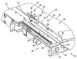
- FIG. 1is a front perspective view of a cable management panel having a locking arrangement according to the principles of the present disclosure, the cable management panel shown with a drawer of the panel in an opened, locked position;
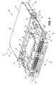
- FIG. 2is a partially exploded bottom view of a portion of the cable management panel of FIG. 1 ;
- FIG. 3is a perspective view of an activation arm of the locking arrangement of FIGS. 1 and 2 , shown in isolation;
- FIG. 4is a perspective view of a locking piece of the locking arrangement of FIGS. 1 and 2 , shown in isolation;
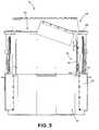
- FIG. 5is a bottom plan view of the cable management panel of FIG. 1 , shown with the drawer in an opened locked position;
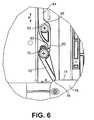
- FIG. 6is an enlarged view of a portion of the cable management panel of FIG. 5 , illustrating the locking arrangement in a locked position;
- FIG. 7is a bottom plan view of the cable management panel of FIG. 5 , shown with the drawer in an opened unlocked position;
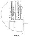
- FIG. 8is an enlarged view of a portion of the cable management panel of FIG. 7 , illustrating the locking arrangement in an unlocked position.
- the cable management panel 10includes a frame or chassis 12 having mounting brackets 14 . Further details of an example mounting bracket arrangement that can be used in accordance with the principles disclosed is described in U.S. Pat. No. 7,171,099, the disclosure of which is hereby incorporated by reference.
- the mounting brackets 14are used to mount the panel 10 to a telecommunication structure, such as a telecommunications rack, cabinet or other enclosure or framework.
- the chassis 12 of the cable management panel 10has a front 16 , opposite sides 18 , and a rear 20 .
- the sides 18include sidewalls 19 each having cable access openings 22 for cables entering or exiting the chassis 12 .
- the chassis 12further includes a top wall 23 and an opposite bottom wall 25 .
- the cable management panel 10also includes a drawer 26 having an interior region 24 .
- the drawer 26slides relative to the chassis 12 by way of a drawer slide assembly 28 located at each side 18 of the chassis 12 . Further details of slide assemblies that can be used in the present cable management panel are described in U.S. Pat. No. 7,171,099; which disclosure is incorporated herein by reference. In a closed position, the contents of the interior region 24 of the drawer 26 are enclosed and protected. In an open position, the interior region 24 can be accessed for cable or component installation, maintenance, or repair.
- the drawer 26 of the cable management panel 10has a front 33 , a rear 34 , a base 36 , and sides 38 , 39 .
- the rear 34 of the drawer 26is open.
- the sides 38 , 39 of the drawer 26are open.
- the open rear and open sidesallow for cable entry into and cable exit from the interior region 24 of the drawer 26 .
- Radius limiters 27are provided at the open sides 38 , 39 of the drawer for managing the exiting and entering cables at the sides during sliding movement of the drawer 26 .
- the radius limiters 27also protect the cables from damage by limiting cable bending beyond a minimum bend radius. Further details of example radius limiters and radius limiter assemblies that can be used in the present cable management panel are described in U.S. Pat. Nos. 6,438,310; 6,504,988; and 7,079,744; the disclosures of which are each incorporated herein by reference.
- the cable management panel 10can contain a variety of cable management elements.
- the cable management elementscan be mounted to the base 36 of the drawer 26 , or mounted on a tray or insert that drops into the interior region 24 of the drawer. Further details of an example drop-in tray that can be used in the present cable management panel 10 are described in U.S. Publication No. 2007/0031099, U.S. Provisional Application No. 61/072,184, filed Mar. 28, 2008, U.S. Provisional Application No. 61/126,672, filed May 5, 2008, and U.S. application Ser. No. 12/381,160, filed Mar. 6, 2009; which disclosures are incorporated herein by reference.
- the variety of cable management elements that the cable management panel 10 may containinclude cable retainers (e.g., 86 ), splice trays (e.g., 88 ), and adapter or connector holders to which fiber optic cables are terminated.
- Examples of other cable management elementsinclude other constructions, assemblies, and devices for storing cables or connecting the cables to other cables; and/or other fiber optic devices, such as attenuators, couplers, switches, wave division multiplexers (WDMs), and splitters/combiners.
- WDMswave division multiplexers
- splitters/combinerssplitters/combiners.
- the present cable management panel 10includes a first drawer locking arrangement 30 and a second drawer locking arrangement 40 (see also FIG. 2 ).
- the first drawer locking arrangement 30locks the drawer in the closed position; the second drawer locking arrangement 40 locks the drawer in the open position.
- the second open-drawer locking arrangement 40is designed to prevent inadvertent closing movement of the drawer 26 relative to the chassis 12 .
- closing movementis movement of the drawer in a rearward direction from the open position toward the closed position. It is noted that the drawer 26 can move beyond the open position to an extended open position in a forward direction. The user may move the drawer rearward from the extended open position to the open position; this rearward movement is not the closing movement that the second open-drawer locking arrangement prevents. Rather, the closing movement is movement of the drawer in a rearward direction from the open position toward the closed position, which can cause damage to cables and components when such movement inadvertently occurs during installation, repairs or maintenance.
- the user or technicianroutes cables into and out from the drawer, and/or internally routes cables to and from components contained within the drawer. Often times, the cables or components are pulled or pushed, forcing the drawer in a rearward direction. Closing movement of the drawer in the rearward direction can cause damage to cables and/or components not yet completely routed or secured.
- the presently disclosed open-drawer locking arrangement 40prevents the drawer 26 from closing and eliminates the occurrence of cable damage and/or component damage due to such inadvertent closing movement.
- each of the first drawer locking arrangement 30 and the second drawer locking arrangement 40is accessed from the front 33 of the drawer 26 .
- the first closed-drawer locking arrangement 30includes two front latches 31 located in a front panel 48 that defines the front 33 of the drawer 26 .
- Each front latch 31is located in the front panel 48 adjacent to one of the sides 38 , 39 of the drawer 26 .
- the latches 31engages a side hole 32 located at the side 18 of the chassis 12 to secure the drawer 26 in the closed position.
- the latches 31are accessed from the front 33 and moved toward one another to disengage from the side holes 32 of the chassis 12 . With the latches 31 disengaged from the side holes 32 of the chassis, the drawer 26 is free to slide open.
- the second open-drawer locking arrangement 40includes a linkage 42 located beneath of the drawer 26 on one of the sides 38 , 39 of the drawer. As will be described in greater detail hereinafter, the linkage is accessible from the front 33 of the drawer 26 . To unlock the drawer from the locked open position, the linkage 42 (i.e., 50 , see also FIG. 1 ) is accessed from the front panel 48 of the drawer. While the illustrated embodiment depicts the drawer having only a single open-drawer locking arrangement 40 , an open-drawer locking arrangement can be provided at each of the sides of the drawer.
- the linkage 42 of the second open-drawer locking arrangement 40generally includes a push arm or activation arm 44 and a locking piece 46 .
- the activation arm 44includes a first end 50 and a second end 52 .
- the first end 50is accessible from the front 33 of the drawer 26 .
- the first end 50extends through an aperture 54 ( FIG. 2 ) formed in the front panel 48 of the drawer 26 .
- the second end 52 of the activation arm 44is located to engage the locking piece 46 .
- the locking piece 46is located at the rear 34 of the drawer 26 .
- the activation arm 44accordingly has a length that extends from the front 33 of the drawer 26 to the rear 34 of the drawer.
- the activation arm 44has two apertures 56 , 58 ( FIG. 3 ) sized to receive fasteners 60 , 62 ( FIG. 2 ) that secure the activation arm 44 to a bottom or undersurface 64 of the drawer 26 .
- the undersurface 64 in the illustrated panel 10is defined by a horizontal side plate 66 (see also FIG. 1 ), which in turn defines the open side (e.g., both 38 , 39 ) of the drawer 26 .
- the apertures 56 , 58 of the activation arm 44each have an elongated slot shape.
- the elongated slot shape of the aperturespermits the activation arm 44 to travel in a linear forward-rearward direction (as represented by arrow A in FIGS. 5 and 6 ), yet still secures the activation arm 44 in relation to the drawer 26 .
- the locking piece 46also defines an aperture 68 ( FIG. 4 ) sized to receive a fastener 70 ( FIG. 2 ) that separately secures the locking piece 46 to the undersurface 64 of the drawer 26 .
- the aperture 68 of the locking piece 46is shaped and sized to permit the locking piece 46 to rotate (as represented by arrow B in FIG. 6 ), yet still secures the locking piece 46 in relation to the drawer 26 .
- the latches 31 of the first drawer locking arrangement 30In use, when the drawer 26 is in the closed position, the latches 31 of the first drawer locking arrangement 30 automatically engage the side holes 32 of the chassis 12 . This engagement locks the drawer 26 in the closed position. To open the drawer, the latches are disengaged from the side holes 32 and the drawer is slid to the open position.
- the activation arm 44 and the locking piece 46 of the second locking arrangement 40travel with the drawer 26 during sliding opening movement. Upon reaching the open position, the locking piece 46 automatically locks the drawer 26 in the open position. What is meant by “automatically” is that the locking piece 46 moves from a non-locking position to a locking position (see e.g., FIG. 6 ) without a technician having to manually move or manipulate the second open-drawer locking arrangement 40 .
- the second open-drawer locking arrangement 40includes a spring 72 ( FIG. 2 ) that biases the locking piece 46 toward the locking position shown in FIG. 6 .
- a distal end 78 of the locking piece 46engages a transverse edge 74 of a bottom plate 76 of the chassis 12 .
- the present open-drawer locking arrangement 40is arranged in relation to the drawer 26 and the chassis 12 such that a rear drawer wall is not required. In some applications, having a drawer with an open rear (e.g., 34 , FIG. 1 ) is desirable, for example, to permit cables to enter and exit the interior drawer region from the rear of the chassis 12 .
- the open-drawer locking arrangement 40locks the drawer in the open position without requiring a rear drawer wall.
- the useractivates the arm 44 ; i.e., pushes on the first end 50 of the activation arm 44 extending through the front panel 48 of the drawer 26 (see FIG. 1 ).
- Pushing the first end 50causes the activation arm 44 to travel in a linear direction A toward the locking piece 46 (i.e., the arm 44 slides or moves relative to fasteners 60 , 62 by way of the slot-shaped apertures 56 , 58 ).
- a nose or projection 80 of the arm 44seats within a shoulder or notch 82 formed in the locking piece 46 .
- the projection 80 of the arm 44seats within the notch 82 of the locking piece 46 causing the locking piece to rotate from the locking position ( FIG. 6 ) to the non-locking position ( FIG. 8 ).
- the drawer 26is unlocked and free to close.
- the locking piece 46generally slides along a longitudinal edge 84 of the bottom plate 76 of the chassis 12 as the drawer 26 closes.
- the spring 72is biased such that when the drawer is again opened, the locking piece 46 automatically rotates into engagement with the transverse edge 74 of the chassis 12 to lock the drawer 26 in the open position.
- the biasing action of the spring 72 and the rotation of the locking piece 46cause the activation arm 44 to slide or move relative to fasteners 60 , 62 , by way of the slot-shaped apertures 56 , 58 , toward the front panel 48 .
- the first end 50 of the activation armis thereby in position at the front panel 48 for activation or access at the front 33 of the drawer 26 .
Landscapes
- Engineering & Computer Science (AREA)
- Computer Networks & Wireless Communication (AREA)
- Physics & Mathematics (AREA)
- General Physics & Mathematics (AREA)
- Optics & Photonics (AREA)
- Drawers Of Furniture (AREA)
Abstract
Description
Claims (18)
Priority Applications (2)
| Application Number | Priority Date | Filing Date | Title |
|---|---|---|---|
| US12/381,155US8041175B2 (en) | 2008-05-05 | 2009-03-06 | Front-access locking arrangement for sliding drawer |
| US13/275,042US8483536B2 (en) | 2008-05-05 | 2011-10-17 | Front-access locking arrangement for sliding drawer |
Applications Claiming Priority (2)
| Application Number | Priority Date | Filing Date | Title |
|---|---|---|---|
| US12665308P | 2008-05-05 | 2008-05-05 | |
| US12/381,155US8041175B2 (en) | 2008-05-05 | 2009-03-06 | Front-access locking arrangement for sliding drawer |
Related Child Applications (1)
| Application Number | Title | Priority Date | Filing Date |
|---|---|---|---|
| US13/275,042ContinuationUS8483536B2 (en) | 2008-05-05 | 2011-10-17 | Front-access locking arrangement for sliding drawer |
Publications (2)
| Publication Number | Publication Date |
|---|---|
| US20090274429A1 US20090274429A1 (en) | 2009-11-05 |
| US8041175B2true US8041175B2 (en) | 2011-10-18 |
Family
ID=41257144
Family Applications (2)
| Application Number | Title | Priority Date | Filing Date |
|---|---|---|---|
| US12/381,155Expired - Fee RelatedUS8041175B2 (en) | 2008-05-05 | 2009-03-06 | Front-access locking arrangement for sliding drawer |
| US13/275,042Expired - Fee RelatedUS8483536B2 (en) | 2008-05-05 | 2011-10-17 | Front-access locking arrangement for sliding drawer |
Family Applications After (1)
| Application Number | Title | Priority Date | Filing Date |
|---|---|---|---|
| US13/275,042Expired - Fee RelatedUS8483536B2 (en) | 2008-05-05 | 2011-10-17 | Front-access locking arrangement for sliding drawer |
Country Status (1)
| Country | Link |
|---|---|
| US (2) | US8041175B2 (en) |
Cited By (16)
| Publication number | Priority date | Publication date | Assignee | Title |
|---|---|---|---|---|
| US9541726B2 (en) | 2013-04-24 | 2017-01-10 | Adc Czech Republic, S.R.O. | Optical fiber distribution system |
| US9568699B2 (en) | 2013-01-29 | 2017-02-14 | CommScope Connectivity Belgium BVBA | Optical fiber distribution system |
| US10261281B2 (en) | 2015-04-03 | 2019-04-16 | CommScope Connectivity Belgium BVBA | Telecommunications distribution elements |
| US10409020B2 (en) | 2013-04-24 | 2019-09-10 | CommScope Connectivity Belgium BVBA | Universal mounting mechanism for mounting a telecommunications chassis to a telecommunciations fixture |
| US20210337965A1 (en)* | 2019-01-29 | 2021-11-04 | Julius Blum Gmbh | Locking device for releasably locking a withdrawable furniture part |
| US11409067B2 (en) | 2018-08-31 | 2022-08-09 | CommScope Connectivity Belgium BVBA | Frame assemblies for optical fiber distribution elements |
| US11448845B2 (en) | 2018-08-31 | 2022-09-20 | CommScope Connectivity Belgium BVBA | Frame assemblies for optical fiber distribution elements |
| US11448844B2 (en) | 2018-08-31 | 2022-09-20 | CommScope Connectivity Belgium BVBA | Frame assemblies for optical fiber distribution elements |
| US11448831B2 (en) | 2018-08-31 | 2022-09-20 | CommScope Connectivity Belgium BVBA | Frame assemblies for optical fiber distribution elements |
| US11635578B2 (en) | 2018-04-17 | 2023-04-25 | CommScope Connectivity Belgium BVBA | Telecommunications distribution elements |
| US11852882B2 (en) | 2018-02-28 | 2023-12-26 | Commscope Technologies Llc | Packaging assembly for telecommunications equipment |
| US11947177B2 (en) | 2019-01-25 | 2024-04-02 | CommScope Connectivity Belgium BVBA | Frame assemblies for optical fiber distribution elements |
| US12007615B2 (en) | 2018-10-23 | 2024-06-11 | CommScope Connectivity Belgium BVBA | Frame assemblies for optical fiber distribution elements |
| US12050358B2 (en) | 2018-08-31 | 2024-07-30 | CommScope Connectivity Belgium BVBA | Frame assemblies for optical fiber distribution elements |
| US12099246B2 (en) | 2020-01-24 | 2024-09-24 | CommScope Connectivity Belgium BVBA | Telecommunications distribution elements |
| US12174443B2 (en) | 2020-01-22 | 2024-12-24 | CommScope Connectivity Belgium BVBA | Cable termination units for optical fiber distribution elements |
Families Citing this family (64)
| Publication number | Priority date | Publication date | Assignee | Title |
|---|---|---|---|---|
| US11294136B2 (en) | 2008-08-29 | 2022-04-05 | Corning Optical Communications LLC | High density and bandwidth fiber optic apparatuses and related equipment and methods |
| US8452148B2 (en) | 2008-08-29 | 2013-05-28 | Corning Cable Systems Llc | Independently translatable modules and fiber optic equipment trays in fiber optic equipment |
| US7856166B2 (en) | 2008-09-02 | 2010-12-21 | Corning Cable Systems Llc | High-density patch-panel assemblies for optical fiber telecommunications |
| CN102209921B (en) | 2008-10-09 | 2015-11-25 | 康宁光缆系统有限公司 | There is the fibre-optic terminus supported from the adapter panel of the input and output optical fiber of optical splitters |
| US8879882B2 (en) | 2008-10-27 | 2014-11-04 | Corning Cable Systems Llc | Variably configurable and modular local convergence point |
| EP2221932B1 (en) | 2009-02-24 | 2011-11-16 | CCS Technology Inc. | Holding device for a cable or an assembly for use with a cable |
| US8699838B2 (en) | 2009-05-14 | 2014-04-15 | Ccs Technology, Inc. | Fiber optic furcation module |
| US9075216B2 (en) | 2009-05-21 | 2015-07-07 | Corning Cable Systems Llc | Fiber optic housings configured to accommodate fiber optic modules/cassettes and fiber optic panels, and related components and methods |
| US8538226B2 (en) | 2009-05-21 | 2013-09-17 | Corning Cable Systems Llc | Fiber optic equipment guides and rails configured with stopping position(s), and related equipment and methods |
| WO2010148325A1 (en) | 2009-06-19 | 2010-12-23 | Corning Cable Systems Llc | High fiber optic cable packing density apparatus |
| US8712206B2 (en) | 2009-06-19 | 2014-04-29 | Corning Cable Systems Llc | High-density fiber optic modules and module housings and related equipment |
| EP2443497B1 (en) | 2009-06-19 | 2020-03-04 | Corning Cable Systems LLC | High density and bandwidth fiber optic apparatus |
| US8625950B2 (en) | 2009-12-18 | 2014-01-07 | Corning Cable Systems Llc | Rotary locking apparatus for fiber optic equipment trays and related methods |
| US8992099B2 (en) | 2010-02-04 | 2015-03-31 | Corning Cable Systems Llc | Optical interface cards, assemblies, and related methods, suited for installation and use in antenna system equipment |
| US8913866B2 (en) | 2010-03-26 | 2014-12-16 | Corning Cable Systems Llc | Movable adapter panel |
| CA2796221C (en) | 2010-04-16 | 2018-02-13 | Ccs Technology, Inc. | Sealing and strain relief device for data cables |
| EP2381284B1 (en) | 2010-04-23 | 2014-12-31 | CCS Technology Inc. | Under floor fiber optic distribution device |
| CN102985859A (en)* | 2010-04-23 | 2013-03-20 | Ccs技术公司 | Removable fiber optic splice tray |
| US9720195B2 (en) | 2010-04-30 | 2017-08-01 | Corning Optical Communications LLC | Apparatuses and related components and methods for attachment and release of fiber optic housings to and from an equipment rack |
| US8660397B2 (en) | 2010-04-30 | 2014-02-25 | Corning Cable Systems Llc | Multi-layer module |
| US9632270B2 (en) | 2010-04-30 | 2017-04-25 | Corning Optical Communications LLC | Fiber optic housings configured for tool-less assembly, and related components and methods |
| US8879881B2 (en) | 2010-04-30 | 2014-11-04 | Corning Cable Systems Llc | Rotatable routing guide and assembly |
| US9075217B2 (en) | 2010-04-30 | 2015-07-07 | Corning Cable Systems Llc | Apparatuses and related components and methods for expanding capacity of fiber optic housings |
| US8705926B2 (en) | 2010-04-30 | 2014-04-22 | Corning Optical Communications LLC | Fiber optic housings having a removable top, and related components and methods |
| US9519118B2 (en) | 2010-04-30 | 2016-12-13 | Corning Optical Communications LLC | Removable fiber management sections for fiber optic housings, and related components and methods |
| US8718436B2 (en) | 2010-08-30 | 2014-05-06 | Corning Cable Systems Llc | Methods, apparatuses for providing secure fiber optic connections |
| WO2012054454A2 (en) | 2010-10-19 | 2012-04-26 | Corning Cable Systems Llc | Transition box for multiple dwelling unit fiber optic distribution network |
| US9279951B2 (en) | 2010-10-27 | 2016-03-08 | Corning Cable Systems Llc | Fiber optic module for limited space applications having a partially sealed module sub-assembly |
| US9116324B2 (en) | 2010-10-29 | 2015-08-25 | Corning Cable Systems Llc | Stacked fiber optic modules and fiber optic equipment configured to support stacked fiber optic modules |
| US8662760B2 (en) | 2010-10-29 | 2014-03-04 | Corning Cable Systems Llc | Fiber optic connector employing optical fiber guide member |
| CA2819235C (en) | 2010-11-30 | 2018-01-16 | Corning Cable Systems Llc | Fiber device holder and strain relief device |
| WO2012106510A2 (en) | 2011-02-02 | 2012-08-09 | Corning Cable Systems Llc | Dense fiber optic connector assemblies and related connectors and cables suitable for establishing optical connections for optical backplanes in equipment racks |
| US9008485B2 (en) | 2011-05-09 | 2015-04-14 | Corning Cable Systems Llc | Attachment mechanisms employed to attach a rear housing section to a fiber optic housing, and related assemblies and methods |
| AU2012275598A1 (en) | 2011-06-30 | 2014-01-16 | Corning Optical Communications LLC | Fiber optic equipment assemblies employing non-U-width-sized housings and related methods |
| US10314594B2 (en) | 2012-12-14 | 2019-06-11 | Corquest Medical, Inc. | Assembly and method for left atrial appendage occlusion |
| US10813630B2 (en) | 2011-08-09 | 2020-10-27 | Corquest Medical, Inc. | Closure system for atrial wall |
| US10307167B2 (en) | 2012-12-14 | 2019-06-04 | Corquest Medical, Inc. | Assembly and method for left atrial appendage occlusion |
| US8953924B2 (en) | 2011-09-02 | 2015-02-10 | Corning Cable Systems Llc | Removable strain relief brackets for securing fiber optic cables and/or optical fibers to fiber optic equipment, and related assemblies and methods |
| US9038832B2 (en) | 2011-11-30 | 2015-05-26 | Corning Cable Systems Llc | Adapter panel support assembly |
| US9219546B2 (en) | 2011-12-12 | 2015-12-22 | Corning Optical Communications LLC | Extremely high frequency (EHF) distributed antenna systems, and related components and methods |
| US10110307B2 (en) | 2012-03-02 | 2018-10-23 | Corning Optical Communications LLC | Optical network units (ONUs) for high bandwidth connectivity, and related components and methods |
| US9004778B2 (en) | 2012-06-29 | 2015-04-14 | Corning Cable Systems Llc | Indexable optical fiber connectors and optical fiber connector arrays |
| US9250409B2 (en) | 2012-07-02 | 2016-02-02 | Corning Cable Systems Llc | Fiber-optic-module trays and drawers for fiber-optic equipment |
| US9049500B2 (en) | 2012-08-31 | 2015-06-02 | Corning Cable Systems Llc | Fiber optic terminals, systems, and methods for network service management |
| US8909019B2 (en) | 2012-10-11 | 2014-12-09 | Ccs Technology, Inc. | System comprising a plurality of distribution devices and distribution device |
| ES2551077T3 (en) | 2012-10-26 | 2015-11-16 | Ccs Technology, Inc. | Fiber optic management unit and fiber optic distribution device |
| US20140142689A1 (en) | 2012-11-21 | 2014-05-22 | Didier De Canniere | Device and method of treating heart valve malfunction |
| US20140247541A1 (en)* | 2013-02-26 | 2014-09-04 | Realm Communications Group, Inc. | Telecom cabinet dual tray slider |
| US8985862B2 (en) | 2013-02-28 | 2015-03-24 | Corning Cable Systems Llc | High-density multi-fiber adapter housings |
| US9566443B2 (en) | 2013-11-26 | 2017-02-14 | Corquest Medical, Inc. | System for treating heart valve malfunction including mitral regurgitation |
| EP2950282A1 (en)* | 2014-05-30 | 2015-12-02 | Cleveron Ltd. | Modular parcel terminal and the method for sending parcels |
| US10842626B2 (en) | 2014-12-09 | 2020-11-24 | Didier De Canniere | Intracardiac device to correct mitral regurgitation |
| US10264698B2 (en)* | 2017-08-25 | 2019-04-16 | Facebook, Inc. | Systems and methods for mounting assembly pull-handles |
| US10687435B2 (en) | 2017-08-28 | 2020-06-16 | Facebook, Inc. | Apparatus, system, and method for enabling multiple storage-system configurations |
| US10349554B2 (en) | 2017-08-29 | 2019-07-09 | Facebook, Inc. | Apparatus, system, and method for directing air in a storage-system chassis |
| US10736228B2 (en) | 2017-08-31 | 2020-08-04 | Facebook, Inc. | Removeable drive-plane apparatus, system, and method |
| US10372360B2 (en) | 2017-09-01 | 2019-08-06 | Facebook, Inc. | Apparatus, system, and method for reconfigurable media-agnostic storage |
| US10537035B2 (en) | 2017-09-06 | 2020-01-14 | Facebook, Inc. | Apparatus, system, and method for securing hard drives in a storage chassis |
| US10429911B2 (en) | 2017-09-07 | 2019-10-01 | Facebook, Inc. | Apparatus, system, and method for detecting device types of storage devices |
| US10558248B2 (en) | 2017-09-09 | 2020-02-11 | Facebook, Inc. | Apparatus, system, and method for indicating the status of and securing hard drives |
| US10588238B2 (en) | 2017-09-18 | 2020-03-10 | Facebook, Inc. | Apparatus, system, and method for partitioning a storage-system chassis |
| US10178791B1 (en) | 2017-09-23 | 2019-01-08 | Facebook, Inc. | Apparatus, system, and method for securing computing components to printed circuit boards |
| US10240615B1 (en) | 2017-09-23 | 2019-03-26 | Facebook, Inc. | Apparatus, system, and method for dampening vibrations generated by exhaust fans |
| US10757831B2 (en) | 2017-09-26 | 2020-08-25 | Facebook, Inc. | Apparatus, system, and method for reconfiguring air flow through a chassis |
Citations (16)
| Publication number | Priority date | Publication date | Assignee | Title |
|---|---|---|---|---|
| US2517175A (en)* | 1947-01-23 | 1950-08-01 | Mosler Safe Co | Cash drawer or the like |
| US3589783A (en) | 1968-10-31 | 1971-06-29 | Lyon Metal Products Inc | Drawer-locking system |
| US3651986A (en) | 1970-07-29 | 1972-03-28 | Docutel Corp | Credit card automatic currency dispenser |
| US3782800A (en) | 1972-06-22 | 1974-01-01 | Stanley Works | Latch mechanism |
| US5141266A (en) | 1990-03-05 | 1992-08-25 | Cleveland Hardware & Forging Company | Sliding door rotary latch system |
| US5723850A (en) | 1996-07-26 | 1998-03-03 | Loyal Manufacturing Corporation | Cash drawer assembly |
| US5802892A (en) | 1996-05-08 | 1998-09-08 | Metro Industries, Inc. | Storage system including multifunction lock assembly utilizing lock latch mechanism and lock latch extension mechanism |
| US6438310B1 (en) | 2000-01-24 | 2002-08-20 | Adc Telecommunications, Inc. | Cable management panel with sliding drawer |
| US6435587B1 (en) | 2001-01-05 | 2002-08-20 | Johnson Controls Technology Company | Console |
| US20020124779A1 (en) | 2000-12-22 | 2002-09-12 | Perkins Daniel D. | Hidden drawer safe |
| US6504988B1 (en) | 2000-01-24 | 2003-01-07 | Adc Telecommunications, Inc. | Cable management panel with sliding drawer |
| US20050025444A1 (en) | 2003-07-31 | 2005-02-03 | Barnes Kathleen M. | Slide arrangement for cable drawer |
| US7079744B2 (en) | 2001-07-06 | 2006-07-18 | Adc Telecommunications, Inc. | Cable management panel with sliding drawer and methods |
| US20070031099A1 (en) | 2005-08-02 | 2007-02-08 | Herzog Daniel J | Cable management panel with rear entry |
| US20080085092A1 (en) | 2006-10-04 | 2008-04-10 | Barnes Kathleen M | Slide arrangement for cable drawer |
| US20080304803A1 (en) | 2007-06-06 | 2008-12-11 | Adc Telecommunications, Inc. | Rear drawer latch |
Family Cites Families (1)
| Publication number | Priority date | Publication date | Assignee | Title |
|---|---|---|---|---|
| US7764859B2 (en) | 2008-03-28 | 2010-07-27 | Adc Telecommunications, Inc. | Universal cable management panel |
- 2009
- 2009-03-06USUS12/381,155patent/US8041175B2/ennot_activeExpired - Fee Related
- 2011
- 2011-10-17USUS13/275,042patent/US8483536B2/ennot_activeExpired - Fee Related
Patent Citations (17)
| Publication number | Priority date | Publication date | Assignee | Title |
|---|---|---|---|---|
| US2517175A (en)* | 1947-01-23 | 1950-08-01 | Mosler Safe Co | Cash drawer or the like |
| US3589783A (en) | 1968-10-31 | 1971-06-29 | Lyon Metal Products Inc | Drawer-locking system |
| US3651986A (en) | 1970-07-29 | 1972-03-28 | Docutel Corp | Credit card automatic currency dispenser |
| US3782800A (en) | 1972-06-22 | 1974-01-01 | Stanley Works | Latch mechanism |
| US5141266A (en) | 1990-03-05 | 1992-08-25 | Cleveland Hardware & Forging Company | Sliding door rotary latch system |
| US5802892A (en) | 1996-05-08 | 1998-09-08 | Metro Industries, Inc. | Storage system including multifunction lock assembly utilizing lock latch mechanism and lock latch extension mechanism |
| US5723850A (en) | 1996-07-26 | 1998-03-03 | Loyal Manufacturing Corporation | Cash drawer assembly |
| US6504988B1 (en) | 2000-01-24 | 2003-01-07 | Adc Telecommunications, Inc. | Cable management panel with sliding drawer |
| US6438310B1 (en) | 2000-01-24 | 2002-08-20 | Adc Telecommunications, Inc. | Cable management panel with sliding drawer |
| US20020124779A1 (en) | 2000-12-22 | 2002-09-12 | Perkins Daniel D. | Hidden drawer safe |
| US6435587B1 (en) | 2001-01-05 | 2002-08-20 | Johnson Controls Technology Company | Console |
| US7079744B2 (en) | 2001-07-06 | 2006-07-18 | Adc Telecommunications, Inc. | Cable management panel with sliding drawer and methods |
| US20050025444A1 (en) | 2003-07-31 | 2005-02-03 | Barnes Kathleen M. | Slide arrangement for cable drawer |
| US7171099B2 (en) | 2003-07-31 | 2007-01-30 | Adc Telecommunications, Inc. | Slide arrangement for cable drawer |
| US20070031099A1 (en) | 2005-08-02 | 2007-02-08 | Herzog Daniel J | Cable management panel with rear entry |
| US20080085092A1 (en) | 2006-10-04 | 2008-04-10 | Barnes Kathleen M | Slide arrangement for cable drawer |
| US20080304803A1 (en) | 2007-06-06 | 2008-12-11 | Adc Telecommunications, Inc. | Rear drawer latch |
Non-Patent Citations (3)
| Title |
|---|
| U.S. Appl. No. 12/381,160, filed Mar. 6, 2009, Krampotich et al. |
| U.S. Appl. No. 61/072,184, filed Mar. 28, 2008, Krampotich; 29 pages. |
| U.S. Appl. No. 61/126,672, filed May 5, 2008, Krampotich et al.; 33 pages. |
Cited By (38)
| Publication number | Priority date | Publication date | Assignee | Title |
|---|---|---|---|---|
| US11320618B2 (en) | 2013-01-29 | 2022-05-03 | CommScope Connectivity Belgium BVBA | Optical fiber distribution system |
| US9568699B2 (en) | 2013-01-29 | 2017-02-14 | CommScope Connectivity Belgium BVBA | Optical fiber distribution system |
| US12422640B2 (en) | 2013-01-29 | 2025-09-23 | CommScope Connectivity Belgium BVBA | Optical fiber distribution system |
| US10126515B2 (en) | 2013-01-29 | 2018-11-13 | CommScope Connectivity Belgium BVBA | Optical fiber distribution system |
| US12019300B2 (en) | 2013-01-29 | 2024-06-25 | CommScope Connectivity Belgium BVBA | Optical fiber distribution system |
| US11614594B2 (en) | 2013-01-29 | 2023-03-28 | CommScope Connectivity Belgium BVBA | Optical fiber distribution system |
| US10732373B2 (en) | 2013-01-29 | 2020-08-04 | CommScope Connectivity Belgium BVBA | Optical fiber distribution system |
| US11002936B2 (en) | 2013-04-24 | 2021-05-11 | CommScope Connectivity Belgium BVBA | Optical fiber distribution system |
| US9541726B2 (en) | 2013-04-24 | 2017-01-10 | Adc Czech Republic, S.R.O. | Optical fiber distribution system |
| US11092766B2 (en) | 2013-04-24 | 2021-08-17 | CommScope Connectivity Belgium BVBA | Universal mounting mechanism for mounting a telecommunications chassis to a telecommunications fixture |
| US10107984B2 (en) | 2013-04-24 | 2018-10-23 | CommScope Connectivity Belgium BVBA | Optical fiber distribution system |
| US10746950B2 (en) | 2013-04-24 | 2020-08-18 | CommScope Connectivity Belgium BVBA | Optical fiber distribution system |
| US11988887B2 (en) | 2013-04-24 | 2024-05-21 | CommScope Connectivity Belgium BVBA | Optical fiber distribution system |
| US11982855B2 (en) | 2013-04-24 | 2024-05-14 | CommScope Connectivity Belgium BVBA | Universal mounting mechanism for mounting a telecommunications chassis to a telecommunications fixture |
| US11579395B2 (en) | 2013-04-24 | 2023-02-14 | CommScope Connectivity Belgium BVBA | Optical fiber distribution system |
| US10409020B2 (en) | 2013-04-24 | 2019-09-10 | CommScope Connectivity Belgium BVBA | Universal mounting mechanism for mounting a telecommunications chassis to a telecommunciations fixture |
| US10908375B2 (en) | 2015-04-03 | 2021-02-02 | CommScope Connectivity Belgium BVBA | Telecommunications distribution elements |
| US12055779B2 (en) | 2015-04-03 | 2024-08-06 | CommScope Connectivity Belgium BVBA | Telecommunications distribution elements |
| US10261281B2 (en) | 2015-04-03 | 2019-04-16 | CommScope Connectivity Belgium BVBA | Telecommunications distribution elements |
| US11592639B2 (en) | 2015-04-03 | 2023-02-28 | CommScope Connectivity Belgium BVBA | Telecommunications distribution elements |
| US11852882B2 (en) | 2018-02-28 | 2023-12-26 | Commscope Technologies Llc | Packaging assembly for telecommunications equipment |
| US11635578B2 (en) | 2018-04-17 | 2023-04-25 | CommScope Connectivity Belgium BVBA | Telecommunications distribution elements |
| US11409067B2 (en) | 2018-08-31 | 2022-08-09 | CommScope Connectivity Belgium BVBA | Frame assemblies for optical fiber distribution elements |
| US12189188B2 (en) | 2018-08-31 | 2025-01-07 | CommScope Connectivity Belgium BVBA | Frame assemblies for optical fiber distribution elements |
| US11448831B2 (en) | 2018-08-31 | 2022-09-20 | CommScope Connectivity Belgium BVBA | Frame assemblies for optical fiber distribution elements |
| US11448844B2 (en) | 2018-08-31 | 2022-09-20 | CommScope Connectivity Belgium BVBA | Frame assemblies for optical fiber distribution elements |
| US12050358B2 (en) | 2018-08-31 | 2024-07-30 | CommScope Connectivity Belgium BVBA | Frame assemblies for optical fiber distribution elements |
| US11448845B2 (en) | 2018-08-31 | 2022-09-20 | CommScope Connectivity Belgium BVBA | Frame assemblies for optical fiber distribution elements |
| US12306451B2 (en) | 2018-08-31 | 2025-05-20 | CommScope Connectivity Belgium BVBA | Frame assemblies for optical fiber distribution elements |
| US12197026B2 (en) | 2018-08-31 | 2025-01-14 | CommScope Connectivity Belgium BVBA | Frame assemblies for optical fiber distribution elements |
| US12197025B2 (en) | 2018-08-31 | 2025-01-14 | CommScope Connectivity Belgium BVBA | Frame assemblies for optical fiber distribution elements |
| US12197027B2 (en) | 2018-08-31 | 2025-01-14 | CommScope Connectivity Belgium BVBA | Frame assemblies for optical fiber distribution elements |
| US12007615B2 (en) | 2018-10-23 | 2024-06-11 | CommScope Connectivity Belgium BVBA | Frame assemblies for optical fiber distribution elements |
| US11947177B2 (en) | 2019-01-25 | 2024-04-02 | CommScope Connectivity Belgium BVBA | Frame assemblies for optical fiber distribution elements |
| US11766119B2 (en)* | 2019-01-29 | 2023-09-26 | Julius Blum Gmbh | Locking device for releasably locking a withdrawable furniture part |
| US20210337965A1 (en)* | 2019-01-29 | 2021-11-04 | Julius Blum Gmbh | Locking device for releasably locking a withdrawable furniture part |
| US12174443B2 (en) | 2020-01-22 | 2024-12-24 | CommScope Connectivity Belgium BVBA | Cable termination units for optical fiber distribution elements |
| US12099246B2 (en) | 2020-01-24 | 2024-09-24 | CommScope Connectivity Belgium BVBA | Telecommunications distribution elements |
Also Published As
| Publication number | Publication date |
|---|---|
| US20120275754A1 (en) | 2012-11-01 |
| US20090274429A1 (en) | 2009-11-05 |
| US8483536B2 (en) | 2013-07-09 |
Similar Documents
| Publication | Publication Date | Title |
|---|---|---|
| US8041175B2 (en) | Front-access locking arrangement for sliding drawer | |
| US8229268B2 (en) | Rear latch arrangement for sliding drawer | |
| US7567744B2 (en) | Rear drawer latch | |
| US7437049B2 (en) | Cable management drawer with access panel | |
| US7418182B2 (en) | Cable management drawer with access panel | |
| US8452149B2 (en) | Drawer arrangement with rack and pinion | |
| US8155494B2 (en) | Universal cable management panel | |
| US6748155B2 (en) | Fiber management drawer and sliding cable slack limiter | |
| US8280216B2 (en) | Fiber optic equipment supporting moveable fiber optic equipment tray(s) and module(s), and related equipment and methods | |
| US20040011750A1 (en) | Fiber management drawer and patch panel | |
| CN102439498B (en) | Be configured with the fiber plant guiding piece of one or more stop position and track and relevant device and method | |
| AU2017204601B2 (en) | Fiber optic equipment supporting moveable fiber optic equipment tray(s) and module(s), and related equipment and methods | |
| HK1151938B (en) | Rear latch arrangement for sliding drawer | |
| AU2015203530B2 (en) | Fiber optic equipment guides and rails configured with stopping position(s), and related equipment and methods |
Legal Events
| Date | Code | Title | Description |
|---|---|---|---|
| AS | Assignment | Owner name:ADC TELECOMMUNICATIONS, INC., MINNESOTA Free format text:ASSIGNMENT OF ASSIGNORS INTEREST;ASSIGNORS:KRAMPOTICH, DENNIS;KOSTECKA, RYAN;REEL/FRAME:022640/0270 Effective date:20090422 | |
| STCF | Information on status: patent grant | Free format text:PATENTED CASE | |
| FPAY | Fee payment | Year of fee payment:4 | |
| AS | Assignment | Owner name:TYCO ELECTRONICS SERVICES GMBH, SWITZERLAND Free format text:ASSIGNMENT OF ASSIGNORS INTEREST;ASSIGNOR:ADC TELECOMMUNICATIONS, INC.;REEL/FRAME:036060/0174 Effective date:20110930 | |
| AS | Assignment | Owner name:COMMSCOPE EMEA LIMITED, IRELAND Free format text:ASSIGNMENT OF ASSIGNORS INTEREST;ASSIGNOR:TYCO ELECTRONICS SERVICES GMBH;REEL/FRAME:036956/0001 Effective date:20150828 | |
| AS | Assignment | Owner name:COMMSCOPE TECHNOLOGIES LLC, NORTH CAROLINA Free format text:ASSIGNMENT OF ASSIGNORS INTEREST;ASSIGNOR:COMMSCOPE EMEA LIMITED;REEL/FRAME:037012/0001 Effective date:20150828 | |
| AS | Assignment | Owner name:JPMORGAN CHASE BANK, N.A., AS COLLATERAL AGENT, ILLINOIS Free format text:PATENT SECURITY AGREEMENT (TERM);ASSIGNOR:COMMSCOPE TECHNOLOGIES LLC;REEL/FRAME:037513/0709 Effective date:20151220 Owner name:JPMORGAN CHASE BANK, N.A., AS COLLATERAL AGENT, ILLINOIS Free format text:PATENT SECURITY AGREEMENT (ABL);ASSIGNOR:COMMSCOPE TECHNOLOGIES LLC;REEL/FRAME:037514/0196 Effective date:20151220 Owner name:JPMORGAN CHASE BANK, N.A., AS COLLATERAL AGENT, IL Free format text:PATENT SECURITY AGREEMENT (TERM);ASSIGNOR:COMMSCOPE TECHNOLOGIES LLC;REEL/FRAME:037513/0709 Effective date:20151220 Owner name:JPMORGAN CHASE BANK, N.A., AS COLLATERAL AGENT, IL Free format text:PATENT SECURITY AGREEMENT (ABL);ASSIGNOR:COMMSCOPE TECHNOLOGIES LLC;REEL/FRAME:037514/0196 Effective date:20151220 | |
| AS | Assignment | Owner name:ALLEN TELECOM LLC, ILLINOIS Free format text:RELEASE BY SECURED PARTY;ASSIGNOR:JPMORGAN CHASE BANK, N.A.;REEL/FRAME:048840/0001 Effective date:20190404 Owner name:COMMSCOPE, INC. OF NORTH CAROLINA, NORTH CAROLINA Free format text:RELEASE BY SECURED PARTY;ASSIGNOR:JPMORGAN CHASE BANK, N.A.;REEL/FRAME:048840/0001 Effective date:20190404 Owner name:ANDREW LLC, NORTH CAROLINA Free format text:RELEASE BY SECURED PARTY;ASSIGNOR:JPMORGAN CHASE BANK, N.A.;REEL/FRAME:048840/0001 Effective date:20190404 Owner name:REDWOOD SYSTEMS, INC., NORTH CAROLINA Free format text:RELEASE BY SECURED PARTY;ASSIGNOR:JPMORGAN CHASE BANK, N.A.;REEL/FRAME:048840/0001 Effective date:20190404 Owner name:COMMSCOPE TECHNOLOGIES LLC, NORTH CAROLINA Free format text:RELEASE BY SECURED PARTY;ASSIGNOR:JPMORGAN CHASE BANK, N.A.;REEL/FRAME:048840/0001 Effective date:20190404 Owner name:REDWOOD SYSTEMS, INC., NORTH CAROLINA Free format text:RELEASE BY SECURED PARTY;ASSIGNOR:JPMORGAN CHASE BANK, N.A.;REEL/FRAME:049260/0001 Effective date:20190404 Owner name:COMMSCOPE TECHNOLOGIES LLC, NORTH CAROLINA Free format text:RELEASE BY SECURED PARTY;ASSIGNOR:JPMORGAN CHASE BANK, N.A.;REEL/FRAME:049260/0001 Effective date:20190404 Owner name:ALLEN TELECOM LLC, ILLINOIS Free format text:RELEASE BY SECURED PARTY;ASSIGNOR:JPMORGAN CHASE BANK, N.A.;REEL/FRAME:049260/0001 Effective date:20190404 Owner name:ANDREW LLC, NORTH CAROLINA Free format text:RELEASE BY SECURED PARTY;ASSIGNOR:JPMORGAN CHASE BANK, N.A.;REEL/FRAME:049260/0001 Effective date:20190404 Owner name:COMMSCOPE, INC. OF NORTH CAROLINA, NORTH CAROLINA Free format text:RELEASE BY SECURED PARTY;ASSIGNOR:JPMORGAN CHASE BANK, N.A.;REEL/FRAME:049260/0001 Effective date:20190404 | |
| FEPP | Fee payment procedure | Free format text:MAINTENANCE FEE REMINDER MAILED (ORIGINAL EVENT CODE: REM.); ENTITY STATUS OF PATENT OWNER: LARGE ENTITY | |
| AS | Assignment | Owner name:WILMINGTON TRUST, NATIONAL ASSOCIATION, AS COLLATE Free format text:PATENT SECURITY AGREEMENT;ASSIGNOR:COMMSCOPE TECHNOLOGIES LLC;REEL/FRAME:049892/0051 Effective date:20190404 Owner name:JPMORGAN CHASE BANK, N.A., NEW YORK Free format text:ABL SECURITY AGREEMENT;ASSIGNORS:COMMSCOPE, INC. OF NORTH CAROLINA;COMMSCOPE TECHNOLOGIES LLC;ARRIS ENTERPRISES LLC;AND OTHERS;REEL/FRAME:049892/0396 Effective date:20190404 Owner name:JPMORGAN CHASE BANK, N.A., NEW YORK Free format text:TERM LOAN SECURITY AGREEMENT;ASSIGNORS:COMMSCOPE, INC. OF NORTH CAROLINA;COMMSCOPE TECHNOLOGIES LLC;ARRIS ENTERPRISES LLC;AND OTHERS;REEL/FRAME:049905/0504 Effective date:20190404 Owner name:WILMINGTON TRUST, NATIONAL ASSOCIATION, AS COLLATERAL AGENT, CONNECTICUT Free format text:PATENT SECURITY AGREEMENT;ASSIGNOR:COMMSCOPE TECHNOLOGIES LLC;REEL/FRAME:049892/0051 Effective date:20190404 | |
| LAPS | Lapse for failure to pay maintenance fees | Free format text:PATENT EXPIRED FOR FAILURE TO PAY MAINTENANCE FEES (ORIGINAL EVENT CODE: EXP.); ENTITY STATUS OF PATENT OWNER: LARGE ENTITY | |
| STCH | Information on status: patent discontinuation | Free format text:PATENT EXPIRED DUE TO NONPAYMENT OF MAINTENANCE FEES UNDER 37 CFR 1.362 | |
| FP | Lapsed due to failure to pay maintenance fee | Effective date:20191018 | |
| AS | Assignment | Owner name:BISON PATENT LICENSING, LLC, GEORGIA Free format text:ASSIGNMENT OF ASSIGNORS INTEREST;ASSIGNOR:COMMSCOPE TECHNOLOGIES LLC;REEL/FRAME:060641/0312 Effective date:20220628 | |
| AS | Assignment | Owner name:RUCKUS WIRELESS, LLC (F/K/A RUCKUS WIRELESS, INC.), NORTH CAROLINA Free format text:RELEASE OF SECURITY INTEREST AT REEL/FRAME 049905/0504;ASSIGNOR:JPMORGAN CHASE BANK, N.A., AS COLLATERAL AGENT;REEL/FRAME:071477/0255 Effective date:20241217 Owner name:COMMSCOPE TECHNOLOGIES LLC, NORTH CAROLINA Free format text:RELEASE OF SECURITY INTEREST AT REEL/FRAME 049905/0504;ASSIGNOR:JPMORGAN CHASE BANK, N.A., AS COLLATERAL AGENT;REEL/FRAME:071477/0255 Effective date:20241217 Owner name:COMMSCOPE, INC. OF NORTH CAROLINA, NORTH CAROLINA Free format text:RELEASE OF SECURITY INTEREST AT REEL/FRAME 049905/0504;ASSIGNOR:JPMORGAN CHASE BANK, N.A., AS COLLATERAL AGENT;REEL/FRAME:071477/0255 Effective date:20241217 Owner name:ARRIS SOLUTIONS, INC., NORTH CAROLINA Free format text:RELEASE OF SECURITY INTEREST AT REEL/FRAME 049905/0504;ASSIGNOR:JPMORGAN CHASE BANK, N.A., AS COLLATERAL AGENT;REEL/FRAME:071477/0255 Effective date:20241217 Owner name:ARRIS TECHNOLOGY, INC., NORTH CAROLINA Free format text:RELEASE OF SECURITY INTEREST AT REEL/FRAME 049905/0504;ASSIGNOR:JPMORGAN CHASE BANK, N.A., AS COLLATERAL AGENT;REEL/FRAME:071477/0255 Effective date:20241217 Owner name:ARRIS ENTERPRISES LLC (F/K/A ARRIS ENTERPRISES, INC.), NORTH CAROLINA Free format text:RELEASE OF SECURITY INTEREST AT REEL/FRAME 049905/0504;ASSIGNOR:JPMORGAN CHASE BANK, N.A., AS COLLATERAL AGENT;REEL/FRAME:071477/0255 Effective date:20241217 |