US8039997B2 - Power supply strip for electronic equipment - Google Patents
Power supply strip for electronic equipmentDownload PDFInfo
- Publication number
- US8039997B2 US8039997B2US12/365,675US36567509AUS8039997B2US 8039997 B2US8039997 B2US 8039997B2US 36567509 AUS36567509 AUS 36567509AUS 8039997 B2US8039997 B2US 8039997B2
- Authority
- US
- United States
- Prior art keywords
- power
- power supply
- rails
- receptacle
- housing
- Prior art date
- Legal status (The legal status is an assumption and is not a legal conclusion. Google has not performed a legal analysis and makes no representation as to the accuracy of the status listed.)
- Expired - Fee Related, expires
Links
Images


Classifications
- H—ELECTRICITY
- H02—GENERATION; CONVERSION OR DISTRIBUTION OF ELECTRIC POWER
- H02G—INSTALLATION OF ELECTRIC CABLES OR LINES, OR OF COMBINED OPTICAL AND ELECTRIC CABLES OR LINES
- H02G3/00—Installations of electric cables or lines or protective tubing therefor in or on buildings, equivalent structures or vehicles
- H02G3/02—Details
- H02G3/08—Distribution boxes; Connection or junction boxes
- H02G3/16—Distribution boxes; Connection or junction boxes structurally associated with support for line-connecting terminals within the box
- G—PHYSICS
- G06—COMPUTING OR CALCULATING; COUNTING
- G06F—ELECTRIC DIGITAL DATA PROCESSING
- G06F1/00—Details not covered by groups G06F3/00 - G06F13/00 and G06F21/00
- G06F1/26—Power supply means, e.g. regulation thereof
- G06F1/266—Arrangements to supply power to external peripherals either directly from the computer or under computer control, e.g. supply of power through the communication port, computer controlled power-strips
- H—ELECTRICITY
- H01—ELECTRIC ELEMENTS
- H01R—ELECTRICALLY-CONDUCTIVE CONNECTIONS; STRUCTURAL ASSOCIATIONS OF A PLURALITY OF MUTUALLY-INSULATED ELECTRICAL CONNECTING ELEMENTS; COUPLING DEVICES; CURRENT COLLECTORS
- H01R25/00—Coupling parts adapted for simultaneous co-operation with two or more identical counterparts, e.g. for distributing energy to two or more circuits
- H01R25/14—Rails or bus-bars constructed so that the counterparts can be connected thereto at any point along their length
- H—ELECTRICITY
- H01—ELECTRIC ELEMENTS
- H01R—ELECTRICALLY-CONDUCTIVE CONNECTIONS; STRUCTURAL ASSOCIATIONS OF A PLURALITY OF MUTUALLY-INSULATED ELECTRICAL CONNECTING ELEMENTS; COUPLING DEVICES; CURRENT COLLECTORS
- H01R27/00—Coupling parts adapted for co-operation with two or more dissimilar counterparts
- H01R27/02—Coupling parts adapted for co-operation with two or more dissimilar counterparts for simultaneous co-operation with two or more dissimilar counterparts
- H—ELECTRICITY
- H05—ELECTRIC TECHNIQUES NOT OTHERWISE PROVIDED FOR
- H05K—PRINTED CIRCUITS; CASINGS OR CONSTRUCTIONAL DETAILS OF ELECTRIC APPARATUS; MANUFACTURE OF ASSEMBLAGES OF ELECTRICAL COMPONENTS
- H05K7/00—Constructional details common to different types of electric apparatus
- H05K7/14—Mounting supporting structure in casing or on frame or rack
- H05K7/1485—Servers; Data center rooms, e.g. 19-inch computer racks
- H05K7/1488—Cabinets therefor, e.g. chassis or racks or mechanical interfaces between blades and support structures
- H05K7/1492—Cabinets therefor, e.g. chassis or racks or mechanical interfaces between blades and support structures having electrical distribution arrangements, e.g. power supply or data communications
- G—PHYSICS
- G06—COMPUTING OR CALCULATING; COUNTING
- G06F—ELECTRIC DIGITAL DATA PROCESSING
- G06F2200/00—Indexing scheme relating to G06F1/04 - G06F1/32
- G06F2200/26—Indexing scheme relating to G06F1/26
- G06F2200/261—PC controlled powerstrip
- H—ELECTRICITY
- H01—ELECTRIC ELEMENTS
- H01R—ELECTRICALLY-CONDUCTIVE CONNECTIONS; STRUCTURAL ASSOCIATIONS OF A PLURALITY OF MUTUALLY-INSULATED ELECTRICAL CONNECTING ELEMENTS; COUPLING DEVICES; CURRENT COLLECTORS
- H01R25/00—Coupling parts adapted for simultaneous co-operation with two or more identical counterparts, e.g. for distributing energy to two or more circuits
- H01R25/006—Coupling parts adapted for simultaneous co-operation with two or more identical counterparts, e.g. for distributing energy to two or more circuits the coupling part being secured to apparatus or structure, e.g. duplex wall receptacle
- H—ELECTRICITY
- H02—GENERATION; CONVERSION OR DISTRIBUTION OF ELECTRIC POWER
- H02G—INSTALLATION OF ELECTRIC CABLES OR LINES, OR OF COMBINED OPTICAL AND ELECTRIC CABLES OR LINES
- H02G3/00—Installations of electric cables or lines or protective tubing therefor in or on buildings, equivalent structures or vehicles
- H02G3/02—Details
- H02G3/08—Distribution boxes; Connection or junction boxes
- H02G3/12—Distribution boxes; Connection or junction boxes for flush mounting
- H02G3/128—Distribution boxes; Connection or junction boxes for flush mounting in plinths, channels, raceways or similar
Definitions
- the present applicationrelates to power supply strips for electronic equipment, and particularly to a power supply system for use with servers and other computing equipment.
- Data centerstypically involve a large number of rack-mounted servers that are housed together in cabinets. Recent increases in processor speeds and reductions in the size of processors have meant that more processing power is provided by each server within a cabinet, and consequently the amount of power required to operate the server cabinets has increased dramatically. Additionally, power is typically needed for fans and other cooling equipment, due to the large amount of heat generated by the processors.
- a typical server cabinet in a data centercontains 42 1U dual-power supply servers in each cabinet. Power demands for such a cabinet far exceed typical single-phase 120V 20 A power circuits, and thus three-phase power circuits must be used.
- a power supply strip for electronic equipmentincluding a power supply cable for connection to a power source, a housing connected to the power supply cable, and a plurality of conductor rails located within the housing.
- One or more power receptacle modulesis insertable into the housing, each comprising at least one power receptacle.
- Each power receptacle moduleis connectable to selected conductor rails such that the or each power receptacle is configurable to provide a desired power supply configuration.
- the railscan be selectable between A-phase, B-phase, C-phase, Neutral and Ground.
- the power supply cableis connectable to a three-phase power supply, and wherein five conductor rails are provided.
- the five conductor railscan be connected respectively to A-phase, B-phase, C-phase, Neutral and Ground.
- Each power receptacle modulecan comprise three power receptacles, and wherein the three power receptacles in one module are connectable to the A, N, G conductor rails, to the B, N, G conductor rails, and to the C, N, G conductor rails respectively.
- a plurality of power receptacle modulesare provided for insertion into the housing.
- the at least one power receptaclecan be selectable and changeable by the user to provide differing power supplies for different pieces of electronic equipment.
- the conductor railscan extend the length of the housing.
- the conductor railscan comprise a generally V-shaped valley in a resilient material, the valley comprising coating of a conductive material and the resilient material being surrounded on at least three sides by an insulator.
- the resilient materialmay be conductive, and the conductive coating can be copper.
- a plurality of different power supply receptaclescan be provided, which are selectable by a user to provide different power outputs.
- the power supply receptaclescan be selected from the group including L5-20, L5-20R, L5-15R, 5-20R, L6-20R, L6-30R and 5-15R receptacles.
- At least one blank expansion modulecan be provided that is insertable in the housing.
- the housingcan define at least one power module port for receiving a power receptacle module.
- the power module port and power receptacle modulecan comprise complementary guide rails to ease insertion of the power receptacle module into the power module port.
- the power receptacle modulecan comprise a plurality of male conductors that are connectable to the selected conductor rails.
- wire connectorscan be provided, that are attachable between the male conductors of the power receptacle module and the conductor rails.
- the wire connectorscan have connection pins that are a pressure fit into the conductor rails.
- the male conductorscan be a direct pressure fit into the conductor rails.
- the housingcan be dimensioned so as to be rack mountable within a server cabinet so that the power strip can be used for powering servers and other equipment stored within the cabinet.
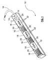
- FIG. 1is a perspective view of a power supply strip according to arrangements of the present invention.
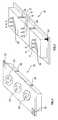
- FIG. 2is a top perspective view of a power module for the power supply strip of FIG. 1 .
- FIG. 3is a bottom perspective view of a power module for the power supply strip of FIG. 1 .
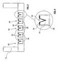
- FIG. 4is an end sectional view of an empty section of the power supply strip of FIG. 1 .
- FIG. 5is an expanded close up view of one of the power supply rails shown in FIG. 4 .
- FIG. 6is an end sectional view of a section of the power supply strip of FIG. 1 , with a power module inserted therein.
- FIG. 7is a side sectional view of a section of the power supply strip of FIG. 1 , with a power module inserted therein.
- exemplary embodiments of the present disclosureare described with respect to a power supply strip for electronic equipment. It should be understood by one of ordinary skill in the art that the exemplary embodiments of the present disclosure can be applied to other types of power supply arrangements.
- the strip 10comprises a housing 12 connected to an electrical supply cable 14 .
- the housing 12may be formed with a steel construction, or may be formed of any suitable material.
- the housingis preferably UL listed and sized to be rack mounted within a server cabinet, although any suitable size and shape may be employed. In certain arrangements, the housing 12 may be 4-5 feet long.
- the electrical supply cable 14may be any suitable cable. In one arrangement, the cable may be a 5-wire 200% ground, 200% neutral #10 conductor flexible copper whip capable of carrying a three-phase power supply, and may for example be 3 ⁇ 4 in width.
- Various amperage monitors 11typically one each for A, B, C phases, Neutral and Ground
- an RJ-45 jack 13typically one each for A, B, C phases, Neutral and Ground
- an optional 3-pole breaker 15may be provided.
- the housing 12may be arranged to comprise a plurality of power module ports 16 .
- Each power module port 16is sized to receive one power module 18 , which are illustrated in FIGS. 1-3 .
- Each power module 18can be sized to fit within a power module port 16 only one way, and may be screwed into place using screws 20 or any other suitable connection mechanism.
- Each power module 18may have three three-prong receptacles 22 , although of course any suitable socket or receptacle arrangement may be used. In one arrangement, the receptacles 22 can be L5-20 receptacles.
- Available receptacles for each power module 18may include L5-20R, L5-15R, 5-20R, L6-20R, L6-30R and 5-15R, which may be selectable by the user depending on the particular application. It will be appreciated that any type of receptacle arrangement can be provided for the power strip 10 , and that the selection of the particular power receptacle type that is used within each power module 18 may be made by the user to provide differing amp and voltage ratings to different pieces of electronic equipment, depending on the power requirements of that piece of equipment. For example, an L5-15R receptacle can provide 15 Amps, while an L6-30R receptacle can provide 30 Amps.
- All three receptacles 22 on one power module 18may be the same type of receptacle, or they may be different receptacles.
- the power modules 18may be supplied pre-wired with selected power receptacle types, and the user may simply select different power modules 18 that are appropriate for their requirements. Alternatively, the user may select the individual receptacles 22 . If the user does not need as many power modules 18 as there are power module ports 16 , one or more blank expansion modules (not shown) may be used to cover the power module port 16 .
- the blank expansion modulesmay simply be plates or may be the same general shape and size as the power modules 18 .
- connection pins or male conductors 24may be provided for each receptacle 22 .
- each of the three receptacles 22 on one power modulewill have a connection pin 26 for a different phase, as well as a connection for neutral and ground.
- one of the receptaclescan have connections for A-phase power, Neutral and Ground
- the second receptaclecan have connections for B-phase power, Neutral and Ground
- the third receptaclecan have connections for C-phase power, Neutral and Ground.
- Guide rails 28may be provided to help place the power module 18 within the power module port 16 of the housing 12 .
- Each conductor rail 30is connected to one of the A, B, C, N or G phases of the power supply cable 14 .
- Each conductor rail 30comprises a conductor 32 , such as copper, arranged on the surface of a generally V-shaped valley in a resilient conductive material 34 .
- the rail 30is surrounded (apart from the surface covered by the conductor 32 ) by an insulator 36 . It will be appreciated that the conductor 32 , resilient material 34 and insulator 36 may each be formed of any suitable material.
- wire conductors 38can be soldered 40 or otherwise connected between the connection pins 24 and connection pins 42 that are inserted into the rails 30 .
- the resilient material 34 in the rails 30holds the connection pins 42 under tension in a pressure fit arrangement.
- the relevant A, B, C, N or G phase pin receptacle of each receptacle 22 of the power module 18may be connected to the relevant power supply line.
- the connection pins 24 on the power module 18can be arranged to fit directly in the rails 30 , in a pressure fit arrangement. In this arrangement, each connection pin 24 is placed at an appropriate location to align with a chosen rail 30 when the power module 18 is pushed into the housing 12 . This removes the need to use wire conductors 38 .
- the power strip 10 of the present inventionenables a user to match the power receptacle 22 or receptacle to the power supply needs of the individual piece of electronic equipment being supplied. This means that the user can manage the power supply within a cabinet, without the need to supply multiple power circuits to a single cabinet.
Landscapes
- Engineering & Computer Science (AREA)
- General Engineering & Computer Science (AREA)
- Computer Hardware Design (AREA)
- Theoretical Computer Science (AREA)
- Architecture (AREA)
- Civil Engineering (AREA)
- Structural Engineering (AREA)
- Physics & Mathematics (AREA)
- General Physics & Mathematics (AREA)
- Microelectronics & Electronic Packaging (AREA)
- Details Of Connecting Devices For Male And Female Coupling (AREA)
- Connector Housings Or Holding Contact Members (AREA)
Abstract
Description
Claims (19)
Priority Applications (2)
| Application Number | Priority Date | Filing Date | Title |
|---|---|---|---|
| US12/365,675US8039997B2 (en) | 2009-02-04 | 2009-02-04 | Power supply strip for electronic equipment |
| PCT/US2010/023044WO2010091079A1 (en) | 2009-02-04 | 2010-02-03 | Power supply strip for electronic equipment |
Applications Claiming Priority (1)
| Application Number | Priority Date | Filing Date | Title |
|---|---|---|---|
| US12/365,675US8039997B2 (en) | 2009-02-04 | 2009-02-04 | Power supply strip for electronic equipment |
Publications (2)
| Publication Number | Publication Date |
|---|---|
| US20100194194A1 US20100194194A1 (en) | 2010-08-05 |
| US8039997B2true US8039997B2 (en) | 2011-10-18 |
Family
ID=42397095
Family Applications (1)
| Application Number | Title | Priority Date | Filing Date |
|---|---|---|---|
| US12/365,675Expired - Fee RelatedUS8039997B2 (en) | 2009-02-04 | 2009-02-04 | Power supply strip for electronic equipment |
Country Status (2)
| Country | Link |
|---|---|
| US (1) | US8039997B2 (en) |
| WO (1) | WO2010091079A1 (en) |
Cited By (7)
| Publication number | Priority date | Publication date | Assignee | Title |
|---|---|---|---|---|
| US20100328849A1 (en)* | 2009-06-25 | 2010-12-30 | Ewing Carrel W | Power distribution apparatus with input and output power sensing and method of use |
| US20120002356A1 (en)* | 2010-04-07 | 2012-01-05 | The Wiremold Company | Customizable bus system |
| US9640960B2 (en) | 2010-04-07 | 2017-05-02 | The Wiremold Company | Customizable bus systems |
| US9952261B2 (en) | 2009-03-04 | 2018-04-24 | Server Technology, Inc. | Monitoring power-related parameters in a power distribution unit |
| US10154610B2 (en) | 2014-05-06 | 2018-12-11 | Vertiv Corporation | Apparatus for distributing power |
| WO2020020470A1 (en)* | 2018-07-27 | 2020-01-30 | Riedo Networks Ag | Power distribution unit with a modular construction |
| US10642299B2 (en) | 2007-12-28 | 2020-05-05 | Server Technology, Inc. | Power distribution, management, and monitoring systems and methods |
Families Citing this family (3)
| Publication number | Priority date | Publication date | Assignee | Title |
|---|---|---|---|---|
| US20130252473A1 (en)* | 2012-03-22 | 2013-09-26 | Hamilton Sundstrand Corporation | Gangable power supply channels |
| CN106099512B (en)* | 2016-06-29 | 2023-08-25 | 居言智能技术(江苏)有限公司 | Rail type power socket |
| US12424830B2 (en)* | 2022-04-12 | 2025-09-23 | Kenneth Horvath | Power distribution box with amperage readings |
Citations (11)
| Publication number | Priority date | Publication date | Assignee | Title |
|---|---|---|---|---|
| US3124403A (en)* | 1964-03-10 | Electrical bus conductor | ||
| US3835442A (en)* | 1973-02-01 | 1974-09-10 | Bunker Ramo | Termination module utilizing conductive elastomer bussing |
| US5126514A (en) | 1989-09-07 | 1992-06-30 | Delachaux S.A. | Process for producing an electrical supply rail |
| US20030033364A1 (en) | 2001-08-10 | 2003-02-13 | Garnett Paul J. | Interfacing computer modules |
| US6628009B1 (en)* | 2000-10-06 | 2003-09-30 | The Root Group, Inc. | Load balanced polyphase power distributing system |
| US20050211835A1 (en)* | 2004-03-27 | 2005-09-29 | Henley James T | Continuous power bus for seat power |
| US6972375B2 (en)* | 2002-10-21 | 2005-12-06 | Denso Corporation | Wiring harness |
| US20060044766A1 (en) | 2003-02-27 | 2006-03-02 | Marc Hartel | Frame comprising an electrifying device |
| US20060146581A1 (en) | 2004-12-27 | 2006-07-06 | Rack Distribution Products, Llc | Power distribution device |
| US20070281526A9 (en) | 2001-11-28 | 2007-12-06 | Donahue William F Iv | Modular power distribution unit, module for the power distribution unit, and method of using the same |
| US20090236909A1 (en) | 2008-03-19 | 2009-09-24 | Liebert Corporation | Adaptive Power Strip |
- 2009
- 2009-02-04USUS12/365,675patent/US8039997B2/ennot_activeExpired - Fee Related
- 2010
- 2010-02-03WOPCT/US2010/023044patent/WO2010091079A1/enactiveApplication Filing
Patent Citations (11)
| Publication number | Priority date | Publication date | Assignee | Title |
|---|---|---|---|---|
| US3124403A (en)* | 1964-03-10 | Electrical bus conductor | ||
| US3835442A (en)* | 1973-02-01 | 1974-09-10 | Bunker Ramo | Termination module utilizing conductive elastomer bussing |
| US5126514A (en) | 1989-09-07 | 1992-06-30 | Delachaux S.A. | Process for producing an electrical supply rail |
| US6628009B1 (en)* | 2000-10-06 | 2003-09-30 | The Root Group, Inc. | Load balanced polyphase power distributing system |
| US20030033364A1 (en) | 2001-08-10 | 2003-02-13 | Garnett Paul J. | Interfacing computer modules |
| US20070281526A9 (en) | 2001-11-28 | 2007-12-06 | Donahue William F Iv | Modular power distribution unit, module for the power distribution unit, and method of using the same |
| US6972375B2 (en)* | 2002-10-21 | 2005-12-06 | Denso Corporation | Wiring harness |
| US20060044766A1 (en) | 2003-02-27 | 2006-03-02 | Marc Hartel | Frame comprising an electrifying device |
| US20050211835A1 (en)* | 2004-03-27 | 2005-09-29 | Henley James T | Continuous power bus for seat power |
| US20060146581A1 (en) | 2004-12-27 | 2006-07-06 | Rack Distribution Products, Llc | Power distribution device |
| US20090236909A1 (en) | 2008-03-19 | 2009-09-24 | Liebert Corporation | Adaptive Power Strip |
Cited By (11)
| Publication number | Priority date | Publication date | Assignee | Title |
|---|---|---|---|---|
| US10642299B2 (en) | 2007-12-28 | 2020-05-05 | Server Technology, Inc. | Power distribution, management, and monitoring systems and methods |
| US9952261B2 (en) | 2009-03-04 | 2018-04-24 | Server Technology, Inc. | Monitoring power-related parameters in a power distribution unit |
| US20100328849A1 (en)* | 2009-06-25 | 2010-12-30 | Ewing Carrel W | Power distribution apparatus with input and output power sensing and method of use |
| US8305737B2 (en)* | 2009-06-25 | 2012-11-06 | Server Technology, Inc. | Power distribution apparatus with input and output power sensing and method of use |
| US9898026B2 (en) | 2009-06-25 | 2018-02-20 | Server Technology, Inc. | Power distribution apparatus with input and output power sensing and method of use |
| US20120002356A1 (en)* | 2010-04-07 | 2012-01-05 | The Wiremold Company | Customizable bus system |
| US8625255B2 (en)* | 2010-04-07 | 2014-01-07 | The Wiremold Company | Customizable bus system |
| US9640960B2 (en) | 2010-04-07 | 2017-05-02 | The Wiremold Company | Customizable bus systems |
| US10154610B2 (en) | 2014-05-06 | 2018-12-11 | Vertiv Corporation | Apparatus for distributing power |
| WO2020020470A1 (en)* | 2018-07-27 | 2020-01-30 | Riedo Networks Ag | Power distribution unit with a modular construction |
| US12114458B2 (en) | 2018-07-27 | 2024-10-08 | Riedo Networks Ag | Power distribution unit with a modular construction |
Also Published As
| Publication number | Publication date |
|---|---|
| WO2010091079A1 (en) | 2010-08-12 |
| US20100194194A1 (en) | 2010-08-05 |
Similar Documents
| Publication | Publication Date | Title |
|---|---|---|
| US8039997B2 (en) | Power supply strip for electronic equipment | |
| US11411358B2 (en) | Outlet connection schema for a PDU | |
| US11133626B2 (en) | High outlet density power distribution unit | |
| AU2018236783B2 (en) | Method and apparatus for multiple input power distribution to adjacent outputs | |
| RU2569552C2 (en) | Device and method of electric power distribution with potential scaling | |
| EP2659754B1 (en) | Configurable rack and related methods | |
| US8503149B2 (en) | Apparatus and method for scalable power distribution | |
| US7619868B2 (en) | Apparatus and method for scalable power distribution | |
| US11296467B2 (en) | High outlet density power distribution unit | |
| US7830043B1 (en) | Adaptable computer rack for power distribution | |
| US8289729B2 (en) | PCB interconnect scheme for PSU | |
| EP3284147B1 (en) | Outlet connector for a high outlet density power distribution unit | |
| US20110212634A1 (en) | Ac interconnect scheme for psu | |
| JP5725952B2 (en) | Circuit breaker and adapter for circuit breaker | |
| JP2000035838A (en) | Bus for power distribution and its manufacture | |
| CN223007117U (en) | Server power supply | |
| US8791605B2 (en) | DC interconnect scheme for PSU | |
| WO2022055793A1 (en) | Modular and scalable power distribution system |
Legal Events
| Date | Code | Title | Description |
|---|---|---|---|
| AS | Assignment | Owner name:THERMOCABINET, LLC, ARIZONA Free format text:ASSIGNMENT OF ASSIGNORS INTEREST;ASSIGNOR:SLESSMAN, GEORGE;REEL/FRAME:022237/0429 Effective date:20090204 | |
| AS | Assignment | Owner name:WELLS FARGO BANK, NATIONAL ASSOCIATION, NORTH CARO Free format text:SECURITY AGREEMENT;ASSIGNORS:IO DATA CENTERS, LLC;THERMOCABINET, LLC;REEL/FRAME:025108/0372 Effective date:20101006 | |
| ZAAA | Notice of allowance and fees due | Free format text:ORIGINAL CODE: NOA | |
| ZAAB | Notice of allowance mailed | Free format text:ORIGINAL CODE: MN/=. | |
| AS | Assignment | Owner name:IO DATA CENTERS, LLC, ARIZONA Free format text:ASSIGNMENT OF ASSIGNORS INTEREST;ASSIGNOR:THERMOCABINET, LLC;REEL/FRAME:026960/0561 Effective date:20110921 | |
| STCF | Information on status: patent grant | Free format text:PATENTED CASE | |
| AS | Assignment | Owner name:WELLS FARGO BANK, NATIONAL ASSOCIATION, AS ADMINIS Free format text:PATENT SECURITY AGREEMENT;ASSIGNOR:IO DATA CENTERS, LLC;REEL/FRAME:030194/0693 Effective date:20130410 | |
| AS | Assignment | Owner name:IO DATA CENTERS, LLC, ARIZONA Free format text:RELEASE OF PATENT SECURITY INTEREST RECORDED AT REEL 030194, FRAME 0693;ASSIGNOR:WELLS FARGO BANK, NATIONAL ASSOCIATION, AS ADMINISTRATIVE AGENT;REEL/FRAME:035121/0931 Effective date:20150227 | |
| AS | Assignment | Owner name:IO DATA CENTERS, LLC, ARIZONA Free format text:RELEASE OF PATENT SECURITY INTEREST RECORDED AT REEL 25108, FRAME 372;ASSIGNOR:WELLS FARGO BANK, NATIONAL ASSOCIATION, AS ADMINISTRATIVE AGENT;REEL/FRAME:035122/0874 Effective date:20150227 | |
| AS | Assignment | Owner name:BASELAYER TECHNOLOGY, LLC, ARIZONA Free format text:ASSIGNMENT OF ASSIGNORS INTEREST;ASSIGNOR:IO DATA CENTERS, LLC;REEL/FRAME:035314/0402 Effective date:20150227 | |
| REMI | Maintenance fee reminder mailed | ||
| FPAY | Fee payment | Year of fee payment:4 | |
| SULP | Surcharge for late payment | ||
| MAFP | Maintenance fee payment | Free format text:PAYMENT OF MAINTENANCE FEE, 8TH YR, SMALL ENTITY (ORIGINAL EVENT CODE: M2552); ENTITY STATUS OF PATENT OWNER: SMALL ENTITY Year of fee payment:8 | |
| FEPP | Fee payment procedure | Free format text:MAINTENANCE FEE REMINDER MAILED (ORIGINAL EVENT CODE: REM.); ENTITY STATUS OF PATENT OWNER: SMALL ENTITY | |
| LAPS | Lapse for failure to pay maintenance fees | Free format text:PATENT EXPIRED FOR FAILURE TO PAY MAINTENANCE FEES (ORIGINAL EVENT CODE: EXP.); ENTITY STATUS OF PATENT OWNER: SMALL ENTITY | |
| STCH | Information on status: patent discontinuation | Free format text:PATENT EXPIRED DUE TO NONPAYMENT OF MAINTENANCE FEES UNDER 37 CFR 1.362 | |
| FP | Lapsed due to failure to pay maintenance fee | Effective date:20231018 |